1
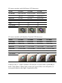
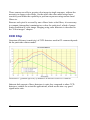
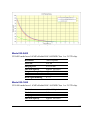
G2 CCD
Operating
Manual
Version 2.3
Modified on November 26th, 2009
All information furnished by Moravian Instruments is believed to be accurate.
Moravian Instruments reserves the right to change any information contained
herein without notice.
G2 CCD devices are not authorized for and should not be used within Life
Support Systems without the specific written consent of the Moravian
Instruments. Product warranty is limited to repair or replacement of defective
components and does not cover injury or property or other consequential
damages.
Copyright © 2000-2009, Moravian Instruments
Moravian Instruments
Masarykova 1148
763 02 Zlín
Czech Republic
tel./fax: +420 577 107 171
www:
http://www.gxccd.com/
e-mail: [email protected]
Table of Contents
Introduction....................................................................................................5
Camera Technical Specifications...................................................................7
CCD Chip...............................................................................................10
Model G2-0402.................................................................................11
Model G2-1600.................................................................................11
Model G2-3200.................................................................................12
Model G2-2000.................................................................................12
Model G2-4000.................................................................................12
Camera Electronics.................................................................................13
Model G2-0402.................................................................................14
Model G2-1600.................................................................................14
Model G2-3200.................................................................................14
Model G2-2000.................................................................................14
Model G2-4000.................................................................................15
CCD Chip Cooling.................................................................................15
Power Supply..........................................................................................16
Mechanical Specifications......................................................................17
Package Contents....................................................................................18
Optional components..............................................................................19
Filter Wheel for five 1.25 inch threaded filter cells..........................19
Filter Wheel for six 1-inch glass-only filters....................................20
LRGB filter set..................................................................................20
Clear (C) filter...................................................................................21
UBVRI filter set................................................................................21
Separate filters...................................................................................21
Telescope adapter..............................................................................22
Getting Started..............................................................................................24
Camera System Driver Installation.........................................................24
Windows XP System Driver Installation..........................................24
Windows 2000 System Driver Installation.......................................25
SIMS Software Installation.....................................................................26
SIMS configuration files...................................................................26
G2 CCD Camera Driver for SIMS.........................................................27
Camera Connection................................................................................29
Camera LED state indicator..............................................................30
Working with Multiple Cameras............................................................30
Camera Operation.........................................................................................32
Camera and the Telescope......................................................................33
Temperature Control...............................................................................33
First Images............................................................................................36
Brightness and Contrast – Image Stretching..........................................37
Calibration..............................................................................................38
Color Images with monochrome camera and filters...............................40
Color images with color camera.............................................................42
Balancing colors.....................................................................................45
Some General Rules for Successful Imaging...............................................46
Camera Maintenance....................................................................................49
Desiccant exchange................................................................................49
Changing the silica-gel in G2 cameras revision 3.............................50
Changing the silica-gel in G2 cameras revision 1 and 2...................51
Changing Filters......................................................................................52
Opening the camera head of G2 cameras revision 3.........................52
Opening the camera head of G2 cameras revision 1 and 2...............52
Changing the Whole Filter Wheel..........................................................55
Changing the Telescope Adapter............................................................55
Power Supply Fuse.................................................................................55
Introduction
Thank you for choosing the G2 CCD camera. The cooled, slow-scan series of
G2 CCD cameras were developed for imaging under extremely low-light
conditions in astronomy, microscopy and similar areas. The development team
focused to every detail of camera mechanics, cooling, electronics and software
to create state-of-the-art product. G2 CCD cameras feature compact and robust
construction, rich features, sophisticated software support and easy operation.
Please note the G2 CCD cameras are designed to work in cooperation with a
host Personal Computer (PC). As opposite to digital still cameras, which are
operated independently on the computer, the scientific slow-scan, cooled
cameras usually require computer for operation control, image download,
processing and storage etc. To operate G2 CCD camera, you need a computer
which:
1.
Is compatible with a PC standard.
2.
Runs a modern 32-bit Windows operating system.
G2 camera USB driver is designed for Windows 2000 and better
operating systems (e.g. Windows XP). Old 16/32-bit systems, like
Windows 95/98 and Windows Me, are not supported. G2 CCD
cameras cannot properly operate with such operating systems.
3.
Provides at last one free USB port.
The current series of G2 CCD cameras are designed to operate with
USB 2.0 high-speed (480 Mbps) hosts. Although they are fully
backward compatible with USB 1.1 full-speed (12 Mbps) hosts, image
download time can be somewhat longer if USB 1.1 connection is used.
A simple and cheap device called USB hub can expand number of
available USB port. Typical USB hub occupies one computer USB
port and offers four free ports. Make sure the USB hub is USB 2.0
high-speed compatible.
But keep on mind that if more USB devices connected to one hub need
to communicate with a host PC, USB hub shares its single up link line
5
to the host PC. Although G2 CCD cameras can operate through a USB
hub, it can negatively affect the camera performance, like download
time etc. It is recommended to connect other USB devices through
USB hub (e.g. the mouse) and to provide the camera a direct USB
connection to the host PC.
The G2 CCD camera needs an external power supply to operate. It is not
possible to run the camera from the power lines provided by the USB cable,
which is common for webcams or very simple imagers. G2 CCD cameras
integrate highly efficient CCD chip cooling, shutter and filter wheel, so their
power requirements significantly exceed USB line power capabilities. On the
other side separate power source eliminates problems with voltage drop on long
USB cables or with drawing of laptop batteries etc.
Also note the camera must be connected to some optical system (e.g. the
telescope) to capture images. The camera is designed for long exposures,
necessary to acquire the light from faint objects. If you plan to use the camera
with the telescope, make sure the whole telescope/mount setup is capable to
track the target object smoothly during the exposure.
6
Camera Technical Specifications
G2 series of CCD cameras are manufactured with two kinds of CCD detectors:
●
G2 cameras with Kodak KAF (Full Frame – FF) CCD architecture.
Almost all Full Frame CCD detector area is exposed to light. This is
why these detectors provide very high quantum efficiency. Although
Full Frame detectors could be equipped with so-called Anti Blooming
Gate (ABG), which prohibits blooming of the charge to neighboring
pixels when image is over-exposed, G2 cameras do not use ABG
version of CCD detectors. This ensures maximal possible linear
response to light in the whole dynamic range.
Cameras with Full Frame, non-ABG detectors are suitable for
scientific applications, where linear response is necessary for
photometric applications in astronomy, microscopy etc. High quantum
efficiency could be used also for narrow-band imaging, where
overexposure is a rare exception, and for imaging of small objects
without a bright star in the field of view.
Illustration 1: “Full Frame” CCD schematic diagram
7
●
G2 cameras with Kodak KAI (Interline Transfer – IT) architecture.
There is a shielded column of pixels just beside each column of active
pixels on these detectors. The shielded columns are called Vertical
registers. One pulse moves charge from exposed pixels to shielded
pixels on the end of each exposure. The the charge is moved from
vertical registers to horizontal register and digitized in the same way
like in the case of Full Frame detectors. This mechanism is also known
as “electronic shuttering”, because it allows very short exposures and
also digitization of the image without mechanically shielding of the
detector from incoming light.
Also G2 cameras with IT CCDs are equipped with mechanical shutter,
because electronic shutter does not allow dark-frame exposures,
necessary for proper image calibration etc.
The price for electronic shutter if lower quantum efficiency
(sensitivity) of IT detectors compared to FF ones. Also all IT detectors
are equipped with ABG, so they can acquire images of very bright
objects without charge blooming to neighboring pixels.
Illustration 2: “Interline Transfer” CCD schematic diagram
8
G2 camera models with Full Frame CCD detectors:
Model
G2-0402
G2-1600
G2-3200
CCD chip
KAF-0402ME
KAF-1603ME
KAF-3200ME
Resolution
768×512
1536×1024
2184×1472
Pixel size
9×9 µm
9×9 µm
6.8×6.8 µm
CCD area
6.9×4.6 mm
13.8×9.2 mm
14.9×10.0 mm
ABG
No
No
No
Color mask
No
No
No
G2 camera models with Interline Transfer CCD detectors::
Model
G2-2000
G2-2000C
G2-4000
G2-4000C
CCD chip
KAI-2020
KAI-2020
KAI-4022
KAI-4022
Resolution
1604×1204
1604×1204
2056×2062
2056×2062
Pixel size
7.4×7.4 µm
7.4×7.4 µm
7.4×7.4 µm
7.4×7.4 µm
CCD area
11.8×9.0 mm
11.8×9.0 mm
15.2×15.2 mm
15.2×15.2 mm
ABG
Yes
Yes
Yes
Yes
Color mask
No
Yes
No
Yes
Cameras with “C” suffix contains CCD detector covered with so-called Bayer
mask. Color filters of three basic colors (red, green, blue) cover all pixels, so
every pixels detects only light of particular color.
9
These cameras are able to acquire color image in single exposure, without the
necessity to change color filters. On the other side color mask brings lower
sensitivity and limits the capability to perform exposures using narrow-band
filters etc.
Because each pixel is covered by one of three basic color filters, it is necessary
to compute (interpolate) remaining two colors for each pixel, which of course
limits resolution of color image. Imaging using color detectors is described in
the “Color images” chapter.
CCD Chip
Quantum efficiency (sensitivity) of CCD detectors used in G2 cameras depends
on the particular camera model.
Illustration 3: Quantum efficiency of Kodak CCD detectors used in G2 cameras
Inherent dark current of these detectors is quite low compared to other CCD
detectors, suitable for scientific applications, which results into very good
signal/noise ratio.
10
Illustration 4: Temný proud CCD čipů Kodak používaných v kamerách série G2
Model G2-0402
G2-0402 model uses 0.4 MPx Kodak KAF-0402ME Class 1 or 2 CCD chip.
Resolution
768×512 pixels
Pixel size
9×9 µm
Imaging area
6.9×4.6 mm
Full well capacity
Approx. 100 000 e-
Output node capacity
Approx. 220 000 e-
Dark current
1 e-/s/pixel at 0°C
Dark signal doubling
6.3 °C
Model G2-1600
G2-1600 model uses 1.6 MPx Kodak KAF-1603ME Class 1 or 2 CCD chip.
Resolution
1536×1024 pixels
Pixel size
9×9 µm
Imaging area
13.8×9.2 mm
Full well capacity
Approx. 100 000 e-
11
Output node capacity
Approx. 220 000 e-
Dark current
1 e-/s/pixel at 0°C
Dark signal doubling
6.3 °C
Model G2-3200
G2-3200 model uses 3.2 MPx Kodak KAF-3200ME Class 1 or 2 CCD chip.
Resolution
2184×1472 pixels
Pixel size
6.8×6.8 µm
Imaging area
14.9×10.0 mm
Full well capacity
Approx. 55 000 e-
Output node capacity
Approx. 110 000 e-
Dark current
0.8 e-/s/pixel at 0°C
Dark signal doubling
6 °C
Model G2-2000
G2-2000 uses 2 MPx CCD Kodak KAI-2020.
Resolution
1604×1204 pixels
Pixel size
7.4×7.4 µm
Imaging area
11.9×8.9 mm
Full well capacity
Approx. 40 000 e-
Output node capacity
Approx. 100 000 e-
Dark current
0.3 e-/s/pixel at 0°C
Dark signal doubling
7 °C
KAI-2020 CCD detector with color (Bayer) mask can be used in the G2-2000
camera.
Model G2-4000
G2-2000 uses 4 MPx CCD Kodak KAI-4022.
12
Resolution
2056×2062 pixels
Pixel size
7.4×7.4 µm
Imaging area
15.2×15.2 mm
Full well capacity
Approx. 40 000 e-
Output node capacity
Approx. 100 000 e-
Dark current
0.3 e-/s/pixel at 0°C
Dark signal doubling
7 °C
KAI-4022 CCD detector with color (Bayer) mask can be used in the G2-4000
camera.
Camera Electronics
16-bit A/D converter with correlated double sampling ensures high dynamic
range and CCD chip-limited readout noise. Fast USB interface ensures image
download time within seconds. Maximum length of single USB cable is 5 m.
This length can be extended to 10 m by using single USB hub or active USB
extender cable. Up to 5 hubs or active extenders can be used in one connection.
Third party USB extenders provide up to 100 m extension.
ADC resolution
16 bits
Sampling method
Correlated double sampling
Read modes
Standard
Low-noise
Horizontal binning
1 to 4 pixels
Vertical binning
1 to 4 pixels
Sub-frame readout
Arbitrary sub-frame
TDI readout
Only on KAF based cameras
Computer interface
USB 2.0 high-speed
USB 1.1 full-speed compatible
Binning can be combined independently on both axes.
Image download time and system read noise depends on the CCD chip used in
particular camera model.
13
Model G2-0402
Gain
1.5e-/ADU (1×l binning)
2.3e-/ADU (other binnings)
System read noise
12 e- (LN read)
15 e- (Standard read)
Full frame download
0.6 s (LN read)
0.5 s (Standard read)
Model G2-1600
Gain
1.5e-/ADU (1×l binning)
2.3e-/ADU (other binnings)
System read noise
12 e- (LN read)
15 e- (Standard read)
Full frame download
2.5 s (LN read)
2.1 s (Standard read)
Model G2-3200
Gain
1.0 e-/ADU (1×l binning)
1.4e-/ADU (other binnings)
System read noise
7 e- (LN read)
10 e- (Standard read)
Full frame download
5.6 s (LN read)
4.8 s (Standard read)
Model G2-2000
Gain
1,0 e-/ADU (all binnings)
System read noise
8 e- (LN read)
10 e- ( Standard read)
Full frame download
3.1 s (LN read)
2.6 s ( Standard read)
14
Model G2-4000
Gain
1.0 e-/ADU (all binnings)
System read noise
7 e- (LN read)
10 e- (Standard read)
Full frame download
6.8 s (LN read)
5.7 s (Standard read)
System read noise depends on the particular CCD detector. For instance KAF0402 or KAF-1603 CCDs can be read with 11 11 e- RMS, read noise of the
KAF-3200 CCD can be less than 6 e- RMS.
Download times are valid for cameras of revision 3 and newer. Download times
for cameras of revision 2 was approx. 2 times longer and for cameras of
revision 1 almost 2.5 times longer.
Download times are valid for USB 2.0 host and may vary depending on host
PC. Times stated here were measured on 1.5 GHz Pentium M based laptop
computer.
CCD Chip Cooling
Regulated two-stage thermo-electric cooling is capable to cool the CCD chip up
to 50 °C below ambient temperature. The Peltier hot side is cooled by a fan.
The CCD chip temperature is regulated with ±0.1 °C precision. High
temperature drop and precision regulation ensure very low dark current for long
exposures and allow image proper calibration.
The camera head contains two temperature sensors – the first sensor measures
directly the temperature of the CCD chip. The second one measures the
temperature of the air cooling the Peltier hot side.
The cooling performance depends on the environmental conditions and also on
the power supply. If the power supply voltage drops below 12 V, the maximum
temperature drop is lower.
CCD chip cooling
Thermoelectric (Peltier modules)
15
TEC modules
Two stages
Maximal ∆T
>50 °C below ambient
Regulated ∆T
48 °C below ambient (85% cooling)
Regulation precision ±0.1 °C
Hot side cooling
Forced air cooling (fan)
Optional heat exchanger for liquid coolant
Maximum temperature difference between CCD and ambient air may exceed
50 °C when the cooling runs at 100% power. However, temperature cannot be
regulated in such case, camera has no room for lowering the CCD temperature
when the ambient temperature rises. The 45 °C temperature drop can be
achieved with cooling running at approx. 85% power, which provides enough
room for regulation.
Power Supply
The 12 V DC power supply enables camera operation from arbitrary power
source including batteries, wall adapters etc. Universal 100-240 V AC/5060 Hz, 60 W “brick” adapter is supplied with the camera. Although the camera
power consumption does not exceed 30 W, the 60 W power supply ensures
noise-free operation.
Camera head supply
12 V DC
Camera head power consumption 30 W
16
Adapter input voltage
100-240 V AC/50-60 Hz
Adapter output voltage
12 V DC/5 A
Adapter maximum power
60 W
1.
Maximum power consumption includes 100% cooling.
2.
The camera contains its own power supplies inside, so it can be
powered by unregulated 12 V DC power source – the input voltage
can be anywhere between 10 and 14 V. However, some parameters
(like cooling efficiency) can degrade if the supply drops below 12 V.
3.
G2 CCD camera measures its input voltage and provides it to the
control software. Input voltage is displayed in the Cooling tab of the
CCD Camera control tool in the SIMS. This feature is important
especially if you power the camera from batteries.
Warning:
The power connector on the camera head uses center-plus pin. Although all
modern power supplies use this configuration, always make sure the polarity is
correct if you use own power source.
Mechanical Specifications
Compact and robust camera head measures only 114×114×74 mm
(4.5×4.5×3 inches). The head is CNC-machined from high-quality aluminum
and black anodized. The head itself contains USB-B (device) connector and
12 V DC power plug, no other parts (CPU box, USB interface, etc.), except a
“brick” power supply, are necessary. Integrated mechanical shutter allows
streak-free image readout, as well as automatic dark frame exposures, which
are necessary for unattended, robotic setups. Integrated filter wheel contains 5
positions for standard 1.25-inch threaded filter cells. A variant of filter wheel
with 6 positions for the same filters without cells (only a glass) is also
available.
Internal mechanical shutter
Yes, blade shutter
Shortest exposure time
0.09 s (cameras with KAF CCDs)
0,05 s (cameras with KAI CCDs)
Longest exposure time
Limited by chip saturation only
Internal filter wheel
5-positions for 1.25" threaded filter cells
6-positions for 1" bolt-secured filters
Head dimensions
114×114×77 mm
Back focal distance
29 mm
Camera head weight
1.1 kg
Shortest exposure time is valid for G2 cameras revision 3 and higher. Cameras
revision 1 and 2 have shortest exposure time two times longer.
17
Package Contents
G2 CCD cameras are supplied in the foam-filled, hard carrying case containing:
●
Camera body with a user-chosen telescope adapter. The standard 2"
barrel adapter is included by default. If ordered, the filter wheel is
already mounted inside the camera head and filters are threaded into
place (if ordered).
●
A 100-240 V AC/50-60 Hz input, 12 V DC/5 A output power supply
adapter with 1.5 m long output cable. The adapter includes AC cable.
Illustration 5: 12 V DC/5 A power supply adapter for
G2 CCD Camera
●
5 m long USB A-B cable for connecting camera to host PC.
Warning:
5 m (approx. 15 feet) is the maximum allowed length of USB cable.
Do not try to connect 5 m USB A-B cable with USB A-A extension
cable to get a longer connection. When the distance between camera
and host PC is longer, USB hub or an active USB extender cable can
be used as a repeater to provide up to 10 m long connection. Thirdparty USB extenders allow USB connection tens or even hundreds
meters long.
18
●
A CD-ROM with camera drivers, SIMS software package with
electronic documentation and PDF version of this manual.
●
A printed copy of this manual.
Optional components
Number of optional parts are available for G2 CCD cameras. These parts can
be ordered separately. Refer to our web site for the pricing, please.
Filter Wheel for five 1.25 inch threaded filter cells
Because the filter wheel is not necessary for some applications (e.g. in
microscopy), a version of G2 camera without filter wheel is also offered. Make
sure you choose the variant with filter wheel included, even if you plan to use
own filters and you order camera without LRGB filters.
The filter wheel can be added later, but this operation is more complex
compared to simply replacing the existing filter wheel. Camera intended for use
without filter does not contain filter wheel drive and position detection
electronics. Such camera must be returned to the manufacturer to install filter
drive.
Illustration 6: Filter wheel for G2 CCD camera with
LRGB filters installed
19
Another filter wheel can be also ordered separately. Replacing the whole filter
wheel is easier than replacing individual filters. It is possible to thread for
instance LRGB filter set into one wheel, BVRI set into second wheel and
narrow-band filters (Hα, OIII, ...) into the third one.
Filter Wheel for six 1-inch glass-only filters
Another option is using of 1-inch, glass-only filters in 6-positions filter wheel.
1-inch filter is big enough to cover all sizes of CCD chips used in G2 CCD
cameras. This filter wheel allows for instance using of complete UBVRI filter
set and leave one position for Clear filter or empty.
Illustration 7: Five-positions filter wheel (left) and six-positions
filter wheel (right)
Each filters is fixed in the wheel by three plastic M3 screws.
Warning:
Filter wheels with different number of filter positions cannot be used
interchangeably in one camera without changes in camera firmware. Camera
must be sent to the manufacturer if the user decides to use filter wheel with
different number of positions.
LRGB filter set
High quality 1.25" LRGB filter set optimized for CCD imaging. This set
20
contains high-pass Red, Green and Blue filters plus Luminance filter covering
the combined RGB spectral range, blocking IR and UV portion of spectrum for
maximum color accuracy.
Clear (C) filter
Optional clear filter (optical glass with AR coatings) of the same thickness like
RGB filters can be used in addition to (or instead of) Luminance filter to use
maximum chip QE for luminance images. Optical glass is used instead of
simple empty hole in filter wheel to ensure proper focus and to eliminate
refocusing when changing from filtered to unfiltered exposures.
The Clear filer can be also combined with RGB so it is possible to install
CRGB filter set and to leave one empty filter wheel position.
UBVRI filter set
Scientific-grade Schott glass UBVRI filter set in 1.25" cells. This set contains
scientific Blue, Visual, Red and Infra-red filters for photometric applications.
Illustration 8: BVRI filters in 1.25 inch cells
Separate filters
Number of 1.25" filters for narrow-band imaging and other special applications
(UHC, Hα, Hβ, OIII, SII, etc.) are available. Visit our web site for current filter
offering.
21
Telescope adapter
The camera is supplied with standard 2" barrel adapter by default, but the user
can choose any other adapter he/she prefers. Another adapters can be ordered
separately.
It is possible to choose among various telescope/lens adapters:
22
1.25" barrel
adapter
Adapter for 1.25" focusers.
2" barrel adapter
Adapter for 2" focusers.
T-thread short
M42×0.75 mm inner thread,
8 mm long.
T-thread long
M42×0.75 mm inner thread,
preserves 55 mm back focal
distance as defined by
Tamron.
Prakcica lens
adapter
M42×1 mm inner thread,
preserves 46 mm back focal
distance.
Zeiss adapter
M44×1 mm outer thread,
includes fixing nut.
Canon EOS lens
adapter
Standard Canon bayonet
adapter
Nikon F lens
adapter
Standard Nikon F bayonet
adapter
PSB-1100 adapter
Threaded adapter for
TeleVue PSB-1100 coma
corrector
Adapters are attached to the camera body using four M3 (3 mm metric) screws,
placed on the corners of 44 mm square. Custom adapters can be made upon
request.
23
Getting Started
Although the camera is intended for operation at night (or for very low-light
conditions at day), it is always better (and highly recommended) to install
software and to make sure everything is working OK during day, before the
first night under the stars.
The G2 CCD cameras can be in principle operated under various CCD control
software packages (refer to our web site for available drivers), this manual
demonstrates camera operation under the SIMS (Simple Image Manipulation
system) – camera control and image processing software suite supplied with the
camera.
Camera System Driver Installation
Every USB device requires so-called “system driver”, incorporated directly into
the operating system kernel. Some devices (for instance USB Flash Disk
dongles) conform to some predefined class (USB mass-storage device class in
this case), so they can use the driver already present in the operating system.
But this is not the case of the G2 CCD camera – it requires its own system
driver to be installed.
The simplest way to install G2 CCD camera system driver is to utilize Plugand-play nature of USB devices and Windows operating system. Simply plug
the camera to power supply and connect it to the host PC using the included
USB A-B cable. Windows detects new USB device and opens hardware
installation wizard. The system driver installation is slightly different on
Windows XP and Windows 2000.
Windows XP System Driver Installation
The operating system notifies the new USB device was plugged in the “Found
new hardware bubble”. The system then opens the “Found New Hardware”
Wizard.
1.
24
The wizard offers searching for suitable driver on Windows Update
site. Reject this offer (choose “No, not this time”) and click “Next”
button.
2.
Choose the “Install the software automatically” in the next step.
Insert the CD-ROM into the drive and the wizard will continue by the
next step.
It is not necessary to install files from CD-ROM. It is possible to copy
the folder containing driver files e.g. to shared network volume, USB
Flash Disk etc. Then it is necessary to choose the “Install from a list or
specific location” and to define the path to driver files.
3.
The wizard starts to copy files. But Windows XP checks for driver file
digital signature. If it cannot find the signature, it notifies the user by a
message box. Click “Continue Anyway”, the digital signature is only
an administrative step and does not influence the proper functionality.
4.
The wizard then finishes the installation and the G2 CCD camera is
ready to work.
Windows 2000 System Driver Installation
The operating system notifies the new USB device was plugged in the “Found
new hardware” message box. The system then opens the “Found New
Hardware Wizard”. Click the “Next” button to start the installation.
1.
Choose the “Search for a suitable driver for my device” and click
“Next” button.
2.
Drivers are supplied on the CD-ROM, choose “CD-ROM drives” and
continue by clicking “Next” button.
It is not necessary to install files from CD-ROM. It is possible to copy
the folder containing driver files e.g. to shared network volume, USB
Flash Disk etc. Then it is necessary to choose “Specify a location” and
define the path to driver files.
3.
The Wizard notifies it found proper driver and installs it. The
installation is finished and the G2 CCD camera is ready to work.
Please note the Windows system keeps the information about installed devices
separately for each USB port. If you later connect G2 CCD camera to different
25
USB port (different USB connector on the PC or through the USB hub),
Windows reports “found new hardware” again and asks you to install the
software. Repeating the installation again brings no problem, but you can also
point Windows to use the same “oemXX.inf” (in the “\windows\inf” folder)
and “g2ccd2.sys” (in the “\windows\system32\drivers” folder) files, which are
already installed.
SIMS Software Installation
The Simple Image Manipulation System software package is designed to
operate without the necessity to be installed in any particular folder. The
package can be even run directly from CD-ROM.
SIMS package is distributed in the two forms:
1.
On the CD-ROM supplied with the camera. There is a folder named
“SIMS” on the CD-ROM, which contains the unpacked version of the
software. It is enough to just copy the folder to any place on the hard
drive the user chooses.
2.
In the form of zipped archive “sims.zip”, which can be downloaded
from the web site. Similarly, it is enough to un-zip the archive file to
any folder the user chooses.
Un-installing of the SIMS is also quite easy – just delete the SIMS folder.
No matter how is the package installed, the software is run by launching the
“sims.exe” main program file.
SIMS configuration files
The software package distinguishes two types of configuration:
●
Global configuration, common for all users.
●
User-specific configuration.
Global configuration defines which hardware is used and which drivers
controls it. The configuration is stored in the simple text file “sims.ini”, which
must be placed in the same folder as the “sims.exe” main executable. The file
may look for example like this:
[Camera]
26
g1ccd = g1ccd.dll
g2ccd2 = g2ccd2.dll
g3ccd = g3ccd.dll
[GPS]
GarminUSB = gps18.dll
NMEA = nmeagps.dll
[Telescope]
NexStar = nexstar.dll
LX200 = lx200.dll
Individual sections define which driver would be loaded and asked to
enumerate all connected devices of particular type (CCD cameras, GPS
receivers, telescope mounts).
SIMS package already contains this file containing all included drivers. This
file is not modified programmatically, it is necessary to edit it manually if new
device driver, not included into basic package, is installed.
User-specific configuration is stored in the file named also “sims.ini”, but this
file is placed in the “\Documents and Settings\%user_name%\Application
Data\SIMS\” folder. Number of setting is stored in this text file, beginning from
the position and open state of individual tool windows, to the preferred
astrometry catalog and parameters for searching stars in images.
G2 CCD Camera Driver for SIMS
SIMS is designed to work with any CCD camera, providing the driver for the
particular camera is installed. The driver for G2 CCD camera is include into the
basic SIMS package – it is not necessary to install it separately.
SIMS is supplied with drivers for three series of G2 CCD cameras:
•
G2 CCD cameras with USB 1.1 interface use“g2ccd.dll” driver.
•
G2 CCD cameras with USB 2.0 interface use “g2ccd2.dll” driver.
•
G2 cameras revision 3 and higher use the same electronics like cameras of
the G3 series. This is why SIMS uses “g3ccd.dll” driver for communication
with these G2 cameras..
Every CCD camera driver for SIMS (including the G2 CCD drivers) is required
27
to provide information about available filters (if the particular camera has the
integrated filter wheel, of course). But the user can order camera with various
filters, or he or she can change individual filters or the whole filter wheel etc.
There is no way how to determine the actual filters in the filter wheel
automatically. This is why the G2 CCD camera driver for SIMS reads the
“g2ccd2.ini” or “g3ccd.ini” (depending on the camera revision) file to
determine actual configuration of filters, which will be then reported to SIMS.
The “g2ccd2.ini” or “g3ccd.ini” file is placed in the same directory where the
G2 CCD driver and the SIMS itself is installed. This file is ordinary text file
following the .INI files conventions. Here is the example of the “g2ccd2.ini”:
[filters]
Luminance, Gray
Red, LRed
Green, LGreen
Blue, LBlue
Clear, 0
The file should contain just one section “[filters]” (other sections, if present, are
ignored). Every line in this section defines one filter position. The first string
defines the filter name, which will be displayed in various parts of the SIMS
GUI or will be part of file name of acquired images (if the user chooses
including of filter name to file name). The second parameter, delimited by
comma, represents a color by which the string is displayed. The color can be
expressed by a name (White, Red, LRed, etc.) or directly by number
representing the particular color (0 represents black).
The above mentioned information will be displayed e.g. in the filter-choosing
combo-box in the SIMS control software this way:
28
Illustration 9: Filters offered
by the CCD Camera tool
Camera Connection
Camera connection is pretty easy. Plug the power supply into the camera and
connect the camera to the computer USB port using the supplied USB cable.
Note the computer recognizes the camera only if it is also powered. Camera
without power act the same way as the unplugged one from the computer point
of view.
Illustration 10: Power connector (left) and USB connector
(right) on the bottom side of the camera head
When the camera is powered and connected to the computer (with appropriate
drivers installed), it starts to initialize filter wheel. The internal filter wheel
29
starts to rotate and the camera control unit searches for the filter wheel home
position. This operation takes a few seconds, during which the camera does not
respond to computer commands. Camera indicates this state by flashing the
orange LED. See the “Camera LED state indicator” chapter for details.
The camera is fully powered by the external power supply, it does not use USB
cable power lines. This means it does not draw laptop batteries and long USB
cables with thin power lines (which can cause voltage drops and power-related
problems for USB-powered devices) does not affect the G2 CCD camera
operation.
Camera LED state indicator
There is a two-color LED on the camera body, close to the USB connector. The
LED is functional only upon camera startup not to influence observations.
The LED starts blinking orange when the camera starts to initialize filter wheel.
Orange blinks are not always the same – they depend on the filter position
when the camera is powered up.
If the case the camera control unit cannot find the filter wheel origin, the
camera notifies the user by 2 s long red flash immediately after filter
initialization failed (orange blinking terminates). Please note the while filter
wheel initialization is skipped by the firmware when the camera is supplied
without the filter wheel. So if you notice orange blinks followed by 2 s red
blink, the filter wheel failed to initialize. Although the camera continues
operation like the model without filter wheel, it is not recommended to start
work with such camera – it is not clear which filter is behind the CCD or the
wheel can be in the inter-filter position. Return the camera to manufacturer for
maintenance in such case.
Camera firmware finishes initialization by signaling the USB speed, on which
it is currently operating.
●
USB 2.0 High Speed (480 Mbps) is signalized by 4 short green blinks.
●
USB 1.1 Full Speed (12 Mbps) is signalized by 4 short red blinks.
Working with Multiple Cameras
It is possible to connect multiple CCD cameras to single computer, be it
30
directly to USB ports available on the computer I/O panel or through the USB
hub. The operating system assigns unique name to every connected USB
device. The name is rather complex string derived from the device driver
GUID, USB hub identifiers, USB port number on the particular hub etc. Simply
put, these identifiers are intended for distinguishing USB devices within
operating system, not to be used by computer users.
Illustration 11: Camera Id number is displayed in brackets after
camera name in SIMS
But the user always needs to distinguish individual cameras – for instance one
camera should be used for pointing, another for imaging. This is why every
camera has assigned unique identifier (ID number). This number is printed on
the sticker on camera body and it is also displayed in the list of all available
cameras in the CCD Camera tool in SIMS. This enables the user to select the
particular camera he or she needs.
31
Camera Operation
Camera operation depends on the software used. Scientific cameras usually
cannot be operated independently on the host computer and G2 CCD also needs
a host PC (with properly installed software) to work. Camera itself has no
displays, buttons or other controls. On the other side, every function can be
controlled programmatically, so the camera is suitable for unattended operation
in robotic setups.
Plug the camera into computer and power supply and run the SIMS program.
Open the “CCD Camera” tool (choose the “Tools” menu and click the “CCD
Camera...” item or click the
tool button). The camera name (e.g. “G21600”) should be displayed in the title bar of the tool window.
If you run the SIMS before the camera was plugged and powered, SIMS does
not know about it and it is necessary to scan for available cameras. Select the
“Camera” tab and press the “Scan Cameras” button. The G2 CCD camera
should appear in the displayed tree. Select it (click its name by mouse – its
name should be highlighted) and press “Select Camera” button.
If the G2 CCD does not appear in the tree of available cameras, check the
following items:
32
1.
Check the USB cable – make sure both connectors are properly
inserted to PC (or USB hub) and to camera head.
2.
Check the camera power – the power adapter should be plugged to AC
source (the green LED on the adapter should shine) and the power
output cable connector must be properly inserted to camera head
connector.
3.
Check if the camera system driver is properly installed. Refer to the
“Camera System Driver Installation” chapter for information about
system driver installation.
Camera and the Telescope
The camera needs some optical system to capture real images. It depends on the
telescope adapter to which telescopes (or lenses) the camera can be connected.
Small 1.25" barrel adapter can be used only on cameras with small CCDs.
Standard 2" barrel adapter is recommended if your telescope is equipped with
2" focuser – higher diameter ensures more robust connection. But the best way
to attach a camera to the telescope is threading the camera to the focuser (be it
T-thread or M44×1 Zeiss thread).
Illustration 12: G2 CCD on small
refractor
Illustration 13: G2 CCD with
photographic lens
Photographic lens or some small refractor is the best optical system to start
experimenting with the camera. If you are using some bigger telescope at home
for the first experiments, make sure the telescope can be focused to relatively
nearby objects in the room.
It is better to start experimenting at night, because it is very easy to saturate the
camera at daylight. The shortest exposure can be around 0.2 s, which can be too
long at daylight conditions.
The following chapters provide only a brief description of G2 CCD camera
operation under SIMS (Simple Image Manipulation System) program, supplied
with the camera. Refer to the SIMS User's Guide (click “Help” and “Contents”
from the SIMS main menu) for thorough description of all SIMS features.
Temperature Control
Active chip cooling is one of the basic features of scientific CCD cameras
33
(SIMS User's Guide explains why cooling is important to reduce thermal
noise). If you plug the G2 CCD to power supply, you may notice the fans on
the back side of the camera head start operation. These fans take away the heat
from the hot side of the Peltier modules, which cool the CCD chip. Fans are
running continuously, independently on the Peltier cooler (they are also used to
cool down the camera power supplies etc.).
Peltier cooler can be controlled from the “Cooling” tab of the SIMS CCD
Camera tool.
Illustration 14: Cooling tab of the CCD Camera Control tool
Although the Cooling tab displays number of values and graphs, only two
values can be modified by the user. The “Set Temperature” count-box defines
required CCD chip temperature and the “Max. dT” count-box defines the
maximum speed, with which the temperature can change. If the required
temperature is greater or equal to the current CCD chip temperature, the Peltier
cooler is off. The “Cooling utilization” indicator displays 0% and the camera
consumes minimum energy.
To cool down the CCD chip, set the required temperature to target value.
Camera does not switch the Peltier cooler to 100% immediately, but starts
changing of the target temperature according to defined maximal speed. The
34
target temperature is displayed in cyan color on the graph. The current chip
temperature is displayed in red. Also notice the blue line, which displays the
cooling utilization – it starts to grow from 0% to higher values.
Also notice the yellow line in the graph – it displays camera internal
temperature. This temperature also somewhat grows as the cooling utilization
grows. The hot air from the Peltier hot side warms up the camera interior
slightly.
How fast can be the chip cooled? Can be the chip damaged, if it is cooled too
fast? Unfortunately the maximum speed of temperature change is not defined
for Kodak CCD chips (at last the author does not know about it). But in general
slow temperature changes cause less stress to electronic components than rapid
changes. The SIMS temperature change speed default value is 3 °C per minute.
It is usually no problem to switch the camera earlier and to provide time for
slow cooling. However, if it is necessary to cool the camera rapidly, alter the
“Max. dT” value.
It is also easier to achieve higher temperature differences if the temperature is
changed only slowly. Switching the Peltier cooler from zero to 100%
immediately provides a lot of heat and, especially in the case of air-cooled
Peltier, the overall camera temperature can raise more than necessary. The
result is the chip temperature is higher in absolute numbers, because the hotside temperature is also higher. It takes long time before the hot side slowly
settles.
What is the best temperature for the CCD chip? The answer is simple – the
lower the better. But the minimum temperature is limited by the camera
construction. The G2 CCD cameras are equipped with two-stage cooler, which
can cool the chip up to 50 °C below ambient temperature with air cooling. But
it is not recommended to use maximum possible cooling. If the environment
conditions change, the camera may be unable to regulate the temperature if the
environment air temperature rises. Set the target temperature, which requires
approx. 85% of the cooling utilization. This provides enough room for e.g.
environment temperature changes etc.
The power supply voltage is also displayed in the “Cooling” tab. Especially
when the camera is powered from 12 V battery, this information can be used to
estimate when the battery should be replaced and recharged. Note that working
with less intensive cooling can significantly prolong the battery life.
35
First Images
Actual exposure is performed from the “Exposure” tab of the CCD Camera
tool.
Illustration 15: Exposure tab of the CCD Camera Control tool
It is necessary to define few parameters before the first shot. First, it is
necessary to define the image type – choose “Light” from “Exposure” combo
box. Then choose the exposure time. If you experiment with exposures in the
dark room with a camera connected to some f/6 refractor, start with 1 second.
Do not forget to review the image handling options on the right side of the
“Exposure” tab. Let the “Open new Light image window” and “Overwrite
image in selected window” check-boxes checked, uncheck other options for
now (we do no plan to save our first images).
Then click the “Start Exposure” button. Camera will open the shutter, perform
1 s exposure, close the shutter and download the image. Image is then opened
in new image window. If this is the first shot, it will probably be far from sharp
focused image. Alter the focuser and try again.
Notice that options determining the new image handling on the right side of this
tab changes with every change of the exposure type. SIMS remembers these
36
options for every exposure type separately. So it is possible e.g. to define
separate folders for dark frames and for flat fields.
Always check whether new image processing options are defined properly
before you start any exposure.
If you choose “Dark” from “Exposure” combo box (remember the image
handling options on the right side changes – make sure they are properly
defined), image will be captured without opening the shutter. The captured
image will represent the thermal noise, generated by the CCD chip itself,
combined with the CCD chip and camera electronics read noise. Such images
are subtracted from normal images during image calibration to reduce the dark
current effects.
Brightness and Contrast – Image Stretching
The G2 CCD dynamic range spans 65 536 levels. But only imaging of perfectly
illuminated and perfectly exposed scenes can result in images with pixels
spanning this range. Usually only a fraction of this range is used, e.g. the black
background can have values around 500 counts and the brightest part of the
image can have around 10 000 counts. If we assign the black to white range to
the full possible range (0 to 65 535), the image with 500 to 10 000 counts will
be displayed only in dark gray tones. This is why image brightness scale should
be “stretched” before they are displayed.
Open the “Histogram and Stretch” tool
.
Illustration 16: Histogram and Stretch tool
The exact meaning of the histogram chart is explained in the SIMS software
documentation. Now only try to play with “Low” and “High” count-boxes or
37
better with the related horizontal sliders. Observe how the image view is
changed when you alter these values.
The best positions of Low and High control are as follows: the Low count
should be on the count value representing black on the image. Any pixel with
value lower than this count will be displayed black. The High count should be
on the count value representing white on the image. Any pixel with value
higher than this count will be displayed white.
Similar adjustments are usually called brightness and contrast adjustments.
●
Brightness is changed by moving both Low and High values together
up and down. Try to move both values using the second slider below
the histogram chart.
●
Contrast is changed if the relative distance between Low and High
values changes. Try to narrow or widen the distance between Low and
High values.
But astronomers often need precise control of Low and High values so the
terms brightness and contract are not used within SIMS.
Calibration
If you preform short exposure of bright object, the signal to noise ratio of the
image is very high. Image artifacts related to CCD chip (like hot/cold pixels or
thermal noise) almost do not affect the image. But all unwanted effects of
unevenly illuminated field, CCD thermal noise etc. significantly degrade image
quality when imaging dim deep-sky objects for many minutes.
This is why every CCD image should be calibrated. Image calibration basically
consists of two steps:
1.
Dark frame subtraction
2.
Applying flat field
Image calibration is supported by the “Calibration” tool in SIMS
.
The raw image downloaded from the camera contains not only the information
desired (the image of the target field), but also CCD chip thermal noise and
artifacts caused by unevenly illuminated field (vignettation), shadows of dust
particles on camera cover glass and filters etc.
38
Illustration 17: The raw image
downloaded from the camera
The Dark frame is taken with the same exposition time at the same CCD chip
temperature. Because hot pixels are less stable than normal pixels, it is always
better to take more dark frames (at last 5) and to create resulting dark frame as
their average or better median.
Illustration 18: The dark frame
corresponding to the above raw image
Illustration 19: The raw image with
subtracted dark frame
Subtraction of the dark frame eliminated majority of thermal noise, but
unevenly illuminated field is still obvious. Image center background is much
brighter than the border parts.
39
Illustration 20: Flat field represents the
telescope/camera response to uniformly
illuminated field
Illustration 21: Fully calibrated image
with dark frame subtracted and applied
flat field
CCD image calibration is described in detail in the SIMS User's Guide. Refer to
the “Introduction to CCD Imaging” and “Calibrate Tool” chapters for
calibration description in theory and in practice.
Color Images with monochrome camera and filters
Color images are definitely more appealing than black and white ones. It is also
easier to gather more information from color images – for instance it is possible
to distinguish which part of the nebula is emission (red) and which is reflection
(blue). But astronomical cameras are only rarely equipped with color CCD
chips from number of reasons. The color and monochrome chips are discussed
in the SIMS User's Guide – refer to the “Introduction to CCD Imaging”
chapter.
Although the G2 CCD camera is equipped with monochrome CCD chip, it is
definitely capable to capture color images, at last when the internal filter wheel
contains RGB filters. Instead of shooting single color image, three images –
each for Red, Green and Blue colors, must be obtained and combined. This
process is not suitable for fast moving/changing objects, but astronomical
objects usually do not change so fast.
Taking three images and combining them is undoubtedly more complex
procedure than shooting simple color image. But using of monochrome chip
brings so important advantages for astronomical usage, that bothering with
multiple images is definitely worth the effort:
40
●
Color CCD chips have one fixed set of filters without the possibility to
exchange them or to completely remove them. Monochrome chip is
capable to take images with narrow-band filters like Hα, OIII, etc.
●
Color chips have less Quantum Efficiency (QE) then monochrome
ones. Limiting QE from around 80% to around 30% by color filters
only wastes light in number of applications.
●
Interpolation of pixel luminance from surrounding pixels, necessarily
performed when processing images from color chips, introduces
significant error and prohibits precise measurement of position
(astrometry) and brightness (photometry).
●
Color CCD chips do not allow reading of binned images.
●
Color CCD chips do not allow so-called Time Delay Integration (or
Drift-Scan Integration).
Another huge advantage of monochrome chip is the possibility to combine
color images from three color images and one luminance image. Luminance
image is captured without filter, using maximum chip sensitivity. This
technique is often called LRGB imaging.
Inserting the color filter into the light path significantly reduces the amount of
light captured by the chip. On the other side the human eye is much less
sensitive to changes of color than to changes of brightness. This is why the
CCD chip can be binned when capturing color images to 2×2 or 3×3 to
significantly increase its sensitivity. Luminance image is taken without binning
so the image resolution is not degraded.
Let us note that imaging through separate color filters is close to impossible in
some cases. For instance taking images of some fast evolving scenes, like
planet occultation by Moon, imaging of fast moving comet etc. There is no time
to take separate exposures through filters, because the scene changes between
individual exposures. Then it is not possible to combine red, green and blue
images into one image. In such cases using a single-shot color camera is
necessary.
The color images can be combined in the (L)RGB Add Tool
tool is thoroughly described in the SIMS User's Guide.
in SIMS. This
41
Illustration 22: “(L)RGB Image Add“ tool in SIMS...
Illustration 23: ...and a resulting image
42
If we take images for individual colors and also luminance image, possibly with
different binning and exposure times, the calibration starts to be relatively
complex. We need dark frame for every exposure time and binning. We need
flat field for every filter and binning. We need dark frames for every flat field.
This is the price for beautiful images of deep-sky wonders.
Color images with color camera
Single-shot color cameras use special CCD detectors with red, green and blue
color filters applied directly on individual pixels. G2 CCD cameras can be
equipped with such detectors (the name of the camera is then followed by the
letter “C” to indicate color CCD).
Illustration 24: Schematic diagram of color CCD detector
Every pixel receives light of particular color only (red, green or blue). But color
image consists of pixels with all three colors specified. So it is necessary to
calculate other color from the values of neighboring pixels.
Covering pixels with such color mask and subsequent calculations of remaining
colors was invented by Mr. Bayer, engineer working at Kodak company. This
is why this color mask is called Bayer mask and the process of calculation of
missing color is called Debayer processing.
43
There are several algorithms for calculating missing color components of
individual pixels – from simply using of color from neighboring pixels (this
method provides quite coarse images) to more accurate methods like bilinear or
bicubic interpolation. There are even more sophisticated algorithms like pixel
grouping etc.
No G1 camera performs the Debayer processing itself. The raw image is always
passed to the host PC and processed by control software. It is also possible not
to perform Debayer filtering and save images in the raw form for processing by
some other software packages.
SIMS software implements bilinear Debayer interpolation. It is possible to
perform Debayer processing immediately when the image is downloaded from
the camera (color image is then immediately displayed and/or saved and no raw
monochrome image is shown) or to perform this processing anytime later.
Debayer processing can be performed from “Image Transform” tool (to open
this tool click
button in the tool-bar or choose “Image Transform” from the
“Tools” menu). Check box “Debayer new images” allows immediate Debayer
processing of images downloaded from the camera. The
Debayer processing of currently selected image.
button performs
The Bayer mask displayed on the schematic image above begins with blue
pixel. But there are no rules specifying the color of the first pixel – in principle
there can be also green pixel from the blue-green line on the upper-left corner
as well as green pixel from the green-red line or red pixel.
There is no way how to determine the Bayer mask organization from the image.
This is why the “Image Transform” tool provides two check-boxes called
“Bayer X odd” and “Bayer Y odd”. Combination of these check-boxes allows
specification of Bayer mask organization on the particular CCD.
State of “Bayer X odd” and “Bayer Y odd” check-boxes are always updated
when you connect camera with color CCD according to the information
provided by the driver. Is is necessary to update them manually only if the raw
color image is loaded from the disk file and needs to be processed without
connected camera.
Wrong definition of these two flags results in wrong color calculation. Proper
settings can be easily determined by the try-and-error method. But Debayer
processing discards the original raw image so it is always necessary to backup
44
the original raw image.
Also please note the settings of the “Bayer X odd” and “Bayer Y odd” check
boxes must be altered when any geometric transformations are applied to the
raw image (e.g. mirroring, rotation, etc.). Some transformations (e.g. soft
binning or resampling) cannot be performed on raw image at all. It is always
better to Debayer images first and process them later.
Also note that stacking of raw color images results in loss of color information.
Stacking algorithms align images regardless if the particular pixel is red, green
or blue. SIMS allows also sub-pixel stacking, which can mix pixels of different
colors. Images must be Debayer processed first and then stacked.
Balancing colors
CCD chip sensitivity to red, green and blue light is different. This means the
exposure of uniformly illuminated white surface does not produce the same
signal in pixels covered with different color filters. Usually blue pixels gather
less light (they have less quantum efficiency) then green and red pixels. This
results into more or less yellowish images (yellow is a combination of red and
green colors).
The effect described above is compensated by so-called “white balancing”.
White balancing is performed by brightening of less intensive colors (or
darkening of more intensive colors) to achieve color-neutral appearance of
white and/or gray colors. Usually is one color considered reference (e.g. green)
and other colors (red and blue) is lightened or darkened to level with the green.
Automatic white balancing can be relatively easy on normal images, where all
colors are represented approximately uniformly. But this is almost impossible
on images of deep-space objects. For instance consider the image of emission
nebula, dominated by deep-red hydrogen alpha lines – any attempts to lighten
green and blue color to create color-neutral image result to totally wrong color
representation. Astronomical images are usually color balanced manually.
As already described in the “Brightness and Contrast – Image Stretching”
chapter, image can be visually brightened by altering its stretch limits. SIMS
“Histogram and Stretch” tool displays and also enables altering of stretching
curve limits and shape for red, green and blue color individually.
45
Illustration 25: Histogram and Stretch tool shows histograms of individual colors
46
Some General Rules for
Successful Imaging
Advanced CCD cameras caused a revolution in amateur astronomy. Amateurs
started to capture images of deep-sky objects similar or surpassing the ones
captured on film by multi-meter telescopes on professional observatories.
While the CCD technology allows capturing of beautiful images, doing so is
definitely not easy and straightforward as it may seems. It is necessary to gain
experience, to learn imaging and image processing techniques, to spend many
nights mastering the technology.
Although CCD camera can convert majority of incoming light into information,
it is not a miracle device. Keep on mind that laws of physics are sill valid.
●
CCD camera does nothing more than converting image created on the
chip by telescope (or objective lens) into information. A quality
telescope and quality “photographic-class” mount is absolute must for
successful imaging. If the mount cannot keep the telescope on track or
the telescope cannot create perfectly focused image, result is always
distorted and blurred.
●
Ideally the exposures should be automatically guided using guiding
CCD camera or at last webcam or similar device. Tracking errors
caused by drive periodic error, mount polar misalignment or other
mechanical issues (often unnoticeable by eyes) cause streaking of star
images. Note the exposure time for each color often reaches tens of
minutes or even hours if the really high quality images are taken.
The G1 series of CCD cameras are especially designed with guiding
on mind. G1 CCD cameras are equipped with “autoguider” connector,
which allows direct connection between the G1 camera head and
telescope mount. 16-bit digitization and using of sensitive Sony
EXview HAD CCDs provide higher sensitivity and dynamic range
compared to typical video or web cameras. The SIMS software
package supports both imaging and guiding cameras and implements
sophisticated guiding algorithms.
47
●
Focus image properly. Almost unnoticeable focuser shift affects star
diameter. Focusing, especially on fast telescopes, is critical for sharp
images. Electrical focuser is a huge advantage, because it allows
focusing without shaking the telescope by hand and with precision
surpassing the manual focusing.
Keep on mind that the star images are affected not only by focusing,
but also by seeing. Star images will be considerably bigger in the night
of poor seeing, no matter how carefully you focus.
●
Master image calibration (dark frame subtraction and flat fielding) and
carefully calibrate all images. Various artifacts (thermal noise, hot
pixels, gradients, telescope/lens vignettation, dust particles on filters
etc.) degrade the image and properly calibrated image always looks
better. Take care to obtain dark frames and flat fields for all filters
used, for all resolutions/binnings etc.
●
If the image is processed to be as aesthetic as possible, other
processing than basic calibration can significantly improve its
appearance. Nonlinear stretching (called “curves” in some imageediting packages), special filters (hot/cold pixels removal, noise
reduction etc.) and other processing (e.g. deconvolution) enhances the
image.
Warning:
Never perform these enhancing filters on images intended for data
reduction processing. It is always good idea to store original image
and to enhance only its copy. Scientific information can be
significantly degraded by various noise filters, deconvolution etc. If
for instance the image of some galaxy contains newly discovered
supernova, photometric reduction of the original image can be
scientifically very important.
48
●
A common saying “there is a science in every astronomical picture” is
especially true for CCD images. Examine your images carefully, blink
them with older images of the same object or field. There is always a
chance some new variable star, new asteroid, new nova or supernova
appear in the image.
●
Be patient. Although many advertisements proclaim “capture images
like these your first night out”, they probably mean your first
successful night out. Nights can become cloudy or foggy, the full
Moon can shine too much, the seeing can be extremely bad… Number
of things can come bad, but the bad luck never lasts forever. Start with
bright objects (globular clusters, planetary nebulae) and learn the
technique. Then proceed to more difficult dimmer objects.
If you are new to CCD imaging and terms like “dark frame”, “read noise” and
“image binning” sound strange to you, refer to the “Introduction to CCD
Imaging” chapter of the SIMS software documentation. This chapter explains
basic principles of CCD operation and their usage in astronomy, discusses color
imaging, CCD chip dark current and camera read noise, chip resolution and
pixel scales in relation to telescope focal length, explains basic image
calibration etc.
49
Camera Maintenance
The G2 CCD camera is a precision optical and mechanical instrument, so it
should be handled with care. Camera should be protected from moisture and
dust. Always cover the telescope adapter when the camera is removed from the
telescope or put the whole camera into protective plastic bag.
Desiccant exchange
The G2 CCD cooling is designed to be resistant to humidity inside the CCD
chamber. When the temperature decreases, the copper cold finger crosses
freezing point earlier than the CCD chip itself, so the water vapor inside the
CCD chamber freezes on the cold finger surface first. Although this mechanism
works very reliably in majority of cases, it has some limitations, especially
when the humidity level inside the CCD chamber is high or the chip is cooled
to very low temperatures.
This is why a small cylindrical chamber, filled with silica-gel desiccant, is
placed inside the G2 CCD camera head. This cylindrical chamber is screwed to
the insulated cooled CCD chamber itself.
Warning:
High level of moisture in the CCD chip chamber can cause camera malfunction
or even damage to the CCD chip. Even if the frost does not create on the
detector when the CCD is cooled below freezing point, the moisture can be still
present. It is necessary to keep the CCD chamber interior dry by the regular
exchange of the silica-gel. The frequency of necessary silica-gel exchanges
depends on the camera usage. If the camera is used regularly, it is necessary to
dry the CCD chamber every few months.
G2 cameras revision 3 and higher have three times bigger silica-gel container
capacity compared to previous versions and also better CCD chamber
insulation. So the silica-gel should be exchanged less frequently.
It is also possible bake the wet silica-gel in the oven (not the microvawe one!)
to dry it again. The silica-gel used in G2 cameras changes its color according to
50
amount of water absorbed – it is bright orange when it is dry and turns to
transparent without any color hue when it becomes wet. The temperature range
for drying of the the used silica-gel is 130 to 160 °C.
Silica-gel container construction differs on different G2 camera revisions.
Changing the silica-gel in G2 cameras revision 3
G2 cameras revision 3 and higher have the container accessible from the back
side of the camera head.
Illustration 26: Silica-gel container is under the screwed cap
with slot, right of the fan vents
The slotted desiccant chamber cap can be unscrewed e.g. by a coin. Pour out
wet silica-gel and fill the chamber with a dry one.
The desiccant container can be left open without the fear from contamination of
CCD chamber interior by dust. There is a very faint stainless steel grid between
the CCD chamber and the desiccant container, so dust particles cannot enter the
chamber itself. It is even recommended to keep the desiccant container cap off
for a couple of hours when the camera is in the room with low humidity. This
helps drying the CCD chamber interior and prolongs the silica-gel exchange
interval.
51
The desiccant chamber used in G2 cameras revision 3 and higher can be filled
with a hot silica-gel without a danger of damaging of the container.
Changing the silica-gel in G2 cameras revision 1 and 2
G2 cameras revision 1 and 2 have the desiccant container inside the camera
head. So it is necessary to open the camera head by unscrewing of the 6 bolts
on the back side of the camera head first (opening of the camera head is
describe in the chapter about changing of the filters).
Then it is possible to unscrew the slotted desiccant chamber cap e.g. by a coin.
Wet silica-gel should be poured out and the chamber should be filled with a dry
one.
52
53
Illustration 27: Desiccant chamber inside the G2 CCD head
Warning:
Do not fill the plastic chamber in the G2 cameras revision 1 and 2 with hot
silica gel. Let it cool down first, preferably in some hermetically closed
container. It is also possible to put the fresh silica gel bag into the container to
dry it first.
The silica gel chamber is separated from the CCD chamber itself with a very
faint stainless steel grid. It is possible to use silica gel with very small grains.
Changing Filters
It is necessary to open the camera head to change filters or the whole filter
wheel. Opening the head is quite simple – it is just necessary to unscrew she six
bolts, which holds the camera head together.
Opening the camera head of G2 cameras revision 3
The blade shutter rotates 180° between individual snapshots. Camera cover
could be opened only when the shutter is closed. If for instance the camera is
unplugged from power adapter while exposing, the shutter remains open.
54
Camera cannot be opened in such case.
Opening the camera head of G2 cameras revision 1 and 2
The blade shutter rotates 180° between individual snapshots, but only the initial
position is safe for removing the camera cover in the case of camera revisions 1
and 2, because the shutter can interfere with the filter wheel drive if it remains
in the second position and the camera head is opened. To make sure the shutter
is in the initial state, plug the camera to the computer and let it to initialize prior
to opening the camera head. Note the initialization is performed only if the
camera is connected to the computer (with properly installed driver) through
USB cable. Just powering on the camera is not enough.
Warning:
Shutter can be damaged while removing the camera cover if not in proper
position.
After removing the screws carefully turn the camera head by the telescope
adapter upward. Gently pull the front part of the case. Notice there are two
cables, connecting the filter wheel motor and the filter position optical bar,
plugged into the electronics board. It is not necessary to unplug these cables to
change filters, but if you unplug them, take care to connect them again in the
proper orientation!
55
Illustration 28: Filters can be changed after opening the camera case front shell
Every filter position in the wheel is defined by the index hole. The hole
defining the first position is preceded by another hole.
Older versions of G2 cameras (revisions 1 and 2) have a filter wheel of 98 mm
diameter, later versions (revisions 2 and 3) use filter wheels of 95.5 mm
diameter. Filter numbering is illustrated by the following pictures:
56
Illustration 29: Filter positions on filter wheels with 5 and 6 positions and 98 mm
diameter
Illustration 30: Filter positions on filter wheels with 5 and 6 positions and 95.5 mm
diameter
57
Changing the Whole Filter Wheel
The whole filter wheel can be changed at once. It is necessary to remove the
front part of the camera case the same way as in the case of changing
filters.The filter wheel can be removed when you unscrew the bolt on the center
of the front part of camera case. Take care not to damage the horseshoe-shaped
optical bar when replacing the filter wheel.
Changing the Telescope Adapter
The camera head contains bolt square. The telescope adapter is attached by four
bolts. If you want to change the adapter, simply unscrew these bolts and replace
the adapter with the new one.
Power Supply Fuse
The power supply inside the camera is protected against connecting of invertedpolarity power plug or against connecting of too-high DC voltage (above 15 V)
by a fuse. If such event happens and the cooling fans on the back side of the
camera do not work when the camera is connected to proper power supply,
return the camera to the service center for repair.
58