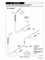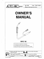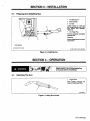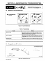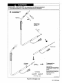
1
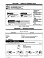
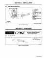
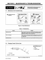
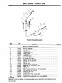
April
AUTO ARCJ~
1995
Form:
OM-112 934A
Effective With Serial No. KE-1 8
OWNERS
MANUAL
MWG 160
Air-Cooled Gun For GMAW And FCAW
160
Amperes,
60%
Welding
Duty Cycle Using CO2 Shielding
Gas
Feeds .023 And .030 in (0.6 And 0.8 mm) Hard Or Flux Cored Wires
Read and follow these instructions and all
blocks carefully.
Give this manual to the operator.
safety
Have
only
and qualified persons
service this unit.
trained
install, operate,
or
Call your distributor if you do not understand
the directions.
auto_arc 7/93
ST-800 300
For help, call your distributor
or:
MILLER Electric Mfg. Co., P.O. Box 1079,
WI 54912
414-734.9821
Appleton,
PRINTED IN USA
U
LIMITED WARRANTY
Effective January 1,1992
(Equipment
This limited warranty supersedes all
LIMITED WARRANTY
onginal
Subject
-
reIsil purchaser that
new
ited warranty is free of defects
in
with
a
serial number
previous manufacturers warranties
preface of KC
and is exclusive with
-
to the terms and conditions below, warrantS to its
equipment sold after the effective date of this lim
workmanship at the time it is shipped
from
Limited Warranty shall not
Manufacturer shall honor warranty claims
on
warranted
on
the warranty claim
equipment
listed below in
one
year after the
is sent to the
to:
warranty, if any.
2.
Consumable components; such as contact tips, cutting nozzles. contactors
and relays or pans that tall due to normal wear.
3.
Equipment that has been modified by any party other than manufacturer, or
equipment that has been Improperly installed, improperly operated or misused
based upon Industry standards. or equipment wflich has not had reasonable
warranty time peflods. All warranty time periods
equipment was delivered to the oflginal retail purchaser, or
equipment
apply
gines
the event of such a failure within me
stall on the date that the
Implied.
Items furnished by manufacturer, but manutactt~d by othere, such as en
or trade accessories. These items are coy~tmd by the manufacturers
1.
Within the warranty periods listed below, manufacturer will repair or replace any
warranted parts or components that fail due to such defects in matenal or workman
ship. Manufacturer must be flout ted in wflting within thirty (30) days of such detector
failure, at which time manufacturer will provide instructions
procedures to be followed.
other guarantees or warranties expressea or
Remote Controls
Accessory Kits
Replacement Parts
mateflal and
factory. THIS WARRANTY IS EXPRESSLY IN LIEU OF ALL OThER WAR
RANTIES. EXPRESS OR IMPLIED, INCLUDING THE WARRANTIES OF MER
CHANTABILITY AND FITNESS.
no
newer)
or
arid necessary maintenance, or equipment which has been used for operation
outside of the specifications for the equipment.
distflbutor.
5YeaisParts3YearsLabor
1.
MANUFACTURERS PRODUCTS ARE INTENDED FOR PURCHASE AND USE
BY COMMERCIAL/INDUSTRIAL USERS AND PERSONS TRAINED AND EXPE
RIENCED IN THE USE AND MAINTENANCE OF WELDING EQUIPMENT.
main power rectifiers
Original
3Yea,sPartsanuiLabor
2.
In the event of a warranty claim covered by this warranty, the exclusive remedies
shall be. at manufacturers option: (1) repair; or (2) replacement: or, where autho
rized in writing by manufacturer in appropriate cases. (3) the reasonable cost of re
Transformer/Rectifier Power Sources
Plasma Arc
Cutting
Semi-Automatic
Power Sources
sf0
Automatic Wire Feeders
2 Yeats
3.
the
Parts and Labor
Engine Driven Welding Generators
(NOTE: Engines are warranted separately by
for a period of two years.)
~Jr Compressors
1 YearParIs
4.
the
engine manufacturer
TO THE EXTENT PERMITTED BY LAW, THE REMEDIES PROVIDED HEREIN
ARE ThE SOLE AND EXCLUSIVE REMEDIES. IN NO EVENT SHALL MANUFAC
TURER BE LIABLE FOR DIRECT. INDIRECT, SPECIAL. INCIDENTAL OR CON
SEQUENTIAL DAMAGES (INCLUDING LOSS OF PROFIT), WHETHER BASED
ON CONTRACT. TORT OR ANY OTHER LEGAL THEORY.
and Labor
Motor Driven Guns
-
-
Process Controllers
-
Wat& Coolant
-
HFUnits
-
Grids
-
Spot
-
Load Banks
-
SDX Transformers
-
Running Gear/Trailers
Field Options
(NOTE: Field options are covered under the limited warranty for
maining warranty penod of the product they are installed in. or for
whichever is greater.)
mum of one year
-
or replacement at an authorized service station: or (4) payment of or credit for
purchase pnce (less reasonable depreciation based upon actual use) upon re
turn of the goods at customers risk and expense. manufacturers option of repair or
replacement will be FOB., Factory at Appleton. Wisconsin. or FOB. at an autho
rized service facility as determined by manufacturer. Therefore no compensation or
reimbursement for transportation costs of any kind Will be allowed.
pair
Robots
ANY EXPRESS WARRANTY NOT PROVIDED HEREIN AND ANY IMPLIED WAR
RANTY~ GUARANTY OR REPRESENTATION AS TO PERFORMANCE. A~D ANY
REMEDY FOR BREACH OF CONTRACT TORT OR ANY OTHER LEGAL
Systems
THEORY WHICH, BUT FOR THIS PROVISION. MIGHT ARISE BY IMPUCATION.
OPERATION OF LAW, CUSTOM OF TRADE OR COURSE OF DEAUNG. IN
CLUDING ANY IMPLIED WARRANTY OF MERCHANTABILITY OR FITNESS
FOR PARTICULAR PURPOSE. WITH RESPECT TO ANY AND ALL EQUtPMENT
FURNISHED BY MANUFACTURER IS EXCLUDED AND DISCLAIMED BY MAN
UFACTURER.
Welders
the re
a mini
Some stales in the U.S.A. do not allow limitations of how long an implied warranty
lasts, or the exclusion of incidental, indirect, special or consequential damages, so
the above limitation
cific
5.
6 Months
6.
90
In
Days
legal rights,
or
exclusion may not apply to you. This warranty provides spe
rights may be available, but may vary from state io state.
and Other
Batteries
-
MIG Guns/TIG Torches
-
Plasma
Canada. legislation
in some
provinces provides for
certain additional warranties
remedies Other than as stated herein, and to the extent that they may not be
waived, the limitations and exclusions set Out above may not apply. This Limited
Warranty provides specific legal flghts. and other rights may be available, but may
vary from province to province.
or
Parts and Labor
Cutting Torches
I_U
I
RECEIVING-HANDLING
Unpacking equipment, check carton for any damage that may have occurred during shipment. Fife any claims for loss or damage
delivering carrier. Assistance for filing or settling Claims may be obtained from distributor and/or equipment manufacturers
Transportation Department.
Before
with the
When
requesting information
Use the
or
about this
equipment, always provide
Model
Designation
and Serial
or
Style
Number.
following spaces to record Model Designation and Serial or Style Number of your unit. The information is located on the rating label
nameplate.
Model
__________
Serial
or
Style
No,
Date of Purchase
brand_acct 9/93
SAFETY PRECAUTIONS FOR GMAW GUNS
WARNING
AA
GMAW WELDING
be hazardous.
can
PROTECT YOURSELF AND OTHERS FROM POSSIBLE SERIOUS INJURY OR DEATH. KEEP CHILDREN
AWAY. PACEMAKER WEARERS KEEP AWAY UNTIL CONSULTING YOUR DOCTOR.
In welding, as in most jobs, exposure to certain hazards occurs. Welding is safe when precautions are taken. The
safety information given below is only a summary of the more complete safety information found in the wire feeder
and welding power source Owners Manuals. Read and follow all safety precautions.
HAVE ALL INSTALLATION,
OPERATION, MAINTENANCE, AND REPAIR WORK PERFORMED ONLY BY
QUALIFIED PEOPLE.
ELECTRIC SHOCK
kill.
ARC RAYS
2.
3.
Do not touch live electrode
4.
Repair or replace worn, damaged, or cracked
gun or cable insulation.
Turn off welding power source before changing
5.
Always
can
dry insulating gloves.
Insulate yourself from work and ground.
1.
wear
or
electncai parts.
p
~
Wear welding helmet with correct shade of filter.
2.
Wear correct eye and body protection.
Cover exposed skin with spatter-resistant
3.
clothing.
Al
HOT SURFACES
tip or gun parts.
Keep all covers and handle securely in place.
2.
3.
Protect hot metal from contact
NOISE
FUMES AND GASES
to your health.
can
Keep
2.
Ventilate area,
3.
Read Material
Safety Data Sheets (MSDSs) and
manufacturers
instructions for material used.
breathing
or use
damage hearing;
can
1.
Check for noise level limits
specified by OSHA.
2.
Use approved
level is high.
3.
Warn others
device.
ear
can cause
Do not weld
near
Do not weld
on
3.
Watch for fire;
fire
or
plugs
nearby
WELDING WIRE
1.
by others.
SOME
noisy.
your head out of the fumes.
2.
touching.
APPLICATIONS, SUCH AS PULSING, are
be hazardous I
1.
WELDING
burn skin.
can
Allow gun to cool before
Do not touch hot metal.
1.
contact
6.
burn eyes and skin.
can
1.
exceeding
or ear
those
muffs If noise
about noise hazard.
can
puncture
cause
wounds.
explosion.
1.
flammable mateflal.
closed containers.
Keep hands and body away
trigger is pressed.
from gun
tip
when
keep extinguisher nearby.
EMF INFORMATION
NOTE ~
I
Considerations About We Iding And The Effects Of Low
Fields
Frequency
Electric And
Magnetic
The
To reduce
of the U.S.
following is a quotation from the General Conclusions Section
Congress, Office of Technology Assessment, Biological
Effects of Power Frequency Electric & Magnetic Fields
Background Paper, OTA-BP-E-53 (Washington, DC: U.S.
Government Printing Office. May 1989):.
there is now a very
large volume of scientific findings based on experiments at the
procedures:
.
magnetic fields
in the
workplace,
1.
Keep cables close together by twisting
2.
Arrange
3.
Do not coil
4.
Keep welding power
practical.
5.
Connect work clamp to workpiece
cables to
one
or
use
taping
the
following
them.
side and away from the operator.
.
cellular level and from studies with animals and
people which clearly
establish that low
frequency magnetic fields can interact with, and
produce changes in, biological systems. While most of this work is
of very high quality, the results are complex. Current scientific
understanding does not yet allow us to interpret the evidence in a
single coherent framework. Even more frustrating, it does not yet
allow us to draw definite conclusions about questions of possible
risk or to offer clear science-based advice on strategies to minimize
or avoid potential risks.
or
drape cables around
source
the
body.
and cables
as
as
far away
as
close to the weld
as
possible,
About Pacemakers:
The
above
procedures are among those also
pacemaker wearers. Consult your
recommended for
complete information.
normally
doctor for
modlo.l 4/93
sri 7/93
SAFETY INFORMATION
SECTION 1
modl.1 8193
U
,
safety messages throughout this manual.
Obey
safety messages
all
Learn the
U
1
Read all
meaning
to avoid
injury.
of WARNING and CAUTION.
2
2
\
I
:I~II~e.I
ELECTRIC SHOCK
Donottou
kill
iveeltlcalparts.
input power
servicing.
Disconnect
installing
can
or
before]]
2
SignalWord
a
Keepawaytrommovingpana.
I
means possible minor
injury or equipment damage can
happen.
Keep elf panels and
I
3
Statement Of Hazard And
Result
4
Safety
5
Hazard
6
Safety Banner
Injure,
covets
closed
WtISfl ~
I
READ SAFETY BLOCKS at start of
SectIon 3.1 before proceeding.
WARNING
Instructions To Avoid
Hazard
Read
Turn Off switch when using high frequency.
safety blocks for
1-1.
Safety
each sym
NOTE
Special
ation
Figure
Symbol (If Available)
bol shown.
7
~
NOTE
Symbol
CAUTION
can
5
6
Alert
means possible death
orsenousinjurycanhappen.
MOVING PARTS
$~
~
Safety
WARNING
A~ CAUTION
~I1
1
instructions for best oper
not related to
safety.
Information
SECTION 2- SPECIFICATIONS
Table 2-1
-
Welding
Gun
Specifications
Rated
Description
160 Amperes
Output
Using CO2 Shielding Gas
Duty Cycle
See
Wire Diameter
.023 And .030 in
Weight
lOft Gun
2-1.
Figure
Air-Cooled
2-1
(0.6 And 0.8 mm) Hard Or Flux-Cored Wires
Net: 2.8 lb
(1.3 kg); Ship: 5.4 lb (2.4 kg)
Duty Cycle
£~
CAUTION
WELDING LONGER THAN RATED DUTY CYCLE
Do not weld at rated load
longer
c an
damage
gun and void warranty.
than shown below.
wfwam8.1 8/93
Definition
10
Duty Cycle is percentage of 10
minutes that gun can weld at
rated load without overheating.
Minutes
60%
Duty Cycle At 160 Amperes Using CO2 Gas
30%
Duty Cycle
At 160
Amperes Using Mixed Gases
g~g~ ~
4 mm
6 mm
3 mm
Figure
OM-112 934
Page
1
2-1.
Duty Cycle
7 mm
sbl.5 8193
SECTION 3-INSTALLATION
3-1.
Preparing
And
Installing
Gun
1
Gun
2
DrIve
3
Gun End
Securing
Nut
Assembly
Loosen securing nut. Insert gun
through opening until It bot
end
against
Tighten nut.
toms
4
Gun
drive
assembly.
Trigger Plug
Insert Into receptacle and
threaded collar.
tighten
Close door.
2
1
See wire feeder manual for thread
ing procedure.
Tools Needed:
~ 5/l6in
Ref. ST-151 357/ Ref. ST-149 629-C
Figure
3-1.
installIng
Gun
SECTION 4- OPERATION
READ SAFETY BLOCKS at beginning
of manual before proceeding.
4-1.
Operating
The Gun
1
Trigger
Switch
When pressed, energized wire
feeds and shielding gas flows.
1
Ref. S-0621-C
Figure
4-1.
Using Gun Switch
OM-112 934
Page
2
SECTION 5- MAINTENANCE & TROUBLESHOOTING
4A
5-1.
READ SAFETY BLOCKS at beginning
of manual before proceeding.
WARNING
Ma intenance And
Turn Off all power before
Troubleshooting
Each
-~
Spool Of Wire
3 Months
maintaining.
Sec~on~
~ Bk~ut
5 2
Control Cord
~
~zTh~I
Gas Hose
Figure
Troubleshooting
Trouble
Remedy
.
n ot
Wire is not
Gun Cable
5-1. Routine Maintenance
Table 5-1.
Wire does
,
Check contact tip. Check for kinks in gun cable. Check trigger connection at
welding power source/wire feeder. Have nearest Factory Authorized Service
Station/Service Distributor check gun trigger switch.
feed.
Check contact tip. Check trigger connection at welding power source/wire feed
Have nearest Factory Authorized Service Station/Service Distributor check
energized.
er.
gun trigger switch.
Wire feeds
5-2.
Check contact tip. Check for kinks in gun cable. Blow out liner and gun casing.
unevenly.
Ch anging Contact
Tip And Liner
Turn off welding power source/wire
feeder. Cut off wire at nozzle.
1
Nozzle
2
Contact
lip
3
Contact
lip Adapter
Tools Needed:
~:?
Rel. ST-149 326-A
Figure
OM-112 934
Page 3
5-2.
Changing
Contact
Tip
SECTION 6
PARTS LIST
14
16
3
18
19
Ref. ST-lb
FIgure
Item
No.
Part
No.
1
110793
110795
Complete Assembly
Description
Figure
2
6-1.
6-1.
HANDLE ASSEMBLY
3
4
110779
5
110781
6
128878
7
118571
8
8
112743
112751
9
112747
9
.113018
113022
9
113020
10
110794
11
12
080565
110792
13
110797
14
167440
15
110784
16
Quantity
Complete Assembly
TUBE, head (consisting of)
110780 ....NUT,MlOxl
9
832-D
JACKET, head tube
STOP, nozzle
ADAPTER, head tube nozzle
SPRING, nozzle
TIP, contact .024 (.6 mm)
TIP, contact .030 (.8 mm)
NOZZLE, slip type 1/2 orifice
NOZZLE, slip type 3/8 orifice
NOZZLE, spot flat
NOZZLE, spot
TRIGGER SWITCH ASSEMBLY
TERMINAL, frict uninsul fern 22-l8ga
1
1
2
1
1
1
1
1
1
1
1
1
1
1
2
079974
CABLE, lOft
SLEEVE, rubber
LINER, monocoil .023-.035 wire lOft (consisting of)
COLLET, liner .023-.030 wire
O-RING,1/2lDx.103
2
17
110796
CONNECTOR, gun/feeder
1
18
079878
CONNECTOR & PINS, (consisting of)
CONNECTOR, circ pin push-in 14-l8ga Amp 66359-6
CONNECTOR, circ clamp str rlf sz 11 Amp 206062-4
4
079 535
19
048834
OPTIONAL
BE SURE TO PROVIDE MODEL AND SERIAL NUMBER WHEN ORDERING REPLACEMENT PARTS.
OM-112 934 Page 5
1
1
1
1
1
1
CAUTION
AA
FLYING METAL CHIPS AND DIRT
Point gun away from
people
and in
a
can cause
injury
safe direction when
blowing
and
damage equipment.
out with
compressed air.
Turn off welding power
sourcelwlre feeder.
Head
Remove nozzle,
contact tip, and
liner collet.
Remove liner.
Gun/Feeder
Connector
~4I#
~ow
To Reassemble Gun:
out
Install contact
gun casing.
Insert
new
tip.
liner.
Install collet onto liner and tighten
into gun/feeder connector using
wrench.
Tools Needed:
Cut liner off near collet so that liner
end is as close to drive rolls as pos
sible without touching.
Install nozzle.
3/8 in
Ref. ST-155 509
Figure
5-3.
Changing
Liner
OM-112 934 Page 4
Form:
April1995
AUTO ARCJ
OM-112934A
-
Effective With Serial No. KE-18
OWNERS
MAN UAL
MWG 160
Air-Cooled Gun For GMAW And FCAW
160
Amperes,
60%
Welding
Duty Cycle Using CO2 Shielding Gas
Feeds .023 And .030 in
(0.6 And
Read and follow these instructions and all
blocks carefully.
0.8
mm) Hard Or Flux Cored Wires
Give this manual to the operator.
safety
Have
auto_arc 7/93
only
trained and qualified persons
or service this unit.
install, operate,
For help, call your distributor
Call your distributor if you do not understand
the directions.
or:
ST-800 300
MILLER Electric
Appleton, WI 54912
Mfg. Co.,
P.O. Box 1079,
414-734-9821
PRINTED IN ~SA
I
I
LIMITED WARRANTY
(Equipment
ThIs limited warranty supersedes all
with
Effective January 1, 1992
serial number preface of KC
a
previous manufacturers
warranties and is exclusive with
LIMITED WARRANTY Subject to the terms end conditions below, warrants to its
original retail purchaser that new equipment sold after the effective date of this tim-
Remote Controls
-
Accessory Kits
-
Umited
R
newer)
other guarantees or warranties
-
-
warranty is free of defects in material and workmanship at the time it is shipped
from factory. THIS WARRANTY IS EXPRESSLY IN LIEU OF ALL OTHER WAR
RANTIES, EXPRESS OR IMPLIED. INCLUDING THE WARRANTIES OF MERited
no
or
expressed
or
implied.
lacement Parts
Warranty
shell not
apply
to:
CHANTABILITY AND FITNESS.
1.
Within the warranty perioda listed below, manufacturer will repair or replace any
warranted parts or components that fail due to such defects in matenal or workman
ship.
Manufacturer must be notified in
Items furnished by manufacturer, but manufactured
gines or trade accessories. These
warranty, if any.
by others, such as en
by the manufacturers
Hems are covered
writing within thirty (3C) days of auth defect or
the warranty claim
2.
Consumable components; such as contact tips,
and relays or pans that fail due to normal wear.
Manufacturer shall honor warranty cleima on warranted equipment listed below in
the event of such a failure within the warranty time periods. All warranty time periods
start on the dats that the equipment was delivered to the onginal retail purchaser, or
3.
Equipment that has been modified by any party other than manufacturer, or
equipment that has been improperfy installed. improperly operated or misused
based upon industry standards, or equipment which has not had reasonable
and necessary maintenance, or equipment which has been used for operation
outside of the specifications for the equipment.
failure, at which time manufacturer will provide instructions
procedures
one
1.
year after the
3,
equipment
a sent to the diatributor.
cutting nozzles.
contsctors
5YesreParts3YesreLabor
-
2.
on
to be followed.
Original
MANUFACTURERS PRODUCTS ARE INTENDED FOR PURCHASE AND USE
BY COMMERCIAL/INDUSTRIAL USERS AND PERSONS TRAINED AND EXPE
RIENCED IN THE USE AND MAINTENANCE OF WELDING EQUIPMENT.
main power rectifiers
3Yeara Parta
and Labor
In the event of a warranty claim covered by this warranty, the exclusive remedies
shalt be. at manufacturers option: (1) repair: or (2) replacement: or, where autho
rized in writing by manufacturer in appropnate cases. (3) the reasonable cost of re
-
Transformer/Rectifier Power Sources
-
Plasma Arc
-
Semi-Automatic and Automatic Wire Feeders
-
Robots
Cutting
Power Sources
or replacement stan authoflzed service station; or (4) payment of or credit for
purchase price (less reasonable depreciation based upon actual use) upon re
turn of the goods at customers risk and expense. manufacturers option of repair or
replacement will be FOB., Factory at Appleton, Wisconsin, or FOB. at an autho
rized aervice facility as determined by manufacturer. Therefore no compensation or
reimbursement for transportation costs of any kind wilt be allowed.
pair
the
Parts end Labor
2 Years
-
Engine Driven Welding Generators
(NOTE: Engines are warranted separately by
fore penod of two yeara.)
-
Air
the
engine
manufacturer
TO THE EXTENT PERMITTED BY LAW, THE REMEDIES PROVIDED HEREIN
ARE THE SOLE AND EXCLUSIVE REMEDIES. IN NO EVENT SHALL MANUFAC
TURER BE LIABLE FOR DIRECT, INDIRECT, SPECIAL. INCIDENTAL OR CON
SEQUENTIAL DAMAGES (INCLUDING LOSS OF PROFIT), WHETHER BASED
ON CONTRACT, TORT OR ANY OTHER LEGAL THEORY.
Compressors
tYearPertssndLsbor
4.
Motor Driven Guns
-
-
Process Controllers
-
Water Coolant
-
HFUnlts
-
Grids
-
Spot Wetdere
-
Load Banks
-
SDX Trsnsforniers
ANY EXPRESS WARRANTY NOT PROVIDED HEREIN AND ANY IMPUED WAR
RANT,, GUARANTY OR REPRESENTATION AS TO PERFORMANCE. AND ANY
REMEOY FOR BREACH OF CONTRACT TORT OR ANY OTHER LEGAL
THEORY WHICH. BUT FOR THIS PROVISION, MIGHT ARISE BY IMPUCATION,
OPERATION OF LAW, CUSTOM OF TRADE OR COURSE OF DEALING. IN
CLUDING ANY IMPLIED WARRANTY OF MERCHANTABIUTY OR FITNESS
FOR PARTICULAR PURPOSE. WITH RESPECT TO ANY AND ALL EQUIPMENT
FURNISHED BY MANUFACTURER IS EXCLUDED AND DISCLAIMED BY MAN
-
Running Gear/Trailers
UFACTURER.
-
Field
Systems
Options
(NOTE: Field options
are
Some states in the U.S.A. do
not allow limitations of how tong an implied warranty
of incidental. indirect, special or consequential damages, so
the above limitation or exclusion may not apply to you. This warranty provides ape
cific legal rights, and other rights may be svailable, but may vary from state to state.
covered under the limited warranty for the re
are installed in. or for a mini
lasts,
maining warranty period of the product they
mum
5.
6 Months
6.
90
of
one
year
whichever is
greater.)
or the exclusion
Bstteries
In Canada.
Days
-
MIG Guns/TIG Torches
-
Plasma
Cuning
legislation
in
some
provinces provides for certain additional
warranties
remedies other than as stated herein, and to the extent that they may not be
waived, the limitations and exclusions set out above may not apply. This Umited
or
Parts and Labor
Warranty provides specific legal rights,
vary from province to province.
Torches
end other
rights
may be available, but may
-I-c
FT
RECEIVING-HANDLING
Unpacking equipment, check carton for any damage that may have occurred during shipment. File any claims for losS or damage
delivering carrier. Assistance for filing or settling claims may be obtained from distributor and/or equipment manufacturers
Transportation Department.
Before
with tha
When
requesting
following
nameplate.
Use the
or
information about this
equipment, always provide
spaces to record Model
Designation
and Serial
or
Model
Designation
and Serial
or
Style Number.
Style Number of your unit. The information
is located
on
the
rating label
Model
_________
Serial
or
Style
No.
Date of Purchase
bran&,acct 9/93
SAFETY PRECAUTIONS FOR GMAW GUNS
WARNING
AA
GMAW WELDING
can
be hazardous.
PROTECT YOURSELF AND OTHERS FROM POSSIBLE SERIOUS INJURY OR DEATH. KEEP CHILDREN
AWAY. PACEMAKER WEARERS KEEP AWAY UNTIL CONSULTING YOUR DOCTOR.
In welding, as in most jobs, exposure to certain hazards occurs. Welding is safe when precautions are taken. The
safety information given below is only a summary of the more complete safety information found in the wire feeder
and welding power source Owners Manuals. Read and follow all safety precautions.
HAVE ALL INSTALLATION, OPERATION, MAINTENANCE, AND REPAIR WORK PERFORMED ONLY BY
QUALIFIED PEOPLE.
ELECTRIC SHOCK
can
kill.
ARC RAYS
2.
dry insulating gloves.
Insulate yourself from work and ground.
3.
Do not touch live electrode
1.
4.
Always
Repair
wear
or
replace
worn,
or
electflcal parts.
damaged,
or
burn eyes and skin.
can
1.
Wear welding helmet with correct shade of filter.
2.
Wear correct eye and body protection.
Cover exposed skin with spatter-resistant
3.
clothing.
cracked
___________
gun
5.
or
cable insulation.
welding power source before changing
tip or gun parts.
Keep all covers and handle securely in place.
Turn off
contact
6.
HOT SURFACES
S
~
Allow gun to cool before
2.
Do not touch hot metal.
3.
Protect hot metal from contact
NOISE
FUMES AND GASES
can
2.
3.
by others.
SOME
damage hearing;
can
noisy.
Keep your head out of the fumes.
Ventilate area, or use breathing device.
1.
Read Material Safety Data Sheets (MSDSs) and
manufacturers instructions for mateflal used.
2.
Check for noise level limits
exceeding those
specified by OSHA.
Use approved ear plugs or ear muffs if noise
level is high.
Warn others nearby about noise hazard.
3.
WELDING
touching.
APPLICATIONS, SUCH AS PULSING, are
be hazardous
to your health.
1.
burn skin.
can
1.
can cause
1.
Do not weld
near
2.
Do not weld
on
3.
Watch for fire;
fire
or
WELDING WIRE
wounds.
explosion.
1.
flammable matenal.
closed containers.
can
puncture
cause
Keep hands and body away from gun tip
tngger is pressed.
when
keep extinguisher nearby.
EMF INFORMATION
Considerations About
NOTE
Magnetic
Welding
And The Effects Of Low
The
To
of the U.S.
procedures:
following is a quotation from the General Conclusions Section
Congress, Office of Technology Assessment, Biological
Effects of Power Frequency Electric & Magnetic Fields
Backg round Paper, OTA-BP.E-53 (Washington, DC: U.S.
there is now a very
Government Printing Office, May 1989): ~.
large volume of scientific findings based on experiments at the
cellular level and from studies with animals and people which clearly
.
potential
risks.
Electric And
magnetic
1.
Keep cables
Arrange
fields in the
close
cables to
workplace,
together by twisting
one
or
use
taping
the
following
them.
side and away from the operator.
.
frequency magnetic fields can interact with, and
produce changes in, biological systems. While most of this work is
of very high quality, the results are complex. Current scientific
understanding does not yet allow us to interpret the evidence in a
single coherent framework. Even more frustrating, it does not yet
allow us to draw definite conclusions about questions of possible
risk or to offer clear science-based advice on strategies to minimize
avoid
reduce
2.
3.
Do not coil
4.
Keep welding power
practical.
5.
Connect work clamp to workpiece
establish that low
or
Frequency
Fields
or
drape cables
around the
source
body.
and cables
as
as
far away
as
close to the weld
as
possible.
About Pacemakers:
The
above
procedures are among those also normally
pacemaker wearers. Consult your doctor for
recommended for
complete information.
modlO.1 4193
sr7 7/93
SECTION 1
-
SAFETY INFORMATION
modl.1 2/93
Read all safety messages
throughout this
Obey all safety messages
to avoid
Learn the
meaning
manual.
injury.
of WARNING and CAUTION.
1
Safety
Alert
2
Signal
Word
2
2
WARNING
or
:1~1l~ei~U
~-..
ELECTRIC SHOCK
can
4~
3
CAUTION
kill.~
Installing
or
input power
servicing.
KeeQ away
can
covers closed
3
Statement Of Hazard And
Result
4
Safety
5
Hazard
6
Safety
5
READ SAFETY BLOCKS at start
SectIon 3-1 before proceeding.
6
oil
~
Turn Off switch when
Instructions To Avoid
Hazard
using high frequency.
1-1.
Safety
Banner
NOTE
Special instructions for best oper
ation
Figure
Symbol (If Available)
Read safety blocks for each sym
bol shown.
7
NOTE
possible death
happen.
can
means possible minor
injury or equipment damage can
happen.
Injure.
moving pans.
IrOm
Ksep all panels and
when operating.
before
means
injury
CAUTION
MOVING PARTS
Do not toucfl live electncai pans.
DIsconnect
serious
Symbol
not related to
safety.
Information
SECTION 2- SPECIFICATIONS
Table 2-1.
Welding
Gun
Specifications
Description
Amperes Using CO2 Shielding Gas
Air-Cooled
Rated Output
160
Duty Cycle
See Figure 2-1
Wire Diameter
.023 And .030 in (0.6 And 0.8 mm) Hard O~ Flux-Cored Wires
Weight
10 ft Gun
2-1.
Net: 2.8 lb
(1.3 kg); Ship:
5.4 lb
(2.4 kg)
Duty Cycle
£~
CAUTION
WELDING LO NGER THAN RATED DUTY CYCLE
Do not weld at r ated load
longer
can
damage
gun and void warranty.
than shown below.
wtwam8.1 8/93
DefInitIon
Duty Cycle is percentage
minutes that gun
rated toad without
can
of 10
weld at
overheating.
Minutes
30%
Figure
OM-112 934 Page 1
2-1.
Duty Cycle
Duty Cycle
At 160
Amperes Using Mixed Gases
SECTION 3- INSTALLATION
3-1.
Preparing
And
Installing Gun
1
Gun
2
Drive
3
Gun End
Securing
Nut
Assembly
Loosen securing nut. Insert gun
end through opening until it bot
toms against drive assembly.
Tighten
4
nut.
GunTnggerPlug
Insert Into receptacle and
threaded collar.
tighten
Close door.
1
2
See wire feeder manual for thread
ing procedure.
Toots Needed:
~
5/16 in
Ref. ST-151 357/Ref. ST-149 629-C
Figure
3-1.
Installing
Gun
SECTION 4- OPERATION
~pf~
4-1.
Operating
~
READ SAFETY BLOCKS at beginning
of manual before proceeding.
The Gun
1
Trigger
When
Switch
pressed, energized wire
feeds and
shielding
gas flows.
Ref. S-0621-C
Figure
4-1.
Using Gun Switch
OM-112 934 Page 2
SECTION 5- MAINTENANCE & TROUBLESHOOTING
READ SAFETY BLOCKS at beginning
of manual before proceeding.
5-1.
4
Maintenance And
Troubleshooting
Each
Turn Off all power before
Spool
-.~
Of Wire
3 Months
maintaining.
B~w Out
5-2
Control Cord
H~
~~~rzTh~I
Gas Hose
Figure
Gun Cable
5-1. Routine Maintenance
Table 5-1.
Troubleshooting
Trouble
Remedy
Wire does not feed.
tip. Check for kinks in gun cable. Check trigger connection at
power source/wire feeder. Have nearest Factory Authorized Seniice
Station/Service Distributor check gun trigger switch.
Check contact
welding
Wire is not
energized.
Check contact tip. Check trigger connection at welding power source/wire feed
er. Have nearest Factory Authorized Service Station/Service Distributor check
gun trigger switch.
Wire feeds
unevenly.
Check contact tip. Check for kinks in gun cable. Blow out liner and gun casing.
5-2.
Changing
Contact
Tip
And Liner
Turn oft welding power source/wire
feeder. Cut off wire at nozzle.
1
Nozzle
2
Contact
3
Contact Tip Adapter
Tip
Tools N eeded:
~Z?
Ref. ST.149 326-A
Figure
OM-112 934
Page
3
5-2.
Changing
Contact
Tip
SECTION 6
PARTS LIST
14
16
17
3
18
19
Ret. ST11O
Figure
Part
No.
Item
No.
1
110793
110795
3
6
110780
110779
110781
128878
7
118571
8
8
112743
9
112747
9
.113018
9
.113022
9
.113020
4
5
112751
110 794
.
.
080 565
11
110 792
110 797
13
167 440
110 784
079 974
110 796
079 878
079 535
048 834
19
Complete Assembly
Description
Figure
2
6-1.
6-1.
HANDLE ASSEMBLY
TUBE, head (consisting of)
....NUT,MlOxl
JACKET, head tube
STOP, nozzle
ADAPTER, head tube nozzle
SPRING, nozzle
TIP, contact .024 (.6 mm)
TIP, contact .030 (.8 mm)
NOZZLE, slip type 1/2 orifice
NOZZLE, slip type 3/8 orifice
NOZZLE, spot flat
NOZZLE, spot
TRIGGER SWITCH ASSEMBLY
TERMINAL, frict uninsul fern 22-l8ga
CABLE, lOft
SLEEVE, rubber
LINER, monocoil .023-.035 wire lOft (consisting of)
COLLET, liner .023-.030 wire
O-RING,1/2IDx.103
CONNECTOR, gun/feeder
CONNECTOR & PINS, (consisting of)
CONNECTOR, circ pin push-in 14-l8ga Amp 66359-6
CONNECTOR, circ clamp str rlf sz 11 Amp 206062-4
OPTIONAL
Page
5
Quantity
Complete Assembly
BE SURE TO PROVIDE MODEL AND SERIAL NUMBER WHEN ORDERING REPLACEMENT PARTS.
OM-112 934
632~D
1
1
2
1
1
1
1
1
1
1
1
1
1
1
2
1
1
1
1
2
1
1
4
1
CAUTION
AA
FLYING METAL CHIPS AND DIRT
Point gun away from
people
and in
a
can cause
safe direction wtien
injury
blowing
and
damage equipment.
out with
compressed air.
Turn off welding power
source/wire feeder.
Head Tube.
Remove nozzle,
tip, and
liner collet.
contact
//
11/
I
Remove liner.
Gun/Feeder
Connector
I
~ow
To Reassemble Gun:
out
gun casing.
Install contact tip.
Insert
new
liner.
Install collet Onto liner and
into
gun/feeder
connector
tighten
using
wrench.
Tools Needed:
Cut liner off near collet so that liner
end is as close to drive rolls as pos
sible without touching.
Install nozzle.
-~ 3/8in
Ref. ST-155 509
Figure
5-3.
Changing
Liner
OM-112 934
Page
4