1
REVISION 0
AUG. 1999
COPYRIGHT © 1999 CANON INC.
FY8-13GB-000
CANON NP6512/6612/7120/7130/7130F REV.0 AUG. 1999 PRINTED IN JAPAN (IMPRIME AU JAPON)
IMPORTANT
THIS DOCUMENTATION IS PUBLISHED BY CANON INC., JAPAN, TO SERVE AS A SOURCE
OF REFERENCE FOR WORK IN THE FIELD.
SPECIFICATIONS AND OTHER INFORMATION CONTAINED HEREIN MAY VARY SLIGHTLY
FROM ACTUAL MACHINE VALUES OR THOSE FOUND IN ADVERTISING AND OTHER
PRINTED MATTER.
ANY QUESTIONS REGARDING INFORMATION CONTAINED HEREIN SHOULD BE DIRECTED
TO THE COPIER SERVICE DEPARTMENT OF THE SALES COMPANY.
THIS DOCUMENTATION IS INTENDED FOR ALL SALES AREAS, AND MAY CONTAIN INFORMATION NOT APPLICABLE TO CERTAIN AREAS.
COPYRIGHT © 1999 CANON INC.
Printed in Japan
Imprimé au Japon
Use of this manual should be strictly supervised to avoid disclosure of confidential
information.
Prepared by
OFFICE IMAGING PRODUCTS TECHNICAL SUPPORT DIVISION
CANON INC.
5-1, Hakusan 7-chome, Toride-shi, Ibaraki 302-8501 Japan
COPYRIGHT © 1999 CANON INC.
CANON NP6512/6612/7120/7130/7130F REV.0 AUG. 1999 PRINTED IN JAPAN (IMPRIME AU JAPON)
INTRODUCTION
This service manual has been prepared for NP6512, NP6612, NP7120, NP7130, and
NP7130F, providing basic information used for servicing the machines in the field so as to
ensure their quality and performance.
This service manual consists of the following chapters:
Chapter 1
General Description introduces the machine's features, specifications,
names of parts, and how originals are reproduced.
Chapter 2
Basic Operation explains how copies are made on a step-by-step basis.
Chapter 3
Exposure System discusses the principles of operation used for the
machine's exposure system. It also explains the timing at which exposurerelated mechanisms are operated, and shows how they may be
disassembled/assembled and adjusted.
Chapter 4
Image Formation System discusses the principles of operation used for the
machine's image formation system. It also explains the timing at which image
formation-related mechanisms are operated, and shows how they may be
disassembled/assembled and adjusted.
Chapter 5
Pick-Up/Feeding System discusses the principles of operation used for the
machine's pickup/feeding system. It also explains the timing at which pickup/
feeding-related mechanisms are operated, and shows how they may be
disassembled/assembled and adjusted.
Chapter 6
Fixing System discusses the principles of operation used for the machine's
fixing system. It also explains the timing at which fixing-related mechanisms
are operated, and shows how they may be disassembled/assembled and
adjusted.
Chapter 7
Externals/Auxiliary Mechanisms discusses the principles of operation used
for the machine's externals/auxiliary mechanisms. It also explains the timing
at which auxiliary mechanism-related mechanisms are operated, and shows
how they may be disassembled/assembled and adjusted.
Chapter 8
ADF explains the principles of operation of the ADF in view of electrical and
mechanical functions and in relation to their timing of operation. It also shows
how the unit may be disassembled/assembled and adjusted.
Chapter 9
Installation introduces requirements for the site of installation, and shows
how the machine may be installed using step-by-step instructions.
Chapter 10 Maintenance and Servicing provides tables of periodically replaced parts and
consumables/durables and scheduled servicing charts.
Chapter 11 Troubleshooting provides tables of maintenance/inspection, standards/
adjustments, and problem identification (image fault/malfunction).
Appendix contains a general timing chart and general circuit diagrams.
COPYRIGHT © 1999 CANON INC.
CANON NP6512/6612/7120/7130/7130F REV.0 AUG. 1999 PRINTED IN JAPAN (IMPRIME AU JAPON)
i
The following rules apply throughout this Service Manual:
1. Each chapter contains sections explaining the purpose of specific functions and the
relationship between electrical and mechanical systems with reference to the timing
of operation.
represents the path of mechanical drive—where a signal name
In the diagrams,
accompanies the symbol
, the arrow indicates the direction of the electric signal.
The expression “turn on the power” means flipping on the power switch, closing the
front door, and closing the delivery unit door, which results in supplying the machine
with power.
2. In the digital circuits, ‘1’ is used to indicate that the voltage level of a given signal is
“High,” while ‘0’ is used to indicate “Low.” (The voltage value, however, differs from
circuit to circuit.)
In practically all cases, the internal mechanisms of a microprocessor cannot be checked
in the field. Therefore, the operations of the microprocessors used in the machines
are not discussed: they are explained in terms of from sensors to the input of the DC
controller PCB and from the output of the DC controller PCB to the loads.
The descriptions in this Service Manual are subject to change without notice for
product improvement or other reasons, and major changes will be communicated in the
form of Service Information bulletins.
All service persons are expected to have a good understanding of the contents of this
Service Manual and all relevant Service Information bulletins and be able to identify and
isolate faults in the machine.
ii
COPYRIGHT © 1999 CANON INC.
CANON NP6512/6612/7120/7130/7130F REV.0 AUG. 1999 PRINTED IN JAPAN (IMPRIME AU JAPON)
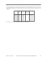
• This service manual covers the models shown in the following table. Be sure to have a
good understanding of the difference from model to model before referring to this
manual.
Model
Type
code
Default
ratio
NP6512
NP6612
NP7120
NP7120
NP7130
NP7130
NP7130F
TWA
TXA
PUB
PUC
NVF
PTZ
NVH
2R2E
2R2E
2R2E
2R2E
3R1E
2R2E
3R1E
ADF as
standard
√
√
Cassette
250 sheets
250 sheets
Universal
Universal
500 sheets
500 sheets
500 sheets
The notation “√” indicates that the item in question is available.
COPYRIGHT © 1999 CANON INC.
CANON NP6512/6612/7120/7130/7130F REV.0 AUG. 1999 PRINTED IN JAPAN (IMPRIME AU JAPON)
iii
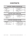
CONTENTS
CHAPTER 1 GENERAL DESCRIPTION
I.
II.
FEATURES ..................................1-1
SPECIFICATIONS .......................1-2
A. Copier ....................................1-2
B. ADF .......................................1-6
III. NAMES OF PARTS .....................1-8
A. External View ........................1-8
B. Cross Section ..................... 1-11
IV. USING THE MACHINE ............. 1-13
A. Control Panel...................... 1-13
B. User mode .......................... 1-15
V. ROUTINE MAINTENANCE BY THE
USER ........................................ 1-16
VI. IMAGE FORMATION ................ 1-19
A. Outline ................................ 1-19
CHAPTER 2 BASIC OPERATION
I.
BASIC OPERATIONS ..................2-1
A. Functional Construction ........2-1
B. Outline of Electrical
Circuitry .................................2-2
C. Basic Sequence of
Operations .............................2-3
D. Controlling the Main
Motor (M1) .............................2-5
E. Inputs to and Outputs from the
DC Controller ........................2-7
CHAPTER 3 EXPOSURE SYSTEM
I.
OPERATIONS ..............................3-1
A. Outline ...................................3-1
B. Varying the Reproduction
Ratio ......................................3-2
C. Lens Drive System ................3-3
D. Scanner Drive System ..........3-4
COPYRIGHT © 1999 CANON INC.
II.
EXPOSURE SYSTEM .................3-9
A. Controlling the Scanning
Lamp .....................................3-9
III. DISASSEMBLY/ASSEMBLY ..... 3-13
A. Scanner Drive Assembly .... 3-14
B. Lens Drive Assembly ......... 3-32
C. Exposure System ............... 3-38
CANON NP6512/6612/7120/7130/7130F REV.0 AUG. 1999 PRINTED IN JAPAN (IMPRIME AU JAPON)
v
CHAPTER 4 IMAGE FORMATION SYSTEM
I.
IMAGE FORMATION SYSTEM ...4-1
A. Outline ...................................4-1
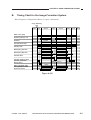
B. Timing Chart for the Image
Formation System .................4-3
C. Primary Charging Roller Bias
Control ...................................4-4
D. Controlling the Transfer Roller
Bias .......................................4-9
E. Controlling the Developing/
Separation Static Eliminator
Bias .................................... 4-12
F. Measuring the Density of
Originals ............................. 4-18
G. Controlling the Pre-Exposure
Lamp .................................. 4-24
H. Controlling the Side Blanking
Mechanism ......................... 4-26
II.
DEVELOPING ASSEMBLY
/CLEANING ASSEMBLY...........
A. Outline ................................
B. Detecting the Level of
Toner ..................................
C. Detecting Waste Toner .......
D. Primary Charging Roller
Cleaning Control ................
III. DISASSEMBLY/ASSEMBLY .....
A. Drum Unit ...........................
B. Transfer Charging
Assembly ............................
C. Blank Exposure ..................
D. Developing Assembly .........
4-27
4-27
4-28
4-30
4-31
4-33
4-34
4-38
4-39
4-43
CHAPTER 5 PICK-UP/FEEDING SYSTEM
I.
PICKUP/FEEDING SYSTEM.......5-1
A. Outline ...................................5-1
B. Controlling the Pickup
Roller .....................................5-2
C. Controlling the Movement of
Paper .....................................5-6
D. Detecting Jams .....................5-8
II.
DISASSEMBLY/ASSEMBLY .....
A. Pickup Assembly ................
B. Multifeeder Assembly .........
C. Feeding Assembly ..............
D. Registration Roller
Assembly ............................
E. Delivery Assembly ..............
5-13
5-14
5-21
5-24
5-25
5-30
CHAPTER 6 FIXING SYSTEM
I.
vi
OPERATIONS ..............................6-1
A. Outline ...................................6-1
B. Controlling the Fixing
Temperature ..........................6-3
COPYRIGHT © 1999 CANON INC.
II.
DISASSEMBLY/ASSEMBLY ........6-9
A. Fixing Assembly ................. 6-10
CANON NP6512/6612/7120/7130/7130F REV.0 AUG. 1999 PRINTED IN JAPAN (IMPRIME AU JAPON)
CHAPTER 7 EXTERNALS/AUXILIARY MECHANISMS
I.
II.
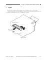
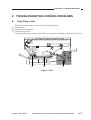
FANS ............................................7-1
POWER SUPPLY SYSTEM .........7-3
A. Outline of the Power Supply
System ..................................7-3
B. Power Supply Circuit .............7-4
C. Detecting an Error on the Composite Power Supply PCB .....7-6
D. Protecting the Power Supply
Circuit ....................................7-6
III. DISASSEMBLY/ASSEMBLY ........7-7
A. External Covers .....................7-8
B. Control Panel...................... 7-15
C. Copyboard Glass ............... 7-16
D. Main Motor/Main Drive Assembly ....................................... 7-17
E. Electrical System ............... 7-21
CHAPTER 8 ADF
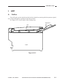
I.
ADF ..............................................8-1
A. Outline ...................................8-1
B Basic Construction ................8-2
C. Basic Operations ...................8-4
D. Detecting an Original ............8-6
E. Pickup Operation ...................8-8
F. Delivery .............................. 8-12
G. Controlling the Pickup
Motor .................................. 8-14
II.
H. Controlling the Belt Motor ..
I. Detecting Original Jams .....
J. Power Supply .....................
DISASSEMBLY/ASSEMBLY .....
A. Removing the ADF .............
B. External Covers ..................
C. Drive System ......................
D. Feeding System .................
E. Electrical System ...............
8-15
8-16
8-17
8-18
8-19
8-21
8-23
8-26
8-33
CHAPTER 9 INSTALLATION
I.
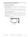
II.
SELECTING THE SITE ...............9-1
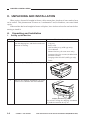
UNPACKING AND
INSTALLATION ............................9-2
A. Unpacking and Installation ....9-2
B. Placing Copy Paper............ 9-18
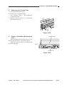
III. MOVING THE MACHINE .......... 9-21
CHAPTER 10 MAINTENANCE AND SERVICING
I.
II.
PERIODICALLY REPLACED
PARTS ....................................... 10-1
DURABLES AND
CONSUMABLES ...................... 10-1
COPYRIGHT © 1999 CANON INC.
III. SCHEDULED SERVICING ....... 10-1
CANON NP6512/6612/7120/7130/7130F REV.0 AUG. 1999 PRINTED IN JAPAN (IMPRIME AU JAPON)
vii
CHAPTER 11 TROUBLESHOOTING
I.
MAINTENANCE AND
INSPECTION ............................ 11-3
A. Image Adjustment Basic
Procedure ........................... 11-3
B. Points to Note for
Servicing ............................ 11-4
II. STANDARDS AND
ADJUSTMENTS ....................... 11-5
A. Mechanical ......................... 11-5
B. ADF .................................. 11-30
C. Electrical ........................... 11-41
III. TROUBLESHOOTING IMAGE
FAULTS ................................... 11-52
A. Making Initial Checks ....... 11-52
B. Sample Image Faults ....... 11-56
C. Troubleshooting Image
Faults ................................ 11-57
IV. TROUBLESHOOTING
MALFUNCTIONS .................... 11-65
A. Troubleshooting
Malfunctions ..................... 11-65
V. TROUBLESHOOTING FEEDING
PROBLEMS ............................ 11-77
A. Copy Paper Jam ............... 11-77
B. Faulty Feeding .................. 11-80
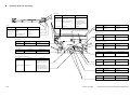
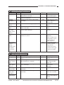
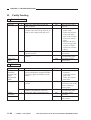
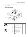
VI. ARRANGEMENT AND FUNCTIONS
OF ELECTRICAL PARTS ....... 11-81
A. Sensors and Solenoids .... 11-81
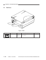
B. Switches ........................... 11-82
C. Lamp, Heater, Motor, Etc. 11-83
D. PCBs ................................ 11-84
E. ADF .................................. 11-85
F. Variable Resistors (VR) and
Check Pins by PCB .......... 11-86
VII. SERVICE MODE ..................... 11-88
A. Outline .............................. 11-88
B. Using Service Mode ......... 11-88
C. Adjustment Mode (30) ...... 11-91
D. Operation/Inspection
Mode (40) ......................... 11-92
E. Machine Settings
Mode (50) ......................... 11-93
F. Counter Mode (60) ........... 11-93
VIII. SELF DIAGNOSIS .................. 11-94
APPENDIX
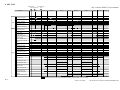
A. GENERAL TIMING CHART ........ A-1
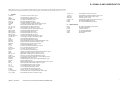
B. SIGNALS AND
ABBREVIATIONS ....................... A-3
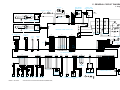
C. GENERAL CIRCUIT DIAGRAM . A-5
D. DC CONTROLLER CIRCUIT
DIAGRAM ................................... A-7
E. ADF CONTROLLER CIRCUIT
DIAGRAM ................................. A-15
F. COMPOSITE POWER SUPPLY
CIRCUIT DIAGRAM .................. A-19
G. CONTROL PANEL CIRCUIT
DIAGRAM ................................. A-29
H. AE SENSOR CIRCUIT
DIAGRAM ................................. A-31
viii
COPYRIGHT © 1999 CANON INC.
I.
J.
K.
L.
M.
N.
O.
P.
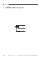
SENSOR CIRCUIT
DIAGRAM ................................. A-32
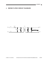
NOISE FILTER CIRCUIT
DIAGRAM ................................. A-33
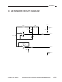
HIGH VOLTAGE CONTACT CIRCUIT
DIAGRAM ................................. A-34
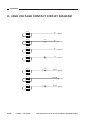
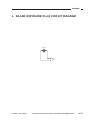
BLANK EXPOSURE (front) CIRCUIT
DIAGRAM ................................. A-35
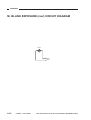
BLANK EXPOSURE (rear) CIRCUIT
DIAGRAM ................................. A-36
PRE-EXPOSURE CIRCUIT
DIAGRAM ................................. A-37
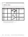
SPECIAL TOOLS ...................... A-38
SOLVENTS/OILS ...................... A-39
CANON NP6512/6612/7120/7130/7130F REV.0 AUG. 1999 PRINTED IN JAPAN (IMPRIME AU JAPON)
CHAPTER 1
GENERAL DESCRIPTION
This chapter provides specifications of the machine, instructions on how to operate
the machine, and an outline of copying process.
I.
II.
FEATURES ..................................1-1
SPECIFICATIONS .......................1-2
A. Copier ....................................1-2
B. ADF .......................................1-6
III. NAMES OF PARTS .....................1-8
A. External View ........................1-8
B. Cross Section ..................... 1-11
COPYRIGHT © 1999 CANON INC.
IV. USING THE MACHINE ............. 1-13
A. Control Panel...................... 1-13
B. User mode .......................... 1-15
V. ROUTINE MAINTENANCE BY THE
USER ........................................ 1-16
VI. IMAGE FORMATION ................ 1-19
A. Outline ................................ 1-19
CANON NP6512/6612/7120/7130/7130F REV.0 AUG. 1999 PRINTED IN JAPAN (IMPRIME AU JAPON)
CHAPTER 1 GENERAL DESCRIPTION
I.
FEATURES
1.
Personal Copier with a Zoom Function and a Fixed Copyboard
• You can choose either a default enlargement/reduction ratio or any ratio between 70% and
141% in 1% increments.
2.
Ecology-Conscious
• The use of a roller charging method has resulted in a considerable reduction of ozone: 0.01
ppm or less on the average, 0.02 ppm or less at maximum (1/100 to 1/1000 compared with
existing Canon machines).
3.
SURF Fixing Assembly
• The wait time is 0 sec (at 20°C room temperature), enabling speedy copying work immediately after power-on.
4.
Various Paper Sizes
• The paper may be between A4 (LGL) and A5 (STMT)(*Using the universal cassette).
• In manual feed mode, paper may be as large as A4 (LGL) or as small as a business card.
5.
Large Paper Source
• The source of paper may contain as many as 550 sheets of paper (500-sheet cassette type).
6.
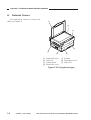
Separate top unit.
• The machine’s top unit may be opened to make jam removal easy.
7.
ADF Type
• Continuous copying is possible with the use of the ADF.
COPYRIGHT © 1999 CANON INC.
CANON NP6512/6612/7120/7130/7130F REV.0 AUG. 1999 PRINTED IN JAPAN (IMPRIME AU JAPON)
1-1
CHAPTER 1 GENERAL DESCRIPTION
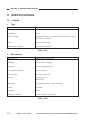
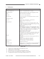
II. SPECIFICATIONS
A.
1.
Copier
Type
Item
Descriptions
Body
Desk top
Copyboard
Fixed
Source of light
Halogen lamp (80 V/110 W for 120V-model; 150 V/160 W
for 220/240 V-model)
Lens
Fixed focal point lens
Photosensitive medium
OPC drum (24-mm dia.)
Table 1-201
2.
Mechanisms
Reproduction
Descriptions
Indirect static reproduction
Charging
Roller (direct charging)
Exposure
Slit (moving light source)
Copy density adjustment
Auto or manual
Development
Dry (toner projection)
Pickup
Cassette (1 pc.)
Multifeeder
Separation
Curvature separation + static eliminator
Fixing
Flat heater
Cleaning
Blade
Original orientation
Center reference (copyboard)
Item
Table 1-202
1-2
COPYRIGHT © 1999 CANON INC.
CANON NP6512/6612/7120/7130/7130F REV.0 AUG. 1999 PRINTED IN JAPAN (IMPRIME AU JAPON)
CHAPTER 1 GENERAL DESCRIPTION
3.
Performance
Original type
Descriptions
Sheet, book, 3-D object (2kg max.)
Maximum original size
A4 (297 × 210 mm)/LGL (216 × 356 mm)
Reproduction ratio
Inch/AB-configuration: 2R2E Inch-configuration: 3R1E
Zoom
70% to 141% (in 1% increments)
Wait time
0 sec (at 20°C room temperature)
First copy time
10 sec or less (at 20°C room temperature; Direct, non-AE,
from the cassette)
Continuous copying
100 (max.)
Copy size
A4/LGL (297 × 210 mm/216 × 356 mm max.)
Business card (90 × 55 mm, min.)
Copy paper type
Cassette:
Plain paper (64 to 80 g/m2), tracing paper (SM-1, A4R/
B5R), colored paper, recycled paper (64 to 80 g/m2; A4R/
B5R), eco paper (80 g/m2; A4R)
Manual Feeder:
Plain paper (52 to 128 g/m2), tracing paper (SM-1, GNT80*1; A4R/B5R), transparency *1,*3 (A4R/LTRR*2), colored
paper, business card (200 g/m2 or less), label sheet*1 (A4R/
LTRR), recycled paper (64 to 80 g/m2; A4R/B5R), eco
paper (80 g/m2; A4R), postcard*2
Double-Sided/Overlay Copying*4:
Plain paper (64 to 128 g/m2), colored paper, business card
(200 g/m2 or less), recycled paper (64 to 80 g/m2; A4R/
B5R), eco paper (80 g/m2; A4R), postcard
Cassette
With claws
Universal cassette (250 sheets of 80 g/m2 paper; A4/LGL to
A5/STMT)
250-sheet cassette (250 sheets of 80 g/m2)
500-sheet cassette (500 sheets of 80 g/m2)
Multifeeder tray
5 mm deep (approx.; 50 sheets of 80 g/m2)
Copy tray
100 sheets (A4; 80 g/m2)
Non-image width
Leading edge: 2.0 ±1.5 mm (Direct; 4.0 mm or less otherwise)
Left/right: 0.0 +2.0, -0.0 mm (0 +4.0, -0.0 mm for LTR)
Auto power-off
Provided (5 min, approx.; fixed)*5
Item
Table 1-203
*1.
*2.
*3.
*4.
*5.
Applies only to single pickup if the multifeeder is used.
Applies only to vertical feeding.
Upon delivery, be sure to remove each from the copy tray.
Be sure to remove any curling before feeding for a second time.
If stopped because paper ran out during copying operation, 1 hr.
COPYRIGHT © 1999 CANON INC.
CANON NP6512/6612/7120/7130/7130F REV.0 AUG. 1999 PRINTED IN JAPAN (IMPRIME AU JAPON)
1-3
CHAPTER 1 GENERAL DESCRIPTION
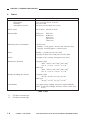
4.
Others
Descriptions
Item
Operating condition
Temperature
Humidity
Atmospheric pressure
7.5°C to 32.5°C/45.5°F to 90.5°F
5% to 85% RH
607.95 to 1013.25 hPa (0.6 to 1 atm)
Power source
120 V 60 Hz 220/240 V 50 Hz
Serial number
NVFxxxxx
NVHxxxxx
Maximum power consumption
0.9 kW or less
Standby: 1.2 W (approx.; about 5 min; reference only)
Copying: 0.4 kWh (approx.; reference only)
Noise
Standby: - (sound power level by ISO)
Copying: 66 dB or less (sound power level by ISO)
Ozone
0.01 ppm or less (average; 0.02 ppm or less, max.)
Dimensions (WxDxH)
Copyboard Type
484.9 × 448.2 × 297.5 mm*1/329.0 mm*2
19.1 in. × 17.6 in. × 11.7 in.*1/13.0 in.*2
ADF Type
484.9 × 448.2 × 358.3 mm*1/389.8 mm*2
19.1 in. × 17.6 in. × 14.1 in.*1/15.3 in.*2
Weight (including the cassette)
Copyboard Type
20.6 kg*1/45.3 lb*1, 22.5 kg*2/49.5 lb*2
ADF Type
24.4 kg*1/53.7 lb*1, 26.3 kg*2/57.9 lb*2
Consumables
Copy paper: Keep wrapped, and protect against humidity.
Toner: Avoid direct sunlight, and store at 40°C/104°F, 85%
or less.
PTZxxxxx
PUBxxxxx
PUCxxxxx
TWAxxxxx
TXAxxxxx
Table 1-204
*1.
*2.
1-4
250-sheet cassette type
500-sheet cassette type
COPYRIGHT © 1999 CANON INC.
CANON NP6512/6612/7120/7130/7130F REV.0 AUG. 1999 PRINTED IN JAPAN (IMPRIME AU JAPON)
CHAPTER 1 GENERAL DESCRIPTION
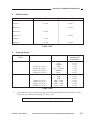
5.
Default Ratios
Item
Direct
2R2E (Inch/AB-configuration)
1:1.000
3R1E (Inch-configuration)
1:1.000
1:0.707
1:0.707
Reduce I
1:0.786
Reduce II
1:0816
Reduce III
1:0.860
Reduce IV
Enlarge I
1:1.154
Enlarge II
1:1.414
1:1.414
Table 1-205
6.
Copying Speed
Copying speed at
Direct
Reproduction ratio
Copy size
13
Direct
12
Reduce I (70.7%)
Reduce II (78.6%)
Reduce IV (86.0%)
Enlarge II (141.4%)
Direct
LTRR
LGL
STMTR
MIN
LGL → LTRR
MARJIN
MAX
A4R
B5R
A5R
A4R → A5R
B5R → A5R
B5R → A4R
A5R→ A4R
Reduce I (70.7%)
Reduce III (81.6%)
Enlarge I (115.4%)
Enlarge II (141.4%)
Number of copies
( Multifeeder*1)
(copies/min)
13 (9)
11 (8)
13 (9)
13 (9)
13 (9)
13 (9)
10 (9)
12 (9)
12 (9)
12 (9)
12 (9)
12 (9)
12 (9)
10 (9)
Table 1-206
*1.
The number of copies starting with the pickup operation that follows the delivery of the
19th copy in a continuous copying job. (See p.5-5)
The specifications are subject to change for product improvement.
COPYRIGHT © 1999 CANON INC.
CANON NP6512/6612/7120/7130/7130F REV.0 AUG. 1999 PRINTED IN JAPAN (IMPRIME AU JAPON)
1-5
CHAPTER 1 GENERAL DESCRIPTION
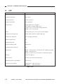
B.
ADF
Descriptions
Item
Original pickup
Auto pickup/delivery
Original orientation
Face-down
Original position
Center reference
Original separation
Top separation
Original type
Single-sided (50 to 128 g/m2)
A5 (STMT) to A4R (LTRR), LGL
Length: 139.7 to 355.6 mm (feeding direction)
Width: 139.7 to 215.9 mm
Stack
30 sheets (80 g/m2 or less; about 3 mm in height)
Original processing mode
Single-sided original to single-sided copy
Original size detection
Yes (in feeding direction)
Mixed original sizes
No
Original detection
Yes
Original feeding speed
446 mm/sec
Communication with host
IPC
Dimensions
Width: 474 mm/18.7 in. (659 mm/25.9 in. with the tray open)
Depth: 394 mm/15.5in.
Height: 74 mm/2.9 in. (216 mm/8.5 in. with the tray open)
Weight
5 kg/11 lb (approx.)
Power source
24 VDC and 5 VDC (from the host)
Maximum power consumption
40 W or less
Operating environment
Temperature: same as the host
Humidity:
same as the host
Table 1-207
1-6
COPYRIGHT © 1999 CANON INC.
CANON NP6512/6612/7120/7130/7130F REV.0 AUG. 1999 PRINTED IN JAPAN (IMPRIME AU JAPON)
CHAPTER 1 GENERAL DESCRIPTION
*1.
The following may not be used as an original:
• Sheet with a staple, clip, or glue.
• Sheet with a cut, hole, or tear.
• Sheet with holes for binding.
• Sheet with a carbon back.
• Sheet with a cut-and-paste piece.
• Sheet with curling, bending, or wrinkling.
The specifications are subject to change for product improvement.
COPYRIGHT © 1999 CANON INC.
CANON NP6512/6612/7120/7130/7130F REV.0 AUG. 1999 PRINTED IN JAPAN (IMPRIME AU JAPON)
1-7
CHAPTER 1 GENERAL DESCRIPTION
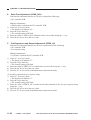
III. NAMES OF PARTS
A.
1.
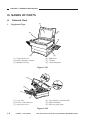
External View
[1]
Copyboard Type
[2]
[6]
[3]
[4]
[5]
[1] Copyboard cover
[2] Static eliminator cleaner
[3] Manual feed tray
[4] Right door
[5] Cassette
[6] Copyboard glass
Figure 1-301
[4]
[3]
[5]
[2]
[1]
[6]
[1] Copy tray
[2] Power cord connector
[3] Open/close lever
[4] Copy density correction dial
[5] Static eliminator
[6] Delivery guide plate
Figure 1-302
1-8
COPYRIGHT © 1999 CANON INC.
CANON NP6512/6612/7120/7130/7130F REV.0 AUG. 1999 PRINTED IN JAPAN (IMPRIME AU JAPON)
CHAPTER 1 GENERAL DESCRIPTION
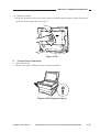
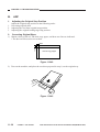
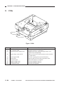
2.
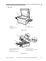
ADF Type
[1]
[5]
[2]
[3]
[4]
[4] Cassette
[5] Copyboard glass
[1] ADF
[2] Manual feed tray
[3] Right door
Figure 1-303
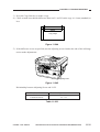
[6]
[5]
[7]
[4]
[3]
[2]
[1]
[1]
[2]
[3]
[4]
Static eliminator cleaner
Delivery guide plate
Copy tray
Power cord connector
[5] Open/close lever
[6] Copy density correction dial
[7] Static eliminator
Figure 1-304
COPYRIGHT © 1999 CANON INC.
CANON NP6512/6612/7120/7130/7130F REV.0 AUG. 1999 PRINTED IN JAPAN (IMPRIME AU JAPON)
1-9
CHAPTER 1 GENERAL DESCRIPTION
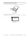
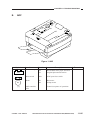
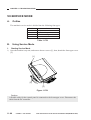
3.
ADF
[3]
[4]
[2]
[1]
[1] Original tray
[2] Original delivery tray
[3] Slide guide
[4] Auxiliary tray
Figure 1-305
1-10
COPYRIGHT © 1999 CANON INC.
CANON NP6512/6612/7120/7130/7130F REV.0 AUG. 1999 PRINTED IN JAPAN (IMPRIME AU JAPON)
CHAPTER 1 GENERAL DESCRIPTION
B.
1.
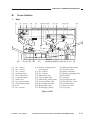
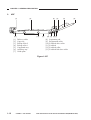
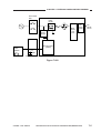
Cross Section
Body
[1]
[2]
[32]
[1]
[2]
[3]
[4]
[5]
[6]
[7]
[8]
[9]
[10]
[11]
[3] [4]
[5]
[31] [30] [29]
No. 3 mirror
No. 2 mirror
No. 1 mirror
Scanning lamp
Heat exhaust fan
Copyboard glass
Drum Unit
Pre-exposure lamp
Side blanking lamp
Lens
No. 6 mirror
[6]
[28]
[7] [8] [9] [10]
[27]
[11] [12]
[13] [14]
[26] [25][24] [23] [22] [21] [20] [19] [18] [17]
[12] Primary charging roller
cleaning pad
[13] No. 4 mirror
[14] No. 5 mirror
[15] Multifeeder tray
[16] Vertical path roller
[17] Multifeeder pickup roller
[18] Cassette pickup roller
[19] Developing assembly
[20] Registration roller
[21] Developing cylinder
[22]
[23]
[24]
[25]
[26]
[27]
[28]
[29]
[30]
[31]
[32]
[15]
[16]
Photosensitive drum
Transfer roller
Static eliminator
Primary charging roller
Feed belt
Cassette
Fixing upper unit
Fixing lower roller
Cleaning roller
Delivery roller
Copy tray
Figure 1-306
COPYRIGHT © 1999 CANON INC.
CANON NP6512/6612/7120/7130/7130F REV.0 AUG. 1999 PRINTED IN JAPAN (IMPRIME AU JAPON)
1-11
CHAPTER 1 GENERAL DESCRIPTION
2.
ADF
[1]
[2]
[13]
[1]
[2]
[3]
[4]
[5]
[6]
[7]
[3]
[12]
Delivery roller
Copy tray
Pickup roller 2
Pickup roller 1
Copyboard tray
Auxiliary tray
Guide plate
[11]
[10] [9]
[8]
[9]
[10]
[11]
[12]
[13]
[4]
[5]
[6]
[8] [7]
Separation pad
Registration roller
Feed belt drive roller
Feed belt
Feed belt roller
Feed belt link slave roller
Figure 1-307
1-12
COPYRIGHT © 1999 CANON INC.
CANON NP6512/6612/7120/7130/7130F REV.0 AUG. 1999 PRINTED IN JAPAN (IMPRIME AU JAPON)
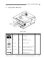
CHAPTER 1 GENERAL DESCRIPTION
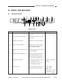
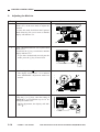
IV. USING THE MACHINE
A.
Control Panel
[1]
[2]
[17]
[3]
[16]
[4] [5] [6] [7]
[8]
[15] [14] [13][12]
[11]
[9]
[10]
Figure 1-401
No.
1
Name
Copy density adjusting lever
Description
Adjusts the density of copies
manually.
2
Copy density mode indicator
Indicates the selected copy density mode.
3
Default ratio indicator
Indicates the selected default ratio.
4
Paper selection indicator
Indicates the selected cassette/
manual feed tray. If there is no
paper loaded, it flashes.
5
Replace toner cartridge indicator
Flashes when the toner cartridge
must be replaced
6
Replace drum unit indicator
Flashes to indicate that the drum
unit must be replaced. If also
flashes when it is necessary to
have waste toner disposed of.
7
Count/ratio indicator
• Indicates the number of copies
or reproduction ratio.
• The symbol “%” turns on
when indicating a ratio.
100 (max.; continuous
copying)
8
Clear/stop key
Stops copying or returns copying mode to standard mode.
Standard Mode
Ratio: 100%
Count: 1
Paper source: cassette
Copy density: auto
mode
COPYRIGHT © 1999 CANON INC.
Remarks
CANON NP6512/6612/7120/7130/7130F REV.0 AUG. 1999 PRINTED IN JAPAN (IMPRIME AU JAPON)
1-13
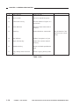
CHAPTER 1 GENERAL DESCRIPTION
No.
9
Name
Copy start key
Description
Starts copying.
10
Power switch
Turns on and off the power.
11
Count/zoom set key
Sets the number of copies or a
zoom ratio.
12
Zoom indicator
Turns on when zoom mode is
selected.
13
Zoom key
Selects/deselects zoom mode.
14
Jam indicator
Flashes in response to a jam.
15
Paper selection key
Selects the cassette/ manual
feed tray.
16
Default ratio key
Selects a default reproduction
ratio.
17
Copy density mode selection
key
Selects copying density mode.
Remarks
May be between 70%
and 141% in 1% increments.
Table 1-401
1-14
COPYRIGHT © 1999 CANON INC.
CANON NP6512/6612/7120/7130/7130F REV.0 AUG. 1999 PRINTED IN JAPAN (IMPRIME AU JAPON)
CHAPTER 1 GENERAL DESCRIPTION
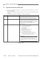
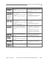
B.
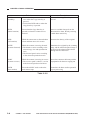
User mode
Indication
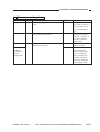
U1
Function
Primary charging roller cleaning
Description
Use it to clean the primary charging roller.
(See p. 4-31.)
U5*
DF recovery mode on/off
Use it to enable/disable recovery mode with the
DF in use:
00: disable.
01: enable.
U6*
Feeder cleaning
Use it to clean the feeder. (See p. 1-16.)
U7
Installation/drum replacement mode
Use it at time of installation or replacement of
the drum unit. (See p. 9-14.)
• Indications
‘71’: Enter ‘PRIMARY’.
‘72’: Enter ‘IP_OFST’.
‘73’: Enter the drum counter reading (in units of
1000 sheets).
If no input is entered, ‘0’ will be assumed.
‘74’: Measures APVC and stirs toner.
U9
Reserved.
-------------------------------
*Only if an ADF is installed.
Table 1-402
COPYRIGHT © 1999 CANON INC.
CANON NP6512/6612/7120/7130/7130F REV.0 AUG. 1999 PRINTED IN JAPAN (IMPRIME AU JAPON)
1-15
CHAPTER 1 GENERAL DESCRIPTION
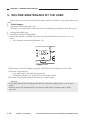
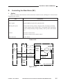
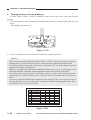
V. ROUTINE MAINTENANCE BY THE USER
Instruct the user to clean the following if images tend to be soiled or copy paper tends to jam
often.
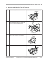
1. Soiled Images
a. Copyboard Glass/Copyboard Cover
Clean the cover with a moist cloth (with water or mild detergent solution); then, dry wipe it.
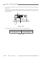
b. Feeding Belt (ADF type)
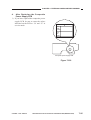
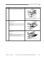
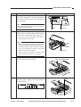
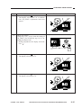
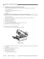
b.1 Cleaning in Feeder Cleaning Mode
1) Turn on the machine, and hold down the Copy Density Mode Selection key for 4 sec or
more.
• The count/ratio indicator will indicate ‘U6’.
Zoom
Figure 1-501
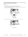
2) Place about 10 sheets of blank copy paper (A4/LTR) on the original tray of the ADF.
3) Press the Copy Start key.
• Copy paper will be fed from the original tray.
• The indicator flashes ‘U6’ while the feeder is being cleaned.
4) Press the Copy Density Mode Selection key to end the mode.
Caution:
• You cannot start feeder cleaning mode while the machine is making copies or if an error
exists.
• The auto power-off mechanism does not operate while feeder cleaning mode is being
executed.
1-16
COPYRIGHT © 1999 CANON INC.
CANON NP6512/6612/7120/7130/7130F REV.0 AUG. 1999 PRINTED IN JAPAN (IMPRIME AU JAPON)
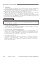
CHAPTER 1 GENERAL DESCRIPTION
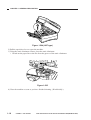
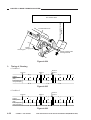
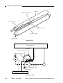
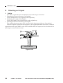
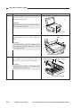
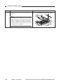
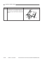
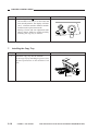
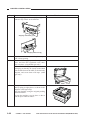
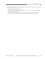
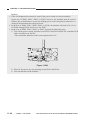
b.2 Cleaning by Hand
1) Wipe the feed belt with a moist cloth (water or mild detergent solution) in the direction of
the arrow in the figure; then, dry wipe it.
Figure 1-502
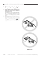
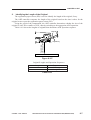
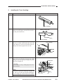
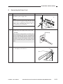
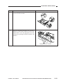
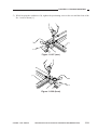
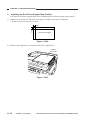
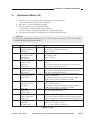
2. If Jams Occur Frequently
a. Static Eliminator
1) Remove the static eliminator cleaner from the machine.
Figure 1-503 (Copyboard type)
COPYRIGHT © 1999 CANON INC.
CANON NP6512/6612/7120/7130/7130F REV.0 AUG. 1999 PRINTED IN JAPAN (IMPRIME AU JAPON)
1-17
CHAPTER 1 GENERAL DESCRIPTION
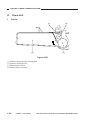
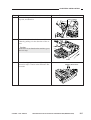
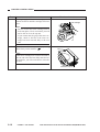
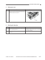
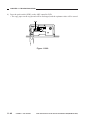
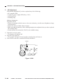
Figure 1-504 (ADF type)
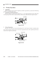
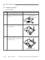
2) Pull the open/close lever to open the machine.
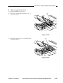
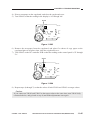
3) Using the static eliminator cleaner, clean the static eliminator.
• Brush out the paper lint or the like from the groove of the static eliminator.
Figure 1-505
4) Close the machine as soon as you have finished cleaning. (Work briskly.)
1-18
COPYRIGHT © 1999 CANON INC.
CANON NP6512/6612/7120/7130/7130F REV.0 AUG. 1999 PRINTED IN JAPAN (IMPRIME AU JAPON)
CHAPTER 1 GENERAL DESCRIPTION
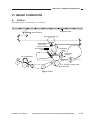
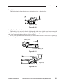
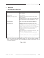
VI. IMAGE FORMATION
A.
Outline
The construction of the machine is as follows:
Copyboard glass
Scanning lamp
Fixed focal point lens
Side blanking lamp
(front, rear)
Primary charging roller
Pre-exposure
lamp
Developing
blade
Photosensitive drum
Fixing assembly
Developing
cylinder
Cleaning blade
Transfer charging roller
Static eliminator
Figure 1-601
COPYRIGHT © 1999 CANON INC.
CANON NP6512/6612/7120/7130/7130F REV.0 AUG. 1999 PRINTED IN JAPAN (IMPRIME AU JAPON)
1-19
CHAPTER 1 GENERAL DESCRIPTION
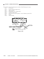
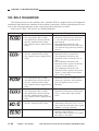
The machine’s image formation process consists of the following seven steps:
Step 1
Pre-exposure
Step 2
Primary charging (negative DC)
Step 3
Image exposure
Step 4
Development (AC + negative DC)
Step 5
Transfer (negative DC)
Step 6
Separation (curvature separation + static eliminator; positive DC)
Step 7
Fixing
Step 8
Drum cleaning
Static latent image formation block
2. Primary charging
3. Image exposure
1. Pre-exposure
8. Drum cleaning
4. Development
Manual feed
5. Transfer
Delivery
7. Fixing
6. Separation
Registration
Cassette
: Flow of copy paper
: Rotation of the photosensitive drum
Figure 1-602
1-20
COPYRIGHT © 1999 CANON INC.
CANON NP6512/6612/7120/7130/7130F REV.0 AUG. 1999 PRINTED IN JAPAN (IMPRIME AU JAPON)
CHAPTER 2
BASIC OPERATION
This chapter provides descriptions on basic operations, functions of each operation,
relationships between electrical and mechanical systems, and timing at which each
associated part is turned on.
Process speed
I.
BASIC OPERATIONS ..................2-1
A. Functional Construction ........2-1
B. Outline of Electrical
Circuitry .................................2-2
C. Basic Sequence of
Operations .............................2-3
COPYRIGHT © 1999 CANON INC.
96 mm/sec
D. Controlling the Main
Motor (M1) .............................2-5
E. Inputs to and Outputs from the
DC Controller ........................2-7
CANON NP6512/6612/7120/7130/7130F REV.0 AUG. 1999 PRINTED IN JAPAN (IMPRIME AU JAPON)
CHAPTER 2 BASIC OPERATION
I. BASIC OPERATIONS
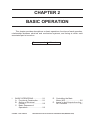
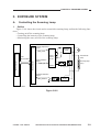
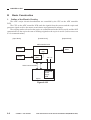
A.
Functional Construction
The machine consists of four functional blocks: pickup/feeding system, exposure system, image formation system, and control system.
Control system
Exposure system
Control panel
Copyboard
Original
illuminating block
Control circuit
Optical block
Image formation
system
Primary charging
roller
Drum
cleaning block
Photosensitive
drum
Transfer/
separation
Feeding
Developing
assembly
ck
d blo
Pickup
control block
ee
ual f
Man
Copy tray
Fixing assembly/
delivery assembly
Cassette
Pickup/
feeding system
Figure 2-101
COPYRIGHT © 1999 CANON INC.
CANON NP6512/6612/7120/7130/7130F REV.0 AUG. 1999 PRINTED IN JAPAN (IMPRIME AU JAPON)
2-1
CHAPTER 2 BASIC OPERATION
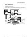
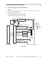
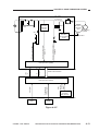
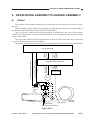
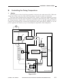
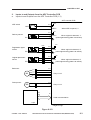
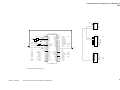
B.
Outline of Electrical Circuitry
The machine's major electric mechanisms are controlled by the microprocessor mounted on
the DC controller PCB, which reads input signals from sensors and operating keys according to the
instructions of the program stored in advance and sends signals used to drive motors, solenoids,
lamps, and other loads as needed.
<Sensor Block>
Sensor
<Control Block>
DC controller PCB
• Scanner home position detection
• Lens home position detection
• Pre-registration roller paper
detection
• Delivery paper detection
• Vertical path roller paper detection
• Waste toner detection
Q101
CPU
+5V
+24V
<Loads>
Composite
power supply PCB
Scanning lamp
Q900
CPU
Fixing heater
Highvoltage
circuit
block
Contact
PCB
• Primary charging roller
• Developing cylinder
• Transfer charging roller
• Static eliminator
AE sensor
PCB
Toner level
detection PCB
Thermistor
• Scanner thermistor
• Fixing thermistor
Solenoid
Control
panel
Main motor
driver PCB
Main
motor
• Pickup clutch solenoid
• Registration clutch solenoid
• Lens drive solenoid
• Multifeeder pickup solenoid
• Cassette pickup solenoid
• Primary charging roller cleaning solenoid
Side blanking
lamp
Scanner/
lens drive motor
Pre-exposure
lamp
Power
switch
Scanner cooling fan
Counter
Sensor/
switch
ADF
ADF load
Figure 2-102
2-2
COPYRIGHT © 1999 CANON INC.
CANON NP6512/6612/7120/7130/7130F REV.0 AUG. 1999 PRINTED IN JAPAN (IMPRIME AU JAPON)
CHAPTER 2 BASIC OPERATION
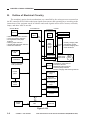
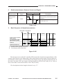
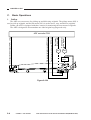
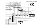
C.
Basic Sequence of Operations
• A4R, Direct, 2 Copies, Continuous, Cassette
Power switch
ON
Copy Start key
ON
STBY INTR AER
Main motor (M1)
Scanner lamp (LA1)
Scanner
Pre-exposure lamp
Primary bias
Developing AC bias
Developing DC bias
Transfer bias
Static eliminator bias
SCFW
SCRV
SCFW
SCRV LSTR STBY
0.3sec (approx.)
I II
I
Forward
Reverse
Heater (H1)
I: Scanner home position detection
II: Lens home position detection
Figure 2-103
COPYRIGHT © 1999 CANON INC.
CANON NP6512/6612/7120/7130/7130F REV.0 AUG. 1999 PRINTED IN JAPAN (IMPRIME AU JAPON)
2-3
CHAPTER 2 BASIC OPERATION
Period
• From when he power switch is turned
on to when the Copy Start key is
pressed.
• From when LSTR ends to when the
Copy Start key is pressed.
Description
Waits until the Copy Start key is
pressed.
INTR
(initial rotation)
From when the Copy Start key is
pressed to when the scanner moves
forward.
Removes residual charges from the
photosensitive drum, thereby ensuring
a stable drum sensitivity.
AER
(AE rotation)
While the scanner moves forward about
10 cm and then moves it in reverse.
Measures the density of the original.
SCFW
(scanner forward)
While the scanner is moving forward.
• The distance varies according to the
selected copy size and reproduction
ratio.
• The forward speed varies according
to the selected reproduction ratio.
Illuminates the original by the scanning
lamp, and the reflected optical image is
projected to the photosensitive drum
through mirrors and lenses.
SCRV
(scanner reverse)
While the scanner is moving in reverse.
• The reverse speed is about 3.3 as fast
as the forward speed used in Direct.
Moves the scanner to the home position
in preparation for the next copying run.
LSTR
(last rotation)
From when SCRV ends to when the
main motor stops.
Neutralizes the drum surface potential
as post-processing.
STBY
(standby)
Table 2-101
2-4
COPYRIGHT © 1999 CANON INC.
CANON NP6512/6612/7120/7130/7130F REV.0 AUG. 1999 PRINTED IN JAPAN (IMPRIME AU JAPON)
CHAPTER 2 BASIC OPERATION
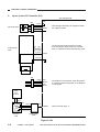
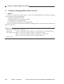
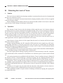
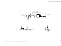
D.
Controlling the Main Motor (M1)
1.
Outline
Table 2-102 shows the functions of the main motor control circuit, and Figure 2-104 is a block
diagram of the circuit.
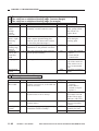
Item
Power supply
Description
24 VDC from the composite power supply.
Drive signal
Signal (MMD) from the DC controller PCB.
Moving/drive parts
Photosensitive drum, primary charging roller, developing assembly,
transfer charging roller, pickup roller, vertical path roller, registration
roller, feeding assembly, fixing assembly, delivery roller, heat exhaust
fan
Control
Executes on/off control.
Executes constant speed rotation control.
Error detection
Issues ‘E010’.
Table 2-102
+24V
J205
-4
24V
-3
GND
-2
J103 J203
-3
-7
-2
MMD
-3
J104 J204
-1
-7
-1
DC
controller
PCB
J901
-1
Clock pulse
generator
Phase
control
drive
circuit
Drive
current
Main motor
(M1)
Hall IC output
MLOCK -4
MMCLK
Composite
power
supply
PCB
Reference signal
Main motor drive PCB
Figure 2-104
COPYRIGHT © 1999 CANON INC.
CANON NP6512/6612/7120/7130/7130F REV.0 AUG. 1999 PRINTED IN JAPAN (IMPRIME AU JAPON)
2-5
CHAPTER 2 BASIC OPERATION
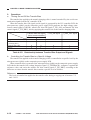
2.
Operations
The main motor (M1) is a DC motor with a built-in clock pulse generator, which generates
clock pulses (MMCLK) in relation to the rotation of the motor while the motor is rotating.
The speed control circuit controls the main motor (M1) so that it rotates at a specific speed by
matching the frequency of these clock pulses and that of the reference signals.
When the main motor drive signal (MMD) from the DC controller circuit goes ‘1’, the motor
diver drive circuit turns on, causing the main motor (M1) to rotate at a specific speed.
While the main motor is rotating at a specific speed, the main motor driver PCB keeps sending
the constant speed state signal (MLOCK=0) to the DC controller PCB. If the rotation of the motor
starts to have fluctuations, the MLOCK signal goes ‘1’.
Related Error Code
E010
While the main motor drive signal is generated, the rotation of the main motor deviates from
a specific number for 1 sec or more.
a.
Turning On/Off the Main Motor
When the main motor drive signal (MMD) from the DC controller circuit goes ‘1’, the main
motor driver turns on to rotate the main motor (M1).
b.
Rotating the Main Motor at a Constant Speed
The drive circuit on the motor driver PCB controls the main motor so that the phase of the
frequency of the clock pulse signals (MMCLK) occurring when the motor rotates and that of
the frequency of the reference signals match. The main motor driver PCB sends the constant
speed state signal (MLOCK=0) to the DC controller circuit.
c.
Detecting an Error (E010)
If the rotation of the main motor starts to have fluctuations for some reason, the MLOCK
signal goes ‘1’. If the signal remains ‘1’ for about 1 sec, the DC controller will find the
condition to be a fault in the main motor, and will stop the main motor and, at the same time,
indicate ‘E010’ in the display.
2-6
COPYRIGHT © 1999 CANON INC.
CANON NP6512/6612/7120/7130/7130F REV.0 AUG. 1999 PRINTED IN JAPAN (IMPRIME AU JAPON)
CHAPTER 2 BASIC OPERATION
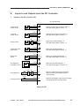
E.
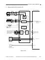
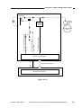
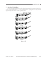
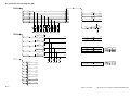
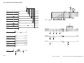
1.
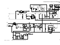
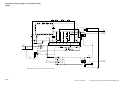
Inputs to and Outputs from the DC Controller
Inputs to the DC Control (1/2)
DC controller PCB
Scanner home
position sensor
+5V
J101-1
-3 SCHP
-2
PS1
Lens home
position sensor
PS2
+5V
J109-11
-10 LHP
-9
PS3
J62 J102-7
DIG3
-9 DPD
-8
When PS3 has detected paper, ‘0’.
(The light-blocking plate is at PS3, ‘1’.)
PS4
+5V
J132-3
-5
PDP
-4
When PS4 has detected paper, ‘1’.
(The light-blocking plate is at PS4, ‘1’.)
PS5
J121-4
DIG1
-3
TNFULL
-5
When toner reaches specific level, ‘1’.
(The light-blocking plate is at PS5, ‘0’.)
Delivery sensor
Vertical path roller
paper sensor
Waste toner
sensor
When the scanner is in the home position, ‘1’.
(The light-blocking plate is at PS1, ‘1’.)
When the lens is in the home position, ‘1’.
(The light-blocking plate is at PS2, ‘1’.)
+5V
Pre-registration
roller paper sensor
J108-2
-1
RPD
-3
Q751
When Q751 has detected paper, ‘1’.
(The light-blocking plate is at PS751, ‘0’.)
Sensor PCB
TH1 J433 J62 J102-1
Fixing thermistor
TH1
When the surface temperature of the fixing
heater increases, the voltage decreases.
(analog signal)
TH2
When the temperature of the scanner increases,
the voltage decreases. (analog signal)
-6
TH2
Scanner thermistor
J131-1
-2
Figure 2-105
COPYRIGHT © 1999 CANON INC.
CANON NP6512/6612/7120/7130/7130F REV.0 AUG. 1999 PRINTED IN JAPAN (IMPRIME AU JAPON)
2-7
CHAPTER 2 BASIC OPERATION
2.
Inputs to the DC Controller (2/2)
DC controller PCB
J601
+24V
AE sensor PCB
+24V
J107-4
-3
AE
-2 AEREF
-1
The keys and the LEDs are wired in a matrix
in the control panel PCB, and the DC controller
turns on or flashes the LEDs and reads key inputs.
J301 J111
Control panel
PCB
J111-15
When the light reflected by the original increases,
the voltage increases.
PWOFF
J111-16
SW309
Power switch
J62
J102-2
-3
-4
-5
DIG1
HEAT0
DIG1
HEAT1
The variation in the resistance of the fixing heater
is corrected in three levels based on combinations
of 2-bit signals.
TNMONI
when toner level drops, ‘0’.
Toner
level
antenna
-2
J951-1
J954
+24V -3
-2
-1
J952
Toner level
detection
PCB
J214-1
-2
-3
J215
J103
-1
Composite
power supply
PCB
Figure 2-106
2-8
COPYRIGHT © 1999 CANON INC.
CANON NP6512/6612/7120/7130/7130F REV.0 AUG. 1999 PRINTED IN JAPAN (IMPRIME AU JAPON)
CHAPTER 2 BASIC OPERATION
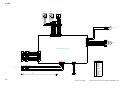
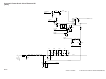
3.
Outputs from the DC Controller (1/2)
Composite power supply PCB
Line filter
J201-2
LF1
(220/240V model only) NF1
DS1
-1
Noise filter
Door switch
Fixing heater J16
J434
H1
FU2
Transformer
J207-1
-2
Fixing heater
activation circuit
Thermal
fuse 2
Scanning lamp
FU1
DC controller PCB
LA1
J104-2
HEAT_TRG When ‘0’,
the fixing heater
turns on.
J910-3
-1
Scanning lamp
activation circuit
Thermal fuse 1
Primary charging roller
Developing cylinder
Transfer charging roller
Static eliminator
Highvoltage
circuit
block
Microprocessor
Communication with
the composite power
supply
HVT board
+24V
J103-7
MMD
J104-1
MLOCK
M1
Main
motor
See p. 2-5.
Main motor
driver PCB
See p. 3-7.
M2
Scanner/
lens drive motor
Figure 2-107
COPYRIGHT © 1999 CANON INC.
CANON NP6512/6612/7120/7130/7130F REV.0 AUG. 1999 PRINTED IN JAPAN (IMPRIME AU JAPON)
2-9
CHAPTER 2 BASIC OPERATION
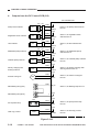
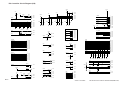
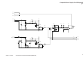
4.
Outputs from the DC Control PCB (2/2)
DC controller PCB
J53 J51
Pickup clutch solenoid
SL1
-3
SL2
-5
SL3
SL4
Cassette pickup solenoid
SL5
When ‘0’, the registration clutch
solenoid turns on.
+24V
LNSLD*
When ‘0’, the lens solenoid turns
on.
+24V
J109-8
-7
J58
RGSLD*
J109-2
-1
J55 J51
Multifeeder pickup solenoid
When ‘0’, the pickup clutch solenoid
turns on.
J109-6
J52
Lens solenoid
PUSLD*
+24V
J54
Registration clutch solenoid
+24V
J109-4
MFSLD*
When ‘0’, the multifeeder pickup
solenoid turns on.
+24V
J132-2
-1
CPUSD*
When ‘0’, the cassette pickup solenoid
turns on.
+24V
J122-2
Primary charging roller
cleaning solenoid
SL6
-1
PCSLD*
When ‘0’, the primary charging roller
cleaning solenoid turns on.
+24V
J130-1
Scanner cooling fan
FM1
-2
J106-1
FM1D*
When ‘0’, the scanner cooling fan
turns on.
SB_LP*
Side blanking lamp (rear)
When ‘0’, the blanking lamp turns on.
+24V
Side blanking lamp (front)
-2
LA2
Pre-exposure lamp
+24V
J121-2
-1
PEXP*
When ‘0’, the pre-exposure lamp
turns on.
+24V
J119-2
Total copy counter
CNT1
-1
TCNTD*
When ‘0’, the total copy counter
turns on.
Figure 2-108
2-10
COPYRIGHT © 1999 CANON INC.
CANON NP6512/6612/7120/7130/7130F REV.0 AUG. 1999 PRINTED IN JAPAN (IMPRIME AU JAPON)
CHAPTER 2 BASIC OPERATION
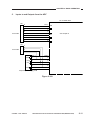
5.
Inputs to and Outputs from the ADF
DC controller PCB
J60
To the ADF
J24
To the ADF
-8
J114-1
-7
-2
-6
-3
-5
-4
-4
-5
-3
-6
-2
-7
-1
-8
REQ
ACK
TXD
See Chapter 8.
RXD
-4
-3
-2
-1
J202-1
J105-6
+24V
-2
-5
+5V
-3
-4
+5V
-4
-3
-5
-2
-6
-1
+24V
Composite power supply PCB
Figure 2-109
COPYRIGHT © 1999 CANON INC.
CANON NP6512/6612/7120/7130/7130F REV.0 AUG. 1999 PRINTED IN JAPAN (IMPRIME AU JAPON)
2-11
CHAPTER 3
EXPOSURE SYSTEM
This chapter discusses the principles of operation used for the machine's lens drive
unit and scanner drive unit. It also explains the timing at which these drive units are
operated, and shows how they may be disassembled/assmbled and adjusted.
I.
II.
OPERATIONS ..............................3-1
A. Outline ...................................3-1
B. Varying the Reproduction
Ratio ......................................3-2
C. Lens Drive System ................3-3
D. Scanner Drive System ..........3-4
EXPOSURE SYSTEM .................3-9
A. Controlling the Scanning
Lamp .....................................3-9
COPYRIGHT © 1999 CANON INC.
III. DISASSEMBLY/ASSEMBLY .....
A. Scanner Drive Assembly ....
B. Lens Drive Assembly .........
C. Exposure System ...............
CANON NP6512/6612/7120/7130/7130F REV.0 AUG. 1999 PRINTED IN JAPAN (IMPRIME AU JAPON)
3-13
3-14
3-32
3-38
CHAPTER 3 EXPOSURE SYSTEM
I.
OPERATIONS
A.
Outline
Table 3-101 shows the major functions of the exposure system.
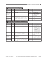
Item
Description
Lamp
Halogen
Scanning
By moving the No. 1 mirror mount
Scanner position detection
By a sensor (scanner home position sensor; PS1)
Ratio variation
Main scanning direction:by varying the optical length
Sub scanning direction:by varying the speed of the No. 1 mirror mount
Lens drive control
Scanner/lens drive motor (M2)
Fixed focal point lens unit
Mobile No. 4/5 mirror unit
Scanner drive control
Scanner/lens drive motor (M2)
Scanner thermistor (TH2)
Protective function
By a fuse (blows in response to overheating of the scanning lamp to cut
power to the lamp)
• Thermal fuse (FU1; blows at 128°C)
Table 3-101
Copyboard glass
Enlarge Reduce
Moves for enlargement/
reduction
Fixed focal point lens
No. 4/5 mirror unit
Photosensitive
drum
Figure 3-101
COPYRIGHT © 1999 CANON INC.
CANON NP6512/6612/7120/7130/7130F REV.0 AUG. 1999 PRINTED IN JAPAN (IMPRIME AU JAPON)
3-1
CHAPTER 3 EXPOSURE SYSTEM
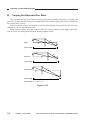
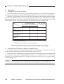
B.
Varying the Reproduction Ratio
The reproduction ratio in the drum axial direction (main scanning direction) is varied by the
lens drive system, and that in the drum peripheral direction (sub scanning direction) is changed by
the scanner drive system.
In the lens drive system, the positions of the fixed focal point lens and the No. 4/5 mirror are
changed to vary the reproduction ratio.
In the scanner system, the relative speed of the No. 1 mirror mount is made higher (for reduction) or lower (for enlargement) than the drum peripheral speed.
F'
Direct
F
Optical length
L1
F'
Reduction
F
Optical length
L2
F'
Enlargement
F
Optical length
L3
Optical length: L1 < L2, L1 < L3
Figure 3-102
3-2
COPYRIGHT © 1999 CANON INC.
CANON NP6512/6612/7120/7130/7130F REV.0 AUG. 1999 PRINTED IN JAPAN (IMPRIME AU JAPON)
CHAPTER 3 EXPOSURE SYSTEM
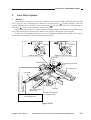
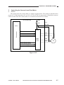
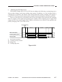
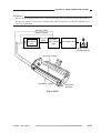
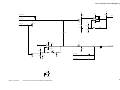
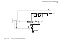
C.
Lens Drive System
1.
Outline
The lens drive system is driven by the scanner/lens drive motor (M2). When the lens solenoid
(SL3) turns on, the switching gear is pushed in the direction of . In this condition, when the
scanner/lens drive motor rotates in reverse direction ( ), the lens unit will move in the direction of
reduction ( ) by the work of the gear and the lens cable.
At the same time, the No. 4/5 mirror unit operates according to the distance over which the lens
unit is moved by the work of the gear and the cam, thereby varying the optical length.
At this time, the blanking lamp also moves in conjunction with the lens to blank out the appropriate front/rear widths to suit the selected reduction ratio.
SL3
ON
SL3
OFF
Switching
gear
Switching
gear
While the scanner is moving
Top View
While the lens is moving
Cam
Switching gear
Scanner/lens drive motor
(M2)
SL3
Lens cable
Lens home position detection
signal(LHP)
Lens solenoid drive signal(LNSLD*)
No. 4/5 mirror unit
Reduction
Enlargement
Lens home position
sensor (PS2)
Lens unit
Lens shift detecting shaft
for side blanking lamp
DC controller PCB
Figure 3-103
COPYRIGHT © 1999 CANON INC.
CANON NP6512/6612/7120/7130/7130F REV.0 AUG. 1999 PRINTED IN JAPAN (IMPRIME AU JAPON)
3-3
CHAPTER 3 EXPOSURE SYSTEM
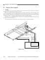
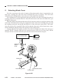
D.
Scanner Drive System
1.
Outline
The scanner is driven by the scanner/lens drive motor (M2), whose direction of rotation
changes to move the scanner forward or in reverse.
When moving the scanner forward, the speed of rotation of the motor varies according to the
selected reproduction ratio on a continuous basis; when moving the scanner in reverse, on the other
hand, its speed remains the same regardless of the selected reproduction ratio in normal copying
(312mm/sec, about 3.3 as fast as when moving the scanner forward in Direct).
The distance over which the scanner is moved varies according to the length of copy paper and
the selected reproduction ratio.
The scanner/lens drive motor dives the lens drive system as well as the scanner.
M2
J110 -1
-2
-3
-4
-5
-6
Scanner home position sensor(PS1)
J101-1
Scanner home position signal (SCHP)
SC_COM
SC_B*
SC_B
SC_COM
SC_A*
SC_A
PS1 Light-blocking
plate
Q109
Motor driver circuit
DC controller PCB
Figure 3-104
3-4
COPYRIGHT © 1999 CANON INC.
CANON NP6512/6612/7120/7130/7130F REV.0 AUG. 1999 PRINTED IN JAPAN (IMPRIME AU JAPON)
CHAPTER 3 EXPOSURE SYSTEM
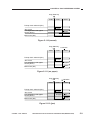
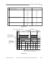
2.
Relationship between Scanner Sensor and Signal
Scanner sensor
PS1(scanner
home position
sensor)
Scanner
Forward
Reverse
Signal
Description
• Provides a means of reference for
determining forward movement
distance.
• Stops the scanner moving in reverse in 0.1 sec.
SCHP
Table 3-102
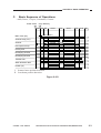
3.
,,
Basic Sequence of Operations (scanner)
Power switch Copy Start key
ON
ON
STBY
Scanner home position
sensor (PS1)
Pre-registration roller
paper sensor (Q751)
Scanner
Scanning lamp(LA1)
I
II
INTR
SCFW
SCRV
I
Forward
Reverse
SCFW
SCRV LSTR STBY
I: Scanner home position detection
II: Lens home position detection
Figure 3-105
The microprocessor on the DC controller PCB controls the forward movement distance of the
scanner with reference to the falling edge of the scanner home position signal. The forward movement distance of the scanner varies according to the length of copy paper and reproduction ratio. If
the ratio is less than 130%, the scanner is moved forward as if for A4 (297 mm); if it is 130% or
more, the scanner is moved forward as if for LTR (279 mm).
*For descriptions on how length is detected, see p. 5-7.
COPYRIGHT © 1999 CANON INC.
CANON NP6512/6612/7120/7130/7130F REV.0 AUG. 1999 PRINTED IN JAPAN (IMPRIME AU JAPON)
3-5
CHAPTER 3 EXPOSURE SYSTEM
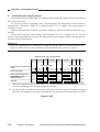
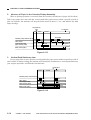
4.
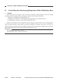
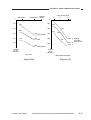
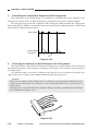
Controlling the Copying Speed
The machine uses a halogen lamp for scanning, and the heat of the lamp increases the temperature of the copyboard.
To prevent possible overheating of the copyboard glass, the temperature of the scanner is
monitored by a thermistor (TH2); if its reading reaches 37.5°C or higher, the copying speed is
reduced to 6 cpm.
If this mechanism turns on during continuous copying, it remains on until the end of the copying job.
At the end of copying, if the reading of the thermistor is 34.5°C or higher, the No. 1 mirror
mount is moved forward 105 mm from the home position and stopped, thereby lowering the temperature of the copyboard fast.
Reference:
While the copying speed is controlled to 6 cpm, the speed of the reverse movement of the
scanner is reduced to prevent overheating of the copyboard glass. (about 75 mm/sec)
,,,
Switching to 6-cpm copying speed
SCRV
Check timing by thermistor
(TH2)
Main motor (M1)
SCFW
SCRV
SCFW
37.5˚C or higher
Pickup clutch solenoid (SL1)
Registration clutch
solenoid (SL2)
Scanner
I:
SCRV
SCFW
SCRV LSTR STBY
34.5˚C or higher
I
II
When the registration clutch solenoid (SL2) is off, the pickup clutch solenoid is turned off to
prevent overheating of the pickup clutch solenoid (SL1).
II: By the time the Copy Start key is pressed or the power switch is turned off and then on again
next time, the scanner is moved to and stopped at 105 mm forward from the home position.
Figure 3-106
3-6
COPYRIGHT © 1999 CANON INC.
CANON NP6512/6612/7120/7130/7130F REV.0 AUG. 1999 PRINTED IN JAPAN (IMPRIME AU JAPON)
CHAPTER 3 EXPOSURE SYSTEM
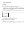
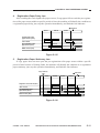
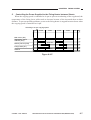
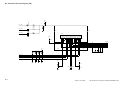
5.
a.
Controlling the Scanner/Lens Drive Motor
Outline
The scanner/lens drive motor (M2) is a 4-phase stepping motor. The timing at which the drive
power (SC-COM) and pulses (SC-A, SCA*, SC-B, SC-B*) are generated is controlled to turn on/
off the scanner/lens drive motor (M2) or to switch the direction of its rotation.
DC controller PCB
+24VU
R399
J110
SC-COM
(Q101)
SC-COM
(Q109)
Microprocessor
A
A*
SC-A
B
SC-A*
B*
Motor
driver
circuit
SC-B
SC-B*
M2
Current switching signal 1
Current switching signal 2
Current switching signal 3
Figure 3-107
COPYRIGHT © 1999 CANON INC.
CANON NP6512/6612/7120/7130/7130F REV.0 AUG. 1999 PRINTED IN JAPAN (IMPRIME AU JAPON)
3-7
CHAPTER 3 EXPOSURE SYSTEM
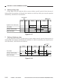
b.
Operations
The microprocessor (Q101) mounted on the DC controller PCB receives instructions from the
control panel PCB copying mode settings (e.g., reproduction ratio). In response, it applies drive
pulses to the scanner/lens drive motor (M2) through the motor driver circuit.
The scanner motor is a 4-phase stepping motor, and changes the direction and speed of its
rotation according to the sequence and frequency of drive pulses (SC-A*through SC-B*).
The motor drive voltage is switched on and off by pulse signals (A through B*) generated by
the microprocessor (Q101). Any of these pulse signals is generated when the motor is in operation,
while no pulse signal is generated when the motor is at rest.
The current switching signals from 1 to 3 generated by the microprocessor (Q101) are used to
control the current flowing to the motor so that it varies according to the state of the scanner and the
lens.
Starting the lens
Moving the lens
Current switching signal 1
0
Current switching signal 2
Current switching signal 3
0
Reversing the
scanner
0
Forwarding the
scanner
1
0
0
1
1
0
1
1
1
c.
Detecting Overcurrent for the Scanner/Lens Drive Motor
If overcurrent flows to the scanner/lens drive motor for some reason, the fuse (R339) on the DC
controller PCB will blow to cut the power to the motor.
Caution:
The fuse (R339) will not recover once it has blown.
3-8
COPYRIGHT © 1999 CANON INC.
CANON NP6512/6612/7120/7130/7130F REV.0 AUG. 1999 PRINTED IN JAPAN (IMPRIME AU JAPON)
CHAPTER 3 EXPOSURE SYSTEM
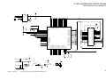
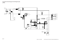
II. EXPOSURE SYSTEM
A.
Controlling the Scanning Lamp
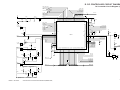
1.
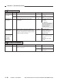
Outline
Figure 3-201 shows the circuit used to control the scanning lamp, and has the following functions:
• Turning on/off the scanning lamp.
• Controlling the intensity of the scanning lamp.
• Monitoring the state (on/off) of the scanning lamp.
(Q900)
Intensity adjustment
signal
PWM_1KHz
4
(Q101)
Phase
2
control
circuit
Microprocessor
Serial
communication
Microprocessor
Rectifying
circuit
9
Lamp activation
signal
+
+
-
Thermal fuse
(FU1)
Scanning lamp
(LA1)
7
LAMP_ON
(HIC001)
Arcing circuit
Activation detection
signal
Rectifying
circuit
LAMP_DETECT
Activation detection circuit
DC controller PCB
Composite power supply PCB
Figure 3-201
COPYRIGHT © 1999 CANON INC.
CANON NP6512/6612/7120/7130/7130F REV.0 AUG. 1999 PRINTED IN JAPAN (IMPRIME AU JAPON)
3-9
CHAPTER 3 EXPOSURE SYSTEM
2.
a.
Operations
Turning On/Off the Scanning Lamp
The DC controller PCB and the composite power supply exchange signals in serial communication to control the scanning lamp. According to the scanner lamp active voltage signal, the microprocessor (Q900) on the composite power supply PCB controls the intensity adjustment signal
(PWM_1KHz) and the lamp activation signal (LAMP_ON) to turn on/off the scanning lamp
(LA1).
When LAMP_ON is ‘0’,
The phase control circuit turns on.
The arcing circuit turns on.
The scanning lamp turns on.
When LAMP_ON is ‘1’,
The phase control circuit turns off.
The arcing circuit turns off.
The scanning lamp turns off.
3-10
COPYRIGHT © 1999 CANON INC.
CANON NP6512/6612/7120/7130/7130F REV.0 AUG. 1999 PRINTED IN JAPAN (IMPRIME AU JAPON)
CHAPTER 3 EXPOSURE SYSTEM
b.
Controlling the Intensity of the Scanning Lamp
The intensity of the lamp is controlled by the scanning lamp active voltage signal sent by the
DC controller PCB in serial.
The microprocessor (Q900) on the composite power supply PCB sends the intensity adjustment signal (PWM_1KHz) in response to the scanning lamp active voltage signal. In turn, the
phase control circuit (HIC001) controls the voltage supplied to the scanning lamp.
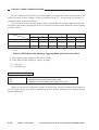
The PWM_1KHz signal varies according to settings made in service mode. In relation to the
settings, the composite power supply PCB executes phase control so that variation will be between
10% and 90% in terms of pulse duty ratios and between 50.5 and 80 V for the 120V model (between 85.7 and 145.8 V for the 220/240V model) in terms of actual value.
The intensity during AE exposure remains a specific level, which is 56 V for the 120 V model
(108.5 V for the 220/240V model) in terms of actual values.
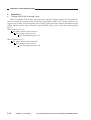
t [msec]
<PWM_1KHz signal>
ON
OFF
1
[msec]
1kHz
1
Pulse duty= t/ 1k × 100 [%]
Figure 3-202
Related Service Mode
38 (LAMP_ADJ)
COPYRIGHT © 1999 CANON INC.
Use it to adjust the intensity of the scanning lamp.
CANON NP6512/6612/7120/7130/7130F REV.0 AUG. 1999 PRINTED IN JAPAN (IMPRIME AU JAPON)
3-11
CHAPTER 3 EXPOSURE SYSTEM
c.
Monitoring the Activation of the Scanning Lamp
The activation detection signal (LAMP_DETECT) is sent to the microprocessor (Q900) on the
composite power supply PCB as long as the scanning lamp remains on.
The composite power supply PCB sends the lamp activation signal to the DC controller PCB in
serial by way of monitoring the activation of the scanning lamp (LA1).
Related Error Code
E220
• The lamp activation detection signal is not detected for 1 sec or more although the scanning lamp activation signal has been sent.
• The lamp activation detection signal has been detected for 1 sec or more although the
scanning lamp activation signal is not sent.
If an error has been detected, the power switch will be turned off after indicating an error code
for 2 sec.
d.
Scanning Lamp Intensity Auto Correction Control (ALVC control)
The machine automatically corrects the activation voltage of the scanning lamp to make up for
the change in copy image quality caused by deterioration/wear of the photosensitive drum.
3-12
COPYRIGHT © 1999 CANON INC.
CANON NP6512/6612/7120/7130/7130F REV.0 AUG. 1999 PRINTED IN JAPAN (IMPRIME AU JAPON)
CHAPTER 3 EXPOSURE SYSTEM
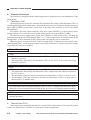
III. DISASSEMBLY/ASSEMBLY
As needed, disassemble/assemble the machine with the following in mind:
1. ! Before starting the work, turn off the power switch and disconnect the power plug for
safety.
2. Unless otherwise instructed, assemble the parts by reversing the steps used to disassemble
it.
3. Identify the screws by type (length, diameter) and location.
4. Use the washers where necessary. (The screws used to mount the grounding wire and Varistors come with a washer to ensure electrical continuity.)
5. As necessary, cut the harness band.
6. As a rule, do not operate the machine with any of its part removed.
7. A few of the screws used are special screws (with wider thread intervals). Do not use any
screws indiscriminately.
COPYRIGHT © 1999 CANON INC.
CANON NP6512/6612/7120/7130/7130F REV.0 AUG. 1999 PRINTED IN JAPAN (IMPRIME AU JAPON)
3-13
CHAPTER 3 EXPOSURE SYSTEM
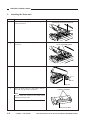
A.
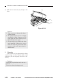
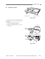
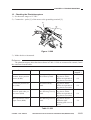
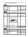
Scanner Drive Assembly
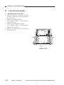
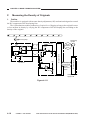
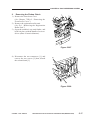
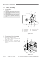
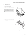
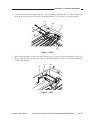
1.
Removing the Scanner/Lens Drive
Motor
Remove the front lower cover.
(See Chapter 7.III.A.2. “Removing the
Front Lower Cover.”)
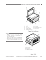
Remove the developing assembly.
(See Chapter 4.II.D.2. “Removing the Developing assembly.”)
Remove the copyboard glass.
(See Chapter 7.III.C.1. “Removing the
Copyboard Glass.”)
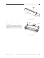
Remove the four screws [1], and detach
the lens cover [2].
1)
2)
3)
4)
[1]
[1]
[2]
Figure 3-301
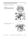
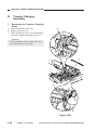
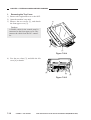
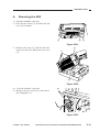
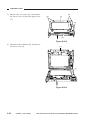
5) Disconnect the connector (J110) [3] from
the DC controller PCB.
[3]
Figure 3-302
3-14
COPYRIGHT © 1999 CANON INC.
CANON NP6512/6612/7120/7130/7130F REV.0 AUG. 1999 PRINTED IN JAPAN (IMPRIME AU JAPON)
CHAPTER 3 EXPOSURE SYSTEM
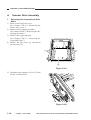
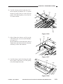
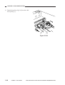
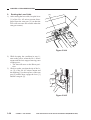
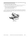
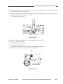
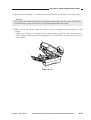
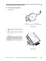
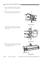
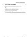
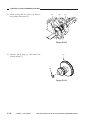
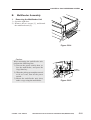
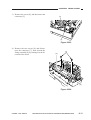
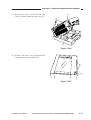
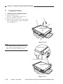
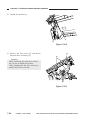
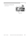
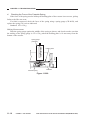
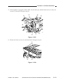
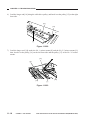
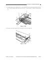
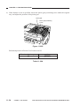
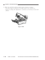
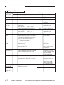
6) Open the machine’s top unit farther, and
hold it in position using the handle (about
30 mm in diameter) of a screwdriver.
Figure 3-303
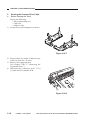
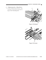
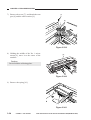
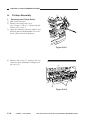
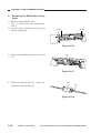
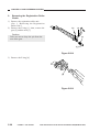
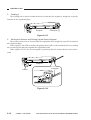
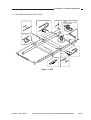
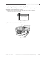
7) Remove the two fixing screws [4] from
the scanner/lens drive motor [5].
[5]
[4]
Figure 3-304
COPYRIGHT © 1999 CANON INC.
CANON NP6512/6612/7120/7130/7130F REV.0 AUG. 1999 PRINTED IN JAPAN (IMPRIME AU JAPON)
3-15
CHAPTER 3 EXPOSURE SYSTEM
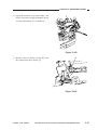
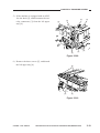
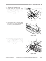
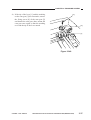
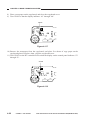
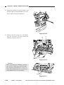
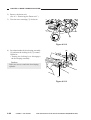
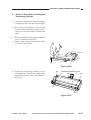
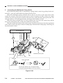
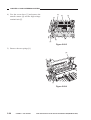
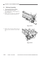
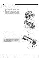
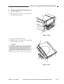
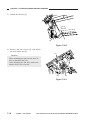
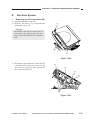
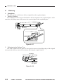
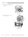
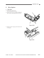
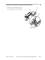
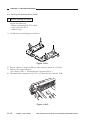
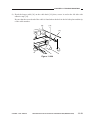
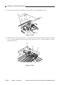
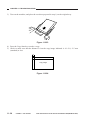
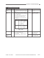
8) Free the top unit (by removing the screwdriver), and close the top unit.
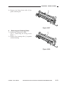
9) Remove the E-ring [6]; then, lift the cable
drive pulley [7] slightly, and detach the
scanner/lens drive motor [5].
[6]
Lift.
[5]
[7]
Figure 3-305
3-16
COPYRIGHT © 1999 CANON INC.
CANON NP6512/6612/7120/7130/7130F REV.0 AUG. 1999 PRINTED IN JAPAN (IMPRIME AU JAPON)
CHAPTER 3 EXPOSURE SYSTEM
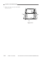
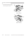
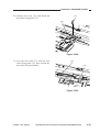
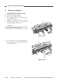
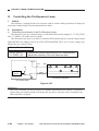
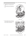
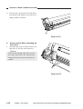
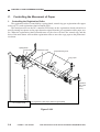
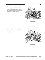
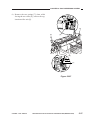
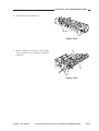
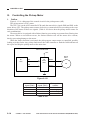
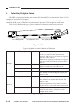
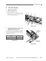
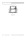
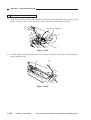
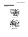
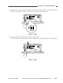
2.
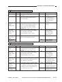
Outline of the Scanner Drive Cable
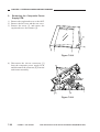
Wind 1.5 times.
(black cable)
Wind 7.5 times.
(silver-colored cable)
Figure 3-306
COPYRIGHT © 1999 CANON INC.
CANON NP6512/6612/7120/7130/7130F REV.0 AUG. 1999 PRINTED IN JAPAN (IMPRIME AU JAPON)
3-17
CHAPTER 3 EXPOSURE SYSTEM
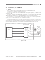
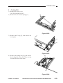
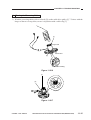
3.
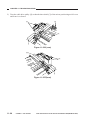
a.
Routing the Scanner Drive Cable
Before Starting the Work
Prepare the following:
• Mirror positioning tool
• Cable clip
• Adhesive tape
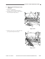
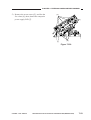
1) Set the mirror positioning tool as shown.
Figure 3-307
2) Prepare about five strips of adhesive tape
(each one about 20 × 50 mm).
3) Remove the copyboard glass.
(See Chapter 7.III.C.1. “Removing the
Copyboard Glass.”)
4) Disconnect the connectors (J101, J131)
[1] from the DC controller PCB.
[1]
Figure 3-308
3-18
COPYRIGHT © 1999 CANON INC.
CANON NP6512/6612/7120/7130/7130F REV.0 AUG. 1999 PRINTED IN JAPAN (IMPRIME AU JAPON)
CHAPTER 3 EXPOSURE SYSTEM
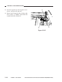
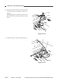
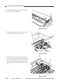
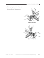
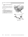
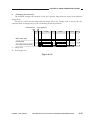
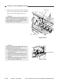
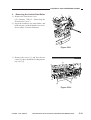
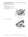
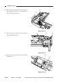
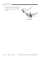
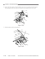
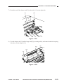
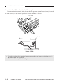
5) If the machine is equipped with an ADF,
free the hook [2], and disconnect the two
relay connectors [3] from the left upper
stay [4].
[4]
[2]
[3]
[2]
[3]
[2]
[2]
Figure 3-309
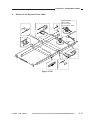
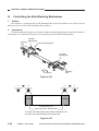
6) Remove the three screws [5], and detach
the left upper stay [4].
[5]
[5]
[4]
Figure 3-310
COPYRIGHT © 1999 CANON INC.
CANON NP6512/6612/7120/7130/7130F REV.0 AUG. 1999 PRINTED IN JAPAN (IMPRIME AU JAPON)
3-19
CHAPTER 3 EXPOSURE SYSTEM
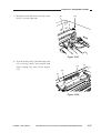
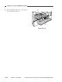
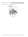
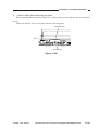
7) Remove the four screws [6], and detach
the lens cover [7].
[6]
[6]
[7]
Figure 3-311
3-20
COPYRIGHT © 1999 CANON INC.
CANON NP6512/6612/7120/7130/7130F REV.0 AUG. 1999 PRINTED IN JAPAN (IMPRIME AU JAPON)
CHAPTER 3 EXPOSURE SYSTEM
b. Routing the Reversing Cable
1) Wind the reversing cables (silver-colored)
[2] on the cable drive pulley [1] 7.5 times
with the longer end on top; then, secure it
in position with a cable clip [3].
[1]
Longer end
Shorter end
[2]
Face with a marking
Figure 3-312
[3]
[1]
[3]
Top View
Figure 3-313
COPYRIGHT © 1999 CANON INC.
CANON NP6512/6612/7120/7130/7130F REV.0 AUG. 1999 PRINTED IN JAPAN (IMPRIME AU JAPON)
3-21
CHAPTER 3 EXPOSURE SYSTEM
2) Put the cable drive pulley [1] into the shaft
[4], and secure it in position with an Ering [5].
When putting the cable drive pulley into
the shaft, be sure that the hook is at the
front.
[5]
Hook
[1]
(front)
[4]
Figure 3-314
3) Hook the shorter end [6] on the pulley [7].
[7]
[6]
Figure 3-315
3-22
COPYRIGHT © 1999 CANON INC.
CANON NP6512/6612/7120/7130/7130F REV.0 AUG. 1999 PRINTED IN JAPAN (IMPRIME AU JAPON)
CHAPTER 3 EXPOSURE SYSTEM
4) Lead the shorter end [6] under the No. 1
mirror mount [8] and the No. 2/3 mirror
mount [9]; then, hook it on the left rear
pulley [10] and the pulley [11] of the No.
2/3 mirror mount.
[11]
[9]
[8]
[10]
[6]
Figure 3-316
5) After fitting the shorter end [6] on the
cable hook [12], secure its end with adhesive tape [13].
Be sure that the secured end of the cable is
found where the hole in the left side plate
and the tip of the cable matches.
[13]
[12]
[6]
Figure 3-317
6) Lead the longer end [14] along the cable
drive pulley, and hook it on the pulley
[15] on the right front side.
[14]
[15]
Figure 3-318
COPYRIGHT © 1999 CANON INC.
CANON NP6512/6612/7120/7130/7130F REV.0 AUG. 1999 PRINTED IN JAPAN (IMPRIME AU JAPON)
3-23
CHAPTER 3 EXPOSURE SYSTEM
7) Lead the longer end [14] under the No. 1
mirror mount [8] and the No. 2/3 mirror
mount [9]; then, hook it on the pulley [16]
on the left front side and the pulley [17] of
the No. 2/3 mirror mount.
[17]
[8]
[16]
[14]
[9]
Figure 3-319
8) Hook the longer end [14] on the cable
hook [18]; then, secure its end to the left
side with adhesive tape [19].
Be sure that the secured end of the cable is
found where the hole in the left side plate
and the tip of the cable matches.
[18]
[19]
[14]
Figure 3-320
3-24
COPYRIGHT © 1999 CANON INC.
CANON NP6512/6612/7120/7130/7130F REV.0 AUG. 1999 PRINTED IN JAPAN (IMPRIME AU JAPON)
CHAPTER 3 EXPOSURE SYSTEM
c. Routing the Forwarding Cable
1) Fit the longer end forwarding cable
(black) [2] on the top hook of the cable
drive pulley [1], and wind it 1.5 times.
Then, secure the shorter end [3] as shown
with adhesive tape [4].
[4]
Face without a marking
[3]
[2]
[1]
Figure 3-321
2) Lead the longer end [5] along the cable
drive pulley [1] as shown, and hook it on
the pulley [6] on the right front side.
[1]
[5]
[6]
Figure 3-322
[8]
3) Lead the longer end [5] under the No. 1
mirror mount [7]; then, hook it on the pulley [8] of the No. 2/3 mirror mount, and
lead it between the No. 1 mirror mount [7]
and the scanning lamp [9].
[7]
[9]
[5]
Figure 3-323
COPYRIGHT © 1999 CANON INC.
CANON NP6512/6612/7120/7130/7130F REV.0 AUG. 1999 PRINTED IN JAPAN (IMPRIME AU JAPON)
3-25
CHAPTER 3 EXPOSURE SYSTEM
4) Hook the end of the longer end [5] on the
hole [10] on the right side.
[10]
[5]
Figure 3-324
5) Free the shorter end [3], and hook it on the
pulley [11] on the right rear side.
[3]
[11]
Figure 3-325
6) Lead the shorter end [3] under the No. 1
mirror mount [7], and hook it on the pulley [12] of the No. 2/3 mirror mount as
shown; then, lead it between the No. 1
mirror mount [7] and the scanning lamp
[9].
[12]
[3]
[9]
[7]
Figure 3-326
3-26
COPYRIGHT © 1999 CANON INC.
CANON NP6512/6612/7120/7130/7130F REV.0 AUG. 1999 PRINTED IN JAPAN (IMPRIME AU JAPON)
CHAPTER 3 EXPOSURE SYSTEM
7) Hook the end of the shorter end [3] on the
hole [13] on the right side.
[3]
[13]
Figure 3-327
8) Free the shorter end [3] and the longer end
[5] (reversing cable), and connect both
with a spring [14]; then, fit the stopper
[15].
[14]
[3]
[15]
[5]
Figure 3-328
COPYRIGHT © 1999 CANON INC.
CANON NP6512/6612/7120/7130/7130F REV.0 AUG. 1999 PRINTED IN JAPAN (IMPRIME AU JAPON)
3-27
CHAPTER 3 EXPOSURE SYSTEM
9) Detach the pulley clip [16] from the cable
drive pulley [1].
[1]
[16]
Figure 3-329
3-28
COPYRIGHT © 1999 CANON INC.
CANON NP6512/6612/7120/7130/7130F REV.0 AUG. 1999 PRINTED IN JAPAN (IMPRIME AU JAPON)
CHAPTER 3 EXPOSURE SYSTEM
d. Positioning the No. 1 Mirror Mount
1) Fix the rear and the front of the No. 1 mirror mount [1] temporarily to the metal fixing [2] of the forwarding cable.
[1]
[2]
Figure 3-330 (front)
[2]
[1]
Figure 3-331 (rear)
COPYRIGHT © 1999 CANON INC.
CANON NP6512/6612/7120/7130/7130F REV.0 AUG. 1999 PRINTED IN JAPAN (IMPRIME AU JAPON)
3-29
CHAPTER 3 EXPOSURE SYSTEM
2) Turn the cable drive pulley [4] so that the
three shafts [3] of the mirror positioning
tool for rear and front is as shown.
[3]
[4]
[3]
Figure 3-332 (rear)
[3]
[3]
Figure 3-333 (front)
3-30
COPYRIGHT © 1999 CANON INC.
CANON NP6512/6612/7120/7130/7130F REV.0 AUG. 1999 PRINTED IN JAPAN (IMPRIME AU JAPON)
CHAPTER 3 EXPOSURE SYSTEM
3) While keeping the condition of step 2),
tighten the positioning screw on the rear
and front of the No. 1 mirror mount [1].
[1]
Figure 3-334 (rear)
[1]
Figure 3-335 (front)
COPYRIGHT © 1999 CANON INC.
CANON NP6512/6612/7120/7130/7130F REV.0 AUG. 1999 PRINTED IN JAPAN (IMPRIME AU JAPON)
3-31
CHAPTER 3 EXPOSURE SYSTEM
B.
Lens Drive Assembly
1. Removing the Lens Cable
1) Turn on the power; when the lens has
moved to the Direct position, disconnect
the power plug.
2) Remove the copyboard glass.
(See Chapter 7.III.C.1. “Removing the
Copyboard Glass.”)
3) Remove the main drive assembly.
(See Chapter 7.III.D.2. “Removing the
Main Drive Assembly.”)
4) Remove the four screws [1], and detach
the lens cover [2].
[1]
[1]
[2]
Figure 3-336
3-32
COPYRIGHT © 1999 CANON INC.
CANON NP6512/6612/7120/7130/7130F REV.0 AUG. 1999 PRINTED IN JAPAN (IMPRIME AU JAPON)
CHAPTER 3 EXPOSURE SYSTEM
5) Mark the position of the lens cable fixing
plate [3] and the lens mount [4] with a
scriber.
[3]
Marking
Caution:
When routing the lens cable, be sure to
refer to the marking made with a scriber.
[4]
Figure 3-337
6) Disengage the lever [5] of the No. 4/5 mirror mount and the gear [6].
[6]
[5]
Figure 3-338
COPYRIGHT © 1999 CANON INC.
CANON NP6512/6612/7120/7130/7130F REV.0 AUG. 1999 PRINTED IN JAPAN (IMPRIME AU JAPON)
3-33
CHAPTER 3 EXPOSURE SYSTEM
7) Remove the screw [7], and detach the cam
gear [6] and the cable retainer [8].
[7]
[6]
[8]
Figure 3-339
8) Holding the middle of the No. 1 mirror
mount [9], move it to the center of the
machine.
[9]
Caution:
Do not hold the reflecting plate.
Figure 3-340
9) Remove the spring [10].
[10]
Figure 3-341
3-34
COPYRIGHT © 1999 CANON INC.
CANON NP6512/6612/7120/7130/7130F REV.0 AUG. 1999 PRINTED IN JAPAN (IMPRIME AU JAPON)
CHAPTER 3 EXPOSURE SYSTEM
10) Remove the screw [11], and detach the
lens cable fixing plate [12].
[11]
[12]
Figure 3-342
11) Free the lens cable [13] from the lens
cable fixing plate [12]; then, detach the
lens cable from the machine.
[13]
[12]
Figure 3-343
COPYRIGHT © 1999 CANON INC.
CANON NP6512/6612/7120/7130/7130F REV.0 AUG. 1999 PRINTED IN JAPAN (IMPRIME AU JAPON)
3-35
CHAPTER 3 EXPOSURE SYSTEM
2. Routing the Lens Cable
1) After routing the lens cable, keep the lever
[1] of the No. 4/5 mirror mount disengaged from the cam gear [2] (so that the
lever will not come into contact when the
cam gear rotates).
[2]
[1]
Figure 3-344
2) While keeping the condition in step 1),
turn on the power; when the No. 1 mirror
mount and the lens stopped moving, turn
off the power.
• The lens will move to the Direct position.
3) Check to make sure that the tip of the lever [1] of the No. 4/5 mirror mount and
the marking [3] on the top face of the cam
gear [2] match; then, engage the lever [1]
and the cam gear [2].
[2]
[3]
[1]
Figure 3-345
3-36
COPYRIGHT © 1999 CANON INC.
CANON NP6512/6612/7120/7130/7130F REV.0 AUG. 1999 PRINTED IN JAPAN (IMPRIME AU JAPON)
CHAPTER 3 EXPOSURE SYSTEM
4) If the tip of the lever [1] and the marking
on the cam gear [2] do not match, remove
the fixing screw [4] of the cam gear [2]
and detach the cam gear; then, mount the
cam gear once again so that the marking
on it and the tip of the lever match.
[4]
[2]
[1]
Figure 3-346
COPYRIGHT © 1999 CANON INC.
CANON NP6512/6612/7120/7130/7130F REV.0 AUG. 1999 PRINTED IN JAPAN (IMPRIME AU JAPON)
3-37
CHAPTER 3 EXPOSURE SYSTEM
C.
Exposure System
1. Removing the Scanning Lamp
1) Disconnect the power plug.
2) Remove the copyboard glass.
(See Chapter 7.III.C.1. “Removing the
Copyboard Glass.”)
3) Holding the middle of the No. 1 mirror
mount [1], move the No. 1 mirror mount
[1] to the right by about 5 cm.
[1]
Caution:
Do not hold the reflecting plate.
Figure 3-347
4) Free the harness [3] from the guide [2];
then, remove the screw [4], and detach the
reflecting plate [5].
[4]
[5]
[3]
[2]
Figure 3-348
3-38
COPYRIGHT © 1999 CANON INC.
CANON NP6512/6612/7120/7130/7130F REV.0 AUG. 1999 PRINTED IN JAPAN (IMPRIME AU JAPON)
CHAPTER 3 EXPOSURE SYSTEM
5) While pushing the electrode mount [6]
found at the rear of the machine in the direction of the arrow, detach the scanning
lamp [7].
Caution:
1. Do not start the work if the scanning
lamp is hot.
2. Do not leave fingerprints on the surface of the scanning lamp.
3. If the surface of the scanning lamp is
soiled, dry wipe it.
[6]
[7]
Figure 3-349
COPYRIGHT © 1999 CANON INC.
CANON NP6512/6612/7120/7130/7130F REV.0 AUG. 1999 PRINTED IN JAPAN (IMPRIME AU JAPON)
3-39
CHAPTER 3 EXPOSURE SYSTEM
2.
Points to Note When Mounting the
Lamp
When mounting the scanning lamp, be
sure that the logo mark (or the name of the
manufacturer) is toward the front. Further, be
sure that the protrusion near the middle of the
lamp is as shown.
Caution:
• Do not touch the lamp portion.
• If you have replaced the scanning
lamp, be sure to perform intensity adjustment (p. 11-42) and AE adjustment (p. 11-44).
Logo mark
(front)
Scanning lamp
(mirror mount moving in reverse)
45˚ (approx.)
Figure 3-350
3-40
COPYRIGHT © 1999 CANON INC.
CANON NP6512/6612/7120/7130/7130F REV.0 AUG. 1999 PRINTED IN JAPAN (IMPRIME AU JAPON)
CHAPTER 3 EXPOSURE SYSTEM
3. Removing the Thermal Fuse
1) Disconnect the power plug.
2) Remove the copyboard glass.
(See Chapter 7.III.C.1. “Removing the
Copyboard Glass.”)
3) Remove the two screws [1], and detach
the thermal fuse [2].
[2]
[1]
Figure 3-351
4.
Points to Note When Mounting the
Fuse
When mounting the thermal fuse, be sure
that the thermal fuse is oriented as shown.
Make sure that the fuse is in contact with
the reflecting plate.
Reflecting plate
(front)
Thermal fuse
Figure 3-352
COPYRIGHT © 1999 CANON INC.
CANON NP6512/6612/7120/7130/7130F REV.0 AUG. 1999 PRINTED IN JAPAN (IMPRIME AU JAPON)
3-41
CHAPTER 3 EXPOSURE SYSTEM
5. Removing the Thermistor Unit
1) Remove the top cover.
(See Chapter 7.III.A.1. “Removing the
Top Cover.”)
2) Disconnect the connector (J131) [1] from
the DC controller PCB; remove the screw
[2], and detach the thermistor unit [3].
[3]
[2]
[1]
Figure 3-353
3-42
COPYRIGHT © 1999 CANON INC.
CANON NP6512/6612/7120/7130/7130F REV.0 AUG. 1999 PRINTED IN JAPAN (IMPRIME AU JAPON)
CHAPTER 4
IMAGE FORMATION SYSTEM
This chapter discusses the principles of how images are formed. It also explains the
timing at which the various units involved in image formation are operated, and shows
how they may be disassembled/assembled and adjusted.
I.
IMAGE FORMATION SYSTEM ...4-1
A. Outline ...................................4-1
B. Timing Chart for the Image
Formation System .................4-3
C. Primary Charging Roller Bias
Control ...................................4-4
D. Controlling the Transfer Roller
Bias .......................................4-9
E. Controlling the Developing/
Separation Static Eliminator
Bias .................................... 4-12
F. Measuring the Density of
Originals ............................. 4-18
G. Controlling the Pre-Exposure
Lamp .................................. 4-24
H. Controlling the Side Blanking
Mechanism ......................... 4-26
COPYRIGHT © 1999 CANON INC.
II.
DEVELOPING ASSEMBLY
/CLEANING ASSEMBLY ...........
A. Outline ................................
B. Detecting the Level of
Toner ..................................
C. Detecting Waste Toner .......
D. Primary Charging Roller
Cleaning Control ................
III. DISASSEMBLY/ASSEMBLY .....
A. Drum Unit ...........................
B. Transfer Charging
Assembly ............................
C. Blank Exposure ..................
D. Developing Assembly .........
CANON NP6512/6612/7120/7130/7130F REV.0 AUG. 1999 PRINTED IN JAPAN (IMPRIME AU JAPON)
4-27
4-27
4-28
4-30
4-31
4-33
4-34
4-38
4-39
4-43
CHAPTER 4 IMAGE FORMATION SYSTEM
I.
A.
IMAGE FORMATION SYSTEM
Outline
The major functions of the image formation system are as follows:
Item
Primary charging roller bias control
Description
DC constant voltage control: on/off
DC voltage level switching
DC voltage level auto correction
Transfer roller bias control
DC constant voltage control: on/off
DC constant current control (ATVC, cleaning bias)
Voltage level control
Polarity switching control
Developing/separation static eliminator bias control
DC constant voltage control:
AC constant voltage control:
DC voltage level control
Density control
Developing DC bias control
Pre-exposure control
Pre-exposure lamp
Blank exposure control
Side blanking exposure lamp
Toner level detection
Level detection by a waste toner sensor
Waste toner case full detection
Detection by a waste toner sensor
Primary charging roller cleaning
Auto cleaning by the cleaning pad
on/off
on/off
Table 4-101
COPYRIGHT © 1999 CANON INC.
CANON NP6512/6612/7120/7130/7130F REV.0 AUG. 1999 PRINTED IN JAPAN (IMPRIME AU JAPON)
4-1
CHAPTER 4 IMAGE FORMATION SYSTEM
Copyboard glass
Scanning lamp
Lens
AE sensor
Side blanking
exposure lamp
Developing
cylinder
Pre-exposure lamp
Primary charging roller
Photosensitive
drum
Static
eliminator
Q101
Lamp regulator
block
Transfer
roller
High-voltage
circuit block
Microprocessor
Q900
DC controller PCB
Microprocessor
Composite power supply PCB
Figure 4-101
4-2
COPYRIGHT © 1999 CANON INC.
CANON NP6512/6612/7120/7130/7130F REV.0 AUG. 1999 PRINTED IN JAPAN (IMPRIME AU JAPON)
CHAPTER 4 IMAGE FORMATION SYSTEM
B.
Timing Chart for the Image Formation System
Basic Sequence of Operations (Direct, 2 copies, continuous)
Copy Start key
ON
STBY INTR
Main motor (M1)
Scanning lamp (LA1)
Scanner
Pre-exposure lamp
Primary bias
Developing AC bias
Developing DC bias
Transfer bias
Transfer cleaning bias
Transfer reference
bias (ATVC)
Static eliminator bias
Pre-registration roller
paper sensor (Q751)
SCFW
SCRV
forward
Reverse
SCFW
SCRV
LSTR STBY
-500V
0.6sec.(approx.)
3200V
Figure 4-102
COPYRIGHT © 1999 CANON INC.
CANON NP6512/6612/7120/7130/7130F REV.0 AUG. 1999 PRINTED IN JAPAN (IMPRIME AU JAPON)
4-3
CHAPTER 4 IMAGE FORMATION SYSTEM
C.
Primary Charging Roller Bias Control
1.
Outline
Figure 4-103 shows the circuit used to control the voltage applied to the primary charging
roller, and has the following functions:
• Turning on and off the DC bias.
• Controls the DC bias to a constant voltage.
• Switching the level of the DC bias.
• Corrects the level of the DC bias automatically.
The level of the DC bias applied to the primary charging roller is switched between image area
and non-image area.
Reference:
The level of the DC bias is as follows:
Image area:
-1376 V ± (correction value by APVC) ± (correction value * by density mode)
Non-image area: -900 V ± (correction value by APVC); area between sheets
-1000 V ± (correction value by APVC); cleaning area by transfer
-600 V ± (correction value by APVC); trailing edge area
*See p. 4-16.
4-4
COPYRIGHT © 1999 CANON INC.
CANON NP6512/6612/7120/7130/7130F REV.0 AUG. 1999 PRINTED IN JAPAN (IMPRIME AU JAPON)
CHAPTER 4 IMAGE FORMATION SYSTEM
Main
transformer
T101
Primary
charging
roller
Voltage
separation
circuit
PDC_S
DC voltage monitor signal
PDC_PWM
DC bias control signal
P_C_S
DC bias current detection signal
Photosensitive
drum
PR_DC_ON
J103
-5
J203
-5
Microprocessor (Q900)
Composite power supply PCB
Serial communication
Microprocessor (Q101)
DC controller PCB
Figure 4-103
COPYRIGHT © 1999 CANON INC.
CANON NP6512/6612/7120/7130/7130F REV.0 AUG. 1999 PRINTED IN JAPAN (IMPRIME AU JAPON)
4-5
CHAPTER 4 IMAGE FORMATION SYSTEM
2.
a.
Operations
Turning On and Off the DC Bias
The DC bias applied to the primary charging roller is turned on or off by the serial communication signal and the primary charging bias ON signal (PR_DC_ON) from the DC controller PCB.
When the Copy Start key is pressed, the DC bias ON signal (serial) and the primary charging
bias ON signal (PR_DC_ON) are sent. The microprocessor (Q900) on the composite power supply
PCB generates the DC bias control signal (PDC_PWM) based on the combination of the serial
signal and the PR_DC_ON signal, applying a DC bias to the primary charging roller.
DC bias ON
(image area)
DC bias ON
(non-image area)*1
DC bias ON
(non-image area)*2
DC bias ON
(APVC)
DC bias OFF
DC bias ON signal
(8-bit signal communication)
bit0
bit1
1
–
PR_DC_ON
(J103-5)
0
1
0
1
1
1
1
0
–
0
0
0
1
*1: Area between sheets
*2: Cleaning area by transfer / trailing edge area
Table 4-102 Relationship between DC Bias Output and Signal
b.
Controlling the DC Bias to a Specific Voltage/Current
The DC bias applied to the primary charging roller is controlled by the microprocessor (Q900)
on the composite power supply PCB so that it remains a specific level.
When a DC bias is generated, the microprocessor (Q900) on the composite power supply PCB
detects the DC voltage monitor signal (PDC_S), compares its level against the reference level, and
varies the DC bias control signal (PDC_PWM) according to the difference so as to ensure that it
remains specific level.
Reference:
The DC bias control signal varies its pulse duty ratio to change the level of the DC bias.
4-6
COPYRIGHT © 1999 CANON INC.
CANON NP6512/6612/7120/7130/7130F REV.0 AUG. 1999 PRINTED IN JAPAN (IMPRIME AU JAPON)
CHAPTER 4 IMAGE FORMATION SYSTEM
c.
Switching the DC Bias Level
The machine changes the level of its DC bias according to the following: copying image area,
sheet-to-sheet distance, and image trailing edge margin. In addition, it is also switched while a
cleaning bias is applied by the transfer roller, during which the primary charging roller applies a
negative DC bias to prevent the photosensitive drum from being charged to a positive potential.
The level of the DC bias is switched by the DC bias ON signal (serial) from the DC controller
PCB. In response to this signal, the microprocessor (Q900) on the composite power supply PCB
changes the DC bias control signal (PDC_PWM) to switch the level of the DC bias applied to the
primary charging roller. (See Table 4-102.)
STBY INTR
SCFW
Scanning lamp (LA1)
I II
Primary bias
Area between sheets
Cleaning area by transfer
Image area
Trailing edge area
III
SCRV
SCFW
SCRV LSTR STBY
,
Main motor (M1)
I:
II:
III:
IV:
,,
,,
,
Copy Start key
ON
IV
Figure 4-104
COPYRIGHT © 1999 CANON INC.
CANON NP6512/6612/7120/7130/7130F REV.0 AUG. 1999 PRINTED IN JAPAN (IMPRIME AU JAPON)
4-7
CHAPTER 4 IMAGE FORMATION SYSTEM
d.
Primary Charging Roller Bias Application Voltage Level and Scanning Lamp Activation Voltage Level Automatic Correction Control (APVC, ALVC control)
The quality of copy images can vary in relation to changes in latent static images, which are
affected by the following:
• Changes in the sensitivity of the drum
• Changes in the amount of charging of the primary charging roller
These changes occur because of changes in the installation environment (temperature, humidity) or deterioration, wear, and dirt of related parts.
In the machine, these changes tend to increase the light area potential (VL) and the dark area
potential (VD).
To correct these changes, the level of voltage applied to the primary charging roller is corrected
(APVC control) and, at the same time, the level of the voltage used to turn on the scanning lamp is
corrected (ALVC control). These control mechanisms serve to ensure a specific degree of light area
potential (VL) and dark area potential (VD) at all times.
The following indicates the timing of auto correction and the flow of operation:
<Timing>
At power-on, During INTR
<Flow>
A voltage of -1376 V is applied to the primary charging roller for about 1.3 sec.
↓
The current at the time is detected by the current detection circuit, and is communicated to the
microprocessor (Q900) on the composite power supply PCB.
↓
The microprocessor (Q101) on the DC controller receives the current level from the composite power supply, and determines the voltage used to activate the scanning lamp and the
voltage of the primary charging roller bias.*
* The control mechanism uses the return current stored in memory in advance by the DC
controller PCB and the correction table for activation voltage/application voltage.
Caution:
If you have replaced the composite power supply PCB, be sure to enter the APVC value
indicated on the composite power supply PCB using service mode (Nos. 34, 35). Then, be
sure to execute ‘U7’ in user mode (installation/drum replacement mode).
4-8
COPYRIGHT © 1999 CANON INC.
CANON NP6512/6612/7120/7130/7130F REV.0 AUG. 1999 PRINTED IN JAPAN (IMPRIME AU JAPON)
CHAPTER 4 IMAGE FORMATION SYSTEM
D.
Controlling the Transfer Roller Bias
1.
Outline
The circuit shown in Figure 4-105 is used to control the voltage applied to the transfer charging
roller, and has the following functions:
• Turning on and off the transfer bias.
• Controlling the transfer bias to a constant voltage.
• Correcting the transfer bias voltage level (ATVC)
• Switching the transfer bias polarity (cleaning bias)
Main
transformer
Transfer positive DC
bias generation circuit
T101
(Q101)
(Q900)
Photosensitive
drum
Transfer positive DC bias ON signal
T_REV_ON*
Transfer overcurrent detection signal
HV_LIMIT
Transfer
charging
roller
Transfer current detection signal
T_FW_S
Serial
communication
Microprocessor
Microprocessor
Transfer bias voltage
detection signal
Transfer bias
T_FEEDBACK
detection circuit
Transfer DC bias
control signal
T_FW_DRV
Transfer bias
control circuit
+24V
T302
Transfer
high-voltage
transformer
Transfer DC bias ON signal
T_FW_ON
High-voltage transformer
control signal
CLK32K
DC controller PCB
Composite power supply PCB
Figure 4-105
COPYRIGHT © 1999 CANON INC.
CANON NP6512/6612/7120/7130/7130F REV.0 AUG. 1999 PRINTED IN JAPAN (IMPRIME AU JAPON)
4-9
CHAPTER 4 IMAGE FORMATION SYSTEM
2.
a.
Operations
Turning On and Off the Transfer Bias
The transfer bias applied to the transfer charging roller is turned on and off by the serial communication signal from the DC controller PCB.
When the transfer bias ON signal (serial signal) is generated by the DC controller PCB, the
microprocessor (Q900) on the composite power supply PCB generates the high-voltage transformer control signal (CLK32K), transfer DC bias ON signal (T_FW_ON), and transfer DC bias
control signal (T_FW_DRV), thereby applying the transfer bias to the transfer charging roller.
Negative transfer bias ON
Positive transfer bias ON
(cleaning bias)
Transfer bias OFF
ATVC
Table 4-103
Transfer bias ON signal
(serial communication)
bit2
bit3
1
0
1
1
0
0
0
1
T-FW_ON signal
T_REV_ON* signal
1
1
1
0
0
1
1
1
Relationship between Transfer Bias Output and Signals
b.
Controlling the Transfer Bias to a Specific Voltage
The transfer bias applied to the transfer charging roller is controlled to a specific level by the
microprocessor (Q900) on the composite power supply PCB.
When a transfer bias is generated, the microprocessor (Q900) on the composite power supply
PCB checks the transfer bias voltage detection signal (T_FEEDBACK), compares it against the
reference value, and varies the transfer DC bias control signal (T_FW_DRV) according to the
difference to ensure that the transfer bias remains a specific level at all times.
Reference:
The level of transfer bias applied to the transfer roller during a copying run is between -7.5
and -3.0 kV.
4-10
COPYRIGHT © 1999 CANON INC.
CANON NP6512/6612/7120/7130/7130F REV.0 AUG. 1999 PRINTED IN JAPAN (IMPRIME AU JAPON)
CHAPTER 4 IMAGE FORMATION SYSTEM
c.
Correcting the Transfer Bias Voltage Level (ATVC control)
The machine automatically corrects the application voltage level of the transfer bias to correct
the changes in the transfer efficiency caused by the deterioration of the transfer roller or the
changes in the environment.
A current of a specific level (-14.6 µA) is applied to the transfer charging roller during initial
rotation executed each time the Copy Start key is pressed. The microprocessor (Q900) on the
composite power supply PCB checks the transfer current detection signal (T_FW_S), and varies
the transfer bias applied to the transfer charging roller so that it will be an appropriate level.
Reference:
While the transfer charging roller makes a single rotation, the microprocessor (Q900) checks
the transfer current detection signal four times, and determines the level of the transfer bias to
apply using the average of the readings.
d.
Switching the Polarity of the Transfer Bias (cleaning bias)
The machine uses a direct charging method, allowing toner to move from the photosensitive
drum to the transfer roller as when a jam occurs if left unattended.
To remove excess toner, a positive voltage is applied to the transfer roller as follows, thereby
returning the toner from the roller to the drum:
<Timing>
• While initial rotation is executed after the Copy Start key is pressed
• Part of the period in which the scanner is moved in reverse
• Part of the period in which last rotation is executed
The polarity of the transfer bias is switched by the transfer bias ON signal (serial signal) generated by the DC controller PCB.
In response to the signal, the microprocessor (Q900) on the composite power supply PCB
causes the transfer positive DC bias On signal (T_REV_ON*) to go ‘0’, so that the positive component of the transfer bias (constant current control, +1.56µA / 2.5kVmax.) will be applied to the
transfer roller. (See Table 4-103.)
Copy Start key
ON
STBY INTR
SCFW
SCRV
SCFW
SCRV LSTR STBY
Main motor (M1)
Cleaning bias
Reference bias (ATVC)
1.2sec (approx.)
0.7sec (approx.)
1.6sec(approx.)
0.8sec (approx.)
Transfer bias
Figure 4-106
COPYRIGHT © 1999 CANON INC.
CANON NP6512/6612/7120/7130/7130F REV.0 AUG. 1999 PRINTED IN JAPAN (IMPRIME AU JAPON)
4-11
CHAPTER 4 IMAGE FORMATION SYSTEM
E.
Controlling the Developing/Separation Static Eliminator Bias
1.
Outline
The circuit shown in Figure 4-107 is used to control the voltage applied to the developing
assembly and the separation static eliminator, and has the following functions:
• Turning on and off the developing DC bias
• Turning on and off the AC bias (turning on and off the static eliminator bias)
• Controlling the voltage level of the developing DC bias
Both AC bias and DC bias are applied to the developing cylinder while copies are being made.
When the photosensitive drum rotates and yet developing is not under way, about -500 VDC is
applied to the developing cylinder regardless of the position of the density adjusting lever, thereby
preventing adhesion of excess toner on the photosensitive drum.
Reference:
Developing DC bias: -40 ~ -550V
Developing AC bias: 1350Vpp±100Vpp
4-12
COPYRIGHT © 1999 CANON INC.
CANON NP6512/6612/7120/7130/7130F REV.0 AUG. 1999 PRINTED IN JAPAN (IMPRIME AU JAPON)
CHAPTER 4 IMAGE FORMATION SYSTEM
High-voltage
transformer
for developing/
static eliminator
Main
transformer
Developing
DC bias
detection
circuit
T101
T201
+5V
Photo
sensitive
drum
Developing
cylinder
Static
eliminator
bias generation
circuit
Static eliminator
DC bias control signal
BIAS_PWM
DC bias monitor signal
BIAS_S
AC bias oscillation signal
ACBIAS
+
DV_AC_ON
-7
-3
DV_DC_ON
J103
-4
J203
-6
Microprocessor (Q900)
Composite power supply PCB
Serial communication
Copy
density
correction
signal
Copy density
setting signal
AE signal
Microprocessor (Q101)
Density
correction
dial (VR107)
DC controller PCB
AE sensor
PCB
Control
panel
Figure 4-107
COPYRIGHT © 1999 CANON INC.
CANON NP6512/6612/7120/7130/7130F REV.0 AUG. 1999 PRINTED IN JAPAN (IMPRIME AU JAPON)
4-13
CHAPTER 4 IMAGE FORMATION SYSTEM
2.
Turning On and Off the DC Bias
The DC bias applied to the developing cylinder is turned on and off by the signal communication signal and the developing DC bias ON signal (DV_DC_ON) generated by the DC controller
PCB.
When the developing DCON signal (serial signal) and the developing DC bias ON sign
(DV_DC_ON) are generated by the DC controller PCB, the microprocessor (Q900) on the composite power supply PCB sends the DC bias control signal (BIAS_PWM), thereby applying a DC
bias to the developing cylinder.
DC bias ON
DC bias ON
(- 500V)
DC bias OFF
Developing DCON signal
(Serial communication)
bit5
bit6
–
1
0
1
0
0
DV_DC_ON
(J103-4)
0
1
1
Table 4-104 Relationship between Developing DC Bias and Signals
3.
Turning On and Off the AC Bias
The AC bias is turned on and off by the developing AC bias ON signal (DV_AC_ON) generated by the DC controller PCB.
The DC controller PCB sends the developing AC bias ON signal (DV_AC_ON) to the composite power supply PCB a specific period of time after copy paper has moved past the registration
sensor. The microprocessor (Q900) on the composite power supply PCB generates the AC bias
oscillation signal (ACBIAS) so that an AC bias is applied to the developing cylinder.
The AC bias is modified/rectified and then supplied to the static eliminator (static eliminator
bias, about 3.2 kV).
4-14
COPYRIGHT © 1999 CANON INC.
CANON NP6512/6612/7120/7130/7130F REV.0 AUG. 1999 PRINTED IN JAPAN (IMPRIME AU JAPON)
CHAPTER 4 IMAGE FORMATION SYSTEM
4.
Developing DC Bias Voltage Level Control
The DC bias control signal (BIAS_PWM) is varied according to the following settings so as to
vary the DC component of the developing bias, thereby controlling the copy density:
• Density lever setting (for manual density adjustment)
• AE sensor output (auto density adjustment)
• Copy mode settings (toner save mode/photo mode)
• Density correction dial (VR107) setting
You can use the density correction dial (VR107) on the DC controller PCB to vary the developing DC bias. Change the bias if copies tend to be foggy or light images because of shifts in the
sensitivity of the photosensitive drum. The dial is used when manual density adjustment or auto
density adjustment (AE) is executed.
Figure 4-108
COPYRIGHT © 1999 CANON INC.
CANON NP6512/6612/7120/7130/7130F REV.0 AUG. 1999 PRINTED IN JAPAN (IMPRIME AU JAPON)
4-15
CHAPTER 4 IMAGE FORMATION SYSTEM
The DC controller PCB keeps track of the number of copies made since replacement of the
drum unit (drum counter reading, which is initialized when ‘U7’ in user mode is executed, i.e.,
installation/drum replacement mode).
To prevent deterioration of copy images, the developing DC bias, voltage supplied to the scanning lamp, and primary charging DC bias are corrected as follows when the drum counter reading
exceeds ‘20000’.
Normal mode
I
II
+15V
-30V
--+3.2V*1
(+5.7V*2)
+32V
-80V
Developing bias
Lamp supply voltage
Primary DC bias
Toner save mode
I
II
-5V
-50V
-2.7V*1
+1.2V*1
2
(-4.7V* ) (+2.2V*2)
+112V
-----
Photo mode
I
II
+85V
+85V
-2.7V*1
-2.7V* 1
2
(-4.7V* ) (-4.7V*2)
+112V
+112V
* The DC bias value in the table is a correction value based on the value in Figure 4-109 and
4-110.
Table 4-105 Relationship between Copying Mode and Correction Value
I: If the drum counter reading is lower than ‘20000’.
II: If the drum counter reading is ‘20000’ or higher.
*1: 120V type.
*2: 220/240V type.
Related Service Mode
60
61
62
Counter for the drum unit currentry in use
Counter for the most recent drum unit
Counter for the second most recent drum unit
Figures 4-109 and 4-110 show the changes in the DC bias caused by changes in the output of
the AE sensor during auto density adjustment and the density adjusting lever settings during
manual adjustment.
4-16
COPYRIGHT © 1999 CANON INC.
CANON NP6512/6612/7120/7130/7130F REV.0 AUG. 1999 PRINTED IN JAPAN (IMPRIME AU JAPON)
CHAPTER 4 IMAGE FORMATION SYSTEM
0
Original
Newspaper density
Test Sheet
Copy density lever
0
1
5
9
-40
-100
-100
-145
-200
-185
-200
-265
-275
-300
-400
-105
-310
-430
-435
AE1 (darker)
AE5
-500
-400
-500
-550
Developing
bias DC
component (V)
-265
-300
-435
-405 9 Density
correction
dial (VR107)
-485 5
-550 1
AE9 (lighter)
Developing
bias DC
component (V)
AE mode
Manual Density Mode
Figure 4-109
COPYRIGHT © 1999 CANON INC.
Figure 4-110
CANON NP6512/6612/7120/7130/7130F REV.0 AUG. 1999 PRINTED IN JAPAN (IMPRIME AU JAPON)
4-17
CHAPTER 4 IMAGE FORMATION SYSTEM
F.
Measuring the Density of Originals
1.
Outline
The machine is equipped with an auto density adjustment (AE) mechanism designed to control
the DC component of the developing bias.
The AE mechanism enables production of copies free of fogging as long as the original is more
or less uniform in density by varying the DC component of the developing bias according to the
density of the original.
Scanning lamp
Developing
cylinder
VR103
J601 J107
-3 -2
+
+24V
(Q101)
+24V
AEREF
+5V
Photosensitive
drum
+
+24V
-3
+5V
AE sensor
(Q900)
Developing
DCON signal
+24V
+
VR102
DC controller PCB
Serial
communication
Microprocessor
AE
Microprocessor
-2
+
Composite power
supply PCB
Figure 4-111
4-18
COPYRIGHT © 1999 CANON INC.
CANON NP6512/6612/7120/7130/7130F REV.0 AUG. 1999 PRINTED IN JAPAN (IMPRIME AU JAPON)
J
h
g
Z
Y
K
i
f
e
d
CHAPTER 4 IMAGE FORMATION SYSTEM
2.
Operations
When measuring the density of an original, the scanner turns on the scanning lamp, and moves
to a point 115 mm from the home position. At this time, the AE sensor reads the level of light
reflected by the area shown in Figure 4-112, and sends the AE signal (AE) to the DC controller
PCB.
In response, the DC controller PCB sends the developing DCON signal (serial communication) to the composite power supply PCB according to the level of the AE signal. The microprocessor (Q900) on the composite power supply PCB controls the level of the DC bias applied to the
developing cylinder based on the level of this signal.
68.8mm
(approx.)
23.5mm
(approx.)
5.8mm
(approx.)
Middle of
original
37.7mm
(approx.)
: Area read by AE sensor
Figure 4-112
Copy Start key
ON
STBY INTR AER
SCFW
SCRV
SCFW
SCRV LSTR STBY
Main motor (M1)
Scanner / lens drive
motor (M2)
Scanning lamp (LA1)
AE signal (AE)
Figure 4-113
COPYRIGHT © 1999 CANON INC.
CANON NP6512/6612/7120/7130/7130F REV.0 AUG. 1999 PRINTED IN JAPAN (IMPRIME AU JAPON)
4-19
CHAPTER 4 IMAGE FORMATION SYSTEM
3.
AE Adjustment (VR102, VR103)
If you have replaced the scanning lamp or the AE sensor PCB, be sure to make the following
adjustments:
Making Adjustments
Before the Work
• Obtain a newspaper more or less even in density. (Avoid ones with photos or large characters.)
• Obtain five sheets of white sheets of paper
• Check to make sure that the intensity of the scanning lamp has been adjusted properly when
you have replaced the scanning lamp.
• Set the density correction dial (VR107) to the middle setting.
1) Open the top unit; then, remove the two screws [1], and detach the front upper cover [2].
[1]
[2]
[1]
Figure 4-114
Caution:
The flexible cable for the control panel is connected to the upper front cover; disconnect the
cable from the DC controller PCB.
4-20
COPYRIGHT © 1999 CANON INC.
CANON NP6512/6612/7120/7130/7130F REV.0 AUG. 1999 PRINTED IN JAPAN (IMPRIME AU JAPON)
CHAPTER 4 IMAGE FORMATION SYSTEM
JP104
2) Close the top unit, and connect the flexible cable from the control panel to the DC controller
PCB; then, turn on the power switch.
3) Check to make sure that AE mode has been enabled, and short JP103 and JP104 on the DC
control PCB with a screwdriver or the like.
• The display will indicate ‘F’.
SERVICE
JP104
JP103
Figure 4-115
4) While the display is indicating ‘F’, stop shorting JP103 and JP104.
5) Select ‘40’ in service mode.
• The display will indicate ‘40’.
6) Press the Copy Start key.
• The scanner will move forward, and the scanning lamp will turn on.
7) Turn VR103 on the DC controller PCB fully clockwise.
VR103
J130
AE
REF
VR102
J107
J131 J101
AE GAIN
J103
J104
Figure 4-116
COPYRIGHT © 1999 CANON INC.
CANON NP6512/6612/7120/7130/7130F REV.0 AUG. 1999 PRINTED IN JAPAN (IMPRIME AU JAPON)
4-21
CHAPTER 4 IMAGE FORMATION SYSTEM
8) Place a newspaper on the copyboard, and close the copyboard cover.
9) Turn VR102 so that the display indicates ‘A3’ through ‘Ad’.
VR102
J130
AE
REF
VR102
J107
J131 J101
AE GAIN
J103
J104
Figure 4-117
10) Remove the newspaper from the copyboard, and place five sheets of copy paper on the
copyboard glass in its place; then, close the copyboard cover.
11) Turn VR103 on the DC controller PCB so that the display on the control panel indicates ‘52’
through ‘5c’.
VR103
J130
AE
REF
VR102
J107
J131 J101
AE GAIN
J103
J104
Figure 4-118
4-22
COPYRIGHT © 1999 CANON INC.
CANON NP6512/6612/7120/7130/7130F REV.0 AUG. 1999 PRINTED IN JAPAN (IMPRIME AU JAPON)
CHAPTER 4 IMAGE FORMATION SYSTEM
12) Repeat steps 8) through 11) so that the values of both VR102 and VR103 are target values.
Caution:
If you cannot set VR102 and VR103 to the target values at the same time, turn VR103 fully
counterclockwise, and go back to step 8) and make adjustments once again.
13) Make a copy, and check to make sure that it is free of fogging and the characters are dark
enough.
• If the copy is foggy or its characters are not dark enough, go back to step 1) and start over.
• If the results are still not good after adjustment for a second time, use the density correction
dial (VR107).
Figure 4-119
COPYRIGHT © 1999 CANON INC.
CANON NP6512/6612/7120/7130/7130F REV.0 AUG. 1999 PRINTED IN JAPAN (IMPRIME AU JAPON)
4-23
CHAPTER 4 IMAGE FORMATION SYSTEM
G.
Controlling the Pre-Exposure Lamp
1.
Outline
The machine is equipped with a pre-exposure lamp to ensure stable generation of images by
removing residual charge from the photosensitive drum.
2.
a.
Operations
Controlling the Intensity of the Pre-Exposure Lamp
The intensity of the pre-exposure lamp is controlled based on the settings of ‘33’ (IP_OFST)
and ‘37’ (PREX_LP) made in service mode.
The microprocessor (Q101) on the DC controller PCB controls the pre-exposure lamp control
signal (PEXP*) according to the levels of IP_OFST and PREX_LP so as to vary the voltage supplied to the pre-exposure lamp.
Related Service Mode
33 (IP_OFST)
37 (PREX_LP)
Corrects the current used during APVC measurement.
Adjusts the intensity of the pre-exposure lamp.
+24VU
+5V
CPU
(Q101)
Q184
J121
-2
J801
-1
-1 PEXP* -2
(PWM signal)
Pre-exposure lamp(LA2)
DC controller PCB
Figure 4-120
Reference:
The levels of PREX_LP and IP_OFST are adjusted and stored at the factory. If you have
replaced the pre-exposure lamp or the drum unit, be sure to enter the values recorded on the
label attached to each part.
4-24
COPYRIGHT © 1999 CANON INC.
CANON NP6512/6612/7120/7130/7130F REV.0 AUG. 1999 PRINTED IN JAPAN (IMPRIME AU JAPON)
CHAPTER 4 IMAGE FORMATION SYSTEM
b.
Changing the Intensity
The machine changes the intensity of the pre-exposure lamp between image areas and nonimage areas.
Except for APVC measurement and non-image areas, the voltage used to turn on the preexposure lamp is dropped to prevent overheating inside the machine.
Power Switch
ON
Copy Start key
ON
STBY INTR
SCFW
SCRV
SCFW
SCRV LSTR
STBY
Main motor (M1)
APVC
Primary bias
Pre-exposure lamp (LA2)
I
II
I: Image area
II: Non-image area
Figure 4-121
COPYRIGHT © 1999 CANON INC.
CANON NP6512/6612/7120/7130/7130F REV.0 AUG. 1999 PRINTED IN JAPAN (IMPRIME AU JAPON)
4-25
CHAPTER 4 IMAGE FORMATION SYSTEM
H.
Controlling the Side Blanking Mechanism
1.
Outline
The machine is equipped with a side blanking lamp at the front and the rear used to prevent
adhesion of excess toner when making reduced copies.
2.
Operations
To blank out the non-image area in reduce mode, the side blanking lamp is moved in relation to
the distance over which the lens moves as detected by the lens shift detecting shaft.
Rear side
blanking lamp
Reflecting
plate
Lens shift detecting shaft
Front side
blanking lamp
Reflecting
plate
(front)
Figure 4-122
A
B
,
B
Photosensitive drum
Non-image area in Reduce mode
,
A
A: Position of the side blanking lamp in Direct and Reduce mode
B: Position of the side blanking lamp in Reduce mode
Figure 4-123
4-26
COPYRIGHT © 1999 CANON INC.
CANON NP6512/6612/7120/7130/7130F REV.0 AUG. 1999 PRINTED IN JAPAN (IMPRIME AU JAPON)
CHAPTER 4 IMAGE FORMATION SYSTEM
II. DEVELOPING ASSEMBLY/CLEANING ASSEMBLY
A.
Outline
The machine’s developing assembly may be locked into or out of position by means of a locking lever.
The developing cylinder inside the developing assembly and the waste toner feeding blade of
the drum unit are rotated by the drive of the main motor (M1).
The level of toner inside the developing assembly is monitored by the toner level antenna;
when the level drops below a specific value, the Replace Toner Cartridge message will start to flash
on the control panel.
The waste toner collected by the cleaning blade is held inside the drum unit, and is sent to the
rear of the drum unit by the toner feed blade.
The primary charging roller is cleaned by the cleaning pad operated by the cleaning solenoid (SL6).
(TNMONI)
Toner level
signal
(MMD)
PS5
Waste toner
sensor
(TNMONI)
Toner
level
signal
Main motor
drive signal
(MMD)
Composite power supply PCB
(PCSLD*)
Cleaning solenoid drive signal
(TNFULL)
Waste toner detection signal
Main motor
drive signal
DC controller PCB
Toner level
detection PCB
M1
Coupling
gear
SL
6
Cleaning
solenoid
Cleaning
pad
Drum unit
Toner antenna
Developing
assembly
Cleaning blade
Waste toner feeding blade
Figure 4-201
COPYRIGHT © 1999 CANON INC.
CANON NP6512/6612/7120/7130/7130F REV.0 AUG. 1999 PRINTED IN JAPAN (IMPRIME AU JAPON)
4-27
CHAPTER 4 IMAGE FORMATION SYSTEM
B.
1.
Detecting the Level of Toner
Outline
The level of toner inside the developing assembly is monitored by the toner level antenna and
the toner level detection circuit.
The toner level antenna is mounted inside the developing assembly, and an AC bias is applied
to the developing cylinder.
The developing cylinder and the antenna are staticaly bonded, and the level of toner is detected
with reference to the changes in the degree of the bond.
2.
Operation
The amount of static between the developing cylinder and the toner level antenna changes
according to the level of toner inside the developing assembly. The AC bias occurring in relation to
the level of toner inside the developing assembly is checked by the toner level antenna, and the
result is sent to the toner level detection circuit. An AC bias of the same level as the bias applied to
the developing cylinder is also sent to the toner level detection circuit as a reference signal.
The toner level detection circuit compares the signal (AC bias level) from the toner level antenna against the reference signal to find out the level of toner.
In the absence of toner, the level of the signal from the toner level antenna will be lower than
that of the reference signal.
During copying operation, the DC controller PCB checks the toner signal every 0.25 msec,
treating data collected of 100 checks (equivalent of one A4 copy) as a single block. If it finds that
the data indicating levels suggesting the absence of toner is 90% or more, it will identify the block
in question as indicating the absence of toner.
If six such blocks occur in succession, the absence of toner will be identified, and the Replace
Toner Cartridge message will be flashed on the control panel.
The toner signal detected during copying operation is stored in memory on the DC controller
PCB, and the data will be retained for accumulation even when the power switch is turned off and
on.
All copying operations are prohibited while the Replace Toner Cartridge message is flashed. If
the absence of toner is detected during a continuous copying job, the ongoing operation will be
stopped when as many as five copies have been made after the detection of the absence of toner.
The Replace Toner Cartridge message will go out when the power switch is turned off and then
on, enabling copying operation once again. The level of toner is checked during last rotation executed after copying operation once; if the absence of toner is detected, the message will be flashed
once again.
As many as 100 copies may be made after the detection of the absence of toner; however,
subsequent copying will be prohibited unless toner has been replenished.
If the cumulative number of copies reaches 100 during a continuous copying job, copying will
be stopped thereafter.
4-28
COPYRIGHT © 1999 CANON INC.
CANON NP6512/6612/7120/7130/7130F REV.0 AUG. 1999 PRINTED IN JAPAN (IMPRIME AU JAPON)
CHAPTER 4 IMAGE FORMATION SYSTEM
Reference:
When you are turning on the power switch after making 100 copies following the detection of
the absence of toner, execute toner stirring mode (about 1 min max.) to find out whether toner
has been replenished.
Developing bias
Toner level signal
Reference signal
Comparator
circuit
Toner level
Composite
signal
power supply
(TNMONI)
PCB
DC controller PCB
Replace toner
cartridge indicator
Toner level detection PCB
Toner level antenna
Developing cylinder
Developing
assembly
Figure 4-202
COPYRIGHT © 1999 CANON INC.
CANON NP6512/6612/7120/7130/7130F REV.0 AUG. 1999 PRINTED IN JAPAN (IMPRIME AU JAPON)
4-29
CHAPTER 4 IMAGE FORMATION SYSTEM
C.
Detecting Waste Toner
The drive occurring as the result of rotation of the photosensitive drum is transmitted to the
drum gear, coupling gear, and waste toner feed blade drive gear in sequence. The waste toner
collected by the cleaning blade is sent to the rear of the inside of the drum unit.
The coupling gear is forced against the drum gear and the waste toner feed blade by means of
a spring, and serves to transmit the drive from the main motor to the toner feed blade drive gear
through the drum gear.
When the inside of the drum unit becomes full of waste toner and, as a result, the rotation of the
waste toner feed blade starts to drag, the engagement of the waste toner feed blade drive gear and
the coupling gear breaks, moving the detecting lever of the waste toner sensor (PS5). This condition will cause the DC controller PCB to find out that the drum unit is full of waste toner, consequently flashing the Replace Durm Unit message on the control panel.
Copying operation will still be possible even while the Replace the Drum Unit message is
flashing. The DC controller PCB does not retain the memory of the level of waste toner, and the
message will not come back when the power has been turned off and then on again.
Replace drum
unit indicator
(TNFULL)
Waste toner
signal
DC controller PCB
Waste toner
sensor
(PS5)
Waste toner
Toner feeding blade
Photosensitive drum
Coupling gear
Figure 4-203
4-30
COPYRIGHT © 1999 CANON INC.
CANON NP6512/6612/7120/7130/7130F REV.0 AUG. 1999 PRINTED IN JAPAN (IMPRIME AU JAPON)
CHAPTER 4 IMAGE FORMATION SYSTEM
D.
1.
Primary Charging Roller Cleaning Control
Outline
The machine is equipped with an automatic cleaning mechanism used to remove toner and
paper lint sticking to the primary charging roller.
2.
Operations
The primary charging roller is cleaned by turning on the primary charging roller cleaning solenoid (SL6), thereby forcing the cleaning pad against the roller.
The cleaning pad is forced against the roller for about 1.5 sec. While the roller is being cleaned,
all other high-voltage outputs are turned off except the developing DC bias (cleaning bias).
Cleaning is executed for the following three independent conditions:
• Condition 1
During last rotation after making 10 copies (cumulative).
For this condition, cleaning is executed only once between when the power is turned on and
when it is turned off. The number of copies made after these ten will be stored in memory by the
DC controller PCB and added to the number of copies made after the power is turned on next time.
• Condition 2
During last rotation after making 20 copies (cumulative).
For this condition, there is no limit to the number of times cleaning is executed, and the cumulative number is cleared when the power is turned off and then on.
• Condition 3
When user mode ‘U1’ has been executed.
COPYRIGHT © 1999 CANON INC.
CANON NP6512/6612/7120/7130/7130F REV.0 AUG. 1999 PRINTED IN JAPAN (IMPRIME AU JAPON)
4-31
CHAPTER 4 IMAGE FORMATION SYSTEM
Cleaning solenoid drive signal
(PCSLD*)
DC controller PCB
Photosensitive drum
SL6
Cleaning pad
Primary
charging roller
Primary charging roller
cleaning solenoid
Figure 4-204
3.
Timing of Cleaning
• Condition 1
Power-on
Copying
Delivery sensor
(PS3)
Primary charging roller
cleaning solenoid(SL6)
1
Power-off
Power-on
Power-on
2
9
10
11
1
2
9
1
2
9
10
11
12
2
19
20
21
22
Figure 4-205
• Condition 2
Power-on
Copying
Delivery sensor
(PS3)
Primary charging roller
cleaning solenoid(SL6)
1
Power-off
Power-on
Power-on
2
19
20
21
1
2
19
1
Figure 4-206
4-32
COPYRIGHT © 1999 CANON INC.
CANON NP6512/6612/7120/7130/7130F REV.0 AUG. 1999 PRINTED IN JAPAN (IMPRIME AU JAPON)
CHAPTER 4 IMAGE FORMATION SYSTEM
III. DISASSEMBLY/ASSEMBLY
As needed, disassemble/assemble the machine with the following in mind:
1. ! Before starting the work, turn off the power switch and disconnect the power plug for
safety.
2. Unless otherwise instructed, assemble the parts by reversing the steps used to disassemble
it.
3. Identify the screws by type (length, diameter) and location.
4. Use the washers where necessary. (The screws used to mount the grounding wire and Varistors come with a washer to ensure electrical continuity.)
5. As necessary, cut the harness band.
6. As a rule, do not operate the machine with any of its part removed.
7. A few of the screws used are special screws (with wider thread intervals). Do not use any
screws indiscriminately.
COPYRIGHT © 1999 CANON INC.
CANON NP6512/6612/7120/7130/7130F REV.0 AUG. 1999 PRINTED IN JAPAN (IMPRIME AU JAPON)
4-33
CHAPTER 4 IMAGE FORMATION SYSTEM
A.
1.
Drum Unit
Outline
[2]
[1]
[3]
[4]
Figure 4-301
[1]
[2]
[3]
[4]
Primary charging roller cleaning pad
Primary charging roller
Photosensitive drum
Drum cleaner assembly
4-34
COPYRIGHT © 1999 CANON INC.
CANON NP6512/6612/7120/7130/7130F REV.0 AUG. 1999 PRINTED IN JAPAN (IMPRIME AU JAPON)
CHAPTER 4 IMAGE FORMATION SYSTEM
2. Removing the Drum Unit
1) Open the machine’s top unit.
2) Turn the developing locking lever [1]
counterclockwise.
[1]
Figure 4-302
3) Turn the fixing lever [2] of the drum unit
counterclockwise.
[2]
Figure 4-303
COPYRIGHT © 1999 CANON INC.
CANON NP6512/6612/7120/7130/7130F REV.0 AUG. 1999 PRINTED IN JAPAN (IMPRIME AU JAPON)
4-35
CHAPTER 4 IMAGE FORMATION SYSTEM
4) Pull out the drum unit [3] slowly to the
front.
[3]
Figure 4-304
Caution:
1. Take care not to damage the photosensitive drum.
2. The photosensitive drum is highly
susceptible to light. Exposure even to
room light can lead to white spots or
black bands on the copies.
3. Do not make a copy without the drum
unit installed. Otherwise, excess
loads can cause the gears of the drive
system to skip teeth, generating abnormal noise.
3.
Cleaning
If the surface of the photosensitive drum
is soiled, wipe it with a flannel cloth coated
with toner. (Do not use paper, lint-free or otherwise.)
Caution:
Do not dry wipe the drum or do not use a
solvent.
Do not use drum cleaning powder.
4-36
COPYRIGHT © 1999 CANON INC.
CANON NP6512/6612/7120/7130/7130F REV.0 AUG. 1999 PRINTED IN JAPAN (IMPRIME AU JAPON)
CHAPTER 4 IMAGE FORMATION SYSTEM
4. After Replacing the Drum Unit
1) Record the date and the counter reading in
the label [1] shown in the figure, and attach the label to the front cover of the new
drum unit.
date Datum compteur Zahler note Notiz
date
counter
notes
[1]
Figure 4-305
2) Execute ‘U7’, ‘installation/drum unit replacement mode’, and enter the setting recorded on the service label attached to the
drum unit.
PRIMARY
IP_OFST
FS5-8725
Figure 4-306
COPYRIGHT © 1999 CANON INC.
CANON NP6512/6612/7120/7130/7130F REV.0 AUG. 1999 PRINTED IN JAPAN (IMPRIME AU JAPON)
4-37
CHAPTER 4 IMAGE FORMATION SYSTEM
B.
Transfer Charging
Assembly
1.
Removing the Transfer Charging
Roller
1) Open the machine's top unit.
2) Remove the screw [1].
3) While freeing the claw [2] of the bushing,
detach the transfer charging roller [3].
[2]
Caution:
Do not touch the surface of the roller. Be
sure the surface is free of dirt.
[3]
[2]
[1]
Figure 4-307
4-38
COPYRIGHT © 1999 CANON INC.
CANON NP6512/6612/7120/7130/7130F REV.0 AUG. 1999 PRINTED IN JAPAN (IMPRIME AU JAPON)
CHAPTER 4 IMAGE FORMATION SYSTEM
C.
1.
1)
2)
3)
4)
5)
6)
Blank Exposure
Removing the Blanking Exposure
Unit
Set the machine to the maximum ratio
(141%) as follows:
• Turn on the power, and select a default
ratio of 141%.
• Press the Copy Start key.
• When the lens has moved to the farthest
left, turn off the power.
• Disconnect the power plug.
Remove the front lower cover.
(See Chapter 7.III.A.2. “Removing the
Front Lower Cover.”)
Remove the drum unit.
(See A.2. “Removing the Drum unit.”)
Remove the DC controller PCB.
(See Chapter 7.III.E.1. “Removing the DC
controller PCB.”)
Remove the composite power supply
PCB.
(See Chapter 7.III.E.2. “Removing the
Composite Power Supply PCB.”)
Remove the two screws [1].
[1]
Figure 4-308
7) Remove the developing assembly.
(See D.2. “Removing the Developing Assembly.”)
COPYRIGHT © 1999 CANON INC.
CANON NP6512/6612/7120/7130/7130F REV.0 AUG. 1999 PRINTED IN JAPAN (IMPRIME AU JAPON)
4-39
CHAPTER 4 IMAGE FORMATION SYSTEM
8) Open the machine’s top unit farther, and
hold it in place with the handle of a screwdriver (about 30 mm in diameter).
Figure 4-309
9) Remove the four screws [3], and disconnect the connector [4]; then, detach the
blanking exposure unit. [5].
[5]
[4]
[3]
Figure 4-310
Caution:
When mounting the blanking exposure
unit, check to make sure that the blanking exposure unit PCBs are at the extreme ends and that the lens is positioned
at the farthest left (141% position).
Lamp PCBs
Figure 4-311
4-40
COPYRIGHT © 1999 CANON INC.
CANON NP6512/6612/7120/7130/7130F REV.0 AUG. 1999 PRINTED IN JAPAN (IMPRIME AU JAPON)
CHAPTER 4 IMAGE FORMATION SYSTEM
2.
Removing the Pre-Exposure Lamp
PCB Unit
1) Remove the drum unit.
(See A.2. “Removing the Drum unit.”)
2) Disengage the two claws [1], and remove
the pre-exposure lamp unit [2].
[1]
[2]
Figure 4-312
3) Remove the screw [3], and remove the
pre-exposure lamp unit cover [4].
[3]
[4]
Figure 4-313
COPYRIGHT © 1999 CANON INC.
CANON NP6512/6612/7120/7130/7130F REV.0 AUG. 1999 PRINTED IN JAPAN (IMPRIME AU JAPON)
4-41
CHAPTER 4 IMAGE FORMATION SYSTEM
4) Disconnect the connector [5] (J801), and
remove the pre-exposure lamp PCB unit
[6].
[5]
[6]
Figure 4-314
Caution:
Perform the following whenever you
have replaced the pre-exposure lamp
PCB unit.
1) Enter the setting recorded on the service label attached on the back of the
PCB using ‘37’ of service mode.
PREX LP
FBS-0756
Figure 4-315
2) After entering the setting, execute
‘U7’ in user mode.
4-42
COPYRIGHT © 1999 CANON INC.
CANON NP6512/6612/7120/7130/7130F REV.0 AUG. 1999 PRINTED IN JAPAN (IMPRIME AU JAPON)
CHAPTER 4 IMAGE FORMATION SYSTEM
D.
1.
Developing Assembly
Construction
[2]
[1]
[1] Blade
[3] Stirring rod
[2] Hopper assembly [4] Developing cylinder
Figure 4-316
2.
Removing the Developing Assembly
1) Open the machine’s top unit, and remove
the two screws [1]; then, remove the front
upper cover [2].
[1]
Caution:
The flexible cable for the control panel is
connected to the front upper cover; disconnect the flexible cable from the DC
controller.
[2]
[1]
Figure 4-317
COPYRIGHT © 1999 CANON INC.
CANON NP6512/6612/7120/7130/7130F REV.0 AUG. 1999 PRINTED IN JAPAN (IMPRIME AU JAPON)
4-43
CHAPTER 4 IMAGE FORMATION SYSTEM
2) Remove the drum unit.
(See A.2. “Removing the Drum unit.”)
3) Turn the toner cartridge [3] clockwise.
[3]
Figure 4-318
4) Put a hand under the developing assembly
[4], and turn the locking lever [5] counterclockwise.
• Turning the locking lever disengages
the developing assembly.
[5]
Caution:
Take care not to touch the developing
cylinder.
[4]
Figure 4-319
4-44
COPYRIGHT © 1999 CANON INC.
CANON NP6512/6612/7120/7130/7130F REV.0 AUG. 1999 PRINTED IN JAPAN (IMPRIME AU JAPON)
CHAPTER 4 IMAGE FORMATION SYSTEM
3.
Installing the Developing Assembly
1) Insert the hook [1] of the developing assembly into the hole [2] the machine’s top
unit.
[1]
[2]
Figure 4-320
2) While working as in step 1), lift the developing assembly and butt the groove [4] of
the developing assembly against the
hooks [3] at the rear and the front.
[3]
[4]
[4]
Figure 4-321
COPYRIGHT © 1999 CANON INC.
CANON NP6512/6612/7120/7130/7130F REV.0 AUG. 1999 PRINTED IN JAPAN (IMPRIME AU JAPON)
4-45
CHAPTER 4 IMAGE FORMATION SYSTEM
3) While working as in step 2), turn the locking lever [5] clockwise for a single notch.
• The developing unit will be fixed in position while it remains unlocked.
[5]
Figure 4-322
4.
Removing the Developing Cylinder
1) Remove the developing assembly.
(See D.2. “Removing the Developing Assembly.”)
2) Turn the toner cartridge [1] clockwise,
and pull it out slowly toward the front.
[1]
Figure 4-323
4-46
COPYRIGHT © 1999 CANON INC.
CANON NP6512/6612/7120/7130/7130F REV.0 AUG. 1999 PRINTED IN JAPAN (IMPRIME AU JAPON)
CHAPTER 4 IMAGE FORMATION SYSTEM
3) Clean the area around the toner cartridge
you have removed.
Clean.
Clean.
Figure 4-324
4) Remove the five screws [2], and remove
the cover [3].
[2]
[3]
[2]
[2]
Caution:
Take care not to damage the developing
cylinder and the blade when removing
the cover.
[2]
[2]
Figure 4-325
COPYRIGHT © 1999 CANON INC.
CANON NP6512/6612/7120/7130/7130F REV.0 AUG. 1999 PRINTED IN JAPAN (IMPRIME AU JAPON)
4-47
CHAPTER 4 IMAGE FORMATION SYSTEM
5) Place a newspaper on the floor, and pour
out the toner from the developing cylinder.
6) Remove the two screws [4], and remove
the gear support plate [5] from the rear.
[4]
[4]
[5]
Figure 4-326
7) Remove the two screws [6], and remove
the developing cylinder support plate [7]
at the front.
[6]
[7]
[6]
Figure 4-327
8) Remove the gear [8], gear [9], bearing
[10], and spacer [11]; then, remove the
developing cylinder [12].
[8] [9][10] [11] [12]
Figure 4-328
4-48
COPYRIGHT © 1999 CANON INC.
CANON NP6512/6612/7120/7130/7130F REV.0 AUG. 1999 PRINTED IN JAPAN (IMPRIME AU JAPON)
CHAPTER 4 IMAGE FORMATION SYSTEM
5.
Points to Note When Installing the
Developing Cylinder
a. Clean the compartment in the developing
assembly used to store the toner cartridge.
b. Do not leave fingerprints or oils on the
surface of the developing cylinder. If necessary, dry wipe the surface with lint-free
paper.
c. When installing the developing assembly
cover, perform the following:
1) Apply a thin coating of toner on the blade
[1] with a flannel cloth.
[1]
Figure 4-329
2) Install the developing assembly cover,
and tighten the five screws lightly; then,
tighten the screws in the order shown in
the figure.
4th
Developing assembly cover
5th
2nd
1st
3rd
Figure 4-330
COPYRIGHT © 1999 CANON INC.
CANON NP6512/6612/7120/7130/7130F REV.0 AUG. 1999 PRINTED IN JAPAN (IMPRIME AU JAPON)
4-49
CHAPTER 4 IMAGE FORMATION SYSTEM
3) Turn the drive gear [4] slowly in the direction shown in the figure to give the developing cylinder a full turn.
[4]
Figure 4-331
6.
Points to Note When Installing the
Drive Gear
a. Assemble the gears so that all three stirring rods [1] face the same direction.
Caution:
If any of the stirring rods does not face
the same direction, the interference
among the rods can prevent stirring operation.
[1]
Figure 4-332
4-50
COPYRIGHT © 1999 CANON INC.
CANON NP6512/6612/7120/7130/7130F REV.0 AUG. 1999 PRINTED IN JAPAN (IMPRIME AU JAPON)
CHAPTER 5
PICK-UP/FEEDING SYSTEM
This chapter explains the principles used from when copy paper is picked up to when
a copy is delivered in view of the functions of electrical and mechanical units and in
relation to their timing of operation. It also shows how these units may be disassembled/
assembled and adjusted.
I.
PICKUP/FEEDING SYSTEM.......5-1
A. Outline ...................................5-1
B. Controlling the Pickup
Roller .....................................5-2
C. Controlling the Movement of
Paper .....................................5-6
D. Detecting Jams .....................5-8
COPYRIGHT © 1999 CANON INC.
II.
DISASSEMBLY/ASSEMBLY .....
A. Pickup Assembly ................
B. Multifeeder Assembly .........
C. Feeding Assembly ..............
D. Registration Roller
Assembly ............................
E. Delivery Assembly ..............
CANON NP6512/6612/7120/7130/7130F REV.0 AUG. 1999 PRINTED IN JAPAN (IMPRIME AU JAPON)
5-13
5-14
5-21
5-24
5-25
5-30
CHAPTER 5 PICK-UP/FEEDING SYSTEM
I.
A.
PICKUP/FEEDING SYSTEM
Outline
The machine moves paper using a center reference method, in which paper is moved in the
middle of the pickup/feeding path, and is equipped with a cassette, and multifeeder as the source of
paper.
From the cassette, or multifeeder, copy paper is picked up and is controlled by the registration
roller so that its leading edge will match the leading edge of the image on the photosensitive drum;
it is then moved through the transfer, separation, feeding, and fixing assemblies to reach the copy
tray.
The machine is equipped with three sensors used to monitor the movement of copy paper.
Notation
PS3
Name
Delivery sensor
Remarks
PS4
Vertical path roller paper sensor
Q751
Pre-registration roller paper sensor
Table 5-101
Delivery roller
PS3
Copy tray
Fixing assembly
Multifeeder
pickup roller
Photosensitive
drum
Registration roller
Static
eliminator
Q751
Cassette
pickup roller
Vertical path roller paper
detection signal(PDP)
Pre-registration roller paper
detection signal(RPD)
Delivery paper detection
signal(DPD)
DC controller PCB
PS4
Vertical
path roller
Cassette
Holding plate
Figure 5-101
COPYRIGHT © 1999 CANON INC.
CANON NP6512/6612/7120/7130/7130F REV.0 AUG. 1999 PRINTED IN JAPAN (IMPRIME AU JAPON)
5-1
CHAPTER 5 PICK-UP/FEEDING SYSTEM
B.
Controlling the Pickup Roller
1.
Outline
The machine has two types of pickup rollers, i.e., cassette pickup roller, and multifeeder pickup
roller, and each of these rollers are operated by the drive of the main motor switched by means of a
gear unit. (In other words, only one roller is driven at any one time.)
2.
Controlling the Cassette Pickup Roller
The cassette pickup roller is controlled by a spring clutch, control ring, pickup clutch solenoid
(SL1), and cassette pickup solenoid (SL5).
When the pickup clutch solenoid turns on, the claw moves away from the control ring, allowing the drive to move to the pickup gear assembly through the spring clutch. Then, when the cassette pickup solenoid turns on, the drive reaches the cassette pickup roller.
When the cassette pickup roller starts to rotate, copy paper is picked up from the cassette and is
sent as far as the registration roller by way of the vertical path roller. The registration roller controls
paper so that its leading edge will match the leading edge of the image on the photosensitive drum.
Spring
Gear
Pickup clutch
solenoid
drive signal
(PUSLD*)
Cassette pickup solenoid drive signal (CPUSD*)
DC controller PCB
Pickup roller
Pickup roller gear
Arm
SL1
M1
When SL5 turns on, the spring causes
the pickup roller to rotate slightly,
causing the gear and the pickup roller
gear to engage.
Cassette pickup rollers
Pickup clutch
SL5
Copy paper
Figure 5-102
5-2
COPYRIGHT © 1999 CANON INC.
CANON NP6512/6612/7120/7130/7130F REV.0 AUG. 1999 PRINTED IN JAPAN (IMPRIME AU JAPON)
CHAPTER 5 PICK-UP/FEEDING SYSTEM
3.
Re-Pickup (cassette pickup)
If the vertical path roller paper sensor (PS4) does not detect copy paper within a specific period
of time after the cassette pickup roller has started to rotate, the pickup roller is rotated once again to
execute pickup operation, thereby ensuring correct pickup (as for recycled paper).
If the vertical path roller paper sensor does not detect copy paper after re-pickup, the machine
will assume the absence of copy paper and will indicate “ ” in the count/ratio indicator in the
control panel. (This mechanism substitutes a paper detecting mechanism.)
Copy Start key
ON
STBY
INTR
SCFW
SCRV
LSTR
STBY
Main motor (M1)
0.7sec (approx.)
Cassette pickup solenoid (SL5)
Pickup clutch solenoid (SL1)
Vertical path roller paper
sensor (PS4)
II
I
I:
Re-pickup operation is executed if the vertical path roller paper sensor (PS4) does not detect
copy paper within 0.5 sec after the pickup clutch solenoid (SL1) has turned don.
II: The cassette pickup solenoid (SL5) turns on once again about 1.3 sec after the pickup clutch
solenoid (SL1) turns on.
Figure 5-103
COPYRIGHT © 1999 CANON INC.
CANON NP6512/6612/7120/7130/7130F REV.0 AUG. 1999 PRINTED IN JAPAN (IMPRIME AU JAPON)
5-3
CHAPTER 5 PICK-UP/FEEDING SYSTEM
4.
Controlling the Multifeeder Pickup Roller
The multifeeder pickup roller is controlled by a spring clutch, control ring, pickup clutch solenoid (SL1), gear unit, and multifeeder pickup solenoid (SL4).
When the multifeeder pickup solenoid (SL4) turns on, the drive of the main motor (M1)
reaches the cam gear. When the cam gear starts to rotate in response, the lifter, which is in contact
with the cam, moves up the gear unit and, at the same time, pushes down the paper guide plate. The
cam gear makes a 180° turn (approximate), and stops at the toothless section.
When the pickup solenoid turns on in this condition, the claw leaves the control ring, and the
drive of the main motor (M1) reaches the multifeeder pickup roller.
When the multifeeder pickup roller rotates, paper is picked up and sent as far as the registration
roller, which controls the paper so that its leading edge will match the leading edge of the image on
the photosensitive drum.
M1
Pickup clutch
solenoid drive
signal (PUSLD*)
Multifeeder pickup
solenoid drive
signal (MFSLD*)
DC controller PCB
Paper guide
plate
SL1
SL4
Cam gear
Copy paper
Multifeeder pickup roller
Spring clutch
Control ring
Claw
Lifter
Cam gear
Paper guide plate
Toothless section
The cam gear makes a 180˚ turn (approximate),
causing the paper guide plate to move up and down.
Figure 5-104
5-4
COPYRIGHT © 1999 CANON INC.
CANON NP6512/6612/7120/7130/7130F REV.0 AUG. 1999 PRINTED IN JAPAN (IMPRIME AU JAPON)
CHAPTER 5 PICK-UP/FEEDING SYSTEM
5.
Controlling the Copying Speed in Multifeeder Mode
The machine does not possess a copy paper width detecting function and, therefore, the temperature of the ends of the fixing assembly increases when copies are made continuously on paper
narrower than A4/LTR.
When the multifeeder is used for continuous copying, a delay is initiated after picking up the
19th sheet so as to increase the sheet-to-sheet distance for the sheets that follow, controlling the
copying speed to 9 cpm.
If the copying speed is controlled (to 6 cpm) by a mechanism to prevent overheating of the
copyboard, this control will not be executed, and moreover if the temperature of the copyboard
increases during 9-cpm control, 6-cpm control will be initiated.
Switching to 9-cpm copying speed
SCRV
SCFW
SCRV
SCFW
SCRV
SCFW
SCRV
Main motor (M1)
19th copy
Delivery sensor (PS3)
I
Cassette pickup solenoid (SL5)
Pre-registration roller
paper sensor (Q751)
I:
A switch to 9-cpm copying speed is made after delivering the 19th copy in a continuous copying job.
Figure 5-105
COPYRIGHT © 1999 CANON INC.
CANON NP6512/6612/7120/7130/7130F REV.0 AUG. 1999 PRINTED IN JAPAN (IMPRIME AU JAPON)
5-5
CHAPTER 5 PICK-UP/FEEDING SYSTEM
C.
Controlling the Movement of Paper
1.
Controlling the Registration Roller
The registration roller is controlled by a spring clutch, control ring, pre-registration roller paper
sensor (Q751), and registration clutch solenoid (SL2).
The microprocessor on the DC controller PCB turns on the registration clutch solenoid at a
specific timing in response to the paper detection signal from the pre-registration roller paper sensor. When the registration clutch solenoid turns on, the claw will leave the control ring, and the
drive of the main motor will reach the registration roller to move the copy paper to the photosensitive drum.
Spring clutch
Control ring
Registration roller
Paper detecting lever
M1
Copy paper
Claw
Registration clutch solenoid drive signal
(RGSLD*)
SL2
Preregistration
roller paper
sensor
(Q751)
Pre-registration roller paper detection signal (RPD)
DC controller PCB
Figure 5-106
5-6
COPYRIGHT © 1999 CANON INC.
CANON NP6512/6612/7120/7130/7130F REV.0 AUG. 1999 PRINTED IN JAPAN (IMPRIME AU JAPON)
CHAPTER 5 PICK-UP/FEEDING SYSTEM
2.
a.
Pickup/Feeding Timing Chart
Pickup from the Cassette (A4, 2 copies)
Copy Start key
ON
STBY INTR
Main motor (M1)
Pickup clutch solenoid (SL1)
Cassette pickup solenoid (SL5)
Vertical path roller
paper sensor (PS4)
Pre-registration roller
paper sensor (Q751)
Registration clutch solenoid (SL2)
Delivery sensor (PS3)
Scanner
SCFW
SCRV
SCFW
SCRV
LSTR STBY
,,,
0.1sec (approx.)
II
0.3sec (approx.)
I
0.7sec (approx.)
Forward
Reverse
Figure 5-107
b.
Pickup from the Multifeeder (A4, 2 copies)
Copy Start key
ON
STBY INTR
SCFW
SCRV
SCFW
SCRV LSTR
STBY
Main motor (M1)
Multifeeder pickup solenoid (SL4)
Pickup clutch solenoid (SL1)
Pre-registration roller
paper sensor (Q751)
Registration clutch solenoid (SL2)
1sec 0.1sec(approx.)
II
I
0.3sec (approx.)
0.7sec (approx.)
Delivery sensor (PS3)
Scanner
Forward
Reverse
I: Varied by value under ‘30’ of service mode (registration adjustment).
II: Used for measuring the length of copy paper.
length of copy paper (mm) = 96 (mm/s) × II (s) + 11 (mm) -10 (mm)
96 (mm/s): speed at which copy paper is moved.
11 (mm): distance between pre-registration roller paper sensor and registration roller.
10 (mm): length of actuator of the pre-registration roller paper sensor.
Figure 5-108
COPYRIGHT © 1999 CANON INC.
CANON NP6512/6612/7120/7130/7130F REV.0 AUG. 1999 PRINTED IN JAPAN (IMPRIME AU JAPON)
5-7
CHAPTER 5 PICK-UP/FEEDING SYSTEM
D.
Detecting Jams
The machine is equipped with three paper sensors used to find out the presence/absence of
copy paper and whether copy paper is moving properly.
• Vertical path roller paper sensor (PS4)
• Pre-registration roller paper sensor (Q751)
• Delivery sensor (PS3)
The presence/absence of a jam is checked with reference to the presence/absence of paper over
a specific sensor at such times as programmed in the microprocessor.
The machine keeps a record of the remaining number of copies to make or the copy mode
effective at time of a jam.
The microprocessor possesses the following seven types of no paper/jam detection sequence; if
any of its sensors detects copy paper at power-on, the machine will identify the condition as a jam.
Multifeeder pickup roller
Delivery roller
Photosensitive drum
Registration roller
PS3
Fixing assembly
Q751
Cassette
pickup roller
Cassette
PS4
Vertical
path
roller
Figure 5-109
1.
Multifeeder Pickup Assembly (no paper, pickup delay jam)
If copy paper does not reach the pre-registration roller paper sensor within a specific period of
time in multifeeder mode, the condition will be identified as the absence of paper; the machine will
stop the main motor in about 1.5 sec, and indicate the Add Paper message.
If the pre-registration roller paper sensor detects copy paper during this 1.5 sec period (approximate), the machine will identify the condition as a pickup delay jam, and flash the Jam indicator.
5-8
COPYRIGHT © 1999 CANON INC.
CANON NP6512/6612/7120/7130/7130F REV.0 AUG. 1999 PRINTED IN JAPAN (IMPRIME AU JAPON)
CHAPTER 5 PICK-UP/FEEDING SYSTEM
Copy Start key
ON
STBY
INTR
SCFW
Pickup clutch solenoid (SL1)
2.6sec
Jam check
Pre-registration roller paper
sensor (Q751)
Normal
Main motor (M1)
Figure 5-110 (normal)
Copy Start key
P indication
ON
STBY
INTR
SCFW
Pickup clutch solenoid (SL1)
2.6sec
Jam check
Pre-registration roller paper
sensor (Q751)
No paper
1.5sec
Main motor (M1)
Figure 5-111 (no paper)
Copy Start key
ON
STBY
INTR
indication
SCFW
Pickup clutch solenoid (SL1)
Jam check
Pre-registration roller paper
sensor (Q751)
2.6sec
No paper
Jam
1.5sec
Main motor (M1)
Figure 5-112 (jam)
COPYRIGHT © 1999 CANON INC.
CANON NP6512/6612/7120/7130/7130F REV.0 AUG. 1999 PRINTED IN JAPAN (IMPRIME AU JAPON)
5-9
CHAPTER 5 PICK-UP/FEEDING SYSTEM
2.
Absence of Paper in the Cassette Pickup Assembly
When re-pickup operation is executed (from the cassette), the absence of paper will be identified if copy paper does not reach the vertical path roller paper sensor within a specific period of
time. In response, the machine will stop the main motor in about 1.5 sec, and indicate the Add
Paper message.
Copy Start key
ON
STBY
P indication
INTR
SCFW
Re-pickup
Cassette pickup solenoid (SL5)
1.2sec
Jam check
Vertical path roller
paper sensor (PS4)
1.2sec
1.2sec
Normal
No paper
1.5sec
Main motor (M1)
Figure 5-113
3.
Vertical Path Stationary Jam
If copy paper fails to move past the vertical path roller paper sensor within a specific period of
time because of faulty feeding, the machine will identify the condition as a vertical path stationary
jam, stop the operation, and flash the Jam indicator.
indication
SCRV
SCFW
SCRV
Cassette pickup solenoid (SL5)
Jam check
Vertical path roller
paper sensor (PS4)
0.5sec
Normal
0.5sec
Jam
1.5sec
Main motor (M1)
Figure 5-114
5-10
COPYRIGHT © 1999 CANON INC.
CANON NP6512/6612/7120/7130/7130F REV.0 AUG. 1999 PRINTED IN JAPAN (IMPRIME AU JAPON)
CHAPTER 5 PICK-UP/FEEDING SYSTEM
4.
Registration Paper Delay Jam
After reaching the vertical path roller paper sensor, if copy paper fails to reach the pre-registration roller paper sensor within a specific period of time, the machine will identify the condition as
a registration paper delay jam, stop the operation immediately, and flash the Jam indicator.
indication
SCRV
SCFW
SCRV
Vertical path roller
paper sensor (PS4)
2.6sec
Jam check
Pre-registration roller
paper sensor (Q751)
2.6sec
Normal
Jam
1.5sec
Main motor (M1)
Figure 5-115
5.
Registration Paper Stationary Jam
If copy paper does not move past the pre-registration roller paper sensor within a specific
period of time because of feeding faults, the machine will identify the condition as a registration
paper stationary jam, stop the operation immediately, and flash the Jam indicator.
Copy Start key
ON
STBY
INTR
indication
SCFW
SCRV
SCFW
Registration clutch solenoid (SL2)
Jam check
Pre-registration roller
paper sensor (Q751)
4.6sec
4.6sec
Normal
Jam
1.5sec
Main motor (M1)
Figure 5-116
COPYRIGHT © 1999 CANON INC.
CANON NP6512/6612/7120/7130/7130F REV.0 AUG. 1999 PRINTED IN JAPAN (IMPRIME AU JAPON)
5-11
CHAPTER 5 PICK-UP/FEEDING SYSTEM
6.
Delivery Delay Jam
If copy paper does not reach the delivery sensor within a specific period of time because of
feeding faults, the machine will identify the condition as a delivery delay jam, stop the operation
immediately, and flash the Jam indicator.
Copy Start key
ON
STBY
indication
INTR
SCFW
SCRV
SCFW
Registration clutch solenoid (SL2)
4.1sec
Jam check
4.1sec
normal
Delivery sensor (PS3)
Jam
1.5sec
Main motor (M1)
Figure 5-117
7.
Delivery Stationary Jam
If copy paper does not move past the delivery sensor within a specific period of time because of
feeding faults, the machine will identify the condition as a delivery stationary jam, stop the operation immediately, and flash the Jam indicator.
indication
SCFW
Jam check
SCRV
SCFW
SCFW
4.1sec
4.1sec
normal
Delivery sensor (PS3)
SCRV
Jam
1.5sec
Main motor (M1)
Figure 5-118
5-12
COPYRIGHT © 1999 CANON INC.
CANON NP6512/6612/7120/7130/7130F REV.0 AUG. 1999 PRINTED IN JAPAN (IMPRIME AU JAPON)
CHAPTER 5 PICK-UP/FEEDING SYSTEM
II. DISASSEMBLY/ASSEMBLY
As needed, disassemble/assemble the machine with the following in mind:
1. ! Before starting the work, turn off the power switch and disconnect the power plug for
safety.
2. Unless otherwise instructed, assemble the parts by reversing the steps used to disassemble
it.
3. Identify the screws by type (length, diameter) and location.
4. Use the washers where necessary. (The screws used to mount the grounding wire and Varistors come with a washer to ensure electrical continuity.)
5. As necessary, cut the harness band.
6. As a rule, do not operate the machine with any of its part removed.
7. A few of the screws used are special screws (with wider thread intervals). Do not use any
screws indiscriminately.
COPYRIGHT © 1999 CANON INC.
CANON NP6512/6612/7120/7130/7130F REV.0 AUG. 1999 PRINTED IN JAPAN (IMPRIME AU JAPON)
5-13
CHAPTER 5 PICK-UP/FEEDING SYSTEM
A.
Pickup Assembly
1. Removing the Pickup Roller
1) Pull out the casssette.
2) Remove the front lower cover.
(See Chapter 7.III.A.2. “Removing the
Front Lower Cover.”)
3) Open the machines' top unit farther, and
hold it in place with the handle of a screwdriver (about 30 mm in diameter).
Figure 5-201
4) Remove the screw [1], and free the two
claws [2]; then, detach the feeding assembly cover [3].
[1]
[3]
[2]
Figure 5-202
5-14
COPYRIGHT © 1999 CANON INC.
CANON NP6512/6612/7120/7130/7130F REV.0 AUG. 1999 PRINTED IN JAPAN (IMPRIME AU JAPON)
CHAPTER 5 PICK-UP/FEEDING SYSTEM
5) While pulling the guide plate [4] of the
cassette pickup solenoid in the direction
of the arrow, turn the gear [5] slightly in
the direction of the arrow to disengage the
guide plate [4] and the gear [6].
[5]
[6]
[4]
Figure 5-203
6) While pulling the plunger [7] of the
pickup solenoid, turn the gear [8] in the
direction of the arrow so that the pickup
roller [9] is oriented as shown.
[7]
[9]
[8]
Figure 5-204
COPYRIGHT © 1999 CANON INC.
CANON NP6512/6612/7120/7130/7130F REV.0 AUG. 1999 PRINTED IN JAPAN (IMPRIME AU JAPON)
5-15
CHAPTER 5 PICK-UP/FEEDING SYSTEM
7) Using a hex wrench or the like, push the
hook [10] of the pickup roller through the
hole to remove the pickup roller [11].
Hex wrench
[10]
Caution:
When removing the pickup roller, be
sure to push the claw while holding the
shaft in place so as to prevent the pickup
roller shaft from freeing itself.
Pickup roller shaft
[11]
Figure 5-205
Caution:
When mounting the multifeeder unit,
perform the next steps first:
1) Turn on the power switch; then, select the multifeeder, and press the
Copy Start key.
2) When the pickup gear unit has moved
up as far as it can, turn off the power
switch.
3) Mount the multifeeder; then, make a
copy using the multifeeder.
5-16
COPYRIGHT © 1999 CANON INC.
Pickup gear unit
Figure 5-206
CANON NP6512/6612/7120/7130/7130F REV.0 AUG. 1999 PRINTED IN JAPAN (IMPRIME AU JAPON)
CHAPTER 5 PICK-UP/FEEDING SYSTEM
2. Removing the Pickup Clutch
1) Remove the front lower cover.
(See Chapter 7.III.A.2. “Removing the
Front Lower Cover.”)
2) Remove the registration roller unit.
(See D.1. “Removing the Registration
Roller Unit.”)
3) Open the machine's top unit farther, and
hold it in place with the handle of a screwdriver (about 30 mm in diameter).
Figure 5-207
4) Disconnect the two connectors [1], and
remove the two screws [2] then, detach
the solenoid unit [3].
[1]
[2]
[3]
Figure 5-208
COPYRIGHT © 1999 CANON INC.
CANON NP6512/6612/7120/7130/7130F REV.0 AUG. 1999 PRINTED IN JAPAN (IMPRIME AU JAPON)
5-17
CHAPTER 5 PICK-UP/FEEDING SYSTEM
5) While freeing the two claws [4], remove
the pickup clutch unit [5].
[4]
[5]
[4]
Figure 5-209
6) Remove the E-ring [6], and detach the
pickup clutch [7].
[7]
[6]
Figure 5-210
5-18
COPYRIGHT © 1999 CANON INC.
CANON NP6512/6612/7120/7130/7130F REV.0 AUG. 1999 PRINTED IN JAPAN (IMPRIME AU JAPON)
CHAPTER 5 PICK-UP/FEEDING SYSTEM
3. Removing the Vertical Path Roller
1) Remove the front lower cover.
(See Chapter 7.III.A.2. “Removing the
Front Lower Cover.”)
2) Open the machine's top unit farther, and
hold it in place with the handle of a screwdriver (about 30 mm in diameter).
Figure 5-211
3) Remove the screw [1], and free the two
claws [2]; then, detach the feeding assembly cover [3].
[1]
[3]
[2]
Figure 5-212
COPYRIGHT © 1999 CANON INC.
CANON NP6512/6612/7120/7130/7130F REV.0 AUG. 1999 PRINTED IN JAPAN (IMPRIME AU JAPON)
5-19
CHAPTER 5 PICK-UP/FEEDING SYSTEM
4) While lifting the sensor lever [4], remove
the vertical path roller [5].
[5]
[4]
Figure 5-213
5-20
COPYRIGHT © 1999 CANON INC.
CANON NP6512/6612/7120/7130/7130F REV.0 AUG. 1999 PRINTED IN JAPAN (IMPRIME AU JAPON)
CHAPTER 5 PICK-UP/FEEDING SYSTEM
B.
Multifeeder Assembly
1. Removing the Multifeeder Unit
1) Open the right door.
2) Remove the two screws [1], and detach
the multifeeder unit [2].
[1]
[2]
[1]
Figure 5-214
Caution:
When mounting the multifeeder unit,
perform the following first:
1) Turn on the power switch; then, select the multifeeder, and press the
Copy Start key.
2) When the pickup gear unit has moved
as far as it can, turn off the power
switch.
3) Mount the multifeeder unit; then,
make a copy using the multifeeder.
COPYRIGHT © 1999 CANON INC.
Pickup
gear unit
Figure 5-215
CANON NP6512/6612/7120/7130/7130F REV.0 AUG. 1999 PRINTED IN JAPAN (IMPRIME AU JAPON)
5-21
CHAPTER 5 PICK-UP/FEEDING SYSTEM
2.
Removing the Multifeeder Pickup
Roller
1) Remove the multifeeder unit.
(See 1. “Removing the Multifeeder
Unit.”)
2) Free the claw [1], and remove the gear [2]
and the bushing [3].
[2] [1]
[1] [3]
Figure 5-216
3) Remove the multifeeder pickup roller unit
[4].
[4]
Figure 5-217
4) While freeing the claw [5], detach the
multifeeder pickup roller [6].
[6]
[5]
Figure 5-218
5-22
COPYRIGHT © 1999 CANON INC.
CANON NP6512/6612/7120/7130/7130F REV.0 AUG. 1999 PRINTED IN JAPAN (IMPRIME AU JAPON)
CHAPTER 5 PICK-UP/FEEDING SYSTEM
3. Removing the Separation Pad
1) Remove the multifeeder pickup roller together with its shaft.
(See 2. “Removing the Multifeeder
Pickup Roller.”)
2) Remove the multifeeder tray.
3) Slide the side guide [1] to the inside about
3 cm, and free the two claws [2]; then, detach the holding plate [3].
[1]
[3]
[2]
Figure 5-219
4) Push up the separation pad [4], and pull it
out by pushing the shaft [5] toward the inside.
[5]
[4]
[5]
Figure 5-220
COPYRIGHT © 1999 CANON INC.
CANON NP6512/6612/7120/7130/7130F REV.0 AUG. 1999 PRINTED IN JAPAN (IMPRIME AU JAPON)
5-23
CHAPTER 5 PICK-UP/FEEDING SYSTEM
C.
Feeding Assembly
[2]
1. Detaching the Feed Belt
1) Open the machine's top unit.
2) Push down the stopper [1], and remove
the gear [2].
[1]
Figure 5-221
3) While freeing the claw [3], detach the four
shafts [4]; then, detach the feed belt [5].
[3]
[4]
[3]
[4]
[5]
[5]
[3]
[4]
[3]
[3]
[5]
[4]
[3]
Figure 5-222
5-24
COPYRIGHT © 1999 CANON INC.
CANON NP6512/6612/7120/7130/7130F REV.0 AUG. 1999 PRINTED IN JAPAN (IMPRIME AU JAPON)
CHAPTER 5 PICK-UP/FEEDING SYSTEM
D.
Registration Roller
Assembly
1.
Removing the Registration Roller
Unit
1) Remove the front lower cover.
(See Chapter 7.III.A.2. “Removing the
Front Lower Cover.”)
2) Open the machine’s top unit farther, and
hold it in place with the handle of a screw
driver (about 30 mm in diameter).
Figure 5-223
3) Remove the shaft [1] and the spring [2].
[2]
[1]
Figure 5-224
COPYRIGHT © 1999 CANON INC.
CANON NP6512/6612/7120/7130/7130F REV.0 AUG. 1999 PRINTED IN JAPAN (IMPRIME AU JAPON)
5-25
CHAPTER 5 PICK-UP/FEEDING SYSTEM
4) Free the seven claws [3] and remove the
transfer mount [4] and the high-voltage
terminal unit [5].
[3]
[3]
[4]
[3]
[5]
[3]
[3]
Figure 5-225
5) Remove the two springs [6].
[6]
[6]
Figure 5-226
5-26
COPYRIGHT © 1999 CANON INC.
CANON NP6512/6612/7120/7130/7130F REV.0 AUG. 1999 PRINTED IN JAPAN (IMPRIME AU JAPON)
CHAPTER 5 PICK-UP/FEEDING SYSTEM
6) Remove the two springs [7]; then, while
freeing the two claws [8], remove the registration roller unit [9].
[8]
[8]
[7]
[9]
[7]
Figure 5-227
COPYRIGHT © 1999 CANON INC.
CANON NP6512/6612/7120/7130/7130F REV.0 AUG. 1999 PRINTED IN JAPAN (IMPRIME AU JAPON)
5-27
CHAPTER 5 PICK-UP/FEEDING SYSTEM
2.
Removing the Registration Roller
Clutch
1) Remove the registration roller unit.
(See 1. “Removing the Registration
Roller Unit.”)
2) Remove the E-ring [1] ; then, remove the
gear [2] and the arm [3].
Pin
[3]
Caution:
Take care not to drop the pin from the
rear of the gear.
[2]
[1]
Figure 5-228
3) Remove the E-ring [4].
[4]
Figure 5-229
5-28
COPYRIGHT © 1999 CANON INC.
CANON NP6512/6612/7120/7130/7130F REV.0 AUG. 1999 PRINTED IN JAPAN (IMPRIME AU JAPON)
CHAPTER 5 PICK-UP/FEEDING SYSTEM
4) Remove the two bushings [5].
[5]
[5]
Figure 5-230
5) While moving down the registration roller
[6], detach it from the gear unit [7].
[7]
[6]
Figure 5-231
6) Remove the E-ring [8], and pull out the
clutch [9].
Caution:
Take care not to lose the pin from the
rear of the clutch.
[9]
[8]
Figure 5-232
COPYRIGHT © 1999 CANON INC.
CANON NP6512/6612/7120/7130/7130F REV.0 AUG. 1999 PRINTED IN JAPAN (IMPRIME AU JAPON)
5-29
CHAPTER 5 PICK-UP/FEEDING SYSTEM
E.
Delivery Assembly
1. Removing the Delivery Roller
1) Remove the fixing lower roller.
(See Chapter 6.II.A.3. “Removing the Fixing Lower Roller.”)
2) Remove the two screws [1], and detach
the side plate [2] and the four gears [3].
[3]
[3]
[2]
[1]
Figure 5-233
3) Remove the screw [4], and free the two
hooks [5]; then, detach the sensor holder
[6].
[5]
[6]
[4]
Figure 5-234
5-30
COPYRIGHT © 1999 CANON INC.
CANON NP6512/6612/7120/7130/7130F REV.0 AUG. 1999 PRINTED IN JAPAN (IMPRIME AU JAPON)
CHAPTER 5 PICK-UP/FEEDING SYSTEM
4) Remove the two bushings [7].
[7]
Figure 5-235
5) While shifting the delivery lower guide
[8] toward the rear, detach the delivery
roller [9].
[8]
[9]
Figure 5-236
COPYRIGHT © 1999 CANON INC.
CANON NP6512/6612/7120/7130/7130F REV.0 AUG. 1999 PRINTED IN JAPAN (IMPRIME AU JAPON)
5-31
CHAPTER 6
FIXING SYSTEM
This chapter explains the principles used to fuse toner images to transfer medium in
view of the functions of electrical and mechanical units and in relation to their timing of
operation. It also shows how these units may be disassembled/assembled and adjusted.
I.
OPERATIONS ..............................6-1
A. Outline ...................................6-1
B. Controlling the Fixing
Temperature ..........................6-3
COPYRIGHT © 1999 CANON INC.
II.
DISASSEMBLY/ASSEMBLY ........6-9
A. Fixing Assembly ................. 6-10
CANON NP6512/6612/7120/7130/7130F REV.0 AUG. 1999 PRINTED IN JAPAN (IMPRIME AU JAPON)
CHAPTER 6 FIXING SYSTEM
I.
A.
OPERATIONS
Outline
The major functions of the fixing unit are as follows:
Item
Fixing method
SURF
Description
Fixing drive
Main Motor (M1)
Fixing heater
Flat heater
Fixing temperature
detection
Thermistor (TH1)
Cleaner
Cleaning roller
Protective functions
The following are used to detect and protect against
an error; upon detection, power to the fixing heater
will be cut:
• Thermistor (TH1)
• Thermal fuse (FU2; activating at 228°C)
Error code
E000
E001
E002
E003
The fixing temperature fails to increase.
The thermistor has detected overheating.
Fault in fixing power control.
The fixing temperature has dropped
abnormally.
Table 6-101
COPYRIGHT © 1999 CANON INC.
CANON NP6512/6612/7120/7130/7130F REV.0 AUG. 1999 PRINTED IN JAPAN (IMPRIME AU JAPON)
6-1
CHAPTER 6 FIXING SYSTEM
Fixing film
Thermal fuse 2 (FU2)
Fixing heater (H1)
Fixing thermistor (TH1)
Fixing lower roller
Cleaning roller
Figure 6-101
Fixing thermistor signal (TH1)
DC controller PCB
Fixing film
Fixing thermistor (TH1)
Thermal fuse 2 (FU2)
M1
Fixing heater (H1)
Main motor
Fixing lower roller
Cleaning roller
Composite power supply PCB
Figure 6-102
6-2
COPYRIGHT © 1999 CANON INC.
CANON NP6512/6612/7120/7130/7130F REV.0 AUG. 1999 PRINTED IN JAPAN (IMPRIME AU JAPON)
CHAPTER 6 FIXING SYSTEM
B.
Controlling the Fixing Temperature
1.
Outline
The fixing lower roller of the fixing assembly is driven by the main motor (M1). When the
fixing lower roller rotates, the film of the fixing upper unit starts to rotate in conjunction.
The fixing film is heated by the fixing heater (H1), which is a flat heater mounted in contact
with the inner side of the film. The fixing heater is equipped with a thermistor (TH1), which sends
the fixing thermister signal (TH1) to the microprocessor (Q101) on the DC controller PCB; in
response, the microprocessor controls the fixing heater duty signal (HEAT_PWM) to vary the
power supplied to the heater by way of controlling the temperature of the fixing heater.
+5V
RLOFF*
Auxiliary
power supply Relay
drive signal
Relay
RL601
Thermal
fuse 2
FU2
(Q101)
+5V
Timer
circuit
Fixing
thermistor
TH1
HEAT_ERR*
Fixing heater
error signal
Fixing heater high
temperature
error detection circuit
MicroHEAT_OFF processor
Fixing heater
OFF signal
HEAT_PWM
Fixing heater
duty signal
Fixing heater
H1
HEAT_TRG
Fixing heater
drive signal
Composite power
supply PCB
DC controller PCB
Figure 6-103
COPYRIGHT © 1999 CANON INC.
CANON NP6512/6612/7120/7130/7130F REV.0 AUG. 1999 PRINTED IN JAPAN (IMPRIME AU JAPON)
6-3
CHAPTER 6 FIXING SYSTEM
2.
Controlling the Temperature of the Fixing Heater
The temperature of the fixing heater is switched according to the following two parameters:
• Temperature of the fixing heater when the Copy Start key is pressed.
• Number of copies to make in continuous copying mode
Table 6-102 shows the temperature of the fixing heater when the Copy Start key is pressed (as
detected by the thermistor TH1) and the temperatures to which the fixing heater is controlled according to the number of copies made in continuous mode.
6-4
COPYRIGHT © 1999 CANON INC.
CANON NP6512/6612/7120/7130/7130F REV.0 AUG. 1999 PRINTED IN JAPAN (IMPRIME AU JAPON)
CHAPTER 6 FIXING SYSTEM
1
Heater temperature when the Copy
Start key is pressed
Less than 100°C
2
100°C or more and less than 120°C
3
120°C or more
Number of copies
Control temperature (°C)
1
2~9
10 ~ 29
30 ~ 39
40 ~ 49
50 ~ 59
60 ~
1~9
10 ~ 19
20 ~ 29
30 ~ 39
40 ~
1~ 9
10~19
20~
200
195
190
185
180
175
170
190
186
180
175
170
180
175
170
Table 6-102
Power switch
ON
Copy Start key
ON
STBY
Copy Start key
Copying end
Copying end ON
Copying
STBY
Copying
STBY
Main motor (M1)
Fixing heater (H1)
200
195
190
Controlling the
185
Temperature of
the Fixing Heater 180
(˚C)
120
100
1
10
30
40
1
11
21
Number of Copies in Continuous Copying Mode
after a Press on the Copy Start Key
Figure 6-104
COPYRIGHT © 1999 CANON INC.
CANON NP6512/6612/7120/7130/7130F REV.0 AUG. 1999 PRINTED IN JAPAN (IMPRIME AU JAPON)
6-5
CHAPTER 6 FIXING SYSTEM
3.
Controlling the Temperature Supplied to the Fixing Heater
The temperature of the fixing heater is controlled by controlling the power supplied to the
fixing heater, and the power to the fixing heater is controlled using a phase control method.
The microprocessor on the DC controller PCB controls the timing at which the fixing heater
duty signal (HEAT_PWM) is generated so that power suited to the target temperature of the fixing
heater may be supplied (phase control).
HEAT_PWM
Power supplied
to the heater
Figure 6-105
4.
Correcting the Variation in the Resistance of the Fixing Heater
The characteristics of the flat heater used as the fixing heater vary from heater to heater because
the production method. A discrepancy in resistance, if left alone, will not enable correct control of
the fixing heater.
The machine makes correction in relation to the selected level of resistance (from three settings), and corrects it basd on the readings obtained by the microprocessor.
Caution:
The level of resistance of the fixing heater is selected by an appropriate combination of the
jumper wires connected to the connector of the fixing thermistor (TH1) and the delivery
sensor (PS3).
The best level is selected at the factory when the fixing assembly is assembled. Do not change
the combination of jumper wires.
Figure 6-106
6-6
COPYRIGHT © 1999 CANON INC.
CANON NP6512/6612/7120/7130/7130F REV.0 AUG. 1999 PRINTED IN JAPAN (IMPRIME AU JAPON)
CHAPTER 6 FIXING SYSTEM
5.
Controlling the Power Supplied to the Fixing Heater between Sheets
When the copying speed is controlled to 6 cpm to prevent overheating of the copyboard, the
temperature of the fixing lower roller tends to increase because of the increased sheet-to-sheet
distance. To prevent possible problems, power to the fixing heater is stopped between sheets when
the copying speed is controlled to 6 cpm.
Switching to 6-cpm copying speed
,,
SCRV
SCFW
SCRV
SCFW
SCRV
LSTR STBY
Main motor (M1)
Registration clutch
solenoid (SL2)
Heater OFF
Delivery sensor (PS3)
Fixing heater (H1)
Scanner
Heater ON
Forward
Reverse
Figure 6-107
COPYRIGHT © 1999 CANON INC.
CANON NP6512/6612/7120/7130/7130F REV.0 AUG. 1999 PRINTED IN JAPAN (IMPRIME AU JAPON)
6-7
CHAPTER 6 FIXING SYSTEM
6.
Protective Functions
The machine is equipped with the following protective functions to prevent malfunction of the
fixing heater.
a. Thermistor (TH1)
The microprocessor on the DC controller PCB monitors the voltage of the thermistor (TH1); if
an abnormally high or low temperature is detected, the microprocessor sends the fixing heater error
signal (HEAT_ERR*) to the timer circuit and, at the same time, indicate an error code (E000
through E003).
In response, the timer circuit sends the relay drive signal (RLOFF*) to the auxiliary power
supply in about 1.2 sec after it hs received the fixing heater error signal (HEAT_ERR*).
The auxiliary power supply turns off the relay (RL601) to turn off the power. The data for
problems associated with ‘E000 through E003’, i.e., related to the heater, is backed up and ‘E000
through E003’ will be indicated on the control panel next time the power is turned on.
When the power is turned off while ‘E000’ through ‘E003’ is indicated on the control panel,
‘E000 through E003’ will be indicated on the control panel if the power switch is turned on, and the
Copy Start key will not be enabled.
Related Error Code
E000
• The temperature detected by the thermistor (TH1) is not 65°C in 1.5 sec after the Copy
Start key is pressed.
• The temperature detected by the thermistor (TH1) is not 150°C in 4 sec after the Copy
Start key is pressed.
E001
• The temperature detected by the thermistor (TH1) is 230°C or more.
• The temperature detected by the thermistor (TH1) is higher than the control temperature
by 30°C or more.
• The thermistor (TH1) has detected an increase in temperature of 100°C or more in 1 sec.
• The thermistor (TH1) has detected an increase in temperature of 40°C or more after it
detected 100°C in standby state.
E002
The temperature detected by the thermistor (TH1) is 150°C or higher and, thereafter, maximum power has been supplied to the fixing heater for 10 to 14 sec during copying operation.
E003
The temperature detected by the thermistor (TH1) is 160°C and then 150°C or lower during
copying operation.
b.
Thermal Fuse (FU2)
If the temperature around the thermal fuse exceeds 228°C and remains so for a specific period
of time, the thermal fuse will blow to cut the power to the fixing heater.
6-8
COPYRIGHT © 1999 CANON INC.
CANON NP6512/6612/7120/7130/7130F REV.0 AUG. 1999 PRINTED IN JAPAN (IMPRIME AU JAPON)
CHAPTER 6 FIXING SYSTEM
II. DISASSEMBLY/ASSEMBLY
As needed, disassemble/assemble the machine with the following in mind:
1. ! Before starting the work, turn off the power switch and disconnect the power plug for
safety.
2. Unless otherwise instructed, assemble the parts by reversing the steps used to disassemble
it.
3. Identify the screws by type (length, diameter) and location.
4. Use the washers where necessary. (The screws used to mount the grounding wire and Varistors come with a washer to ensure electrical continuity.)
5. As necessary, cut the harness band.
6. As a rule, do not operate the machine with any of its part removed.
7. A few of the screws used are special screws (with wider thread intervals). Do not use any
screws indiscriminately.
COPYRIGHT © 1999 CANON INC.
CANON NP6512/6612/7120/7130/7130F REV.0 AUG. 1999 PRINTED IN JAPAN (IMPRIME AU JAPON)
6-9
CHAPTER 6 FIXING SYSTEM
A.
1.
Fixing Assembly
Construction
Caution:
1. The fixing film is made from a special material. Do not touch it or subject it to dust.
2. The machine does not have a mechanism used to adjust the roller pressure.
[1]
[5]
[1] Fixing heater
[2] Fixing film
[3] Inlet guide
[4]
[2]
[3]
[4] Fixing lower roller
[5] Cleaning roller
Figure 6-201
2. Removing the Fixing Assembly
1) Remove the front lower cover.
(See Chapter 7.III.A.2. “Removing the
Front Lower Cover.”)
2) Remove the screw [1], and free the two
hooks [2]; then, detach the power supply
cover [3].
[1]
[2]
[3]
Figure 6-202
6-10
COPYRIGHT © 1999 CANON INC.
CANON NP6512/6612/7120/7130/7130F REV.0 AUG. 1999 PRINTED IN JAPAN (IMPRIME AU JAPON)
CHAPTER 6 FIXING SYSTEM
3) Remove the screw [4], and disconnect the
connector [5].
[5]
[4]
Figure 6-203
4) Remove the two screws [6], and disconnect the connector [7]; then, detach the
fixing assembly [8] by turning it in the direction of the arrow.
[6]
[8]
[7]
Figure 6-204
COPYRIGHT © 1999 CANON INC.
CANON NP6512/6612/7120/7130/7130F REV.0 AUG. 1999 PRINTED IN JAPAN (IMPRIME AU JAPON)
6-11
CHAPTER 6 FIXING SYSTEM
3. Removing the Fixing Lower Roller
1) Remove the fixing assembly.
(See 2. “Removing the Fixing Assembly.”)
2) Remove the two screws [1], and free the
two hooks [2]; then, detach the fixing upper stay [3] by turning it in the direction of
the arrow.
[2]
[3]
[1]
[2]
Figure 6-205
3) Detach the harness band [4] from the side
plate, and remove the fixing upper unit
[5].
[5]
Caution:
Do not disassemble the fixing film and
the fixing heater. They cannot be replaced on their own.
[4]
Figure 6-206
6-12
COPYRIGHT © 1999 CANON INC.
CANON NP6512/6612/7120/7130/7130F REV.0 AUG. 1999 PRINTED IN JAPAN (IMPRIME AU JAPON)
CHAPTER 6 FIXING SYSTEM
4) Remove the fixing lower roller [6] together with the gear.
[6]
Figure 6-207
4. Removing the Cleaning Roller
1) Remove the fixing lower roller.
(See 3. “Removing the Fixing Lower
Roller.”)
2) Remove the cleaning roller [1] together
with the bushing.
[1]
Figure 6-208
COPYRIGHT © 1999 CANON INC.
CANON NP6512/6612/7120/7130/7130F REV.0 AUG. 1999 PRINTED IN JAPAN (IMPRIME AU JAPON)
6-13
CHAPTER 7
EXTERNALS/AUXILIARY MECHANISMS
This chapter shows the machine's external parts, and explains the principles used for
the machine's various control mechanisms in view of the functions of electrical and
mechanical units and in relation to their timing of operation. It also shows how these units
may be disassembled/assembled and adjusted.
I.
II.
FANS ............................................7-1
POWER SUPPLY SYSTEM .........7-3
A. Outline of the Power Supply
System ..................................7-3
B. Power Supply Circuit .............7-4
C. Detecting an Error on the Composite Power Supply PCB .....7-6
D. Protecting the Power Supply
Circuit ....................................7-6
COPYRIGHT © 1999 CANON INC.
III. DISASSEMBLY/ASSEMBLY ........7-7
A. External Covers .....................7-8
B. Control Panel...................... 7-15
C. Copyboard Glass ............... 7-16
D. Main Motor/Main Drive Assembly ....................................... 7-17
E. Electrical System ............... 7-21
CANON NP6512/6612/7120/7130/7130F REV.0 AUG. 1999 PRINTED IN JAPAN (IMPRIME AU JAPON)
CHAPTER 7 EXTERNALS/AUXILIARY MECHANISMS
I. FANS
The machine is equipped with two fans serving to discharge ozone or cool its inside.
The heat exhaust fan is driven directly by the main motor (M1; through a belt and a gear), and
is designed to rotate at all times while the main motor is rotating.
Heat exhausting fan
FM1
Figure 7-101
COPYRIGHT © 1999 CANON INC.
CANON NP6512/6612/7120/7130/7130F REV.0 AUG. 1999 PRINTED IN JAPAN (IMPRIME AU JAPON)
7-1
CHAPTER 7 EXTERNALS/AUXILIARY MECHANISMS
The scanner cooling fan (FM1) is turned on and off according to the temperature detected by
the scanner thermistor (TH2).
If the reading by the thermistor is 37.5°C or higher and the copying speed reaches 6 cpm, the
fan starts to rotate. If the reading is lower than 37.5°C, on the other hand, the fan will not rotate if
no more than one copy is made or while making the first copy of a continuous copying job. (It
rotates when making the second and subsequent copies of a continuous copying job.)
,
Power switch
ON
Copy Start key
ON
STBY INTR
Main motor (M1)
Scanner cooling fan (FM1)
Heat exhausting fan
Scanner
I:
SCFW
SCRV
SCFW
SCRV LSTR STBY
I
Forward
Reverse
If 6-cpm copying speed control is executed starting with the first copy, the fan will rotate.
Figure 7-102
7-2
COPYRIGHT © 1999 CANON INC.
CANON NP6512/6612/7120/7130/7130F REV.0 AUG. 1999 PRINTED IN JAPAN (IMPRIME AU JAPON)
CHAPTER 7 EXTERNALS/AUXILIARY MECHANISMS
II. POWER SUPPLY SYSTEM
A.
Outline of the Power Supply System
Door switch
Composite power
supply circuit
Noise
filter
circuit
DS1
Power
plug
Transformer
Relay
RL601
Auxiliary
power
supply
circuit
+5V
+24VR
T600
+5V
+24VU
To ADF
+24VU
+5V
Main
transformer
T101
DC
+24VU
controller
PCB
+24VU
Toner level
detection
PCB
DC
power
supply
circuit
AE sensor
+5V
Microprocessor
(Q900)
FU102
Control panel
+24VU
+24VR
+24VU
+24VU
Sensor
Solenoid
Scanner/lens
drive motor (M2)
Scanner cooling fan
Blanking lamp
Pre-exposure lamp
Total copy counter
+24VU Main motor/
main motor
driver PCB
M1
Fixing
heater
control
circuit
Fixing heater
Scanning
lamp
control
circuit
Scanning lamp
Highvoltage
power
supply
circuit
Primary charging
roller
Developing roller
Transfer roller
Static eliminator
Figure 7-201
COPYRIGHT © 1999 CANON INC.
CANON NP6512/6612/7120/7130/7130F REV.0 AUG. 1999 PRINTED IN JAPAN (IMPRIME AU JAPON)
7-3
CHAPTER 7 EXTERNALS/AUXILIARY MECHANISMS
B.
Power Supply Circuit
The machine's power supply consists of a composite power supply circuit in which a DC power
supply, scanning lamp power supply, and high-voltage power supply are integrated on a single
board. It also possesses a microprocessor for exchanges of various data with the machine's DC
controller PCB.
The machine's power switch is a soft switch, and the machine is equipped with an auxiliary
power supply used to operate the switch. The auxiliary power supply provides the microprocessor
(Q900) with +5 V as long as the door switch (DS1) remains on.
AC power is supplied to the DC power supply when the power switch on the control panel is
turned on. In response, the DC power supply provides the DC controller PCB with +5 V, +24 VR,
and +24 VU.
When the power switch is turned off, power to the DC controller PCB is cut; to back up data on
error codes (E000, E001, E002, E003), the machine uses a litium battery (BAT1) located within the
DC controller circuit; using the battery, the appropriate error information will be indicated on the
control panel when the power is returned, informing the presence of an error associated with the
fixing heater.
Caution:
Replace the lithium battery only with the one listed in the Parts Catalog. Use of a different
battery may present a risk of fire or explosion. The battery may present a fire or chemical burn
hazard if mistreated. Do not recharge, disassemble, or dispose of it in fire.
Keep the battery out of reach of children and discard any used battery promptly.
Reference:
The tolerances in DC voltage are as follows:
• +5 V ±5%
• +24 VR ±5%
• +24 VU -10.0%, +12.5%
For +24 VR, two types of voltage are used:
• During copying, +24 V ±5%
• During standby, +18 V ±10%
However, the above assume that the deviations in AC input are -15%, +10%.
7-4
COPYRIGHT © 1999 CANON INC.
CANON NP6512/6612/7120/7130/7130F REV.0 AUG. 1999 PRINTED IN JAPAN (IMPRIME AU JAPON)
CHAPTER 7 EXTERNALS/AUXILIARY MECHANISMS
Door switch
DS1
Relay
RL601
FU102
Auxiliary
power
supply
Main
transformer
T101
DC
power
supply
+5V
+24VR
+24VU
+5V
Microprocessor
(Q900)
Power
switch
SW309
+3V
BAT1
Control panel
DC controller PCB
Power supply
Figure 7-202
COPYRIGHT © 1999 CANON INC.
CANON NP6512/6612/7120/7130/7130F REV.0 AUG. 1999 PRINTED IN JAPAN (IMPRIME AU JAPON)
7-5
CHAPTER 7 EXTERNALS/AUXILIARY MECHANISMS
C.
Detecting an Error on the Composite Power Supply PCB
The machine's composite power supply PCB is equipped with a self diagnostic function to
check each power output and the communication with the DC controller PCB using the microprocessor (Q900) mounted on it.
If any of the following errors occurs, the microprocessor will exchange signals with the DC
controller PCB, and will indicate the result of self diagnosis on the control panel.
1.
Detecting an Over-Current in the Low-Voltage System
If an over-current is detected because of a fault in a DC load, the composite power supply PCB
will turn off the relay (RL601) to cut the AC input.
2.
Detecting a Fault in the High-Voltage Control Value
If a deviation is found between the setting value and the actual value is detected in any of the
following voltages, the composite power supply will indicate ‘E064’ on the control panel.
• Primary charging DC bias
• Developing DC bias
• Transfer bias
3.
Detecting a Fault in the Low-Voltage Control Value
If a deviation is detected between the setting value and the actual control value in +24 V (DC
output), the composite power supply PCB will indicate ‘E803’ on the control panel.
4.
Fault in the Communication with the DC Controller
If the DC controller PCB detects a fault in the communication with the composite power supply PCB, ‘E240’ will be indicated on the control panel for about 4 sec, and then the relay (RL601)
will be turned off to cut the AC input.
D.
Protecting the Power Supply Circuit
The composite power supply PCB is equipped with an over-current detection function which
turns on a protective mechanism to stop output if a load suffers a short-circuit.
If the output has stopped, it may be reset by opening the machine's top unit, correcting the load,
and then turning the power switch back on.
Keep in mind, however, that repeated short-circuiting and resetting can blow the fuse (FU102).
7-6
COPYRIGHT © 1999 CANON INC.
CANON NP6512/6612/7120/7130/7130F REV.0 AUG. 1999 PRINTED IN JAPAN (IMPRIME AU JAPON)
CHAPTER 7 EXTERNALS/AUXILIARY MECHANISMS
III. DISASSEMBLY/ASSEMBLY
As needed, disassemble/assemble the machine with the following in mind:
1. ! Before starting the work, turn off the power switch and disconnect the power plug for
safety.
2. Unless otherwise instructed, assemble the parts by reversing the steps used to disassemble
it.
3. Identify the screws by type (length, diameter) and location.
4. Use the washers where necessary. (The screws used to mount the grounding wire and Varistors come with a washer to ensure electrical continuity.)
5. As necessary, cut the harness band.
6. As a rule, do not operate the machine with any of its part removed.
7. A few of the screws used are special screws (with wider thread intervals). Do not use any
screws indiscriminately.
COPYRIGHT © 1999 CANON INC.
CANON NP6512/6612/7120/7130/7130F REV.0 AUG. 1999 PRINTED IN JAPAN (IMPRIME AU JAPON)
7-7
CHAPTER 7 EXTERNALS/AUXILIARY MECHANISMS
A.
External Covers
For instructions on how to remove the
ADF, see Chapter 8.
[1]
[2]
[3]
[4]
[7]
[6]
[1]
[2]
[3]
[4]
Copyboard cover
Top cover
Control panel
Front lower cover
[5]
[5] Cassette
[6] Front upper cover
[7] Left cover
Figure 7-301 (Copyboard type)
7-8
COPYRIGHT © 1999 CANON INC.
CANON NP6512/6612/7120/7130/7130F REV.0 AUG. 1999 PRINTED IN JAPAN (IMPRIME AU JAPON)
CHAPTER 7 EXTERNALS/AUXILIARY MECHANISMS
[1]
[2]
[3]
[4]
[7]
[6]
[1]
[2]
[3]
[4]
[5]
ADF
Top cover
Control panel
Front lower cover
[5] Cassette
[6] Front upper cover
[7] Left cover
Figure 7-302 (ADF type)
Note:
Remove the covers as necessary when
cleaning, inspecting, or repairing the inside of the machine.
Those covers that may be detached from
their own by mere removal of mounting
screws are omitted from the discussions.
[1]
[3]
[2]
[1] Rear cover
[2] Right door
[3] Multifeeder unit
Figure 7-303
COPYRIGHT © 1999 CANON INC.
CANON NP6512/6612/7120/7130/7130F REV.0 AUG. 1999 PRINTED IN JAPAN (IMPRIME AU JAPON)
7-9
CHAPTER 7 EXTERNALS/AUXILIARY MECHANISMS
1. Removing the Top Cover
1) Remove the copyboard cover or the ADF.
2) Open the machine’s top unit.
3) Remove the two screws [1], and detach
the front upper cover [2].
[1]
Caution:
A flexible cable for the control panel is
connected to the front upper cover. Disconnect the cable from the DC controller.
[2]
[1]
Figure 7-304
4) Free the two claws [3], and slide the left
cover [4] to detach.
[3]
[4]
[3]
Figure 7-305
7-10
COPYRIGHT © 1999 CANON INC.
CANON NP6512/6612/7120/7130/7130F REV.0 AUG. 1999 PRINTED IN JAPAN (IMPRIME AU JAPON)
CHAPTER 7 EXTERNALS/AUXILIARY MECHANISMS
5) Remove the screw [5], and free the four
claws [6]; then, detach the rear cover [7].
[7]
[6]
[5]
Figure 7-306
6) Remove the screw [8], and detach the
copyboard cover foot retainer [9].
[8]
[9]
Figure 7-307
COPYRIGHT © 1999 CANON INC.
CANON NP6512/6612/7120/7130/7130F REV.0 AUG. 1999 PRINTED IN JAPAN (IMPRIME AU JAPON)
7-11
CHAPTER 7 EXTERNALS/AUXILIARY MECHANISMS
7) Free the two claw [10]; then, lift the top
cover [11] to detach.
[10]
[10]
[11]
Figure 7-308
7-12
COPYRIGHT © 1999 CANON INC.
CANON NP6512/6612/7120/7130/7130F REV.0 AUG. 1999 PRINTED IN JAPAN (IMPRIME AU JAPON)
CHAPTER 7 EXTERNALS/AUXILIARY MECHANISMS
2. Removing the Front Lower Cover
1) Open the right door.
2) Remove the two screws [1], and detach
the multifeeder unit [2].
[1]
[2]
[1]
Figure 7-309
3) Open the machine’s top unit.
4) Remove the two screws [3], and detach
the front upper cover [4].
[3]
Caution:
A flexible cable for the control panel is
connected to the front upper cover. Disconnect the cable from the DC controller.
[4]
[3]
Figure 7-310
COPYRIGHT © 1999 CANON INC.
CANON NP6512/6612/7120/7130/7130F REV.0 AUG. 1999 PRINTED IN JAPAN (IMPRIME AU JAPON)
7-13
CHAPTER 7 EXTERNALS/AUXILIARY MECHANISMS
5) Remove the two screws [5] from the
screw plate found at the bottom of the machine.
[5]
Figure 7-311
6) While freeing the five claws [6], detach
the front lower cover [7].
[6]
[7]
[6]
Figure 7-312
Caution:
When mounting the multifeeder unit, be
sure to perform the following first:
1) Turn on the power switch; then, select the multifeeder as the source of
paper, and press the Copy Start key.
2) When the pickup gear unit assembly
has moved to its upper limit, turn off
the power switch.
3) Mount the multifeeder, and make one
copy using it as the source of paper.
Pickup
gear unit
Figure 7-313
7-14
COPYRIGHT © 1999 CANON INC.
CANON NP6512/6612/7120/7130/7130F REV.0 AUG. 1999 PRINTED IN JAPAN (IMPRIME AU JAPON)
CHAPTER 7 EXTERNALS/AUXILIARY MECHANISMS
B.
Control Panel
1. Removing the Control Panel
1) Open the machine’s top unit.
2) Remove the two screws [1], and detach
the front upper cover [2].
[1]
Caution:
A flexible cable for the control panel is
connected to the front uper cover. Disconnect the cable from the DC controller.
[2]
[1]
Figure 7-314
3) Remove the two screws [3], and free the
eight claws [4]; then, detach the control
panel [5].
[4]
[4]
[3]
[5]
[3]
Figure 7-315
COPYRIGHT © 1999 CANON INC.
CANON NP6512/6612/7120/7130/7130F REV.0 AUG. 1999 PRINTED IN JAPAN (IMPRIME AU JAPON)
7-15
CHAPTER 7 EXTERNALS/AUXILIARY MECHANISMS
C.
Copyboard Glass
1. Removing the Copyboard Glass
1) Remove the top cover.
(See A.1. “Removing the Top Cover.”)
2) Close the machine’s top unit.
3) Remove the two screws [1], and detach
the two support plates [2]; then, detach the
copyboard glass [3].
[1]
[3]
[2]
[2]
Figure 7-316
Note:
When mounting the copyboard glass, be
sure that the grounding plate is on the
side of its top edge. (ADF type only)
Copyboard glass
Grounding plate
Figure 7-317
7-16
COPYRIGHT © 1999 CANON INC.
CANON NP6512/6612/7120/7130/7130F REV.0 AUG. 1999 PRINTED IN JAPAN (IMPRIME AU JAPON)
CHAPTER 7 EXTERNALS/AUXILIARY MECHANISMS
D.
Main Motor/Main Drive
Assembly
1. Removing the Main Motor Unit
1) Remove the drum unit.
2) Remove the composite power supply
PCB.
(See E.2. “Removing the Composite
Power Supply PCB.”)
3) Remove the screw [1], and detach the
high-voltage PCB [2].
[1]
[2]
Figure 7-318
4) Remove the insulating sheet [3].
[3]
Figure 7-319
COPYRIGHT © 1999 CANON INC.
CANON NP6512/6612/7120/7130/7130F REV.0 AUG. 1999 PRINTED IN JAPAN (IMPRIME AU JAPON)
7-17
CHAPTER 7 EXTERNALS/AUXILIARY MECHANISMS
5) Detach the fan belt [4].
[4]
Figure 7-320
6) Remove the four screws [5], and detach
the main motor unit [6].
[5]
Caution:
When installing the main motor unit, be
sure to attach the fan belt.
After attaching the fan belt, make sure
that the belt is free of twists.
[6]
[5]
Figure 7-321
7-18
COPYRIGHT © 1999 CANON INC.
CANON NP6512/6612/7120/7130/7130F REV.0 AUG. 1999 PRINTED IN JAPAN (IMPRIME AU JAPON)
CHAPTER 7 EXTERNALS/AUXILIARY MECHANISMS
2.
Removing the Main Drive Assembly
1) Remove the drum unit.
2) Remove the composite power supply
PCB. (See E.2. “Removing the Composite
Power Supply PCB.”)
3) Remove the screw [1], and detach the
high-voltage PCB [2].
[1]
[2]
Figure 7-322
4) Remove the insulating sheet [3].
[3]
Figure 7-323
COPYRIGHT © 1999 CANON INC.
CANON NP6512/6612/7120/7130/7130F REV.0 AUG. 1999 PRINTED IN JAPAN (IMPRIME AU JAPON)
7-19
CHAPTER 7 EXTERNALS/AUXILIARY MECHANISMS
5) Detach the fan belt [4].
[4]
Figure 7-324
6) Remove the four screws [5], and detach
the main drive assembly [6].
[6]
[5]
Caution:
When installing the main drive assembly, be sure to attach the fan belt.
After attaching the fan belt, make sure
that the belt is free of twists.
[5]
Figure 7-325
7-20
COPYRIGHT © 1999 CANON INC.
CANON NP6512/6612/7120/7130/7130F REV.0 AUG. 1999 PRINTED IN JAPAN (IMPRIME AU JAPON)
CHAPTER 7 EXTERNALS/AUXILIARY MECHANISMS
E.
Electrical System
1. Removing the DC Controller PCB
1) Open the machine’s top unit.
2) Remove the screw [1], and detach the
front upper cover [2].
[1]
Caution:
The flexible cable for the control panel is
connected to the upper front cover; disconnect the cable from the DC controller
PCB.
[2]
[1]
Figure 7-326
3) Disconnect all connectors from the DC
controller PCB, remove the screw [3], and
free the five claws [4]; then, detach the
DC controller PCB [5].
[3]
[4]
[5]
[4]
[4]
Figure 7-327
COPYRIGHT © 1999 CANON INC.
CANON NP6512/6612/7120/7130/7130F REV.0 AUG. 1999 PRINTED IN JAPAN (IMPRIME AU JAPON)
7-21
CHAPTER 7 EXTERNALS/AUXILIARY MECHANISMS
2.
Removing the Composite Power
Supply PCB
1) Remove the copyboard cover or the ADF.
2) Remove the left cover and the rear cover.
3) Remove the screw [1], and remove the
copyboard cover foot retainer [2].
[1]
[2]
Figure 7-328
4) Disconnect the eleven connectors [3]
from the composite power supply PCB,
and disconnect the connector [4] from the
main motor assembly.
[3]
[3]
[3]
[4]
Figure 7-329
7-22
COPYRIGHT © 1999 CANON INC.
CANON NP6512/6612/7120/7130/7130F REV.0 AUG. 1999 PRINTED IN JAPAN (IMPRIME AU JAPON)
CHAPTER 7 EXTERNALS/AUXILIARY MECHANISMS
5) Remove the seven screws [5], and free the
five claws [6]; then, detach the composite
power supply PCB [7].
[6]
[5]
[5]
[7]
[5]
Figure 7-330
COPYRIGHT © 1999 CANON INC.
CANON NP6512/6612/7120/7130/7130F REV.0 AUG. 1999 PRINTED IN JAPAN (IMPRIME AU JAPON)
7-23
CHAPTER 7 EXTERNALS/AUXILIARY MECHANISMS
3.
Points to Note When Handling the
Composite Power Supply PCB
1) Some capacitors on the composite power
supply hold charges when the machine’s
power supply is off.
Take extra care never to short the terminals of the capacitor whenever you have
removed the composite power supply
PCB.
2) When handling the PCB, hold its heat radiating plate (at the center) or its both
edges. In particular, keep in mind that
holding the area indicated by “ ” can
cause deformation or cracking of the
board.
Figure 7-331
7-24
COPYRIGHT © 1999 CANON INC.
CANON NP6512/6612/7120/7130/7130F REV.0 AUG. 1999 PRINTED IN JAPAN (IMPRIME AU JAPON)
CHAPTER 7 EXTERNALS/AUXILIARY MECHANISMS
4.
After Replacing the Composite
Power Supply PCB
1) If you have replaced the composite power
supply PCB, be sure to enter the values
indicated on the PCB to ‘34’ and ‘35’ in
service mode.
120V
230V
34
PW
OFST
35
IP
ADJ
Composite power supply PCB
Figure 7-332
COPYRIGHT © 1999 CANON INC.
CANON NP6512/6612/7120/7130/7130F REV.0 AUG. 1999 PRINTED IN JAPAN (IMPRIME AU JAPON)
7-25
CHAPTER 8
ADF
I.
ADF ..............................................8-1
A. Outline ...................................8-1
B Basic Construction ................8-2
C. Basic Operations ...................8-4
D. Detecting an Original ............8-6
E. Pickup Operation ...................8-8
F. Delivery .............................. 8-12
G. Controlling the Pickup
Motor .................................. 8-14
COPYRIGHT © 1999 CANON INC.
II.
H. Controlling the Belt Motor ..
I. Detecting Original Jams .....
J. Power Supply .....................
DISASSEMBLY/ASSEMBLY .....
A. Removing the ADF .............
B. External Covers ..................
C. Drive System ......................
D. Feeding System .................
E. Electrical System ...............
CANON NP6512/6612/7120/7130/7130F REV.0 AUG. 1999 PRINTED IN JAPAN (IMPRIME AU JAPON)
8-15
8-16
8-17
8-18
8-19
8-21
8-23
8-26
8-33
CHAPTER 8 ADF
I. ADF
A.
Outline
The ADF picks up the originals stacked on the original tray starting with the topmost original,
moves them through the copyboard, and delivers them.
See Figure 8-101 for an outline of the feeding route.
Original tray
ADF
Copier
Figure 8-101
COPYRIGHT © 1999 CANON INC.
CANON NP6512/6612/7120/7130/7130F REV.0 AUG. 1999 PRINTED IN JAPAN (IMPRIME AU JAPON)
8-1
CHAPTER 8 ADF
B
Basic Construction
1.
Outline of the Electric Circuitry
The ADF’s major electrical mechanisms are controlled by the CPU on the ADF controller
PCB.
The CPU on the ADF controller PCB reads the signals from the sensors and the copier and
generates signals to drive the motor at such times as programmed in advance.
The copying modes selected on the copier are communicated to the ADF in serial, and the ADF
communicates to the copier the state of feeding originals to the copier in serial. (It does not use an
IC for communications.)
[Input block]
[Control block]
[Output block]
ADFcontroller PCB
Sensor
Motor
CPU
(Q1)
ROM
(Q2)
Switch
24V 5V
Serial communication
Composite
power
supply
PCB
Copier
Figure 8-102
8-2
COPYRIGHT © 1999 CANON INC.
CANON NP6512/6612/7120/7130/7130F REV.0 AUG. 1999 PRINTED IN JAPAN (IMPRIME AU JAPON)
CHAPTER 8 ADF
2.
a.
Inputs to and Outputs from the ADF Controller PCB
Inputs to and Outputs from the ADF Controller PCB (1/1)
ADF controller PCB
+24V
ADF switch
J6-1
MS1
-2
ADFC
When ADF is opened, '1'.
+5V
J5-1
Delivery sensor
-3
-2
PI1
J105
Registration paper
sensor
PI2
PDP1
When original is detected, '1'.
(when light-blocking plate is at sensor)
+5V
J5-4
-6
-5
PDP2
When original is detected, '0'.
(when light-blocking plate is at sensor)
+5V
J5-7
Original placement
sensor
-9
-8
PI3
Belt motor
PDP3
When original is detected, '0'.
(when light-blocking plate is at sensor)
J3-1
-2
-3
-4
M1
See p. 8-15.
-5
Pickup motor
J3-6
M2
See p. 8-14.
-7
J114
J202
J2
Serial communication
Copier
*Negative logic.
Figure 8-103
COPYRIGHT © 1999 CANON INC.
CANON NP6512/6612/7120/7130/7130F REV.0 AUG. 1999 PRINTED IN JAPAN (IMPRIME AU JAPON)
8-3
CHAPTER 8 ADF
C.
Basic Operations
1.
Outline
The ADF uses two motors for picking up and delivering originals. The pickup motor (M2) is
used to pick up originals, and the belt motor (M1) is used to move, stop, and deliver originals.
Further, the ADF is equipped with three sensors for monitoring the movement of originals.
The ADF is designed to accommodate one-sided original copying mode only.
Pickup motor
drive signal
Belt motor
drive signal
Registration paper detection signal (PDP2) J5-6
Delivery paper detection signal (PDP1)
J5-3
Pick-up paper detection signal (PDP3) J5-9
ADF controller PCB
M1
M2
One-way
clutch
PI1
PI2
PI3
Figure 8-104
8-4
COPYRIGHT © 1999 CANON INC.
CANON NP6512/6612/7120/7130/7130F REV.0 AUG. 1999 PRINTED IN JAPAN (IMPRIME AU JAPON)
CHAPTER 8 ADF
2.
One-Sided Original Mode
The ADF picks up originals stacked on the original tray starting with the topmost original; after
it picks up an original, it places it on the copyboard glass for copying, moves it away from the
copyboard glass, and delivers it to the copyboard glass.
Delivery tray
Originals
Original tray
Placing originals
Picking up an original
Feeding 1
Feeding 2
Copying
Delivering
Figure 8-105
COPYRIGHT © 1999 CANON INC.
CANON NP6512/6612/7120/7130/7130F REV.0 AUG. 1999 PRINTED IN JAPAN (IMPRIME AU JAPON)
8-5
CHAPTER 8 ADF
D.
Detecting an Original
1.
Outline
The ADF’s original detection mechanism has the following two functions:
1. Detecting the Presence/Absence of an Original
Checks whether there is an original on the original tray.
2. Identifying the Length of the Original
Checks the length of the original placed on the original tray.
3. Detecting the Presence/Absence of an Original
The original placement sensor (PI3) is used to check the presence/absence of an original.
When an original is placed on the original tray, the original placement sensor (PI3) sends the
original detection signal (PDP3) to the ADF controller PCB in response to the movement of the
detecting lever away from the sensor.
Original
Original tray
Detecting lever
Original detection
signal (PDP3)
PI3
ADF controller PCB
Figure 8-106
8-6
COPYRIGHT © 1999 CANON INC.
CANON NP6512/6612/7120/7130/7130F REV.0 AUG. 1999 PRINTED IN JAPAN (IMPRIME AU JAPON)
CHAPTER 8 ADF
2.
Identifying the Length of the Original
The registration paper sensor (PI2) is used to identify the length of the original, if any.
The ADF controller computes the length of the original based on the time it takes for the
original to move past the registration paper sensor (PI2).
Using the result of the computation, the ADF controller determines whether the size of the
original is A4/LTR or smaller or LGL, thereby switching to the appropriate ADF operation.
Table 8-101 shows the lengths of originals that determines ADF operation sequence.
Registration paper
detection signal (PDP2)
Original
PI2
PI3
Original tray
ADF controller PCB
Figure 8-107
Original Lengths and Operation Sequences
Length
~313cm
314cm~
Sequence
For A4/LTR originals
For LGL originals
Table 8-101
COPYRIGHT © 1999 CANON INC.
CANON NP6512/6612/7120/7130/7130F REV.0 AUG. 1999 PRINTED IN JAPAN (IMPRIME AU JAPON)
8-7
CHAPTER 8 ADF
E.
Pickup Operation
1.
Operation
When an original is placed on the original tray and the Copy Start key is pressed, the following
sequence of operations takes place:
1
Preparing for PickUp Operation
When an original is placed on the original tray, i.e., the original placement sensor (PI3) turns
ON, the pickup roller rotates counterclockwise and the paper guide holds the original in place.
1st original
PI3
Original tray
Paper guide
Figure 8-108
2
Pickup Separation
When the Copy Start key is pressed, the pickup roller 1 and 2 rotate clockwise, and pick up the
first original (topmost) and forward it as far as the registration roller. (The separation pad ensures
that only one original is picked up.)
Pickup roller 1
Pickup roller 2
1st original
Separation pad
Registration roller
Figure 8-109
8-8
COPYRIGHT © 1999 CANON INC.
CANON NP6512/6612/7120/7130/7130F REV.0 AUG. 1999 PRINTED IN JAPAN (IMPRIME AU JAPON)
CHAPTER 8 ADF
3
Arching
The first original is butted against the registration roller so that it arches.
1st original
Arching
Registration roller
Figure 8-110
4
Feeding Operation 1
The feeding belt is moved so that the leading edge of the first original comes into contact with
the delivery sensor (PI1). (In the case of a LGL original, the original is moved about 15 mm farther
after it has come into contact with the delivery sensor.)
At the same time, the pickup motor (M2) is rotated counterclockwise to prepare for picking up
the second original.
Delivery sensor
PI1
1st original
Feeding belt
Figure 8-111
2nd original
Original tray
PI3
Paper guide
Figure 8-112
COPYRIGHT © 1999 CANON INC.
CANON NP6512/6612/7120/7130/7130F REV.0 AUG. 1999 PRINTED IN JAPAN (IMPRIME AU JAPON)
8-9
CHAPTER 8 ADF
5
Feeding 2
The feeding belt is moved counterclockwise so that the first original is stopped at a specific
location on the copyboard glass.
1st original
Feeding belt
Figure 8-113
6
Moving the Scanner and Picking Up the Second Original
The scanner starts to move forward after the original has been stopped at a specific location on
the copyboard glass.
If the original is A4/LTR or smaller, the pickup motor (M2) is also rotated clockwise to pickup
the second original and butt it against the registration roller.
If the original is LGL, the second original is picked up after the scanner has been moved forward.
1st original
2nd original
Scanner
Figure 8-114
8-10
COPYRIGHT © 1999 CANON INC.
CANON NP6512/6612/7120/7130/7130F REV.0 AUG. 1999 PRINTED IN JAPAN (IMPRIME AU JAPON)
CHAPTER 8 ADF
2.
Sequence of Pickup Operations (A4/LTR, 2 originals)
Original set
Copy Start key ON
Preparing for
pickup
Picking up
/separating
Pickig up
Feeding 1
Copying
Feeding 2
Picking up
2nd original
Preparing for pickup
of 2nd original
Arching
Pickup motor (M2)
Belt motor (M1)
Original detection
sensor (PI3)
Registration sensor (PI2)
Delivery sensor (PI1)
: motor CCW rotation
Figure 8-115
3.
Sequence of Operations (LGL, 2 originals)
Original set
Copy Start key ON
Preparing for
pickup
Picking up
/separating
Pickig up
Feeding 1
Arching
Copying
Feeding 2
Preparing for pickup
of 2nd original
Pickup motor (M2)
Belt motor (M1)
Original detection
sensor (PI3)
Registration sensor (PI2)
Feeding 15mm farther
Delivery sensor (PI1)
: motor CCW rotation
Figure 8-116
COPYRIGHT © 1999 CANON INC.
CANON NP6512/6612/7120/7130/7130F REV.0 AUG. 1999 PRINTED IN JAPAN (IMPRIME AU JAPON)
8-11
CHAPTER 8 ADF
F.
Delivery
1.
Operations
The ADF operates as follows to deliver originals from the copyboard glass:
1
Delivery Feeding
The feeding belt is moved to feed and deliver the first original on the copyboard glass. At the
same time, the pickup motor (M2) moves the second original to the copyboard glass.
1st original
2nd original
Figure 8-117
2
Delivering to the Delivery Tray
The ADF switches the belt motor to low speed as soon as the trailing edge of the original
moves past the delivery sensor (PI1), thereby delivering the original slowly.
1st original
Delivery sensor
Delivery tray
2nd original
Figure 8-118
8-12
COPYRIGHT © 1999 CANON INC.
CANON NP6512/6612/7120/7130/7130F REV.0 AUG. 1999 PRINTED IN JAPAN (IMPRIME AU JAPON)
CHAPTER 8 ADF
2.
Sequence of Operations (A4/LTR, 2 originals)
Original set
Copy Start key ON
Picking up
/separating 1st original
Copying,picking
Delivering 1st original/
up/separating
picking up 2nd original
2nd original
Copying
Delivering
Pickup motor (M2)
Belt motor (M1)
Original detection
sensor (PI3)
Registration sensor (PI2)
Detecting length
Delivery sensor (PI1)
: motor CCW rotation
: motor low-speed rotation
Figure 8-119
3.
Sequence of Operations (LGL, 2 originals)
Original set
Copy Start key ON
Copying
Delivering 1st original,
picking up/separating
2nd original
Copying Delivering
Pickup motor (M2)
Belt motor (M1)
Original detection
sensor (PI3)
Registration sensor (PI2)
Delivery sensor (PI1)
Feeding farther 15mm Feeding farther 15mm
: motor CCW rotation
Feeding farther 15mm
: motor low-speed rotation
Figure 8-120
COPYRIGHT © 1999 CANON INC.
CANON NP6512/6612/7120/7130/7130F REV.0 AUG. 1999 PRINTED IN JAPAN (IMPRIME AU JAPON)
8-13
CHAPTER 8 ADF
G.
Controlling the Pickup Motor
1.
Outline
Figure 8-121 is a diagram of the control circuit for the pickup motor (M2).
The pickup motor is a DC motor.
The CPU (Q1) on the ADF controller PCB sends the motor drive signals PM0 and PM1 to the
motor driver (Q5). The pickup motor rotates clockwise or counterclockwise according to the combinations of the states of these two signals. (Table 8-102 shows how the pickup motor rotates for
each combination.)
The motor driver is equipped with a limiter function, preventing overcurrent from flowing into
the motor. When an overcurrent occurs, the limiter function cuts off the motor drive current,
thereby preventing damage to the motor.
When the limiter function is activated, the pickup motor cannot rotate as controlled, possibly
leading to pickup faults. Any pickup fault causes the ADF controller to flash the JAM indicator on
the copier and stop the pickup motor at the same time.
ADF controller PCB
+24V
Pickup
motor
Q1
PM1
CPU
Q5
Motor
driver
PM0
PMRD1
M2
PMRD1*
Figure 8-121
Motor drive
signal (PM0)
‘1’
‘1’
‘0’
‘0’
Motor drive
signal (PM1)
‘1’
‘0’
‘1’
‘0’
Pickup roller
rotation
Braked
Picking up
Delivering
At reset (free)
Table 8-102
8-14
COPYRIGHT © 1999 CANON INC.
CANON NP6512/6612/7120/7130/7130F REV.0 AUG. 1999 PRINTED IN JAPAN (IMPRIME AU JAPON)
CHAPTER 8 ADF
H.
Controlling the Belt Motor
1.
Outline
Figure 8-122 is a diagram showing the control circuit for the belt motor (M2).
The belt motor is a 4-phase control stepping motor.
The CPU (Q1) on the ADF controller PCB sends control pulse signals (A, A*, B, B*) to the
motor driver (Q4).
In response, the motor driver changes the output timing of the pulse signals (MA, MA*, MB,
MB*) used for driving the motor to rotate the belt motor clockwise or counterclockwise.
The motor driver is equipped with a limiter function used to keep the motor supplied with a
specific current so that current greater than specified will not flow.
If loads large enough to activate the limiter function occur in succession, the belt motor cannot
rotate as specified, possibly leading to feeding faults. Any feeding fault will cause the ADF controller to flash the Jam indicator on the controller and stop the belt motor at the same time.
ADF controller PCB
Q1
A
CPU
+24V
MA
Q4
Motor
A*
Belt motor
driver
M1
MA*
MB
B
MB*
B*
Figure 8-122
COPYRIGHT © 1999 CANON INC.
CANON NP6512/6612/7120/7130/7130F REV.0 AUG. 1999 PRINTED IN JAPAN (IMPRIME AU JAPON)
8-15
CHAPTER 8 ADF
I.
Detecting Original Jams
The ADF is equipped with three jam sensors (PI1 through PI3) as indicated in Figure 8-123 to
monitor the movement of originals.
The movement of originals are checked at such times as programmed in the CPU on the ADF
controller PCB; a jam is identified in relation to the presence of an original at each sensor.
Table 8-103 describes the type of jam, condition of detection, and sensors involved.
PI1
PI1: delivery sensor
PI2: registration sensor
PI3
PI2
PI3: original placement sensor
Figure 8-123
Type of Original Jam and Condition of Detection
Operation
Pickup
Type of jam
Residual original
Sensor
PI1,PI2
Original present at start
PI1,PI2
Separation delay
PI2
Pick-up delay
PI2
ADF open
Delivery delay jam
MS1
PI1,PI2
Delivery stationary jam
PI1
Delivery
Conditions
When the 1st original is separated, the delivery
sensor (PI1) turns on while the belt motor
rotates for 300 ms or less or before the registration sensor (PI2) turns on.
When the 1st original is picked up, the registration sensor (PI2) and the delivery sensor (PI1)
turn on.
When separation starts, the registration sensor
(PI2) or the delivery sensor (PI1) are on.
When separation starts, the registration sensor
(PI2) does not turn on after 2 sec.
When pickup starts, the registration sensor (PI2)
does not turn off after feeding the original for
about 500 mm.
The ADF is opened while in operation.
When delivery starts, the delivery sensor (PI1)
does not detect an original that has been fed
about 100 mm.
After the registration sensor (PI2) has turned
off, the delivery sensor (PI1) does not detect an
original that has been fed for about 500 mm.
During pickup, the delivery sensor (PI1) remains on even when the original is fed for
‘length + about 60 mm’.
Table 8-103
8-16
COPYRIGHT © 1999 CANON INC.
CANON NP6512/6612/7120/7130/7130F REV.0 AUG. 1999 PRINTED IN JAPAN (IMPRIME AU JAPON)
CHAPTER 8 ADF
J.
Power Supply
1.
Outline
Figure 8-124 shows the routes of power supply.
The ADF is supplied by the copier with 5 V and 24 V. The 24V supply is cut off when the ADF
is opened, i.e., when the ADF switch (MS1) turns off. The 5V supply will continue to keep each
sensor powered even when the ADF is opened.
NO
J6-2
J6-1 COM
ADF switch
(MS1)
Belt motor (M1)
J101-1 24V
J1-1
Pickup motor (M2)
Circuitbreaker
(CB1)
Composite
power
supply
PCB
Delivery sensor (PI1)
Fuse resistor
J101-3 5V
J1-3
Registration sensor (PI2)
(R1)
Logic
Original placement sensor (PI3)
Copier
ADF controller PCB
Figure 8-124
COPYRIGHT © 1999 CANON INC.
CANON NP6512/6612/7120/7130/7130F REV.0 AUG. 1999 PRINTED IN JAPAN (IMPRIME AU JAPON)
8-17
CHAPTER 8 ADF
II. DISASSEMBLY/ASSEMBLY
As needed, disassemble/assemble the machine with the following in mind:
1. ! Before starting the work, turn off the power switch and disconnect the power plug for
safety.
2. Unless otherwise instructed, assemble the parts by reversing the steps used to disassemble
it.
3. Identify the screws by type (length, diameter) and location.
4. Use the washers where necessary. (The screws used to mount the grounding wire and Varistors come with a washer to ensure electrical continuity.)
5. As necessary, cut the harness band.
6. As a rule, do not operate the machine with any of its part removed.
7. A few of the screws used are special screws (with wider thread intervals). Do not use any
screws indiscriminately.
8-18
COPYRIGHT © 1999 CANON INC.
CANON PC800S/900S REV.0 AUG. 1999 PRINTED IN JAPAN (IMPRIME AU JAPON)
CHAPTER 8 ADF
A.
Removing the ADF
1) Open the machine’s top unit.
2) Free the two claws [1], and slide the left
cover [2] to detach.
[2]
[1]
[1]
Figure 8-201
3) Remove the screw [3], and free the four
claws [4]; then, the detach the rear cover
[5].
[5]
[4]
[3]
Figure 8-202
4) Close the machine’s top unit.
5) Remove the two screws [6], and remove
the fixing plate [7].
[6]
[7]
Figure 8-203
COPYRIGHT © 1999 CANON INC.
CANON NP6512/6612/7120/7130/7130F REV.0 AUG. 1999 PRINTED IN JAPAN (IMPRIME AU JAPON)
8-19
CHAPTER 8 ADF
6) Disconnect the two connectors [8], and
remove the screw [9]; then, remove the
cable bush [10].
[10]
[8]
[9]
[8]
Figure 8-204
7) Remove the two lockpin [11], and remove
the ADF from the copier.
[11]
[11]
Figure 8-205
8-20
COPYRIGHT © 1999 CANON INC.
CANON NP6512/6612/7120/7130/7130F REV.0 AUG. 1999 PRINTED IN JAPAN (IMPRIME AU JAPON)
CHAPTER 8 ADF
B.
External Covers
[1]
[2]
[1] Upper cover
[2] Lower cover
Figure 8-206
Remove the covers as follows when
cleaning, checking, or repairing the inside of
the machine:
1) Remove the ADF from the copier.
(See “A. Removing the ADF.”)
2) Remove the feeding roller [1] from the
bushing [2].
[1]
[2]
[1]
[2]
Figure 8-207
COPYRIGHT © 1999 CANON INC.
CANON NP6512/6612/7120/7130/7130F REV.0 AUG. 1999 PRINTED IN JAPAN (IMPRIME AU JAPON)
8-21
CHAPTER 8 ADF
3) Remove the six screws [3], and separate
the lower cover [4] from the upper cover
[5].
[3]
[3]
[4]
[3]
[5]
Figure 8-208
4) Disconnect the connector [6], and remove
the lower cover [4].
[4]
[6]
Figure 8-209
8-22
COPYRIGHT © 1999 CANON INC.
CANON NP6512/6612/7120/7130/7130F REV.0 AUG. 1999 PRINTED IN JAPAN (IMPRIME AU JAPON)
CHAPTER 8 ADF
C.
Drive System
1. Drive Unit
1) Remove the lower cover.
(See “B. External Covers.”)
2) Remove the screw [1] and the bushing [2];
then, remove the pickup roller cover [3].
[1]
[3]
[2]
Figure 8-210
3) Remove the E-ring [4], and remove the
bearing [5].
[5]
[4]
Figure 8-211
COPYRIGHT © 1999 CANON INC.
CANON NP6512/6612/7120/7130/7130F REV.0 AUG. 1999 PRINTED IN JAPAN (IMPRIME AU JAPON)
8-23
CHAPTER 8 ADF
4) Remove the timing belt [6], and remove
the feeding belt roller [7] by shifting it in
the direction of the arrow.
[6]
[7]
Figure 8-212
5) Remove the five screws [9], and remove
the right hinge unit [8].
[9]
[9]
[9]
Figure 8-213
6) Remove the stop ring [10] (resin) and the
bushing [11].
[11]
[10]
Figure 8-214
8-24
COPYRIGHT © 1999 CANON INC.
CANON NP6512/6612/7120/7130/7130F REV.0 AUG. 1999 PRINTED IN JAPAN (IMPRIME AU JAPON)
CHAPTER 8 ADF
7) Disconnect the two connectors [12], and
remove the five screws [13]; then, remove
the drive unit [14].
[13]
[14]
[13]
[12]
Figure 8-215
COPYRIGHT © 1999 CANON INC.
CANON NP6512/6612/7120/7130/7130F REV.0 AUG. 1999 PRINTED IN JAPAN (IMPRIME AU JAPON)
8-25
CHAPTER 8 ADF
D.
Feeding System
1. Pickup Roller
1) Remove the drive unit [1].
(See “C.1. Drive Unit.”)
[1]
Figure 8-216
2) Remove the E-ring [2], and remove the
shaft [3]; then, detach the pickup roller 1
[4].
[4]
[3]
[2]
Figure 8-217
3) Remove the stop ring [5].
[5]
Figure 8-218
8-26
COPYRIGHT © 1999 CANON INC.
CANON NP6512/6612/7120/7130/7130F REV.0 AUG. 1999 PRINTED IN JAPAN (IMPRIME AU JAPON)
CHAPTER 8 ADF
4) Remove the two straight pins [6], and remove the pickup roller 2 [8] while moving
the cover [7] in the direction of the arrow.
[7]
[8]
[6]
[6]
Figure 8-219
COPYRIGHT © 1999 CANON INC.
CANON NP6512/6612/7120/7130/7130F REV.0 AUG. 1999 PRINTED IN JAPAN (IMPRIME AU JAPON)
8-27
CHAPTER 8 ADF
2. Registration Roller
1) Remove the lower cover.
(See “B. External Covers.”)
2) Remove the link arm [1] from the registration roller shaft [2] by turning the link
arm.
[2]
[1]
Figure 8-220
3) While pushing the bushing [3] in the direction of the arrow, pull out the registration roller shaft [2] slowly.
[2]
[3]
Figure 8-221
8-28
COPYRIGHT © 1999 CANON INC.
CANON NP6512/6612/7120/7130/7130F REV.0 AUG. 1999 PRINTED IN JAPAN (IMPRIME AU JAPON)
CHAPTER 8 ADF
3. Feeding Belt
1) Remove the lower cover.
(See “B. External Covers.”)
2) Remove the two tension springs [1].
[1]
Figure 8-222
3) Remove the E-ring [2], and remove the
bearing [3].
[3]
[2]
Figure 8-223
4) Remove the timing belt [4], and remove
the feeding belt drive roller [5] by moving
it in the direction of the arrow.
[4]
[5]
Figure 8-224
COPYRIGHT © 1999 CANON INC.
CANON NP6512/6612/7120/7130/7130F REV.0 AUG. 1999 PRINTED IN JAPAN (IMPRIME AU JAPON)
8-29
CHAPTER 8 ADF
5) Remove the two equalizer spring [6] and
the two feeding belt rolls [7].
[6]
[7]
[6]
[7]
Figure 8-225
6) Remove the two screws [9], and remove
the delivery sensor unit [8].
[9]
[8]
Figure 8-226
7) Remove the stop ring [10] (made of
resin); then, remove the bushing [11].
[10]
[11]
Figure 8-227
8-30
COPYRIGHT © 1999 CANON INC.
CANON NP6512/6612/7120/7130/7130F REV.0 AUG. 1999 PRINTED IN JAPAN (IMPRIME AU JAPON)
CHAPTER 8 ADF
8) Remove the screw [12], and remove the
grounding wire [13]; then, remove the delivery roller unit [14] by moving it in the
direction of the arrow.
[14]
[12]
[13]
Figure 8-228
9) Remove the screw [15], and remove the
static eliminating brush [16].
[16]
[15]
Figure 8-229
10) Remove the two E-rings [17]; then, remove the timing belt [18], gear [19], and
two bushings [20].
[20]
[17]
[20]
[19]
[17]
[18]
Figure 8-230
COPYRIGHT © 1999 CANON INC.
CANON NP6512/6612/7120/7130/7130F REV.0 AUG. 1999 PRINTED IN JAPAN (IMPRIME AU JAPON)
8-31
CHAPTER 8 ADF
11) Pull out the actuator [21] in the direction
of the arrow; then, remove the feeding belt
link roller [22], and remove the feeding
belt [23].
[23]
[21]
[22]
Figure 8-231
8-32
COPYRIGHT © 1999 CANON INC.
CANON NP6512/6612/7120/7130/7130F REV.0 AUG. 1999 PRINTED IN JAPAN (IMPRIME AU JAPON)
CHAPTER 8 ADF
E.
Electrical System
1. ADF Controller PCB
1) Remove the lower cover.
(See “B. External Covers.”)
2) Disconnect the five connectors [1], and
remove the two screws [2]; then, remove
the ADF controller PCB [3].
[1]
[3]
[2]
[2]
[1]
Figure 8-232
2.
Original Placement Sensor and
Registration Paper Sensor
Pay attention to the colors of the cables
and connectors when connecting the connectors of the original placement sensor and the
registration paper sensor.
Original
placement
sensor
Cable color
Sensor
Original placement sensor
Registration paper sensor
Purple
Yellow
Table 8-201
Registration
paper sensor
Figure 8-233
COPYRIGHT © 1999 CANON INC.
CANON NP6512/6612/7120/7130/7130F REV.0 AUG. 1999 PRINTED IN JAPAN (IMPRIME AU JAPON)
8-33
CHAPTER 9
INSTALLATION
I.
II.
SELECTING THE SITE ...............9-1
UNPACKING AND
INSTALLATION ............................9-2
A. Unpacking and Installation ....9-2
COPYRIGHT © 1999 CANON INC.
B. Placing Copy Paper............ 9-18
III. MOVING THE MACHINE .......... 9-21
CANON NP6512/6612/7120/7130/7130F REV.0 AUG. 1999 PRINTED IN JAPAN (IMPRIME AU JAPON)
CHAPTER 9 INSTALLATION
I. SELECTING THE SITE
Keep the following in mind when selecting a site for installation; if possible, visit the user's
before delivery of the machine:
• The site offers a power outlet whose rating is as specified (±10%) and which may be used
exclusively for the machine.
• The site is between 7.5°C/45.5°F and 32.5°C/90.5°F in temperature and between 5% and
85% in humidity. Avoid an area near water faucets, water boilers, humidifiers, and refrigerators.
• Avoid areas near sources of fire. The site must not be subject to ammonium gas or direct rays
of the sun. (As necessary, provide curtains.)
• The site must be well ventilated.
The level of ozone generated by the machine should not affect the health of people around it.
Some, however, may find the odor to be rather unpleasant, and ventilation is a very important
factor.
• The floor of the site must ensure that the machine's feet will remain in contact, and will hold
the machine level.
• The machine must be at least 10 cm/3.9 in. away from any wall, and there must be adequate
space for work involving the machine.
10cm min.
10cm min.
Figure 9-101
COPYRIGHT © 1999 CANON INC.
CANON NP6512/6612/7120/7130/7130F REV.0 AUG. 1999 PRINTED IN JAPAN (IMPRIME AU JAPON)
9-1
CHAPTER 9 INSTALLATION
II. UNPACKING AND INSTALLATION
When a piece of metal is brought in from a cold to warm place, droplets of water tend to form
on its surface. This phenomenon is known as "condensation" and, in machines, can cause blank
copies.
If the machine has been brought in from a cold place, leave it alone at least for one hour before
starting to install it.
A.
Unpacking and Installation
1.
Setting up the Machine
Step
1
Work
Take out the machine and the attachments
from the shipping box, and check to make sure
that none is missing:
2
Remove the packaging bag and all fixing tape.
3
Remove the shipping attachment [1] (goldcolored screw) from the left of the machine
Checks and remarks
•
•
•
•
•
•
•
Cassette
Copy tray
Power cord
ADF auxiliary tray (ADF type only)
User's Manual
Manual feed tray (for some areas only)
Language label for cassette (included with
universal cassette)
• Language label for ADF (ADF type only)
• Label
Shipping attachment [1]
You will be storing the shipping attachment
[1] inside the machine in step 10.
9-2
COPYRIGHT © 1999 CANON INC.
CANON NP6512/6612/7120/7130/7130F REV.0 AUG. 1999 PRINTED IN JAPAN (IMPRIME AU JAPON)
CHAPTER 9 INSTALLATION
Step
4
Work
Remove the shipping attachment [2] (black
screw) from the right side of the machine.
Checks and remarks
Shipping attachment [2]
You will be storing the shipping attachment
[2] inside the machine in step 10.
5
Take out the protective member from the
manual feed tray.
Protective member
Caution:
This step applies only if the manual feed tray
is attached.
Attach the manual feed tray that comes with
the machine.
Caution:
This applies only if the manual feed tray
comes packaged with the machine.
Manual feed tray
COPYRIGHT © 1999 CANON INC.
CANON NP6512/6612/7120/7130/7130F REV.0 AUG. 1999 PRINTED IN JAPAN (IMPRIME AU JAPON)
9-3
CHAPTER 9 INSTALLATION
Step
6
Work
Open the copyboard cover, and remove the
protective sheet; then, close the cover.
(Copyboard type only)
Checks and remarks
Caution:
If the protective sheet is not fond on the machine, go to the next step.
Protective sheet
Open the ADF, and remove the protective
members; then, close the ADF. (ADF type
only)
ADF
Caution:
You will need this protective member when
relocating the machine. Be sure to store it
away appropriately.
Protective members
7
Pull the open/close lever found on the left of
the machine to open the machine's top unit;
then, remove the two protective members.
Open/close lever
Machine's top unit
Caution:
If the protective member is not found on the
machine, go to the next step.
Protective members
9-4
COPYRIGHT © 1999 CANON INC.
CANON NP6512/6612/7120/7130/7130F REV.0 AUG. 1999 PRINTED IN JAPAN (IMPRIME AU JAPON)
CHAPTER 9 INSTALLATION
Step
8
9
Work
Pick the fixing member from the bottom of the
top unit, and detach it.
Checks and remarks
Fixing member
Remove the sheet from the bottom of the machine by pulling it in the direction of the arrow.
Caution:
If the sheet is not found on the machine, go to
the next step.
Sheet
10
Store the shipping attachments [1] and [2] removed in steps 3 and 4 in the machine's bottom unit.
COPYRIGHT © 1999 CANON INC.
Shipping attachments
CANON NP6512/6612/7120/7130/7130F REV.0 AUG. 1999 PRINTED IN JAPAN (IMPRIME AU JAPON)
9-5
CHAPTER 9 INSTALLATION
2.
Installing the Drum unit
Step
1
Work
Turn the developing assembly locking lever
counterclockwise.
2
Turn the drum unit releasing lever counterclockwise.
3
Remove the drum unit.
Checks and remarks
Developing assembly locking lever
Drum unit releasing lever
Drum unit
4
Place the drum unit on a flat surface, and remove the two protective members.
Protective members
Note:
Do not touch the surface of the drum when
handling the drum unit.
Surface of the drum
9-6
COPYRIGHT © 1999 CANON INC.
CANON NP6512/6612/7120/7130/7130F REV.0 AUG. 1999 PRINTED IN JAPAN (IMPRIME AU JAPON)
CHAPTER 9 INSTALLATION
Step
5
Work
Record the settings of 'PRIMARY' and
'IP_OFST' indicated on the label attached to
the front of the drum unit on an appropriate
piece of paper.
Note:
You will need these settings in steps 4 and 6 of
"Adjusting the Machine".
6
8
Label
Drum unit
Insert the drum unit into the machine.
When doing so, hold the drum unit horizontal
in relation to the top unit, and act with care.
• Be sure to slide in the drum unit until it
butts against the rear end.
Note:
• When mounting the drum unit, check to
make sure that the drum unit releasing lever
has been turned counterclockwise. (Otherwise, you would not be able to insert the
drum unit into the machine.)
• Take care not to touch the surface of the
drum. Contact can affect copy images.
7
Checks and remarks
Turn the drum unit releasing lever clockwise
to secure the drum unit in place.
Drum unit
Drum unit releasing lever
Enter the date of installation of the drum unit
and the counter reading on the label attached
to the drum unit.
Label
Drum unit
COPYRIGHT © 1999 CANON INC.
CANON NP6512/6612/7120/7130/7130F REV.0 AUG. 1999 PRINTED IN JAPAN (IMPRIME AU JAPON)
9-7
CHAPTER 9 INSTALLATION
Step
9
Work
Turn the developing assembly locking lever
clockwise.
Checks and remarks
Developing assembly locking lever
Note:
If the drum unit releasing lever was not turned
clockwise in step 7, you would not be able to
turn the developing assembly locking lever
clockwise. Further, you would not be able to
close the machine's top unit unless you turned
the locking lever clockwise.
9-8
COPYRIGHT © 1999 CANON INC.
CANON NP6512/6612/7120/7130/7130F REV.0 AUG. 1999 PRINTED IN JAPAN (IMPRIME AU JAPON)
CHAPTER 9 INSTALLATION
3.
Installing the Toner Cartridge
Step
1
Work
Prepare to insert a new toner cartridge.
Checks and remarks
Toner cartridge
2
While holding the toner cartridge horizontal,
shake it left and right so that the toner inside it
is fully stirred and even.
Shake to left and right
Toner cartridge
3
Insert the toner cartridge into the machine.
Be sure to hold it horizontal and work with
care. Moreover, be sure to insert the toner cartridge until it butts against the rear end.
Toner cartridge
Insert
4
Peel off the sealing tape of the toner cartridge.
Press down on the toner cartridge and, while
doing so, pick and pull the orange tab toward
the front straight out.
Caution:
Never dispose of any sealing tape into fire or
an incinerator.
Sealing tape
Pull out
Note:
• Be sure to pull the sealing tape straight out.
• Take care so that toner possibly adhering to
the sealing tape will not stain your clothes.
COPYRIGHT © 1999 CANON INC.
CANON NP6512/6612/7120/7130/7130F REV.0 AUG. 1999 PRINTED IN JAPAN (IMPRIME AU JAPON)
9-9
CHAPTER 9 INSTALLATION
Step
5
Work
Holding the grip of the toner cartridge, turn it
counterclockwise until the cartridge locks into
place.
Checks and remarks
Toner cartridge
Note:
• Be sure to turn the toner cartridge until it
locks into place. If it is not locked, you will
not be able to close the top unit.
• If you cannot turn the grip of the toner cartridge, check to find out if the toner cartridge has been inserted fully to the rear
end.
6
Close the machine’s top unit by pressing
down firmly on the marked "
".
Note:
If the toner cartridge has not been inserted to
the rear end or has not been fully turned counterclockwise, you will not be able to close the
top unit.
Machine's top unit
9-10
COPYRIGHT © 1999 CANON INC.
CANON NP6512/6612/7120/7130/7130F REV.0 AUG. 1999 PRINTED IN JAPAN (IMPRIME AU JAPON)
CHAPTER 9 INSTALLATION
4.
Attaching the ADF Auxiliary Tray (ADF type only)
Step
1
2
Work
Open the original tray.
While bending the ADF auxiliary tray in the
direction of arrows in the figure, insert it into
the holes on the edge of the original tray.
Checks and remarks
Original tray
Holes
Auxiliary tray
3
Slide in and out the auxiliary tray several
times to make sure that it moves smoothly.
4
Close the original tray.
COPYRIGHT © 1999 CANON INC.
Auxiliary tray
Original tray
CANON NP6512/6612/7120/7130/7130F REV.0 AUG. 1999 PRINTED IN JAPAN (IMPRIME AU JAPON)
9-11
CHAPTER 9 INSTALLATION
Step
5
Work
All notations on the label attached to the ADF
is in English. If a non-English language is
needed, select the appropriate label from
among those that come with the machine and
stick it.
Checks and remarks
Label
Label
9-12
COPYRIGHT © 1999 CANON INC.
CANON NP6512/6612/7120/7130/7130F REV.0 AUG. 1999 PRINTED IN JAPAN (IMPRIME AU JAPON)
CHAPTER 9 INSTALLATION
5.
Connecting the Power Cord
Step
1
Work
Insert one end of the power cord to the
machine’s power supply unit.
Checks and remarks
Power supply unit
Note:
Do not connect the power plug and turn on the
power before completing "Setting Up the Machine" and "Installing the Drum Unit" to
avoid damage to the machine.
Power cord
2
Connect the power plug to the power outlet.
Caution:
This machine is designed for use with a power
source matching the power requirements
shown on the marking label at the back of the
machine. If you are unsure of the power
source, check with your local power company.
3
Power plug
Turn on the power switch.
• The display will indicate '1'.
Power switch
COPYRIGHT © 1999 CANON INC.
CANON NP6512/6612/7120/7130/7130F REV.0 AUG. 1999 PRINTED IN JAPAN (IMPRIME AU JAPON)
9-13
CHAPTER 9 INSTALLATION
6.
Adjusting the Machine
Step
1
Work
Use "Installation/drum unit replacement
mode" (U7) of the user mode to adjust the
machine.
To enter this mode, hold down the Exposure
Mode Select key for 4 sec or more so that the
display will indicate 'U1'.
2
Enter "Installation/drum unit replacement
mode" (U7).
Press down the [+] key several times until the
display indicates 'U7'.
• If you have inadvertently moved past the
mode, press the [-] key to move back.
3
Press the Copy Start ( ) key.
• The display will indicate '71' to indicate
that "PRIMARY" adjustment mode has
started.
4
Adjust "PRIMARY"
Using the [+] or [-] keys, enter the setting of
"PRIMARY" you recorded in step 5 of "2. Installing the Drum Unit".
• During adjustment, the display will indicate " ".
9-14
COPYRIGHT © 1999 CANON INC.
Checks and remarks
CANON NP6512/6612/7120/7130/7130F REV.0 AUG. 1999 PRINTED IN JAPAN (IMPRIME AU JAPON)
CHAPTER 9 INSTALLATION
Step
5
Work
Press the Copy Start ( ) key.
• The display will indicate '72' to indicate
that "IP_OFST" adjustment mode has
started.
6
Adjust "IP_OFST"
Using the [+] or [-] keys, enter the setting of
"IP_OFST" you recorded in step 5 of "2. Installing the Drum Unit".
• During adjustment, the display will indicate " ".
7
Press the Copy Start ( ) key.
• The display will indicate '73'.
8
Press the Copy Start ( ) key.
• The display will indicate '74'.
COPYRIGHT © 1999 CANON INC.
Checks and remarks
CANON NP6512/6612/7120/7130/7130F REV.0 AUG. 1999 PRINTED IN JAPAN (IMPRIME AU JAPON)
9-15
CHAPTER 9 INSTALLATION
Step
9
7.
Work
Press the Copy Start ( ) key.
• The machine will start to stir the toner and
start auto adjustment. The display will indicate '1' when the machine finishes installation/drum unit replacement mode.
• Stirring of toner and auto adjustment take
about 1 minute. Make use of this period by
mounting the copy tray as follows:
Checks and remarks
Installing the Copy Tray
Step
1
Work
Attach the copy tray into the machine.
Fit the copy tray by matching its grooves over
the three protrusions on the machine’s left
side.
Checks and remarks
Copy tray
9-16
COPYRIGHT © 1999 CANON INC.
CANON NP6512/6612/7120/7130/7130F REV.0 AUG. 1999 PRINTED IN JAPAN (IMPRIME AU JAPON)
CHAPTER 9 INSTALLATION
8.
Sticking the Label
Step
1
Work
Open the machine’s top unit; then, select the
appropriate label from among those that come
with the machine and stick it.
Checks and remarks
Label
9.
Checking the Operation
Step
1
Work
Set the Test Sheet on the copyboard glass, and
check copying operation.
2
Clean the machine’s exterior and the area
around it.
COPYRIGHT © 1999 CANON INC.
Checks and remarks
• Make sure there is no abnormal noise.
• Make sure that as many copies as specified
are made normally.
CANON NP6512/6612/7120/7130/7130F REV.0 AUG. 1999 PRINTED IN JAPAN (IMPRIME AU JAPON)
9-17
CHAPTER 9 INSTALLATION
B.
Placing Copy Paper
1.
Universal Cassette
Step
1
Work
Take out the cassette from the machine, and
remove the protective members and the label.
2
Remove the rear guide plate as shown, and
mount it back to suit the size of the copy paper
to be used.
3
Turn the fixing lever (front, rear) of the side
paper guide plate as shown, and unlock the
side paper guide plate.
Checks and remarks
Rear end guide plate
Shift down, and pull off
Fixing lever (rear)
Fixing lever (front)
4
Slide the side paper guide plate to suit the
width of the copy paper to be used; then, turn
the fixing lever as shown to lock the side paper guide plate in place.
Side paper guide plate (rear)
Side paper guide plate (front)
9-18
COPYRIGHT © 1999 CANON INC.
CANON NP6512/6612/7120/7130/7130F REV.0 AUG. 1999 PRINTED IN JAPAN (IMPRIME AU JAPON)
CHAPTER 9 INSTALLATION
Step
5
Work
Place copy paper in the cassette, and set the
cassette into the machine.
6
All text on the label attached to the cassette is
English. If you need to replace it with a nonEnglish label, select the appropriate one from
among those packaged with the machine, and
attach it.
Checks and remarks
Language label for cassette
COPYRIGHT © 1999 CANON INC.
CANON NP6512/6612/7120/7130/7130F REV.0 AUG. 1999 PRINTED IN JAPAN (IMPRIME AU JAPON)
9-19
CHAPTER 9 INSTALLATION
2.
250-Sheet/500-Sheet Cassette
Step
1
Work
Take out the cassette from the machine, and
remove the protective member.
2
Slide the rear end paper guide plate as shown
to match the size of the paper to be used.
Checks and remarks
Caution:
This step applies to the 500-sheet cassette
(LTR/LGL) only.
Rear end guide plate
3
Place copy paper in the cassette; then, set the
cassette in the machine.
500-sheet cassette
250-sheet cassette
9-20
COPYRIGHT © 1999 CANON INC.
CANON NP6512/6612/7120/7130/7130F REV.0 AUG. 1999 PRINTED IN JAPAN (IMPRIME AU JAPON)
CHAPTER 9 INSTALLATION
III. MOVING THE MACHINE
If you need to move the machine by truck or any other means of transportation after installation, be sure to perform the following:
Caution:
Before starting the following work, check to make sure that the machine is not too hot. If it is,
as immediately after continuous copying, you may not be able to carry out step 8, in which the
shipping attachment is replaced.
Step
1
2
3
4
5
Work
Turn on the power, and press the Default Ratio key to select 70%.
Press the Paper Select key to select the manual
feed tray; then, press the Copy Start key without placing any paper on the manual feed tray.
Turn off the power switch, and disconnect the
power plug from the outlet.
Pull the open/close lever found on the left of
the machine, and open the machine’s top unit.
Take out the shipping attachments [1] and [2]
stored in the machine's bottom unit.
Checks and remarks
The count/ratio indicator will indicate '
'.
[2]
[1]
6
7
Detach the copy tray.
Press down on the
marking on the
machine's top unit to fully close the machine.
COPYRIGHT © 1999 CANON INC.
CANON NP6512/6612/7120/7130/7130F REV.0 AUG. 1999 PRINTED IN JAPAN (IMPRIME AU JAPON)
9-21
CHAPTER 9 INSTALLATION
Step
8
Work
Fit the shipping attachments [1] and [2] detached in step 5 back to the machine.
Checks and remarks
Shipping attachment [1]
Shipping attachment [2]
9
Tape the machine’s top unit in place to prevent it from opening.
10
Place A4/LGL copy paper on the copyboard
glass, and close the copyboard cover; then,
tape it in place. (Copyboard type only)
Raise the ADF. Then, place two parts used as
packaging so that they fit closely around both
sides and the front of the ADF, as shown in the
diagram, and secure them with tape. (ADF
type only)
11
Gently lower the ADF and secure the main
unit by taping in eight places, as shown in the
diagram. (ADF type only)
Pack the machine, using the original packing
material and box.
Or tape the machine’s top in place so that it
will not open while in transit.
9-22
COPYRIGHT © 1999 CANON INC.
CANON NP6512/6612/7120/7130/7130F REV.0 AUG. 1999 PRINTED IN JAPAN (IMPRIME AU JAPON)
CHAPTER 10
MAINTENANCE AND SERVICING
I.
PERIODICALLY REPLACED
PARTS ....................................... 10-1
COPYRIGHT © 1999 CANON INC.
II.
DURABLES AND
CONSUMABLES ...................... 10-1
III. SCHEDULED SERVICING ....... 10-1
CANON NP6512/6612/7120/7130/7130F REV.0 AUG. 1999 PRINTED IN JAPAN (IMPRIME AU JAPON)
CHAPTER 10 MAINTENANCE AND SERVICING
I. PERIODICALLY REPLACED PARTS
The machine does not have parts which must be replaced on a periodical basis.
II. DURABLES AND CONSUMABLES
The machine does not have items designated as durables or consumables.
III. SCHEDULED SERVICING
The machine does not have any parts which require scheduled servicing.
COPYRIGHT © 1999 CANON INC.
CANON NP6512/6612/7120/7130/7130F REV.0 AUG. 1999 PRINTED IN JAPAN (IMPRIME AU JAPON)
10-1
CHAPTER 11
TROUBLESHOOTING
I.
MAINTENANCE AND
INSPECTION ............................ 11-3
A. Image Adjustment Basic
Procedure ........................... 11-3
B. Points to Note for
Servicing ............................ 11-4
II. STANDARDS AND
ADJUSTMENTS ....................... 11-5
A. Mechanical ......................... 11-5
B. ADF .................................. 11-30
C. Electrical ........................... 11-41
III. TROUBLESHOOTING IMAGE
FAULTS ................................... 11-52
A. Making Initial Checks ....... 11-52
B. Sample Image Faults ....... 11-56
C. Troubleshooting Image
Faults ................................ 11-57
IV. TROUBLESHOOTING
MALFUNCTIONS .................... 11-65
A. Troubleshooting
Malfunctions ..................... 11-65
V. TROUBLESHOOTING FEEDING
PROBLEMS ............................ 11-77
A. Copy Paper Jam ............... 11-77
COPYRIGHT © 1999 CANON INC.
B. Faulty Feeding .................. 11-80
VI. ARRANGEMENT AND FUNCTIONS
OF ELECTRICAL PARTS ....... 11-81
A. Sensors and Solenoids .... 11-81
B. Switches ........................... 11-82
C. Lamp, Heater, Motor, Etc. 11-83
D. PCBs ................................ 11-84
E. ADF .................................. 11-85
F. Variable Resistors (VR) and
Check Pins by PCB .......... 11-86
VII. SERVICE MODE ..................... 11-88
A. Outline .............................. 11-88
B. Using Service Mode ......... 11-88
C. Adjustment Mode (30) ...... 11-91
D. Operation/Inspection
Mode (40) ......................... 11-92
E. Machine Settings
Mode (50) ......................... 11-93
F. Counter Mode (60) ........... 11-93
VIII. SELF DIAGNOSIS .................. 11-94
CANON NP6512/6612/7120/7130/7130F REV.0 AUG. 1999 PRINTED IN JAPAN (IMPRIME AU JAPON)
CHAPTER 11 TROUBLESHOOTING
Guide to the Troubleshooting Procedure
This chapter provides troubleshooting instructions in the form of tables prepared based on
generally found flow charts. Study the following for an idea of how to use them:
AC power is absent.
Cause
Power plug
Step
1
Covers
2
Power source
3
------------
4
Checks
Is the power plug connected to the
power outlet?
Are the front door and delivery cover
closed fully?
Is the rated voltage found at the power
outlet?
Is the rated voltage present between J11 and -2? (J1 is found near the power
cord mount.)
YES/NO
NO
NO
Action
Connect the plug.
NO
Close the door or the
cover.
Inform the user that
YES
Go to step 6.
(Rest omitted.)
• To find out the cause (possible fault) of a specific problem, see the "Cause" column.
If the problem is "AC power is absent," you may suspect that the power plug is disconnected,
covers are not closed fully, or power is absent at the main source.
• If you want to find out the checks to make or action to take, go through the steps: answer the
questions under "Checks"; if yes, take the action shown. Otherwise, go to the next step and
make the indicated checks.
COPYRIGHT © 1999 CANON INC.
CANON NP6512/6612/7120/7130/7130F REV.0 AUG. 1999 PRINTED IN JAPAN (IMPRIME AU JAPON)
11-1
CHAPTER 11 TROUBLESHOOTING
(Step)
(Checks)
1
Is the power
plug connected to the
power outlet?
(YES/NO)
(Action)
NO
Connect
the plug.
NO
Close the door
or the cover.
NO
Advise the user
that the problem
is not the copier's.
YES
2
Are the front door
and the delivery cover
closed firmly?
YES
3
Is the rated
voltage present at the
power source?
YES
Rest omitted.
• Often, you will find the following instructions when checking the voltage using a meter:
"measure the voltage between J109-1 (+) and -2 (-) on the DC controller PCB." The symbol
"+" indicates the terminal to which you are expected to connect the positive probe of the
meter and "-," the negative probe.
example:
J109-1 (+) ..... Connect the positive probe.
J109-2 (-) ...... Connect the negative probe.
11-2
COPYRIGHT © 1999 CANON INC.
CANON NP6512/6612/7120/7130/7130F REV.0 AUG. 1999 PRINTED IN JAPAN (IMPRIME AU JAPON)
I. MAINTENANCE AND INSPECTION
A.
Making Pre-Checks
Image Adjustment Basic Procedure
Adjusting the Optimum Density
Clean the parts.
Scanning system,
pickup/feeding system,
delivery assembly
Is gray scale No. 9
barely visible?
YES
NO
NO
Set it at
the center.
Is the copy density
correction dial (VR107)
centered?
YES
Can the
deviation be corrected
using the copy density correction
dial (VR107)?
YES
NO
Select non-AE, and set the copy density
adjusting lever to the middle index; then,
make two to three copies of the Test
Sheet (NA-3).
Check the following:
1. Density of gray scale No. 9
2. Presence/absence of difference between front
and rear (Note 1)
3. Density of gray scale No. 1 (good or bad; Note 1)
4. Fogging of background (Note 1)
COPYRIGHT © 1999 CANON INC.
CANON NP6512/6612/7120/7130/7130F REV.0 AUG. 1999 PRINTED IN JAPAN (IMPRIME AU JAPON)
Is the optimum
density obtained by intensity
adjustment?
(Note 2)
YES
END
NO
Check the following:
1. Drum unit
2. Scanning lamp
3. AE sensor PCB
4. DC controller PCB
5. Composite power supply PCB
(See the appropriate troubleshooting
procedure.)
Note:
1. The machine is not equipped with a function to
correct image faults. See the appropriate
troubleshooting procedure.
2. See p. 11-42.
11-3
B.
Points to Note for Servicing
Optical path
Part
Tools/sovents
Lens
Blower brush
Cleaning.
Reflecting plate
Blower brush
Cleaning.
No. 1/No. 6 mirror Blower brush or alcohol
and lint-free paper
ADF
Scanning lamp
Item
Work/remarks
Moist cloth
Cleaning with a blower
blush; if dirt cannot be
removed, use alcohol and
lint-free paper.
Cleaning.
Work/remarks
Tool/solvent
Feeding belt
Cloth moistened with
water*
Dry-wiping.
Separation pad
Cloth
Cleaning.
Pickup roller
Cloth moistened with
water* or alcohol
Cleaning.
Part
Tools/sovents
Work/remarks
Copyboard cover
Alcohol
Cleaning.
Copyboard glass
Alcohol
Cleaning.
Multifeeder assembly
Part
*Be sure to wring it well.
Multifeeder
pickup roller
Tools/sovents
Moist cloth (well-wrung)
or alcohol
Work/remarks
Cleaning.
Electrical unit
Part
AE sensor
Tools/sovents
Blower brush
Work/remarks
Cassette pickup assembly
Cleaning.
Part
Cassette pickup
roller
Tools/sovents
Moist cloth (well-wrung)
or alcohol
Work/remarks
Cleaning.
Fixing assembly
Part
Inlet guide
Tools/sovents
Solvent
Work/remarks
Developing assembly
Cleaning.
Part
Developing
cylinder
Tools/sovents
Alcohol
Work/remarks
Cleaning.
Drum unit/Transfer charging roller
Part
Photosensitive
drum
Transfer charging
roller
Tools/sovents
Toner
Lint-free paper
Transfer guide assembly
Work/remarks
Part
Do not use solvent; in
principle, do not touch or
clean. Never expose to
light.
Cleaning; do not use
water or solvent. Do not
touch, and take care not
to soil with solvent and oil.
Tools/sovents
Work/remarks
Registration roller
Moist cloth
Cleaning.
Transfer guide
Moist cloth
Cleaning.
Static eliminator
Part
Static eliminator
Tools/sovents
Special brush
Work/remarks
Cleaning.
Feeding assembly
Part
Feed belt
11-4
COPYRIGHT © 1999 CANON INC.
Tools/sovents
Moist cloth
Work/remarks
Cleaning.
CANON NP6512/6612/7120/7130/7130F REV.0 AUG. 1999 PRINTED IN JAPAN (IMPRIME AU JAPON)
CHAPTER 11 TROUBLESHOOTING
II. STANDARDS AND ADJUSTMENTS
A.
Mechanical
1.
a.
Copier
Leading Edge Non-Image Width
Make adjustments so that the leading edge non-image width is 2.0 ±1.5 mm when the Test
Sheet is copied in Direct.
Caution:
If you have performed this adjustment, be sure to adjust the image leading edge margin.
2.0±1.5mm
Figure 11-201
Making Adjustments
1) Select '31' in service mode.
• The display will indicate '31'.
2) Press the Copy Start key.
• The existing setting will flash.
3) Change the setting by the +/- key.
• The setting may be between 0 and 99.
• For each '1', the non-image width will change by 0.24 mm.
4) Press the AE key.
• The setting will stop flashing and will remain on, indicating that it has been stored in
memory.
5) As necessary, press the Clear/Stop key once to return to item selection; or, press it once again
to end service mode.
Relationship between Setting and Leading Edge Non-Image Width
Setting
Leading edge non-image width
Higher
Increases
Lower
Decreases
Table 11-201
COPYRIGHT © 1999 CANON INC.
CANON NP6512/6612/7120/7130/7130F REV.0 AUG. 1999 PRINTED IN JAPAN (IMPRIME AU JAPON)
11-5
CHAPTER 11 TROUBLESHOOTING
b.
Image Leading Edge Margin (registration activation timing)
Make adjustments so that the leading edge margin is 2.5 ±1.5 mm when the Test Sheet is
copied.
Caution:
Be sure to check that the leading edge non-image width is as indicated before performing this
adjustment.
2.5±1.5mm
Figure 11-202
Making Adjustments
1) Select '30' in service mode.
• The display will indicate '30'.
2) Press the Copy Start key.
• The existing setting will flash.
3) Change the setting using the +/- key.
• The setting may be between 0 and 99.
• The setting will change by 0.24 mm in terms of margin for each '1'.
4) Press the AE key.
• The setting will stop flashing and will remain on, indicating it has been stored in memory.
5) As necessary, press the Clear/Stop key once to return to item selection; or, press it once again
to end service mode.
Relationship between Settings and Image Leading Edge Margin
Setting
Image leading edge margin
Higher
Decreases
Lower
Increases
Table 11-202
11-6
COPYRIGHT © 1999 CANON INC.
CANON NP6512/6612/7120/7130/7130F REV.0 AUG. 1999 PRINTED IN JAPAN (IMPRIME AU JAPON)
CHAPTER 11 TROUBLESHOOTING
c.
Adjusting the Mirror Position (optical length between No. 1 mirror and No. 2 mirror)
If you have replaced the scanner drive cable, you must adjust the mirror position, by changing
the position of the cable retainer of the No. 1 mirror mount.
Reference:
1. As more and more copies are made, the cable tends to become slack, requiring adjustment.
2. If the optical length between the No. 1 mirror and the No. 2 mirror is not correct, the horizontal
reproduction ratio will be wrong, causing poor sharpness or blurred images.
1) Fit the mirror positioning tool (FY9-3009) as shown.
Figure 11-203
2) Remove the copyboard glass.
(See Chapter 7.III.C.1. “Removing the Copyboard Glass.”)
3) Loosen the screws used to secure the cable retainer at the rear and the front of the No. 1 mirror
mount [1].
[1]
Figure 11-204
COPYRIGHT © 1999 CANON INC.
CANON NP6512/6612/7120/7130/7130F REV.0 AUG. 1999 PRINTED IN JAPAN (IMPRIME AU JAPON)
11-7
CHAPTER 11 TROUBLESHOOTING
4) Turn the cable drive pulley [3] so that the three shafts [2] of the mirror positioning tool for the
front and the rear may be arranged as shown.
[2]
[3]
[2]
Figure 11-205 (rear)
[2]
[2]
Figure 11-206 (front)
11-8
COPYRIGHT © 1999 CANON INC.
CANON NP6512/6612/7120/7130/7130F REV.0 AUG. 1999 PRINTED IN JAPAN (IMPRIME AU JAPON)
CHAPTER 11 TROUBLESHOOTING
5) While keeping the condition of 4), tighten the positioning screw at the rear and the front of the
No. 1 mirror mount [1].
[1]
Figure 11-207 (rear)
[1]
Figure 11-208 (front)
COPYRIGHT © 1999 CANON INC.
CANON NP6512/6612/7120/7130/7130F REV.0 AUG. 1999 PRINTED IN JAPAN (IMPRIME AU JAPON)
11-9
CHAPTER 11 TROUBLESHOOTING
d.
Checking the Force of the Cassette Spring
If the force of the spring used to hold up the holding plate of the cassette is not correct, pickup
faults or the like can occur.
If a fault is suspected, check the force of the spring using a spring gauge (CK-0054), and
replace the spring if it is not as indicated:
Standard: 970 ±150 g
Making Measurements
Push the spring gauge against the middle of the spring as shown, and check to make sure that
the reading of the spring gauge is 970 ±150 g when the holding plate is 18 mm away from the
bottom of the cassette.
Spring gauge
(CK-0054)
18mm
Holding plate
Cassette spring
Cassette
Figure 11-209
11-10
COPYRIGHT © 1999 CANON INC.
CANON NP6512/6612/7120/7130/7130F REV.0 AUG. 1999 PRINTED IN JAPAN (IMPRIME AU JAPON)
CHAPTER 11 TROUBLESHOOTING
e-1. Routing the Scanner Drive Cable
Wind 1.5 times. (black
cable)
Wind 7.5 times. (silvercolored cable)
Figure 11-210
COPYRIGHT © 1999 CANON INC.
CANON NP6512/6612/7120/7130/7130F REV.0 AUG. 1999 PRINTED IN JAPAN (IMPRIME AU JAPON)
11-11
CHAPTER 11 TROUBLESHOOTING
e-2. Routing the Scanner Drive Cable
1. Before Starting the Work
Prepare the following:
• Mirror positioning tool (FY9-3009)
• Cable clip (FY9-3017)
• Adhesive tape
1) Set the mirror positioning tool as shown.
Figure 11-211
2) Prepare about five strips of adhesive tape (each one about 20 x 50 mm).
3) Remove the copyboard glass.
(See Chapter 7.III.C.1. “Removing the Copyboard Glass.”)
4) Disconnect the connectors (J101, J131) [1] from the DC controller PCB.
[1]
Figure 11-212
11-12
COPYRIGHT © 1999 CANON INC.
CANON NP6512/6612/7120/7130/7130F REV.0 AUG. 1999 PRINTED IN JAPAN (IMPRIME AU JAPON)
CHAPTER 11 TROUBLESHOOTING
5) If the machine is equipped with an ADF, free the hook [2], and disconnect the two relay connectors [3] from the left upper stay [4].
[2]
[3]
[2]
[4]
[3]
[2]
[2]
Figure 11-213
6) Remove the three screws [5], and detach the left upper stay [4].
[5]
[5]
[4]
Figure 11-214
COPYRIGHT © 1999 CANON INC.
CANON NP6512/6612/7120/7130/7130F REV.0 AUG. 1999 PRINTED IN JAPAN (IMPRIME AU JAPON)
11-13
CHAPTER 11 TROUBLESHOOTING
7) Remove the four screws [7], and detach the lens cover [8].
[7]
[7]
[8]
Figure 11-215
11-14
COPYRIGHT © 1999 CANON INC.
CANON NP6512/6612/7120/7130/7130F REV.0 AUG. 1999 PRINTED IN JAPAN (IMPRIME AU JAPON)
CHAPTER 11 TROUBLESHOOTING
2. Routing the Reversing Cable
1) Wind the reversing cables (silver-colored) [2] on the cable drive pulley [1] 7.5 times with the
longer of the two on top; then, secure it in position with a cable clip [3].
[1]
Longer end
Shorter end
[2]
Face with a marking
Figure 11-216
[1]
[3]
[3]
Top view
Figure 11-217
COPYRIGHT © 1999 CANON INC.
CANON NP6512/6612/7120/7130/7130F REV.0 AUG. 1999 PRINTED IN JAPAN (IMPRIME AU JAPON)
11-15
CHAPTER 11 TROUBLESHOOTING
2) Put the cable drive pulley [1] into the shaft [4], and secure it in position with an E-ring [5].
When putting the cable drive pulley into the shaft, be sure that the hook is at the front.
[5]
Hook
[1]
(front)
[4]
Figure 11-218
3) Hook the shorter end [6] on the pulley [7].
[7]
[6]
Figure 11-219
11-16
COPYRIGHT © 1999 CANON INC.
CANON NP6512/6612/7120/7130/7130F REV.0 AUG. 1999 PRINTED IN JAPAN (IMPRIME AU JAPON)
CHAPTER 11 TROUBLESHOOTING
4) Lead the shorter end [6] under the No. 1 mirror mount [8] and the No. 2/3 mirror mount [9];
then, hook it on the left rear pulley [10] and the pulley [11] of the No. 2/3 mirror mount.
[11]
[9]
[8]
[10]
[6]
Figure 11-220
5) After fitting the shorter end [6] on the cable hook [12], secure its end with adhesive tape [13].
Be sure that the secured end of the cable is found where the hole in the left side plate and the tip
of the cable matches.
[13]
[12]
[6]
Figure 11-221
COPYRIGHT © 1999 CANON INC.
CANON NP6512/6612/7120/7130/7130F REV.0 AUG. 1999 PRINTED IN JAPAN (IMPRIME AU JAPON)
11-17
CHAPTER 11 TROUBLESHOOTING
6) Lead the longer end [14] along the cable drive pulley, and hook it on the pulley [15] on the right
front side.
[14]
[15]
[1]
Figure 11-222
7) Lead the longer end [14] under the No. 1 mirror mount [8] and the No. 2/3 mirror mount [9];
then, hook it on the pulley [16] on the left front side and the pulley [17] of the No. 2/3 mirror
mount.
[17]
[8]
[14]
[16]
[9]
Figure 11-223
11-18
COPYRIGHT © 1999 CANON INC.
CANON NP6512/6612/7120/7130/7130F REV.0 AUG. 1999 PRINTED IN JAPAN (IMPRIME AU JAPON)
CHAPTER 11 TROUBLESHOOTING
8) Hook the longer cable [14] on the cable hook [18]; then, secure its end to the left side with
adhesive tape [19].
Be sure that the secured end of the cable is found where the hole in the left side plate and the tip
of the cable matches.
[18]
[19]
[14]
Figure 11-224
COPYRIGHT © 1999 CANON INC.
CANON NP6512/6612/7120/7130/7130F REV.0 AUG. 1999 PRINTED IN JAPAN (IMPRIME AU JAPON)
11-19
CHAPTER 11 TROUBLESHOOTING
3. Routing the Forwarding Cable
1) Fit the longer end forwarding cable (black) [2] on the top hook of the cable drive pulley [1], and
wind it 1.5 times. Then, secure the shorter end [3] as shown with adhesive tape [4].
[4]
[3]
Face without a marking
[2]
[1]
Figure 11-225
2) Lead the longer end [5] along the cable drive pulley [1] as shown, and hook it on the pulley [6]
on the right front side.
[1]
[5]
[6]
Figure 11-226
11-20
COPYRIGHT © 1999 CANON INC.
CANON NP6512/6612/7120/7130/7130F REV.0 AUG. 1999 PRINTED IN JAPAN (IMPRIME AU JAPON)
CHAPTER 11 TROUBLESHOOTING
3) Lead the longer end [5] under the No. 1 mirror mount [7]; then, hook it on the pulley [8] of the
No. 2/3 mirror mount, and lead it between the No. 1 mirror mount [7] and the scanning lamp
[9].
[8]
[7]
[9]
[5]
Figure 11-227
4) Hook the end of the longer end [5] on the hole [10] on the right side.
[10]
[5]
Figure 11-228
COPYRIGHT © 1999 CANON INC.
CANON NP6512/6612/7120/7130/7130F REV.0 AUG. 1999 PRINTED IN JAPAN (IMPRIME AU JAPON)
11-21
CHAPTER 11 TROUBLESHOOTING
5) Free the shorter end [3], and hook it on the pulley [11] on the right rear side.
[3]
[11]
Figure 11-229
6) Lead the shorter end [3] under the No. 1 mirror mount [7], and hook it on the pulley [12] of the
No. 2/3 mirror mount as shown; then, lead it between the No. 1 mirror mount [7] and the
scanning lamp [9].
[12]
[3]
[9]
[7]
Figure 11-230
11-22
COPYRIGHT © 1999 CANON INC.
CANON NP6512/6612/7120/7130/7130F REV.0 AUG. 1999 PRINTED IN JAPAN (IMPRIME AU JAPON)
CHAPTER 11 TROUBLESHOOTING
7) Hook the end of the shorter end [3] on the hole [13] on the right side.
[3]
[13]
Figure 11-231
8) Free the shorter end [3] and the longer end [5] (reversing cable), and connect both with a spring
[14]; then, fit the stopper [15].
[14]
[3]
[15]
[5]
Figure 11-232
COPYRIGHT © 1999 CANON INC.
CANON NP6512/6612/7120/7130/7130F REV.0 AUG. 1999 PRINTED IN JAPAN (IMPRIME AU JAPON)
11-23
CHAPTER 11 TROUBLESHOOTING
9) Detach the pulley clip [16] from the cable drive pulley [1].
[1]
[16]
Figure 11-233
11-24
COPYRIGHT © 1999 CANON INC.
CANON NP6512/6612/7120/7130/7130F REV.0 AUG. 1999 PRINTED IN JAPAN (IMPRIME AU JAPON)
CHAPTER 11 TROUBLESHOOTING
4. Positioning the No. 1 Mirror Mount
1) Fix the rear and the front of the No. 1 mirror mount [1] temporarily to the metal fixing [2] of the
forwarding cable.
[1]
[2]
Figure 11-234 (rear)
[2]
[1]
Figure 11-235 (front)
COPYRIGHT © 1999 CANON INC.
CANON NP6512/6612/7120/7130/7130F REV.0 AUG. 1999 PRINTED IN JAPAN (IMPRIME AU JAPON)
11-25
CHAPTER 11 TROUBLESHOOTING
2) Turn the cable drive pulley [4] so that the three shafts [3] of the mirror positioning tool for rear
and front is as shown.
[4]
[3]
[3]
Figure 11-236 (rear)
[3]
[3]
Figure 11-237(front)
11-26
COPYRIGHT © 1999 CANON INC.
CANON NP6512/6612/7120/7130/7130F REV.0 AUG. 1999 PRINTED IN JAPAN (IMPRIME AU JAPON)
CHAPTER 11 TROUBLESHOOTING
3) While keeping the condition of step 2), tighten the positioning screw on the rear and front of
the No. 1 mirror mount [1].
[1]
Figure 11-238 (rear)
[1]
Figure 11-239 (front)
COPYRIGHT © 1999 CANON INC.
CANON NP6512/6612/7120/7130/7130F REV.0 AUG. 1999 PRINTED IN JAPAN (IMPRIME AU JAPON)
11-27
CHAPTER 11 TROUBLESHOOTING
f.
Point to Note When Mounting the Scanning Lamp
When mounting the scanning lamp, be sure that its logo mark (manufacturer's name) is toward
the front. Further, be sure that the protrusion near its middle is as shown.
Logo mark
(front)
Scanning lamp
(mirror mount moving in reverse)
45˚ (approx.)
Figure 11-240
Caution:
• If you have replaced the scanning lamp, you must adjust the intensity of the lamp (p. 1144) and perform AE adjustment.
• Do not touch the lamp when handling it.
11-28
COPYRIGHT © 1999 CANON INC.
CANON NP6512/6612/7120/7130/7130F REV.0 AUG. 1999 PRINTED IN JAPAN (IMPRIME AU JAPON)
CHAPTER 11 TROUBLESHOOTING
g.
Points to Note When Mounting the Fuse
When mounting the thermal fuse of the No. 1 mirror mount, be sure that the fuse is oriented as
shown.
Make sure that the fuse is in contact with the reflecting plate.
Reflecting plate
(front)
Thermal fuse
Figure 11-241
COPYRIGHT © 1999 CANON INC.
CANON NP6512/6612/7120/7130/7130F REV.0 AUG. 1999 PRINTED IN JAPAN (IMPRIME AU JAPON)
11-29
CHAPTER 11 TROUBLESHOOTING
B.
ADF
1.
Adjusting the Original Stop Position
Adjust the original stop position in the following order:
1. Correcting original skew
2. Adjusting the rear/front original stop position
3. Adjusting the original leading edge stop position
2. Correcting Original Skew
1) Obtain a sheet of A4 or LTR white copy paper, and draw two lines as indicated.
• The sheet will be used as a test sheet.
10mm
10mm
A4/LTR copy papper
Figure 11-242
2) Turn on the machine, and place the test sheet prepared in step 1) on the original tray.
Figure 11-243
11-30
COPYRIGHT © 1999 CANON INC.
CANON NP6512/6612/7120/7130/7130F REV.0 AUG. 1999 PRINTED IN JAPAN (IMPRIME AU JAPON)
CHAPTER 11 TROUBLESHOOTING
3) Press the Copy Start key to make a copy.
4) Check to make sure that the difference between L1 and L2 on the copy is 1.8 mm (standard) or
less.
L1
L2
280mm
Copy image
L1-L2=0±1.8mm
Figure 11-244
5) If the difference is not as specified, turn the adjusting screw found to the side of the left hinge
unit to make adjustments.
Adjusting screw
Figure 11-245
Relationship between Adjusting Screw and L1/L2
Direction of turn
Clockwise
Counterclockwise
Relationship between L1 and L2
L1 > L2
L1 < L2
Table 11-203
COPYRIGHT © 1999 CANON INC.
CANON NP6512/6612/7120/7130/7130F REV.0 AUG. 1999 PRINTED IN JAPAN (IMPRIME AU JAPON)
11-31
CHAPTER 11 TROUBLESHOOTING
3.
Adjusting the Rear/Front Original Stop Position
You must first correct original skew before adjusting the rear/front original stop position.
1) Obtain a sheet of A4 or LTR white copy paper, and draw two lines as indicated.
• The sheet will be used as a test sheet.
10mm
10mm
A4/LTR copy papper
Figure 11-246
2) Remove the original tray cover from below the original tray.
Original
tray cover
Figure 11-247
11-32
COPYRIGHT © 1999 CANON INC.
CANON NP6512/6612/7120/7130/7130F REV.0 AUG. 1999 PRINTED IN JAPAN (IMPRIME AU JAPON)
CHAPTER 11 TROUBLESHOOTING
3) Turn on the machine, and place the test sheet prepared in step 1) on the original tray.
Figure 11-248
4) Press the Copy Start key to make a copy.
5) Check to make sure that the distance L3 on the copy image indicated is 10 ±2.5 mm (standard)
or less.
L3
Copy image
L3 =10±2.5mm
Figure 11-249
COPYRIGHT © 1999 CANON INC.
CANON NP6512/6612/7120/7130/7130F REV.0 AUG. 1999 PRINTED IN JAPAN (IMPRIME AU JAPON)
11-33
CHAPTER 11 TROUBLESHOOTING
6) If the distance is not as specified, loosen the pinion gear positioning screw under the original
tray, and adjust the position of the pinion gear.
Pinion gear
Pinion gear positioning
screw
A
B
Figure 11-250
Relationship between Pinion Gear Position and L3
Direction of pinion gear
A
B
L3
Increases
Decreases
Table 11-204
11-34
COPYRIGHT © 1999 CANON INC.
CANON NP6512/6612/7120/7130/7130F REV.0 AUG. 1999 PRINTED IN JAPAN (IMPRIME AU JAPON)
CHAPTER 11 TROUBLESHOOTING
4.
Adjusting the Original Leading Edge Stop Position
You must first correct original skew and adjust the rear/front original stop position before
adjusting the original leading edge stop position.
1) Obtain a sheet of A4 or LTR white copy paper, and draw two lines as indicated.
• The sheet will be used as a test sheet.
10mm
10mm
A4/LTR copy papper
Figure 11-251
2) Remove the screw, and remove the ADF controller cover.
Screw
ADF controller cover
Figure 11-252
COPYRIGHT © 1999 CANON INC.
CANON NP6512/6612/7120/7130/7130F REV.0 AUG. 1999 PRINTED IN JAPAN (IMPRIME AU JAPON)
11-35
CHAPTER 11 TROUBLESHOOTING
3) Turn on the machine, and place the test sheet prepared in step 1) on the original tray.
Figure 11-253
4) Press the Copy Start key to make a copy.
5) Check to make sure that the distance L4 on the copy image indicated is 10 +2.0, -2.5 mm
(standard) or less.
L4
Copy image
L4 =10±2.0mm
Figure 11-254
11-36
COPYRIGHT © 1999 CANON INC.
CANON NP6512/6612/7120/7130/7130F REV.0 AUG. 1999 PRINTED IN JAPAN (IMPRIME AU JAPON)
CHAPTER 11 TROUBLESHOOTING
F012
A
ON
789
1
2
3456
B CDE
6) If the distance is not as specified, shift bit 1 of the DIP switch (SW1) on the ADF controller
PCB to ON, and place an A4 or LTR white copy paper on the original tray.
ON
1
2
SW1
Figure 11-255
7) Press the push switch (PSW) on the ADF controller PCB.
• The copy paper will be picked up from the original tray and stopped on the copyboard glass.
F012
A
ON
2
789
1
3456
B CDE
PSW
Figure 11-256
COPYRIGHT © 1999 CANON INC.
CANON NP6512/6612/7120/7130/7130F REV.0 AUG. 1999 PRINTED IN JAPAN (IMPRIME AU JAPON)
11-37
CHAPTER 11 TROUBLESHOOTING
8) Use the rotary switch (SW2) on the ADF controller PCB to adjust the original leading edge
stop position.
Moving the rotary switch by a single notch changes the original stop position by about 0.3 mm.
Press the push switch (PSW) after deciding on a position to discharge the copy paper and store
the optimum value.
F012
A
ON
789
1
2
3456
B CDE
PSW
SW2
Figure 11-257
Relationship between Rotary Switch Direction and Original Position
Direction of rotary switch
Clockwise
Counterclockwise
Position (shift) of original
Toward leading edge
Toward trailing edge
Table 11-205
11-38
COPYRIGHT © 1999 CANON INC.
CANON NP6512/6612/7120/7130/7130F REV.0 AUG. 1999 PRINTED IN JAPAN (IMPRIME AU JAPON)
CHAPTER 11 TROUBLESHOOTING
F012
A
ON
789
1
2
3456
B CDE
Example:
If L4 is 13 mm,
You must shift the original stop position toward the leading edge by 3 mm.
1) Place a sheet of A4 or LTR white copy paper on the original tray.
2) Shift bit 1 of the DIP switch (SW1) on the ADF controller PCB to ON; then, push the push
switch (PSW) to pick up the copy paper.
ON
1
2
SW1
Figure 11-258
F012
A
ON
2
789
1
3456
B CDE
3) Turn the rotary switch (SW2) on the ADF controller PCB clockwise by 10 notches.
SW2
Figure 11-259
COPYRIGHT © 1999 CANON INC.
CANON NP6512/6612/7120/7130/7130F REV.0 AUG. 1999 PRINTED IN JAPAN (IMPRIME AU JAPON)
11-39
CHAPTER 11 TROUBLESHOOTING
4) Press the push switch (PSW) on the ADF controller PCB.
• The copy paper on the copyboard will be discharged, and the optimum value will be stored.
F012
A
ON
2
789
1
3456
B CDE
PSW
Figure 11-260
11-40
COPYRIGHT © 1999 CANON INC.
CANON NP6512/6612/7120/7130/7130F REV.0 AUG. 1999 PRINTED IN JAPAN (IMPRIME AU JAPON)
CHAPTER 11 TROUBLESHOOTING
C.
1.
Electrical
After Replacing the Major Parts
Scanning lamp
Parts
Work
1. Scanning lamp intensity adjustment (LAMP_ADJ)
2. AE adjustment
AE sensor PCB
1. AE adjustment
Composite power supply PCB*1
(1. Scanning lamp intensity adjustment (LAMP_ADJ))
(2. AE adjustment)
3. Voltage correction for APVC measurement (PW_OFST)
4. Current correction for APVC measurement (IP_ADJ)
Pre-exposure lamp
1. Pre-exposure lamp output adjustment (PREX_LP)
DC controller PCB
1. Scanning lamp intensity adjustment (LAMP_ADJ)
2. AE adjustment
3. Leading edge non-image width adjustment (LE_BLANK)
4. Image leading edge margin adjustment (REGIST)
5. Primary charging output voltage correction (PRIMARY)
6. APVC measurement current correction (IP_OFST)
7. Voltage correction for measurement of APVC
(PW_OFST)
8. Current correction for measurement of APVC (IP_ADJ)
9. Ratio fine adjustment (LENS_ADJ)
10. Pre-exposure lamp output adjustment (PREX_LP)
Drum unit
1. Primary charging output voltage correction (PRIMARY)
2. APVC measurement current correction (IP_OFST)
ADF controller PCB
1. Original leading edge stop position adjustment
*1: If you have replaced the composite power supply PCB, check copy images using the Test
Sheet; if (and only if) an image fault is found, adjust the intensity of the scanning lamp and
execute AE adjustment.
Table 11-206
COPYRIGHT © 1999 CANON INC.
CANON NP6512/6612/7120/7130/7130F REV.0 AUG. 1999 PRINTED IN JAPAN (IMPRIME AU JAPON)
11-41
CHAPTER 11 TROUBLESHOOTING
2.
Adjusting the Intensity of the Scanning Lamp
You must perform this adjustment whenever you have replaced any of the following:
• DC controller PCB
• Composite power supply PCB (See p. 11-41.)
• Scanning lamp
Caution:
If you have performed this adjustment, be sure to perform AE adjustment.
1)
2)
3)
4)
Making Adjustments
• If you have replaced the DC controller PCB or the composite power supply PCB,
Select '38' in service mode.
• The display will indicate '38'.
Press the Copy Start key.
• The existing setting will flash.
Enter the value recorded on the service label using the +/- key.
Press the AE key to store the new setting.
• If you have replaced the scanning lamp,
1) Set the Density correction dial (VR107) to the middle.
Figure 11-261
2) Turn off the AE mechanism, and set the Copy Density Adjustment lever on the control panel to
the middle.
3) Place the Test Sheet on the copyboard.
4) Select '38' in service mode.
• The display will indicate '38'.
5) Press the Copy Start key.
• The existing setting will flash.
11-42
COPYRIGHT © 1999 CANON INC.
CANON NP6512/6612/7120/7130/7130F REV.0 AUG. 1999 PRINTED IN JAPAN (IMPRIME AU JAPON)
CHAPTER 11 TROUBLESHOOTING
6) Change the setting using the +/- key until gray scale No. 9 is barely visible by way of adjusting
the intensity of the scanning lamp.
• The setting may be between 0 and 99.
• For each '1', the lamp supply voltage will change about 0.15 V (for 120V model) or about
0.30 V (for 220/240V model).
• A higher setting will decrease the intensity of the lamp, thereby making copies darker.
• A lower setting will increase the intensity of the lamp, thereby making copies lighter.
COPYRIGHT © 1999 CANON INC.
CANON NP6512/6612/7120/7130/7130F REV.0 AUG. 1999 PRINTED IN JAPAN (IMPRIME AU JAPON)
11-43
CHAPTER 11 TROUBLESHOOTING
3.
AE Adjustment
Perform this adjustment if you have replaced any of the following:
• DC controller PCB
• Composite power supply PCB (See p.11-41)
• AE sensor PCB
• Scanning lamp
Making Adjustments
Preparatory Work
• Obtain a newspaper which is more or less even in density. (Avoid ones with photos or large
text characters.)
• Obtain five sheets of white sheets of paper
• Make sure that the intensity of the scanning lamp has been adjusted when you have replaced
the scanning lamp.
• Set the density correction dial (VR107) to the middle setting.
1) Select '40' in service mode.
• The display will indicate '40'.
2) Press the Copy Start key.
• The scanner will move forward, and the scanning lamp will turn on.
3) Turn VR103 on the DC controller PCB fully clockwise.
VR103
J130
AE
REF
VR102
J107
J131 J101
AE GAIN
J103
J104
Figure 11-262
11-44
COPYRIGHT © 1999 CANON INC.
CANON NP6512/6612/7120/7130/7130F REV.0 AUG. 1999 PRINTED IN JAPAN (IMPRIME AU JAPON)
CHAPTER 11 TROUBLESHOOTING
4) Place a newspaper on the copyboard, and close the copyboard cover.
5) Turn VR102 so that the reading in the display is 'A3' through 'Ad'.
VR102
J130
AE
REF
VR102
J107
J131 J101
AE GAIN
J103
J104
Figure 11-263
6) Remove the newspaper from the copyboard, and place five sheets of copy paper on the
copyboard glass in its place; then, close the copyboard cover.
7) Turn VR103 on the DC controller PCB so that the reading on the control panel is '52' through
'5c'.
VR103
J130
AE
REF
VR102
J107
J131 J101
AE GAIN
J103
J104
Figure 11-264
8) Repeat steps 4) through 7) so that the values of both VR102 and VR103 are target values.
Caution:
If you cannot set VR102 and VR103 to the target values at the same time, turn VR103 fully
counterclockwise, and go back to step 4) and make adjustments once again.
COPYRIGHT © 1999 CANON INC.
CANON NP6512/6612/7120/7130/7130F REV.0 AUG. 1999 PRINTED IN JAPAN (IMPRIME AU JAPON)
11-45
CHAPTER 11 TROUBLESHOOTING
9) Make a copy, and check to make sure that the density of characters is adequate.
• If the copy is foggy or its characters are too light, go back to step 1) and start over.
• If there is no change after adjustment for a second time, use the density correction dial
(VR107).
Figure 11-265
11-46
COPYRIGHT © 1999 CANON INC.
CANON NP6512/6612/7120/7130/7130F REV.0 AUG. 1999 PRINTED IN JAPAN (IMPRIME AU JAPON)
CHAPTER 11 TROUBLESHOOTING
4.
1)
2)
3)
4)
Primary Charging Output Voltage Correction (PRIMARY)
Perform this adjustment whenever you have replaced any of the following:
• DC controller PCB
• Drum unit
Making Adjustments
• If you have replaced the DC controller PCB,
Select '32' in service mode.
• The display will indicate '32'.
Press the Copy Start key.
• The existing setting will flash.
Enter the value of 'PRIMARY' recorded on the service label using the +/- key.
Press the AE key to store the new value.
• If you have replaced the drum unit, execute ‘Installation/drum unit replacement mode’ (U7)
in the user mode.
(See Chapter 9.II.A.6. “Adjusting the Machine.”)
5.
1)
2)
3)
4)
APVC Measurement Current Correction (IP_OFST)
Perform this adjustment whenever you have replaced any of the following:
• DC controller PCB
• Drum unit
Making Adjustments
• If you have replaced the DC controller PCB,
Select '33' in service mode.
• The display indicate '33'.
Press the Copy Start key.
• The existing setting will flash.
Enter the value of 'IP_OFST' recorded on the service label using the +/- key.
Press the AE key to store the new value.
• If you have replaced the drum unit, execute ‘Installation/drum unit replacement mode’ (U7)
in the user mode.
(See Chapter 9.II.A.6. “Adjusting the Machine.”)
COPYRIGHT © 1999 CANON INC.
CANON NP6512/6612/7120/7130/7130F REV.0 AUG. 1999 PRINTED IN JAPAN (IMPRIME AU JAPON)
11-47
CHAPTER 11 TROUBLESHOOTING
6.
1)
2)
3)
4)
5)
Voltage Correction for Measurement of APVC (PW_OFST)
Perform this adjustment if you have replaced any of the following:
• DC controller PCB
• Composite power supply PCB
Making Adjustments
Select '34' in service mode.
• The display will indicate '34'.
Press the Copy Start key.
• The existing setting will flash.
Enter the value of 'PW_OFST' recorded on the service label using the +/- key.
Press the AE key to store the new value.
Execute 'U7' in user mode (installation/drum replacement mode).
• If you have replaced the composite power supply PCB,
1) Select '34' in service mode.
• The display will indicate '34'.
2) Press the Copy Start key.
• The existing setting will flash.
3) Enter the value of 'PW_OFST' indicated on the new composite power supply PCB using the +/
- key.
120V
230V
34
PW
OFST
35
IP
ADJ
Composite power supply PCB
Figure 11-266
4) Press the AE key to store the value.
5) Record the new value on the service label.
6) Execute 'U7' in user mode (installation/drum replacement mode).
11-48
COPYRIGHT © 1999 CANON INC.
CANON NP6512/6612/7120/7130/7130F REV.0 AUG. 1999 PRINTED IN JAPAN (IMPRIME AU JAPON)
CHAPTER 11 TROUBLESHOOTING
7.
1)
2)
3)
4)
Current Correction for Measurement of APVC (IP_ADJ)
Perform this adjustment whenever you have replaced any of the following parts:
• DC controller PCB
• Composite power supply PCB
Making Adjustments
• If you have replaced the DC controller PCB,
Select '35' in service mode.
• The display will indicate '35'.
Press the Copy Start key.
• The existing setting will flash.
Enter the value of 'IP_ADJ' recorded on the service label using the +/- key.
Press the AE key to store the new setting.
• If you have replaced the composite power supply PCB,
1) Select '35' in service mode.
• The display will indicate '35'.
2) Press the Copy Start key.
• The existing setting will flash.
3) Enter the value of 'IP_ADJ indicated on the new composite power supply PCB using the +/key.
120V
230V
34
PW
OFST
35
IP
ADJ
Composite power supply PCB
Figure 11-267
4) Enter the AE key to store the new setting.
5) Record the new value on the service label.
COPYRIGHT © 1999 CANON INC.
CANON NP6512/6612/7120/7130/7130F REV.0 AUG. 1999 PRINTED IN JAPAN (IMPRIME AU JAPON)
11-49
CHAPTER 11 TROUBLESHOOTING
8.
1)
2)
3)
4)
9.
1)
2)
3)
4)
5)
Ratio Fine Adjustment (LENS_ADJ)
Perform this adjustment whenever you have replaced the following:
• DC controller PCB
Making Adjustments
• When you have adjusted the DC controller PCB,
Select '36' in service mode.
• The display will indicate '36'.
Press the Copy Start key.
• The existing setting will flash.
Enter the value of 'LENS_ADJ' indicated on the service label using the +/- key.
Press the AE key to store the new value.
Pre-Exposure Lamp Output Adjustment (PREX_LP)
Perform this adjustment whenever you have replaced any of the following:
• DC controller PCB
• Pre-exposure lamp
Making Adjustments
• If you have replaced the DC controller PCB,
Select '37' in service mode.
• The display will indicate '37'.
Press the Copy Start key.
• The existing setting will flash.
Enter the value of 'PREX_LP' recorded on the service label using the +/- key.
Press the AE key to store the new value.
Execute 'U7' in user mode (installation/drum replacement mode).
• If you have replaced the pre-exposure lamp,
1) Select '37' in service mode.
• The display will indicate '37'.
2) Press the Copy Start key.
• The existing setting will flash.
3) Enter the value of 'PREX_LP' recorded on the label attached to the new pre-exposure lamp
using the +/- key.
4) Press the AE key to store the new value.
5) Execute 'U7' in user mode (installation/drum replacement mode).
11-50
COPYRIGHT © 1999 CANON INC.
CANON NP6512/6612/7120/7130/7130F REV.0 AUG. 1999 PRINTED IN JAPAN (IMPRIME AU JAPON)
CHAPTER 11 TROUBLESHOOTING
10. Checking the Photointerrupters
1) Set the meter range to 12 VDC.
2) Connect the - probe [1] of the meter to the grounding terminal [2].
[1]
[2]
Figure 11-268
3) Make checks as instructed.
Reference:
The photointerrupers other than those shown in Table 11-209 are connected in a matrix, hence
the omission from the table.
Sensor
Connector
PS1
Scanner home position
sensor (SCHP)
J101-3
PS2
Lens home position sensor (LHP)
J109-10
PS4
Vertical path roller paper sensor (PDP)
J132-5
Q751
Pre-registration roller
paper sensor (RPD)
J108-1
Checks
During standby, move
the scanner by hand.
During standby, move
the lens mount by
hand.
During standby, move
the detecting lever by
hand.
During standby, move
the detecting lever by
hand.
When the light-blocking plate is at PS1,
When the light-blocking plate is not at PS1,
When the light-blocking plate is at PS2,
When the light-blocking plate is not at PS2,
When the light-blocking plate is at PS4,
When the light-blocking plate is not at PS4,
When the light-blocking plate is at Q751,
When the lightblocking plate is not at
Q751,
Voltage
(approx.)
5V
0V
5V
0V
5V
0V
0V
5V
Table 11-209
COPYRIGHT © 1999 CANON INC.
CANON NP6512/6612/7120/7130/7130F REV.0 AUG. 1999 PRINTED IN JAPAN (IMPRIME AU JAPON)
11-51
CHAPTER 11 TROUBLESHOOTING
III. TROUBLESHOOTING IMAGE FAULTS
A.
1.
a.
b.
c.
d.
e.
f.
Making Initial Checks
Site Environment
Check the site against the following considerations:
The voltage of the power source is as rated.
The site must not be subject to high temperature or humidity (as near a water faucet, water
boiler, humidifier) or dust. The machine must not be near a source of fire.
The site must not be subject to ammonium gas.
The machine must not be exposed to direct rays of the sun. (As necessary, instruct the user to
provide curtains.)
The site must be well ventilated.
The machine must be kept level.
2.
Checking the Originals
Check the originals to find out whether the problem in question is caused by the machine or the
originals.
a. The copy density adjusting lever is often best if set to the middle index.
b. Originals with a red tint tend to produce copies with poor contrast; e.g., red sheets.
c. Originals which are diazo copies or with transparency tend to produce copies which can be
mistaken for "foggy" copies.
Originals prepared in pencil tend to produce copies with "light" images.
3.
Copyboard Cover and Copyboard Glass
If the copyboard cover or the copyboard glass is soiled, clean it with mild detergent solution or
alcohol; if scratched, replace it.
4.
Lens
Check the lens for dirt. If any, clean it with a cotton swab.
5. Checking the Transfer Charging Roller
a. Check the transfer charging roller for dirt or fault (scratches).
6.
Feeding Assembly
Check the feeding assembly for dirt. If any dirt is found, clean it with a moist cloth.
7. Copy Paper
a. Is copy paper of a type recommended by Canon?
b. Is copy paper moist?
Try paper fresh out of package.
11-52
COPYRIGHT © 1999 CANON INC.
CANON NP6512/6612/7120/7130/7130F REV.0 AUG. 1999 PRINTED IN JAPAN (IMPRIME AU JAPON)
CHAPTER 11 TROUBLESHOOTING
8.
Others
When a machine is brought in from a cold place (e.g., warehouse) to a warm place, condensation can occur inside it, leading to various problems; e.g.,
a. Condensation on the scanner (glass, lens, mirror, reflecting plate) will cause dark images.
b. The drum is likely to be cold (high OPC electrical resistance), not enabling good contrast.
c. Condensation in the pickup/feeding assembly tends to cause feeding faults.
d. Condensation on the lower roller of the manual feed assembly will reduce friction, causing
pickup faults.
If condensation is noted, dry wipe the parts in question.
The cartridge can develop condensation if it is opened immediately after it has been brought
from a cold to warm place. Instruct the user so that the cartridge is not opened before it has become
used to the room temperature (one to two hours).
COPYRIGHT © 1999 CANON INC.
CANON NP6512/6612/7120/7130/7130F REV.0 AUG. 1999 PRINTED IN JAPAN (IMPRIME AU JAPON)
11-53
CHAPTER 11 TROUBLESHOOTING
11-54
COPYRIGHT © 1999 CANON INC.
CANON NP6512/6612/7120/7130/7130F REV.0 AUG. 1999 PRINTED IN JAPAN (IMPRIME AU JAPON)
CHAPTER 11 TROUBLESHOOTING
COPYRIGHT © 1999 CANON INC.
CANON NP6512/6612/7120/7130/7130F REV.0 AUG. 1999 PRINTED IN JAPAN (IMPRIME AU JAPON)
11-55
B.
Sample Image Faults
NOTE: The samples are created intentionally. The NA-3 Test Sheet was copied in the direct mode
in A3 and printed with a reduction of about 19%; actual images may be somewhat different.
* Copies made with the copyboard lifted; faults may also appear on normally made copies.
† Strips may vary in width.
†
11-56
COPYRIGHT © 1999 CANON INC.
CANON NP6512/6612/7120/7130/7130F REV.0 AUG. 1999 PRINTED IN JAPAN (IMPRIME AU JAPON)
CHAPTER 11 TROUBLESHOOTING
C.
1
2
3
Troubleshooting Image Faults
The copy is too light. (halftone area only)
The copy is too light. (including solid area)
The copy is too light. (enter image, appreciably)
Cause
Lens, Reflecting plate, AE
sensor, Static
eliminator
Step
1
------------
2
Transfer
charging roller
3
Copy paper
Transfer lower
guide, Varistor
Checks
Clean the lens, reflecting plate, AE sensor,
and static eliminator. Is the problem
corrected?
Action
End.
Turn off the power in the middle of a
copying run, and open the machine's top
unit. Is the toner image before transfer
more or less normal? (Be sure to make a
check in a short time to protect the drum
from light.)
Is the transfer charging roller normal?
NO
Go to step 6.
NO
4
Try fresh copy paper. Is the problem
corrected?
YES
5
Measure the electrical resistance on the
transfer lower guide plate and the side
plate (metal) of the fixing assembly. Is it
0Ω?
YES
1. Mount the transfer
charging roller
correctly.
2. Replace the transfer
charging roller.
1. The copy paper may
be moist. Instruct the
user on the correct
method of storage.
2. Inform the user that
using non-recommended paper may
not bring the best
results.
1. Check to find out if
the transfer lower
guide happens to be in
contact with a metal
part (side plate).
2. Replace the varistor.
1. Check the transfer
high-voltage terminal
contacts for electrical
continuity.
2. Check the composite
power supply and the
DC controller PCB.
End.
Replace the electric unit
(composite power supply
PCB, DC controller
PCB).
Composite
power supply
PCB, DC
controller
PCB
Drum unit
Developing
bias, Developing bias
terminal
YES/NO
YES
NO
6
COPYRIGHT © 1999 CANON INC.
Replace the drum unit. Is the problem
corrected?
YES
NO
CANON NP6512/6612/7120/7130/7130F REV.0 AUG. 1999 PRINTED IN JAPAN (IMPRIME AU JAPON)
11-57
CHAPTER 11 TROUBLESHOOTING
4
5
The copy has uneven density. (darker at front)
The copy has uneven density. (lighter at front)
Cause
Scanner
Step
1
Toner
cartridge
Scanning
lamp
Transfer
charging
roller
2
6
Checks
Clean the scanning lamp, reflecting
plate, lens, and mirror. Is the problem
corrected?
Turn off the power in the middle of a
copying run, and open the machine. Is
the toner image on the photosensitive
drum before transfer more or less
uneven?
YES/NO
YES
YES
NO
Action
End.
1. Replace the toner
cartridge.
2. Replace the scanning lamp.
1. Mount the transfer
charging roller
correctly.
2. Replace the transfer
charging roller
correctly.
The copy is foggy. (entire face)
Cause
------------
Step
1
Checks
Is the density correction dial (VR107)
or the density adjusting lever set to the
middle setting?
YES/NO
NO
Scanner
2
YES
Grounding
spring
3
Clean the scanning lamp, reflecting
plate, lens, and mirror. Is the problem
corrected?
Set the drum unit in the machine. Is
there electrical continuity between the
PCB of the base of the drum and the
machine's top unit?
Scanning
lamp, Developing bias
11-58
COPYRIGHT © 1999 CANON INC.
NO
YES
Action
Set the dial or the
lever to the middle
setting, and make a
copy. If the image is
still foggy, to step 2).
End.
Check to see if the
grounding spring is
mounted correctly (in
reference to the drum
drive gear).
1. Check the activation
of the scanning
lamp.
2. Check the developing assembly.
CANON NP6512/6612/7120/7130/7130F REV.0 AUG. 1999 PRINTED IN JAPAN (IMPRIME AU JAPON)
CHAPTER 11 TROUBLESHOOTING
7
8
9
The copy is foggy vertically.
The copy has black lines. (vertical, fuzzy, thick)
The copy has black lines. (vertical, fine)
Cause
Scanner
Transfer
guide assembly
Drum unit
Step
1
2
3
Checks
Clean the scanning lamp, reflecting
plate, lens, and mirror. Is the problem
corrected?
Clean the transfer guide assembly. Is
the problem corrected?
YES/NO
YES
End.
Action
YES
End.
Take out and then set the drum unit
once again. Is the problem corrected?
YES
NO
End.
Replace the drum unit.
10 The copy has white spots. (vertical)
11 The copy has white lines. (vertical)
Cause
Fixing
assembly
Step
1
Toner
cartridge
2
Static eliminator
Transfer
charging
roller
3
4
Drum unit
COPYRIGHT © 1999 CANON INC.
Checks
Turn off the power in the middle of a
copying run, and open the machine's
top unit. Does the copy image before
moving through the fixing assembly
have white spots or white lines?
Turn off then on the machine. Is the
problem corrected?
YES/NO
YES
Clean the static eliminator. Is the
problem corrected?
Is there foreign matter or scratches in
the transfer charging roller assembly?
YES
YES
YES
NO
Action
Check the fixing
assembly.
Advise the user that
the toner cartridge is
running out of the
toner.
End.
Remove the foreign
matter, or replace the
transfer charging
roller.
Replace the drum unit.
CANON NP6512/6612/7120/7130/7130F REV.0 AUG. 1999 PRINTED IN JAPAN (IMPRIME AU JAPON)
11-59
CHAPTER 11 TROUBLESHOOTING
12 The copy has white spots. (horizontal)
Cause
Copy paper
Scanner rail
Step
1
Checks
Is the paper of a recommended type?
YES/NO
YES
2
Try paper fresh out of package. Is the
problem corrected?
YES
3
Is the problem noted at the same
position on all copies?
YES
Scanning
lamp, Developing bias
NO
Action
Try a recommend
type. If the results are
good, ask the user to
use a recommended
type.
The paper may be
moist. Instruct the user
on the correct method
of storing paper.
1. Check the scanner
rail for foreign
matter.
2. Adjust the tension
of the scanner cable.
Check the scanning
lamp for flickering
and the presence/
absence of a developing bias.
13 The back of the copy is soiled.
Cause
------------
Transfer
guide assembly
2
Checks
Turn off the power while copy paper is
moving through the feeding assembly.
Is the back of the paper soiled?
Is the transfer guide assembly soiled?
Feeding
assembly
Pickup guide
assembly,
Delivery
roller
3
Is the feeding assembly soiled?
11-60
Step
1
COPYRIGHT © 1999 CANON INC.
YES/NO
NO
YES
YES
NO
Action
Go to step 3.
1. Clean the transfer
guide.
2. Clean the registration roller.
3. Check the varistor.
4. Check the developing assembly for
leakage of toner.
Clean the feeding
assembly.
Clean the pickup guide
assembly and the
delivery roller.
CANON NP6512/6612/7120/7130/7130F REV.0 AUG. 1999 PRINTED IN JAPAN (IMPRIME AU JAPON)
CHAPTER 11 TROUBLESHOOTING
14 The copy has a fixing fault.
Cause
Copy paper
Step
1
Checks
Is the copy paper of a recommended
type?
YES/NO
NO
Fixing film
2
Is the problem vertical and, in addition, in the form of lines?
YES
Fixing heater
3
Does the heater turn on when the Copy
Start key is pressed?
NO
DC controller PCB,
Composite
power
supply PCB
COPYRIGHT © 1999 CANON INC.
YES
Action
Try a recommended
type. If the results are
good, ask the user to
use a recommended
type.
Check the fixing film
and the fixing lower
roller for scratches. If
there are scratches,
replace them.
See "The fixing heater
fails to turn on."
The control temperature of the fixing
heater is likely to be
too low. Check the
fixing assembly top
unit, DC controller
PCB, and composite
power supply PCB.
CANON NP6512/6612/7120/7130/7130F REV.0 AUG. 1999 PRINTED IN JAPAN (IMPRIME AU JAPON)
11-61
CHAPTER 11 TROUBLESHOOTING
15 The copy has a misplaced leading edge. (extremely excess margin)
16 The copy has a misplaced leading edge. (excess margin)
17 The copy has a misplaced leading edge (no margin)
Cause
Pickup
roller,
Pickup
clutch,
Cassette
Sensor
(PS1), Lightblocking
plate
Image
leading edge
margin
Solenoid
(SL2), DC
controller
PCB
Copy paper
Step
1
2
3
Checks
Make copies using the cassette and
manually. Are the results the same?
Are the scanner home position sensor
(PS1) and the light-blocking plate
normal? (See the instructions on how
to check the photointerrupter.)
Execute image leading edge margin
adjustment. Is the problem corrected?
YES/NO
NO
Action
Check the pickup
roller, pickup clutch,
and cassette. Or,
replace them.
NO
Replace the sensor, or
check the lightblocking plate.
YES
End.
1. Check the solenoid
(SL2).
2. Check the DC
control PCB.
Try a recommended
type. If the results are
good, ask the user to
use a recommended
type.
Check the registration
clutch.
4
Does the registration clutch solenoid
(SL2) operate normally?
NO
5
Is the paper of a recommended type?
NO
Registration
clutch
YES
18 The copy has a blurred image.
Cause
Scanner
drive cable
Step
1
Scanner rail
2
Move the No. 1 mirror mount slowly
by hand. Does it move slowly?
YES
------------
3
Is abnormal noise heard from the
scanner motor?
YES
Feeding
system
Drum unit
4
Does the copy paper spring up or stop
around the transfer assembly?
YES
11-62
Checks
Does the cable wind on itself when the
scanner is moving? Or, is the cable too
slack or too taut?
YES/NO
YES
NO
COPYRIGHT © 1999 CANON INC.
Action
1. Route the cable
correctly.
2. If the cable is
twisted or frayed,
replace it.
Clean the surface of
the scanner rail with
alcohol. Then, apply
lubricant. (CK-0551)
See "The scanner fails
to move forward/in
reverse."
Check the feeding
assembly for burrs.
Replace the drum unit.
CANON NP6512/6612/7120/7130/7130F REV.0 AUG. 1999 PRINTED IN JAPAN (IMPRIME AU JAPON)
CHAPTER 11 TROUBLESHOOTING
19 The copy has horizontal fogging.
Cause
Scanning
lamp
Drum unit,
High-voltage
transformer
assembly
Scanning
system
Feeding
system
Step
1
Checks
Does the scanning lamp flicker?
YES/NO
YES
2
Replace the drum unit. Is the problem
corrected?
YES
NO
3
Make a reduced copy, and compare it
against one made in Direct. Is the
problem found at different positions?
YES
NO
Action
Replace the scanning
lamp.
End.
Check the highvoltage transformer
(composite power
supply PCB).
Check the scanning
system.
Check the feeding
system.
20 The copy has poor sharpness. (out-of-focus)
Cause
------------
Step
1
Checks
Is the image also too light?
YES/NO
YES
Original
2
Is the original off the copyboard glass?
YES
Lens
3
Turn off and then on the power switch.
Does the lens move smoothly?
NO
Mirror
position
4
Is the horizontal ratio in Direct within
specification?
NO
Scanner
Drum unit
5
Clean the scanning lamp, reflecting
plate, mirror, and lens. Is the problem
corrected?
YES
NO
COPYRIGHT © 1999 CANON INC.
Action
Correct the light
image problem first.
1. Check the
copyboard cover too
see if it happens to
be warping.
2. Instruct the user on
the correct method
of placing originals.
Check the lens rail for
foreign matter, and
clean it.
Adjust the distance
between No. 1 mirror
and the No. 2 mirror.
End.
Replace the drum unit.
CANON NP6512/6612/7120/7130/7130F REV.0 AUG. 1999 PRINTED IN JAPAN (IMPRIME AU JAPON)
11-63
CHAPTER 11 TROUBLESHOOTING
21 The copy is blank.
Cause
Toner
cartridge
Drum drive
assembly
Step
1
Checks
Is toner inside the toner cartridge?
YES/NO
YES
2
Has the open seal been removed?
NO
3
Does the drum drive gear rotate
normally?
NO
Action
Replace the toner
cartridge.
Remove the opening
seal.
Check the drum drive
assembly.
Caution:
Be sure to install the
drum unit before
mading checks.
High-voltage
transformer
4
Is the primary charging terminal on
the front left of the drum unit in firm
contact with the high-voltage terminal
at the machine's bottom?
Primary
high-voltage
charging
terminal,
Drum unit
YES
NO
Check the highvoltage transformer
(composite power
supply PCB).
1. Check the contacts
for electrical continuity.
2. Replace the drum
unit.
22 The copy is solid black.
Cause
------------
Step
1
Checks
Does the scanning lamp remain on
during copying?
YES/NO
NO
YES
11-64
COPYRIGHT © 1999 CANON INC.
Action
See "The scanning
lamp fails to turn on."
Is the drum unit set
correctly?
CANON NP6512/6612/7120/7130/7130F REV.0 AUG. 1999 PRINTED IN JAPAN (IMPRIME AU JAPON)
CHAPTER 11 TROUBLESHOOTING
IV. TROUBLESHOOTING MALFUNCTIONS
A.
1
Troubleshooting Malfunctions
E000
Cause
Thermistor
(TH1)
Step
1
Checks
Are the connection of J102 on the DC
controller PCB and the wiring to the
thermistor (TH1) normal?
YES/NO
NO
Heater,
Fuse (FU2)
2
Is there electrical continuity between
J207-1 and -2 on the fixing heater
side?
NO
Thermistor
(TH1)
Composite
power
supply PCB
DC controller PCB
3
Replace the fixing upper unit. Is the
problem corrected?
Replace the composite power supply
PCB. Is the problem corrected?
YES
Action
Correct the connection
of J102 on the DC
controller PCB and the
wiring to the thermistor (TH1).
Check the wiring from
the composite power
supply PCB to the
fixing heater; if
normal, replace the
fixing assembly upper
unit.
End.
YES
End.
NO
Replace the DC
controller PCB.
2
4
E001
Cause
Thermistor
(TH1)
Step
1
Checks
Are the connection of J102 on the DC
controller PCB and the wiring to the
thermistor (TH1) normal?
YES/NO
NO
Thermistor
2
YES
Composite
power
supply PCB
DC controller PCB
3
Replace the fixing assembly upper
unit. Is the problem corrected?
Replace the composite power supply
PCB. Is the problem corrected?
Action
Correct the connection
of J102 on the DC
controller PCB and the
wiring to the thermistor (TH1).
End.
YES
End.
NO
Replace the DC
controller PCB.
COPYRIGHT © 1999 CANON INC.
CANON NP6512/6612/7120/7130/7130F REV.0 AUG. 1999 PRINTED IN JAPAN (IMPRIME AU JAPON)
11-65
CHAPTER 11 TROUBLESHOOTING
3
E002, E003
Cause
Thermistor
(TH1)
Step
1
Checks
Is the connection of J102 on the DC
controller PCB and the wiring to the
thermistor (TH1) normal?
YES/NO
NO
Heater,
Fuse (FU2)
2
Is there electrical continuity between
J207-1 and -2 on the fixing heater
side?
NO
Thermistor
(TH1)
Composite
power
supply PCB
DC controller PCB
3
Replace the fixing assembly upper
unit. Is the problem corrected?
Replace the composite power supply
PCB. Is the problem corrected?
YES
Action
Correct the connection
of J102 on the DC
controller PCB and the
wiring to the thermistor (TH1).
Check the wiring from
the composite power
supply PCB to the
fixing heater; if
normal, replace the
fixing upper unit.
End.
YES
End.
NO
Replace the DC
controller PCB.
4
4
E010
Cause
Wiring 1
Step
1
Checks
Are the connection of J205 on the
composite power supply PCB and the
wiring to the main motor (M1) normal?
YES/NO
NO
Wiring 2
2
NO
DC power
supply
3
Is the wiring from J203 and J202 on
the composite power supply PCB to
J103 and J105, respectively, on the DC
controller PCB normal?
Turn on the power switch. Is the
voltage between J901-1 (+) and -2 (-)
on the main motor drive PCB about 24
V?
Main motor
(M1)
DC controller PCB
4
Replace the main motor (M1). Is the
problem corrected?
YES
11-66
COPYRIGHT © 1999 CANON INC.
NO
NO
Action
Correct the connection
of J205 on the composite power supply
PCB and the wiring to
the main motor (M1).
Correct the connection
and wiring of the
connectors.
Check the wiring from
the main motor driver
PCB to the composite
power supply PCB; if
normal, see "DC
power fails to turn
on."
End.
Replace the DC
controller PCB.
CANON NP6512/6612/7120/7130/7130F REV.0 AUG. 1999 PRINTED IN JAPAN (IMPRIME AU JAPON)
CHAPTER 11 TROUBLESHOOTING
5
E030
Cause
Wiring
Total copy
counter
DC controller PCB
6
Step
1
2
Checks
Is the wiring from the total counter to
the connector J119 on the DC controller PCB normal?
Replace the total copy counter. Is the
problem corrected?
YES/NO
NO
Action
Correct the wiring.
YES
End.
NO
Replace the DC
controller PCB.
E064
Cause
Wiring
Step
1
Checks
Turn off and then on the power switch;
then, set the copy count to '1'. Is 'E064'
indicated at the end of a copying run?
YES/NO
YES
Action
Check the wiring
between the DC
controller PCB and the
composite power
supply PCB. Check
the wiring between the
composite power
supply PCB and the
high-voltage contact
PCB.
Correct the highvoltage contacts of the
machine's top and
bottom units.
Replace the transfer
charging roller.
High-voltage
contact
2
Is the connection between the highvoltage contacts of the machine's top
and bottom units normal?
NO
Transfer
charging
roller
Primary
charging
roller
High-voltage
cable
Composite
power
supply PCB
DC controller PCB
3
Is the transfer charging roller or the
contact faulty?
YES
4
Replace the drum unit. Is the problem
corrected?
YES
End.
5
Does the high-voltage cable have
scratches or tears?
Replace the composite power supply
PCB. Is the problem corrected?
YES
Replace the highvoltage cable.
End.
6
COPYRIGHT © 1999 CANON INC.
YES
NO
Replace the DC
controller PCB.
CANON NP6512/6612/7120/7130/7130F REV.0 AUG. 1999 PRINTED IN JAPAN (IMPRIME AU JAPON)
11-67
CHAPTER 11 TROUBLESHOOTING
7
The keys on the control panel are locked. ('E202')
Cause
------------
Step
1
Scanner
home position sensor
(PS1)
DC controller PCB
8
2
Checks
Is the scanner in the home position
when 'E202' turns on?
Is the scanner home position sensor
(PS1) normal? (For instructions on
how to check photointerrupers, see p.
11-51.)
NO
YES
Action
See "The scanner fails
to move forward."
Check the wiring from
J101 on the DC
controller PCB to PS1;
if normal, replace PS1.
Replace the DC
controller PCB.
E210
Cause
------------
Step
1
Lens home
position
sensor (PS2)
2
Checks
Does the lens move when the power is
turned on?
Is the lens home position sensor (PS2)
normal? (For instructions on how to
check the photointerrupers, see p. 1151.)
DC controller PCB
9
YES/NO
NO
YES/NO
NO
NO
YES
Action
See "The lens fails to
move."
Check the wiring from
J109 on the DC
controller PCB to PS2;
if normal, replace PS2.
Replace the DC
controller PCB.
E220
Cause
------------
Step
1
Composite
power
supply PCB
DC controller PCB
2
Checks
Does the scanning lamp turn on when
the Copy Start key is pressed?
Replace the composite power supply
PCB. Is the problem corrected?
YES/NO
NO
YES
NO
Action
See "The scanning
lamp fails to turn on."
End.
Replace the DC
controller PCB.
10 E240
Cause
Wiring
Step
1
Composite
power
supply PCB
DC controller PCB
11-68
2
Checks
Is the wiring from J203 and J204 on
the composite power supply PCB and
J103 and J104, respectively, on the DC
controller PCB normal?
Replace the composite power supply
PCB. Is the problem corrected?
COPYRIGHT © 1999 CANON INC.
YES/NO
NO
Action
Correct the connection
and the wiring of the
connectors.
YES
End.
NO
Replace the DC
controller PCB.
CANON NP6512/6612/7120/7130/7130F REV.0 AUG. 1999 PRINTED IN JAPAN (IMPRIME AU JAPON)
CHAPTER 11 TROUBLESHOOTING
11 E261
Cause
Power
supply
frequency
Step
1
Checks
Turn off and then on the power switch.
Is the problem corrected?
Composite
power
supply PCB
YES/NO
YES
NO
Action
End. However, if
'E261' occurs frequently, advise the
user to use a frequency
stabilizer.
Replace the composite
power supply PCB.
12 E400
Step
1
Checks
Turn off and then on the power. Is the
probrem corrected?
YES/NO
YES
5V power
supply
2
Set the matter to the 20VDC range,
and connect the + probe to the foot of
the push swich on the ADF controller
PCB and the - probe to the copier
ground. Is the voltage about 5V?
NO
F012
A
ON
2
789
1
Action
End. (Check the
wiring between the
copier's DC controller
PCB and the ADF
controller PCB.)
Replace the ADF
controller PCB.
3456
B CDE
Cause
------------
Figure 11-401
ADF controller PCB
3
Replace the ADF controller PCB. Is
the problem corrected?
YES
NO
End.
Replace the copier's
DC controller PCB.
13 E803
Cause
Malfunction
Step
1
DC controller PCB.
Composite
power
supply PCB
2
COPYRIGHT © 1999 CANON INC.
Checks
Turn off and then on the power switch.
Is the problem corrected?
Replace the DC controller PCB. Is the
problem corrected?
YES/NO
YES
Action
End.
YES
End.
NO
Replace the composite
power supply PCB.
CANON NP6512/6612/7120/7130/7130F REV.0 AUG. 1999 PRINTED IN JAPAN (IMPRIME AU JAPON)
11-69
CHAPTER 11 TROUBLESHOOTING
14 AC power fails to turn on.
Cause
Power plug
Step
1
Machine top
unit
Power
supply
2
Fuse
(FU501)
4
Fuse
(FU102)
5
Door switch
(DS1)
6
Noise filter
PCB
Harness
7
Connector
connection 1
3
Checks
Is the power plug connected to the
power outlet?
Is the machine's top unit closed
firmly?
Is the rated voltage present at the
power outlet?
YES/NO
NO
NO
NO
Is the fuse (FU501) on the noise filter
PCB blown?
120V model:
250 V, 15 A
220/240V model: 250 V, 6.3 A
Is the fuse (FU102) on the composite
power supply PCB blown?
120V model:
125 V, 5 A
220/240V model: 250 V, 2.5 A
Remove the door switch (DS1), and
connect the meter probes to F1 and F3
or F2 and F4 of the faston of the door
switch. Is the resistance about 0 Ω
when the actuator is pressed add about
∞ Ω when it is released?
Is the rated voltage present between
J501-1 and -2?
Is the rated voltage present between
J201-1 and J201-2?
YES
9
Is there electrical continuity between
J111-15 on the DC controller PCB and
J301-15 on the control panel PCB?
NO
Connector
connection 2
10
Is there electrical continuity between
J204-1 on the composite power supply
PCB and J104-7 on the DC controller
PCB?
NO
Control
panel PCB
Composite
power
supply PCB
11
Replace the control panel PCB. Is the
problem corrected?
YES
11-70
8
COPYRIGHT © 1999 CANON INC.
Action
Connect the power
plug.
Close the machine's
top unit.
Inform the user that
the problem is not the
machine's.
Remove the cause, and
replace the fuse.
YES
Remove the cause of
the problem, and
replace the fuse.
NO
Replace the door
switch (DS1).
NO
Replace the noise
filter PCB.
Check the connectors
and the wiring if they
are normal.
Correct the electrical
continuity of J111 on
the DC controller PCB
and J301 on the
control panel PCB.
Check the connection
of J104 on the DC
controller PCB and
J204 on the composite
power supply PCB; if
normal, replace the
DC controller PCB.
End.
NO
NO
Replace the composite
power supply PCB.
CANON NP6512/6612/7120/7130/7130F REV.0 AUG. 1999 PRINTED IN JAPAN (IMPRIME AU JAPON)
CHAPTER 11 TROUBLESHOOTING
15 DC power fails to turn on.
Cause
AC power
supply
Step
1
Wiring, DC
load
2
Checks
Is AC power present between J201and -2 on the composite power supply
PCB?
Turn off the power switch, and disconnect J202 and J205 from the composite
power supply PCB.
Set the meter range to 30 VDC, and
turn on the power switch. Is the
voltage between the following terminals normal?
Connector
J202
J205
Pin
1
2
3
4
5
6
1
2
3
4
Output
GND
24V
5V
5V
GND
24V
GND
24V
YES/NO
NO
Action
See "AC power fails to
turn on."
YES
See "E000", "E001",
"E002", or "E003".
YES
Remove the cause of
the problem, and
replace the fuse.
Replace the composite
power supply PCB.
Remarks
To DC
controller
PCB
To main
motor
driver
PCB
Table 11-401
Fuse
3
Composite
power
supply PCB
COPYRIGHT © 1999 CANON INC.
Is the fuse (FU102) on the composite
power supply PCB blown?
120V model:
125 V, 5 V
220/240V model: 250 V, 2.5 A
NO
CANON NP6512/6612/7120/7130/7130F REV.0 AUG. 1999 PRINTED IN JAPAN (IMPRIME AU JAPON)
11-71
CHAPTER 11 TROUBLESHOOTING
16 Pickup fails. (cassette)
Cause
Main motor
(M1)
Cassette
Step
1
2
Checks
Does the main motor (M1) rotate when
the Copy Start key is pressed?
Is the cassette set correctly?
YES/NO
NO
NO
Paper in
cassette
3
Is the paper in the cassette placed
correctly?
NO
Pickup
clutch
solenoid
(SL1),
Cassette
pickup
solenoid
(SL5)
4
Set the meter range to 30 VDC, and
connect the meter probes to the following terminals. Does the voltage
change to about 24 V in keeping with
pickup operation?
NO
Pickup clutch
solenoid (SL1)
Cassette pickup
solenoid (SL5)
+
-
J109-4
J109-3
J132-2
J132-1
Action
See "The main motor
fails to rotate."
Set the cassette correctly.
Instruct the user on the
correct method of
placing paper.
Check the wiring from
the solenoid to the DC
controller PCB; if
normal, replace the
solenoid.
Table 11-402
Cassette
spring
DC controller PCB
5
Is the force of the cassette spring
within specification? (See p. 11-10.)
NO
YES
Replace the cassette
spring.
Replace the DC
controller PCB.
17 Pickup fails. (multifeeder)
Cause
Wrong
operation
Step
1
Main motor
(M1)
Paper placement
2
Multifeeder
pickup
solenoid
(SL4),
Pickup
clutch
solenoid
(SL1)
DC controller PCB
4
3
Checks
Is the multifeeder selected on the
control panel?
YES/NO
NO
Does the main motor (M1) rotate when
the Copy Start key is pressed?
Is the paper placed in the multifeeder
correctly?
NO
Set the meter range to 30 VDC, and
connect the meter probes as indicated.
Does the voltage change to about 24 V
in keeping with pickup operation?
NO
Multifeeder
pickup solenoid
(SL4)
Pickup clutch
solenoid (SL1)
+
-
J109-8
J109-7
NO
YES
J109-4
J109-3
Action
Instruct the user on the
correct way of operating the machine.
See "The main motor
fails to rotate."
Instruct the user on the
correct way of placing
paper.
Check the wiring from
the solenoid to the DC
controller PCB; if
normal, replace the
solenoid in question.
Replace the DC
controller PCB.
Table 11-403
11-72
COPYRIGHT © 1999 CANON INC.
CANON NP6512/6612/7120/7130/7130F REV.0 AUG. 1999 PRINTED IN JAPAN (IMPRIME AU JAPON)
CHAPTER 11 TROUBLESHOOTING
18 The scanner fails to move forward.
Cause
Cable
Step
1
Scanner path
2
Composite
power
supply PCB
3
Pre-registration roller
paper sensor
(Q751)
4
Scanner/lens
drive motor
(M2)
DC controller PCB
5
Checks
Is the scanner drive cable routed
correctly?
Is the scanner rail soiled?
Move the scanner by hand. Does it
move smoothly?
YES/NO
NO
NO
Set the meter range to 30 VDC, and
connect the meter probes to J202-2 (+)
and -1 (-) on the composite power
supply PCB. Is the meter reading
about 24 V?
Is the pre-registration roller paper
sensor (Q751) normal? (For instructions on how to check the
photointerrupers, see p. 11-51.)
NO
Replace the scanner/lens drive motor
(M2). Is the problem corrected?
YES
NO
NO
Action
Route the cable
correctly.
Check the surface of
the scanner rail for
dirt, foreign matter, or
object which may
interfere.
See "DC power fails to
turn on."
Check the wiring from
J108 on the DC
controller PCB to
Q751; if normal,
replace Q751.
End.
Replace the DC
controller PCB.
19 The registration roller fails to rotate.
Cause
Main motor
(M1)
Step
1
Checks
Does the main motor (M1) start to
rotate when the Copy Start key is
pressed?
Is the pre-registration roller paper
sensor (Q751) normal? (For instructions on how to check the
photointerrupers, see p. 11-51.)
YES/NO
NO
Pre-registration roller
paper sensor
(Q751)
2
Registration
roller spring
clutch
3
Does the registration clutch solenoid
(SL2) turn on for a moment after the
Copy Start key is pressed?
NO
Registration
clutch
solenoid
(SL2)
DC controller PCB
4
Set the meter range to 30 VDC. Does
the voltage between J109-6 (+) and -5
(-) on the DC controller PCB change
to about 24 V for a moment after the
Copy Start key is pressed?
YES
COPYRIGHT © 1999 CANON INC.
NO
NO
Action
See "The main motor
fails to rotate."
Check the wiring from
J108 on the DC
controller PCB to
Q751; if normal,
replace Q751.
Check the position of
the solenoid; if normal, check or replace
the control ring.
Check the wiring from
J109 on the DC
controller PCB to SL2;
if normal, replace SL2.
Replace the DC
controller PCB.
CANON NP6512/6612/7120/7130/7130F REV.0 AUG. 1999 PRINTED IN JAPAN (IMPRIME AU JAPON)
11-73
CHAPTER 11 TROUBLESHOOTING
20 The blanking lamp fails to turn on.
Cause
Side blanking PCB
Step
1
DC controller PCB
Checks
Remove J106 from the DC control
PCB, and set the meter range to 1 kΩ;
then, connect the meter probes to
J106-1 and -2 on the harness side. Is
the meter reading about 20 Ω?
YES/NO
NO
YES
Action
Check the harness; if
normal, replace the
side blanking PCB.
Replace the DC
controller PCB.
21 The pre-exposure lamp fails to turn on.
Cause
Pre-exposure
lamp PCB
Step
1
DC controller PCB
Checks
Remove J121 from the DC control
PCB, and set the meter range to 1 kΩ;
then, connect the meter probes to
J121-1 and -2 on the harness side. Is
the meter reading about 4 Ω?
YES/NO
NO
YES
Action
Check the harness; if
normal, replace the
pre-exposure lamp
PCB.
Replace the DC
controller PCB.
22 The scanning lamp fails to turn on.
Cause
Scanning
lamp
Step
1
Fuse (FU1)
2
Lamp
3
DC controller PCB
Composite
power
supply PCB
4
11-74
Checks
Turn off the power switch, and disconnect the power plug from the power
outlet.
Is the scanning lamp (LA1) mounted
correctly?
Set the meter range to 1 kΩ, and
connect the meter probes to both
terminals of the fuse (FU1). Does the
index of the meter swing?
Disconnect the connector J910 from th
ecomposite power supply PCB, and set
the tester range to 1kΩ.
Does the tester index swing when the
probes are connected to J910-1 and
J910-3 on the lamp side?
Replace the DC controller PCB. Is the
problem corrected?
COPYRIGHT © 1999 CANON INC.
YES/NO
NO
Action
Mount the scanning
lamp correctly.
NO
Replace the fuse
(FU1).
NO
Check the cable from
the composite power
supply PCB to the
lamp; if normal,
replace the lamp.
YES
End.
NO
Check the wiring
between the DC
controller PCB and the
composite power
supply PCB; if normal, replace the
composite power
supply PCB.
CANON NP6512/6612/7120/7130/7130F REV.0 AUG. 1999 PRINTED IN JAPAN (IMPRIME AU JAPON)
CHAPTER 11 TROUBLESHOOTING
23 The lens fails to turn on.
Cause
Lens solenoid (SL3)
Step
1
Checks
Does the lens solenoid (SL3) turn on
when the power switch is turned on?
YES/NO
NO
Lens cable,
Pulley, Rail
2
Are the lens cable, pulley, and rail
normal?
NO
DC power
supply
3
NO
Scanner/lens
drive motor
(M2)
DC control
PCB
4
Set the meter range to the 30 VDC,
and connect J202-2 (+) and -1 (-) on
the composite power supply PCB. Is
the meter reading about 24 V?
Replace the scanner/lens drive motor
(M2). Is the problem corrected?
Action
Check the wiring from
J109 on the DC
controller PCB to SL3;
if normal, replace SL3.
Check the lens cable,
pulley, and rail; as
necessary, clean the
cable and adjust its
tension.
See "DC power fails to
turn on."
YES
End.
NO
Replace the DC
controller PCB.
24 The fixing heater fails to turn on.
Cause
-----------DC controller PCB
Composite
power
supply PCB
Step
1
2
COPYRIGHT © 1999 CANON INC.
Checks
Is 'E000', 'E001', 'E002', or 'E003'
indicated?
Replace the DC controller PCB. Is the
problem corrected?
YES/NO
YES
YES
NO
Action
See "E000", "E001",
"E002", or "E003".
End.
Replace the composite
power supply PCB.
CANON NP6512/6612/7120/7130/7130F REV.0 AUG. 1999 PRINTED IN JAPAN (IMPRIME AU JAPON)
11-75
CHAPTER 11 TROUBLESHOOTING
25 The "Add Paper" message fails to turn off.
Cause
Cassette
Step
1
DC power
supply
2
Vertical path
roller paper
sensor (PS4)
3
Control
panel PCB
DC controller PCB
4
Checks
Is the cassette set correctly?
YES/NO
NO
Set the meter range to 30 VDC, and
connect the meter probes to J202-2 (+)
and -1 (-) on the composite power
PCB. Is the meter reading about 24 V?
Is the vertical path roller paper sensor
(PS4) normal? (For instructions on
how to check the photointerrupters,
see p. 11-51.)
NO
Replace the control panel PCB. Is the
problem corrected?
YES
NO
Action
Set the cassette correctly.
See "The DC power
fails to turn on."
Check the wiring from
J132 on the DC
controller PCB to PS4;
if normal, replace the
PS4.
End.
NO
Replace the DC
controller PCB.
YES/NO
YES
Action
Remove the jam
paper.
26 The "Jam" message fails to turn off.
Cause
Jam paper
Step
1
Sensor
2
Checks
Is the jam paper near any of the
following sensors?
• Vertical path roller paper sensor
(PS4)
• Pre-registration roller paper sensor
(Q751)
• Delivery sensor (PS3)
Is the sensor checked in step 1 normal? (For instructions on how to check
the photointerrupers, see p. 11-51.)
DC controller PCB
11-76
COPYRIGHT © 1999 CANON INC.
NO
YES
Check the wiring from
the DC controller PCB
to each sensor; if
normal, replace the
sensor in question.
Replace the DC
controller PCB.
CANON NP6512/6612/7120/7130/7130F REV.0 AUG. 1999 PRINTED IN JAPAN (IMPRIME AU JAPON)
CHAPTER 11 TROUBLESHOOTING
V. TROUBLESHOOTING FEEDING PROBLEMS
A.
Copy Paper Jam
Inside the machine, jams tend occur in the following blocks:
[1] Pickup block
[2] Separation/feeding block
[3] Fixing/delivery block
The troubleshooting procedures that follow are organized according to the location of a jam.
[3]
[2]
[1]
Figure 11-501
COPYRIGHT © 1999 CANON INC.
CANON NP6512/6612/7120/7130/7130F REV.0 AUG. 1999 PRINTED IN JAPAN (IMPRIME AU JAPON)
11-77
CHAPTER 11 TROUBLESHOOTING
1
Pickup Assembly
Cause
------------
Cassette
2
Checks
Does the problem occur when the
cassette is selected as the source of
paper?
Is the cassette set correctly?
Copy paper
3
Is the copy paper curled or wavy?
YES
Copy paper
4
YES
DC controller PCB,
Pickup
clutch
Registration
roller drive
assembly
Vertical path
roller paper
sensor (PS4)
Pickup roller,
Vertical path
roller,Roll
5
Try paper recommended by Canon. Is
the problem corrected?
Does the pickup roller of the pickup
assembly of the selected source
(cassette, manual feeder) rotate during
a copying run?
Does the registration roller operate
normally?
NO
See "The registration
roller fails to rotate."
Does the vertical path roller paper
sensor operate normally?
NO
Replace the sensor or
the lever.
YES
Check the roller for
wear and deformation,
and the roll for attachment.
11-78
Step
1
6
7
COPYRIGHT © 1999 CANON INC.
YES/NO
NO
NO
NO
Action
Go to step 5.
Set the cassette correctly.
Replace the copy
paper. Instruct the user
on the correct method
of storing paper.
Ask the user to use
recommended paper.
See "Pickup fails" for
the source of paper in
question.
CANON NP6512/6612/7120/7130/7130F REV.0 AUG. 1999 PRINTED IN JAPAN (IMPRIME AU JAPON)
CHAPTER 11 TROUBLESHOOTING
2
Separation/Feeding Assembly
Cause
Copy paper
Step
1
2
Checks
Try paper recommended by Canon. Is
the problem corrected?
Is the copy paper curled, wavy, or
otherwise deformed?
Is there foreign matter in the feeding
assembly?
YES/NO
YES
YES
Feeding
assembly
3
Feed belt,
Roller
Static eliminator
Pre-registration roller
paper sensor
(Q751)
Registration
roller
4
Is the feed belt rotating properly?
NO
5
Is the static eliminator soiled with
toner or the like?
Does the pre-registration roller paper
sensor operate nomally?
YES
Is the registration roller worn, deformed, or soiled?
YES
6
7
Registrationrelated
spring,
Spring clutch
of registration assembly
3
YES
NO
NO
Action
Ask the user to use
recommended paper.
Replace the paper.
Instruct the user on the
correct method of
storing paper.
Remove the foreign
matter.
Check the belt and the
roller.
Replace the sensor or
the lever.
Clean the static
eliminator.
If dirt is found, clean
with alcohol; if wear
or deformation is
found, replace it.
1. Check the spring
used to control
registration.
2. Check the spring
clutch of the registration assembly.
Fixing/Delivery Assembly
Cause
Inlet guide
Fixing lower
roller, Fixing
film
Delivery
paper detecting lever
Delivery
sensor (PS3)
Delivery
roller drive
assembly
Leading
edge margin
Step
1
2
Checks
Is the fixing inlet guide soiled with
toner?
Is the fixing lower roller or the fixing
film deformed or scratched?
YES/NO
YES
YES
3
Does the delivery detecting lever
move smoothly?
NO
4
Does the delivery sensor operate
normally?
Does the delivery roller operate
smoothly?
NO
5
COPYRIGHT © 1999 CANON INC.
Action
Clean the guide with
solvent.
Replace the roller or
the fixing assembly
upper unit.
Make adjustments so
that it moves
smoothly.
Replace the sensor.
NO
Check the delivery
roller drive assembly
YES
Check the leading
edge of copy paper for
margin.
CANON NP6512/6612/7120/7130/7130F REV.0 AUG. 1999 PRINTED IN JAPAN (IMPRIME AU JAPON)
11-79
CHAPTER 11 TROUBLESHOOTING
B.
1
Faulty Feeding
Double-Feeding
Cause
Cassette
Step
1
2
3
Copy paper
4
Checks
Is the copy paper placed under the
claw properly?
Push down the copy paper inside the
cassette. Does it move up when let go
with its end coming under the claw?
YES/NO
NO
Is the sheets of paper placed in the
cassette uneven?
Is the paper of a type recommended by
Canon?
YES
Claw (cassette)
2
NO
NO
YES
Action
Place the copy paper
properly.
1. Check the copy
paper width.
2. Check the position
of the side guide
plate of the cassette.
(universal cassette
only)
3. Measure the force
of the spring of the
cassette; if faulty,
replace the cassette
spring.
Even out the sheets in
the cassette.
Ask the user to use
recommended paper.
Check the claw for
deformation.
Wrinkles
Cause
Pickup
assembly,
Vertical path
roller,
Registration
roller
Copy paper
Fixing
assembly
Inlet guide
11-80
Step
1
Checks
Turn off the power while copy paper is
moving through the feeding assembly.
Is the copy paper wrinkled or found
askew?
YES/NO
YES
2
Try fresh paper. Is the problem corrected?
YES
3
Try paper of a type recommended by
Canon. Is the problem corrected?
Is the inlet guide soiled with toner?
YES
4
NO
YES
COPYRIGHT © 1999 CANON INC.
Action
• Check the pickup
assembly.
• Check the vertical
path roller.
• Check the registration roller.
The paper is moist.
Instruct the user on the
correct method of
storing paper.
Ask the user to use
recommended paper.
Check the fixing
assembly.
Clean the inlet guide
with solvent.
CANON NP6512/6612/7120/7130/7130F REV.0 AUG. 1999 PRINTED IN JAPAN (IMPRIME AU JAPON)
CHAPTER 11 TROUBLESHOOTING
VI. ARRANGEMENT AND FUNCTIONS OF ELECTRICAL PARTS
A.
Sensors and Solenoids
SL3
PS2
PS5
SL2
SL4
SL1
SL6
SL5
PS4
PS1
Q751
CNT1
PS3
Figure 11-601
Symbol
Name
Photointerrupters
PS
Notation
PS1
PS2
PS3
PS4
PS5
Q751
CNT
Counter
CNT1
Solenoid
SL1
SL2
SL3
SL4
SL5
SL6
SL
COPYRIGHT © 1999 CANON INC.
Description
Scanner home position detection
Lens home position detection
Delivery assembly paper detection
Vertical path assembly paper
detection
Waste toner detection
Pre-registration roller paper detection
Total copy counter
Remarks
Pickup clutch solenoid
Registration clutch solenoid
Lens solenoid
Multifeeder pickup solenoid
Cassette pickup solenoid
Primary charging roller cleaning
solenoid
CANON NP6512/6612/7120/7130/7130F REV.0 AUG. 1999 PRINTED IN JAPAN (IMPRIME AU JAPON)
11-81
CHAPTER 11 TROUBLESHOOTING
B.
Switches
SW309
DS1
Figure 11-602
Symbol
11-82
Name
Switch
COPYRIGHT © 1999 CANON INC.
Notation
DS1
SW309
Description
Door switch
Power switch
Remarks
CANON NP6512/6612/7120/7130/7130F REV.0 AUG. 1999 PRINTED IN JAPAN (IMPRIME AU JAPON)
CHAPTER 11 TROUBLESHOOTING
C.
Lamp, Heater, Motor, Etc.
M1
M2
LA1
TH2
FU1
VZ2
FU2
H1
VZ1
TH1
FM1
Figure 11-603
Symbol
Name
Lamp
Notation
LA1
Description
Scanning lamp
Heater
H1
Fixing heater
Motor
M1
M2
Main motor
Scanner/lens drive motor
Fan motor
FM1
Scanner cooling fan
Thermistor
TH1
TH2
Fixing heater temperature detection
Scanner temperature detection
Thermal fuse
FU1
FU2
Lamp overheating detection
Fixing heater overheating detection
Varistor
VZ1
VZ2
Fixing film varistor
Transfer guide varistor
M
COPYRIGHT © 1999 CANON INC.
Remarks
CANON NP6512/6612/7120/7130/7130F REV.0 AUG. 1999 PRINTED IN JAPAN (IMPRIME AU JAPON)
11-83
CHAPTER 11 TROUBLESHOOTING
D.
PCBs
[9]
[10]
[3]
[8]
[5]
[4]
[2]
[1]
[6]
[7]
Figure 11-604
Ref.
[1]
[2]
[3]
Name
Noise filter PCB
DC controller PCB
Composite power supply PCB
[4]
High-voltage contact PCB
[5]
[6]
[7]
[8]
[9]
[10]
Control panel PCB
Sensor PCB
AE sensor PCB
Blanking PCB (front)
Blanking PCB (rear)
Pre-exposure PCB
11-84
COPYRIGHT © 1999 CANON INC.
Description
Removes noise from the power supply.
Controls sequence of operations.
Supplies DC power, generates high voltage, and
controls the scanning lamp.
Makes an electrical connection between the machine
top and bottom.
Provides copying insurrections/indications.
Detects paper in front of the registration roller.
Detects the density of originals.
Used for blanking exposure.
Used for blanking exposure.
Used for pre-exposure.
CANON NP6512/6612/7120/7130/7130F REV.0 AUG. 1999 PRINTED IN JAPAN (IMPRIME AU JAPON)
CHAPTER 11 TROUBLESHOOTING
E.
ADF
M2
M1
[1]
PI3
PI2
MS1
PI1
Figure 11-605
Symbol
Name
Photointerrupter
Notation
PI1
PI2
PI3
Description
Delivery paper detection
Resistration roller paper detection
Original placement detection
Microswitch
MS1
ADF open/close switch
Motor
M1
M2
Belt motor
Pickup motor
PS
M
[1]
ADF controller
PCB
COPYRIGHT © 1999 CANON INC.
Remarks
Controls sequence of operations
CANON NP6512/6612/7120/7130/7130F REV.0 AUG. 1999 PRINTED IN JAPAN (IMPRIME AU JAPON)
11-85
CHAPTER 11 TROUBLESHOOTING
F.
Variable Resistors (VR) and Check Pins by PCB
Of the variable resistors (VR) and check pins, those needed in the field are discussed herein.
Those not found in the discussions are for the factory only, requiring special tools and adjustment
to an extremely accuracy. Do not touch them in the field.
Caution:
VRs that may be used in the field ................
VRs that must not be used in the field .........
DC Controller PCB
J102
1
J111
20
2
5
1
6 J201 2
J122
1 J107 4
J108
VR102
6 J105 1
J109
1
J103 9
1 J104 7
1
J121
J106
11 1 2 1
J132
6 1
6
1
3 1
9
VR103
2
1 2 1
J130
1
19
J110
1
1
2
1
3
J131 J101
2
J119
1.
5
Figure 11-606
2.
Composite Power Supply PCB
1
1 J203 9 1 J204 7
6
J202
1
J207
1
2 J951
J954
VR951
3
2
J201
1
VR952
1 2
2
VR001
J953
1
3
VR801
1
VR301
J910
J302
J209
FU102
J205
1
J213
4
J212
Figure 11-607
11-86
COPYRIGHT © 1999 CANON INC.
CANON NP6512/6612/7120/7130/7130F REV.0 AUG. 1999 PRINTED IN JAPAN (IMPRIME AU JAPON)
CHAPTER 11 TROUBLESHOOTING
3.
ADF Controller PCB
FACE
Soldered side
7
1
10
TP1
1
J3
J5
1
9
1
J2
8
4
J1
1
CB1
2
1
J6
ON
1 2
PSW
SW1
SW2
Figure 11-608
COPYRIGHT © 1999 CANON INC.
CANON NP6512/6612/7120/7130/7130F REV.0 AUG. 1999 PRINTED IN JAPAN (IMPRIME AU JAPON)
11-87
CHAPTER 11 TROUBLESHOOTING
VII.SERVICE MODE
A.
Outline
The machine's service mode is divided into the following four types:
Notation
30
40
50
60
Item
Adjustment mode
Operation/inspection mode
Machine settings mode
Counter mode
Table 11-701
B.
Using Service Mode
1. Starting Service Mode
1) Open the machine's top unit, and remove the two screws [1]; then, detach the front upper cover
[2].
[1]
[2]
[1]
Figure 11-701
Caution:
A flexible cable for the control panel is connected to the front upper cover. Disconnect the
cable from the DC controller.
11-88
COPYRIGHT © 1999 CANON INC.
CANON NP6512/6612/7120/7130/7130F REV.0 AUG. 1999 PRINTED IN JAPAN (IMPRIME AU JAPON)
CHAPTER 11 TROUBLESHOOTING
JP104
2) Close the machine's top unit, and connect the flexible cable from the control to the DC controller PCB; then, turn on the power switch.
3) Short JP103 and JP104 on the DC controller PCB with a screwdriver.
• The display will indicate 'F'.
SERVICE
JP103
JP104
Figure 11-702
4) While the display indicates 'F', stop shorting JP103 and JP104.
2. Ending Service Mode
1) Press the Clear/Stop key.
3. Selecting an Item
1) While the display is indicating 'F', press the +/- key to select the item to check or adjust.
• The 10s digit will flash.
2) Press the Copy Start key to start the item.
COPYRIGHT © 1999 CANON INC.
CANON NP6512/6612/7120/7130/7130F REV.0 AUG. 1999 PRINTED IN JAPAN (IMPRIME AU JAPON)
11-89
CHAPTER 11 TROUBLESHOOTING
Clearing the Error Code from Memory
If 'E000', 'E001', 'E002', or 'E003' is indicated, remove the cause of the error, and clear the
memory.
1) Turn on the power while shorting JP103 and JP104 on the DC controller PCB with a screwdriver.
• The display will indicate 'F'.
JP104
4.
SERVICE
JP103
JP104
Figure 11-703
2) Turn off and then on the power switch to check the copying operation.
Caution:
When a fault associated with 'E000', 'E001', 'E002', or 'E003' is detected, the power will automatically turn off. It will still turn off even when turned on without removing the fault.
To find out which code turned off the power, disconnect J207 from the composite power
supply PCB, and turn on the power.
Figure 11-704 shows the label attached behind the front upper cover. At the factory, each
individual machine is adjusted, and its adjustment values are recorded on the label.
If you have entered any new value in the field, be sure to record it on the label. If you have
replaced the DC controller PCB, be sure to enter the values recorded on the label in service
mode.
If you have replaced the drum unit, composite power supply PCB, or pre-exposure PCB, on
the other hand, be sure to enter the values recorded on the label of the appropriate part. Then,
record these values on the service label.
30
31
32
33
34
35
36
37
38
REGIST
LE_BLANK
PRIMARY
IP_OFST
PW_OFST
IP_ADJ
LENS_ADJ
PREX_LP
LAMP_ADJ
FB5-2777
Figure 11-704
11-90
COPYRIGHT © 1999 CANON INC.
CANON NP6512/6612/7120/7130/7130F REV.0 AUG. 1999 PRINTED IN JAPAN (IMPRIME AU JAPON)
CHAPTER 11 TROUBLESHOOTING
C.
Adjustment Mode (30)
1) Press the +/- key to select an item, and press the Copy Start key.
• The existing setting of the item will flash.
2) Press the +/- key to change the settings.
3) Press the AE key to store the new setting.
• The setting will stop flashing and remain on.
• A press on the Copy Start key will start copying operation.
4) As necessary, press the Clear/Stop key to return to item selection.
Caution:
If you have changed the setting of '34' or '37', be sure to execute 'U7' in user mode
(installation/drum replacement mode).
Notation
30
Item
Leading edge
margin adjustment
(REGIST)
Leading edge
non-image width
adjustment
(LE_BLANK)
Primary charging
output voltage
correction
(PRIMARY)
APVC measurement
current correction
(IP_OFST)
APVC measurement
voltage correction
(PW_OFST)
Settings
0-99
35
APVC measurement
current correction
(IP_ADJ)
0-30
36
Ratio fine
adjustment
(LENS_ADJ)
Pre-exposure lamp
output adjustment
(PREX_LP)
Lamp intensity
adjustment
(LAMP_ADJ)
0-30
31
32
33
34
37
38
0-99
0-30
0-99
0-30
0-99
0-99
Description
A higher setting will delay the copy paper in relation
to the image, reducing the margin.
Unit: 0.24 mm
A higher setting will increase the leading edge
non-image width.
Unit: 0.24 mm
Use it to correct the output voltage determined by
APVC.
(If you have replaced the drum unit, be sure to enter
the value recorded on the label.)
Correct the current value for APVC measurement.
(If you have replaced the drum unit, be sure to enter
the value recorded on the label.)
Use it to correct the level of voltage applied during
APVC measurement.
(If you have replaced the composite power supply
PCB, enter the value recorded on the PCB.)
Use it to correct the level of current measured during
APVC measurement.
(If you have replaced the composite power supply
PCB, enter the value recorded on the PCB.)
Use it to correct the lens position.
(Do not use it in the field.)
Use it to adjust the intensity of the pre-exposure lamp.
(If you have replaced the pre-exposure lamp, enter the
value recorded on the label attached to the lamp PCB.)
Use it to adjust the intensity of the scanning lamp.
Unit: 0.15 V (approx.; 120 V)
0.30 V (approx.; 220/240 V)
Table 11-702
COPYRIGHT © 1999 CANON INC.
CANON NP6512/6612/7120/7130/7130F REV.0 AUG. 1999 PRINTED IN JAPAN (IMPRIME AU JAPON)
11-91
CHAPTER 11 TROUBLESHOOTING
D.
Operation/Inspection Mode (40)
1) Select an appropriate item using the +/- key; then, press the Copy Start key to execute it.
• The item is flashed.
• If the mode is designed to stop automatically, item selection will automatically return at
the end.
• As necessary, press the Clear/Stop key to return item selection.
Notation
40
Item
AE adjustment mode
41
Toner supply mode
42
Back-up RAM clear
Description
The main motor rotates, and the scanner moves
forward. The halogen lamp will turn on, and the
reading of the AE sensor will appear in the display.
The developing assembly is supplied with toner. (If
you have replaced the developing assembly, execute
this mode so that toner will be supplied from the toner
cartridge to the developing assembly.)
• In about 10 to 60 sec, the operation will stop
automatically.
(1) Press the +/- key to select '42'.
• '4' will flash in the 10s digit.
(2) Press the Copy Start key.
• '42' will flash.
(3) Press the AE key.
• The display will indicate 'EE'.
(4) Press the Copy Start key.
• '4' in the 10s digit will flash.
(5) Turn off and then on the power switch.
• The back-up RAM will be cleared, and the
settings will be returned to defaults.
Reference:
If you have to stop the RAM clear mechanism,
press the Clear/Stop key before starting step (4).
The RAM will be cleared when step (4) is
executed.
Table 11-703
11-92
COPYRIGHT © 1999 CANON INC.
CANON NP6512/6612/7120/7130/7130F REV.0 AUG. 1999 PRINTED IN JAPAN (IMPRIME AU JAPON)
CHAPTER 11 TROUBLESHOOTING
E.
Machine Settings Mode (50)
1) Press the +/- key to select an item, and press the Copy Start key.
• The setting will flash.
2) Press the +/- key to change the setting.
3) Press the AE key to store the new setting.
• The setting will stop flashing, and remain on.
4) As necessary, press the Clear/Stop key to return to item selection.
Notation
50
51
Item
Copy count upper limit setting
Density adjustment mode at
power-on
Description
The upper limit may be between 1 and 100.
Setting: 0 to 99
(If set to '0', however, the upper limit will be 100.)
Select AE mode or manual mode for density
adjustment at power-on:
• 0: AE
• If other than '0', manual mode.
Table 11-704
F.
Counter Mode (60)
1) Press the +/- key to select an item, and press the Copy Start key.
• The counter reading will be indicated.
2) As necessary, press the Clear/Stop key to return to item selection.
Notation
60
61
62
Item
Counter for the drum unit
currently in use
Counter for the most recent
drum unit
Counter for the second most
recent drum unit
Description
Unit: 1000 (sheets)
Unit: 1000 (sheets)
Unit: 1000 (sheets)
Table 11-705
Reference:
When '74' (installation toner stirring mode under 'U7" of user mode) is executed, the counter
reading entered under '73' (preceding mode) will be entered to item 60. The counter readings so far
retained will shift to represent their respective previous drum units.
(In other words, the count reading entered when executing 'U7' will be for item 60; count
reading for item 60 will be for item 61; count reading for item 61 will be for item 62; count reading
for item 62 will be deleted.)
COPYRIGHT © 1999 CANON INC.
CANON NP6512/6612/7120/7130/7130F REV.0 AUG. 1999 PRINTED IN JAPAN (IMPRIME AU JAPON)
11-93
CHAPTER 11 TROUBLESHOOTING
VIII. SELF DIAGNOSIS
The microprocessor on the machine's DC controller PCB is equipped with a self diagnostic
mechanism that checks the condition of the machine (particularly, sensors) and indicates an error
code in the count/ratio indicator on the control panel upon detection of a fault.
In the case of 'E001', 'E0' and '01' are flashed alternately.
Code
•
•
•
•
•
Cause
The thermistor (TH1) is faulty.
The fixing heater (H1) is faulty.
The thermal fuse (FU2) has blown.
The DC controller PCB is faulty.
The composite power supply PCB is
faulty.
• The thermistor (TH1) is faulty.
• The DC controller PCB is faulty.
• The composite power supply PCB is
faulty.
•
•
•
•
•
•
•
•
•
•
•
•
The thermistor (TH1) is faulty.
The fixing heater (H1) is faulty.
The thermal fuse (FU2) has blown.
The DC controller PCB is faulty.
The composite power supply PCB is
faulty.
The thermistor (TH1) is faulty.
The fixing heater (H1) is faulty.
The thermal fuse (FU2) has blown.
The DC controller PCB is faulty.
The composite power supply PCB is
faulty.
The main motor (M1) is fault.
The DC controller PCB is faulty.
• The counter has an open circuit.
11-94
COPYRIGHT © 1999 CANON INC.
Description
• The temperature detected by the
thermistor (TH1) does not reach 65°C
1.5 sec after the Copy Start key has
been pressed.
• The temperature detected by the
thermistor (TH1) does not reach 150°C
4 sec after the Copy Start key has been
pressed.
• The temperature detected by the
thermistor (TH1) exceeds 230°C.
• The temperature detected by the
thermistor (TH1) exceeds by 30°C or
more.
• The temperature detected by the
thermistor (TH1) registers an increase
of 100°C or more within 1 sec.
• The temperature detected by the
thermistor (TH1) registers an increase
of 40°C or more after it has reached
100°C during standby.
• The temperature detected by the
thermistor (TH1) has exeeded 150°C
during copy operation and maximum
power is applied for 10 to 14 sec
thereafter.
• The temperature detected by the
thermistor (TH1) drops to and remains
150°C or lower after it has reached
160°C.
• The rotation of the main motor deviates
(indicated by MLOCK=0) for 1 sec or
more while the main motor drive signal
(MMD=1) is being generated.
• The counter drive signal is not generated
when the counter is driven.
• The counter drive signal is not '0' when
the counter is not driven.
CANON NP6512/6612/7120/7130/7130F REV.0 AUG. 1999 PRINTED IN JAPAN (IMPRIME AU JAPON)
CHAPTER 11 TROUBLESHOOTING
Code
(
Cause
• The composite power supply PCB is
faulty.
• The DC controller PCB is faulty.
)
The keys on the
control panel
are locked with
error code
indication.
• The scanner home position sensor
(PS1) is faulty.
• The scanner/lens drive motor (M2)
is faulty.
• The DC controller PCB is faulty.
• The lens home position sensor
(PS2) is faulty.
• The scanner/lens drive motor (M2)
is faulty.
• The lens cable is faulty.
• The DC controller PCB is faulty.
• The scanning lamp (LA1) is faulty.
• The DC controller PCB is faulty.
• The composite power supply PCB is
faulty.
• The DC controller PCB is faulty.
• The composite power supply PCB is
faulty.
• The frequency of the power supply
is faulty.
• The composite power supply PCB is
faulty.
• Data communication between the
copier and the ADF (faulty)
• The DC controller PCB is faulty.
• The composite power supply PCB is
faulty.
COPYRIGHT © 1999 CANON INC.
Description
• The actual output value of the composite
power supply high voltage is different
from the setting value twice in
succession.
• The scanner home position is not
detected within 10 sec after the scanner
has turned on.
• The scanner does not leave the home
position after it has turned on.
• The lens hoe position is not detected
after the lens has moved the maximum
travel distance.
• The lens does not leave the home
position after it has turned on.
• The lamp ON detection signal is not
detected for 1 sec or more in the
presence of the scanning lamp On
signal.
• The lamp ON detection signal is
detected for 1 sec or more in the
absence of the scanning lamp ON
signal.
• A fault in the communication between
DC controller PCB and composite
power supply PCB is detected.
• The interval between zero-cross signals
is in excess of the allowed interval.
• The communication with the copier is
interrupted for 5 sec or more; the
communication is monitored at all
times.
• During a copying run, the +24 V power
deviates from the control value by
±20%.
CANON NP6512/6612/7120/7130/7130F REV.0 AUG. 1999 PRINTED IN JAPAN (IMPRIME AU JAPON)
11-95
CHAPTER 11 TROUBLESHOOTING
JP104
Caution:
1. If the self-diagnosis has turned on, turn off the power switch to reset the machine.
In the case of 'E000', 'E001', 'E002', or 'E003', however, the machine must be reset as
follows: this consideration is to prevent feeding power to the fixing heater otherwise occurring if the thermistor has an open circuit:
2. In the case of 'E000', 'E001', 'E002', 'E003', or 'E220', the machine will turn off in 1.5 sec
for 'E000' through 'E003' and in 2 sec for 'E220'.
3. In the case of 'E000', 'E001', 'E002', or 'E003', perform the following steps:
1) Turn off the power switch, and short circuit JP103 and JP104 on the DC controller PCB
with a screwdriver or the like.
• The count/ratio indicator on the control panel turns on 'F'.
SERVICE
JP103
JP104
Figure 11-801
2) When 'F' has turned on, stop shorting circuit JP103 and JP104.
3) Turn off and then on the machine.
11-96
COPYRIGHT © 1999 CANON INC.
CANON NP6512/6612/7120/7130/7130F REV.0 AUG. 1999 PRINTED IN JAPAN (IMPRIME AU JAPON)
APPENDIX
A. GENERAL TIMING CHART ........ A-1
B. SIGNALS AND
ABBREVIATIONS ....................... A-3
C. GENERAL CIRCUIT DIAGRAM . A-5
D. DC CONTROLLER CIRCUIT
DIAGRAM ................................... A-7
E. ADF CONTROLLER CIRCUIT
DIAGRAM ................................. A-15
F. COMPOSITE POWER SUPPLY
CIRCUIT DIAGRAM .................. A-19
G. CONTROL PANEL CIRCUIT
DIAGRAM ................................. A-29
H. AE SENSOR CIRCUIT
DIAGRAM ................................. A-31
COPYRIGHT © 1999 CANON INC.
I.
J.
K.
L.
M.
N.
O.
P.
SENSOR CIRCUIT
DIAGRAM ................................. A-32
NOISE FILTER CIRCUIT
DIAGRAM ................................. A-33
HIGH VOLTAGE CONTACT CIRCUIT
DIAGRAM ................................. A-34
BLANK EXPOSURE (front) CIRCUIT
DIAGRAM ................................. A-35
BLANK EXPOSURE (rear) CIRCUIT
DIAGRAM ................................. A-36
PRE-EXPOSURE CIRCUIT
DIAGRAM ................................. A-37
SPECIAL TOOLS ...................... A-38
SOLVENTS/OILS ...................... A-39
CANON NP6512/6612/7120/7130/7130F REV.0 AUG. 1999 PRINTED IN JAPAN (IMPRIME AU JAPON)
A. GENERAL TIMING CHART
1. COPYBOARD TYPE
(A4, 2 copies, DIRECT, from cassette)
Power switch
ON
Sequence
1
Copy Start key
ON
STBY
INTR
AER
SCFW
SCRV
SCFW
SCRV
LSTR
STBY
Main motor (M1)
2 Scanner / lens drive
motor (M2)
3 Scanner home position
sensor (PS1)
4 Lens home position
sensor (PS2)
5
Lens solenoid (SL3)
6 Pickup clutch solenoid
(SL1)
7 Cassette pickup
solenoid (SL5)
8 Vertical path roller
paper sensor (PS4)
9 Registration clutch
solenoid (SL2)
10 Pre-registration roller
paper sensor (Q751)
11
12
13
14
15
16
17
Scanning lamp (LA1)
Pre-exposure lamp
Primary bias
Developing AC bias
Developing DC bias
Transfer bias
Static eliminator bias
18
Fixing heater (H1)
19 Scanner cooling fan
(FM1)
20
Delivery sensor (PS3)
: Scanner/lens drive motor (reverse)
COPYRIGHT © 1999 CANON INC.
CANON NP6512/6612/7120/7130/7130F REV.0 AUG. 1999 PRINTED IN JAPAN (IMPRIME AU JAPON)
A-1
2. ADF TYPE
Power switch
Copy Start key
ON Original set
ON
Sequence
1
Pickup motor (M2)
2
Belt motor (M1)
4
Original detection
sensor (PI3)
Registration paper
sensor (PI2)
5
Delivery sensor (PI1)
1
Main motor (M1)
ADF 3
4
Scanner / lens drive
motor (M2)
Scanner home position
sensor (PS1)
Lens home position
sensor (PS2)
5
Lens solenoid (SL3)
2
3
(A4, 2 copies, DIRECT, from cassette)
, ,,,
STBY
INTR
ORGST
SCFW
SCRV
ORGST
SCFW
SCRV
LSTR
STBY
Preparing for
pickup
Pickup clutch solenoid
(SL1)
Cassette pickup solenoid
7 (SL5)
Vertical path roller
8 paper sensor (PS4)
Registration clutch
9
solenoid (SL2)
Pre-registration roller
10
paper sensor (Q751)
6
Copier
11 Scanning lamp (LA1)
12 Pre-exposure lamp
13 Primary bias
14 Developing AC bias
15 Developing DC bias
16 Transfer bias
17 Static eliminator bias
18 Fixing heater (H1)
19 Scanner cooling fan
(FM1)
20 Delivery sensor (PS3)
,
: Scanner/lens drive motor (reverse)/Pickup motor (reverse)/Belt motor (reverse)
A-2
COPYRIGHT © 1999 CANON INC.
CANON NP6512/6612/7120/7130/7130F REV.0 AUG. 1999 PRINTED IN JAPAN (IMPRIME AU JAPON)
B. SIGNALS AND ABBREVIATIONS
What follows below is a list of signals and abbreviations used in the chapters of the manual and circuit diagrams.
The abbreviations within parentheses represent analog signals, which cannot be expressed in terms of ‘1’ or ‘0’.
1. Signals
ACBIAS
[AE]
AEREF
BIAS_PWM
BIAS_S
CLK32K
CPUSD
DPD
DV_AC_ON
DV_DC_ON
FM1D
HEAT_ERR
HEAT_OFF
HEAT_PWM
HEAT_TRG
LAMP_DETECT
LAMP_ON
LHP
LNSLD
MFSLD
MLOCK
MMCLK
MMD
P_C_S
PCSLD
PDC_PWM
PDC_S
PDP
PEXP
PR_DC_ON
PUSLD
PWM_1KHz
PWOFF
RGSLD
RLOFF
RPD
SB_LP
SC_A
SC_B
SC_COM
SCHP
TCNTD
T_FEEDBACK
T_FW_DRV
COPYRIGHT © 1999 CANON INC.
AC BIAS OSCILLATION signal
AE SENSOR OUTPUT signal
AE SENSOR REFERENCE signal
DC BIAS CONTROL signal
DC BIAS MONITOR signal
TRANSFORMER CONTROL signal
CASSETTE PICKUP SOLENOID DRIVE signal
DELIVERY PAPER DETECTION signal
DEVELOPING AC BIAS ON signal
DEVELOPING DC BIAS ON signal
SCANNER COOLING FAN DRIVE signal
FIXING HEATER ERROR signal
FIXING HEATER OFF signal
FIXING HEATER DUTY signal
FIXING HEATER DRIVE signal
LAMP ACTIVATION DETECTION signal
SCANNING LAMP ACTIVATION signal
LENS HOME POSITION signal
LENS SOLENOID DRIVE signal
MULTIFEEDER PICKUP SOLENOID DRIVE signal
MAIN MOTOR CONSTANT SPEED signal
MAIN MOTOR CLOCK PULSE signal
MAIN MOTOR DRIVE signal
DC BIAS CURRENT DETECTION signal
DC VOLTAGE MONITOR signal
DC BIAS CONTROL signal
DC VOLTAGE MONITOR signal
VERTICAL PATH ROLLER PAPER DETECTION signal
PRE-EXPOSURE LAMP CONTROL signal
PRIMARY CHARGING DC BIAS ON signal
PICKUP CLUTCH SOLENOID DRIVE signal
SCANNING LAMP INTENSITY ADJUSTMENT signal
POWER SWITCH OFF signal
REGISTRATION CLUTCH SOLENOID DRIVE signal
RELAY DRIVE signal
PRE-REGISTRATION ROLLER PAPER DETECTION signal
SIDE BLANK EXPOSURE LAMP ON signal
SCANNER MOTOR PULSE signal A
SCANNER MOTOR PULSE signal B
SCANNER MOTOR DRIVE signal
SCANNER HOME POSITION signal
TOTAL COPY COUNTER DRIVE signal
TRANSFER BIAS VOLTAGE DETECTION signal
TRANSFER DC BIAS CONTROL signal
CANON NP6512/6612/7120/7130/7130F REV.0 AUG. 1999 PRINTED IN JAPAN (IMPRIME AU JAPON)
T_FW_ON
T_FW_S
TNFULL
TNMONI
T_REV_ON
[TH1]
[TH2]
TRANSFER DC BIAS ON signal
TRANSFER CURRENT DETECTION signal
WASTE TONER DETECTION signal
TONER LEVEL signal
TRANSFER POSITIVE DC BIAS ON signal
FIXING THERMISTOR signal
SCANNER THERMISTOR signal
2. Abbreviations
AER
INTR
LSTR
SCFW
SCRV
STBY
AE (MEASUREMENT) ROTATION
INITIAL ROTATION
LAST ROTATION
SCANNER FORWARD
SCANNER REVERSE
STANDBY
A-3
C. GENERAL CIRCUIT DIAGRAM
MAIN MOTOR
DRIVER PCB
Fixing heater
H1
J16
1
2
Thermal fuse 1 Scanning lamp
220/240 V
J901
LA1
FU1
J17
1
2
3
4
FT6
J434
Line filter
H
FT2
FT4
N
FT1
FT3
J501
2
1
2
1
J15
FT5
FU2
NF1
NOISE FILTER PCB
P1
FT2
FT1
Dev. antenna
Thermal fuse 2
120 V
N
M
1 1
2 2
LF1
DS1
Door switch
H
J2
3
2 J954
1
J952
M1
+24VU
GND
MMD
MLOCK
J1
J502
Main motor
DEV_BIAS
P1
1. Copier
TONER LEVEL
DETECTION PCB
1 2 3
2 1
4 3 2 1
1 2 3
J910
J207
J205
J214
BP701
BP703
JP502
J501
FT3
JP501
2
1
J501F
BP707
DV
J215
FT4
BP705
PR
J209
2
1
2
1
J201
BP702
J14
BP706
J212
J1
DS1
Door switch
COMPOSITE POWER SUPPLY PCB
NF1
J11
NOISE FILTER PCB
J12
BP704
J213
VZ2
Varistor 2
HVT BOARD 2
T302
AE SENSOR PCB
Scanner home
position sensor
AE
PS1
4 3 2 1
J601
Scanner
cooling fan
Scanner
thermistor
J601
J301 1 2 3
J202
1 2 3 4 5 6
HVT BOARD 1
J204
1 2 3 4 5 6 7
J203
1 2 3 4 5 6 7 8 9
J15
SP
TR
J13
Fixing thermistor
TH1
FM1
J62
TH2
9
8
7
6
5
4
3
2
1
4
3
To ADF 2
1
1 2 3 4
4 3 2 1
TH1
DIG1
HEAT0
DIG1
HEAT1
GND
DIG3
GND
DPD
PWOFF
S_IN
S_OUT
S_CLK
ZER_CRS
HEAT_TRG
MLOCK
RLOFF*
ACK*
MMD
CPS_REQ
PR_DC_ON
DV_DC_ON
DV_AC_ON
STBY/CPY*
TNMONI
GND
+24VU
+5V
+5V
GND
+24VR
+24VU
FM1D*
TH2
GND
SCHP
GND
+5V
GND
AFREF
AE
+24VR
J24F
1 2 3 4
3 2 1
1 2
1 2
6 5 4 3 2 1
9 8 7 6 5 4 3 2 1
7 6 5 4 3 2 1
1 2 3 4 5 6 7 8 9
J107
J101
J131
J130
J105
J103
J104
J102
1
2
3
4
5
6
7
8
9
J433
1
2
Delivery sensor
PS3
3
2
1
J61
DC CONTROLLER PCB
J106
1 2
J111
1 2 3 4 5 6 7 8 9 10 11 12 13 14 15 16 17 18 19 20
DIG0
DIG1
DIG2
DIG3
SEG0*
SEG1*
SEG2*
SEG3*
SEG4*
SEG5*
SEG6*
SEG7*
KR0
KR1
PWOFF
GND
+5V
DSVR
KR6
DIG4
J110
1 2 3 4 5 6
SC_COM
SC_B*
SC_B
SC_COM
SC_A*
SC_A
SB_LP*
+24VU
J121
1 2 3 4 5 6
PEXP*
+24VU
TNFULL
DIG1
GND
J122
1 2
PCSLD*
+24VU
J119
1 2
TCNTD*
+24VU
CPUSD*
+24VU
+5V
GND
PDP
J108
1 2 3
RPD
+5V
GND
J114
1 2 3 4 5 6 7 8
REQ
GND
ACK
GND
TXD
GND
RXD
GND
J132
1 2 3 4 5
LNSLD*
+24VU
PUSLD*
+24VU
RGSLD*
+24VU
MFSLD*
+24VU
GND
LHP
+5V
J109
1 2 3 4 5 6 7 8 9 10 11
M
J52
2 1
1 2
J51
6 5 4 3 2 1
1 2 3 4 5 6
J58
2 1
1 2
M2
Scanner / lens
drive motor
J60
J53
2 1
1 2
J54
2 1
1 2
J55
8 7 6 5 4 3 2 1
J751 3 2 1
To ADF
3 2 1
1 2 3
Q751
Pre-registration
roller paper sensor
J56 3 2 1
SL
SL
SL
SL
SL3
SL1
SL2
SL4
J59 3 2 1
SENSOR PCB
PS2
SL5
PS4
Lens solenoid Pickup clutch Registration
Multifeeder
Lens home Cassette pickup
Vertical path
solenoid
clutch solenoid pickup solenoid position sensor
solenoid
roller paper sensor
COPYRIGHT © 1999 CANON INC.
CANON NP6512/6612/7120/7130/7130F REV.0 AUG. 1999 PRINTED IN JAPAN (IMPRIME AU JAPON)
1 2
J602
1 2 3 4 5 6 7 8 9 10 11 12 13 14 15 16 17 18 19 20
J301
CONTROL PANEL PCB
2 1
2 1
J70
J801
CNT
SL
1 2
J601
CNT1
J71 3 2 1
SIDE BLANK
EXPOSURE PCB
SL6
LA2
PRE-EXPOSURE
PCB
PS5
Waste toner
sensor
Fixing film
J3
VZ1
2
1
1
J303
2
Power switch
SL
Total copy
Primary charging
counter
roller cleaning solenoid
J302
J4
Varistor 1
A-5
2. ADF
3 2 1
PI3
Original placement
sensor
PI2
Registration
sensor
PI1
Delivery
sensor
3 2 1
3 2 1
J202
J203
BR
BL
V
BR
BL
V
J201
2 1
2 1
Pickup motor
M1
Belt motor
+5V
GND
PDP1
+5V
GND
PDP2*
+5V
GND
PDP3*
M1
5 4 3 2 1
5 4 3 2 1
J105
BR
BL
Y
BR
BL
V
BR
BL
GY
1 2 3 4 5 6
6 5 4 3 2 1
1 2 3 4 5 6 7 8 9
1 2 3 4 5 6 7 8 9
J5
1 2 3 4 5 6 7
1 2 3 4 5 6 7
J3
OR
GN
Y
V
GY
W
OR
A-6
J23
8 7 6 5 4 3 2 1
8 7 6 5 4 3 2 1
J2
J1
J6
2 1
2 1
ADFC
+24V
BL
BR
GN
OR
J24
OR
OR
GNDL
+5V
GNDD
+24V
1 2 3 4
1 2 3 4
2 1 4 5
FG
(M3)
BL
W
BL
GY
BL
V
BL
Y
4 3 2 1
4 3 2 1
J202
To composite power supply
GNDL
RxD
GNDL
TxD
GNDL
ACK
GNDL
REQ
8 7 6 5 4 3 2 1
1 2 3 4 5 6 7 8
J114
To DC controller
1 2 3 4 5 6 7 8
ADF CONTROLLER PCB
NO
COM
Y/GN
(M4)
ADF
Switch
MS1
COPYRIGHT © 1999 CANON INC.
Color coding
BK BLACK
BL BLUE
BR BROWN
GY GRAY
GN GREEN
OR ORANGE
PK PINK
R RED
SB SKY-BLUE
V VIOLET
W WHITE
Y YELLOW
CANON NP6512/6612/7120/7130/7130F REV.0 AUG. 1999 PRINTED IN JAPAN (IMPRIME AU JAPON)
D. DC CONTROLLER CIRCUIT DIAGRAM
DC Controller Circuit Diagram (1/8)
ZER_CRS_LEVEL
R375
FAN
T_CNT_ERR
RG_PD_CPU
R370
LS_HP_CPU
R371
ZER_CRS_EDGE
T_CNT
8
PRCL_SL
7 6 5 4 3 2 1 0
PREX_LP_ON*
5V
3
2
3
SC_INA
Q102
SC_INA*
SC_INB
SC_INB*
R101
C101
P73 81
P72 80
P71 79
P75 83
P74 82
P77 85
P76 84
P81 88
P80 87
AVss 86
P70 78
Vref 77
AVcc 76
R270
Vss 65
NMI 64
C103
P50 53
P27 52
STBY/CPY
25 P46
P26 51
REQ*
4
48 P23
49 P24
23 P44
24 P45
Q152
+5V
R292
SC_I_SEL2
R269
COMP_CLR
HEAT_OFF
POWER_OFF*
Q157
R293
Q179
M1_ON*
D202
SB_ON
Q182
R219
C105
M1_LOCK_CPU
C104
R299
3
OUT VCC
2
+5V
GND
1
ACK
+5V
+5V
+5V
R218
2
CPS_ACK_CPU*
+5V
+5V
C208
1
2
3
45 P20
46 P21
47 P22
REQ
C209
0
43 P17
44 Vss
R302
OUT VCC
GND
REQ*
SC_I_SEL3
26 P47
27 P30
Q104
Q105
3
P53 56
P52 55
P51 54
+5V
R104
C102
20 P42
21 P43
22 Vss
41 P15
42 P16
Q103
2
X101
P60 58
Vss 57
38 P12
39 P13
40 P14
2
RES* 63
STBY* 62
PHAI 61
+5V
C192
18 P40
19 P41
36 P10
37 P11
3
HEAT_ERR_CPU*
P62 60
P61 59
SLC_SL
FD_SL
RG_SL
1
SC_HP_CPU
RETRY_PD_CPU
16 P94
17 P95
33 P36
34 P37
35 Vcc
+5V
R369
Vcc 68
XTAL 67
EXTAL 66
Q101
13 P91
14 P92
15 P93
S_IN
1
P64 70
P63 69
11 Vss
12 P90
R102
3
6 PB4
7 PB5
8 PB6
9 PB7
10 RESO*
+5V
S_CLK
MD0 73
P66 72
P65 71
31 P34
32 P35
1
R368
MD2 75
MD1 74
3 PB1
4 PB2
5 PB3
28 P31
29 P32
30 P33
S_OUT
R105
1
PU_SL
SC_I_SEL1
R106
50 P25
1
HEAT_PWM
P83 90
P82 89
1 Vcc
2 PB0
BAT101
PA0 93
Vss 92
P84 91
2
R304
PA2 95
PA1 94
C187
D197
PA5 98
PA4 97
PA3 96
+
2
PA7 100
PA6 99
1
C191
MLT_SL
NF101
D196
AD<7..0>
DIGIT<4..0>
C162
C202
DV_AC_ON*
D201
+5V
DV_DC_ON*
PR_DC_ON*
CPS_REQ*
R301
TXD
Q149
SEG<7..0>
8
0 1 2 3 4 5 6 7
0 1 2 3 4 5 6 7
8
KEY<7..0>
C193
+5V
+5V
+5V
R300
R211
RXD
D203
Q183
R210
C157
D200
ADF type only
COPYRIGHT © 1999 CANON INC.
CANON NP6512/6612/7120/7130/7130F REV.0 AUG. 1999 PRINTED IN JAPAN (IMPRIME AU JAPON)
A-7
DC Controller Circuit Diagram (2/8)
+5V
+5V
R115
SC_I_SEL3
R277
Q165
R114
R117
SC_I_SEL1
Q112
SC_I_SEL2
3
R113
R112
R267
2
Q109
OUTB
INB
18
INB*
17
GB
16
REFB
15
TdB
14
VSB
13
OUTB*
12
RSB
11
RSA
10
OUTA
9
VSA
8
INA
7
INA*
6
GA
5
REFA
4
TdA
3
1
+24VU
2
OUTA*
Q155 1
R399
SC_COM
SC_B
SC_B*
SC_A
SC_A*
+5V
R227
R226
R225
C264
C265
C266
C107
C106
C166 C165 C164 C163
R224
SC_INB*
SC_INB
SC_INA*
SC_INA
C263
+5V
+5V
R111
R109
R107
C109
A-8
R108
C108
COPYRIGHT © 1999 CANON INC.
CANON NP6512/6612/7120/7130/7130F REV.0 AUG. 1999 PRINTED IN JAPAN (IMPRIME AU JAPON)
DC Controller Circuit Diagram (3/8)
VR103
1
3
R121
2
C155
+24VR
R265
+5V
+24VR
C111
6
4
R266
7
5
AE
R120
9
AEREF
4
8
10
2
C185
ZD101
2
+5V
1
VR102
AE_DATA
11 Q106
3
11 Q106
R206
1
R119
C184
R264
R118
C186
R263
R309
+24VU
+24VR
R306
2
R307
+
C207
3
C203
4
+24VR
1
13
R310
24V_SENSE
4
14
12
11 Q106
11
ZD102
Q106
C205
R305
COPYRIGHT © 1999 CANON INC.
CANON NP6512/6612/7120/7130/7130F REV.0 AUG. 1999 PRINTED IN JAPAN (IMPRIME AU JAPON)
A-9
DC Controller Circuit Diagram (4/8)
KEY<7..0>
8
8
0
R134
0
KR0
1
R133
1
KR1
2
2
R132
2
KR2
3
3
R131
3
KR3
4
R130
4
KR4
5
R129
5
KR5
6
R128
6
KR6
1
D102
1
D113
1
D218
1
D108
2
3
2
HEAT0
2
HEAT1
2
SERVICE
2
DPD
5
TNFULL
D193
7
7
R127
KR7
+5V
C169
R229
C170
R230
C171
R231
C172
R232
C173
R233
C174
R234
C175
R235
C168
R228
D207
Q176
DIG0
7
1
D195
D208
2
TNMONI
R288
DIGIT<4..0>
5
+5V
R236
0
Q121
R138
DIG0
+5V
2
DIG0
2
DIG1
2
DIG3
[SIZE1]
1
D103
1
D190
[VOL1]
D214
KR6
[CPM1]
Q124
R137
1
D115
1
D114
[CPM0]
R239
1
KR6
DIG1
+5V
R238
2
Q123
R136
DIG2
KR2
+5V
R237
3
[SIZE0]
KR5
Q122
R135
DIG3
2
DIG0
AB/inch
inch
120V
220/240V
D103
D190
+5V
R362
4
Q202
R360
DIG4
SEG<7..0>
8
0
3
2
SEG0*
Q113
R240
1
1
3
2
SEG1*
R243
R242
R241
R358
KR3
DIG4
D214
Q114
1
2
3
3
3
2
SEG2*
Q115
1
2
SEG3*
Q116
1
4
3
2
SEG4*
Q117
1
5
3
2
SEG5*
Q118
1
6
3
2
SEG6*
Q119
1
7
3
2
SEG7*
Q120
1
A-10
COPYRIGHT © 1999 CANON INC.
CANON NP6512/6612/7120/7130/7130F REV.0 AUG. 1999 PRINTED IN JAPAN (IMPRIME AU JAPON)
DC Controller Circuit Diagram (5/8)
R271
ZER_CRS_LEVEL
+5V
1
R150
ZER_CRS
2
8
1
D183
R149
C181
3
+5V
Q153
+5V
R154
4 Q107
2
3
C126
IN B
VDD
R158
5
VSS OUT X
ZER_CRS_EDGE
C167
IN A
2
4
3
R275
Q131
1
C183
R148
+5V
+24VU
+5V
1
D204
2
D189
Q181
2
3
1
COPYRIGHT © 1999 CANON INC.
ZD103
2
1
2
3
T_CNT_ERR
Q162
1
CANON NP6512/6612/7120/7130/7130F REV.0 AUG. 1999 PRINTED IN JAPAN (IMPRIME AU JAPON)
R314
R273
VR107
2
AEDS_VR
3
T_CNT
R296
1
R272
T_CNT*
C178
R311
A-11
DC Controller Circuit Diagram (6/8)
+5V
+24VU
1
D205
R313
R361
R181
R165
3
2
M_TH
LNSLD*
1 Q145
1
SLC_SL
2
D124
3
2
1 Q144
PUSLD*
1
FD_SL
R162
2
D127
R161
3
2
1 Q143
RGSLD*
1
RG_SL
2
D126
MLT_SL
FAN
R352
PU_SL
R353
SB_ON
R160
3
2
D125
R166
2
0
R173
1
R174
TH2
2
R175
AE_DATA
3
R176
DSVR
4
R177
AEDS_VR
5
R207
24V_SENSE
6
R178
7
R179
TH1
MFSLD*
1 Q142
AD<7..0>
8
FM1D*
C134 C135 C154 C136 C137 C138 C139 C133
Q200
D211
CPUSD*
Q201
+5V
3
SB_LP*
2
1 Q133
R163
D191
PRCL_SL
PCSLD*
R276
+5V
M1_ON*
R250
1
3
Q137
2
3
3
CPS_ACK_CPU*
R182
ACK*
R183
MLOCK
HEAT_ERR_CPU*
R172
HEAT_ERR*
LS_HP_CPU
R171
LHP
C127
3
3
3
C141
C140
SC_HP_CPU
R169
SCHP
RETRY_PD_CPU
R356
PDP
R170
RPD
C250
PR_DC_ON
C129
DV_DC_ON
Q135
RG_PD_CPU
DV_AC_ON
C128
Q138
R249
STBY/CPY*
2
1
C132
Q136
2
1
STBY/CPY
Q134
2
1
DV_AC_ON*
CPS_REQ
2
1
DV_DC_ON*
R244
MMD
2
1
PR_DC_ON*
R245
M1_LOCK_CPU
R164
CPS_REQ*
R246
Q180
Q140
+5V
C204
PREX_LP_ON*
3
R303
Q184
Q185
2
PEXP*
1
R308
A-12
COPYRIGHT © 1999 CANON INC.
CANON NP6512/6612/7120/7130/7130F REV.0 AUG. 1999 PRINTED IN JAPAN (IMPRIME AU JAPON)
DC Controller Circuit Diagram (7/8)
+5V
+5V
+5V
R196
POWER_OFF*
R189
RLOFF*
D184
6
HEAT_ERR*
3
Q146
C143
8
7
2
5
1
+
4
Q107
+5V
COMP_CLR
Q158
R188
+2
R193
2
C142
1
R191
1
D128
R192
D185
+5V
+5V
TH1
3
+
C176
8
1
1
3
2
4
+5V
Q147
Q108
R186
2
Q148
1
HEAT_TRG
R190
+5V
Q151
R212
R214
C160
Q160
R187
3
2
HEAT_OFF
C161
2
1
D132
HEAT_PWM
2
1
D133
+5V
5
+
8
7
6
4
Q108
COPYRIGHT © 1999 CANON INC.
CANON NP6512/6612/7120/7130/7130F REV.0 AUG. 1999 PRINTED IN JAPAN (IMPRIME AU JAPON)
A-13
DC Controller Circuit Diagram (8/8)
+24VR
+24VU
+5V
+5V
+5V
1
J101
2
J101
HEAT0
J102
3
DIG1
J102
4
HEAT1
J102
5
J102
C261
6
C253
R197
J102
C146
C151
C145
C149
7
8
DPD
9
C152
C147 C201
TNMONI
1
STBY/CPY*
2
DV_AC_ON
J103
3
DV_DC_ON
J103
4
PR_DC_ON
J103
5
CPS_REQ
J103
6
MMD
J103
7
ACK*
J103
8
RLOFF*
J103
9
J103
J102
ACK
1
J102
J130
C255
J102
TXD
2
J130
TH2
1
RXD
2
1
J131
J131
HEAT_TRG
2
2
J108
J104
3
J108
S_OUT
J104
5
S_IN
J104
6
PWOFF
J104
7
J104
CPUSD*
DIG2
1
A-14
J109
7
J109
8
J109
9
J109
10
J109
11
J109
SC_COM
1
SC_B*
J110
2
J114
SC_B
J110
4
3
J110
5
J114
4
6
J114
SC_A*
J110
5
J114
SC_A
J110
7
6
J110
8
J114
AE
3
AEREF
J107
2
J107
1
J107
1
J106
2
J106
+24VU
DIG0
1
DIG1
J111
2
DIG2
J111
3
DIG3
J111
4
SEG0*
J111
5
SEG1*
J111
6
SEG2*
J111
7
SEG3*
J111
8
SEG4*
J111
9
SEG5*
J111
10
SEG6*
J111
11
SEG7*
J111
12
J111
JP103
PCSLD*
1
+24VU
JP104
+5V
2
J132
KR0
13
KR1
J111
14
PWOFF
J111
15
J111
16
J111
17
J111
18
J111
KR6
19
DIG4
J111
20
J111
J122
J132
C257
D206
TCNTD*
2
J122
C258
1
1
J121
2
J121
J119
DSVR
2
PEXP*
J119
C262
R315
R312
+24VU
C252
TNFULL
R386
J109
6
J114
+24VU
R351
J109
5
J114
J107
+24VR
+5V
J109
4
C210 C211 C212 C213 C214 C215 C216 C217
C251
FB102
3
C256
SERVICE
FB101
J109
3
4
SB_LP*
+5V
J109
2
J114
J108
J104
4
C268
LHP
1
2
+24VR
1
S_CLK
PUSLD*
MFSLD*
ADF type only
MLOCK
J104
J105
1
+24VU
RPD
3
J105
6
J102
J103
ZER_CRS
5
LNSLD*
C148
C254
PDP
J105
+5V
FM1D*
R365
J105
4
C150
REQ
R388
R364
+5V
3
+2
2
DIG3
J105
RGSLD*
1
DIG1
+2
1
1
TH1
+2
J101
1
3
+24VU
+2
R385
1
R200
SCHP
C260
J105
2
+5V
R363
C259
1
DIG1
3
J132
4
J132
5
J132
R286
R390
KR5
1
J121
DIG2
J201
2
J121
KR4
J201
4
3
DIG3
J201
5
4
J121
KR6
J201
5
KR7
J201
6
J201
3
6
J121
COPYRIGHT © 1999 CANON INC.
CANON NP6512/6612/7120/7130/7130F REV.0 AUG. 1999 PRINTED IN JAPAN (IMPRIME AU JAPON)
E. ADF CONTROLLER CIRCUIT DIAGRAM
ADF Controller Circuit Diagram (1/3)
+5V
Q3
1
Ct
RESET*
2
RESET
Vs
3
Vref
Ck
4
GND
Vcc
WD
C3
8
7
6
5
C5
+5V
8
RESET*
PSW
DIGIT3
DIGIT2
DIGIT1
DIGIT0
DIPSW1
DIPSW0
+
D1
R2
C4
7 6 5 4 3 2 1 0
D7
D6
D5
D4
D3
D2
D1
D0
16
Q1
X1
R3
C6
R4
C7
JP1
R5
+5V
R6
A
A*
B
B*
ACK
XTAL
EXTAL
MD1
MD0
NMI*
Vcc
STBY*
Vss
P40/TMCI0
P41/TMO0
P42/TMRI0
P43/TMCI1
P44/TMO1
P45/TMRI1
P46/PHI
P47/E
Q2
P10/A0
P11/A1
P12/A2
P13/A3
P14/A4
P15/A5
P16/A6
P17/A7
Vss
P20/A8
P21/A9
P22/A10
P23/A11
P24/A12
P25/A13
P26/A14
17
18
19
20
21
22
23
24
25
26
27
NC
28
NC
29
30
31
32
P50/THD0
P51/RXD0
P52/SCK0
P53/TXD1
P54/RXD1
P55/SCK1
P70/IS*
P71/OS*
P72/BUSY*
P73/IOS*
P74/AS*
P75/WR*
P76/RD
P77/WAIT*
Vcc
P27/A15
REQ
1
2
3
4
5
6
7
8
9
10
11
12
13
NC
14
15
NC
16
C9
RES*
P66/IRQ2*
P65/IRQ1*
P64/IRQ0*
P63/FTI
P62/FTOB
P61/FTOA
P60/FTCI
P37/D7
P36/D6
P35/D5
P34/D4
P33/D3
P32/D2
P31/D1
P30/D0
+5V
64
63
62
61
60
59
58
57
56
55
54
53
52
51
50
49
+5V
48
47
46
45
44
43
42
41
40
39
38
37
36
35
34
33
A0
A1
A2
A3
A4
A5
A6
A7
0
1
2
3
4
5
6
7
A8
A9
A10
A11
A12
A13
A14
8
9
10
11
12
13
14
A15
15
12
7
6
5
4
3
2
1
0
0
1
2
A12
A7
A6
A5
A4
A3
A2
A1
A0
D0
D1
D2
1
2
3
4
5
6
7
8
9
10
11
12
13
14
VPP
A12
A7
A6
A5
A4
A3
A2
A1
A0
O1
O2
O3
GND
VCC
A14
A13
A8
A9
A11
OE*
A10
CE*
O8
O7
O6
O5
O4
28
27
26
25
24
23
22
21
20
19
18
17
16
15
A14
A13
A8
A9
A11
14
13
8
9
11
10
A10
A15
15
D7
D6
D5
D4
D3
7
6
5
4
3
RD*
+
C1
+5V
R45
J6
J6
4
HC14
ADFC
VCC
GND
14
7
C10
Q6
+
CB1
J1
Q11
1
C2
C22
+5V
CP1
+24V ZD1
J1
C8
+5V
1
J1
+5V
2
J1
R1
3
R44
TXD
RXD
DM0
DM1
WD
LED
ADFC
PDP3
PDP2
PDP1
+5V
C21
2
COPYRIGHT © 1999 CANON INC.
CANON NP6512/6612/7120/7130/7130F REV.0 AUG. 1999 PRINTED IN JAPAN (IMPRIME AU JAPON)
A-15
ADF Controller Circuit Diagram (2/3)
TP1
4
B*
TP1
1
A
TP1
+24V
1
TP1
3
B
NC
TP1
5
TP1
Q4
MB
2
MA
5
MA*
3
MB*
4
J3
J3
DM0
J3
6
TP1
J3
J3
DM1
+5V
7
VCC NC
3
1
OUT1
IN1
2
5
IN2
OUT2
R10
+5V
R8
C13
+24V
R9
R14
1
3
5
7
9
11
13
15
17
OUTA*
VrefA
INA*
VSA
RSA
OUTB*
TdB
GND
INB
TdA
GND
INA
OUTA
RSB
VSS
VrefB
INB*
OUTB
2
4
6
8
10
12
14
16
18
OUTA
OUTA*
7
6
J3
J3
GND
4
10
R12
+24V
TP1
7
6
2
A*
Q5
C11
+24V
C14
+5V
R16
R15
1
+5V
J7
R11
Q8
LED
2
J7
C12
R13
A-16
COPYRIGHT © 1999 CANON INC.
CANON NP6512/6612/7120/7130/7130F REV.0 AUG. 1999 PRINTED IN JAPAN (IMPRIME AU JAPON)
ADF Controller Circuit Diagram (3/3)
+5V
+5V
R19
R41
PDP3
9
C16
+5V
8
R20
7
J5
D2
HC14
REQ
2
J5
R30
C19
+5V
J5
Q9
6
+5V
8
6
5
R22
4
5
J5
D3
+5V
J5
HC14
RXD
4
R35
3
R34
4
C20
Q6
+5V
J5
3
R36
Q10
TP1
R23
3
C18
2
TXD
9
+5V
2
R24
1
1
J5
J5
+5V
J5
R37
+5V
DIPSW1
DIPSW0
2
1
R25
R26
R27
R28
3
4
HC14
6
Q6
HC14
SW1
8
R39
Q6
HC14
SW3
10
DIGIT2
Q6
HC14
DIGIT3
12
COPYRIGHT © 1999 CANON INC.
J2
ACK
J2
J2
TXD
J2
J2
RXD
J2
5
9
11
13
Q6
SW2
5
J2
L1
PSW
DIGIT1
REQ
R38
+5V
DIGIT0
J2
R33
+5V
R43
7
R32
R21
C17
PDP1
8
ACK
TP1
R42
R31
1
Q6
+5V
PDP2
R29
1
2
4
8
CANON NP6512/6612/7120/7130/7130F REV.0 AUG. 1999 PRINTED IN JAPAN (IMPRIME AU JAPON)
A-17
A-18
COPYRIGHT © 1999 CANON INC.
CANON NP6512/6612/7120/7130/7130F REV.0 AUG. 1999 PRINTED IN JAPAN (IMPRIME AU JAPON)
F. COMPOSITE POWER SUPPLY CIRCUIT DIAGRAM
Composite Power Supply Circuit Diagram (1/9)
[A502]
AC_INPUT
AC_H
1
AC_H_AF
<A503>
RL601
J201
D603
<A503>
AC_N_AF
2
R606
R607
Q607
+5V
R623
AC_N
D602
R601
FIX_HT_H
D604
+
C603
Q605
C602
+
3
2
Q614
2
D606
IN OUT
GND
+5V
3
J207
1
+
1
T600
1
4
2
<A504>
VIN_1SR139
D601
C613
C609
R600
FIX_HT_N
C601
<A508>
5V_ON*
R616
R620
<A508>
ZER_CRS
+5V
D605
R621
Q615
Q616
R622
Q617
R801
C605
<A508>
AC_MONITOR
+
C818
L600
D810
RLOFF*
<A508>
AC1
<A509>
+5V
2
Q608
R609
CANON NP6512/6612/7120/7130/7130F REV.0 AUG. 1999 PRINTED IN JAPAN (IMPRIME AU JAPON)
D620
Q621
R611
Q620
COPYRIGHT © 1999 CANON INC.
R603
C620
R613
HEAT_TRG
<A508>
R612
R610
Q611
R614
3
R615
1
SQ600
+5V
R602
C604
A-19
Composite Power Supply Circuit Diagram (2/9)
[A503]
<A502>
AC_H_AF
TH102
Q105
+
C101
C151
C157
FU102
FB104
R644
TH101
D543
C102
C156
L103
To radiation plate
+5V
AC_N_AF
<A502>
T101
+5V
+
MPWM
<A508>
<A509>
AC_HA
6
14
LOW_GU <A504>
7
13
12
LOW_G <A504>
24VON <A504>
D542
R104
C588
R116
16
15
24VOFF <A504>
3
Q113
R105
D111
R106
MPWM_INV
<A504>
HV_H <A506>
5
R184
11
HV_L <A506>
10
MV_H <A505>
9
MV_L <A505>
1
D106
<A509>
AC_LA
2
NC=8
R109
D121
+
D124
3
2
4
C106
C105
Q104
R111
D110
D123
1
R110
D125
R163
R108
C107
Q101
D122
C138
+
Q103
C104
R103
Q118
T103
3
1
4
2
<A508>
A-20
COPYRIGHT © 1999 CANON INC.
R114
T104
PROTECT
CANON NP6512/6612/7120/7130/7130F REV.0 AUG. 1999 PRINTED IN JAPAN (IMPRIME AU JAPON)
Composite Power Supply Circuit Diagram (3/9)
[A504]
To DC controller PCB
1
J214
2
3
1
J202
2
3
4
5
6
1
L181
R118
DC24V_S
<A508>
C116
C115
C141
D180
D103
Q180
Cd
8
R181
7
Es
Si
3
Ct
4
GND
6
V+
5
INV
+5V
+5V
D132
+
R180
C182
C181
Cs
+24VR
C184
+
T101
FB180
+
2
<A508>
L180
TNMONI
R182
+5V
C183
+5V
C180
+5V
R119
R129
D117
C137
R124
+24VR
R122
5
+5V
FB101
16
+5V
D104
R154
D129
R158
R157
+
3
2
C132
C118
C152
4
R115
C133
7
8
Q117
ZD103
+5V
Q108
D130
8 Q117
+5V
6
ZD101
1
R139
13
ZD102
D118
4
+
R127
R123
C134
O.V.P
<A503>
24VOFF
C135
C136
LOW_G
<A503>
R121
O.C.P.1
15
D105
<A503>
24VON
FB103
+24VU
VIN_1SR139
<A502>
Q109
O.C.P.2
CLIMIT
<A508>
L101
+24VR
R144
2
8
3
R168
Q110
1
6
7
R130
C125
R145
5
Q116 4
2
R151
R153
3
C140
C139
Q116
5
C160
8
7
4
Q111
R169
C142
8
1
+
R152
C122
T105
4
C120
14
D109
R132
+5V
R141
D107
+5V
R134
R131
R128
FB102
C154
R165
C126
C153
LOW_GU
<A503>
+5V
R138
R150
R167
6
+
4
C129
D131
C103
C127
+5V
R125
D119
R156
R148
C145
Q107
+24VR
1
D108
R136
MPWM_INV
<A508>
R185
D120
+5V
4
R155
C144
COPYRIGHT © 1999 CANON INC.
R147
Q115
2
8
3
R159
C146
R186
C143
R160
R146
CANON NP6512/6612/7120/7130/7130F REV.0 AUG. 1999 PRINTED IN JAPAN (IMPRIME AU JAPON)
A-21
Composite Power Supply Circuit Diagram (4/9)
[A505]
R209
R203
C201
R205
<A503>
MV_H
R202
D205
D201
D202
R206
10
9
<A508>
PDC_S
JP202
C204
C209
C203
MV_L
<A503>
T101
C206
R201
C514
C202
C513
PRIMARY
J209
R211
JP887
PDC_PWM
<A508>
Q201
R215
P_C_S
<A508>
C207
R216
A-22
R521
C222
R212
COPYRIGHT © 1999 CANON INC.
CANON NP6512/6612/7120/7130/7130F REV.0 AUG. 1999 PRINTED IN JAPAN (IMPRIME AU JAPON)
Composite Power Supply Circuit Diagram (5/9)
[A506]
J215
J212
DEVELOPING
C210
C212
C214
D211
R225
C211
D210
D209
D208
D207
D206
J213
SEPARATION
R254
C213
T101
12
<A503>
HV_H
R210
C220
R237
HV_L
<A503>
R236
3
1
4
2
C221
+
R238
ACBIAS
<A508>
+5V
11
R207
D214
BIAS_PWM
<A508>
R208
JP201
R239
C218
Q206
C219
C208
R243
BIAS_S
<A508>
D215
COPYRIGHT © 1999 CANON INC.
CANON NP6512/6612/7120/7130/7130F REV.0 AUG. 1999 PRINTED IN JAPAN (IMPRIME AU JAPON)
C215
A-23
Composite Power Supply Circuit Diagram (6/9)
[A507]
R361
R327
VR301
D306
T_FEEDBACK
<A508>
C359
C377
R318
+24VR
T302
5
R336
T_FW_DRV
<A508>
J210
Transfer output
1
Q310
D308
6
R338
7
2
R337
D307
Q308
R332
R330
R329
7
R328
C318
C312
+
+24VR
T_FW_ON
<A508>
R390
CLK32K
<A508>
R317
Q325
HV_LIMIT
<A508>
R392
ZD303
Q311
R393
C317
R326
<A508>
T_FW_S
JP301
C346
R351
R352
R353
R354
R355 R356
C345
D344
D343
D342
D341
D339
D340
C381
T_REV
C343
D326
D325
11
C379
D323
T101
HV_L
<A503>
D322
<A503> 12
HV_H
C322
D324
C342
C321
C380
C382
C344
+5V
T_REV_R
R388
T_REV_ON*
A508
A-24
C329
D328
Q321
COPYRIGHT © 1999 CANON INC.
CANON NP6512/6612/7120/7130/7130F REV.0 AUG. 1999 PRINTED IN JAPAN (IMPRIME AU JAPON)
Composite Power Supply Circuit Diagram (7/9)
[A508]
+24VU
NC
+5V
Q901
+5V
2
IN OUT
3
GND
C903
1
NC
NC
R802
+5V
<A502> AC_MONITOR
<A505>
+24R
DC24V_S
<A507>
<A506>
T_FEEDBACK
BIAS_S
<A505>
<A504>
PDC_S
CLIMIT
<A503>
PROTECT
TIM
<A507>
<A507>
T_REV_ON*
T_FW_DRV
<A507>
T_FW_S
3
PW_OFF*
HV_LIMIT
4
RESET*
5 MODE1
6 MODE2
7 J_CTL
8
45
T_FW_ON
ACK*
CLK32K
19 PDC_S
20 CLIMIT
37
MPWM
PDC_PWM
BIAS_PWM
+24V
21 PROTECT
22
ACBIAS
SKGND
TIM
23
T_REV_ON*
24
41
40
XO
MPWM_CLK
17 T_FEEDBACK
18 BIAS_S
42
XI
+5V
DC24V_S
44
43
39
38
PGND
14 P_C_S
15 +24V
16
25
DATA2
DATA0
9 FL_LIGHT_ON*
48
47
46
DATA3
10 AC_MONI_VR
11 AC_MONI TOR
50
49
DATA1
CPS_REQ*
12 AGND
13 FL_S
P_C_S
<A504>
5V_ON*
NC
VR801
<A509> PWM_1KHz
PAC_OUT
+5FBT
HV_LIMIT
RESET
JP999
<A509> LAMP_ON
1
PAC_S
2
S_IN
T_FW_DRV
S_OUT
T_FW_S
S_CLK
36
35
34
33
32
31
30
29
28
27
26
J205
4
3
+24VU
GND
2
1
MMD
MLOCK
J203
NC
1
2
3
RLOFF*
ACK*
MMD
4
5
CPS_REQ
PR_DC_ON
DV_AC_ON
STBY/CPY*
6
7
DV_DC_ON
DV_AC_ON
LAMP_DETECT <A509>
8
9
STBY/CPY*
TNMONI
5V_ON*
<A502>
PWOFF
CPS_REQ
PR_DC_ON
DV_DC_ON
T_FW_ON
ACK*
<A507>
CLK32K
<A507>
<A502>
NC
NC
+5V
MPWM
PDC_PWM
<A503>
<A505>
BIAS_PWM
+24VR
<A506>
ACBIAS
SKGND
<A506>
S_IN
S_OUT
J204
1
2
3
PWOFF
S_IN
S_OUT
4
5
S_CLK
ZER_CRS
6
7
HEAT_TRG
MLOCK
<A502>
<A502>
S_CLK
Q900
JP999: 220/240V model only
COPYRIGHT © 1999 CANON INC.
CANON NP6512/6612/7120/7130/7130F REV.0 AUG. 1999 PRINTED IN JAPAN (IMPRIME AU JAPON)
A-25
Composite Power Supply Circuit Diagram (8/9)
[A509]
R027
R018
R021
Q012
D004
3
2
4
1
C003
ZD001
PWM_1KHz
<A508>
R063
C002
R030
D003
D006
+
R029
+
LAMP_ON
<A508>
Q003
R009
D005
R026 R003 VR001 R007 R023
R011
R028
R019
1
4
3
R004
+
2
R020
R008
C001
R013
R005
R012
R006
HIC001
9
+5V
C004
1
2 J910
3
C008
8
7
6
5
4
3
1
<A503>
AC_HA
2
D007
R022
R002
4
1
D002
2
6
AC_LA
<A503>
3
SQ001
Q002
L001
Q0001
R025
R016
D010
D009
Q001
1
4
D011
2
3
R001
Q011
LAMP_DETECT
<A508>
D008
+
C005
R012, R013, R018, R021: 220/240V model only
A-26
COPYRIGHT © 1999 CANON INC.
CANON NP6512/6612/7120/7130/7130F REV.0 AUG. 1999 PRINTED IN JAPAN (IMPRIME AU JAPON)
Composite Power Supply Circuit Diagram (9/9)
[A510]
J954 1
J954 2
+24V
J954 3
J951 1
+24V
D962
J951 2
GND
R970
D963
2
3
VR951
3
2
Q954
1
1
3
D961
2
+24V
+24V
+24V
+24V
Q955
1
R962
R964
Q953
R967
R966
6
R959
R960
8
7
+
R965
C955
C963
2
R969
8
5
1
4
+
3
C956
C957
Q953
4
R961
J952 1
DEV_BIAS
+24V
ADJ-
3
ADJ+
2
D952
C951
R951
1
D953
3
2
J953
J953
J953
Q951
1
3
D951
2
Q952
1
C964
R952
C952
R954
3
VR952
+
1
COPYRIGHT © 1999 CANON INC.
R957
R956
2
CANON NP6512/6612/7120/7130/7130F REV.0 AUG. 1999 PRINTED IN JAPAN (IMPRIME AU JAPON)
R955
C953
A-27
A-28
COPYRIGHT © 1999 CANON INC.
CANON NP6512/6612/7120/7130/7130F REV.0 AUG. 1999 PRINTED IN JAPAN (IMPRIME AU JAPON)
G. CONTROL PANEL CIRCUIT DIAGRAM
J301
13
SW301
SW302
SW303
SW304
Ð
CLR
ZOOM
PRESET COPY RATIO
SW305
SW306
a2
KR0
b1
C303
SW307
f2
a3
b2
f3
b3
SW308
g2
+
J301
14
COPY
AE
CASSETTE/MULTI
c1
KR1
e2
g3
c2
d2
e3
c3
d3
J301
1
11
12
13
14
15
J304
17
16
3
J304
18
2
20
19
KR6
D304
2
1
19
D303
2
1
J301
D302
2
1
D301
2
1
7 SEG DISPLAY
LED315
DIG0
DIG1
3
DIG2
1
20
DIG4
J301
J301
J301
J301
J301
J301
10
9
8
7
6
4
5
LED303
LED304
LED305
LED306
T_FULL
a
b
c
d
e
LED307
LED308
LED313
LED310
LED311
LED312
LED317
LED316
JAM
AE
TN
ZOOM
CASSETTE
MULTI
DFJAM
MAIN_JAM
5
SEG0
R301
6
SEG1
R302
SEG2
R303
8
SEG3
R304
9
SEG4
R305
10
SEG5
R306
7
11
SEG6
R307
12
SEG7
R308
COPYRIGHT © 1999 CANON INC.
LED321
LED320
ME
LIFT
SW309
PWOFF
J301
15
1 J302
2 J303
2
1
J303
+5V
J301
ADF type only
CANON NP6512/6612/7120/7130/7130F REV.0 AUG. 1999 PRINTED IN JAPAN (IMPRIME AU JAPON)
J301
17
18
J302
DSVR
3
J301
LED302
2
VR301
C301
1
J301
LED314
ADF type only
LED318
J301
4
LED319
J301
1
J304
DIG3
TS
J301
2
2
%
PHOTO
J301
3
1
2
LED301
C302
J301
16
A-29
APPENDIX
H. AE SENSOR CIRCUIT DIAGRAM
+24VR
R601
R603
J601-1
C603
R606
C601
+24VR
2
8
1
3
PD601
+
J601-2
R605
4
Q601
R602
+24VR
8
6
Q601 4
+ 5
7
J601-3
R604
C602
J601-4
COPYRIGHT © 1999 CANON INC.
CANON NP6512/6612/7120/7130/7130F REV.0 AUG. 1999 PRINTED IN JAPAN (IMPRIME AU JAPON)
A-31
APPENDIX
I. SENSOR CIRCUIT DIAGRAM
+5V
J751-2
Q751
RPD
R751
A-32
COPYRIGHT © 1999 CANON INC.
GND
J751-3
J751-1
CANON NP6512/6612/7120/7130/7130F REV.0 AUG. 1999 PRINTED IN JAPAN (IMPRIME AU JAPON)
APPENDIX
J. NOISE FILTER CIRCUIT DIAGRAM
JP502
AC_H
FU501
L501
J501-1
C503
R501
C501
FG
C502
C504
JP501
AC_N
COPYRIGHT © 1999 CANON INC.
J501-2
CANON NP6512/6612/7120/7130/7130F REV.0 AUG. 1999 PRINTED IN JAPAN (IMPRIME AU JAPON)
A-33
APPENDIX
K. HIGH VOLTAGE CONTACT CIRCUIT DIAGRAM
1
JP701
1
PR
2
BP701
2
JP702
1
JP703
1
R704
2
SP
BP702
2
JP704
1
JP705
1
DV
2
BP703
2
JP706
1
JP707
1
R701
2
TR
BP704
2
JP708
1
JP709
1
2
2
R702
1
[PR_IN]
BP705
2
JP710
1
JP711
1
[GND_IN]
2
BP706
2
JP712
1
JP713
1
2
2
R703
1
[DV_IN]
BP707
2
JP714
A-34
COPYRIGHT © 1999 CANON INC.
CANON NP6512/6612/7120/7130/7130F REV.0 AUG. 1999 PRINTED IN JAPAN (IMPRIME AU JAPON)
APPENDIX
L. BLANK EXPOSURE (front) CIRCUIT DIAGRAM
LA601
2
1
COPYRIGHT © 1999 CANON INC.
J601
J601
CANON NP6512/6612/7120/7130/7130F REV.0 AUG. 1999 PRINTED IN JAPAN (IMPRIME AU JAPON)
A-35
APPENDIX
M. BLANK EXPOSURE (rear) CIRCUIT DIAGRAM
LA602
2
1
A-36
COPYRIGHT © 1999 CANON INC.
J602
J602
CANON NP6512/6612/7120/7130/7130F REV.0 AUG. 1999 PRINTED IN JAPAN (IMPRIME AU JAPON)
APPENDIX
N. PRE-EXPOSURE CIRCUIT DIAGRAM
LA801
J801
LA802
LA803
LA804
LA805
1
LA806
LA807
J801
2
COPYRIGHT © 1999 CANON INC.
CANON NP6512/6612/7120/7130/7130F REV.0 AUG. 1999 PRINTED IN JAPAN (IMPRIME AU JAPON)
A-37
APPENDIX
O. SPECIAL TOOLS
You will need the following special tool(s) in addition to the standard tools set when servicing
the machine.
No
1
Tool
Mirror positioning tool (pair for
front and rear)
Tool No.
FY9-3009
2
Wire clip
3
Spring gauge
Shape
Rank*
B
Remarks
For adjusting the distance between the No.1
and No.2 mirrors.
FY9-3017
B
For fixing the scanner
wire in place while adjusting its tension.
CK-0054
B
For checking the cassette spring pressure
Range of measurements: 0 to 1,500g
*Rank:
A: Each service person is expected to carry one.
B: Each five or so service persons is expected to carry one.
C: Each workshop is expected to carry one.
A-38
COPYRIGHT © 1999 CANON INC.
CANON NP6512/6612/7120/7130/7130F REV.0 AUG. 1999 PRINTED IN JAPAN (IMPRIME AU JAPON)
APPENDIX
P. SOLVENTS/OILS
No.
1
Name
Alcohol
Uses
Cleaning: e.g.,
glass, plastic,
rubber parts;
external covers
Composition
Hydrocarbon (fluorine family)
Alcohol
Surface active agent
2
Solvent
3
Lubricating oil
4
Lubricating oil
Cleaning: e.g.,
metal; oil or
toner dirt
Lubricating
spring clutch
Lubricating
drive and
friction parts,
scanner rail
Hydrocarbon
(fluorine/chlorine family)
Alcohol
Mineral oil
(paraffin family)
Silicone oil
COPYRIGHT © 1999 CANON INC.
Remarks
• Do not bring near
fire.
• Procure locally.
• Isopropyl alcohol
may be substituted.
• Do not bring near
fire.
• Procure locally.
• CK-0451 (100cc)
• CK-0551 (20g)
CANON NP6512/6612/7120/7130/7130F REV.0 AUG. 1999 PRINTED IN JAPAN (IMPRIME AU JAPON)
A-39
Prepared by
Office Imaging Products Technical Support Division
CANON INC.
Printed in Japan
REVISION 0 (AUG. 1999) (30359/10317)
5-1, Hakusan 7-chome, Toride-shi, Ibaraki 302-8501 Japan
COPYRIGHT © 1999 CANON INC.
CANON NP6512/6612/7120/7130/7130F REV.0 AUG. 1999 PRINTED IN JAPAN (IMPRIME AU JAPON)
This pubication is printed on
70% reprocessed paper.
PRINTED IN JAPAN (IMPRIME AU JAPON)
0899AB1.51-1