1
Bedienungsanleitung
Owner`s Manual
GF equalizers
constant Q
25
40
63
100
160
250 400
630
1k
1.6k 2.5k
4k
6.3k 10k
16k
+12
+9
+6
+3
40
63
100 160
250
400
630
1k
1.6k 2.5k
4k
6.3k 10k
H
E
A
D
R
O
O
M
6 dB
-10
Gain
12 dB
+10
Signal
0
R
-10
Gain
GF 215
+10
Constant
Q
2x15 Graphic EQ
Power on
EQ in
25
40
63
100
160
250 400
630
1k
1.6k 2.5k
4k
6.3k 10k
Low cut
16k
EQ in
25
40
63
100 160
250
400
630
1k
1.6k 2.5k
4k
6.3k 10k
Clip
+12
+9
+6
+3
3 dB
6 dB
12 dB
H
E
A
D
R
O
O
M
Signal
0 dB
0
R
GF 230
-10
Gain
+10
31
40
50
63
80
100
125
160
200 250
315
400
500
630
800
1k 1.25k1.6k
2k
2.5k3.15k
4k
5k
6.3k
8k
10k 12.5k16k
Constant
Q
2x30 Graphic EQ
EQ in
25
Low cut
16k
Ch 2
-3
-6
-9
- 12
Low cut
20k
+12
+9
+6
+3
-3
-6
-9
- 12
Channel 2
Clip
3 dB
Signal
-3
-6
-9
- 12
0 dB
16k
0
H
E
A
D
R
O
O
M
6 dB
0 dB
25
Channel 1
Clip
3 dB
12 dB
Clip
3 dB
6 dB
12 dB
H
E
A
D
R
O
O
M
Signal
0
-10
Gain
+10
Ch 1
Power on
EQ in
Low cut
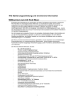
owner's manual GF equalizers
Caution
RISK OF ELECTRIC SHOCK
DO NOT OPEN
:
TO REDUCE THE RISK OF ELECTRIC SHOCK DO NOT REMOVE COVERS
NO USER SERVICEABLE PARTS INSIDE
REFER SERVICING TO QUALIFIED PERSONNEL
THIS SYMBOL IS INTENDED TO ALERT THE USER OF PRESENCE OF
UNINSULATED DANGEROUS VOLTAGE WITHIN THE PRODUCTS
ENCLOSURE THAT MAY BE OF SUFFICIENT MAGNITUDE TO CONSTITUTE RISK OF ELECTRIC SHOCK TO
PERSONS.
THIS SYMBOL IS INTENDED TO ALERT THE USER OF PRESENCE OF IMPORTANT OPERATING AND MAINTENANCE (SERVICING) INSTRUCTIONS IN THE LITERATURE ACCOMPANYING THE APPLIANCE.
Safety Instructions
1. Read Instructions – All the safety and operation instructions should be read before the Zeck Component is operated.
2. Retain Instructions – The operating instruction should be kept for future reference.
3. Heed Warnings – All warnings on the Component and in this operating instructions should be followed.
4. Water and Moisture – The Component should not used near water - for example, near a bathtub, washbowl, kitchen sink,
laundry tub, in a wet basement, or near a swimming pool, etc.
5. Heat – The Component should be situated away from heat sources such as radiators, or other devices which produce heat.
6. Power Cord Protection – Power-supply cords should be routed so that they are not likely to be walked upon or pinched by items
placed upon or against them, paying particular attention to cords at plugs, convenience receptacles, and the point where they
exit the Component.
7. Non-use Periods – The power cord of the Component should be unplugged from the outlet when unused for a long period of
time.
8. Object and Liquid Entry – Care should be taken so that objects do not fall into and liquids are not spilled into the inside of the
Component.
9. Damage Requiring Service – The Component should be serviced only by qualified service personnel when:
• Objects have fallen, or liquid has spilled into the Component; or
• The Component has been exposed to rain; or
• The Component does not appear to operate normally or exhibits a marked change in performance; or
• The Component has been dropped, or its cabinet damaged.
10. Servicing – The user should not attempt to service the Component beyond those means described in this operating manual. All
other servicing should be reffered to qualified service personnel.
11. To prevent electric shock, do not use this polarized plug with an extension cord, receptacle or other outlet unless the blades can
be fully inserted to prevent blade exposure.
12. Grounding or Polarization – Precautions should be taken so that the grounding or polarization means of the Component is not
defeated.
13. Internal Voltage Selectors – Internal line voltage selector switches should only be reset and re-equipped with a proper plug for
alternate voltage by a qualified sevice technician. See an Authorized Zeck Dealer for more information.
WARNING: To reduce the risk of fire or electric shock, do not expose this appliance to rain or moisture.
owner`s manual GF equalizers © 1994 Zeck Audio
3
GF equalizers owner's manual
Zeck Grafischer Equalizer
GF 215 (2 x 15 Band)
GF 230 (2 x 30 Band)
Sehr geehrter Kunde,
Inhalt :
vielen Dank, daß Sie sich für einen Zeck Equalizer entschieden
haben. Dieses professionelle Gerät ist ein äußerst effektives
Instrument zur Klangbeeinflussung für die verschiedensten
Anwendungen, wie Beschallung, Studiotechnik, Stereoanlagen,
Rundfunk und vieles mehr.
1. Kurzübersicht
2. Anschluß des GF Equalizers
3. Bedienelemente
4. Benutzung des GF Equalizers
5. Fehlerbeseitigung
6. Technische Daten
7. Zubehör
Der GF 215 ist ein 2 x 15 Band Equalizer in einem 19" Gehäuse mit zwei Höheneinheiten, der GF 230 ist mit 2 x 30 Bändern
in einem 3 HE Gehäuse ausgestattet. Die Regelfrequenzen
sind nach der ISO Norm festgelegt, wobei die 45mm langen
Fader die Einstellung jeder gewünschten Regelkurve mit größtmöglicher Präzision erlauben. Der Einsatz hochentwickelter
Technologien und modernster Schaltungstechnik, wie lasergetrimmte Bandpaßmodule und Vielfach-Summierungspunkte,
sorgen für ein Minimum an unerwünschten Phasenverschiebungen. Die Filter im GF Equalizer sind als 'Constant Q' Bandpässe ausgelegt, bei denen die Bandbreite über den
ganzen Stellweg des Faders gleich bleibt. Im Gegensatz zum
herkömmlichen Filterdesign mit nichtkonstanter Bandbreite zeigen Zeck GF Equalizer bei Maximalstellung aller Fader nur
eine geringe Welligkeit in der Übertragungskurve. Die Summe
aller dieser hervorragenden technischen Eigenschaften ermöglicht den Einsatz der GF Equalizer innerhalb hochwertiger
Audio-Anlagen.
Bitte lesen Sie die folgenden Hinweise gründlich durch, um sich
mit allen Funktionen Ihres neuen Equalizers vertraut zu
machen.
Ihr Zeck Team
4
owner`s manual GF equalizers © 1994 Zeck Audio
owner's manual GF equalizers
1. Kurzübersicht
Die eingeklammerten Nummern beziehen sich auf die Abbildungen. Es ist nur ein Kanal berücksichtigt, da beide Kanäle
exakt die gleiche Ausstattung besitzen.
Vorderseite
2
25
40
63
100
160
250 400
630
1k
1.6k 2.5k
4k
6.3k 10k
+12
+9
+6
+3
16k
3
3 dB
6 dB
40
63
100 160
250
400
630
1k
1.6k 2.5k
4k
6.3k 10k
0
H
E
A
D
R
O
O
M
12 dB
-10
Signal
0 dB
25
Channel 1
Clip
Gain
+10
16k
Channel 2
Clip
3
2
0
H
E
A
D
R
O
O
M
3 dB
6 dB
12 dB
R
-10
Signal
Gain
GF 215
+10
Constant
Q
2x15 Graphic EQ
-3
-6
-9
- 12
4
25
40
63
100
160
250 400
630
1k
1.6k 2.5k
4k
6.3k 10k
EQ in
4
5
Low cut
16k
25
40
63
100 160
250
400
630
1k
1.6k 2.5k
4k
6.3k 10k
1
Power on
EQ in
Low cut
16k
5
6
6
+12
+9
+6
+3
H
E
A
D
R
O
O
M
Clip
3
3 dB
6 dB
12 dB
Signal
0 dB
0
R
-10
Gain
+10
Constant
Ch 2
-3
-6
-9
- 12
31
40
50
63
80
100
125
160
200 250
315
400
500
630
800
1k 1.25k 1.6k
2k
2.5k 3.15k 4k
5k
6.3k
8k
10k 12.5k 16k
+12
+9
+6
+3
Q
2x30 Graphic EQ
4
25
2
GF 230
EQ in
5
Low cut
20k
H
E
A
D
R
O
O
M
Clip
3
3 dB
6 dB
12 dB
Signal
0 dB
0
2
-10
Gain
+10
Ch 1
-3
-6
-9
- 12
4
5
1
Power on
EQ in
Low cut
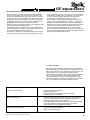
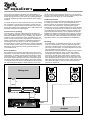
(1) 'Power On' LED, leuchtet rot, wenn Netzspannung eingeschaltet ist
(2) 'Gain' Potentiometer zum Einstellen der Eingangsverstärkung (Empfindlichkeit)
(3) LED Aussteuerungsanzeige, zeigt Pegelreserve bis zum
Übersteuern
(4) 'EQ in' Schalter mit Anzeige-LED zum Aktivieren des Equalizers. Bei nicht-aktiviertem Equalizer sind Ein- und
Ausgänge des Gerätes direkt miteinander verbunden
(5) 'Low Cut' Schalter mit Anzeige-LED, unterdrückt alle
Frequenzen unterhalb 40Hz
(6) Fader zum Anheben und Absenken der einzelnen
Frequenzen
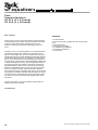
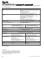
Rückseite
WARNING This apparatus must be earthed.
CAUTION
RISK OF ELECTRIC SHOCK
DO NOT OPEN
!
Output
Channel 2
To reduce the risk of fire or electric shock
do not expose this appliance to rain or moisture
1
Output
1 = Shield
2 = +Life
3 = –Life
CAUTION No user serviceable parts inside.
Refer servicing to qualified personnel.
PUSH
PUSH
PUSH
PUSH
Input
Channel 2
Output
Channel 1
2
2
Input
3
2
3
PUSH
PUSH
PUSH
PUSH
1
1
3
1 = N.C.
2 = +Life
3 = –Life
2
3
1
Input
Channel 1
Power
Fuse
on
off
CAUTION For continued protection against fire hazard
replace only with same type and rating of fuse
13
12
ATTENTION Afin de réduire le risque de feu remplacer
11
AVIS Risque de choc électrique - ne pas ouvrir
uniquement par un fusible de même type et valeur
9
10
7
8
9
10
7
8
(7) XLR-Eingangsbuchse, symmetrisch
(8) Klinken-Eingangsbuchse, symmetrisch
(9) XLR-Ausgangsbuchse, symmetrisch
(10) Klinken-Ausgangsbuchse, symmetrisch
(11) Netzschalter
(12) Sicherungshalter für Netzsicherung
(13) Buchse für Netzanschluß
owner`s manual GF equalizers © 1994 Zeck Audio
5
GF equalizers owner's manual
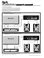
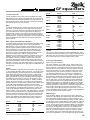
2. Anschluß des GF Equalizers
Die symmetrische Auslegung der Ein- und Ausgangsbuchsen
ermöglicht eine problemlose Verbindung des GF Equalizers mit
allen gängigen Audio-Komponenten. Die nachfolgenden Abbildungen zeigen einige typische Verdrahtungsbeispiele. Die Pinbelegungen der Ein- und Ausgänge sind in den technischen
Daten (Kapitel 6) angegeben.
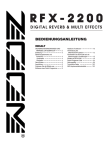
a) Anschluß des GF Equalizers an Mischpulte mit InsertKlinkenbuchsen (Send/Return):
R
In
27
30
33
36
39
42
45
48
Mischpult
Master
Insert
L
R
power
L
24 2118 15 12
Protect
Limit
9
6
3
0
– dB
51 54 5760
∞
Level
ch 1
27
30
33
36
39
42
45
48
24 2118 15 12
Protect
∞
Power
Limit
9
6
3
0
– dB
51 54 5760
Level
AP·1800
2 x 900 W att Ster eo Power Amp
ch 2
Endstufe
L
Out R
Master R
Out
L
'Y'-Kabel: Stereoklinke auf 2 x Monoklinke
25
40
63
100160250400630
1k
1.6k2.5k
4k
6.3k10k16k
3 dB
6 dB
12 dB
40
63
100160250400630
1k
1.6k2.5k4k
6.3k10k16k
0
H
E
A
D
R
O
O
M
Channel 2
Clip
Gain
12 dB
+10
0
H
E
A
D
R
O
O
M
3 dB
6 dB
-10
Signal
0 dB
-3
-6
-9
- 12
25
Channel 1
Clip
+12
+9
+6
+3
R
-10
Signal
Gain
+10
GF 215
Constant
Q
2x15 Graphic EQ
Power on
EQ in
25
40
63
100160250400630
1k
1.6k2.5k
4k
Low cut
EQ in
6.3k10k16k
25
40
63
100160250400630
1k
1.6k2.5k4k
Low cut
6.3k10k16k
GF 215 / GF 230
b) Anschluß des GF Equalizers an Mischpulte ohne InsertKlinkenbuchsen:
L
Input
power
27
30
33
36
39
42
45
48
R
Mischpult
Endstufe
24 2118 15 12
Protect
Limit
9
6
3
0
– dB
51 54 5760
∞
Level
ch 1
27
30
33
36
39
42
45
48
24 2118 15 12
Protect
51 54 5760
Power
Limit
9
6
3
0
– dB
∞
Level
ch 2
AP·1800
2 x 900 W att Ster eo Power Amp
L Output R
L Master R
Out
L Output R
25
40
63
100160250400630
1k
1.6k2.5k
4k
6.3k10k16k
3 dB
6 dB
12 dB
25
H
E
A
D
R
O
O
M
Signal
0 dB
-3
-6
-9
- 12
25
Channel 1
Clip
+12
+9
+6
+3
40
63
100160250400630
1k
1.6k2.5k4k
6.3k10k16k
0
Channel 2
Clip
H
E
A
D
R
O
O
M
3 dB
6 dB
-10
Gain
12 dB
+10
Signal
0
R
-10
Gain
+10
GF 215
Constant
Q
2x15 Graphic EQ
Power on
EQ in
40
63
100160250400630
1k
1.6k2.5k
4k
6.3k10k16k
Low cut
EQ in
25
40
63
100160250400630
1k
1.6k2.5k4k
Low cut
6.3k10k16k
GF 215 / GF 230
Der Anschluß unsymmetrischer Geräte geschieht am einfachsten durch Benutzung von Mono-Klinkensteckern.
6
owner`s manual GF equalizers © 1994 Zeck Audio
owner's manual GF equalizers
3. Bedienelemente
GF 215
Die beiden Kanäle des GF Equalizers sind absolut identisch
und unabhängig voneinander ausgeführt. Die folgenden Erläuterungen beziehen sich daher nur auf einen Kanal.
160 Hz
EQ in
Zum Aktivieren des Equalizers muß sich der 'EQ in' Schalter in
eingerasteter Stellung befinden, was die rote Kontroll-LED
durch Leuchten anzeigt. Ist der Schalter nicht gedrückt, so
befindet sich der Equalizer im Bypass-Zustand (LED dunkel)
und alle Bedienelemente auf der Vorderseite sind deaktiviert.
Im Bypass-Zustand sind alle Ein- und Ausgänge des Gerätes
durch ein Ruhekontakt-Relais direkt miteinander verbunden, so
daß selbst bei Stromausfall keine Unterbrechung des Signalwegs eintritt.
400 Hz
250 Hz
630 Hz
1 kHz
1.6 kH
2.5 kHz
4 kHz
'Gain' Regler und Aussteuerungsanzeige 'Headroom'
Das Eingangssignal des GF Equalizers gelangt zunächst in
eine Vorverstärker-Stufe, wo der Signalpegel mit Hilfe des
'Gain' Reglers verstärkt oder abgeschwächt werden kann. Dieser Regler ist nur bei aktivem Equalizer ('EQ in') aktiv. Befinden
sich alle Fader und der 'Gain' Regler in eingerasteter Mittelstellung, so wird das Signal durch den Equalizer weder verstärkt
noch abgeschwächt und hat denselben Pegel wie bei nichtaktivem Equalizer (Bypass).
Die Aussteuerung des Signals kann mit Hilfe der 'Headroom'
Aussteuerungsanzeige kontrolliert werden. Diese Anzeige mit 5
LEDs zeigt nicht einfach nur den Eingangspegel an, sondern
berücksichtigt auch den jeweils maximalen Signalpegel innerhalb der einzelnen Bandpaß-Filterstufen. Sobald ein Pegel an
einer Stelle im GF Equalizer den maximal zulässigen Spitzenwert überschreitet, leuchtet die 'Clip' LED rot auf. Die Zahlen
neben der 'Headroom' Anzeige zeigen die verbleibende Aussteuerungsreserve bis zum Übersteuern an.
Fader
Jeder Fader ist mit der ihm eigenen Regelfrequenz bezeichnet.
Durch Verstellen eines Faders wird aber nicht nur genau diese
Frequenz beeinflußt, sondern auch Frequenzen innerhalb eines
Bereichs ober- und unterhalb der Mittenfrequenz, genannt
Bandbreite. Diese Bandbreite ist für alle Fader konstant und
wurde so festgelegt, daß sich zwischen dem Bereich zweier
Fader ein optimaler Übergang ohne Einbrüche oder Spitzen im
Frequenzgang ergibt. Die Fader erlauben einen Einstellbereich
von ±12dB Verstärkung bzw. Abschwächung. Als Richtlinie ist
es hilfreich sich zu merken, daß eine Anhebung von 6dB eine
Verdoppelung und eine Abschwächung von 6dB eine Halbierung des Pegels bedeuten. Der Pegel eines Eingangs-Sinussignals von 1kHz und 1Volt könnte somit mit Hilfe des 1kHzFaders zwischen 0.25V und 4Volt eingestellt werden, wobei
0dB 'keine Verstärkung' bedeutet. Die Nennfrequenzen der
Fader sind nach der ISO-Norm festgelegt, wobei der Abstand
zwischen zwei Faderfrequenzen beim GF215 2/3 einer Oktave
entspricht und beim GF230 1/3 einer Oktave. Die folgende
Tabelle zeigt den Zusammenhang zwischen den Nennfrequenzen der einzelnen Fader, den entsprechenden nächstliegenden
Musiknoten und dem Frequenzbereich:
GF 215
GF 230
Note
2 5 Hz
25 Hz
31 Hz
40 Hz
50 Hz
63 Hz
80 Hz
100 Hz
G2
H2
D#1
G1
H1
D#
G
40 Hz
63 Hz
100 Hz
owner`s manual GF equalizers © 1994 Zeck Audio
Bass
6.3 kHz
10 kHz
16 kHz
GF 230
Note
125 Hz
160 Hz
200Hz
250 Hz
315 Hz
H
d#
g
h
d#1
400 Hz
500 Hz
630 Hz
800 Hz
1 kHz
1.25 kHz
g1
h1
d#2
g2
h2
d# 3
1.6 kHz
2 kHz
2.5 kHz
3.15 kHz
4 kHz
5 kHz
g3
h3
d#4
g4
h4
d#5
6.3 kHz
8 kHz
10 kHz
12.5 kHz
16 kHz
20 kHz
g5
h5
d#6
g6
h6
d#7
tiefe Mitten
Mitten
Präsenz
Höhen
Low Cut
Der 'Low cut' Schalter aktiviert ein internes Hochpaßfilter, das
alle Frequenzen unterhalb 40Hz mit einer Flankensteilheit von
18dB/Oktave abschneidet. Hierdurch hat man die Möglichkeit,
unerwünschte Tiefstfrequenzen von Beschallungsanlagen fern
zu halten.
4. Benutzung des GF Equalizers
Was ist ein grafischer Equalizer ?
Die Bezeichnung Equalizer ('Angleicher'), oder kurz EQ, hat
ihren Ursprung in der Forderung, daß eine Beschallungsanlage
einen linearen Frequenzgang aufweisen soll, d.h. alle Frequenzen vom Zuhörer mit der gleichen Lautstärke empfunden werden. Aus verschiedenen Gründen sind Beschallungsanlagen
alleine oft nicht in der Lage, dieser Forderung gerecht zu werden, da sie ohne Korrekturmaßnahmen keinen linearen Frequenzgang aufweisen. Ein graphischer Equalizer stellt ein solches Korrekturinstrument dar, mit dem die Lautstärke einzelner
Frequenzen verstärkt oder abgeschwächt werden kann. Dazu
wird das eintreffende Signal in mehrere (im Falle des GF 215 in
15 und beim GF 230 in 30) Frequenzbänder aufgeteilt, deren
individuelle Lautstärke durch die Fader eingestellt werden
kann. Die Fader zeigen hierbei durch ihre mechanische Stellung den eingestellten Frequenzgang wie bei einer Grafik an,
daher der Ausdruck 'grafischer' Equalizer. Ein Equalizer kann
aber noch mehr als nur Frequenzgänge linearisieren: Auch zur
Feinabstimmung von Instrumentalklängen oder zur Rauschunterdrückung kann der GF Equalizer benutzt werden. Hierzu
werden unten noch weitere Anwendungsbeispiele gegeben.
Einstellen des 'Gain' Reglers
Sowohl der 'Gain' Regler als auch die Fader haben Einfluß auf
die Aussteuerungsanzeige des GF Equalizers, weshalb der
'Gain' Regler erst nach Erreichen einer endgültigen Einstellung
der Fader (s. unten) eingestellt werden sollte. Wird der Equalizer hinter einem Mischpult betrieben, so sollte zunächst auf
diesem das maximal zu erwartende Ausgangssignal eingestellt
werden und der 'Gain' Regler am Equalizer so eingestellt werden, daß dessen 'Headroom' Anzeige ca. 3 bis 6dB Aussteuerungsreserve anzeigt. Nachdem am Equalizer der gewünschte
Frequenzgang eingestellt wurde, wird mit Hilfe des 'Gain' Reg-
7
GF equalizers owner's manual
lers die Aussteuerung erneut so eingestellt, daß bei den lautesten Stellen die 'Clip' Anzeige nicht ständig leuchtet. Für überdurchschnittlich laute Signale sollten einige dB Aussteuerungsreserve gelassen werden, ein gelegentliches kurzes Flackern
der 'Clip' Anzeige führt allerdings nicht sofort zu Verzerrungen.
In einem Tonstudio, wo es auf gehörmäßige Feinabstimmung
von Klängen ankommt, kann es von Vorteil sein, den 'Gain'
Regler so einzustellen, daß der Equalizer bei ein- und ausgeschalteten Zustand die gleiche Lautstärke liefert, da so korrigierter und unkorrigierter Klang am besten miteinander verglichen werden können.
Allgemeine Hinweise zur Equalizer-Einstellung
Als wichtigster Grundsatz sollten Einstellungen am Equalizer
immer langsam und bedacht vorgenommen werden, um ungewollte oder sogar gehörschädigende Rückkopplungen zu vermeiden. Bei Einstellung nach Gehör, sollte man sich klar darüber sein, daß das Ohr sich rasch an eine neue Equalizer-Einstellung anpaßt und diese als neutrale Referenz annimmt. Es
ist daher immer vorteilhaft, von Zeit zu Zeit alte und neue Einstellung zu vergleichen, damit es nicht zu übertriebenen Einstellungen mit unnatürlichem Klangresultat kommt. Anstatt
bestimmte Frequenzen anzuheben, sollte man zunächst versuchen, den gleichen Effekt durch Absenken anderer Frequenzen
zu erreichen, da hierdurch in aller Regel ein natürlicherer Klang
erzielt wird.
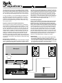
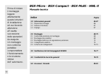
Kompensation von Räumen
Bei Beschallungen wird man selten auf eine akustisch ausgeglichene Umgebung treffen. Meistens werden von dieser, besonders in geschlossenen Räumen, bestimmte Frequenzen bevor-
zugt oder, was viel wahrscheinlicher ist, verschluckt. Um trotzdem eine ausgeglichene Wiedergabe zu erreichen, können mit
einem Equalizer die betroffenen Frequenzen korrigiert werden.
Am einfachsten geschieht dies mit einem Echtzeit-Analyzer,
der direkt anzeigt, welche Frequenzen angehoben oder abgesenkt werden müssen. Zeigt der Analyzer einen flachen Frequenzgang an, so ist der Equalizer richtig auf den betreffenden
Raum abgestimmt. Die folgende Abbildung zeigt, wie ein solcher Echtzeit-Analyzer angeschlossen wird.
Anti-Rückkopplungsfilter
Wenn man die Lautstärke einer Mikrofon-Beschallungsanlage
ständig erhöht, wird mit großer Wahrscheinlichkeit an einem
bestimmten Punkt eine Rückkopplung auftreten. Besonders
Monitor-Lautsprecher sind oft eine Quelle für Rückkopplungen,
da sie meist in relativer Nähe der Mikrofone stehen oder sogar
auf diese gerichtet sind. In der Regel setzt die Rückkopplung
mit einer bestimmten Frequenz ein, die mit Hilfe eines Analyzers oder mit Hilfe eines Musikinstrumentes und der Tabelle
auf Seite 6 bestimmt werden kann. Senkt man am Equalizer
den Fader dieser bestimmten Frequenz ab, so kann die Lautstärke der Gesamtanlage erhöht werden, ohne daß eine Rückkopplung auftritt. Diese Prozedur kann bei Einsetzen der nächsten Rückkopplung wiederholt werden, um einen weiteren
Gewinn an rückkopplungsfreier Lautstärke zu erzielen.
Studiotechnik
- Stereo-Simulation: Hierzu wird ein Mono-Signal gleichzeitig
durch beide Kanäle des Equalizers geschickt, wobei die
Fader so eingestellt werden, daß sie abwechselnd auf +12dB
und -12dB stehen, allerdings bei beiden Kanälen um eine Frequenz versetzt. Die Signale an den beiden Equalizer-Ausgängen ergeben dann den linken und rechten Kanal.
Mischpult
Master
Out
L
R
Input
25
40
63
100160250400630
1k
1.6k2.5k
4k
6.3k10k16k
25
25
Channel 1
Clip
+12
+9
+6
+3
H
E
A
D
R
O
O
M
3 dB
6 dB
12 dB
Signal
0 dB
-3
-6
-9
- 12
40
63
100160250400630
1k
1.6k2.5k4k
6.3k10k16k
0
Channel 2
Clip
H
E
A
D
R
O
O
M
3 dB
6 dB
-10
Gain
12 dB
+10
Signal
0
R
-10
Gain
+10
GF 215
Constant
Q
2x15 Graphic EQ
Power on
EQ in
40
63
100160250400630
1k
1.6k2.5k
4k
Low cut
6.3k10k16k
EQ in
25
40
63
100160250400630
1k
GF 215 / GF 230
1.6k2.5k4k
Low cut
6.3k10k16k
Output
R
L
Input
Meßmikrofon
L
power
27
30
33
36
39
42
45
48
Endstufe
8
24 2118 15 12
Protect
Limit
9
6
3
0
– dB
51 54 5760
∞
Level
ch 1
27
30
33
36
39
42
45
48
24 2118 15 12
Protect
6
3
0
– dB
51 54 5760
∞
Output
Power
Limit
9
Level
ch 2
AP·1800
2 x 900 W att Ster eo Power Amp
R
Analyzer
owner`s manual GF equalizers © 1994 Zeck Audio
owner's manual GF equalizers
- Rauschunterdrückung: Das Rauschen bei Kassettenaufnahmen kann verringert werden, indem bei der Aufnahme alle
Frequenzen oberhalb 6.3kHz angehoben werden und dieselben Frequenzen bei der Wiedergabe um den gleichen Anteil
abgesenkt werden. Das Rauschen von älteren aber bewährten Effektgeräten kann vermindert werden, indem deren Eingangssignal durch Kanal A mit angehobenen Höhen
geschickt wird und das Ausgangssignal vom Effektgerät durch
Kanal B mit verringertem Höhenanteil.
- verbesserter Klang von Effekten: Echo- und Halleffekte klingen durchsichtiger, wenn der Anteil an Bässen und tiefen Mitten in ihrem Eingangssignal verringert wird
- Aufnahme von Gitarren: Verzerrte Gitarrensoli können durch
Anheben der Frequenzen um 4kHz hervorgehoben werden
ohne andere Instrumente zu verdecken. Für druckvolle Rhythmuspassagen empfiehlt sich ein Absenken der Frequenzen
um 1kHz. Diese Einstellung läßt dem Gesang Platz im
Gesamtklang und die Gitarre trotzdem gut hörbar.
- mehr nutzbarer Aufnahmepegel: Akustische Instrumente
besitzen oft ausgeprägte Resonanzspitzen im unteren Frequenzbereich, die bei Aufnahmen schnell zum Übersteuern
führen können. Eine Zurücknahme des gesamten Aufnahmepegels führt zu einer Einbuße an Dynamik und somit zu
einem schlechteren Gesamtklang. Senkt man mit einem
Equalizer die störend hervortretenden Frequenzen gezielt ab,
so kann der Aufnahmepegel zugunsten eines dynamischeren
Gesamtklanges wieder erhöht werden.
5. Fehler-Checkliste
Die folgende Liste enthält die am häufigsten zu erwartenden
Bedienungsfehler und Fehlfunktionen und die Maßnahmen zur
Abhilfe. Bei Auftreten einer Fehlfunktion empfiehlt es sich, die
Liste der Reihe nach durchzugehen bis das Gerät die
gewünschte Funktion wieder zeigt. Sollten alle diese Maßnahmen nicht zum Ziel führen, ist das Gerät mit großer Wahrscheinlichkeit defekt und sollte zum nächstliegenden ZeckHändler zur Reparatur eingeschickt werden. Das Gerät sollte
nur von qualifiziertem Fachpersonal repariert werden.
Fehlfunktion
Abhilfe
'Power On' LED ist dunkel
- 'Power' Netzschalter überprüfen
- Netzkabel überprüfen
- Netzkabel ziehen und Gerätesicherung kontrollieren
- Hauptsicherungen kontrollieren
Kein Ausgangssignal
- Gerät mit Netzschalter ausschalten. Ist immer noch kein Signal
zu hören, liegt das Problem nicht innerhalb des Equalizers.
- Gerät einschalten und Equalizer aktivieren
- das Eingangssignal mit 'Gain' Regler und Aussteuerungsanzeige
überprüfen. Wird ein Signal angezeigt aber nicht hörbar,
Steckverbindungen am Ausgang kontrollieren.
Fader zeigen keine Funktion
- 'Power' Netzschalter überprüfen
- 'EQ on' Schalter überprüfen
owner`s manual GF equalizers © 1994 Zeck Audio
9
GF equalizers owner's manual
6. Technische Daten
GF 215
GF 230
Eingänge
XLR und Klinke, parallelgeschaltet und elektronisch symmetriert
Eingangsimpedanz: 10kOhm
Maximaler Eingangspegel: +22dBm
Anschlußbelegungen: XLR : 1 = frei, 2 = +Signal, 3 = –Signal
Klinke: Spitze = +Signal, Ring = –Signal, Hülse = frei
Ausgänge
XLR und Klinke, parallelgeschaltet
Elektronisch symmetriert und erdfrei (Transformatorsimulation)
Ausgangswiderstand: 51 Ohm pro Klemme
Maximaler Ausgangspegel: +21dBm @ 600 ohms
Anschlußbelegungen:
XLR: 1 = Erde, 2 = +Signal, 3 = –Signal
Klinke: Spitze = +Signal, Ring = –Signal, Hülse = Erde
Frequenzgang
20 Hz - 20 kHz / ±0.5 dB, alle Regler in Mittelstellung, EQ in
Klirrfaktor< 0.01% @
20 Hz - 20 kHz
0.005 % @ 20 Hz - 20 kHz typisch
_______________________________________________________________________________________________________________________________________________________
Rauschen
< – 95 dBm, Regler in Mittelstellung, EQ in
< – 75 dBm, alle Fader am oberen Anschlag
alles @ 22 Hz - 22 kHz, RMS unbew.
Gain-Regler
< – 92 dBm, Regler in Mittelstellung, EQ in
< – 68 dBm, alle Fader am oberen Anschlag
alles @ 22 Hz - 22 kHz, RMS unbew.
–10 dB to +10 dB mit 0 dB Mittelraste
Kanaltrennung
> – 60 dB @ 20 Hz - 20 kHz
Pegelanzeige
5-Stufen LED Anzeige, + 20 dBm Headroom-Referenz
Low Cut Filter
40 Hz / 18 dB Flankensteilheit, maximal flach
Klangsteller
2/3 Oktave, 25 Hz - 16 kHz nach ISO-Norm
Toleranz der Mittenfrequenzen < 5%
Max. Verstärkung/Absenkung ±12 dB (±0.5 dB)
1/3 Oktave, 25 Hz - 20 kHz nach ISO-Norm
Toleranz der Mittenfrequenzen < 5%
Max. Verstärkung/Absenkung ±12 dB
Stromversorgung
Netzspannung: 230 V oder 115 V ac, 10 VA
+10% / –15%
intern änderbar (nur von Fachpersonal)
Netzsicherung: für 230 V T 200 mA / 250 V
für 115 V T 400 mA / 250 V
Netzspannung: 230V oder 115V ac, 15VA
+10% / –15%
intern änderbar (nur von Fachpersonal)
Netzsicherung: für 230 V T 200 mA / 250 V
für 115 V T 400 mA / 250 V
Abmessungen (B x H X T)
482 x 89 x 200 mm, 3 Höheneinheiten
482 x 133 x 200, 4 Höheneinheiten
Gewicht
ca. 5 kg
ca. 7 kg
(±0.5dB)
2 Jahre Garantie
7. Zubehör
Zum Schutz der Frontplatte gegen Beschädigung und versehentliches Verstellen der Bedienelemente ist eine Abdeckplatte
aus getöntem Plexiglas als Zubehör erhältlich. Die Montage
erfolgt mittels der dafür vorgesehenen Löcher in der Frontplatte.
10
owner`s manual GF equalizers © 1994 Zeck Audio
owner's manual GF equalizers
Caution
RISK OF ELECTRIC SHOCK
DO NOT OPEN
:
TO REDUCE THE RISK OF ELECTRIC SHOCK DO NOT REMOVE COVERS
NO USER SERVICEABLE PARTS INSIDE
REFER SERVICING TO QUALIFIED PERSONNEL
THIS SYMBOL IS INTENDED TO ALERT THE USER OF PRESENCE OF
UNINSULATED DANGEROUS VOLTAGE WITHIN THE PRODUCTS
ENCLOSURE THAT MAY BE OF SUFFICIENT MAGNITUDE TO CONSTITUTE RISK OF ELECTRIC SHOCK TO
PERSONS.
THIS SYMBOL IS INTENDED TO ALERT THE USER OF PRESENCE OF IMPORTANT OPERATING AND MAINTENANCE (SERVICING) INSTRUCTIONS IN THE LITERATURE ACCOMPANYING THE APPLIANCE.
Safety Instructions
1. Read Instructions – All the safety and operation instructions should be read before the Zeck Component is operated.
2. Retain Instructions – The operating instruction should be kept for future reference.
3. Heed Warnings – All warnings on the Component and in this operating instructions should be followed.
4. Water and Moisture – The Component should not used near water - for example, near a bathtub, washbowl, kitchen sink,
laundry tub, in a wet basement, or near a swimming pool, etc.
5. Heat – The Component should be situated away from heat sources such as radiators, or other devices which produce heat.
6. Power Cord Protection – Power-supply cords should be routed so that they are not likely to be walked upon or pinched by items
placed upon or against them, paying particular attention to cords at plugs, convenience receptacles, and the point where they
exit the Component.
7. Non-use Periods – The power cord of the Component should be unplugged from the outlet when unused for a long period of
time.
8. Object and Liquid Entry – Care should be taken so that objects do not fall into and liquids are not spilled into the inside of the
Component.
9. Damage Requiring Service – The Component should be serviced only by qualified service personnel when:
• Objects have fallen, or liquid has spilled into the Component; or
• The Component has been exposed to rain; or
• The Component does not appear to operate normally or exhibits a marked change in performance; or
• The Component has been dropped, or its cabinet damaged.
10. Servicing – The user should not attempt to service the Component beyond those means described in this operating manual. All
other servicing should be reffered to qualified service personnel.
11. To prevent electric shock, do not use this polarized plug with an extension cord, receptacle or other outlet unless the blades can
be fully inserted to prevent blade exposure.
12. Grounding or Polarization – Precautions should be taken so that the grounding or polarization means of the Component is not
defeated.
13. Internal Voltage Selectors – Internal line voltage selector switches should only be reset and re-equipped with a proper plug for
alternate voltage by a qualified sevice technician. See an Authorized Zeck Dealer for more information.
WARNING: To reduce the risk of fire or electric shock, do not expose this appliance to rain or moisture.
owner`s manual GF equalizers © 1994 Zeck Audio
11
GF equalizers owner's manual
Zeck
Graphic Equalizer
GF 215 (2 x 15 band)
GF 230 (2 x 30 band)
Dear customer,
thank you very much for purchasing a Zeck graphic equalizer.
This professional unit provides you with a powerful sound shaping tool for all possible audio applications such as PA
systems, recording, home stereo, broadcasting and much
more.
The GF 215 is a 2 x 15 band equalizer in a 19" package using
two rackspace height units, while the GF 230 offers 2 x 30
bands in three height units. The center frequencies have been
specified according to the ISO standard and the high-resolution
45mm faders allow the units to be adjusted to any desired frequency curve with precise accuracy. Making use of sophisticated technology, including laser-trimmed bandpass modules and
multiple summing-point circuitry, phase irregularities between
the frequency bands are reduced to a minimum. All Zeck GF
equalizers feature professional 'Constant Q' filter technology,
where the bandwidth remains the same throughout the entire
boost/cut range of one fader. Unlike most other equalizers,
which utilize the simpler 'variable Q' filter design, the GF equalizers display an extremely low ripple when all faders are at their
maximum position. Outstanding technical specifications allow
the units to be used in conjunction with highest quality audio
equipment.
Contents:
1. Quick reference
2. Connecting the GF equalizer with other audio equipment
3. Control elements
4. Using the GF equalizer
5. Troubleshooting guidelines
6. Technical specifications
7. Accessories
To get the most out of your new equalizer, please study the
following instructions carefully.
The Zeck team
12
owner`s manual GF equalizers © 1994 Zeck Audio
owner's manual GF equalizers
1. Quick reference
The numbers in parentheses refer to the illustrations in this
manual. Only one channel is described, as both channels offer
exactly the same features.
2
25
40
63
100
160
250 400
630
1k
1.6k 2.5k
4k
6.3k 10k
+12
+9
+6
+3
16k
3
3 dB
6 dB
40
63
100 160
250
400
630
1k
1.6k 2.5k
4k
6.3k 10k
0
H
E
A
D
R
O
O
M
12 dB
-10
Signal
0 dB
25
Channel 1
Clip
Gain
+10
16k
Channel 2
Clip
3
2
0
H
E
A
D
R
O
O
M
3 dB
6 dB
12 dB
R
-10
Signal
Gain
GF 215
+10
Constant
Q
2x15 Graphic EQ
-3
-6
-9
- 12
4
25
40
63
100
160
250 400
630
1k
1.6k 2.5k
4k
6.3k 10k
EQ in
4
5
Low cut
16k
25
40
63
100 160
250
400
630
1k
1.6k 2.5k
4k
6.3k 10k
1
Power on
EQ in
Low cut
16k
5
6
6
+12
+9
+6
+3
Clip
3
3 dB
6 dB
12 dB
H
E
A
D
R
O
O
M
Signal
0 dB
0
R
-10
Gain
+10
Constant
Ch 2
-3
-6
-9
- 12
31
40
50
63
80
100
125
160
200 250
315
400
500
630
800
1k 1.25k 1.6k
2k
2.5k 3.15k 4k
5k
6.3k
8k
10k 12.5k 16k
+12
+9
+6
+3
Q
2x30 Graphic EQ
4
25
2
GF 230
EQ in
5
Low cut
20k
Clip
3
3 dB
6 dB
12 dB
H
E
A
D
R
O
O
M
Signal
0 dB
0
2
-10
Gain
+10
Ch 1
-3
-6
-9
- 12
4
1
Power on
EQ in
Low cut
Front panel
(1) 'Power On' - LED, becomes lit when the ac power has been
turned on
(2) 'Gain' - control potentiometer for input sensitivity and overall
gain
(3) LED display for remaining headroom before clipping occurs
(4) 'EQ in' switch with control LED, engages EQ circuitry when
pushed. If this switch is not activated or if the power has been
turned off, inputs and outputs of the equalizer are directly
connected for true bypass operation
(5) 'Low cut' switch with control LED, eliminates all frequencies
below 40Hz
(6) Faders to boost or cut the individual frequency bands
WARNING This apparatus must be earthed.
CAUTION
RISK OF ELECTRIC SHOCK
DO NOT OPEN
!
Output
Channel 2
To reduce the risk of fire or electric shock
do not expose this appliance to rain or moisture
1
Output
1 = Shield
2 = +Life
3 = –Life
CAUTION No user serviceable parts inside.
Refer servicing to qualified personnel.
PUSH
PUSH
PUSH
PUSH
Input
Channel 2
Output
Channel 1
2
2
Input
3
2
3
PUSH
PUSH
PUSH
PUSH
1
1
3
1 = N.C.
2 = +Life
3 = –Life
2
3
1
Input
Channel 1
Power
Fuse
on
off
CAUTION For continued protection against fire hazard
replace only with same type and rating of fuse
13
12
11
ATTENTION Afin de réduire le risque de feu remplacer
AVIS Risque de choc électrique - ne pas ouvrir
uniquement par un fusible de même type et valeur
9
10
7
8
9
10
7
8
Back panel
(7) XLR input, balanced
(8) 1/4" instrument jack input, balanced
(9) XLR output, balanced
(10) 1/4" instrument jack output, balanced
(11) Mains power switch
(12) Fuseholder for mains fuse
(13) Mains power receptacle
owner`s manual GF equalizers © 1994 Zeck Audio
13
GF equalizers owner's manual
2. Connecting the GF equalizer to other audio equipment
Thanks to its balanced inputs and outputs, the GF equalizer
can be connected to any audio equipment with no problems.
Refer to the following illustrations for typical wiring examples.
Pin configurations of the inputs and outputs are specified in the
'Technical specifications' chapter.
a) Connecting mixing consoles with master insert phone jacks
R
power
27
30
33
36
39
42
45
48
Mixing desk
Master
Insert
L
R
L
Master
Out
L
24 2118 15 12
Protect
Limit
9
6
3
0
– dB
51 54 5760
∞
Level
ch 1
27
30
33
36
39
42
45
48
24 2118 15 12
Protect
∞
Power
Limit
9
6
3
0
– dB
51 54 5760
Level
AP·1800
2 x 900 W att Ster eo Power Amp
ch 2
Power amp
L
Out R
R
'Y'-cable: stereo jack to 2 x mono jack
25
40
63
100160250400630
1k
1.6k2.5k
4k
6.3k10k16k
25
Channel 1
Clip
+12
+9
+6
+3
6 dB
40
63
100160250400630
1k
1.6k2.5k4k
6.3k10k16k
0
H
E
A
D
R
O
O
M
3 dB
12 dB
Channel 2
Clip
6 dB
12 dB
+10
Gain
0
H
E
A
D
R
O
O
M
3 dB
-10
Signal
0 dB
-3
-6
-9
- 12
R
-10
Signal
Gain
+10
GF 215
Constant
Q
2x15 Graphic EQ
Power on
EQ in
25
40
63
100160250400630
1k
1.6k2.5k
4k
Low cut
6.3k10k16k
EQ in
25
40
63
100160250400630
1k
1.6k2.5k4k
Low cut
6.3k10k16k
GF 215 / GF 230
b) Connecting mixing consoles without master insert phone jacks
L
Input
power
R
Mixing desk
27
30
33
36
39
42
45
48
Power amp
24 2118 15 12
Protect
Limit
9
6
3
0
– dB
51 54 5760
∞
Level
ch 1
27
30
33
36
39
42
45
48
24 2118 15 12
Protect
∞
Power
Limit
9
6
3
0
– dB
51 54 5760
Level
ch 2
AP·1800
2 x 900 W att Ster eo Power Amp
L Output R
L Master R
Out
L Output R
25
40
63
100160250400630
1k
1.6k2.5k
4k
6.3k10k16k
25
25
Channel 1
Clip
+12
+9
+6
+3
3 dB
6 dB
12 dB
H
E
A
D
R
O
O
M
Signal
0 dB
-3
-6
-9
- 12
40
63
100160250400630
1k
1.6k2.5k4k
6.3k10k16k
0
Channel 2
Clip
H
E
A
D
R
O
O
M
3 dB
6 dB
-10
Gain
12 dB
+10
Signal
0
R
-10
Gain
+10
GF 215
Constant
Q
2x15 Graphic EQ
Power on
EQ in
40
63
100160250400630
1k
1.6k2.5k
4k
6.3k10k16k
Low cut
EQ in
25
40
63
100160250400630
1k
1.6k2.5k4k
Low cut
6.3k10k16k
GF 215 / GF 230
Connecting unbalanced devices to the GF equalizer is done
easiest by using monaural phone jack instrument cables.
14
owner`s manual GF equalizers © 1994 Zeck Audio
owner's manual GF equalizers
GF 215
3. Control elements
The GF equalizer is a true two-channel equalizer with totally
independent circuits. All functional elements are implemented
twice which allows individual equalization of both channels. As
both channels feature exactly the same controls, the following
descriptions refer to only one channel.
EQ in
To activate the EQ function, the 'EQ in' switch must be engaged, which is indicated by its control LED. When the 'EQ in'
switch is not pushed, the unit is in bypass mode (dark LED) and
all control elements on the front panel become inactive. In
bypass mode, the inputs and outputs become directly wired
together by a low-active relay, which also serves as a failsafe
protection device, so that the signal path is not interrupted even
if the unit should become defective or the mains power has
been turned off.
Gain control and 'Headroom' LED meter
The audio signal coming into the GF equalizer is initially going
through a preamplifier stage, where it can be amplified or
attenuated by means of the 'Gain' control knob. This control
affects only the equalized signal and has no effect when the
'EQ in' pushbutton is not activated. With all EQ faders set to
their neutral position and the 'Gain' control at center detent
position, the signal is not amplified or attenuated by the unit
and has the same level in 'EQ on' and bypass mode.
Alterations of the signal level inside the equalizer can be controlled by means of the 'Headroom' LED meter. This 5-step
LED display is not only a simple input level meter, but also
senses the signal levels inside the filter stages. Whenever a
signal level exceeds its maximum value somewhere inside the
electronic circuit, the 'Clip' LED will become lit. The numbers on
the right of the LEDs indicate the gain reserve in dB before clipping will occur.
Faders
Each of the faders is labelled with its assigned center frequency. By changing the fader settings, however, not only the specified center frequency is affected, but also a certain frequency
range below and above this center frequency, called 'bandwidth'. This bandwidth, which is the same for all faders, has
been calculated for the correct overlap between two neighbouring faders to avoid 'holes' or 'humps' in the frequency spectrum. Each fader has a cut/boost range of -12dB to +12dB in
relation to its center position. Even without any knowledge in
decibel arithmetic, one can easily remember that a gain increase of 6 dB means doubling the voltage, whereas as gain
decrease of 6 dB means decreasing it by half. As an example
of this calculation, a single sinewave frequency of 1kHz and
1Volt can be adjusted anywhere between 0.25 Volts and 4
Volts by means of the 1kHz fader, with 0dB meaning no amplification. The center frequencies were selected following the ISO
standard, where the distance between two center frequencies
is 2/3 of an octave on the GF215 and 1/3 of an octave on the
GF230. The following chart specifies the center frequencies,
their corresponding musical notes and frequency domains:
GF 215
25 Hz
40 Hz
63 Hz
100 Hz
GF 230
25 Hz
31 Hz
40 Hz
50 Hz
63 Hz
80 Hz
100 Hz
owner`s manual GF equalizers © 1994 Zeck Audio
Note
G2
H2
D# 1
G1
H1
D#
G
bass
160 Hz
250 Hz
400 Hz
630 Hz
1 kHz
1.6 kH
2.5 kHz
4 kHz
6.3 kHz
10 kHz
16 kHz
GF 230
Note
125 Hz
160 Hz
200Hz
250 Hz
315 Hz
H
d#
g
h
d#1
400 Hz
500 Hz
630 Hz
800 Hz
1 kHz
1.25 kHz
g1
h1
d#2
g2
h2
d# 3
1.6 kHz
2 kHz
2.5 kHz
3.15 kHz
4 kHz
5 kHz
g3
h3
d#4
g4
h4
d#5
6.3 kHz
8 kHz
10 kHz
12.5 kHz
16 kHz
20 kHz
g5
h5
d#6
g6
h6
d#7
low mid
mid
presence
treble
Low cut
The 'Low cut' switch activates an internal highpass filter, which
attenuates all frequencies below 40 Hz with a cutoff slope of 18
dB/octave. This can be useful to keep unwanted ultra-low subsonic frequencies out of a sound reinforcement system.
4. Using the GF Equalizer
What is a graphic equalizer ?
The name equalizer, or just 'EQ' in short, has its origin in the
idea that a sound system should be able to deliver a linear frequency response, so that all frequencies are perceived by the
listeners with the same loudness. For many reasons, however,
sound systems alone are often not able to satisfy this requirement because of their non-linear frequency response, hence
the need to be able to boost or cut the gain of individual frequencies toward an even response. A graphic equalizer provides just that by dividing the incoming audio signal into several
frequency bands (15 bands for the GF 215 and 30 bands for
the GF 230), which can be attenuated or boosted individually.
On a graphic equalizer, these adjustments are done by slide
potentiometers (faders) mounted side by side, giving a perfect
'graphic' visualization of the adjusted equalization curve. But
leveling out frequency responses is not all that an equalizer can
do. It can also be used to fine-tune the sounds of musical
instruments to meet different musical requirements, or even for
noise suppression. More examples of highly useful applications
for the GF equalizers will be given below.
Adjusting gain
Since the fader settings, just as the 'Gain' control, affect the
'headroom' LED display, gain adjustments should be done after
the final equalizer setting has been found (see below). If you
are using the GF equalizer following a mixing console, start off
by setting the mixer's volume faders to their maximum, apply all
channel signals and check the 'Headroom' display. If clipping
occurs, turn the 'Gain' control counterclockwise to compensate
for about 3 to 6dB available headroom. If the display still indicates clipping, the signal level coming into the equalizer is too
high and must be reduced. After the sound system has been
tuned for the desired frequency response, check the 'Headroom' display again and compensate again with the 'Gain' control knob. As a guideline, try to set the gain as high as possible
15
GF equalizers owner's manual
with a loud musical signal, but leave some dB headroom for
unexpected level peaks. However, don't worry if the 'Peak' LED
flickers shortly from time to time at the very loudest passages,
as the GF equalizer still offers some headroom above clipping
indication.
In a studio environment, where precise fine-tuning of sounds by
ear is required, it can also be a good idea to set the gain control, so that the output loudness of the equalizer is the same in
'EQ on' and bypass mode, helping the user to A/B-compare his
equalized sound with the original signal.
General rules for equalizing
In the first place, changing of EQ settings should always be
done carefully and slowly to avoid the danger of annoying if not
hazardous feedback surprises. If you are using your ear as a
reference, bear in mind that the human ear adapts to the new
sound curve and accepts it as a new reference. Therefore, it is
always a good idea to compare the equalized sound with the
original signal from time to time to avoid over-equalization,
which will result in a rather unnatural sound. Instead of boosting
a certain frequency band, first try to achieve the same effect by
attenuating other frequencies, as this generally results in a
more natural sound.
Room equalization
Most acoustical environments, especially rooms, tend to overemphasize, or more likely, 'swallow' certain frequencies for physical reasons. To achieve a linear sound reproduction in spite
of this phenomenon, a graphic equalizer can be used to cut or
boost these suspicious frequencies. First, a real-time analyzer
should be used to detect holes or peaks in the room's frequency response, which can then be compensated for by the equalizer, until the analyzer displays a linear frequency curve. The
sound system is now tuned to the 'house curve' of this particular room. The following illustration shows, how the analyzer and
equalizer have to be set up for room equalization.
Feedback elimination
If the gain of a sound reinforcement system with microphones
is constantly increased, at some point feedback will occur.
Monitor systems are especially sensitive to feedback due to
their position near microphones, especially when angled
towards them. As a rule, feedback starts at one single frequency, which can be determined by an analyzer or with the help of
a musical instrument and the table on page 13. Reducing the
gain of this particular frequency on the equalizer will stop the
feedback and allow the overall gain of the system to be raised,
resulting in a higher sound pressure without feedback. When
the next frequency starts to feed back, this procedure can be
repeated to achieve even more feedback-free amplification.
Recording
- Simulated stereo: a simulated stereo signal can be created
from a monaural signal by routing the signal through both
channels in parallel. Boost and cut alternate bands on channel A and, in reverse order, on channel B and have the channels panned left and right in the mix.
- Noise reduction: hiss on cassette recordings can be reduced
by boosting all frequencies above 6.3 kHz when making
recordings. When playing the tape back, cut the same frequencies on the EQ for the same amount, resulting in less
hiss. Old but proven effect devices can be improved in their
noise behaviour almost the same way: route the input of the
effect device through channel A and the output through channel B. Boost the highs on channel A and cut the same frequencies on channel B.
Mixing desk
Master
Out
L
R
Input
25
40
63
100160250400630
1k
1.6k2.5k
4k
6.3k10k16k
25
25
Channel 1
Clip
+12
+9
+6
+3
H
E
A
D
R
O
O
M
3 dB
6 dB
12 dB
Signal
0 dB
-3
-6
-9
- 12
40
63
100160250400630
1k
1.6k2.5k4k
6.3k10k16k
0
Channel 2
Clip
H
E
A
D
R
O
O
M
3 dB
6 dB
-10
Gain
12 dB
+10
Signal
0
R
-10
Gain
+10
GF 215
Constant
Q
2x15 Graphic EQ
Power on
EQ in
40
63
100160250400630
1k
1.6k2.5k
4k
Low cut
6.3k10k16k
EQ in
25
40
63
100160250400630
1k
GF 215 / GF 230
1.6k2.5k4k
Low cut
6.3k10k16k
Output
R
L
Input
Measuring microphone
L
power
27
30
33
36
39
42
45
48
Power amp
16
24 2118 15 12
Protect
Limit
9
6
3
0
– dB
51 54 5760
∞
Level
ch 1
27
30
33
36
39
42
45
48
24 2118 15 12
Protect
6
3
0
– dB
51 54 5760
∞
Output
Power
Limit
9
Level
ch 2
AP·1800
2 x 900 W att Ster eo Power Amp
R
Analyzer
owner`s manual GF equalizers © 1994 Zeck Audio
owner's manual GF equalizers
- Better sounding effects: reverb and delay effects sound a lot
more transparent, when the bass and low midrange content of
the signal sent to their inputs is reduced.
- Recording guitars: when recording electric guitars, add some
4kHz to distorted solo passages. This will make the lead
stand out without interfering with other instruments in the mix.
For powerful rhythm guitar, cut some of the midrange around
1kHz. This will keep the guitar distinct in the background of
the mix while leaving room for the vocals.
- More headroom: acoustic instruments often have a pronounced resonant peak at a certain frequency somewhere in the
bass or low midrange. This phenomenon can make these
instruments very hard to record as the recording level has to
be adjusted quite low to avoid clipping. With this low recording
volume, all other frequencies will tend to sound weak in comparison. When using the GF equalizer, the disturbing resonant
frequency can be attenuated, which allows for an overall
higher recording level and a much more balanced sound.
5. Troubleshooting
The following list contains the most common malfunctions and
the steps that have to be taken if they should occur. For
quickest success, follow the list in the given order until the desired function is working. If all measures should fail to succeed,
send the unit in to the next authorized Zeck dealer for repair.
Do not try to repair the unit unless you are a qualified service
person.
Problem
Troubleshooting procedures
'Power On' LED does not lit
- check 'Power' switch
- check mains connections
- unplug unit and check mains fuse
- check house fuses
No sound
- turn 'Power' switch off. If there is still no sound, the problem is not
with the GF 215, but somewhere else in the signal chain
- turn 'Power' switch on again and activate 'EQ on' switch
- check incoming signal with gain control and 'Headroom' LEDs. If
there is a signal, check output connections.
Faders do not work
- check 'Power' switch
- check 'EQ' on switch
owner`s manual GF equalizers © 1994 Zeck Audio
17
GF equalizers owner's manual
6. Technical specifications
GF 215
GF 230
Inputs
XLR and 1/4" instrument jack, parallel wired and electronically
balanced
Input Impedance: 10 kohms
Absolute overload level: +22 dBm
Pin configurations: XLR: 1 = n.c., 2 = +signal, 3 = –signal
Phone jack: tip = +signal, ring = –signal, sleeve = n.c.
Outputs
XLR and 1/4" instrument jack, parallel wired
Electronically balanced and floating for transformer simulation
Output Impedance: 51 ohm each terminal
Maximum output level: +21 dBm @ 600 ohms
Pin configurations:
XLR: 1 = earth, 2 = +signal, 3 = –signal
Phone jack: tip = +signal, ring = –signal, sleeve = earth
Frequency response
20 Hz - 20 kHz / ±0.5 dB, all controls flat, EQ in
Total Harmonic Distortion (THD)
< 0.01% @ 20 Hz-20 kHz
0.005 % @ 20 Hz - 20 kHz typically
Noise
< –95 dBm, all controls flat, EQ in
< –75 dBm, all faders in maximum position
both @ 22 Hz - 22 kHz, RMS unweighted
Gain control
< –92 dBm, all controls flat, EQ in
< –68 dBm, all faders in maximum position
both @ 22 Hz - 22 kHz, RMS unweighted
–10 dB to +10 dB with 0 dB center detent position
Channel separation
> –60 dB @ 20 Hz - 20 kHz
Level Indicator
5-step LED meter, +20 dBm headroom reference
Low Cut Filter
40 Hz / 18 dB cutoff slope, maximally flat response
Bandpass filters
2/3 octave, 25 Hz - 16 kHz according to ISO
Center frequency tolerance < 5%
Max. boost / cut ± 12 dB (± 0.5 dB)
1/3 octave, 25 Hz - 20 kHz according to ISO
Center frequency tolerance < 5%
Max. boost / cut ± 12 dB (± 0.5 dB).
Power Requirements
Line voltage: 230 V or 115 V ac, 10 VA
+ 10 % / - 15 %
internally reconnectable
(refer to qualified personnel)
Mains fuse: for 230 V use T160 mA / 250 V
for 115 V use T 320 mA / 250 V
Line voltage: 230 V or 115 V ac, 15 VA
+10% / -15%
internally reconnectable
(refer to qualified personnel)
Mains fuse: for 230 V use T 160 mA / 250 V
for 115 V use T 320 mA / 250 V
Dimensions (w x h X d)
482 x 89 x 200 mm, 2 rackspace height units
482 x 133 x 200, 3 rackspace height units
Weight
5 kg app.
7 kg app.
2 years full warranty
7. Accessories
For protection of the front panel against damage or accidental
moving of the control elements, a transparent Plexiglas front
panel cover plate is available on extra order (GF 215 PC and
GF 230 PC). Attaching is simply done by using the provided
mounting holes in the front panel.
18
owner`s manual GF equalizers © 1994 Zeck Audio
owner's manual GF equalizers
owner`s manual GF equalizers © 1994 Zeck Audio
19
Zeck Audio · Turnhallenweg 6 · D-79183 Waldkirch · Tel.: 0 76 81 / 20 04-0 · Fax: 0 76 81 / 20 04-43