1
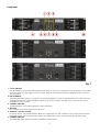
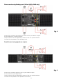
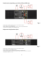
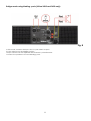
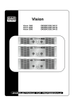
Vision mkII
Vision 1600 ORDERCODE D4151
Vision 2400 ORDERCODE D4152
Vision 3500 ORDERCODE D4153
Congratulations!
You have bought a great, innovative product from DAP Audio.
The DAP Audio Vision series brings excitement to any venue. Whether you want simple plug-&-play action
or a sophisticated show, this product provides the effect you need.
You can rely on DAP Audio, for more excellent audio products.
We design and manufacture professional audio equipment for the entertainment industry.
New products are being launched regularly. We work hard to keep you, our customer, satisfied.
For more information: [email protected]
You can get some of the best quality, best priced products on the market from DAP Audio.
So next time, turn to DAP Audio for more great audio equipment.
Always get the best -- with DAP Audio !
Thank you!
DAP Audio
Dap Audio Vision 1600, 2400, 3500 Product Guide
Warning.................................................................................…...……………..…………………………….………..….. 2
Safety-instructions………………………………………………………………………………………………………… 2
Operating Determinations.……………………………………………………………………………………………… 3
Description...............................................................................…...………………………………………….………..….
Features.................................................................................................................................................................
Overview Front panel...........................................................................................................................................
Overview Back panel...........................................................................................................................................
4
4
5
6
Operation................................................................................................................................................................... 8
Connection Cables..............................….......................................………..………….…….………….………………. 12
Maintenance...................................................................................………..………….…….………………………...... 14
Replacing the Fuse......................................................................…………………….………………………………14
Troubleshooting............................................................................………………….………………….………………... 14
Product Specifications.................................................................……………….…….………………………………... 15
1
WARNING
CAUTION!
Keep this system away from rain and moisture!
FOR YOUR OWN SAFETY, PLEASE READ THIS USER MANUAL CAREFULLY
BEFORE YOUR INITIAL START-UP!
SAFETY INSTRUCTIONS
Every person involved with the installation, operation and maintenance of this system have to:
be qualified
follow the instructions of this manual
CAUTION! Be careful with your operations.
With a dangerous voltage you can suffer
a dangerous electric shock when touching the wires!
Before you initial start-up, please make sure that there is no damage caused by transportation. Should
there be any, consult your dealer and do not use the system.
To maintain perfect condition and to ensure a safe operation, it is absolutely necessary for the user to
follow the safety instructions and warning notes written in this manual.
Please consider that damages caused by manual modifications to the system are not subject to
warranty.
This system contains no user-serviceable parts. Refer servicing to qualified technicians only.
IMPORTANT:
The manufacturer will not accept liability for any resulting damages caused by the nonobservance of this manual or any unauthorized modification to the system.
Never let the power-cord come into contact with other cables! Handle the power-cord and all
connections with the mains with particular caution!
Never remove warning or informative labels from the unit.
Never use anything to cover the ground contact.
Do not insert objects into air vents.
Do not connect this system to a dimmer pack.
Do not switch the system on and off in short intervals, as this would reduce the system’s life.
Do not open the device and do not modify the device.
Do not open this device. Risk: hazardous radiation exposure.
Only use system indoor, avoid contact with water or other liquids.
Avoid flames and do not put close to flammable liquids or gases.
Always disconnect power from the mains, when system is not used. Only handle the power-cord
by the plug. Never pull out the plug by tugging the power-cord.
Make sure you don’t use the wrong kind of cables or defective cables.
Make sure that the signals into the mixer are balanced, otherwise hum could be created.
Make sure you use DI boxes to balance unbalanced signals; all incoming signals should be clear.
Make sure that the available voltage is not higher than stated on the rear panel.
Make sure that the power-cord is never crimped or damaged. Check the system and the powercord from time to time.
Make sure that the amplifier is turned down, before turning the power on or off. So you can avoid
supersonic frequencies, which could damage your speakers.
Don't put your equipment next to TV, radio, etc., because of interference or distortion.
If you connect other parts of the system, be careful of ground loops.
The best way to avoid ground loops is connecting the electrical system ground to one central
point ("star" system). In this case the mixer can act as a central point.
Before changing the ground, always turn off your amplifier.
2
Please read this manual carefully and keep it for future reference. Remember that the amplifier
has a better value on the market, if you save the carton and all packing materials.
Always operate the unit with the AC ground wire connected to the electrical system ground.
Connecting amplifier outputs to oscilloscopes or other test equipment, while the amplifier is in
bridged mode, may damage both the amplifier and test equipment.
Do not drive the inputs with a signal level bigger, than required to drive the equipment to full
output.
In system setup, the amplifier's output power must be 50%-100% more than the loaded
loudspeakers rated power.
Please turn off the power switch, when changing the power cord or signal cable, or select the
input mode switch.
In typical use, please set the volume at 0dB position.
Sometimes, when you want to send one signal to more than one amplifier, you should use a signal
distributor.
If your Dap Audio device fails to work properly, discontinue use immediately. Pack the unit
securely (preferably in the original packing material), and return it to your Dap Audio dealer for
service.
Allow time to cool down, before cleaning or servicing.
For replacement use fuses of same type and rating only.
Prevent distortion! Make sure that all components connected to the DSA have sufficient power
ratings. Otherwise distortion will be generated because the components are operated at their
limits.
Avoid ground loops! Always be sure to connect the power amps and the mixing console to the
same electrical circuit to ensure the same phase!
If system is dropped or struck, disconnect mains power supply immediately. Have a qualified
engineer inspect for safety before operating.
If the system has been exposed to drastic temperature fluctuation (e.g. after transportation), do
not switch it on immediately. The arising condensation water might damage your system. Leave
the system switched off until it has reached room temperature.
This device falls under protection class I. Therefore it is essential to connect the yellow/green
conductor to earth.
Repairs, servicing and electric connection must be carried out by a qualified technician.
WARRANTY: Till one year after date of purchase.
OPERATING DETERMINATIONS
If this system is operated in any other way, than the one described in this manual, the product may suffer
damages and the warranty becomes void. Any other operation may lead to dangers like short-circuit,
burns, electric shock, etc. You endanger your own safety and the safety of others!
Connection with the mains
Connect the device to the mains with the power-plug.
Always pay attention, that the right color cable is connected to the right place.
International
EU Cable
UK Cable
US Cable
Pin
L
BROWN
RED
YELLOW/COPPER
FASE
N
BLUE
BLACK
SILVER
NUL
YELLOW/GREEN
GREEN
GREEN
EARTH
Make sure that the device is always connected properly to the earth!
Improper installation can cause serious damage to people and property!
3
Description of the device
Features
The Vision 1600, 2400 and 3500 are professional high-end amplifiers :
Vision 1600
• 2x Channel in and Link out
• 2x Speakon out
• Built-in Clip Limiter
• Switch-able entrance sensitivity: 0.775V, 1V and 1.4V
• Bridge, parallel or stereo mode
• 30 Hz Hi-pass filter, -3 dB, 18 dB/oct.
• Ground-selector
• Back to front airflow
• Amplifier has softstart and separate standby power. In case of temporary power failure, the amplifier
has to be restarted by pushing the ON/OFF switch again. On and off switching eventually happens
with relay.
Vision 2400
• This amplifier is primarily secured on 15A
• 2x Channel in and Link out
• 2x Speakon out and 2x binding- post out
• Selectable Clip Limiter
• Selectable input sensitivity: 0.775V, 1V and 1.4V
• Bridge, parallel or stereo mode
• 30 Hz Hi-pass filter, -3 dB, 18 dB/oct.
• Ground-selector
• Selectable crossover, Low-pass, 150 Hz, 18 dB/oct.
• Back to front airflow
• Amplifier has softstart and separate standby power. In case of temporary power failure, the amplifier
has to be restarted by pushing the ON/OFF switch again. On and off switching eventually happens with
relay.
Vision 3500
• This amplifier is primarily secured on 18A
• 2x Channel in and Link out
• 2x Speakon out and 2x binding- post out
• Selectable Clip Limiter
• Selectable input sensitivity: 0.775V, 1V and 1.4V
• Bridge, parallel or stereo mode
• 30 Hz Hi-pass filter, -3 dB, 18 dB/oct.
• Ground-selector
• Selectable crossover, Low-pass, 150 Hz, 18 dB/oct.
• Back to front airflow
• Amplifier has softstart and separate standby power. In case of temporary power failure, the amplifier
has to be restarted by pushing the ON/OFF switch again. On and off switching eventually happens
with relay.
4
Frontpanel
Fig. 1
1. "CLIP" Indicator
Any illumination of the clip LED indicates distortion. In this case, check the output signal of your mixer
and turn down the input gain control. Please keep in mind that the power amplifier cannot correct
any distortion.
2. LED "STAND BY"
This indicator lights when you switch your power amplifier on and stays illuminated for a few seconds
(during this time the power amplifier makes an auto-test). When the LED dims, it means the power
amplifier is ready to work.
3. "SIGNAL" Indicator
The illumination of the LED indicates a safe operation.
4. Air vents
Don't obstruct or insert objects into air vents.
5. Channel 1 Volume Control
In stereo mode, this potentiometer allows the adjustment of the channel 1 input level. (left channel ).
In Bridge mode, this potentiometer allows the adjustment of the two channels at the same time.
6. "POWER" Indicator
This indicator lights when the power amplifier is switched on.
5
7. Power Switch
Use this switch to switch your power amplifier on.
8. "PROTECTION" Indicator
When this indicator lights, the power amplifier is in protection mode. Switch off the device and find
out what the problem is. The power amplifier is protected against overheat, overload, short circuit,
DC, soft-start.
9. Channel 2 Volume Control
In stereo mode, this potentiometer allows the adjustment of the channel 2 input level. (Right channel)
In bridge mode, this potentiometer is disabled.
10. Handles
Handles are used for easy transportation.
Backpanel:
Fig.2
11. Channel 1 XLR Input
This XLR input is a balanced input. Connect this input to the left output of your mixer.
12. Channel 1 Link Socket
This balanced socket is used to link another amplifier.
13. Input Sensitivity Selector
This selector allows you, to select the input sensitivity: 0.775V, 1.0V or 1.4V.
14. Bridge LED
This LED lights if the amplifier is in bridge mode.
6
15. Operation Mode Selector
This switch is used to select the operating mode of the power amplifier:
Stereo Mode: 2 inputs (channel 1 and 2) and 2 outputs are used.
Parallel Mode: 1 input (channel 1) and 2 outputs are used.
Bridge Mode: 1 input (channel 1) and 1 output is used.
16. Channel 1 Speakon Output
Connect this Speakon output to a speaker. Use connections +1and -1 (except in bridge mode where
the connections are +1and +2).
17. Air Entrance
This part is the air entrance. Don't obstruct it.
18. Channel 2 XLR Input
This XLR input is a balanced input. Connect this input to the right output of your mixer.
19. Channel 2 Link Socket
This balanced socket is used to link another amplifier.
20. High Pass Filter Selector (Vision 1600 only)
This switch is used to cut low frequency under 30Hz. Put the switch in the "ON" position when you want
to use the power amplifier with one (or several) subwoofer speakers.
21. Ground Selector
If you experience hum or noise in your speaker, put the selector in "ON" position.
22. Channel 2 Speakon Output
Connect this Speakon output to a speaker. Use connections +1 and -1.
23. IEC Power Connector with integrated fuse holder (Vision 1600 only)
24. High Pass Filter Selector (Vision 2400 and Vision 3500 only)
This switch is used to cut low frequency under 30Hz. Put the switch in the "ON" position when you want
to use the power amplifier with one (or several) subwoofer speakers.
25. Limiter ON/Off (Vision 2400 and Vision 3500 only)
26. 150 Low Pass filter (Vision 2400 and Vision 3500 only)
For use in crossover applications.
27. Binding- post channel 1 (Vision 2400 and Vision 3500 only)
Can be used instead of the Speakon connectors.
28. Binding- post channel 2 (Vision 2400 and Vision 3500 only)
Can be used instead of the Speakon connectors.
29. AC Cord (Vision 2400 and 3500 only)
Plug this cord into the power supply socket. (Before using the power amplifier, check if the power
supply is 240V).
30. Fuse (Vision 2400 and 3500 only)
The fuse is used to protect your amplifier from different kinds of AC problems. If the power amplifier is
"on" and nothing lights, please check the fuse compartment. If a fuse is broken, please be sure to use
a fuse of the same type and specification
7
Operation
Installation
Remove all packing materials from the Vision. Check that all foam and plastic padding is removed.
Screw the equipment into a 19" rack. Connect all cables.
Always disconnect from electric mains power supply before cleaning or servicing.
Damages caused by non-observance are not subject to warranty.
Set Up and Operation
Before plugging the unit in, always make sure that the power supply matches the product specification
voltage. Do not attempt to operate a 120V specification product on 240V power, or vice versa.
Install this device on a flat surface, not bending or curved.
Do not supply power before all components of the system are set up and connected properly.
Mode Selection
The three-position, recessed Mode Select switch (located on the rear panel) configures the amplifier for
either Stereo. Parallel or Bridged Mono Mode. Amplifiers are factory-configured for Stereo Mode.
Stereo mode using Speakon outputs:
Fig. 3
In this mode, connect the 2 inputs CH1 and CH2 to your mixer's outputs.
Put the selector in stereo position.
Output volume can be adjusted by means of the two potentiometers.
Connect the 2 speakers to the Speakon connectors.
8
Stereo mode using Binding posts (Vision 2400 & 3600 only) :
Fig. 4
In this mode, connect the 2 inputs CH1 and CH2 to your mixer's outputs.
Put the selector to in stereo position.
Output volume can be adjusted by means of the two potentiometers.
Connect the 2 speakers to the binding- posts.
Parallel mode using Speakon outputs:
Fig. 5
In this mode, connect the input CH1 to your mixer's outputs.
Put the selector in parallel position.
Output volume can be adjusted by means of the two potentiometers.
Connect the 2 speakers to the Speakon connectors.
9
Parallel mode using binding- posts (Vision 2400 and 3600 only) :
Fig. 6
In this mode, connect the input CH1 to your mixer's outputs.
Put the selector in parallel position.
Output volume can be adjusted by means of the two potentiometers.
Connect the 2 speakers to the binding- posts.
Bridge mode using Speakon outputs:
Fig. 7
In this mode, connect the input CH1 to your mixer's outputs.
Put the selector on the bridge position.
Output volume can be adjusted with channel 1 potentiometer.
Connect the speaker to the CH1 Speakon output. Make sure you use a proper
connection cable (1+ & 2+).
10
Bridge mode using binding- posts (Vision 2400 and 3600 only):
Fig. 8
In this mode, connect the input CH1 to your mixer's outputs.
Put the selector on the bridge position.
Output volume can be adjusted with channel 1 potentiometer.
Connect the speaker to the red binding- posts.
11
Connection Cables
Take care of the connector cables, always holding them by the connectors and avoiding knots and
twists when coiling them: This gives the advantage of increasing their life and reliability, which is always to
your advantage.
Periodically check that your cables are in good condition, that they are correctly wired and that all their
contacts are in good condition: a great number of problems (faulty contacts, ground hum, discharges,
etc.) are caused entirely by using unsuitable or faulty cables.
Headphones plug
Unbalanced mono 1/4” jack plug
12
Balanced mono 1/4” jack
Compensation of interference with balanced connections
13
Maintenance
The Vision requires almost no maintenance. However, you should keep the unit clean. Disconnect the
mains power supply, and then wipe the cover with a damp cloth. Do not immerse in liquid.
Keep connections clean. Disconnect electric power, and then wipe the audio connections with a damp
cloth. Make sure connections are thoroughly dry before linking equipment or supplying electric power.
Replacing a Fuse
Power surges, short-circuit or inappropriate electrical power supply may cause a fuse to burn out. If the
fuse burns out, the product will not function whatsoever. If this happens, follow the directions below to do
so.
1. Unplug the unit from electric power source.
2. In case of a Vision 1600:
Insert a flat-head screwdriver into a slot in the fuse cover. Gently pry up the fuse cover. The fuse will
come out.
In case of a Vision 2400/ 3500:
Insert a screwdriver into the slot in the fuse cover. Turn the screwdriver to the left, at the same
time gently push a bit (Turn and Push). The fuse will come out.
3. Remove the broken fuse. If brown or unclear, it is burned out.
4. Insert the replacement fuse into the holder where the old fuse was. Reinsert the fuse cover.
Be sure to use a fuse of the same type and specification. See the product specification label
for details.
Troubleshooting
Dap Audio Vision 1600, 2400 and 3500
This troubleshooting guide is meant to help solve simple problems.
If a problem occurs, carry out the steps below in sequence until a solution is found. Once the unit
operates properly, do not carry out following steps.
If the amplifier does not operate properly, refer servicing to a technician.
1. If you experience low output or no output at all, unplug immediately.
2. Check the fuse, power from the wall, all cables etc.
3. If all of the above appears to be O.K., plug the unit in again.
4. If you are unable to determine the cause of the problem, do not open the amplifier, as this
may damage the unit and the warranty will become void.
5. Return the amplifier to your Dap Audio dealer.
14
Product Specifications
MODE
VISION 1600
Stereo Mode
Bridge Mode
VISION 2400
VISION 3500
8Ω
2x 620Wrms
2x840Wrms
2x1200Wrms
4Ω
2x 1050Wrms
2x1360Wrms
2x1920Wrms
2Ω
2x 1500Wrms
2x1920Wrms
2x2850Wrms
8Ω
2100Wrms
2720Wrms
3840Wrms
4Ω
3000Wrms
3840Wrms
5700Wrms
Frequency response
8Hz-50kHz(-1dB)
15Hz-35kHz(-1dB)
THD+N
<0.03%
<0.03%
<0.03%
Slew rate
30V/μs
40V/μs
44V/μs
400
430
400
Damping factor at 8Ω
S/N ratio
>103dB (A-weighed)
Input sensitivity
0.775V, 1V, 1.4V
Max Input Voltage
+22dBu
Input Imp.
20kΩ Balanced
10kΩ Unbalanced
Subsonic Filter (selectable)
30Hz, 18dB/Oct
Lowpass Filter (Selectable)
Protection
none
150Hz, 18dB/Oct
Fixed limiter
Selectable limiter
Short circuit
Input overload
Output overload
DC voltage
High temperature
Soft start
Output modes (selectable)
Stereo/parallel/bridge
Cooling
Multi speed fan
Airflow
Back to front
Input/ link connector
XLR/XLR
Output connector
2x speakon
Groundlift switch
yes
yes
AC 240V-50Hz
Main fuse
Power consumption(full power 4Ω)
Dimensions (WxHxD)
XLR/XLR
2x speakon/2x bindingpost
yes
Power supply
Gross weight
XLR/XLR
15AT 5x20
15AT 6x32
18AT 6x32
3000W
3430W
4800W
24.62kg
33.8kg
36.06kg
483x89x455mm
483x132x455mm
Design and product specifications are subject to change without prior notice.
Website: www.Dap-audio.info
Email: [email protected]
15
2008 Dap Audio.