1
INSTALLER / CONSUMER
SAFETY INFORMATION
Please read this manual before
installing and using appliance.
WARNING: If the information in this
manual is not followed exactly, a
fire or explosion may result causing
property damage, personal injury or
loss of life.
—Do not store or use gasoline or
other flammable vapors and
liquids in the vicinity of this or
any other appliance.
—WHAT TO DO IF YOU SMELL GAS
• Do not try to light any
appliance.
• Do not touch any electrical
switch; do not use any phone
in your building.
• Immediately call your gas
suppler from a neighbor’s
phone. Follow the gas
suppler’s instructions.
• If you cannot reach your gas
supplier, call the fire
department.
Installation and service must be
performed by a qualified installer,
service agency or the gas supplier.
This is an unvented gas-fired heater.
It uses air (Oxygen) from the room
in which it is installed. Provisions for
adequate combust0ion and
ventilation air must be provided.
Refer to Page 7.
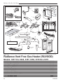
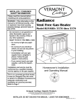
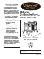
Radiance
Vent Free Gas Heater
Model RUVSOD: 3237 thru 3244,
3357, 3358, 3370 thru 3379
RAD
IAN
CE
Homeowner’s Installation
and Operating Manual
4555
RadianceDESIGN
UVSOD
cover
7/24/01 djt
CE
RTIFI E D
INSTALLER: Leave this manual with the appliance.
CONSUMER: Retain this manual for future reference.
20004555 4/07 Rev. 17
Radiance Vent-Free Gas Heater
Table Of Contents
PLEASE READ THE INSTALLATION & OPERATING INSTRUCTIONS BEFORE USING APPLIANCE.
Thank you and congratulations on your purchase of a Vermont Castings stove.
IMPORTANT: Read all instructions and warnings carefully before starting installation. Failure to follow these
instructions may result in a possible fire hazard and will void the warranty.
Installation and Operating Instructions ...................................................................................... 3
Stove Dimensions ............................................................................................................... 4
Clearance Requirements..................................................................................................... 5
Hearth Requirements .......................................................................................................... 5
Gas Specifications............................................................................................................... 6
Gas Inlet and Manifold Pressures ....................................................................................... 6
High Elevations ................................................................................................................... 6
Odor During Operation ........................................................................................................ 6
Vent Free Features.............................................................................................................. 7
Fresh Air Requirements....................................................................................................... 7
Assembly Procedures
Tools Required/Hardware Bag Contents ............................................................................. 9
Unpacking the Radiance ..................................................................................................... 9
Remove the Front, Screen and Logs .................................................................................. 9
Assemble Legs .................................................................................................................. 10
Install Optional Fan ........................................................................................................... 10
Install ON/OFF Switch ....................................................................................................... 12
Thermostat Connection (Optional) .................................................................................... 12
Glass & Catalyst Installation.............................................................................................. 13
Connect the Gas Supply Line............................................................................................ 14
Install Log Set.................................................................................................................... 14
Complete the Installation ................................................................................................... 15
Operation
Your First Fire .................................................................................................................... 16
Pilot and Burner Inspection ............................................................................................... 16
Flame & Temperature Adjustment ..................................................................................... 16
Flame Characteristics........................................................................................................ 16
Lighting Instructions .......................................................................................................... 17
Troubleshooting ................................................................................................................. 18
Maintenance
Firebox Cleaning and Inspection ....................................................................................... 20
Cleaning Procedure........................................................................................................... 20
Glass Replacement ........................................................................................................... 20
Care of Cast Iron ............................................................................................................... 20
Catalytic Combustor .......................................................................................................... 21
Replacement Parts ...................................................................................................................... 22
Optional Accessories ................................................................................................................. 24
Warranty ....................................................................................................................................... 25
Proposition 65 Warning: Fuels used in gas, woodburning or oil fired appliances, and the products of combustion of such fuels, contain chemicals known to the State
of California to cause cancer, birth defects and other
reproductive harm.
California Health & Safety Code Sec. 25249.6
2
20004555
Radiance Vent-Free Gas Heater
Installation & Operating Instructions
In order to ensure safe and effective installation, this unit
must be installed only by a qualified agency, individual, firm,
corporation or company that is experienced in the installation, repair and servicing of this type of appliance and is
familiar with the building codes and installation techniques
appropriate in your area. Contact your hearth products
dealer or local gas supplier for the name of a qualified service person.
In the Commonwealth of Massachusetts, all gas fittings and
installation of this heater shall only be done by a licensed
gas fitter or licensed plumber.
IMPORTANT: Read this owner’s manual carefully and
completely before trying to assemble, operate, or service this heater. Improper use of this heater can cause
serious injury or death from burns, fire, explosion, electrical shock, and carbon monoxide poisoning. Failure
to follow instructions may result in property damage,
bodily injury or loss of life. This manual contains important user information. Keep this manual with the heater
after installation is complete.
FOR SAFE INSTALLATION AND OPERATION,
PLEASE NOTE THE FOLLOWING:
1. Use only Natural Gas with RUVSODRN. Use only
Propane with RUVSODRP. Do not use any other
fuels.
2. Install only in accordance with the National Fuel
Gas Code, ANSIZ223.1/NFPA54-latest edition. (Exception: Do not derate this appliance for altitude.
This appliance has been tested and listed for use
in altitudes up to 10,000 feet.)
3. Use only the installation instructions provided by
the manufacturer for this appliance. Installation
and repair should be done by a qualified installer,
preferably NFI or WETT (Canada) certified. The
appliance should be inspected before use and at
least annually by a professional service person.
More frequent cleaning may be required due to
excessive lint from carpeting, bedding material,
etc. It is imperative that control compartments,
burners and circulating air passageways of the appliance be kept clean.
4. WARNING: Any change to this heater or its controls can be dangerous. DO NOT make modifications to any heater or associated parts.
5. DO NOT install this heater in a bedroom or bathroom.
6. Due to high surface temperatures, DO NOT install
this heater
• in a recreational vehicle,
• where curtains, furniture, clothing or other
flammable objects are less than 36 inches from
the front, top or sides of the heater,
• in high traffic areas,
• in windy or drafty areas.
20004555
CARBON MONOXIDE POISONING
MAY LEAD TO DEATH!
Carbon Monoxide Poisoning: Early signs of carbon
monoxide poisoning resemble the flu, with headaches,
dizziness, or nausea. If you have these signs, the heater
may not be working properly. Get fresh air at once! Have
the heater serviced. Some people are more affected by
carbon monoxide than others. These include pregnant
women, people with heart or lung disease or anemia,
those under the influence of alcohol, and those at high
altitudes.
7. DO NOT place clothing or other flammable material on or near the appliance.
8. DO NOT obstruct the top grille at all. Doing so will
cause high levels of carbon monoxide that will
lead to death.
9. This heater needs fresh, outside air ventilation to
operate properly. See Fresh Air Requirements on
Pages 7 and 8.
10. If heater shuts off, heater may not have enough
fresh air ventilation. Provide more fresh air. If
heater keeps shutting off, refer to Troubleshooting.
11. DO NOT operate this heater
• where flammable liquids or vapors are used
or stored
• under dusty conditions.
12. The heater becomes very hot when operating.
Alert children and adults to stay away from hot
surfaces to avoid burns or clothing ignition. The
heater will remain hot for a time after shutdown.
Allow surface to cool before touching.
13. Carefully supervise young children when they are
in the room with the heater.
14. Do not use the heater if any part has been exposed to or under water. Immediately call a qualified service technician to inspect the room heater
and to replace any part of the control system and
any gas control which has been under water.
15. DO NOT operate the heater if any log is broken or
damaged.
16. Turn heater off and let cool before servicing. Only
a qualified service person should service and
repair heater.
17. DO NOT operate this appliance with the safety
screen removed. If the safety screen is removed
from the appliance for service or cleaning, it must
be replaced before operating the heater.
NOTE: If any of the original wire as supplied with the appliance must be replaced, it must be replaced with a wire
of at least 105°F temperature rating.
3
Radiance Vent-Free Gas Heater
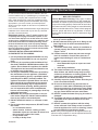
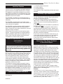
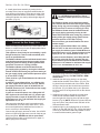
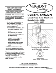
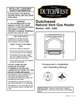
Radiance Vent Free Gas Heater Dimensions
29���"
(756mm)
RADIANCE
28���"
(717mm)
6���"
(165mm)
31"
(787mm)
4
11"
(279mm)
18���"
(465mm)
Drawing Not to Scale
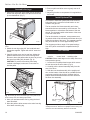
Fig. 1 Radiance Vent Free dimensions.
Supply Inlet
4555
4555
RUVSOD specs
7/01
20004555
Radiance Vent-Free Gas Heater
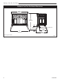
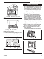
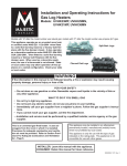
Clearance Requirements
A
Minimum Clearances to
Combustible Materials
B
C
Maintain clearance, (empty space), between combustible materials and the heater as specified below.
V
D
W
A
B
Wall
E
X
Y
Z
ST694
ST101
A: To Side Wall / Trim*........................... 4” (102 mm)
ST101
B: To Rear Wall .....................................
4” (102 mm)
Min. Freestanding Clrnc
djt
4/15/99
Alcove Clearances
B
B
A
C
Ref.
A
B
C
D
E
Mantel
Shelf Depth
7¹⁄₂” (190 mm)
6” (152 mm)
4¹⁄₂” (114 mm)
3” (75 mm)
1¹⁄₂” (38 mm)
Ref.
V
W
X
Y
Z
Mantel from
Stove Top
16” (406 mm)
14¹⁄₂” (368 mm)
13” (330 mm)
11¹⁄₂” (292 mm)
10” (254 mm)
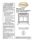
Fig. 3 Minimum mantel clearance.
D
FP599b
Hearth
JUV Requirements
ST103a
A:
B:
C:
D:
Maximum Alcove Depth .............. 24” (610 mm)
To Side Wall ..................................
4” (102 mm)
ST103a
To Rear Wall .................................
4” (102 mm)
Min. Clrnc
11/12/99 djt
To Ceiling ..................................
60” (1524 mm)
Fig. 2 Minimum wall clearances.
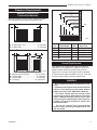
20004555
stove mantel
heights
The Radiance Unvented
heater
must be installed on
9/21/00 djt
rigid flooring. If the appliance is installed on any combustible surface other than wood flooring, such as
carpet or tile, a metal or wood panel must be installed
to extend the full length and width of the unit. There are
no other hearth or floor protection requirements.
WARNING
• Do not install this heater in a bathroom or bedroom.
• Installation of this heater must conform with local
codes or, in the absence of local codes, with the
National Fuel Gas Code, ANSI Z223.1/NFPA 54.
• This heater creates warm air currents. These
currents move heat to wall surfaces next to the
heater. Installing the heater next to vinyl or cloth
wall coverings or operating the heater where impurities in the air such as tobacco smoke exist,
may discolor walls.
• Do not use a blower insert, heat exchanger
insert or other accessory not approved for use
with this heater.
5
Radiance Vent-Free Gas Heater
High Elevations
Gas Specifications
Model
RUVSODRN
RUVSODRP
RUVSODRP
w/Catalyst
Max.
Gas
Input
Fuel Control BTU/h
Nat. Millivolt 35,000
Prop Millivolt 35,000
Firebox weight / shipping
Min.
Input
BTU/h
26,000
Air
Shutter
Setting
Fully
Closed
1” Open
26,000 No air
shutter
(remove)
175 lbs.
Gas Inlet and Manifold Pressures
Inlet Minimum
Natural
5.5” w.c.
LP (Propane)
11” w.c.
Inlet Maximum
14” w.c.
14” w.c.
Manifold Pressure
3.5” w.c.
10” w.c. (MP)
11” w.c. (RP)
Radiance RUVSODRN/RP Vent-Free
Certified to:
ANSI Z21.11.2b-2004
Unvented Heaters
The installation of your Radiance stove must conform
with local codes, or in the absence of local codes,
with the National Fuel Gas Code ANSI Z223.1/NFPA
54 - latest edition. (EXCEPTION: Do not derate this
appliance for altitude up to 4,500 feet (1,370m).
Maintain the manifold pressure at 3.5” w.c. for Natural
Gas and 11.0” w.c. for LP Gas.
This appliance may be installed in an aftermarket*
manufactured (mobile) home, where not prohibited by state or local codes.
This appliance is to be used only with the type
of gas specified on the rating plate which is attached to the rear panel. This appliance is not
convertible for use with other gases.
Input ratings are shown in BTU per hour and are
certified without deration from elevations up to
4,500 feet (1,370m) above sea level.
Nuisance outages may occur at altitudes above
4,500 feet (1,370m) if dirt, dust, lint and/or cobwebs are allowed to accumulate on burner and/
or ODS pilot. Monthly inspection and cleaning
is recommended for altitudes above 4,500 feet
(1,370m)
For elevations above 4,500 feet (1,370m), installations must be in accordance with the current
ANSI Z223.1/NFPA 54 and/or local codes having
jurisdiction.
WARNING: Improper installation, adjustment, alteration, service or maintenance
can cause injury or property damage. Refer
to this manual for correct installation and
operational procedures. For assistance or
additional information consult a qualified
installer, service agency, or the gas supplier.
Odor During Operation
Neither natural gas nor propane gas give off an odor
when burned. The nature of a vent free combustion
system, however, is such that odors may occasionally be produced during heater operation when impurities exist in the immediate area. Cleaning solutions,
paint, solvents, cigarette smoke, candles, adhesives,
new carpet or textiles, etc., all can create fumes.
These fumes may mix with combustion air and can
create odor. Such odors will disappear over time,
however the condition can be alleviated by opening a
window or otherwise providing additional ventilation
to the area.
*Aftermarket: Completion of sale, not for purpose of resale, from
the manufacturer.
6
20004555
Radiance Vent-Free Gas Heater
Vent Free Features
The Radiance RUVSOD, Model Nos. 3357, 3358,
3370 thru 3379, is an unvented gas heating appliance
tested and listed to the ANSI standard Z21.11.2-2000.
This appliance is specifically configured to burn either
Natural Gas or Propane fuel, as indicated on the metal
rating plate attached to the rear shroud. The Radiance
RUVSOD is not fuel convertible.
The RUVSOD is shipped fully assembled with the exception of the log set. The log set is assembled during
installation.
The RUVSOD is equipped with a Honeywell control
valve that allows thermostatic control, on/off switch or a
remote switch (not supplied).
The RUVSOD model incorporates variable regulators
that allow you to adjust burner heat output between
HIGH, (35,000 BTU), and LOW, (26,000 BTU). See the
Operation Section for details.
A push button Piezo ignitor is used to light the standing pilot. The pilot incorporates an Oxygen Depletion
System (ODS/pilot) which will shut off gas flow to the
burner in the event that sufficient fresh air becomes
unavailable for continued safe operation.
Fresh Air Requirements for Combustion
and Ventilation
WARNING
This heater must have fresh air for proper operation. If not, poor fuel combustion could result. Read
the following instructions to insure proper fresh
air for this and other fuel-burning appliances in
your home.
Modern construction standards have resulted in homes
that are highly energy-efficient and that allow little heat
loss. Your home needs to breathe, however, and all
fuel-burning appliances within it require fresh air in
order to function properly and safely. Exhaust fans,
clothes dryers, fireplaces, and other fuel burning appliances all use the air inside the building. If the available
fresh air is insufficient to meet the demands of these
appliances, problems can result.
The Radiance Unvented heater has specific fresh air
requirements. You must determine that these fresh
air requirements will be met within the space where
the appliance will be installed. The following information will help you insure that adequate fresh air is available for the heater to function properly.
Provide For Adequate Ventilation
Any space within a home can be classified in the following categories:
20004555
1) Unusually Tight Construction
2) Confined Space
3) Unconfined Space
First, determine which classification defines the intended space.
Unusually Tight Construction
You must provide additional fresh air if the space falls
into this classification. Unusually Tight Construction is
defined as construction wherein:
a. walls and ceilings exposed to the outside atmosphere have a continuous water vapor retarder with a
rating of one perm or less with openings gasketed or
sealed and
b. weather stripping has been added on openable windows and doors and
c. caulking or sealants are applied to areas such as
joints around window and door frames, between sole
plates and floors, between wall-ceiling joints, between
wall panels, at penetrations for plumbing, electrical, and
gas lines, and at other openings.
If your home meets all of the three criteria above, you
must provide supplemental fresh air for the appliance
from outside the home as detailed on page 7, B.
If your home does not meet the above criteria, follow
the procedure below.
Determine if You Have a Confined
or Unconfined Space
Use the following formula to determine if you have a
confined or unconfined space.
Space is defined as the room in which you will install
the heater plus any adjoining rooms with doorless passageways or ventilation grilles between the rooms.
The National Fuel Gas Code defines a confined space
as a space whose volume is less than 50 cubic feet per
1,000 BTU per hour, (4.8 m3 per kw), of the aggregate
input rating of all appliances installed in that space and
an unconfined space as a space whose volume is not
less than 50 cubic feet per 1,000 BTU per hour, (4.8 m3
per kw), of the aggregate input rating of all appliances
installed in that space. Rooms communicating directly
with the space in which the appliances are installed,
through openings not furnished with doors, are considered a part of the unconfined space.
1. Determine the volume of space, (length x width x
height). Include adjoining rooms connected by doorless
passageways or ventilating grilles.
Example:
A room that is 18’ x 12’ x 8’ has a volume of 1728
cubic feet, ( length x width x height). An adjoining open
kitchen that is 10’ x 12’ x 8’ has a volume of 960 cubic
feet. An adjoining open dining room is 12’ x 12’ x 8’ with
a volume of 1152 cubic feet. The total space volume is
3840 cubic feet. (1728 + 960 + 1152).
7
Radiance Vent-Free Gas Heater
2. Divide the volume of space by 50 cubic feet. The
result is the maximum BTU/Hr that the space can support.
Example:
3840 divided by 50 = 76.8 or 76,800 BTU/Hr.
3. Add the BTU/Hr ratings of all fuel-burning appliances
installed in the same space, including the following:
Gas Water Heater
Gas Furnace
Gas Fireplace Logs
Unvented Gas Heater
Vented Gas Heater*
Other Gas Appliances*
* Do not include Direct Vent appliances as these utilize
outside air for combustion and vent to the outdoors.
Example:
Gas Range
55,000 BTU/Hr
Unvented Heater
+33,000 BTU/Hr
Total
88,000 BTU/Hr
4. Compare the maximum BTU/Hr rating the space can
support with the total BTU/Hr used by the appliances.
Example:
76,800 BTU/Hr - max. the space can support
88,000 BTU/Hr - total used by appliances
In this example, the maximum BTU/Hr that the space
can support is less than the total used by the appliances, the space is considered to be Confined space.
Additional air must be provided to meet the requirements of the Unvented heater.
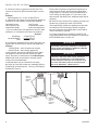
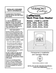
A confined space may be ventilated in two ways:
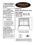
A) Open up or provide at least two ventilating grilles to
an adjoining unconfined space. Use any of the options
illustrated in Figure 4.
Each of the two grilles must provide an opening of at
least 50 square inches, with all opening dimensions
being at least 3”. One grille must be located within 12”
of the ceiling; the other within 12” of the floor. (If the
total exceeds 100,000 BTU/Hr, additional grilles will be
required.)
B) Vent the room directly to the outdoors. (Provide one
square inch of opening for each 4,000 BTU/hr.
If the total BTU/Hr used by the appliances is less than
the maximum BTU/Hr the space is able to support,
the room meets the Unconfined space criteria and no
further ventilation is required.
For further information on ventilation guidelines and
sizing specifications follow the National Fuel Gas Code
NFPA 54/ANSI Z223.1 Section 5.3.
WARNING
This heater shall not be installed in a confined
space unless provisions are made for adequate
combustion and ventilation air.
WARNING
If the area in which the heater may be operated is
smaller than that defined as an unconfined space,
provide adequate combustion and ventilation air by
one of the methods described in the National Fuel
Gas Code, ANSI Z223.1, 1992 Section 5.3.
12”
Option 1
Vents to
Adjoining
Room
Option 3 Vents to
Adjoining
Room
Option 2
- Remove
Door to
Adjoining
Rooms
12”
VO370-2
Fig. 4 Vent options to provide additional air.
8
vent370-2
Ventilation options
3/26/99 djt
20004555
Radiance Vent-Free Gas Heater
Assembly Procedures
Read these instructions thoroughly before starting
the assembly. Follow procedures in the order given.
Inspect the stove for damage before starting the
assembly. Do not install this stove if any damage is
evident. Contact your dealer immediately.
The Radiance is shipped on its back, mounted to a
wooden pallet. It is fully assembled, although packing
materials must be removed from the firebox and the
Log Set installed. Connection to the gas supply must
be performed only by a qualified gas technician who
should also verify that adequate ventilation is available
to support proper burner function.
Installation of optional accessories, such as the Fan,
Glass/Catalyst, or thermostat, is most easily accomplished before the gas supply connection is made.
Tools Required
•
•
•
•
Stub-handled Phillips screwdriver
• work gloves
Standard Phillips screwdriver
• knife
Standard flat-blade screwdriver
Tape measure
• needlenose pliers
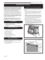
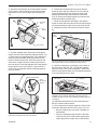
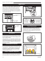
Remove the Front, Screen and Logs
Remove the Front panel, the Screen panel, the Log Set
and hardware bag from the firebox before positioning
the stove.
1. Remove the accessory package from the top of the
stove. The manual, hardware package, and lava
rocks are packed on top of the firebox. Set these
aside.
2. Remove the Front Plate. Grasp one side and the
bottom, and lift the front plate as a unit (the control
door attaches to the stove front). Swing the bottom
edge out and away from the stove body, (Fig. 5)
3. Remove the screen frame. (Fig. 6)
4. Remove the Log Set. Lift out the package and any
packing material from the burner tray and firebox.
Unpack the log set and inspect each piece for damage. DO NOT INSTALL DAMAGED LOGS. Set the
logs aside out of the way.
Hardware Bag Contents
•
•
•
•
•
•
•
•
Porcelain Handle (Front Door)
Control Door Handle & Screw
(2) Bags of Lava Rock
(6) 10 x 1/2” Screws
Bracket, Wire Switch
Registration Card & Manual
(4) CS, Hex Hd 3/8-16 x 1 Gr 2-Z
(4) Washer, Fl 3/8-Z
Unpacking the Radiance
Caution: Enamelled castings can chip easily! Handle enamelled castings carefully to avoid damage.
1. Cut the shipping straps.
2. Unpack the top grate and screen from the carton,
and set them aside.
ST139
Fig. 5 Remove the front plate.
ST139
Radiance
remove front
4/20/01 djt
Screen Hooks
ST187a
Fig. 6 Lift screen from firebox.
20004555
9
Radiance Vent-Free Gas Heater
Assemble the Legs
1. Slide stove to the rear of the pallet just far enough to
access rear leg holes. Make sure the stove does not
tip over backwards. (Fig. 7)
6. Remove pallet and allow stove to gently rest on all
four legs.
7. Adjust leg levelers to compensate for irregularities in
the hearth.
Install Optional Fan
It is easiest to install the optional fan kit #2767/FK26,
before the stove is moved to its final location or connected to the gas line.
The fan consists of a blower assembly and a rheostat switch that are connected by a wire harness. The
blower attaches to a bracket at the bottom of the rear
shroud. The rheostat installs at the bottom of the stove
on the left of the valve.
ST720
Fig. 7 Slide stove back just far enough to access rear leg
holes.
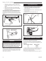
2. Attach the rear legs using 3/8” hex head bolts and
flat washer supplied.
Tighten with a 9/16” wrench or
ST720
socket.
Radiance
3. Carefully tip the stove onto its rear legs. Adjust the
slide stove back
pallet to allow access to one of the front leg holes.
7/30/02
djt the stove to prevent
Be sure to leave the
pallet under
the stove from falling fully forward. (Fig. 8)
CAUTION: To prevent valve tubing from being
crushed or damaged, make sure to rest valve on
wooden pallet.
The fan kit includes a ‘snapstat’, a temperature-sensing switch which will be mounted to the blower duct just
below the top plate of the stove. The snapstat automatically turns the fan on or off at approximately 109°F.
The rheostat provides a range of fan speed settings
from OFF (which overrides the snapstat function) to
high.
Kit Contents
• Fan assembly with rheostat and snapstat
• wire tie
• control knob
• retaining collar
CAUTION: Sheet metal edges can be sharp. Be sure to
wear protective gloves.
1. Loosen the four phillips head screws which secure
the rear shroud to the stove sides. (Fig. 9)
2. Carefully pull the shroud assembly away from the
rear of the stove.
3. With the rear shroud assembly in the upright position, set the bottom of the shroud on a padded surface
to prevent scratching the surface. Unfasten the four
phillips head screws which attach the outer shroud to
the inner duct assembly.
Washer
Hex Head Bolt
ST721
Fig. 8 Carefully tip stove onto back legs. Leave pallet under
stove to keep stove from falling fully forward.
ST721
4. Have your assistant Radiance
attach one leg using the hardware described.
attach
5. Move the pallet to allow
frontaccess
legs to the other front leg
hole. Attach remaining
leg.
7/30/02 djt
Rear Shroud Assembly
ST189
Fig. 9 Loosen four phillips screws holding rear shroud assembly and remove. Remove four phillips screws holding rear
shroud to inner duct assembly. Remove rear shroud.
10
20004555
ST189
fan remove shroud
radiance
11/99
Radiance Vent-Free Gas Heater
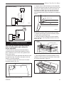
4. Attach the fan assembly to the fan bracket provided
in the log box. Use #10 sheet metal screws provided
with fan kit. Do not remove finger guard screws.(Fig.
10)
Snapstat
Wire
Rheostat
Wire
Fan
Bracket
6. Position the fan assembly so the ducts slide between the inner and outer shroud. The inner shroud
should engage with the two slots in the ends of the
bracket so that bracket and shroud are interlocked.
(Fig. 12) Secure the bracket with the four sheet metal
screws provided in the finish bag.
7. Route the rheostat wire assembly to the right between the inner and outer shroud. Run the wire through
the slots at the bottom right corner of the inner shroud.
8. Refasten the outer shroud to the inner duct assembly.
Slot
Outer
Shroud
{Inner Shroud}
Slot
Finger Guard
ST669
Fig. 10 Attach the fan assembly to the fan bracket.
5. Connect snapstat leads. Disconnect the snapstat
module from the leads inside the snapstat bracket. (Fig.
ST669
11) Bend open the
snapstat bracket. Use needlenose
RUVSOD
pliers to remove attach
the black
fan toplastic
bracket grommet from the
bracket. Discard7/01
the bracket. Insert the grommet and
wires into the large hole at the bottom right corner of
the inner shroud. Feed the snapstat wire leads through
the grommet into the stove interior. Connect the two
wires to the two snapstat extension leads attached to
the inner shroud.
ST194
Fig. 12 Position the fan to engage the inner shroud with the
fan bracket slots and secure with sheet metal screws.
ST194
9. Install the snapstatattach
by loosening
fan to shroud the front screw on
11/99 (Fig. 13) slide the snapstat
the inner side of the duct
under the head of the screw and tighten. Connect the
leads to the snapstat. Make sure the snapstat assembly
is mounted straight front to back.
Snapstat Bracket
Snapstat Module
Pinch
Grommet to
Remove
Snapstat
Left Air Duct
ST671
Fig. 13 Install the snapstat and connect the extension wire
terminals. View is with top removed, however, access is
available through the rear when installing fan before gas line
connection.
ST195
10. Slide shroud assembly
attach snapstatover the sides and fasten
11/99
the four screws loosened
earlier.
11. The rheostat control switch attaches to the left side
of the valve bracket at the front of the stove. (Fig. 14)
ST670
Fig. 11 Remove the snapstat and grommet from the bracket
and insert the grommet into the inner shroud.
20004555
ST640
RUVSOD
snapstat
7/01
• Remove retaining nut from shaft of rheostat. (if
•
preinstalled)
Insert the rheostat through the hole in the back
of the left side of the valve bracket, aligning the
locator pin with the smaller hole in that bracket.
11
Radiance Vent-Free Gas Heater
• Thread the retaining nut onto the shaft of the
rheostat, tightening with a wrench. Do not overtighten.
• Attach the control knob to the rheostat shaft.
• Use the wire tie to secure the fan and rheostat
wire harnesses together.
12. Plug the power cord into a standard grounded 110
volt household outlet. If the fan control knob is not
turned to the OFF position, the fan will turn on when
the temperature at the snapstat reaches approximately
109°F.
Install ON/OFF Switch
The switch assembly parts are found in the parts bag.
1. Attach switch assembly to left rear side of stove
shroud using two screws and existing holes in
shroud. (Fig. 16)
2. Run wires down back of stove, under bottom of rear
shroud to valve.
3. Attach wires to valve terminals. (Fig. 17)
Switch Assembly
Existing
Holes
Rheostat
Screws
Retaining Nut
Control Knob
WHT
GRN
BLK
BLK
TP
TPTH
BLK
BLK
MOTOR
ST347a
JUV power
Disconnect
before servicing.
FK28
rheostat install
9/21/00
TH
ST347a
Fig. 14 Attach rheostat to control panel. Valve may look different.
SNAPSTAT
WHT
ST228
ON/OFF
RHEOSTAT
ST315
attach switch assy
Thermostat Connection
(Optional)
ST228 1/31/00
djt
Fig. 17 Attach switch wires to valve.
POWER
ST196
Fig. 15 #2767 / FK26 Fan Wiring Diagram
WARNING
ST196
The optional fan
kit is equipped with a three-prong
FK26 fan diangram
(grounding) plug
for your protection against shock
11/99
hazard and should be plugged directly into a properly grounded three-prong outlet. Do not cut or
remove the grounding prong from this plug.
NOTE: If you are installing the fan kit after the stove is
in its final location, follow same steps mentioned previously with the exception of disengaging only the right
side of the outer shroud.
12
ST315
Fig. 16 Attach switch assembly to rear shroud.
switch
Use only a thermostat attach
rated for
500 - 750 millivolts.
wires thermostats.
to valve
Do not use low voltage (24V)
12/99
Check the table below for the appropriate gauge thermostat wire to use for the length of lead required in your
installation.
Thermostat Wire / Gauge
Maximum Run
18
40 feet
20
25 feet
22
16 feet
1. Install the wall thermostat in the desired location and
run the wires to the stove location. Terminate these
leads with 1/4” female connectors.
2. Connect the thermostat wires to the valve. (Fig. 17)
20004555
Radiance Vent-Free Gas Heater
On/Off Switch Wiring
Thermopile
Black
4. Replace burner. Slide the burner in at an angle with
left side lower than the right side. Slide the left side onto
the injectors, making sure the burner leg remains at a
90° angle to the base. (Fig. 19) Lower the right hand
side down in to place. Make sure the burner is as far
left as possible and the injector shoulders are inside the
burner.
ON
OFF
TP/TH
Left Burner Leg
Injector Orifices
Millivolt
Gas Valve
TP
Black
TH
Optional Thermostat Wiring
Thermostat
(Optional)
90°
ST124b
Thermostat
(Optional)
TP/TH
TP
TH
Thermopile
Black
ST353a
St124b
on/off/switch
wiring
1/11/00 djt
Fig. 19 Be sure injector orifices remain at 90° to the base.
Millivolt
Gas Valve
Black
5. Replace left and right log bracket assembly, tighten
rear log bracket, and replace logs.
6. Latches provided in catalyst kit must be installed
on top of firebox. Use two phillips screws to secure in
place. (Fig. 20) ST353a
ST124c
Phillips
Screws
Glass & Catalyst Installation
injector orifice
replace
3/21/00 djtCatalyst Location
Phillips Screws
CAUTION: Air shutter must be removed
when installing glass and catalyst for
proper operation.
St124c
1. Remove left and
right log bracket assembly by
Thermostat
unfastening the two screws which hold the burner in
wiring
place. Loosen the screw on the rear log bracket and
1/11/00 djt
remove the bracket.
2. Hold the burner at the right hand side and lift to clear
the right burner leg. Then pull to the right to clear the
injectors on the left hand side.
3. Turn burner upside down and remove air shutter.
Discard air shutter. (Fig. 18)
ST671
Fig. 20 Attach glass latches.
7. Slide catalyst between top plate and firebox. Allow
catalyst to “fall” into hole on top of firebox. Secure with
two screws as shown in Figure 21.
Air Shutter (Remove and Discard)
Bottom of Burner Pan
ST187
Fig. 21 Install catalytic
combustor.
ST667
ST201
pull frame latches
11/99
Fig. 18 Remove air shutter and discard.
20004555
ST667
RNVOD
air shutter
converting
13
ST201
remove catalytic
combustor
11/99
Radiance Vent-Free Gas Heater
8. Install glass frame assembly by resting the bottom edge of the frame on support brackets below the
front opening of the firebox. Swing the top edge of the
assembly toward the firebox, and center it. Fasten by
closing the latches over the top left and right edges of
the frame. (Fig. 22)
CAUTION
This appliance should only be connected
by a qualified gas technician. Test to
confirm manifold pressures as specified
below.
The Radiance Heater and its individual shutoff
valve must be disconnected from the gas supply
piping during any pressure testing of that system
at test pressures in excess of 1/2 psig (3.5 kPa).
ST672
Fig. 22 Set glass frame in place and secure latches.
Connect the Gas Supply Line
Check the Rating Plate attached by a steel cable to the
firebox, to confirm that you have the appropriate firebox
for the type of fuel to be used.
This appliance should only be connected by a qualified gas technician. Test to confirm manifold pressures as specified below.
The Radiance Heater and its individual shutoff valve
must be disconnected from the gas supply piping
during any pressure testing of that system at test
pressures in excess of 1/2 psig (3.5 kPa).
ST187
The Radiance Heater
must
be isolated from the
pull frame
latches
gas supply piping
system
by
closing its individual
11/99
manual shutoff valve during any pressure testing of
the gas supply piping system at test pressure equal
to or less than 1/2 psig.
There must be a gas shutoff between the stove and
the supply.
In order to connect Natural Gas, use a fitting with
3/8” NPT nipple on the valve side and 1/2” natural
gas supply line with an input of 35,000 BTUs at a
manifold pressure of 3.5” and minimum inlet supply
for adjustment of 5.5” w.c.
In order to connect Propane, use a fitting with 3/8”
NPT nipple on the valve side and 1/2” propane gas
supply line with an input of 35,000 BTUs at a manifold pressure of 11.0” and minimum inlet supply for
adjustment of 11.0” w.c.
Gas connection should be made in accordance with
current National Fuel Gas Code, ANSI Z223.1. Since
some municipalities have additional local codes, be
sure to consult you local authority.
Connect the gas supply and test for leaks. Use a 50/50
solution of liquid soap and water to test for leaks at gas
fittings and joints. NEVER test with an open flame.
Light the pilot according to the directions on page 16,
before going to the next step.
14
The Radiance Heater must be isolated from the
gas supply piping system by closing its individual manual shutoff valve during any pressure
testing of the gas supply piping system at test
pressure equal to or less than 1/2 psig.
There must be a gas shutoff between the stove
and the supply.
In order to connect Natural Gas, use a fitting
with 3/8” NPT on the valve side and 1/2” natural
gas supply line with an input of 35,000 BTUs at a
manifold pressure of 3.5” between minimum inlet
supply of 5.5” w.c. and maximum of 14.0” w.c.
In order to connect Propane, use a fitting with 3/8”
NPT on the valve side and 1/2” propane gas supply line with an input of 35,000 BTUs at a manifold
pressure of 11.0” between a minimum inlet supply
of 11.0” w.c. and maximum of 14.0” w.c.
Install Log Set
1. Remove the logs from their packaging, and inspect
each piece for damage. DO NOT INSTALL DAMAGED LOGS.
2. Install the rear left log by placing it on the sheet
metal shelf at the back of the firebox. (Fig. 23) The
log should touch the back wall of the firebox. Slide
the log to the left until the left side lines up with the
left bracket. (Fig. 23) When the log is in place the
left front corner of the log should rest on the decorative grate.
3. Install the rear right log by placing it on the sheet
metal shelf at the back toward the right. Make
sure the right side of the log lines up with the right
bracket. (Fig. 23) NOTE: When the right and left rear
logs are in place, they should touch the back of the
firebox and each other.
4. Install the right log by engaging hole on the bottom
with pin on the right rear log. (Fig. 23) Set the bottom
of the log on the bracket and bring forward to come
in contact with decorative grate on right.
20004555
Radiance Vent-Free Gas Heater
Complete the Installation
Right Log
Right Rear Log
Left Rear Log
Left Bracket
LG171
Decorative
Grate
Right Bracket
Fig. 23 Install the left and right rear logs and the right log.
LG156
Radiance logs
4/23/01 djt
Log rests on
decorative grate
1. Replace the screen frame by sliding the hooks over
the top front edge of the firebox and resting the bottom on the support brackets. If the catalyst has been
installed, place the glass front on the stove by resting the bottom edge of the frame on support brackets below the front opening of the firebox. Swing the
top edge of the assembly toward the firebox, and
center it. Fasten it by closing the latches over the top
left and right edges of the frame.
2. Replace the stove front by grasping it by the left and
right edges. Lift it so that tabs on the back side of
the top corners engage notches at the top forward
corners of the stove sides. Then gently swing the
bottom of the front panel to a vertical position, and
lower it till prongs on its bottom left and right corners
engage with notches cast into the tops of the forward
legs. (Fig. 26) Test that the front is installed securely
by grasping two of panel’s vertical bars, and pulling
the panel toward yourself. When the panel is in place
properly you should not be able to pull the bottom of
the front toward yourself without also lifting it.
3. Attach the wooden handle to the control door using
the #8-32 x 2” screw from the parts bag. (Fig. 27)
4. Set the screen and the cast-iron grate into the recess in the stove top.
This completes the installation and assembly of the
Radiance RUVSOD.
Lava Rock
LG172
Fig. 24 Completed log
installation.
LG155
5. Loosely sprinkle the lava rocks directly on top of the
Radiance logs
burner just behind decorative grate. (Fig. 25) Use
the lava rock toinstalled
cover brackets on the burner. Do
4/24/01
djt back of burner. The lava
not place lava rocks
toward
rock is shipped inside the bag assembly.
Left Rear Log
Top View
Right Rear
Log
ST139a
Fig. 26 Replace the front panel.
ST139a
Radiance
replace front
7/24/01 djt
Lava rock may
be placed in this
area
Decorative Grate
LG160
Fig. 25 Lava rock placement.
LG160
RNV logs
top view
6/4/01 djt
ST197
Fig. 27 Attach the handle to the control door.
20004555
15
ST197
RUVS attach accessory door handle
7/01
Radiance Vent-Free Gas Heater
Operation
The Radiance is shipped with the operable door front
plate. The stove may be operated with the doors either
open or closed. To open the front doors, insert the
handle provided into the door latch stub and turn it to
the right and up. (Fig. 28) When not in use, the handle
may be stored in the handle holder on the right side of
the rear shroud. (Fig. 29)
Natural
Pilot
Counterclockwise
to Open
ST673
LP Pilot
ST673location.
Fig. 30 Pilot assembly
Clockwise
to Close
ST621
Fig. 28 To open the front doors, turn handle counterclockwise.
Turn
counterclockwise
to decrease
flame height
LO
RUVSOD
Pilot assembly location
7/249/01 djt
HI
Turn clockwise
to increase
flame height
Fig. 31 Flame adjustment knob for Honeywell valve.
Handle
Holder
RADIANCE
ST656
Fig. 29ST621
When not in use, store handle in the handle holder.
Flame Characteristics
It is important to periodically perform a visual check
of the pilot and burner flames.
HV102 Compare them to the
illustration below. (Fig. 32,
33) If the
Honeywell
hi/loflame
knob patterns appear abnormal, contact 4/5/99
a qualified
service
provider for
djt
service and adjustment.
Radiance Your First Fire
operable doors
Read these instructions carefully and familiarize your1/31/01
self with
the burner controls shown on Page 17. Locate
the pilot assembly, Figure 30. Follow the lighting instructions on Page 16 exactly.
During the first fire, it is not unusual to smell some odor
associated with new logs, paint and metal being heated.
Odors should dissipate within the first eight to ten hours,
however, you can open a window to provide fresh air to
alleviate the condition.
ST624
handle holder
Each time you light your heater check that the pilot
flame and burner flame 2/6/01
patterns are as shown in Figure
ST198
Fig. 32 Correct pilot flame appearance. OP pilot.
Pilot and Burner Inspection
32 and Figure 33. If flame patterns are incorrect, turn
the heater off. Contact your dealer or a qualified gas
technician for assistance. Do not operate the heater
until the pilot flame is correct.
ST198
pilot flame detail
11/99
Flame & Temperature Adjustment
For units equipped with HI/LO valves, the flame adjustment is accomplished by rotating the HI/LO adjustment
knob located near the center of the gas valve. (Fig. 31)
Red Glow
LG173
Fig. 33 Correct burner flame pattern.
16
LG155
Radiance logs
installed
20004555
Radiance Vent-Free Gas Heater
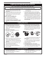
Lighting and Operating Instructions
FOR YOUR SAFETY READ BEFORE LIGHTING
WARNING:If you do not follow these instructions exactly, a fire or explosion
may result causing property damage, personal injury or loss of life.
A. This heater has a pilot which must be lit manually. When lighting the pilot follow these instructions exactly.
B. BEFORE LIGHTING smell all around the heater
area for gas. Be sure to smell next to the floor
because some gas is heavier than air and will
settle on the floor.
WHAT TO DO IF YOU SMELL GAS
• Do not try to light any fireplace
• Do not touch any electric switch
• Do not use any phone in your building
• Immediately call your gas supplier from a neighbor’s phone. Follow the gas supplier’s instructions.
•
If you cannot reach your gas supplier, call the
Fire Department
C. Use only your hand to push in or turn the gas
control knob. Never use tools. If the knob will not
push in or turn by hand, do not try to repair it, call a
qualified service technician. Applying force or any
attempted repair may result in a fire or explosion.
D. Do not use this fireplace if any part has been under
water. Immediately call a qualified service technician to inspect the heater and to replace any part of
the control system and any gas control which has
been under water.
Lighting Instructions
1. STOP! Read the safety information above.
2. Turn off all electrical power to the fireplace.
3. For MN/MP/TN/TP appliances ONLY, go on to
Step 4. For RN/RP appliances turn the On/Off
switch to “OFF” position or set thermostat to
lowest level.
4. Open control access panel.
5. Push in gas control knob slightly and turn
clockwise
to “OFF”.
3/8" - 1/2"
OFF
ON
OFF
OFF
3 4 5
Euro SIT
ON
1 2
P
OFF ilot
PI
LO
T
PILOT
10. Push the control knob all the way in and hold.
Immediately light the pilot by repeatedly depressing the piezo spark ignitor until a flame appears.
Continue to hold the control knob in for about one
(1) minute after the pilot is lit. Release knob and it
will pop back up. Pilot should remain lit. If it goes
out, repeat steps 5 through 8.
SIT NOVA
Honeywell
6. Wait five (5) minutes to clear out any gas. Then
smell for gas, including near the floor. If you
smell gas, STOP! Follow “B” in the safety inforFP1067
mation above. If you
do not smell gas, go to the
lighting instruction
next step.
knobs
7. Remove glass door
before
3/9/01
djt lighting pilot. (See
Glass Frame Removal section).
8. Visibly locate pilot by the main burner.
9. Turn knob on gas control counterclockwise
to “PILOT”.
•
If knob does not pop up when released, stop
and immediately call your service technician or
gas supplier.
FP1068
•
If after several tries,
the pilot
will not stay lit,
Lighting
instructions
turn the gas control knob
to “OFF” and call your
Pilots
service technician or gas supplier.
11. Replace glass door.
12. Turn gas control knob to “ON” position.
13. For RN/RP appliances turn the On/Off switch to
“ON” position or set thermostat to desired setting.
14. Turn on all electrical power to the fireplace.
To Turn Off Gas To Heater
1. Turn the On/Off switch to Off position or set the
thermostat to lowest setting.
2. Turn off all electric power to the fireplace if
service is to be performed.
20004555
3. Open control access panel.
4. Push in gas control knob slightly and turn clockwise
to “OFF”. Do not force.
5. Close control access panel.
17
Radiance Vent-Free Gas Heater
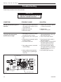
Troubleshooting
Follow these procedures in the order presented.
WARNING
TURN OFF HEATER AND ALLOW TO COOL
COMPLETELY BEFORE SERVICING.
CONDITION
POSSIBLE CAUSE
SOLUTION
No spark at pilot when Ignitor is
operated.
1. Ignition Electrode is disconnected
from ignition wire, broken or incorrectly positioned.
2. Ignitor wire is broken.
3. Bad Piezo Ignitor.
1. Inspect and re-connect, replace
or repair as necessary.
1. Gas supply is turned off or supply
line shut-off valve is closed.
2. Control Knob is not in PILOT position.
3. Control Knob not pressed in while
in PILOT position.
4. Air present in gas lines.
1. Turn on gas supply or open supply line shut-off valve.
2. Turn Control Knob to PILOT.
The Ignitor Electrode sparks,
but Pilot does not light.
5. Inlet supply pressure is not within
correct settings.
6. Other conditions that should be
identified only by a qualified gas
technician.
2. Replace wire.
3. Replace Piezo Ignitor.
3. Press Control Knob in while in
the PILOT position.
4. Continue holding in Control Knob
and repeat ignition procedure
until air is bled from the lines.
5. Call local gas supplier. Adjust
inlet supply pressure to specification: NG; 5.5” w.c.-14.0”w.c. LP;
11.0” w.c.-14.0”w.c.
6. Call qualified gas technician.
OFF
O H
PILOT
ADJ
ON
L
I
PI
LO
T
Piezo Ignitor
Regulator
Pilot / Main Control
HV104
Fig. 34 Honeywell valve assembly.
18
HV104
Honeywell Valve
with pilot 2
7/9/99 djt
20004555
Radiance Vent-Free Gas Heater
Troubleshooting cont’d.
CONDITION
POSSIBLE CAUSE
SOLUTION
Pilot lights but flame goes out
when Control Knob is released.
1. Control Knob not fully depressed
or held in long enough.
2. Gas supply line shut-off valve is
not fully open.
3. Thermocouple connection is
loose at the Control Valve.
1. Depress Control Knob fully and
hold in for a full 30 seconds.
4. Pilot flame does not touch the
Thermocouple.
This can be caused by:
A) Incorrect gas pressure, and/or
B) other conditions that should
be identified only by a qualified
service technician.
4. A) Call local gas supplier. Adjust
inlet supply pressure to specification: NG; 5.5” w.c.-14.0”w.c. LP;
11.0” w.c.-14.0”w.c.
B)Call local gas service technician.
5. Thermocouple is damaged.
6. Control Valve is damaged.
5. Call local gas service technician.
6. Call local gas service technician.
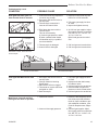
Pilot flame is lifting.
Thermopile
Thermocouple
ST121a
2. Fully open gas supply line shutoff valve.
3. Inspect and tighten securely.
Pilot flame is weak - does not touch
Thermocouple.
ST121a
JUV
Pilot flame wrong 2
9/25/00 djt
Correct LP Pilot Flame.
Correct NG Pilot Flame.
Pilot lights but Main Burner does
not.
1. Gas supply
line shut-off valve is
ST674
not fully open.
RUVSOD
2. Foreign material is blocking
Pilot flame 2
Burner ports.
7/24/01
3. Main Burner
orifice is djt
clogged.
4. Thermostat or remote switch not
activated on JUVS.
5. Bad Thermopile.
1. Fully open gas supply line shutoff valve.
2. Insptect and clear debris away
from Burner ports.
3. Call local gas service technician.
4. Set thermostat to higher temperature or check remote switch.
5. Call local gas service technician.
Main Burner shuts off and Pilot
flame goes out while in operation.
1. Insufficient fresh air.
1. Determine that adequate ventilation exists to provide sufficient
fresh air. Open a window or provide additional ventilation. (See
Fresh Air Requirements, Pages
7-8)
2. Call local gas supplier. Adjust
inlet supply pressure to specification: NG; 5.5” w.c.-14.0”w.c. LP;
11.0” w.c.-14.0”w.c.
2. Incorrect inlet supply pressure.
20004555
19
Radiance Vent-Free Gas Heater
Maintenance
The following procedures will help ensure that your
heater continues to perform safely and efficiently.
Screen Hooks
Firebox Cleaning and Inspection
Cleanliness is critical to correct operation of the
heater. The log set, burner, valve controls and air
circulation areas must all be kept free of dust and
unobstructed by debris. Inspect these areas before
each use and clean whenever accumulation is evident. Follow the simple procedure outlined below.
Frequent cleaning may be necessary in living environments subject to excessive carpet lint or pet hair. For
example, if you live with a dog that sheds continuously,
you will need to inspect the burner area frequently and
clean it as often as the accumulation requires. In extreme conditions, it may be necessary to clean the
burner and log set monthly or bi-weekly.
This appliance should be inspected and thoroughly
cleaned annually by a qualified gas technician.
Cleaning Procedure
1. Turn the burner OFF and let the heater cool completely before cleaning.
2. Lift the Front plate up and then swing the bottom out
to disengage it from the heater shell. (Page 9, Fig.
5)
3. Remove the screen by lifting up and away from the
unit. Or, if so equipped, remove the glass panel by
releasing the two upper retainer latches. Lift the
panel up and off of the firebox frame. (Fig. 35)
4. Carefully inspect the log set for damage. Contact
your local dealer if any damage is evident. DO NOT
OPERATE THE HEATER WITH A DAMAGED OR
LOOSE LOG SET.
Use a soft-bristled brush vacuum cleaner attachment to remove dust or debris from the log set, pilot
and burner. Use care as the log set is fragile.
5. Inspect the catalytic combustor at the top of the
firebox. Replace the combustor if any damage or
deterioration is evident.
6. Replace the screen or glass panel and the front
plate. DO NOT OPERATE THE HEATER WITH
THE SCREEN / GLASS PANEL OR FRONT PLATE
REMOVED.
20
Glass Latch
ST675
Fig. 35 Remove the screen or glass panel.
Glass Replacement
If so equipped, do not operate this appliance with the
glass panel cracked, broken, or removed. Replace
damaged glass only with CFM Corporation ceramic
glass panel Part No. 1601290. Follow the Cleaning
Procedure instructions regarding parts removal.
ST675
Care of Cast Iron
RUVSOD
An occasional dusting
with a dry ragremoval
will help keep the
screen/glass
painted surfaces looking new. Use high-temperature
7/01
stove paints, available through your local dealer, to
touch-up areas as needed. Clean areas to be painted
with a wire brush and be sure to cover the log set,
burner and valve assembly. Apply the paint sparingly;
two light coats of paint will give better results than a
single heavy coat.
Porcelain enamel surfaces should be cleaned with a
soft, damp cloth. Do not use abrasive cleaning agents.
If necessary, use only a cleaning agent formulated specifically for use on porcelain enamel surfaces.
WARNING
Turn the burner Pilot OFF before applying paint.
NEVER paint pilot or around pilot area.
WARNING
Dust and debris accumulation can result in poor
performance. Inspect the Valve compartment,
burner parts and log set frequently and Clean
these parts monthly or as often as accumulation warrants.
20004555
Radiance Vent-Free Gas Heater
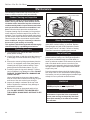
Catalytic Combustor
The combustor should be cleaned annually to ensure
optimal performance. Follow the procedure below.
Remove the Combustor Module
1. Be sure the heater is COLD.
2. Remove the front plate, top grille and screen. (Fig. 36)
3. Use the phillips screwdriver to remove the two sheet
metal screws that secure the combustor to the top of
the firebox. (Fig. 37) Use a flat screwdrive to lift the
unit up and out through the front of the stove.
Clean the Combustor Module
1. Clean the outer surface of the filter with the brush attachment of your vacuum sweeper to remove loose
dirt.
2. Submerge the filter in a mild soapy water solution.
Rinse thoroughly with distilled water.
3. Replace in heater when dry.
Replace the Combustor Module
ST139
Fig. 36 Remove the front plate and top grille/screen.
ST139
Radiance
remove front
4/20/01 djt
1. Slide the combustor through the front opening of
the stove and insert it into the housing on top of the
firebox. Secure with the two sheet metal screws.
2. Replace the glass panel and front.
ST201
Fig. 37 Remove the catalytic combustor module.
ST201
remove catalytic
combustor
11/99
20004555
21
Radiance Vent-Free Gas Heater
5
6
2
1a
3
4
25
7
1b
1c
8
9
17
PILOT
ADJ
11a
16
I
L
ON
11b
O H
18
PI
LO
T
OFF
10a,b
12a,b
15
14
19
13
20
23
21
27
28
22
30
24a,b,
c,d
29
4555
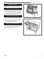
CFM Corporation reserves the right to make changes in design, materials, specifications, prices and discontinue colors and products at any time,
without notice.
Radiance Vent Free Gas Heater (RUVSOD)
Models: 3237 thru 3244, 3357,
3358, 3370 thru 3379
4555
Ref.
1.
1a.
1b.
1c.
2.
3.
4.
5.
6.
7.
22
Description
Gas Logset - RUVSOD
Right Rear Log RUVSOD
Left Rear Log RUVSOD
Right Log RUVSOD
Manifold Assembly
Lava Rocks Burner
Screen, RUVSOD
Frame, Glass - RDV40
Gasket, Glass Med, Knit - RDV40
Trim ON/OFF Switch
RUVSOD
PARTS
7/24/01 djt
RUVSOD
20004561
20004562
20004563
20004564
20003739
57897
20004554
1409112
1203702
53606
20004555
Radiance Vent-Free Gas Heater
Radiance Vent Free Gas Heater (RUVSOD)
Models: 3237 thru 3244, 3357, 3358, 3370 thru 3379 (continued)
Ref.
8.
9.
10a.
10b.
11a.
11b.
12a.
12b.
13.
14.
15.
16.
17.
18.
19.
20.
21.
22.
23.
24a.
24b.
24c.
24d.
25.
26.
27.
28.
29.
30.
31.
Description
Handle Package, Ceramic w/Screw
Damper Steel Handle/Screw
Valve NG Honeywell - VS84212003
Valve LP Honeywell - VS84212011
Oxygenerator, NG OP #8204
Oxygenerator, LP OP #8404
Burner Housing Assy. - RUVSODRN
Burner Housing Assy. - RUVSODRP
Grate Decorative Burner
Back Log Support Bracket RUVSOD
Ignitor Piezo - Honeywell #396079
Front II, RDVOD
Door Left, RDVOD
Door Right, RDVOD
Door, RDVOD
Control Door Handle Assy.
Gasket, Base Pan/Firebox - RDV
Bracket, Log Right
Bracket, Log Left
Orifice Hood #57 (0.043”) - Front - LP
Orifice Hood #52 (.0635”) - Front - NG
Orifice Hood #54 (.055”) - Rear - LP
Orifice Hood #40 (.098”) - Rear - NG
Glass, GFP Firebox (Comes with RGDCFK)
Catalyst, RUV (not shown) (Comes with RGDCFK)
Left End
Right End
Leg
Top
Glass Frame Assembly (glass, gasket, frame)
RUVSOD
0004345
30002720
10000235
10000242
55464
55465
20004492
20004552
20003536
20004553
20000062
Refer to Enamel Parts Chart Page 23
Refer to Enamel Parts Chart Page 23
Refer to Enamel Parts Chart Page 23
Refer to Enamel Parts Chart Page 23
30002730
20004286
20005259
20004708
20004587
30000331
20000130
20004263
1601290
30000506
Refer to Enamel Parts Chart Page 23
Refer to Enamel Parts Chart Page 23
Refer to Enamel Parts Chart Page 23
Refer to Enamel Parts Chart Page 23
5003075
Shell Enamel Part Numbers
Model
Number
3370, 3375
3237, 3241
3371, 3376
3238, 3242
3239, 3243
3374, 3379
3373, 3378
3372, 3377
3357, 3358
3240, 3244
20004555
Color
Classic
Biscuit
Bordeaux
Chestnut
Brown
Ebony
Forest
Green
Midnight
Blue
Sand
Suede
Brown
Vermont
Cl. Green
Top
1301186
30003278
2321186
30003279
Left
End
30001751
30003239
30001771
30003248
Right
End
30001752
30003238
30001770
30003247
30003280
2311186
30003257
30001780
2371186
Front
30001376
30003240
30001416
30003249
Left
Door
30001378
30003242
30001418
30003251
Right
Door
30001377
30003241
30001417
30003250
Control
Door
30001413
30003243
30001419
30003252
Leg
(4)
30001753
30003245
30001772
30003254
30003256
30001779
30003258
30001428
30003260
30001430
30003259
30001429
30003261
30001431
30003263
30001781
30001777
30001776
30001424
30001426
30001425
30001427
30001778
1321186
30002557
30001774
30002512
30001773
30002511
30001420
30002514
30001422
30002516
30001421
30002515
30001423
30002517
30001775
30002518
30003281
30003266
30003265
30003267
30003269
30003268
30003270
30003272
23
Radiance Vent-Free Gas Heater
Optional Accessories
Fan Kits
FK26 Fan
The FK26 fan helps distribute heated air from within
the firebox out into the room. The fan is controlled by a
snapstat that turns power on and off as the firebox temperature rises above and falls below a preset temperature. A rheostat provides for variable fan speeds.
Specifications
Screen Kit
An optional screen, R40SK, is avaialble for use with the
operable doors to allow the doors to be left in the open
position.
Warming Shelf
Warming shelves add versatility to your stove; they can
be used to keep foods warm at mealtime.
Model Color
115 Volt / 60Hz / .75 Amps
Maintenance
The fan itself does not require regular maintenance,
however, periodic cleaning of the fan and the surrounding area is required.
Installation
Refer to Page 10 for installation instructions.
Remote Controls
The remote control allows you to turn the heater on or
off from anywhere in the room. Refer to Page 40 for
wiring diagrams.
Model
Functions Controlled
RC1
RC2
IMTFK
ON/OFF
ON/OFF and Temperature
Wall mounted thermostat control
1560
1555
1556
1557
1558
1562
1565
1566
1567
1568
Classic Black
Biscuit
Chestnut Brown
Ebony
Vermont Classic Green
Sand
Bordeaux
Forest Green
Midnight Blue
Suede Brown
The shelf installation is done in three stages. First you
attach the shelf loosely to the stove, leaving the screws
loose enough to allow final adjustments. Then, you position the shelf and adjust the brackets so the shelf fits
correctly. Finally, you tighten the screws.
Refer to the instructions included with each warming
shelf for complete installation procedures.
Glass & Catalyst Kit
The Glass & Catalyst, RGODCFK, may be added to the
stove to enhance stove performance. Refer to Page 12
for installation instructions.
24
20004555
Radiance Vent-Free Gas Heater
20004555
25
Radiance Vent-Free Gas Heater
26
20004555
LIMITED LIFETIME WARRANTY Radiance Vent-Free Gas Heater
PRODUCT COVERED BY THIS WARRANTY
All Vermont Castings gas stoves, gas inserts, and gas fireplaces, and all Majestic brand gas fireplaces
equipped with an Insta-Flame Ceramic Burner, or standard steel tube burner.
BASIC WARRANTY
CFM Corporation (hereinafter referred to collectively as the Company)
warrants that your new Vermont Castings or Majestic Gas Fireplace/
Stove is free from manufacturing and material defects for a period of
one year from the date of purchase, subject to the following conditions
and limitations.
EXTENDED LIFETIME WARRANTY
The heat exchanger, where applicable, and combustion chamber
of every Vermont Castings or Majestic gas product is warranted for
life against through wall perforation. All appliances equipped with an
Insta-Flame Ceramic Burner have limited lifetime coverage on the
ceramic burner plaque. Warrantees are made to the original owner
subject to proof of purchase and the conditions and limitations listed
on this Warranty Document
•
•
•
•
COMPONENT WARRANTY
CAST IRON: All external and internal cast iron parts are warranted for a
period of three years.
Note: On porcelain enamel finished external parts and accessories
The Company offers no Warranty on chipping of enamel surfaces.
Inspect all product prior to accepting it for any damage to the
enamel.
The salt air environment of coastal areas or a high humidity
environment can be corrosive to the porcelain enamel finish. These
conditions can cause rusting of the cast iron beneath the porcelain
enamel finish, which will cause the finish to flake off.
Dye lot variations with replacement parts and/or accessories can
occur and are not covered by warranty.
GLASS DOORS: Glass doors are covered for a period of one year.
Glass doors are not warranted for breakage due to misuse or accident.
Glass doors are not covered for discoloration or burned in stains due to
environmental issues, or improper cleaning and maintenance.
BRASS PLATED PARTS AND ACCESSORIES: Brass parts should be
cleaned with Lemon oil only. Brass cleaners cannot be used. Mortar
mix and masonry cleaners may corrode the brass finish. The Company
will not be responsible for, nor will it warrant any brass parts which are
damaged by external chemicals or down draft conditions.
GAS VALVES: Gas valves are covered for a period of one year
•
•
•
•
•
•
ELECTRONIC AND MECHANICAL COMPONENTS: Electronic and
mechanical components of the burner assembly are covered for one
year. All steel tube burners are warranted for one year.
ACCESSORIES: Unless otherwise noted all components and CFM
Corporation company supplied accessories are covered for a period of
one year.
CONDITIONS AND LIMITATIONS
•
•
•
•
This new Vermont Castings or Majestic product must be installed or
serviced by a qualified installer, preferably NFI or WETT (Canada)
certified, as prescribed by the local jurisdiction. It must be installed and
operated at all times in accordance with the Installation and Operating
instructions furnished with the product. Any alteration, willful abuse,
accident, or misuse of the product shall nullify this warranty.
This warranty is non-transferable, and is made to the original owner,
provided that the purchase was made through an authorized supplier
of the Company.
The customer must pay for any Authorized Dealer in-home travel fees
or service charges for in-home repair work. It is the dealers option
whether the repair work will be done in the customer’s home or in the
dealer’s shop.
If upon inspection, the damage is found to be the fault of the manufacturer,
repairs will be authorized at no charge to the customer parts and/or
labor.
20004555
•
Any part and/or component replaced under the provisions of this
warranty is covered for six months or the remainder of the original
warranty, whichever is longest.
This warranty is limited to the repair of or replacement of part(s) found
to be defective in material or workmanship, provided that such part(s)
have been subjected to normal conditions of use and service, after
said defect is confirmed by the Company’s inspection.
The company may, at its discretion, fully discharge all obligations
with respect to this warranty by refunding the wholesale price of the
defective part(s)
Any installation, labor, construction, transportation, or other related
costs/expenses arising from defective part(s), repair, replacement,
or otherwise of same, will not be covered by this warranty, nor shall
the Company assume responsibility for same. Further, the Company
will not be responsible for any incidental, indirect, or consequential
damages except as provided by law.
SOME STATES DO NOT ALLOW FOR THE EXCLUSION OR
LIMITATIONS OF INCIDENTAL AND CONSEQUENTIAL DAMAGES
OR LIMITATIONS ON HOW LONG AN IMPLIED WARRANTY
LASTS, SO THE ABOVE LIMITATIONS MAY NOT APPLY TO YOUR
CIRCUMSTANCES. THIS WARRANTY GIVES YOU SPECIFIC
RIGHTS AND YOU MAY HAVE OTHER RIGHTS WHICH VARY FROM
STATE TO STATE.
All other warranties-expressed or implied- with respect to the product,
its components and accessories, or any obligations/liabilities on the
part of the Company are hereby expressly excluded.
The Company neither assumes, nor authorizes any third party to
assume on its behalf, any other liabilities with respect to the sale of
this Vermont Castings or Majestic product
The warranties as outlined within this document do not apply to
chimney components or other non CFM Corporation accessories used
in conjunction with the installation of this product..
Damage to the unit while in transit is not covered by this warranty but
is subject to claim against the common carrier. Contact the dealer
from whom you purchased your fireplace/stove (do not operate the
appliance as this might negate the ability to process the claim with the
carrier).
The Company will not be responsible for:
a) Down drafts or spillage caused by environmental conditions such
as near-by trees, buildings, roof tops, hills, or mountains.
b) Inadequate ventilation or negative air pressure caused by
mechanical systems such as furnaces, fans, clothes dryers, etc.
This warranty is void if:
a) The fireplace has been operated in atmospheres contaminated by
chlorine, fluorine, or other damaging chemicals.
b) The fireplace has been subjected to prolonged periods of dampness
or condensation
c) Any damages to the fireplace, combustion chamber, heat exchanger
or other components due to water, or weather damage, which is the
result of but not limited to, improper chimney/venting installation.
d) Any alteration, willful abuse, accident, or misuse of the product
has occurred.
IF WARRANTY SERVICE IS NEEDED…
1) Contact your supplier. Make sure you have your
warranty, your sales receipt, and the model/serial
number of your CFM Corporation product.
2) DO NOT ATTEMPT TO DO ANY SERVICE WORK
YOURSELF.
27
CFM Corporation
410 Admiral Blvd. • Mississauga, Ontario, Canada L5T 2N6
800-668-5323 • www.cfmcorp.com