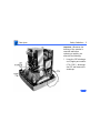
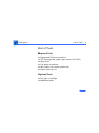
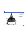
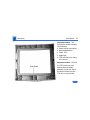
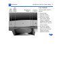
1
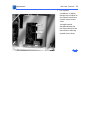
K Service Source
Apple Multiple Scan 720 Display
K Service Source
Hot Issues
Apple Multiple Scan 720 Display
Hot Issues
Introduction - 1
Introduction
This chapter is designed to highlight unique or highpriority product issues that you should be aware of before
servicing this display.
This chapter alerts you to important issues and provides
links to other areas in the manual where more complete
information can be found. This chapter is not intended to
replace other parts of this manual; it merely provides a
pointer to pertinent information in those chapters.
Hot Issues
Jittery or Blurry Video with Power Macintosh 5500/6500 - 2
Jittery or Blurry Video with Power
Macintosh 5500/6500
If the display exhibits jittery or blurry video when
connected to a Power Macintosh 5500 or 6500, suspect the
computer, not the monitor.
Video jitter affects monitors connected to computers having
a 225 or 250 MHz logic board. Jitter is evident where the
pixels shimmer or jump at the edges of the screen, windows,
or dialog boxes.
Blurry video is seen as a fuzzy image over the entire screen
on monitors set to resolutions of 832x624 and higher.
Hot Issues
Jittery or Blurry Video with Power Macintosh 5500/6500 - 3
Identifying Suspect Units
Video jitter or blurry video can be caused by Power
Macintosh computers within the following serial number
ranges.
Video Jitter
• PM 5500 from TY705xxxxx to TY715xxxxx
• PM 6500 from XB708xxxxx to XB718xxxxx
Blurry Video
• PM 6500 from XB708xxxxx to XB723xxxxx
The system software on Power Macintosh 6500 computers
allows selecting monitor resolutions above 1152x870. But
these higher resolutions are not supported and cause poor
video output, such as misaligned or skewed video, low
brightness, blurriness, and so on. Monitors connected to
Hot Issues
Jittery or Blurry Video with Power Macintosh 5500/6500 - 4
Power Macintosh 6500 computers should not be set to
resolutions higher than 1152x870.
Check the control strip to make sure the resolution is set to
1152x870 or lower. For a chart of supported monitor
resolutions for the Power Macintosh 6500, see the
Specifications chapter in the Performa/Power Macintosh
6400 and 6500 Series manual on Service Source.
Although these symptoms have never been reported for a
Power Macintosh 5500, the 225 MHz logic board used in the
Power Macintosh 6500 is also used in the 5500. Refer to
the Troubleshooting chapter in Service Source for both
Power Macintosh manuals.
K Service Source
Basics
Apple Multiple Scan 720 Display
Basics
Overview - 1
Overview
The Apple Multiple Scan
720 Display is a low-cost
17-inch (16.0-inch
viewable image size)
monitor. It offers screen
resolutions ranging from
640x480 to 1280x1024.
The Apple Multiple Scan
720 Display complies with
TCO 95 as certified by the
Swedish confederation of
Professional Employees to
meet global safety tests and
energy-saving features.
Basics
Overview - 2
Features
Features of the Apple Multiple Scan 720 Display include
• 17-inch (16.0-inch VIS) CRT
• 0.28 mm dot pitch
• Multiple resolutions
• User controls for brightness, contrast, and On-Screen
Display geometry controls
• Mac OS-based and Windows-based compatibility
• Energy Star compliance
• TCO 95 compliance
Basics
Overview - 3
The front panel of the
display includes the
following controls:
• Power button
• Brightness
• Contrast
• On-Screen Display
(OSD) select/adjust
control
• On-Screen Display
(OSD) enter button
Refer to the Adjustments
chapter for a list of
picture-quality adjustments
that can be made using the
On-Screen Display.
Basics
Overview - 4
Repair and Replacement Tips
The monitor stand does not need to be removed before the
rear housing is removed, however the monitor stand is
easiest to remove when the monitor is completely assembled.
When the rear housing is removed, special care must be
taken to avoid damaging the monitor assembly. The rear
housing helps support the weight of the main deflection
board and CRT/video board.
The CRT/video board and the main deflection board cannot be
separated without risk of damaging the CRT socket.
Therefore, the CRT/video board and main deflection board
are offered as one module.
K Service Source
Specifications
Apple Multiple Scan 720 Display
Specifications
Characteristics - 1
Characteristics
Picture Tube
Screen Resolution
17-in. diagonal flat square CRT (16.0-in. diagonal viewable
image)
Multiple scan, antistatic, antiglare surface treatment
0.28-mm dot pitch
640x480 at 60 Hz in VGA mode
640x480 at 66.7 Hz in Macintosh mode
640x480 at 85 Hz in VESA mode
800x600 at 60 Hz in VESA mode
800x600 at 72 Hz in VESA mode
800x600 at 85 Hz in VESA mode
832x624 at 75 Hz in Macintosh mode
1024x768 at 60 Hz in VESA mode
1024x768 at 70 Hz in VESA mode
Specifications
Characteristics - 2
1024x768 at 75 Hz in VESA mode
1024x768 at 85 Hz in VESA mode
1152x870 at 75 Hz in Macintosh mode
1280x1024 at 60 Hz in VESA mode
Scan Rates
Vertical refresh rate: 48–160 Hz
Horizontal scan rate: 30–70 kHz
Cable Connector
15-pin miniature D-type
Input Signals
Red, green, and blue signals; separate sync
Specifications
System
Requirements
Characteristics - 3
Power Macintosh, Macintosh Performa, and Macintosh Quadra
computers with 68040 or later microprocessors running
Macintosh Operating System software version 7.5 or later
Windows and MS-DOS software-based computers using VGA
(adapter required)
Specifications
Monitor Timings
Characteristics - 4
640x480
Resolution @ 60 Hz
640x480
Resolution @ 66.7 Hz
Horizontal Timing
1/H: 31.5 kHz
Back Porch: 48 dots
H SYNC: 96 dots negative
Front Porch: 16 dots
1 H: 31.75 µs
1/dot: 25.175 MHz
Horizontal Timing
1/H: 35 kHz
Back Porch: 96 dots
H SYNC: 64 dots negative
Front Porch: 64 dots
1 H: 28.6 µs
1/dot: 30.24 MHz
Vertical Timing
1 V: 16.7 ms
Back Porch: 33 H
V SYNC: 2 H negative
Front Porch: 10 H
Vertical Timing
1 V: 15.0 ms
Back Porch: 39 H
V SYNC: 3 H negative
Front Porch: 3 H
Specifications
Monitor Timings
Characteristics - 5
640x480
Resolution @ 85 Hz
800x600
Resolution @ 60 Hz
Horizontal Timing
1/H: 43.26 kHz
Back Porch: 80 dots
H SYNC: 56 dots negative
Front Porch: 56 dots
1 H: 23.11 µs
1/dot: 36.000 MHz
Horizontal Timing
1/H: 37.87 kHz
Back Porch: 88 dots
H SYNC: 128 dots positive
Front Porch: 40 dots
1 H: 26.40 µs
1/dot: 40.000 MHz
Vertical Timing
1 V: 11.8 ms
Back Porch: 25 H
V SYNC: 3 H negative
Front Porch: 1 H
1/V: 85 Hz
Vertical Timing
1 V: 16.6 ms
Back Porch: 23 H
V SYNC: 4 H positive
Front Porch: 1 H
1/V: 60 Hz
Specifications
Monitor Timings
Characteristics - 6
800x600
Resolution @ 72 Hz
800x600
Resolution @ 85 Hz
Horizontal Timing
1/H: 48.0 kHz
Back Porch: 64 dots
H SYNC: 120 dots positive
Front Porch: 56 dots
1 H: 20.80 µs
1/dot: 50.000 MHz
Horizontal Timing
1/H: 53.67 kHz
Back Porch: 152 dots
H SYNC: 64 dots positive
Front Porch: 32 dots
1 H: 18.6 µs
1/dot: 56.250 MHz
Vertical Timing
1 V: 13.9 ms
Back Porch: 23 H
V SYNC: 6 H positive
Front Porch: 37 H
Vertical Timing
1 V: 11.8 ms
Back Porch: 27 H
V SYNC: 3 H positive
Front Porch: 1 H
Specifications
Monitor Timings
Characteristics - 7
832x624
Resolution @ 75 Hz
1024x768
Resolution @ 60 Hz
Horizontal Timing
1/H: 49.72 kHz
Back Porch: 224 dots
H SYNC: 64 dots negative
Front Porch: 32 dots
1 H: 20.1 µs
1/dot: 57.283 MHz
Horizontal Timing
1/H: 48.36 kHz
Back Porch: 160 dots
H SYNC: 136 dots negative
Front Porch: 24 dots
1 H: 20.67 µs
1/dot: 65.0 MHz
Vertical Timing
1 V: 13.4 ms
Back Porch: 39 H
V SYNC: 3 H negative
Front Porch: 1 H
Vertical Timing
1 V: 16.7 ms
Back Porch: 29 H
V SYNC: 6 H negative
Front Porch: 3 H
Specifications
Monitor Timings
Characteristics - 8
1024x768
Resolution @ 70 Hz
1024x768
Resolution @ 75 Hz
Horizontal Timing
1/H: 56.47 kHz
Back Porch: 144 dots
H SYNC: 136 dots negative
Front Porch: 24 dots
1 H: 17.70 µs
1/dot: 75.000 MHz
Horizontal Timing
1/H: 60.023 kHz
Back Porch: 176 dots
H SYNC: 96 dots positive
Front Porch: 16 dots
1 H: 16.6 µs
1/dot: 78.75 MHz
Vertical Timing
1 V: 14.3 ms
Back Porch: 29 H
V SYNC: 6 H negative
Front Porch: 3 H
Vertical Timing
1 V: 13.3 ms
Back Porch: 28 H
V SYNC: 3 H positive
Front Porch: 1 H
Specifications
Monitor Timings
Characteristics - 9
1024x768
Resolution @ 85 Hz
1152x870
Resolution @ 75 Hz
Horizontal Timing
1/H: 68.677 kHz
Back Porch: 208 dots
H SYNC: 96 dots positive
Front Porch: 48 dots
1 H: 14.561 µs
1/dot: 94.500 MHz
Horizontal Timing
1/H: 68.681 kHz
Back Porch: 144 dots
H SYNC: 128 dots negative
Front Porch: 32 dots
1 H: 14.56 µs
1/dot: 100.00 MHz
Vertical Timing
1 V: 11.8 ms
Back Porch: 36 H
V SYNC: 3 H positive
Front Porch: 1 H
Vertical Timing
1 V: 13.3 ms
Back Porch: 39 H
V SYNC: 3 H negative
Front Porch: 3 H
Specifications
Monitor Timings
Characteristics - 10
1280x1024
Resolution @ 60 Hz
Horizontal Timing
1/H: 63.8 kHz
Back Porch: 248 dots
H SYNC: 112 dots positive
Front Porch: 48 dots
1 H: 15.6 µs
1/dot: 108 MHz
Vertical Timing
1 V: 16.7 ms
Back Porch: 38 H
V SYNC: 3 H positive
Front Porch: 1 H
Specifications
Controls and Ports - 11
Controls and Ports
User Controls
Front panel: power, brightness, contrast, On-Screen Display
Enter, On-Screen Display Select/Adjust
Additional picture controls available when using the On-Screen
Display
Automatic degauss at power-on; manual degauss by selecting
Degauss in the On-Screen Display
Specifications
Physical and Electrical - 12
Physical and Electrical
Power Supply
Size and Weight
Voltage: 100–120 VAC; 220–240 VAC
Frequency: 50–60 Hz
Power: 120 W maximum
Height: 17.0 in. (431 mm)
Width: 16.2 in. (412 mm)
Depth: 16.9 in. (428.5 mm)
Weight: 37.5 lb. (17 kg)
Specifications
Environmental - 13
Environmental
Temperature
Operating: 50°F to 104°F (10°C to 40°C)
Shipping: –4°F to +140°F (–40°C to +60°C)
Storage: 32°F to 140°F (0°C to 60°C)
Humidity
Operating: 20% to 95%, noncondensing
Altitude
Operating: 0 to 10,000 ft. (0 to 3,048 m)
Transit: 0 to 35,000 ft. (0 to 10,670 m)
Specifications
Power-Saving and
Environmental
Features
Environmental - 14
Conforms to the Energy Star program of the United States
Environmental Protection Agency
Complies with TCO 95 as certified by the Swedish confederation of
Professional Employees to meet global safety tests and energysaving features
K Service Source
Troubleshooting
Apple Multiple Scan 720 Display
Troubleshooting
General - 1
General
The Symptom Charts included in this chapter will help you
diagnose specific symptoms related to your product. Because cures
are listed on the charts in the order of most likely solution, try
the first cure first. Verify whether or not the product continues to
exhibit the symptom. If the symptom persists, try the next cure.
(Note: If you have replaced a module, reinstall the original module
before you proceed to the next cure.)
For additional assistance, contact Apple Technical Support.
Troubleshooting
First Checklist/ - 2
First Checklist
Important: Many display modules returned for repair are found to
be fully operational. Read this checklist before you return a
module, and prevent needless module replacement and
unnecessary time delays.
The Apple Multiple Scan 720 Display is not
compatible with all computers.
This display works with both Macintosh and IBM PC-compatible
computers. A video card may need to be installed to use this display
with some computers. For more information, see the computer
manual.
The display works with any computer that has the following
timing ranges:
• Horizontal scan rate of 30-70 kHz
• Vertical refresh rate of 48-160 Hz
For best display performance, operate the display in one of the
factory-preset screen resolutions listed in the Specifications
chapter in this manual.
The CRT raster will not always resemble a perfect
rectangle.
CRT tolerances allow for some distortion. Additional distortion can
be caused by magnetized metal objects (desks, file cabinets, etc.).
Move the unit to a different location if you notice raster bowing or
bent raster edges.
Jitter, faint lines, or screen movement can be caused
by external interference such as electronic devices
and fluorescent lights.
Fluorescent lights, other monitors, or electronic appliances such
as coffee makers and copy machines can cause raster distortion.
Move the unit to another room or building to help determine if
external interference is the source of the problem.
Note: If the raster has shifted up/down or right/left only, adjust
it with the user controls. However, keep in mind that if you then
move the monitor you may need to readjust the centering controls.
If the display changes (for better or worse) when you move it to
another location, the environment is the source of the problem.
Relocate the monitor or move the distortion-causing object.
Troubleshooting
First Checklist/ - 3
A maladjusted screen can mimic the symptoms of
deflection board or CRT failures.
By performing the adjustment procedures, you might determine if
one or more of the adjustments is the cause of the problem.
CRTs rarely fail.
Needless CRT replacement can be prevented by checking display
adjustments, checking the possibility of other defective modules,
and accepting small imperfections in screen display.
If you have any doubts about whether a CRT is defective, contact
Apple Technical Support.
Troubleshooting
Symptom Charts/No Raster - 4
Symptom Charts
No Raster
No raster with LED on
1
2
3
4
Check exterior power cord and video cable connections.
Thumbscrews must be tightened securely. If a video card is
used, the video cable must be secured to the card.
Adjust brightness and contrast controls located on the front
panel.
A screen saver may be activated. Move mouse or press any
key to reactivate the screen.
Replace main deflection board and CRT/video board module.
See “Main Deflection and CRT/Video Board Module” in Take
Apart chapter. See Adjustments chapter for non-user
adjustments that might be necessary after board replacement.
Troubleshooting
Symptom Charts/No Raster (Continued) - 5
No Raster (Continued)
No raster with LED off
1
2
3
4
5
6
Ensure that power cord is plugged in properly.
Check power outlet at the wall by plugging in an electronic
device that works.
If the display is plugged into a computer, ensure that
computer is on and power cord firmly connected.
Check video cable connections at computer and monitor.
Thumbscrews must be secure. If a video card is used, the
video cable must be properly connected.
Check cable connection between main deflection board and
control panel board.
Replace main deflection board and CRT/video board module.
See “Main Deflection and CRT/Video Board Module” in Take
Apart chapter. See Adjustments chapter for non-user
adjustments that might be necessary after board replacement.
Troubleshooting
Symptom Charts/Video - 6
Video
Screen flickers
1
2
3
4
5
6
Check monitor cable connections. Thumbscrews must be
tightened securely. If a video card is used, the video cable
must be secured to the card.
Check for external interference by moving the monitor to
another location.
If using more than one monitor with a computer, move the
monitors so they are at least 18 inches apart.
If a video card is used, check the refresh rate. Refresh rates
below 60 Hz may cause flicker. See the video card manual to
raise the refresh rate above 60 Hz.
Double-check items 1 through 4.
Replace main deflection board and CRT/video board module.
See “Main Deflection and CRT/Video Board Module” in Take
Apart chapter. See Adjustments chapter for non-user
adjustments that might be necessary after board replacement.
Troubleshooting
Symptom Charts/Video (Continued) - 7
Video (Continued)
Screen is blurred
Note: If the monitor is set at the highest screen resolution, some
finely-detailed images and small fonts might appear blurry. In
this case, try changing the screen resolution.
1
2
3
Using the Display Service Utility, select the focus pattern
for the Multiple Scan 720/1705, and adjust Focus (the two
top controls on the flyback transformer). Refer to “Focus
Adjustment” in Adjustments chapter.
Double-check focus and/or readjust if necessary.
Replace main deflection board and CRT/video board module.
See “Main Deflection and CRT/Video Board Module” in Take
Apart chapter. See Adjustments chapter for non-user
adjustments that might be necessary after board replacement.
Troubleshooting
Symptom Charts/Video (Continued) - 8
Video (Continued)
Raster is too bright
1
2
3
4
Adjust brightness and contrast controls. See “User Controls”
in Adjustments.
Check B+ voltage and adjust if necessary. Refer to “B+
Voltage Adjustment” in Adjustments chapter.
Adjust screen control on flyback transformer. Refer to
“Screen Adjustment” in Adjustments chapter.
Replace main deflection board and CRT/video board module.
See “Main Deflection and CRT/Video Board Module” in Take
Apart chapter. See Adjustments chapter for non-user
adjustments that might be necessary after board replacement.
Troubleshooting
Symptom Charts/Video (Continued) - 9
Video (Continued)
Colors are too green,
red, or blue, and the
screen is unreadable
1
2
3
4
Using the On-Screen Display, check Color Control. Refer to
the linked user’s manual in Adjustments chapter.
Ensure that the video card or computer video port is good by
connecting a known-good monitor.
Ensure that video cable is properly connected and
thumbscrews are secure. If a video card is used, the video
cable must be properly attached to it.
Replace main deflection board and CRT/video board module.
See “Main Deflection and CRT/Video Board Module” in Take
Apart chapter. See Adjustments chapter for non-user
adjustments that might be necessary after board replacement.
Troubleshooting
Symptom Charts/Geometry - 10
Geometry
Raster is too short,
tall, narrow, or wide
1
2
3
4
Using the On-Screen Display, click Recall.
Adjust the width and height of the screen. See “User
Controls” in Adjustments.
Double-check the user controls.
Replace main deflection board and CRT/video board module.
See “Main Deflection and CRT/Video Board Module” in Take
Apart chapter. See Adjustments chapter for non-user
adjustments that might be necessary after board replacement.
Troubleshooting
Symptom Charts/Geometry (Continued) - 11
Geometry (Continued)
Raster is not centered
1
2
3
4
5
6
Using the On-Screen Display, click Recall.
Check that the distortion is not due to environmental
conditions. Move the monitor.
Adjust the horizontal position of screen. See “User Controls”
in Adjustments. If necessary, adjust the raster center at
SW701. See “Horizontal Centering” in Adjustments.
Adjust vertical position of screen.
Double-check items 1 through 4.
Replace main deflection board and CRT/video board module.
See “Main Deflection and CRT/Video Board Module” in Take
Apart chapter. See Adjustments chapter for non-user
adjustments that might be necessary after board replacement.
K Service Source
Take Apart
Apple Multiple Scan 720 Display
Take Apart
Safety Guidelines - 1
Safety Guidelines
±Warning: This product contains high voltage and a highvacuum picture tube. To prevent serious injury, review
CRT safety in Bulletins/Safety.
Never use a grounding wriststrap until after
discharging the CRT and setting up an ongoing ground
connection.
±Warning:
When the rear housing is removed, avoid the
sharp sheet-metal edges of the EMI shield, main deflection
board chassis, and other metal areas of the monitor
assembly.
±Warning:
Take Apart
Safety Guidelines - 2
Important: Whenever the
housing of the monitor is
removed and before
replacing a module, you
must do the following:
1
Using the CRT discharge
tool (Apple part number
076-0381), discharge
the CRT and remove the
anode cap.
Take Apart
Safety Guidelines - 3
2
3
Establish an ongoing ground by using a cable with
alligator clips at both ends. Connect one end to the anode
aperture, and connect the other end to the braided ground
strap that wraps around the CRT.
With the CRT discharged and the ongoing ground in place,
wear a grounding wriststrap to prevent equipment
damage from static electricity.
Take Apart
List of Tools - 4
List of Tools
Required Tools
•
•
•
•
•
•
Magnetized Phillips screwdriver
CRT discharge tool (Apple part number 076-0381)
Sharp knife
Flat-blade screwdriver
Wire cutters (for cutting cable ties)
Plastic cable ties (2)
Optional Tools
• Pen light or flashlight
• Needlenose pliers
Take Apart
Tilt-Swivel Monitor Stand - 5
Tilt-Swivel
Monitor Stand
No preliminary steps are
required before you begin
this procedure.
Caution: Never use a
grounding wriststrap until
after discharging the CRT.
Take Apart
Tilt-Swivel Monitor Stand - 6
1
Place the monitor facedown on a protective pad
with the monitor stand
in front of you.
Take Apart
Tilt-Swivel Monitor Stand - 7
2
3
Position the stand so you
can easily reach around
the collar of the stand
with both hands.
With your thumbs,
press and hold the two
tabs. Then slide the
monitor stand up and off
the bottom chassis.
Note: Because the
monitor is not very
heavy, you might need
someone to hold the
monitor down as you lift
off the monitor stand.
Take Apart
Tilt-Swivel Monitor Stand - 8
Replacement Note: Align the
four latches on the monitor
stand with the slots in the
bottom chassis. Then press
the stand onto the chassis
until the two tabs snap into
place.
Take Apart
Rear Housing - 9
Rear Housing
Before you begin, remove
the tilt-swivel monitor
stand.
Warning: This product
contains high voltage and a
high-vacuum picture tube.
To prevent serious injury,
review CRT safety in
Bulletins/Safety.
±
Caution: Never use a
grounding wriststrap until
after discharging the CRT.
Take Apart
Rear Housing - 10
1
With the monitor facedown, remove the four
Phillips screws from the
corners of the rear
housing.
Take Apart
Rear Housing - 11
2
Lift the rear housing
straight up from the
monitor assembly. Feed
the video cable through
the opening in the rear
housing.
Warning: The rear
housing helps support the
weight of the chassis and
CRT. When the rear housing
is removed, the monitor
assembly is less stable.
Avoid moving the monitor
assembly when the rear
housing is not attached.
±
Take Apart
Serial Number and
Manufacturing Date
Rear Housing - 12
Replacement Caution: The
back of the rear housing
carries a product ID label
that includes the serial
number and manufacturing
date for the monitor. When
you receive a new rear
housing part, the product ID
label will show blank lines
for the serial number and
manufacturing date. To
avoid losing this critical
information, copy the serial
number and manufacturing
date onto the blank lines of
the product ID label on the
new rear housing.
Take Apart
EMI Shield - 13
EMI Shield
Before you begin,
• Remove the tilt-swivel
monitor stand
• Remove the rear housing
• Discharge the CRT and
remove the anode cap
(refer to Safety
Guidelines at the
beginning of this chapter)
Warning: This product
contains high voltage and a
high-vacuum picture tube.
To prevent serious injury,
review CRT safety in
Bulletins/Safety.
±
Take Apart
EMI Shield - 14
Caution: Never use a
grounding wriststrap until
after discharging the CRT.
1
Caution: Avoid jiggling
the monitor assembly as
you complete this
procedure.
Warning: The metal
edges of the EMI shield
and chassis can be sharp.
Use caution when
removing screws or
modules.
±
Remove the six Phillips
screws (two in the back
and two on each side)
from the EMI shield.
Take Apart
EMI Shield - 15
2
3
Flex the sides of the EMI
shield outward to clear
any wires or tabs.
Lift the shield up and
away from the monitor
assembly.
Take Apart
EMI Shield - 16
Replacement Note: Before
replacing the EMI shield
screws, ensure the shield is
fitted between the two tabs
on the back panel and the
plastic guides on the chassis
sides.
Take Apart
Main Deflection Board and CRT/Video Board Module - 17
Main Deflection
Board and CRT/
Video Board
Module
Before you begin,
• Remove the tilt-swivel
monitor stand
• Remove the rear housing
• Discharge the CRT and
remove the anode cap
• Remove the EMI shield
Warning: This product
contains high voltage and a
high-vacuum picture tube.
To prevent serious injury,
±
Take Apart
Main Deflection Board and CRT/Video Board Module - 18
review CRT safety in
Bulletins/Safety.
Caution: Never use a
grounding wriststrap until
after discharging the CRT.
Note: The main deflection
board and CRT/video board
module includes the chassis,
video cable, TCO board,
power board, control panel
board, and all associated
cables.
Take Apart
Main Deflection Board and CRT/Video Board Module - 19
1
With the monitor facedown, disconnect the
following cables from
the left side of the main
deflection board:
• P901 (two brown
wires)
• P502 (shielded red
and blue wires)
Take Apart
Main Deflection Board and CRT/Video Board Module - 20
2
Disconnect the following
cables from the CRT/
video board:
• Two single-pin
ground connectors
Important: Do not cut
the tie wrap that
binds the crossed
ground cables together
• 2-pin connector
P304 (black wires
with ferrite bead)
Take Apart
Main Deflection Board and CRT/Video Board Module - 21
3
From the right side of
the CRT assembly,
disconnect
• 2-wire connector
P702 (red and blue
yoke wires) from the
main deflection board
• 2-wire connector
P601 (yellow and
orange yoke wires)
from the main
deflection board
Take Apart
Main Deflection Board and CRT/Video Board Module - 22
4
5
6
Locate the metal ring
clamp closest to the
CRT/video board on the
neck of the CRT.
If there is any glue on
the clamp or on the
Phillips screw,
carefully cut or peel it
away.
Loosen the Phillips
screw.
Take Apart
Main Deflection Board and CRT/Video Board Module - 23
7
Use a pen light to check
for glue between the
CRT socket and the CRT
neck. If glue is there,
use a sharp knife to cut
through the glue where
the CRT socket meets the
CRT glass. If necessary,
use a needlenose pliers
to pull away strips of
glue.
Caution: To avoid
damaging the CRT, work
slowly as you cut the
glue, and check that no
wires are in the way.
Take Apart
Main Deflection Board and CRT/Video Board Module - 24
8
Caution: CRT pins are
easily damaged. Gently
rock the CRT/video
board back and forth
while pulling it away
from the CRT.
f gently rocking and
pulling the CRT/video
board does not loosen it
from the CRT, remove
more glue.
I
Take Apart
Main Deflection Board and CRT/Video Board Module - 25
9
With the CRT/video
board wires still
attached, remove the
CRT/video board from
the CRT neck, and rest it
on the main deflection
board chassis.
Important: Support the
CRT/video board and
main deflection board so
that no cables are
strained.
Caution: Avoid jiggling
the monitor assembly.
Take Apart
Main Deflection Board and CRT/Video Board Module - 26
10
The metal
edges of the chassis are
sharp. Use caution when
removing screws or
modules.
±Warning:
Disconnect the TCO wire
connector.
Remove the two Phillips
screws and O-ring
ground cables at each
inner corner of the
main deflection board
chassis.
Take Apart
Main Deflection Board and CRT/Video Board Module - 27
11 Lift the main deflection
and CRT/video board
module away from the
CRT.
Replacement Caution: Do not
pinch any wires when
positioning the chassis into
the front bezel. Before
securing the screws, try
spinning the front panel
knobs to check for proper
placement in the bezel.
Take Apart
Main Deflection Board and CRT/Video Board Module - 28
Replacement Note: Avoid
pinching or straining cables
when replacing the main
deflection board and CRT/
video board module.
Take Apart
Video Cable - 29
Video Cable
Before you begin,
• Remove the tilt-swivel
monitor stand
• Remove the rear housing
• Discharge the CRT and
remove the anode cap
• Remove the EMI shield
• Remove the main
deflection board and CRT/
video board module
This product
contains high voltage and a
high-vacuum picture tube.
To prevent serious injury,
review CRT safety in
±Warning:
Take Apart
Video Cable - 30
Bulletins/Safety.
Caution: Never use a
grounding wriststrap until
after discharging the CRT.
1
2
3
Disconnect the 6-pin
locking-tab connector at
P401 from the main
deflection board.
If a tie wrap binds the
wires for P401 and
P701, carefully cut the
tie wrap.
Release the cables from
the cable clamp.
Take Apart
Video Cable - 31
4
5
Remove the single
Phillips screw from the
metal clamp at the back
panel.
Slide the strain relief up
and out of the back panel
slot.
Take Apart
Video Cable - 32
6
Disconnect the following
cable connectors from
the bottom of the CRT/
video board:
• P301
• Single-pin connector
Take Apart
Video Cable - 33
7
Lift the video cable away
from the main deflection
board and CRT/video
board.
Take Apart
Front Bezel - 34
Front Bezel
Before you begin,
• Remove the tilt-swivel
monitor stand
• Remove the rear housing
• Discharge the CRT and
remove the anode cap
• Remove the EMI shield
• Remove the main
deflection board and CRT/
video board module
This product
contains high voltage and a
high-vacuum picture tube.
To prevent serious injury,
review CRT safety in
±Warning:
Take Apart
Front Bezel - 35
Bulletins/Safety.
Caution: Never use a
grounding wriststrap until
after discharging the CRT.
1
2
Remove the four screws
and lock washers
securing the CRT
brackets to the bezel.
Note: Do not disconnect
the O-ring cable hooks
from the top two CRT
brackets and deflection
coil.
Remove the plastic
corner brackets.
Take Apart
Front Bezel - 36
3
With both hands, grasp
the CRT by its edges and
lift it off of the front
bezel.
±Warning: Never lift a
CRT by the neck.
Take Apart
Front Bezel - 37
Replacement Note: The
front bezel module includes
the following:
• Power button and spring
• Heat-staked button
• Power LED
• Apple logo
• TCO wire that runs along
the interior
Replacement Note: Position
the CRT inside the front
bezel so that the anode
aperture is near the top of
the bezel. Ensure that the
TCO wire is not pinched.
K Service Source
Adjustments
Apple Multiple Scan 720 Display
Adjustments
Introduction to the On-Screen Display - 1
Introduction to the On-Screen Display
You can adjust the screen image using the buttons and knobs
on the front of the display or you can use the controls in the
On-Screen Display (OSD). The On-Screen Display lets you
fine-tune the screen image.
You can access the On-Screen Display with the front panel
user controls.
Adjustments
Introduction to the On-Screen Display - 2
User Controls
The front panel controls
include:
• Power Button
• Contrast Control
• Brightness Control
• On-Screen Display
(OSD) Select/Adjust
Control—highlights
adjustment choices and
selects levels in the OnScreen Display
• On-Screen Display
(OSD) Enter Button—
turns on the On-Screen
Display and enters
adjustment choices
Adjustments
Selection Bar
Introduction to the On-Screen Display - 3
Description
of Highlighted
Control
H
S I Z E
Control
Icons
S E L E C T :
N E X T :
Note: For a complete explanation of each control
icon, refer to the linked user’s manual on the
next page.
From the On-Screen
Display, you can select
control icons that represent
the following picturequality adjustments:
• Horizontal Position
• Horizontal Size
• Vertical Position
• Vertical Size
• Side Pincushion
• Trapezoid
• Side Pincushion Balance
• Parallelogram
• Tilt
• Moire Reduction
• Video Input Level
• Color Control
• Degauss
Adjustments
Introduction to the On-Screen Display - 4
In addition to the picture-quality controls, the On-Screen
Display offers the following control icons:
• OSD—Sets the timer for the On-Screen Display window
and allows you to change the window’s position on the
screen
• Recall—Allows you to restore factory settings
• Language—Selects the language you want the On-Screen
Display to appear in
• Information—Shows current settings and signals for the
monitor
• Exit—Exits the On-Screen Display
Important: For a complete description of the adjustments
you can make using the On-Screen Display, click the linked
document “MS720 Manual.pdf” at left. The linked document
is the user’s manual for the Apple Multiple Scan 720
Display. Refer to Chapter 3, “Using Manual Controls and the
On-Screen Display.”
Adjustments
Non-User Controls - 5
Non-User Controls
After replacing the main deflection board and CRT/video
board module, check the following and adjust the display if
necessary:
• B+ voltage adjustment
• High voltage
• Screen adjustment
• Horizontal centering
• Focus adjustment
• Geometry
Perform the adjustments in the order presented here. Refer
to the following board diagram for adjustment/check points.
Note: You do not need to remove the monitor stand for the
procedures in this chapter.
Adjustments
- 6
Board Diagram
Adjustment Control Locations
Contrast Control
Brightness Control
VR212
D951
VR211
C951
VR901
Focus 2
Focus 1
Screen
SW701
Video
Adjustments
Non-User Controls - 7
B+ Voltage Adjustment
Before you begin, refer to
the Take Apart chapter to
remove the rear housing
and EMI shield.
This product
contains high voltage and a
high-vacuum picture tube.
To prevent serious injury,
review CRT safety in
Bulletins/Safety.
±Warning:
Adjustments
Non-User Controls - 8
1
2
3
Turn on the display and
let it warm up for five
minutes.
Using the control strip,
set the screen
resolution to
1024x768 at 75 Hz.
Using the Display
Service Utility, select
Pattern Selections:
Multiple Scan 720/
1705.
Select the crosshatch
display pattern with the
black background.
Adjustments
Non-User Controls - 9
4
Locate potentiometer
VR901 near the center
of the main deflection
board.
Adjustments
Non-User Controls - 10
5
Locate diode D951 on
the main deflection
board. (It is near the
large blue capacitor
C951.)
Notice the cathode
(striped end) of D951.
Adjustments
Non-User Controls - 11
6
7
8
Connect the black
(ground) probe to the
monitor’s metal chassis.
Connect the red
(positive) probe of a
digital voltmeter to the
cathode (striped end) of
D951.
Use a plastic
screwdriver to adjust
VR901 so that the
voltmeter reads a voltage
of 175 VDC ± 0.5 V.
Adjustments
Non-User Controls - 12
High Voltage Check
Before you begin, refer to
the Take Apart chapter to
remove the rear housing
and EMI shield.
Read all of the
warnings, notes, and steps of
this procedure before
beginning.
±Warning:
Warning: This product
contains high voltage and a
high-vacuum picture tube.
To prevent serious injury,
review CRT safety in
Bulletins/Safety.
±
Adjustments
Non-User Controls - 13
1
2
3
4
Turn on the monitor and
let it warm up for five
minutes.
Using the control strip,
set the screen
resolution to
1024x768 at 75 Hz.
Using the Display
Service Utility, select
Pattern Selections:
Multiple Scan 720/
1705.
Select the crosshatch
display pattern with the
black background.
Turn off the monitor and
Adjustments
Non-User Controls - 14
let it remain off for at least two minutes.
Important: Do not attempt this procedure without the Apple
high-voltage probe (Apple part number 076-0392). Use
only the Apple high-voltage probe. Other high-voltage
probes will not give accurate readings for this procedure.
5
Attach the Apple high-voltage probe to the multimeter
and attach the ground wire to the chassis.
Voltage at the anode, with the power on, can
cause serious injury. Double-check all multimeter
connections before taking the reading.
±Warning:
6
7
Be sure the monitor is attached to a computer and has
power.
Turn on the monitor.
Adjustments
Non-User Controls - 15
8
9
Carefully insert the probe under the anode cap.
±Warning: Do not remove the probe from under the
anode cap until power is turned off. Injury or damage to
equipment may occur. Probe the anode carefully. Serious
damage and injury may occur if the anode cap is knocked
off while the CRT is charged.
The reading should be 25.5 to 26.5 VDC on the meter.
This is actually 26 kV ± 0.5 kV. Most of the voltage is
across the high-voltage probe.
10 Turn off the monitor.
11 Unplug the monitor.
12 Remove the probe from under the anode cap.
Note: If the voltage is outside the acceptable range after
replacing the main deflection board and CRT/video board,
contact Apple Technical Support for a whole unit exchange.
Adjustments
Non-User Controls - 16
Screen Adjustment
Before you begin, refer to
the Take Apart chapter to
remove the rear housing.
Warning: This product
contains high voltage and a
high-vacuum picture tube.
To prevent serious injury,
review CRT safety in
Bulletins/Safety.
±
Because you
make adjustments from the
rear of the monitor, position
a mirror to view the
monitor screen. Do not reach
around the monitor to
±Warning:
Adjustments
Non-User Controls - 17
adjust the controls.
1
2
3
Turn on the display and
let it warm up for five
minutes.
Using the control strip,
set the screen
resolution to
1024x768 at 75 Hz.
Using the Display
Service Utility, select
Pattern Selections:
Multiple Scan 720/
1705.
Select the gray bars
display pattern.
Adjustments
Non-User Controls - 18
4
With the front panel
control knobs, set
• Brightness control to
detent
• Contrast control to
maximum
Adjustments
Non-User Controls - 19
5
6
With the room lights
dimmed, use a plastic
screwdriver to slowly
adjust the Screen control
so that the leftmost bar
is completely black.
Adjust the Screen
control so the second
bar appears as black as
the leftmost bar. Then
adjust so the second bar
can be distinguished
from the leftmost bar,
but the leftmost bar
remains black. Only the
leftmost bar should be
completely black.
Adjustments
Non-User Controls - 20
Horizontal Centering
Before you begin, refer to
the Take Apart chapter to
remove the rear housing.
Warning: This product
contains high voltage and a
high-vacuum picture tube.
To prevent serious injury,
review CRT safety in
Bulletins/Safety.
±
Adjustments
Non-User Controls - 21
Because you
make adjustments from the
rear of the monitor, position
a mirror to view the
monitor screen. Do not reach
around the monitor to
adjust the controls.
±Warning:
Note: Perform the
horizontal centering
adjustment whenever the
Horizontal Position control
on the On-Screen Display
does not have sufficient
range.
1
Using the control strip,
set the monitor to
1024x768 at 75 Hz.
Adjustments
Non-User Controls - 22
2
3
4
Using the On-Screen
Display, click Recall.
From the back panel, use
a plastic screwdriver to
position the arm of the
horizontal center 3way switch (SW701)
until the raster is
centered. Try all three
positions to find the best
setting.
If necessary, use the
Horizontal Position
control on the On-Screen
Display to incrementally
adjust the display’s
horizontal center.
Adjustments
Non-User Controls - 23
Focus Adjustment
Before you begin, refer to
the Take Apart chapter to
remove the rear housing.
Warning: This product
contains high voltage and a
high-vacuum picture tube.
To prevent serious injury,
review CRT safety in
Bulletins/Safety.
±
Because you
make adjustments from the
rear of the monitor, position
a mirror to view the
monitor screen. Do not reach
around the monitor to
±Warning:
Adjustments
Non-User Controls - 24
adjust the controls.
1
2
3
Turn on the display and
let it warm up for five
minutes.
Using the control strip,
set the display to
1024x768 at 75 Hz.
Using the Display
Service Utility, select
Pattern Selections:
Multiple Scan 720/
1705.
Select the focus pattern.
Adjustments
Non-User Controls - 25
4
With the front panel
control knobs, set
• Brightness control to
detent
• Contrast control to
maximum
Adjustments
Non-User Controls - 26
5
Use a plastic
screwdriver to adjust
the two Focus controls on
the flyback transformer
for best center screen
focus.
You might need to
alternate between the
two focus controls a few
times before achieving
optimal screen focus.
Adjustments
Non-User Controls - 27
Geometry Check
Checking the screen geometry is the final step after the
other adjustments.
1
2
Use the On-Screen Display to click Recall. This restores
the factory settings.
If the screen geometry (screen size, position, or shape)
requires adjustment, refer to the user’s manual (a
linked document) to adjust the display.
K Service Source
Exploded View
Apple Multiple Scan 720 Display
Exploded View
1
922-3144
Rear Housing
EMI
Shield
(not offered)
922-3145
Front Bezel
CRT Assembly
(not offered)
922-3142
Video Cable
661-1466
Main Deflection and
CRT/Video Boards
922-3153
Tilt-Swivel
Monitor Stand