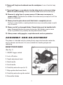
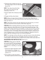
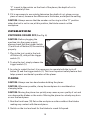
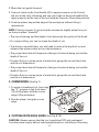
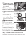
1
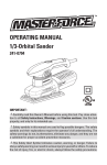
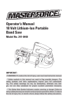
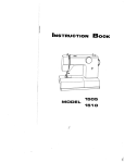
OPERATING MANUAL
Planer
241-0828
IMPORTANT :
Carefully read this Owner’s Manual before using this tool. Pay close attention to all Safety Instructions, Warnings, and Caution sections. Use this tool
properly, and only for its intended use.
Safety symbols in this manual are used to flag possible dangers. The safety
symbols and their explanations require the operator’s full understanding. The
safety warnings do not, by themselves, eliminate any danger, and they are not
a substitute for proper accident prevention measures.
This Safety Alert Symbol indicates caution, warning, or danger. Failure to
obey a safety warning can result in serious injury to yourself or others. To reduce
the risk of injury, fire, or electric shock, always follow the safety precautions.
TABLE OF CONTENTS
Specifications.................................................................................................. Page 2
Rules for Safe Operation............................................................................... Page 3
Assembly and adjustment............................................................................. Page 7
Operation.......................................................................................................... Page 10
Accessories..................................................................................................... Page 13
Maintenance................................................................................................... Page 13
Warranty........................................................................................................... Page 14
SPECIFICATIONS
Motor
120V 60Hz 6.0A
Single Speed
17, 000 RPM
Depth of cut range
0 to 5/64”
Width of cut:
3-1/4”
Weight:
7 LB 1 oz (3.2Kg)
SAFETY SYMBOLS FOR YOUR TOOL
The label on your tool may include the following symbols.
V...............................................................Volts
A...............................................................Amps
Hz.............................................................Hertz
W..............................................................Watts
min...........................................................Minutes
...........................................................Alternating Current
............................................................Direct Current
no ...........................................................No-load Speed
............................................................Class II construction
.../min.......................................................Revolutions or Strokes per minute
....................................................Indicates danger, warning caution. It means
attention! Your safety is involved.
2
RULES FOR SAFE OPERATION
KNOW THE TOOL
Read this operating manual and all the labels affixed to the angle grinder
carefully before using this tool. Keep this manual available for future
reference.
IMPORTANT
This tool should only be serviced by a qualified service technician.
READ ALL INSTRUCTIONS THOROUGHLY
GENERAL SAFETY RULES FOR ALL POWER TOOLS
WARNING!Read and understand all instructions. Failure to follow all instructions listed below may result in electric shock, fire and/or serious personal injury.
SAVE THESE INSTRUCTIONS
Work Area
eep your work area clean and well lit. Cluttered benches and dark
K
areas invite accidents.
o not operate power tools in explosive envirnments, such as in the
D
presence of flammable liquids, gases, or dust. Power tools create sparks
which may ignite the dust or fumes.
eep bystanders, children, and visitors away while operating a power
K
tool. Distractions can cause you to lose control.
Electrical Safety
ouble insulated tools are equipped with a polarized plug (one blade
D
is wider than the other.) This plug will fit in a polarized outlet only one
way. If the plug does not fit fully in the outlet, reverse the plug. If it
still does not fit, contact a qualified electrician
to install a polarized outlet. Do not change the
plug in any way. Double insulation eliminates
the need for the three wire grounded power cord
and grounded power supply system. void body contact with grounded surfaces such
A
as pipes, radiators, ranges and refrigerators.
There is an increased risk of electric shock if your
body is grounded.
3
120
V~
60H
z
on’t expose power tools to rain or wet conditions. Water entering a
D
power tool will increase the risk of electric shock.
o not abuse the cord. Never use the cord to carry the tools or pull
D
the plug from an outlet. Keep cord away from heat, oil, sharp edges or
moving parts. Replace damaged cords immediately. Damaged cords
increase the risk of electric shock.
hen operating a power tool outside, use an outdoor extension cord
W
marked “W-A” or “W”. These cords are rated for outdoor use and reduce
the risk of electric shock. The following table shows the correct size to
use, depending on cord length and nameplate amperage rating of the tool.
When in doubt, use the next heavier gauge. Always use UL and CSA listed
extension cords.
Recommended sizes of extension cords
Tool’s Ampere rating
Volts
0-6
6-10
10-12
12-16
120
V~
Total length of cord in feet
Cord size in A. W. G.(minimum)
25’
50’
100’
150’
18
16
16
14
18
16
14
12
16
16
14
12
14
12
Not Recommended
Personal Safety
tay alert, watch what you are doing and use common sense when
S
operating a power tool. Do not use tool while tired or under the influence
of drugs, alcohol, or medication. A moment of inattention while operating
power tools may result in serious personal injury.
ress properly. Do not wear loose clothing or jewelry. Contain long hair.
D
Keep your hair, clothing, and gloves away from moving parts. Loose
clothes, jewelry, or long hair can be caught in moving parts.
void accidental starting. Be sure switch is off before plugging in.
A
Carrying tools with your finger on the switch or plugging in tools that have
the switch on invites accidents.
emove adjusting keys or wrenches before turning the tool on. A wrench
R
or a key that is left attached to a rotating part of the tool may result in
personal injury.
o not overreach. Keep proper footing and balance at all times. Proper
D
footing and balance enables better control of the tool in unexpected
4
situations.
se safety equipment. Always wear eye protection. Dust mask, non-skid
U
safety shoes, hard hat, or hearing protection must be used for appropriate
conditions.
efore connecting the tool to a power source (receptacle, outlet, etc.), be
B
sure voltage supplied is the same as that specified on the nameplate of
the tool. A power source with voltage greater than that specified for the
tool can result in serious injury to the user – as well as damage to the tool.
Tool Use and Care
se clamps or other practical way to secure and support the workpiece
U
to a stable platform. Holding the work by hand or against your body is
unstable and may lead to loss of control.
o not force tool. Use the correct tool for your application. The correct
D
tool will do the job better and safer at the rate for which is designed.
o not use tool if switch does not turn it on or off. Any tool that cannot be
D
controlled with the switch is dangerous and must be repaired.
isconnect the plug from the power source before making any
D
adjustments, changing accessories, or storing the tool. Such preventive
safety measures reduce the risk of starting the tool accidentally.
tore idle tools out of reach of children and other untrained persons.
S
Tools are dangerous in the hands of untrained users.
aintain tools with care. Keep cutting tools sharp and clean. Properly
M
maintained tools, with sharp cutting edges are less likely to bind and are
easier to control.
heck for misalignment or binding of moving parts, breakage of parts,
C
and any other condition that may affect the tools operation. If damaged,
have the tool serviced before using. Many accidents are caused by poorly
maintained tools.
se only accessories that are recommended by the manufacturer for
U
your model. Accessories that may be suitable for one tool, may become
hazardous when used on another tool.
o not alter or misuse tool. These tools are precision built. Any alteration
D
or modification not specified is misuse and may result in a dangerous
condition.
5
Service
T ool service must be performed only by qualified repair personnel.
Service or maintenance performed by unqualified personnel could result
in a risk of injury.
hen servicing a tool, use only identical replacement parts. Follow
W
instructions in the Maintenance section of this manual. Use of
unauthorized parts or failure to follow Maintenance Instructions may
create a risk of electric shock or injury.
SPECIFIC SAFETY RULES FOR PLANER
1. H
old tool by insulated gripping surfaces when performing an operation
where the cutting tool may contact hidden wiring or its own cord. Contact
with a “live” wire will make exposed metal parts of the tool “live” and
shock the operator.
2. S
ecure the material being planed. Never hold it in your hand or across
legs. A small workpiece must be adequately secured so that the rotating
planer blades will not pick it up during forward motion of the planer.
Unstable support can cause the blades to bind, causing loss of control and
injury.
3. A
lways start the planer before the blade is in contact with the workpiece
and allow the blade to come to full speed. The tool can vibrate or chatter
if the blade speed is too slow at the beginning of the cut and could possibly
kickback.
4. C
heck the workpiece for nails. If there are nails, either remove or set
them well below the intended finished surface. If the planer blades strike
objects like nails they may cause the tool to kickback, and serious personal
injury may result.
5. N
ever leave the trigger locked “ON”. Unplug the planer before changing
accessories. Before plugging the tool in, check that the trigger lock is
“OFF”. Accidental start-ups may occur if the planer is plugged in while
changing an accessory.
6. A
fter changing blades, rotate the blade drum to make sure that blades
are not hitting any part of the blade-head housing and the blade-locking
screws are tight. Spinning blades could strike the tool housing and
damage the tool as well as possibly causing injury.
7. A
lways hold the tool firmly with both hands for maximum control.
6
8. N
ever pull the plane backward over the workpiece. Loss of control may
occur.
9. D
o not put fingers or any objects into the chip ejector or clean out chips
while the tool is running. Contact with the blade drum will cause injury.
10. Remove the plug from the power source if it becomes necessary to
remove chips. The blades are hidden from view and you may be cut if the
blade is contacted.
11. Never place the plane down until the blade is completely at rest.
Surface contact with a coasting blade drum may cause the plane to walk
out of control.
12. Never use dull or damaged blades. Sharp blades must be handled with
care. Damaged blades can snap during use. Dull blades require more
force to push the tool, possibly causing the blade to break.
13. Always wear safety goggles, respiration mask, and ear protection.
ASSEMBLY AND ADJUSTMENT
The planer is intended only for planing firmly supported wooden materials,
such as beams and boards. It is also suitable for beveling edges and
rabbeting.
KNOW YOUR PLANER
Fig. 1
(See Fig. 1)
1. ON/OFF trigger switch
2. Lock-off button
3. Depth-adjustment knob
4. Back handle
5. Front handle
6. Dust/chip extraction port (x 2)
7. Edge-guide attachment knob
8. Dust/chip extraction guide switch
9. Reversible blades
7
10. Blade barrel
11. Clamping screw
12. Adjustable front base
13. Fixed rear base
14. Edge guide
15. Bag adaptor
16. Dust bag
17. Wrench
18. Wrench storage sleeve
REMOVING OR INSTALLING PLANER BLADES
CAUTION: Always ensure that the tool is switched OFF and unplugged from
the power supply before installing or removing blades.
Your planer is fitted with reversible blades. Blades can be reversed when
one edge has become blunt. After
Fig. 2
both sides of the blades have been
used they should be discarded and
replaced with identical blades.
NOTE. These blades cannot be resharpened.
REMOVING A PLANER BLADE
1. U
sing the wrench (17), loosen the
three clamping screws (11) (See
Fig. 2).
Fig. 3
2. S
lide the planer blade (9) from the
slot in the blade barrel (10)
(See Fig. 3).
INSTALLING A PLANER BLADE
(See Fig. 4)
1.Use the other edge of the
reversible planer blade (9), or, if
dull, replace the blade.
8
4. S
lide the sharp blade face-up into Fig. 4
the blade-support block of the blade
barrel (10).
NOTE. The ridge along the blade
should be face away from the
clamping screws (11).
5. E venly tighten the clamping screws
(11).
6. R
epeat with the other blade.
NOTE: Always change the two blades at the same time, otherwise an
imbalance may occur and cause vibration and shorten the life of both the
blade and the tool.
NOTE: The blade position has been aligned at the manufactory, so do not
adjust the three inner hex screws on the blade supporter.
CAUTION: When installing blades, first clean out all chips and/or foreign
matter adhering to the blade barrel (10) and the blades themselves. Use
blades of the same dimensions and weight, or else the barrel will oscillate
and vibrate, causing poor planing action and tool breakdown. Tighten the
clamping screws (11) carefully when attaching the blades to the planer. A
loose clamping screw could be extremely dangerous. Regularly check to
ensure that the clamping screws are securely tightened.
NOTE: Your planing surface will end up rough and uneven unless the blades
are set properly and securely. The blades must be mounted so that the
cutting edge is absolutely level: parallel to the surface of the rear base (13).
ADJUSTING THE DEPTH OF CUT (See Fig. 5)
CAUTION: Always ensure that the
Fig. 5
tool is switched OFF and unplugged
from the power supply before making
adjustments or installing or removing
blades.
1. R
otate the depth-adjustment knob
(3) clockwise for a deeper cut
and counter-clockwise for a more
shallow cut.
2. T he numbers on the ring under
the depth-adjustment knob indicate the depth of cut. For example, when
9
“2” is next to the pointer on the front of the planer, the depth of cut is
approximately 2 mm.
3. If it is necessary to accurately determine the depth of cut, plane a scrap
piece of wood, measure the difference in thickness, and adjust the setting.
CAUTION: Always ensure that the number on the ring is at the “0” position
when the tool is not in use; at this position, the blade cannot cut the
workpiece.
OPERATION
SWITCHING ON AND OFF (See Fig. 6)
CAUTION: Before plugging the
Fig. 6
machine into the power supply,
always check that the trigger switch
(1) and lock-off button (2) are working
properly.
1. P
lug in the tool, push in the lockoff button (2), and pull the trigger
switch (1).
2. T o stop the tool, simply release the
trigger switch (1).
3. I n order to restart the tool, it is necessary to operate both the lock-off
button (2) and the trigger switch (1). This is an important safety feature that
helps prevent accidental operation of the planer.
PLANING
CAUTION: Always use two hands when holding the planer.
CAUTION: Wherever possible, clamp the workpiece to a workbench or
clamping table.
CAUTION: Moving the planer too quickly may cause a poor quality of cut and
can damage the blades or the motor. Moving the planer too slowly may burn
or mar the workpiece.
1. R
est the front base (12) flat on the workpiece surface without the blades
making any contact with the workpiece.
2. S
witch on the tool and wait for the blades to reach full speed.
10
3. M
ove the tool gently forward:
4. U
se your hand on the front handle [5], to apply pressure on the front of
the tool at the start of planing and use your hand on the back handle [4] to
apply pressure at the rear of the tool towards the end of the planing stroke.
5. P
ush the planer beyond the edge of the workpiece without tilting it
downwards.
NOTE: Planing is easier if you incline the workpiece slightly away from you
so that you plane “downhill”.
• The rate of planing and the depth of cut determine the quality of the finish.
• For rough cutting, you can increase the depth of cut.
• To achieve a smooth finish, you will need to reduce the depth of cut and
advance the planer slowly across the workpiece.
• The proper feed rate will depend on the type of material being cut and the
depth of the cut.
• Practice first on a scrap piece of material to gauge the correct feed rate
and the cut dimensions.
• The proper feed rate will depend on the type of material being cut and the
depth of the cut.
• Practice first on a scrap piece of material to gauge the correct feed rate
and the cut dimensions.
3. CHAMFERING (See Fig.7)
1. T o make a chamfered cut, first align Fig. 7
the “V” grooves in the front base
(12) of the planer with the corner
edge of the workpiece.
2. R
un the planer along the corner
edge.
450
4. CUTTING WITH EDGE GUIDE (See Fig. 8-10.)
CAUTION: Always ensure that the tool is switched OFF and unplugged
from the power supply before making adjustments or installing or removing
11
blades.
Fig. 8
1. T o fit the edge guide (14), remove
the edge guide attachment knob (7)
and slide the edge guide into the
planer, retighten the attachment
knob (7) (see Fig.8)
NOTE: Make sure that the two
notches in the fixing plate of the edge
guide are placed over the two lugs on
the planer body.
2. T o adjust cutting width, loosen the wing nut that secures the edge guide,
then position the slide to the desired width. Re-tighten the wing nut (See
Fig.9).
Fig. 9
• The scale on the edge guide
indicates the width.
• If it is necessary to change to a
precise width, plane a scrap piece
of wood, measure the distance and
adjust the setting as required (See
Fig. 10.)
5. DUST/CHIP EXTRACTION (See
Fig. 11)
Depending on which side of the
Fig. 10
planer you wish the dust/chips to flow,
connect the bag adaptor (15) to the
appropriate dust/chip extraction port
(6).
The bag adaptor (15) can be installed
to allow shavings to flow either to the
left or to the right of the workpiece.
Set the dust/chip extraction guide
switch (8) to point towards the desired
extraction port (6).
If desired, fit the dust bag (16) to the bag adaptor (15) so that the dust/
shavings are collected.
A workshop dust-extraction system or a household vacuum cleaner can be
12
connected to the dust/chip extraction Fig. 11
port (6) for the efficient removal of
dust and shavings.
6. INSTALL DUST BAG (See Fig. 12)
When planing, attach the dust bag to
the planer using the bag adaptor (15).
In addition, wear a suitable dust
mask, as there may be some residual
airborne dust particles in the area.
To clean the bag: Empty the dust bag
Fig. 12
by unzipping the lever lock located
on the bottom of the bag, and tap it
gently to remove dust. Occasionally
slip the bag off of the frame and turn
bag inside out. Brush dust off of the
lining using a soft brush.
ACCESSORIES
Edge guide 1pc
Wrench
1pc
Dust bag
1pc
Maintenance and Repair
Always ensure that the tool is switched OFF and unplugged from the power
supply before making any adjustments or carrying out any maintenance
procedures.
Keep the tool’s air vents unclogged and clean at all times. Using compressed
air may be the most effective cleaning method. Always wear safety goggles
when cleaning tools with compressed air.
Regularly check to see if any dust or foreign matter has entered the grates
near the motor and around the trigger switch. Use a soft brush to remove
accumulated dust.
If the body of the tool needs cleaning, wipe it with a soft cloth.
CAUTION: Water must never come into contact with the tool.
13
WARNING! Do not let brake fluids, gasoline, petroleum-based products,
penetrating oil, etc., come into contact with plastic parts. They contain chemicals that can damage, weaken, or destroy plastic.
WARNING! When servicing, use only identical replacement parts. The use
of any other parts may create a hazard or cause damage to the product.
WARNING! Use only accessories that are recommended for your model
by the manufacturer. Accessories that may be suitable for one tool may become hazardous when used on another tool.
WARNING! Maintain tools with care. Properly maintained tools work to
their best advantage and are easier to control.
WARNING! Check the power cord before each use. If it is damaged, replace it immediately. Never use a tool with a damaged cord.
WARNING! To ensure safety and reliability, all repairs should be performed
by a qualified service technician.
WARRANTY
If, during normal use, this MASTERFORCE™ power tool breaks or fails due
to a defect in material or workmanship within three years from the date of
original purchase, simply bring this tool and its sales receipt back to your
nearest Menards® retail store for a free equivalent replacement within those
three years.
The warranty:
(1) e xcludes expendable parts including but not limited to blades, bits, light
bulbs, and/or batteries;
(2) s hall be void if this tool is used for commercial or/and rental purposes;
and
(3) d oes not cover any losses, injuries to persons/properties, or costs. This
warranty does give you specific legal rights and you may have other
rights, which vary from state to state.
14