1
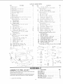
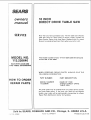
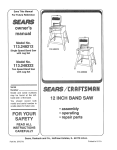
Save This Manual
For Future Reference
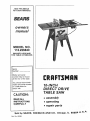
MODEL NO.
113.226640
SAW WITH LEGS AND
TWO TABLE EXTENSIONS
Serial
Number
Model and serial
number may be found
at the rear of the base.
You should record both
model and serial number
in a safe place for
future use.
IO-INCH
DIRECT DRIVE
TABLE SA W
CAUTION:
• assembly
READ ALL
INSTRUCTIONS
CAREFULLY
Sold by SEARS,
Part No. 62969
• operating
= repair parts
ROEBUCK
AND
CO.,
Chicago,
IL. 60684
U.S.A-
FULL ONE YEAR WARRANTY'
ON CRAFTSMAN
TABLE
_f w_thm one year from the date of purchase, this Craftsman
Table
materia_ or workmanship.
Sears will repair it, free of charge.
WARRANTY
SERVICE
IS AVAILABLE
BY SIMPLY
SERVICE CENTER/DEPARTMENT
THROUGHOUT
This
warranty
applies
only
while
This warranty
gives you specific
from state to state.
SEARS,
u j j
GENERAL
,
ROEBUCK
AND
this
product
legal
rights,
CO..
...... _J_ILL--LJJJ-._.J.,--__
Dept.
,
SAFETY
,
2. GROUND
3, KEEP
ALL TOOLS
GUARDS
in working
alignment.
and in proper
4, REMOVE ADJUSTING
AND WRENCHES
adjustment
and
KEYS
Form habit of checking
to see that keys
adjusting
wrenches
are removed
from
before turning it on,
5. KEEP WORK AREA CLEAN
Cluttered
areas and benches
Floor must
not be slippery
sawdust.
and
toot
6, AVOID DANGEROUS
ENVIRONMENT
Don't use power tools in damp or wet locations
or expose them to rain
Keep work area well
lighted,
Provide
adequate
surrounding
work
space
7, KEEP CHILDREN
AWAY
AH visitors should
work area.
8, MAKE
WORKSHOP
be kept a safe distance
from
CH!LD-PROOF
....... w_th padlocks,
master
removing
starter keys
9. DON'T FORCE TOOL
Jt witl do the job better
which _t was designed.
10. USE RIGHT TOOL
698/731A,
Sears
Tower,
switches,
or
by
and safer at the rate for
Don't force toot or attachment
to do a job _t was
not designed
for.
11, WEAR PROPER APPAREL
Do not wear loose clothing,
gloves, neckties or
iewelry
(rings, wrist watches)
to get caught in
moving
parts.
Nonslip
footwear
is
recommended.
Wear protective
hair covering to
contain
long hair. Roll tong sleeves above the
e|bow.
12. USE SAFETY GOGGLES
(Head Protection)
Wear Safety goggles
(mL_st comply
w_th ANSI
in
SEARS
States.
Chicago,
rights
which
vary
IL 60684
,
-
FOR POWER
..
,
_
....
TOOLS
Z87,1) at alJ times. Everyday
eyeglasses
only
have impact
resistant
lenses,
they are NOT
safety glasses. Also. use face or dust mask if
cutting
operation
is dusty, and ear protectors
(plugs or muffs) during
extended
periods
of
operation,
13. SECURE WORK
Use clamps
or a vise to hold
work
when
practical.
It's safer than using your hand, frees
both hands to operate toot.
14. DON'T
OVERREACH
footing
and balance
at all times.
15. MAINTAIN
TOOLS WITH CARE
Keep tools sharp and clean for best and safest
performance.
Follow instructions
for lubricating
and changing
accessories
16. DISCONNECT
TOOLS
before servicing;
when changing
such as blades, bits, cutters, etc.
17. AVOID
invite accidents
due to wax or
THE NEAREST
STATES.
is in use in the United
Keep proper
IN PLACE
order,
CONTACTING
THE UNITED
mNSTRUCTIONS
This too_ as equipped
with an approved
3conductor
cord and a 3-prong grounding
type
ptug to fit the proper grounding
type receotacle
The green
conductor
in the cord
is the
grounding
w_re Never connect the green wire to
a live terminal.
Saw fails due to a defect
and you may also have other
,
1. KNOW YOUR POWER TOOL
Read and understand
the owner's manual and
labels affixed to the tool. Learn its application
and fimitafions
as well as the specHic potential
hazards peculiar to this tool.
SAW
ACCIDENTAL
Make sure switch
plugging
in
accessories
STARTING
is in "OFF"
position
before
18. USE RECOMMENDED
ACCESSORIES
Consult the owner's manual for recommended
accessories.
Follow
the instructions
that
accon_pany
the
accessories.
The
use
of
improper
accessories
may cause hazards.
19. NEVER STAND ON TOOL
Serious injury could occur if the tool is tipped or
if the cutting
tool is accidentally
contacted.
Do not store materials
above or near the tool
such that it is necessary to stand on the tool to
reach them.
20. CHECK
DAMAGED
PARTS
Before further
use of the tool. a guard or other
part
that is damaged
should
be carefully
checked
to ensure that it will operate properly
and perform
its intended
function.
Check for
alignment
of moving parts
binding
of moving
parts, breakage
of parts, mounting,
and any
other conditions
that may affect its operation.
A
guard or other part that is damaged
should be
properly
repaired or replaced.
21. DIRECTION
OF FEED
Feed work into a blade or cutter against
the
direction
of rotation of the blade or cutter only,
22. NEVER LEAVE
UNATTENDED
TOOL
RUNNING
Turn Dower off, Don't _eave too_ until
a complete
stop,
it comes
to
ADDiTiONAL
SAFETY
iNSTRUCTiONS
WARNING:
FOR YOUR OWN SAFETY,
DO NOT
OPERATE YOUR SAW UNTIL iT IS COMPLETELY
ASSEMBLED
AND iNSTALLED
ACCORDING
TO
THE INSTRUCTIONS
... AND UNTIL YOU HAVE
READ AND UNDERSTAND
THE FOLLOWING.
1. GENERAL
SAFETY
iNSTRUCTIONS
POWER TOOLS o.. SEE PAGE 2
2. GETTING
20.
3. BASIC
TO KNOW
YOUR SAW...SEE
SAW OPERATION...
SEE PAGE
B
FOR
PAGE
23.
C
4. MAINTENANCE...
SEE PAGE 32.
5. STABILITY
OF SAW
if there is any tendency for the saw to tip over or
move during certain cutting operations
such as
cutting
extremely
large heavy panels or long
heavy boards
the saw should be bolted down
If you attach any kind of table extensions
over
24" wide to either end of the saw, make sure you
either bo_t the saw to the bench or floor as
appropriate,
or support
the outer end of the
extension
from
the
bench
or floor
as
appropriate
6. LOCATION
The saw should
be positioned
so neither the
operator nor a causal observer is forced to stand
in line with the saw blade
D,
E
7. KICKBACKS
A "KICKBACK"
occurs
during
a rip-type
operation
when a part or all of the workpiece
is
thrown back violently
toward the operator
Keep your face and body to one side of the
sawblade
out of line with a possible "Kickback'"
Kickbacks
-- and possible
injury from them -can usually be avoided by:
A Maintaining
the rip fence parallel
to the
sawbtade
B Keeping
the sawblade
sharp
Replace
or
sharpen
antikickback
pawls when points
become dull
C Keeping
sawblade
guard,
spreader,
and
antikickback
pawls in place and operating
properly
The spreader must be in alignment
with the sawblade and the pawls must stop a
kickback
once it has started
Check their action before ripping.
D, NOT ripping work that is twisted or warped
or does not have a straight
edge to guide
along the rip fence,
E, NOT releasing work until you have pushed it
aH the way past the sawblade.
F, Using a push stick for ripping widths of 2 to 6
in., and an auxiliary
fence and push block for
ripping
widths
narrower
than 2 in. (See
"Basic Saw Operation
Using The Rip Fence"
section.)
G. NOT
confining
the cut-off
piece
when
ripping or cross-cutting,
H, When ripping
apply the feed force to the
section of the workpiece
between
the saw
blade and the rip fence,
FOR TABLE
SAWS
operating
immediately
until the particular
part is proper_y repaired or replaced
Small loose pieces of wood or other obiects
that contact
the rear of the revolving
b_ade
can be thrown
back at the operator
at
excessive speed This can usuaIiy be avoided
by keeping the guard and spreader in p}ace
for
ai_ thru-sawing
operations
(sawing
entirely thru the work) AND by removing
all
loose pieces from the table with a long st_ck
of wood IMMEDIATELY
after they are cut off
Use extra caution when the guard assembly
is removed for resawing, dadoing, rabbeting,
or molding
-- replace the guard as soon as
that operation
is completed.
For rip or rip-type cuts, the following
end )f a
workpiece
to which a push stick or push
board
is
applied
must
be
square
(perpendicular
to the fence) in order that
feed pressure
applied
to the workpiece
by
the push stick or block does not cause the
workpiece
to come away from the fence, and
possibly
cause a kickback.
During rip and rtp type cuts, the workp_ece
must be held down on the tabJe and against
the fence with a push stick, push b_ock or
featherboards.
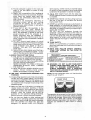
A featherboard
is made of
solid lumber per sketch.
&
........
i
F
G.
H.
f
J
K
L
8. PROTECTION:
EYES, HANDS,
FACE, EARS,
BODY
A, If any part of your saw is malfunctioning,
has
been damaged
or broken
, . . such as the
motor switch, or other operating
control,
a
safety device or the power cord . .. cease
M
3
K &;_:{:
&_-OLI '
I
.................... J ]
NEVER turn the saw "ON'" before clearing
the table of all tools_ wood scraps,
etc.,
except the workpiece
and re!ated feed or
support dewces for the operation
planned.
NEVER place your face or body tn tine with
the cutting toot,
NEVER place your fingers or hands _n the
path of the sawblade
or other cuthng tool.
NEVER reach in back of the cutting tool w_th
either hand to hold down or support
the
workp_ece,
remove wood scraps, or for any
other reason Avoid awkward operations
ana
hand posihons
where a sudden
shp cou}d
cause
fingers
or hand
to move
into
a
sawblade
or other cutting
tool
DO NOT perform layout assembly
or setup
work on the table ,while the cutting
too! is
rotating
DO
NOT
perform
any
operation
"FREEHAND"
-- always
use either the np
fence or the miter gauge to position
and
guide the work
NEVER use the rip fence when crosscutting
or the miter gauge when ripping
DO NOT
use the rip fence as a _ength stop
Never hold onto or touch the "free end" of the
workpiece
or a "free piece' that is cut off
while power is "ON" and/or the sawblade _s
rotating
Shut "OFF"
the saw and d_sconnect
the
power cord when removing
the table insert
changing
the cutting
too|
remowng
or
replacing
the blade
_uard.
or ma_mg
adjustments.
N
O.
P.
Q.
R.
Provide adequate
support
to the rear and
sides of the saw table for wider or long
workpieces.
Plastic
and composition
(like hardboard)
materials
may be cut on your saw, However,
since
these
are usually
quite
hard
and
slippery,
the antikickback
pawls may not
stop a kickback.
Therefore,
be especially
attentive
to
following
proper
set-up
and
cutting
procedures
for ripping.
Do not stand, or
permit anyone else to stand, in line with a
potential
kickback.
If you stall or jam the sawblade
in the
workpiece,
turn
saw "OFF",
remove
the
workpiece
from the sawblade
and check to
see if the sawblade
is parallel to the miter
gauge
grooves
and if the spreader
_s in
proper
alignment
with
the sawblade.
If
ripping
at the time, check to see if the rip
fence is parallel with the sawblade.
Readjust
as indicated.
DO NOT remove
small
pieces of cut-off
material that may become trapped inside the
blade guard while the saw is running.
This
could
endanger
your
hands
or cause
a
kickback.
Turn saw *OFF
and wait until
blade stops.
Use extra care when ripping wood that has a
twisted g rain or is twisted or bowed
it may
rock on the table and/or pinch the sawblade.
9. KNOW YOUR CUTTING
TOOLS
A. Dull, gummy, orJmproperlysharpened
orset
cutting
tools can cause material to stick, jam,
stall the saw or kickback
at the operator.
Minimize
potential
injury by proper cutting
tool and machine maintenance.
NEVER ATTEMPT
TO FREE A STALLED
SAWBLADE
WITHOUT
FIRST TURNING
THE SAW OFF.
B. Never use grinding
wheels, abrasive
cut-off
wheels,
friction
wheels
(metal
slitting
blades) wire wheels or buffing wheels.
10. USE ONLY
THiS SAW.
ACCESSORIES
DESIGNED
FOR
when ripping, use the maximum diameter blade
for which the saw is designed, since under these
conditions the spreader is nearest the blade.
14. Adjust table inserts flush with the table top.
NEVER operate the saw unless the proper insert
is installed.
15. NEVER feed material into the cutting tool from
the rear of the saw. An accident and serious
injury could result.
17. NEVER use another person as a substitute for a
table extension, or as additional support for a
workpiece that is longer or wider than the basic
saw table, or to assist in feeding or supporting or
pulling the workpiece.
DO NOT pull the workpiece
through
the
sawblade - position your body at the nose (infeed) side of the guard: start and complete the
cut from the same side This will require added
table support for long or wide workpeices that
extend beyond the length or width of the saw
table.
18, THINK SAFETY.
Safety is a combination
of operator
common
sense and alertness
at all times when the saw is
being used.
19. NOTE
TIONS
YOUR
AND
THAT
SAW.
I DANGER
READ
1.
WEAR
AND
SAFETy
SE SAWBLADE
•, KEEP
HANDS
4
USE
FOLLOW
APPEAR
OWNERS
MANUAL
BEFORE
5.
HOW
FOR OF"THRU.SAWING,'
OUT GUARD
OF
PATH
SAWBLADE,
A "PUSH.STICK"
WHEN
USE
iNSTRUCFRONT
OF
] FORYOUR OWN SAFETY:
UNDERSTAND
GOGGLES
WARNING:
SAFETY
ON THE
6.
7
KNOW
TO
OPERATING
AVOID
MACHINE.
"KICKBACKS._
DO NOT REACH
PERFORMAROUND
OPERATIONS
NEVER
OR OVER "FREEHAND."
SAWRLADE
REQUIRED.
120 VOLT
15 AMP
8RANCH
CIRCUIT
AND
USE
15 AMP.
TIME
DELAY
FUSE
20. WARNING: DO NOT ALLOW FAMiLiARiTY
(GAINED FROM FREQUENT USE OF YOUR
SAW) TO BECOME
COMMONPLACE.
ALWAYS REMEMBER THAT A CARELESS
FRACTION OF A SECOND IS SUFFiCiENT TO
iNFLiCT SEVERE iNJURY.
NOTE: Do not overtighten
wrench to just "snug" it.
arbor nut. Use the arbor
11. Crosscutting
operations
are more convenientJy
worked
and with greater safety if an auxiliary
wood facing isattached
tothe mitergauge
using
the holes provided.
However,
the facing must
not interfere with the proper functioning
of the
sawblade
guard ....
12. Make sure the top of the arbor or cutting
tool
rotates toward
you when standing
in normal
operating
position.
Also make sure the cutting
tool, arbor collars and arbor nut are installed
properly.
Keep the cutting
tool
as low
as
possible
for the operation
being performed.
Keep all guards in place whenever
possible.
The operation of any power tool can result in foreign
bjects being thrown into the eyes, which can result
13. Do not use any blade
marked for an operating
RPM. Never use a cutting
than the diameter
for
designed.
For greatest
in severe eye damage. Always wear safety goggles
complying
with ANSI Z87.I
(shown
on Package)
before commencing
power tool operation.
Safety
Goggles
are available
at Sears retail or catalog
stores.
or other cutting
tool
speed less than 3450
toot larger in diameter
which
the saw was
safety
and efficiency
MOTOR
$PECIFmCATION$
AND
ELECTRICAL
This saw is designed to use a 3450 RPM motor only.
Do not use any motor that runs faster than 3450
RPM. It is wired for operation on 110-120 volts, 60
Hz., Alternating
current.
IT MUST NOT BE
CONVERTED TO OPERATE ON 230 VOLTS.
This
type
plug requires a mating
outlet as shown.
It is recommended
electrician
replace
properly
grounded
THE STARTING
RELAY iN THiS SWITCH HOUSING
IS A GRAVITY
SENSiTiVE
TYPE. NEVER TURN
THE POWER ON UNTIL THE SWUTCH HOUSING
HAS BEEN ASSEMBLED
ON THE FRONT FENCE
BAR AND THE SAW iS UPRIGHT
IN SAWING
POSiTiON.
grounded
that
you have a quaHfliec
the TWO prong outlet
wit_-_
THREE prong outlet.
A temporary
adapter as shown below is avai!abto
fo
connecting
plugs to 2-prong receptacles.
The g roe_
grounding
lug extending
from the adapter must b,,
connected
to a permanent
ground
such as to
properly
grounded
outlet box.
CONNECTING TO POWER SOURCE OUTLET
This saw must be grounded while in use to protect
the operator from electrical shock.
If power cord is worn or cut, or damaged in anyway,
have it replaced immediately.
If your saw is for use on less than 150 volts it has a
plug that looks like below.
A temporary
adapter as illustrated
is available
fo
connecting
plugs
to 2-prong
receptacles.
Tih_
temporary
adapter
should
be used on;y unt_
properly
grounded
outlet
can be installed
by
qualified
electrician.
GROUNDING
LUG
PLUG
__
P,OG
3-PRONG
_
_/_
I "_L_-._/tl
L---._---
MAKE
SURE
THiS
iS
,NOWN
GROUND
CONNECTED
/
\
GROUNDING
3-COnductor
If the outlet you are planning to use for this saw ;
_S O1
the two prong type DO NOT REMOVE OR ALT_
THE GROUNDING
PRONG IN ANY MANNER
Us_
an adapter
as shown
and always
connect
t_
grounding
lug to a known ground.
WARNmNG
3-PRONG
REQUIREMENTS
TO
A
"EOE.,ACLE
ADAPTER
PRONG
WARNING:
THE GREEN
GROUNDING
LUC
EXTENDING
FROM THE ADAPTER MUST
BE
CONNECTED
TO A PERMANENT
GROUNE
SUCH AS TO A PROPERLY GROUNDED OUTLEI
BOX. NOT ALL OUTLET BOXES ARE PROPERL_
GROUNDED.
IPERLY
GROUNDED
3-PRONG
OUTLET
Plug power cord of fully assembled saw into 110120V properly grounded type outlet protected by a
15-amp. time delay or Circuit-Saver fuse or circuit
breaker.
iF YOUR ARE NOT SURE THAT YOUR OUTLET iS
PROPERLY GROUNDED, HAVE iT CHECKED BY
A QUALIFIED ELECTRiCiAN.
If you are not sure that your outlet box is proper_,
grounded,
have it checked by a qualified electrician
NOTE: The adapter illustrated
is for use only if yo_
already
have
a properly
grounded
2-pror_
receptacle.
WARNING:
DO NOT PERMIT
FINGERS
TO
TOUCH THE TERMINALS
OF PLUG WHEN
iNSTALLiNG OR REMOVING THE PLUG TO OR
FROM THE OUTLET.
WARNING: iF NOT PROPERLY GROUNDED THiS
POWER TOOL CAN iNCUR THE POTENTIAL
HAZARD OF ELECTRICAL SHOCK PARTICULARLY WHEN USED IN DAMP LOCATIONS, iN
PROXIMITY TO PLUMBING, OR OUT OF DOORS.
iF AN ELECTRICAL SHOCK OCCURS THERE IS
THE POTENTIAL OF A SECONDARY HAZARD
SUCH AS YOUR HANDS CONTACTING
THE
SAWBLA DE.
The use of any extension
cord will cause some ios
of power. To keep this to a minimum
and to prever_
over-heating
and motor
burn-out,
use the tabh
below to determine
the minimum
wire size (AW. G
extension
cord. Use only 3 wire extension
DOra
which have 3 prong grounding
type plugs and
3
pole receptacles
which will accept the plug on th4
saw.
The motor must rotate COUNTERCLOCKW_S
when viewed from the shaft end.
1 H.P. MOTOR 1t0-120V
Extension Cord Length
Wire Size A.W.G.
14
Up to 50 Ft.................
12
50 to 100 Ft ................
This saw is equipped with a 3-conductor cord and
grounding type plug which has a grounding prong,
approved by Underwriters'
Laboratories and the
Canadian Standards
Association.
The ground
conductor has a green lug and is attached to the tool
housing at one end and to the ground prong in the
attachment plug at the other end.
100 - 200 Ft ................
200 - 400 Ft .................
5
10
8
CONTENTS
WARRANTY
.................................
2
GENERAL
SAFETY INSTRUCTION
FOR POWER TOOLS
....................
2
ADDITIONAL
SAFETY INSTRUCTIONS
FOR TABLE SAWS
......................
3
MOTOR SPECIF_CATIONS
AND ELECTRICAL
REQUIREMENTS
........................
5
UNPACKING
AND CHECKING
CONTENTS
. .. 6
Tools Needed ..............................
6
List o1 Loose Parts .........................
7
ASSEMBLY
..................................
7
Assembling
Steel Legs
.....................
7
Mounting
Saw .............................
8
Installing
Handwheels
......................
8
Checking
Table Insert ......................
9
Heeling Adjustment
of Parallelism
of
Sawbtade
to Miter Gauge Groove
.........
9
Btade Tilt or Squareness
of Blade to Table
10
Btade Bevatton
...........................
12
T Ht and Elevation
Mechanism
..............
12
Attaching
Table Extensions
................
12
installing
Rip Fence Guide Bars and Switch
13
Aligmng
Rip Fence ........................
16
Adjusting
Rip Scale Indicator
..............
!7
Installing
Blade Guard
....................
18
Adjusting
Miter Gauge
....................
20
GETTING
TO KNOW YOUR SAW
...........
20
On-,Off Switch
............................
20
Elevation
Handwheel
......................
21
Till Handwheel
...........................
21
Rip Fence
................................
2t
UNPACKING
TOOLS
Miter Gauge
..............................
B_ade Guard
..............................
Table Insert
..............................
Removing
and Installing
Sawblade
.........
Exacti-Cut
................................
BASIC SAW OPERATION
USING THE MITER
GAUGE
................................
Work Helpers
.............................
Using the Miter Gauge
....................
Crosscutting
...............................
Repetitive
Cutting
.........................
Miter Cutting
.............................
Bevel Crosscutting
........................
Compound
Miter Cutting
..................
BAStC SAW OPERATION
USING ]HE RIP
FENCE .................................
Ripping
..................................
Bevel Ripping
.............................
Cutting
Panels
............................
Ploughing
and Molding
...................
Resawing
.................................
Rabbeting
................................
Dadoing
..................................
Molding
Cutting
..........................
Using Featherboards
......................
MOTOR
....................................
MAINTENANCE
............................
LUBRICATION
.............................
RECOMMENDED
ACCESSORIES
...........
TROUBLE
SHOOTING
......................
REPAIR PARTS
.............................
AND CHECKING
21
22
22
22
22
23
23
24
24
25
26
26
26
26
27
27
29
29
30
30
30
31
31
31
32
32
33
33
36
CONTENTS
NEEDED
COMBINATION
Medium
Small
#2
Serewdrlve
MUST
STRAIGHT
3/4" THICK.
r
DRAW LIGHT
BOARD
ALONG
Screwdriver
Phillips
SQUARE
LINE
THIS
ON
EDGE,
BE
BE TRUE,
EDGE
THIS
PERFECTLY
OF BOARD
EDGE
MUST
STRAIGHT.
_-,
Screwdriver
Pliers
"%y
Combination
Square
3/8
in,
7/16
in.
1/2
in.
9/16
In.
SHOULD
BE NO GAP
HERE WHEN
SQUARE
OVER IN DOTTED
OR OVERLAP
IS FLIPPED
POSITION.
3/4 in.
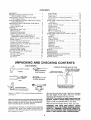
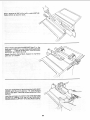
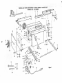
Model 1 t3.226640
one carton.
Table Saw is shipped
complete
in
Remove the protective
oi! that is applied to the table
top and edges
of the table.
Use any ordinary
household
type grease and spot remover.
CAUTION: To avoid fire or health hazard never use
gasoline, naptha or similar highly volatile solvents.
Separate all parts from packing materials and check
each one with the illustration
and the list of Loose
Parts to make certain all items are accounted
for,
before discarding
any packing
material.
Apply
Wipe
a coat of automobile
all parts
thoroughly
wax to the table.
with a clean,
dry cloth.
WARNING:
FOR YOUR OWN SAFETY,
NEVER
CONNECT
PLUG TO POWER SOURCE OUTLET
UNTIL ALL ASSEMBLY
STEPS ARE COMPLETE,
AND YOU HAVE READ AND UNDERSTAND
THE
SAFETY AND OPERATIONAL
INSTRUCTIONS.
If any parts are missing, do not attempt to assemble
the table saw, plug in the power cord or turn the
switch on until the missing parts are obtained
and
are installed
correctly.
6
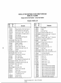
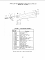
LIST
Him
Par_Nam_
A Miter Gause ............................
B Ris Fen:e" ...........................
C Bt_'_deG,ua_da_!d Sp_eade_ , ..............
D HamJwhee! ..............................
E Rip Fe__ceGuide Ba_, _,:'a_ . ...........
F Rip Fe_ce Guide Sa,_RoA ...............
G Exte__s;o_.Table ...........................
H Leg ......................................
J Stiffe;_e_ Side ...........................
K Stiffener E_d ...........................
L R,p .... ct;Gu(.
Bar wKh Ri_)Sc_i_: F_o_!)
M 0wrsers Mam._ai
BaG of Loose Pa_ts (Pa_t No 62982) .....
Consisting o!:
N
I
S ............................
fl
Wr e_ch,Sl,a
P
W_enck, A_bo_ . .....................
LL Pointer, Bevel ........................
'Baq oI Loose Pots (Pa_t No ,.7.;:7_
C,onsislmg of:
Q
Foot Leve!i,'_(] .....................
R
Nut. Hex Jam i 2-13 .................
S
Nut Hex 1i4-20 ....................
lJ420x
'[
Screw. r _u_>SHd
......
""
5/8 ........
U
Lockwashe_. Ex!e_m:d 114 ............
OF LOOSE
Qty.
I
!
i
2
I
2
4
2
2
!
1
1
I
1
,4
8
24
_.
24
24
I
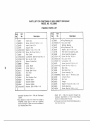
PARTS
Item
[tD
NuL Sa
Part Name
1/4-29 .................
Qty.
2
EE
IF:
B_cket, Co_e,' Su;}po_t ............
B_a(iket. CoirIei StlffemI/ , ..............
B_,, ,-_,'I '-y",', P_;_: iPa t .... 61;>qAah
Oo,"_sistin_
I Ol
, o Nu...........
I_, Nut, jam 5/16-t8 ....................
S
Nut, H_x !/4,.20 ...................
]
Sc_ew.T_ussHd !/4-20x ! .........
U
Lockwastie_, Exte_nai !/4 .............
U
Lockwashe_, Exte_p,a! 5/16 ............
GG ScTew. Hex 5/I6.18 x t-1/4 ............
HH Washe_, 1t/32x 11i16× I 16 ........
HH Washe_. 17164 x 3/4 x t/16 ...........
*B_!] of Loose Parts (Pa,_tNo 62981) .....
Coi_sJstti}{:
I Of;
R
Nut. Hex 3am 5/16-!8 .................
S
Nut. !l<x I/4-20 ....................
U
Lockwashe_. Externa_ 5/t6 ........
GG Screw. Hex 5/!6-t8 x !12
..........
GG Sc_,.'w. Hex 5i16. t8 x 1 .............
HH "4._'ash_;,,
............ I)'i64 x 9 / 16 x 3'64 .............
HH Washe_, 2t/64 x 5/8 x t/16 ...........
jj
Space_, Fence Guide Bar , ...........
*Bai of Loose Parts (Part No. 507421)
bo[tsisfing of:
S
Nut Hex 5/16-18 ....................
S
Nut, Hex 1!4-20 ....................
T
Screw, Truss Hd. 1!4-20 x 5i8 .........
U
Lockwasher, External 5/16 ............
U
Lockwasher, External t/4 .............
AA Screw, PanHd, Type:T'No.
8x3/8
...
GG Screw, Hex Hd. 51t6- i8 x 3t4 ..........
HH Washer, 17!64 x 5/8 x t/t6
..........
KK Nut, Self Threading .................
P
"_
i
3
8
8
8
3
3
3
2
1
'2
2
4
2
2
,4
4
2
2
4
4
4
8
!
2
8
2
"These Bags are in Bag of Loose Parts No, 62982
' o
V ............
li
'_....
" --" HH
k::;_
(
;;,
w.............. '..:........
> .cc
t:
.....
<,;
-"
-.
X .......
_
......
;'
<--DD
:',,,,:..._ J J
"k
........
::::.
......
<
,....,
{ _:>"
f',-::i..............
FF
....
£:; _i:"f }----K
",.c_/_
I'(
,.-Q
,._2i"
M
U
*<{::!":1"
" .........
£
ij
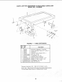
ASSEMBLY
ASSEMBLY
OF STEEL
LEG
SET
Assembly is best done in the location where the saw
witl be stationed and used.
If Ine saw you purchased is furnished with a leg set
fo!low the instructions below for easy assembly
1. Locate
the following:
Description
Steel Legs ................................
Side Stiffeners ............................
End Stiffeners ............................
Leveling Feet .............................
Hex Nuts, 1/2-13 .........................
Truss Head Screws, 1/4-20 x 5/8" , ........
Hex Nuts, 1/4-20 .........................
I/4 I.D. External Lockwashers .............
Qty.
4
2
2
4
8
24
24
24
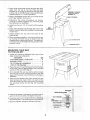
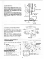
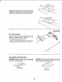
2. Insert three truss head screws through the three
holes near the top of one leg. Place the side
stiffener up to the leg as shown so that the three
screws line up with the holes in the side stiffeners
marked with an "X" in the illustration
/
/
J
3. Place a Iockwasher and a hex nut on each screw
and finger tighten the hex nut.
ASSEMBLE
SCREWS
THROUGH
HOLES
MARKED
"X"
SIDE
STOFFENER
4. Following
the same procedure
as above.
continue to fasten together the remaining legs
and stiffeners as illustrated.
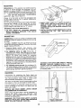
5. Install
feet.
one hex nut, 1/2-13.
on each of the leveling
\
END
STIFFENER
6. Insert each leveling foot through
the hole in the
bottom of each leg so the leveling foot pad rests
on the floor.
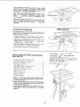
7, Install another
leveling feet.
hex
nut
1/2-13
on
each
\
of the
8. After complete
assembly,
you may level the saw
by moving
the lower nut up or down along the
threaded
stud of each leveling foot. The upper nut
ts used to lock the leveling foot into position when
the saw is level.
MOUNTING
YOUR
TO THE LEG SET
\
IN. HEX
SAW
1, Locate the following
hardware
bags containing
loose parts
from
one of the
Description
Truss Head Screws, 1/4-20 x 5/8 ...........
Hex Nuts, 1/4-20 ..........................
1/4 I.D. External Lockwashers
.............
11/32 I.D. Flat Washers
....................
Qty
4
4
4
8
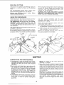
2. Place the saw on top of the leg set so that the base
of the saw lines up approximately
even with the
outline of the top of the leg set.
3. From beneath the saw you wil be able to locate
and line up the four mounting
holes of the saw
base with the proper mounting
holes in the leg set
assembly.
/
/
/
/
!
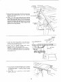
4. Place one flat washer onto each of the four hex
head screws
and insert them into each of the
mounting
holes. Be sure the screws go through
the saw base holes and the leg set mounting
holes
SAW
BASE
TRUSS HEAD SCREW _""'_1
1_
I
5. Install a flat washer, Iockwasher.
and a hex nut on
each of the four screws and tighten securely.
6. Level the saw to your requirements
by adjusting
the leveling feet. Lock leveling
feet into position.
7. Securely
tighten
all leg set screws
#FENER--,
and nuts.
II
U
8
NUTS
mNSTALLING BEVEL POINTER
HANDWHEELS
AND
Locate the following parts
Bevel Pointer ...............................
Screw, 8-32 x 3/8 ...........................
Handwheels ................................
Screw, Phillips 10-32 x 3/4 ..................
Lockwashers, 3/16 I.D. External .............
1
1
2
2
2
LOCKWASHER
1. Fasten bevel pointer to cradae assembly with 8-32
x 3/4 in screw, as shown. Adjustment
of the
pointer may be necessary later.
2. Push handwheels onto shafts as shown and
fasten each with a 10-32 x 3/4 in. screw and
Iockwasher.
LOCKWASHER
SCREW
BEVEL
SCREW
T
POINTER
_
TILT
ELEVATION
HANDWHEEL
//
SCREW
/
HANDWHEEL
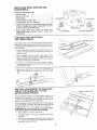
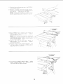
CHECKING
AND ADJUSTmNG
THE TABLE iNSERT
The table insert must be flush with the surface of the
saw table to keep the workpiece
from hanging
up or
binding with the sawblade as the workpiece
is cut by
the sawb ade.
1. Lower sawblade
beneath
check to be sure the screw
place is snug.
STRAIGHT
the table insert and
fastening
the insert in
EDGE
2. Use a straight
edge to check
near each of the
eight leveling
tab positions
to determine
if the
insert is flush with the surface of the saw table at
all eight beveling tab positions.
3. If insert is not flush with table surface
loosen
insert fastening
screw and pull insert forward
to
lift from saw table.
\
4. Bend tabs with pliers or tap with a hammer as
required
to make the insert flush with the table
\
top.
HEEUNG
ADJUSTMENT
iSM OF THE SAWBLADE
MITER
GAUGE
GROOVE
OR PARALLELTO THE
MARK
The workpiece
being cut must always move in a
straight
line parallel
to the sawblade.
Therefore.
both the miter gauge groove and the rip fence must
always be parallel with the sawblade.
If the sawblade
is NOT parallel with the miter gauge
groove and the rip fence, the workpiece
will bind at
one end of the cut. This is known as "heeling".
WARNING:
For your own safety, turn switch
and remove plug from power source outlet.
1. Raise
blade
to highest
"OFF"
elevation.
2. Lift blade guard, if already installed,
to highest
position.
3. Use chalk or another suitable marker to mark an
"X" on one of the teeth of the sawblade
which is
naturally
bent to the left.
9
"X" ON
,/
TOOTH
5. Rotate the sawblade
so that the "X" on the tooth
is now visible at the rear of the saw.
4. Using an accurate combination square, placethe
head of the square in the miter gauge groove and
adjust the ruler blade of the square so that the end
of the blade just touches the side of thetooth you
marked on the sawblade. Remember to keep the
head of the square flush against the miter gauge
groove.
6. Move the combination
square to the rear of the
saw and the end of the square blade should just
touch the marked tooth the same as it did at the
front of the sawblade.
7. If sawblade does not appear to be parallel with
the miter gauge groove you must adjust the
position of the sawblade by loosening the four
adjustment locking screws about 1/2 turn.
8. Loosen two pan head screws, 10-32, on the rear
skirt of the table about 1/2 turn.
1,
]
SETSCREW
9. The mechanism
under the table can now be
moved sideways
from above by covering
the
sawblade
with a piece of cardboard
and shifting
the blade to the right or left as required.
10. After shifting
the sawblade
mechanism
slightly,
recheck the position of the marked tooth of the
sawblade
at both front and rear.
11. The tooth marked
on the sawblade
should be
parallel
to
the
miter
gauge
groove
after
adjustment
is made.
12. Tighten
all screws carefully
sawblade
out of alignment.
so as not to move
13. Recheck
parallelism
of marked sawblade
tooth
to the miter gauge groove.
Repeat the steps for
heeling
adjustment
if necessary.
BLADE TILT, OR SQUARENESS
OF BLADE TO TABLE
90 ° (SQUARE)
and 45 ° (BEVEL) STOP COLLARS.
When the bevel pointei _ is pointing
directly
to the
"O" mark on the bevel scale, the sawblade
should
makea
SQUARE
cut 90 ° to the table.
To check
for SQUARENESS:
WARNING:
FOR
SWITCH
"OFF"
POWER SOURCE
1. Raise blade
YOUR
OWN
SAFETY,
AND
REMOVE
PLUG
OUTLET.
all the way UP...
2. TILT blade a few degrees
blade back to the RIGHT
raise blade
TURN
FROM
guard.
to the LEFT...
nowtilt
as far as it will go.
3. Place the square against blade. Make sure square
is not touching
the TIP of one of the saw TEETH.
BEND
If blade
IS SQUARE
tf POINTER
bevel scale;
to table:
Check
pointer
DOES NOT pointto
the "O" mark
Bend pointer
to read "O".
POINTER
/
TO "O"
I"
BEVEL
SCALE
onthe
/
POINTER
1(}
ELEVATION
HANDWHEEL
if blade is NOT SQUARE
to table..,
STOP must be ADJUSTED.
CAUTION:
Cover blade
protect your hand.
BLADE
COVERED
WgTH PIECE OF
CARDBOARD
the 90 ° LIMIT
with piece of cardboard
to
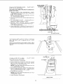
1. Using
a small
size
screwdriver,
reach
UNDERNEATH
saw and loosen BOTH setscrews
in 90 ° STOP COLLAR.
NOTE: If you can't reach the setscrews,
turn the
TILT HANDWHEEL
slightly,
2. ROTATE the STOP
pivot nut.
COLLAR
mowng
it away from
3. TILT blade RIGHT or LEFT . . . checking
square until blade is square to table.
4. ROTATE
STOP
COLLAR
PIVOT NUT until it TOUCHES
TIGHTEN
the setscrews.
with your
/
moving
it toward
the PIVOT NUT..
\
I
SETSCREWS
(2)
5. Check POINTER.
if it DOES NOTpointtothe"O
mark on the bevel scale, bend pointer to read "O.
PIVOT
NUT
\
\
90 ° STOP
TILT blade to LEFT as far as it will go
when the PIVOT NUT is against
the
COLLAR.
COLLAR
It will stop
45 ° STOP
Place an ACCURATE
square against
blade. Make
sure square is not touching
the TIP of one of the saw
TEETH.
/
/
STOP
If blade
COLLAR
is NOT 45 ° to table
must be ADJUSTED
1. Remove
Elevation
. . . the
45 ° STOP
2. Using a small size screwdriver,
reach thru
slot
in front
trip
panel
and loosen
setscrews
in 45 ° STOP COLLAR.
reach the setscrews,
slightly.
COLLAR
\
TiLT SCREW
Handwheel,
NOTE: If you can't
TILT HANDWHEEL
45°
curved
BOTH
turn the
3. ROTATE the STOP COLLAR moving it IN or OUT
and TILT blade RIGHT or LEFT...checking
with
your square until blade is 45 ° to table.
4. TIGHTEN
the setscrews.
NOTE: If you can't reach the setscrews,
HANDWHEEL
slightly
5. Install
Elevation
turn TILT
l
Handwheet.
BACK
I!
OF SAW
BLADE
ELEVATION
When the elevation handwheel is turned CLOCKWISE, until it stops, the blade must not be more than
two and five eigths (2-5/8) inches above the table. If
the blade extends more than 2-5/8 inches, the motor
could interfere with the underside of the table
causing misalignment.
With the blade extending two and five eigths (2-5/8)
inches above the table, the STOP COLLAR and
SPACER must be against the ELEVATION SCREW
PIVOT NUT. If the blade extends more than 2-5/8
inches, loosen two screws in STOP COLLAR, and
readjust it.
ELEVATION
SCREW
/
f
!
/
ELEVATION
PIVOT
SCREW
NUT
1
\
COLLAF_
STOP
\,
TILT
SCREW
TILT
SCREW
PIVOT NUT
TILT AND ELEVATION
MECHANISM
The HANDWHEELS
should turn freely without
binding, The turning action can be adjusted by
tiqhtening or loosening the screws in the bearing
retainer. Both handwheels must be removed to
reach the adjusting screws.
ELEVATION
HANDWHEEL
TILT
HANDWHEEI
1
1
_
NOTE: When adjusting the screws on the TILT
bearing retainer, hold the nut inside using a 3/8 in.
wrench. The screws for the ELEVATION bearina
retainer can be reached with a small screwdrive_r
through the curved slot on the front of the saw.
ADJUST
THESE
TWO
SCREWS
ADJUST
THESE
TWO SCREWS
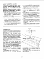
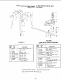
ATTACHING
AND ASSEMBLING
TABLE
EXTENSIONS
.TABLE
From among the loose parts find the followin
hardware: (Quantity indicated is for 2 extef
MOUNT TO TABLE
EXTENSION
USING
Ref.
No,
Description
1 Corner Support Bracket ............
2 Corner Stiffener Bracket ............
3 Truss Hd. Screw, 1/4-20 x 1 ........
4 External Lockwasher, 1/4 ...........
5 Hex Nut, 1/4-20 ....................
6 Flat Washer (Dia. of Hole 17/64) ....
HARDWARE FOR INSTALLING
EXTENSIONS TO SAW TABLE
7 Hex Hd. Screw, 5/16-18 x 1-1/4 .....
8 External Lockwasher, 5/16 ..........
9 Hex Nut. 5/16-18 ...................
10 Flat Washer (Dia. of Hole 11/32) ....
Assemble brackets with hardware as shown.
EXTENSION
Qty.
4
4
16
16
16
4
\\
OPPOSITE
3
/_f
6
6
6
6
__ UNDERSIDE
ASSEMBLED
12
VIEW OF
TABLE EXTENSION
)N
SIDE.
.,? ,2
Insertthree (3) 5/16-18x 1-1/4 in. long screws
through holes in each EXTENSION then through
table, tnstall flat washer, Iockwashers,
the screws...
DO NOT TIGHTEN.
and nuts on
Align front edge of extension with front edge of saw
table. Pull Extension
UPWARDS above table
surface . . . SLIGHTLY TIGHTEN SCREWS using
1/2 in. wrench.
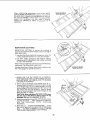
BLOCK
OF WOOD
Using small block of hardwood and hammer, tap
extension DOWNWARDS at front, center and rear,
until it is EVEN with table surface . . . TIGHTEN
SCREWS.
ALiGNiNG
CHECK
REAR
EXTENSIONS
AT FRONT
AND
OF EXTENSION
Lay REAR FENCE GUIDE BAR on table to act as a
straightedge.
If outer edge of extension
is higher or
lower than table surface:
1, Slightly
bracket
loosen nut
to extension
holding
the corner
support
using 7/16 in. wrench.
2. Move end of extension
edge is even with table
GUIDE BAR ... tighten
up or down until outer
surface . . . check with
nuts.
3. Recheck INNERedge
of extension
to make sure it
has not moved
.. readjust,
if necessary.
4. Adjust
right
extension
in same
manner.
/
FLAT
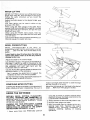
INSTALLING
AND SWITCH
RDP FENCE
GUIDE
WASHER
_'_C_
BARS
1. Locate the following loose parts:
Hex head screws 5/16-18 x 3/4 ............
External Iockwashers. 5/16 .................
Hex Nuts 5/16-18 .........................
Hex head screws, 5/16-18 x 1-1/2 ...........
Hex head screws 5/16-18 x 1 ..............
External Lockwashers
5/16 ................
Spacers, 3/4 x 1/2 .........................
Self threading nuts ........................
Washers, 21/64
...........................
Switch Assembly
..........................
LOCKWASHER
SPACER
2
2
4
2
2
4
2
2
4
1
_
_/1-3/4"'
FRONT
",-.-,___',_
6TH
1
HOLE
r_
2. Insert a 1-1/2 inch long screw, external lockwasher, and flat washer through the sixth hole in
the front fence bar.
3. Place 1/2 inch long spacer over screw th reads and
position screw through first hole on the right side
of the cast iron table skirt.
4. Use fingers to thread screw into tapped hole until
finger tight. Guide bar should be in a vertical
position.
13
SCREW
FENCE
eAR
L.; J
1-t/2"
HEX
LOCKWASHER
HD. SCREW
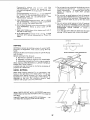
5. Mount switch to guide bar with 2 hex head screws,
5/16-18 x 3/4 Iockwashers,
and nuts, Securely
tighten both nuts.
FLAT
WASHER
LOCKWASHER
6. insert 1-1/2 inch long screw through
externa!
Iockwashers,
fiat washer and through the second
ho_e in the guide bar. Place t/2 inch long spacer
over screw thread& Swing g uide bar to horizontal
position
and screw the hex head screw into the
center hole of the table skirt. Finger tighten both
guide bar mounting
screws.
3/4"
HE× HD.
SCREW .......
LOCKWASHER
1
HEX HD.
SCREW
WASHER
\
\
LOCKWASHER
SELF.THREADING
7. Insert one inch Ion.q. screws
in first and third
t_oles of the rear guide bar and attach to tame
the same wav as the front bar
8 inset[ ends
of FENCE
GUIDE
BAR
ROO
through
holes _n bars as illustrated
NOTE: The ends of the RODare not threaded
o
the SELF THREADING
NUTS wdl cut threads
on the rod as they are screwed on. Just start nuts
onto ends of rod,
BAR aOO
Using TWO !/2 in. wrenches
both of the nuts.
--_/'
REMOVE
3 SCREWS
FROM
REAR
OF TABLE
EXTENSION
BEFORE
0NSTALLING
GUIDE
9. Hold rod with one hand and with a 1/2 in, wrench
or phers start screwing on ONE of the nuts only
A TURN OR TWO
screw on other nut the
same way
t0.
NUT
or pl_ers tighten
14
NUT
{
_,__
'%"
'_d"
X_-_r
._;;_
1t. Stidethe
bars so that screws
,of the _o_ted
" _ - holes
t2. Positio_
hoiding
end with
NOTE:
knob to
are
,J
"--::: i[
r_theMIDD_E
r_p fence over miler gauge groove
up the _ear end while engaging
front
bar
, • _ower fer_ce on_o tab!e
It may be necessary
to toosen fence
at_ow _ence to be ir_staIled on rip raft
8 THICKNESSES
OF PAPER
13, Move
FRON"f
ba_ upwards
approxmate!y
1,32 i_. above
screw at left end of bar.
unfi!
fer_ce is
tab!e . , tighten
NOTE: Fold a piece of newsp_:_per making
8
thicknesses
and p_ace betwee_
rip fence and
tab{e to act as a spacer. This wiit hold the fence
off of the table approx.
IJ32 in.
!4.
Adjust
rear
bar
so that
approximately
1/32 ir_, above
sc_ew at end of bar.
the
tabte
fence
is
. . . tighten
15, Replace screws in rear of table extension
__. be
sure top surface of exter_sion is PARALLEL
to
top surface of rea_ guide bar
\
8 THICKNESSES
OF PAPER
16, Move fence to RIGHT edge of _ab_e . ,, make
sure it is approximately
t/32 ino above table at
front and rear and tighten screws.
!
_5
ALiGNiNG
RiP FENCE
\
The fence should slide easily along the bars and
always remain in alignment (parallel to sawblade
and miter gauge grooves).
The alignment is maintained by a spring underneath
the rip fence which bears against the front guide
bar.
To move the fence, loosen the lock handle and
grasp the fence with one hand at the front.
\
For very close adjustments, grasp the guide bar with
both hands and move the fence with your thumbs.
Place fence on saw but DO NOT LOCK IT.
Move the REAR END of the fence slightly to the right
or left . . . when you release it, the fence should
"spring" back to its original position.
If it does not, the spring pressure must be
INCREASED.
_--_
1.Loosenthe screws.
2.MoveSpringslightlytowardfront of fence.
NOTE:Applyinga coatof pastewaxto therailswill
allowfenceto be movedmoreeasily.
If the fencedoesnotslideeasilyalongthebars,the
pressureof the springcanbe REDUCED.
1. Loosenthe screws.
2.Movespring slightly towardrear of fence . . .
SPRING
SCREWS
tighten screws.
SLIDE SPR_NG
TO
ADJUST
PRESSURE
The r_p fence must be PARALLEL
with the sawblade
and miter gauge grooves..
Move fence until it is
along side of groove. Do NOT LOCK IT. It should be
parallel
to groove.
If it is not:
1. Loosen
the two
"Hex
FENCE
HEA_
Head Screws.
2. Hold fence head tightly against bar..,
move end
of fence so that it is parallel with groove.
3. Alternately
tighten
the screws.
\
ADJUSTING
RiP SCALE
INDICATOR
1. Turn ELEVATION
HANDWHEEL
clockwise until
blade is up as high as (t will go.
IMPORTANT:
BLADE must be SQUARE (90 °) to
TABLE, in order to ALIGN rip fence.
2. Using a rule, position
fence
sawblade
2 in. from the sides
tighten lock handle.
3. Loosen screw
that it points
screw.
NOTE: If you
points to "2",
guide bar and
\
LOCK
on right side of
of the teeth . . .
holding the indicator..,
to "2" on the r{p scale..,
adjust so
tighten
cannot adjust indicator
loosen the screws holding
move the guide bar.
so that it
the front
\
\
_7
HANDi
SQUARE
iNSTALLiNG
1. From
among
as sh own.
BLADE
GUARD
the
parts
loose
find
NUT
K_FSPREADER
_
__.r--
TRUSS HEAD--.._
SCREW
the
_
"-" ---'
__._._"'__ /
SOCKET HEAD
SETSCREW
_
hardware
7/8 IN, LONG
FLAT WASHER
SUPPORT
SPREADER
I_l
_.
_
17/64 iN. HOLE
_
HEX NUT---_
SPREADER
If
_J_
o_
_,,_
_J_
BRACKET
J WING NUT 1/4-20
/
_
/
CLAMP
/
(_
_
LOCKWASHER
EXT. 1/4 IN,
\
2. Position
SPREADER
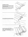
SUPPORTon
even with the end of the rod.
rod until
BLADE
WITH TABLE
it is
\
_RE
NUT
SPREADER
BRACKET
_
--
soc
HEAD
SETSCREW-_
FLAT R _
WASHE
LOCKWASHER
HEX NUT_
18
_
(_
5. Laya pieceofflatstraightwoodandasquareon
sawtableandrotatetheSPREADER
SUPPORT
unti the bracketis alignedwithsquare.
6. MAKESUREENDOF SUPPORT,BRACKET
AND RODARE EVEN. . . using an 1/8 in.
setscrewwrench,TIGHTENTHESETSCREWS
ONLY.
ENDS OF SUPPORT
AND BRACKET
TO
BE EVEN WITH
END OF ROD
/
TIGHTEN
SETSCREW
ONLY
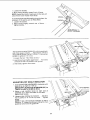
SPACE EQUAL TO APPROX.
3 THICKNESSES
OF PAPER KERF
the
cuthe
Sthe
re
r ust
der C|,
PARALLEL
NOTE:
to the sawblade
The spreader
KERF by approxirnately
is thinner
and in the MIDDLE
than the width
six thic knesses
of
.
OD
,
ADE
of the
of paper.
SPREADE/_/'_[
. .
SPACE'EQUAL
3 THICKNESSES
_'ii
i
TO APPROX.
OF PAPER
LOOKING DOWN ON SAW
7. Make two folds
in a small piece (6 x 6 in.) of
ordinary
NEWSPAPER
making
three
thicknesses.
The folded paper will be used as a
"spacing
gauge".
/
ANTIKICKBACK
PAWLS
8. Raise blade to max mum height and make sure
blade is square to the saw table.
9. Install the SPREADER
CLAMP.
Place spreader
between
spreader
clamp
and bracket,
Move
forward
until all three are in line, TIGHTEN
WINGSCREWS,
10. Lift up both ANTIKICKBACK
PAWLS ... insert
one of the setscrew
wrenches
or a pencil in the
notches to hold the pawls out of the way.
I
J
/
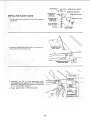
HOLD
PIECE
STRAIGHT
WOOD
OF
WOOD
!
TIGHTLY
AGAINST
BLADE
THREE
THICKNESSES
OF PAPER
11. Lay a piece of straight
flat wood against
the
sawblade.
Insert folded paper between spreader
and strip of wood.
12. MAKE SURE
ARE LOOSE.
THE HEX
NUTS
UNDERNEATH
13. Hold the spreader
tightly against the wood and
make sure the wood is against the saw blade.
TIGHTEN
THE HEX NUTS.
This will align the spreader
in the middle of the
cut (KERF) made by sawblade.
HOLD SPREADER
TIGHTLY AGAINST WOOD
NUT.J
SPREADER
CLAMP
SPREADER
BRACKET
.=---LOCK
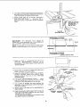
ADJUSTING FORMITER
WARNING:
YOUR
SWITCH
POWER
MITER
"OFF"
SOURCE
GAUGE
OWN
SAFETY,
AND
REMOVE
OUTLET BEFORE
PLUG
MAKING
"_._,
__
TURN
_._
(_, ._..
with
the bar
KNOB
_INTER
PG
SQUARE__
FROM
ANY
GAUGE
NOTE: The graduations
on the miter gauge provide
accuracy
for average woodworking.
In some cases
ADJUSTMENTS,
where extreme
accuracy
is required
when making
angle cuts, for example,
make a trial cut and then
recheck it with an accurate square or protractor.
If necessary, the miter gauge head can be swiveled
slightly to compensate for any inaccuracy.
2. Position
the lock
The HEAD should be SQUARE
when the pointer points to "O".
3. Loosen the screw
points to zero.
(90 ° ) with the bar
To check for squareness, place an accurate square
on the miter gauge. If the head is NOT SQUARE with
the bar:
1. Loosen
the
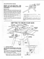
GETTmNG TO KNOW
GAUGE
KNOB
\
6 BLADE
GUARD
SAW
square
and
adjust
RIP
/
4
FENCE
/
INSERT
9 E_
HANDWHEEL
\
2
RIP FENCE
LOCK KNOB
HANDWHEEL
/
]
ON-OFF
SWITCH
/
/
1
ON-OFF
pointer,
YOUR SAW
ANTIKICKBACK
8
PAWLS
RLAD
SPREADER
5 MITER GAUGE
3 TILT
the
. tighten
so it
The swiveling
movement
of the head
can
be
adjusted
by tightening
or loosening
the set screw
located in side of the head using the 1/8 in. setscrew
wrench.
ock knob
MITER
LOCK
the head
knob.
SWITCH
CAUTION:
Before turning switch on, make sure the
blade guard is correctly
installed
and operating
properly.
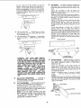
The On-Off
Switch
has a locking
feature.
THIS
FEATURE
IS
INTENDED
TO
PREVENT
UNAUTHORIZED
AND POSSIBLE
HAZARDOUS
USE BY CHILDREN
AND OTHERS.
@
A. TO turn saw ON...
stand to either side ofthe
blade never in line with it...
insert finger
under switch lever and pull END of lever out.
KEY
(YELLOW PLASTIC)
2O
HOLES
FOR
ATTACHING
FACING
4
Do not cycle the motor switch
on and off
rapidly,
as this may cause the sawblade
to
loosen. In the event this should
ever occur,
allow the sawblade
to come to a complete
stop and retighten thearbor
nut normally,
not
excessively.
Never leave the saw while the
power is "ON,.
©
©
B. TO turn saw OFF...
PUSH
leave the saw until the cutting
to a complete
stop.
If you are making
a rip type cut in material
thinner
than
3/16
in. while
the fence
is
positioned
over the depressed
area of table
extension,
the facing should be attached to the
fence so that the bottom edge touches the top
surface
of the extension.
In this case, the
facing must be shorter than the fence. This will
prevent thin material from sliding under the rip
fence.
lever in. Never
to01 has come
C. TO lock switch in OFF position..,
hold switch
IN with one hand..
REMOVE key with other
hand.
°
RiP FENCE ... is locked in place by tightening
the lock knob. To move the fence, loosen the
knob and grasp the fence with one hand at the
front.
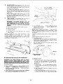
Holes
are
provided
in the rip fence
for
attaching
a wood facing when using the dado
head, or molding
head.
Select a piece of smooth straight wood approx.
3/4" thick, at least as long as the rip fence, and
at least 7-1/2" wide (high) to permit clamping
of featherboards.
Attach it to the fence with three Round Head
#10 Wood Screws 2 in. long. To remove the
facing,
loosen
the screws,
slide the facing
forward and pull the screws through the round
holes.
WOOD
FACING
t
°1
__
o
----_:
/
"--
WARNING:
FOR
YOUR
OWN
SAFETY,
LOWER
BLADE
OR
OTHER
CUTTING
TOOL BELOW TABLE SURFACE.
(IF BLADE
IS TILTED, RETURN
IT TO VERTICAL
(90 °)
POSiTiON).
ALWAYS LOCK THE SWITCH
"OFF".
WHEN SAW IS NOT IN USE . . .
REMOVE
KEY AND KEEP IT iN A SAFE
PLACE . • • ALSO . . . IN THE EVENT OF A
POWER FAILURE
(ALL OF YOUR LIGHTS
GO OUT) TURN SWITCH
OFF ... LOCK IT
AND
REMOVE
THE
KEY.
THIS
WILL
PREVENT
THE SAW FROM STARTING
UP
AGAIN WHEN THE POWER COMES
BACK
ON.
2
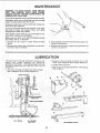
ELEVATION
HANDWHEEL
. • . elevates
lowers the blade. Turn clockwise
to elevate
counterclockwise
to lower.
3
TILT HANDWHEEL...
tilts the blade for bevel
cutting.
Turn clockwise
to tilt toward left
counterclockwise
to tilt toward vertical.
5
or
.
When the blade is tilted to the LEFT as far as it
will go, it should be at 45 ° to the table and the
bevel indicator
should point 45 ° .
NOTE: There are LIMIT STOPS on the saw
which prevent
the blade from tilting
beyond
45 ° to the LEFT and 90 ° to the RIGHT, (See
"Adjustments"
section
"Blade
Tilt,
or
Squareness
of Blade to Table").
21
ROUND
10 WOOD
HEAD
/
SCREWS
MITER GAUGE...
head is locked in position
for crosscutting
or mitering
by tightening
the
lock knob.
ALWAYS
LOCK
IT SECURELY
WHEN IN USE.
Slots are provided
in the miter
gauge for
attaching
an AUXILIARY
FACING
to make it
easier to cut long pieces.
Be positive
facing
does not interfere with the proper operation
of
the sawblade
guard.
Select
a suitable
piece of smooth
straight
wood . . . drill two holes and attach
it with
screws.
NOTE: When bevel crosscutting,
attach facing
so that it extends to the right of the miter gauge
and use the miter gauge in the groove to the
right of the blade.
6
BLADEGUARD
must always be m p_ace ann
working properly
for all thru-sawing
cuts That
ts all cuts whereby the blade cuts compieteiy
through
the workpiece
To remove the guard for special
operations
loosen the wing nuts and slide the guard off of
the rod DO NOT DISTURB
THE SETTING
OF
THE ROD
When replacing
the guard, make sure the PIN
in the rod engages
with the NOTCH
m the
spreader
support
Make sure wing screws are
tightened
securely
7
TABLE iNSERT is removable
for
installing blades or other cutting
removing
toots
or
WARNING:
TO AVOID
iNJURY
DUE
TO
ACCIDENTAL
START, TURN SWITCH
"OFF"
AND
REMOVE
PLUG
FROM
POWER
SOURCE
OUTLET
BEFORE
REMOVING
INSERT.
A
Lower
the blade
below
B
C
Raise blade guard
Loosen Screw
D
Lift insert from
fronl of saw
front
the table
end
and
surface
D To TIGHTEN
nut
against
rear of table
wrench toward rear
putl
NOTE: When installing
the blade
make sure the
teeth are pointing
toward the front of the saw
and
that the bnade and collars are clean, and free from
any burrs
toward
NEVER
OPERATE
THE
SAW
WITHOUT
THE
PROPER
INSERT
N PLACE
USE
THE
SAW
BLADE
INSERT
WHEN SAWING
USE THE
COMBINATION
DADO MOLDING
INSERT
WHEN
DADOING
OR MOLDING
The HOLLOW
blade
Always
HOLD ARBOR
wrench
PUSH ARBOR
NUT
side of the collars
tighten
E To repJace
Place insert
toward rear
over screw
the arbor
must be against
the
nut securely
insert
into insert opening
in table and push
of saw until keysmot in insert wilt drop
Tighten screw
Do not tighte_q screw
deflect the insert
to the point
where
it will
/
FLAT
SURFACES
COLLAR
_J
Q
/
SCREW
HEX NUT
TEETH
POINTING
TO
FRONT
OF SAW
8 REMOVING
AND INSTALLING
SAWBLADE
9
WARNING: TO AVOID iNJURY DUE TO ACCiDENTAL START, TURN SWITCH
"OFF"
AND
REMOVE PLUG FROM POWER SOURCE OUTLET
BEFORE REMOVING OR INSTALLING SAWBLADE.
A Remove insert.
EXACT-I-CUT
The 'yellow"
plastic disc imbedded in the table
in front
of the sawblade,
is provided
for
marking
the location
of the 'sawcut"
on the
workpiece
A Check disc
if it is above table surface
place a piece of hardwood
on top of it and tap
it down
B. Place ARBOR, wrench on flat surfaces of saw
ARBOR . .. ARBOR NUT wrench on nut _ ..
position wrenches as shown..,
hold your hands
welJ above blade
B With blade 90 ° (square
piece of wood
C With ARBOR wrench against table, PULL ARBOR
NUT wrench FOREWARD to LOOSEN nut
[o table)
cut
off a
C Pull miter gauge back until wood isoverdisc
Using very sharp pencil, mark a line on disc
22
D. With miter gauge
same procedure
disc.
in right hand qroove, tottow
aria mark an_other line on
E. These lines indicate the "path"
(kerf) made by the sawbiade.
SHOWN
WITH
(OPTIONAL
HOLD-DOWN
ACCESSORY}
F. When cutting the WOrkpiece,
workpiece
with line on disc.
line up mark
on
Use the hold-down
clamp (optional accessory)
on the miter gauge for greater accuracy.
of the cut
CLAMp
\
..............
-r111:_.
.............................. __
/
Y
h
..... _;.:h;:F
F
BLADE
GUARD
NOT
SHOWN
FOR
PICTURE
CLARITY
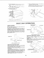
BASIC SAW OPERATION
THESE
WORK HELPERS
BE
Before cutting any wood on your saw study all of
the "Basic Saw Operations".
Notice that in order to make some of the cuts, it is
necessary
to use certain
devices
"Work Helpers"
like the Push Stick, the Push Block and the Auxiliary
Fence/Work
Support, which you can make yourself.
After you have made a few practice cuts
make up
these "helpers"
before starting
any projects
Make
the "Push Stick" first.
EDGES
MUST
PARALLEL
PUSH BLOCK
3/4
PLYWOOD
12
3/8
"i_'-
2-1/2 -,
2-112
................
3/8
3/4
"'_
- 3/8
._r"
NOTE:
AUXILIARY
PUSH STICK
Make
one
plywood.
Woodscrews.
NOTCH
All
dimensions
FENCE/WORK
in inches
3/8
using
a piece of
Fasten
together
318 in
with
and 314 m.
glue
and
NOTE:
Since the Push Block
is used
Auxiliary
Fence, the 4-3/4 in. dimensions
heqd identical
on both the pieces,
PUSH STICK
AND PUSH
PLYWOOC
SUPPORT
with the
must be
BLOCK
Makethe
Push Stick using a piece of I x 2, or rip one
from a wide board, say 1 !-1/2 in. wide, and set the
rip fence 9-7/8 in, from the sawblade.
Make the Push Block using aptece of 3/8 in and 3/4
in. plywood.
The small piece of wood 3/8 in. x 3/8 in. x 2-1/2 in.
should be GLUED to the plywood
... DQ NOT USE
NAILS, This is to prevent dulling the sawblade in the
event you mistakingly
cut into ihe push block.
Position the handle in the center of the plywoodand
fasten together
with glue and woodscrews.
THIS FACE AND THIS
EDGE MUST BE PARALLEL
3/8
PLYWOOD
_
_"
NOTE:
23
All dimension
in inches
5-1/2
_
/
USING
THE
MITER
GAUGE
6. Do not stand directly in front of the blade in case
of a THROWBACK
(Small cut-off piece caught
by the back of the blade and thrown toward the
operator).
Stand to either side of the blade.
THE
MITER
GAUGE
iS
USED
WHEN
CROSSCUTTING,
MITER
CUTTING,
BEVEL
CUTTING,
COMPOUND
MITER
CUTTmNG,
DADOING
and
when
RABBETTING
AND
MOLDING
across the end of a narrow workpiece.
7. Keep your hands clear of the blade and out of
the path of the blade.
8 ff blade stalls or stops
while cutting.
TURN
SWITCH
OFF before
attempting
to free the
blade.
WARNING:
FOR YOUR OWN SAFETY,
ALWAYS
OBSERVE
THE
FOLLOWING
SAFETY
PRECAUTIONS
iN ADDITION
TO THE SAFETY
iNSTRUCTIONS
ON PAGES 2, 3, and 4.
1. Never make these cuts freehand
(without
using
the miter
gauge
or other auxiliary
devices)
because
the blade could bind in the cut and
cause a KICKBACK
or cause your fingers
or
hand to slip into the blade.
2. Always
lock
the miter
gauge
securely
when
9. Do not reach over or behind the blade to pull the
work piece through
the cut..
to sup port long or
heavy workpieces..,
to remove cut-off pieces of
material or FOR ANY OTHER
REASON.
10. Do not pick up small pieces of cut-off material
from the table. REMOVE them by pushing them
OFF the table with a long stick. Otherwise
they
could be thrown back at you by the rear of the
blade.
in
use.
3. Remove
rip fence
from
table.
4. Make sure blade guard is installed for all "thrusawing"
operations
(when
sawblade
cuts
entirely
thru the thickness
of the workpiece.)
Replace guard IMMEDIATELY
after completion
of dadoing,
molding or rabbeting
cuts.
11. Do not remove small pieces of cut-off material
that may become
TRAPPED
inside the blade
guard while the saw is RUNNING,
THIS COULD
ENDANGER
YOUR
HANDS
or cause
a
KICKBACK.
5. Have blade extend apF)roximately
1/8 in above
top of workpiece.
Additional
blade exposure
would increase the hazard potential
Turn the saw OFF. After the blade
turning,
lift the guard and remove
has stopped
the piece.
WORKPIECE
CROSSCUTTING
CROSSCUTTING
is known as cutting wood across
the grain at 90 ° , or square with both the edge and
the flat side of the wood. This is done with miter
gauge set at "0".
T
TABLE
The graduations
on the miter
gauge
provide
accuracy
for average woodworking.
In some cases
where extreme
accuracy
is required,
when making
angle cuts, for example,
make a trial cut and then
recheck it with an accurate
square, or protractor.
If necessary,
the miter
slightly
to compensate
I
\
gauge head can be swiveled
for any inaccuracy.
NOTE: The space between the miter gauge
the groove in the table is held to a minimum
manufacturing.
1'
SANDPAPER
bar and
during
For max mum
accuracy
when
using
the miter
gauge, always 'favor
one side of the groove in the
"
table. In other words, don t move the miter
gaug e
from side to side whiWe cutting,
but keep one side of
the bar riding aga nst one side of the groove.
NOTE: Glue a piece of sandpaper
to the face of the
miter
gauge
head.
This will
help prevent
the
workpiece
from "creeping"
while it is being cut.
The
Hold-Down
Clamp
(Optional
Accessory)
should
be used on the miter gauge for greater
accuracy.
The miter gauge
may be used in either of the
grooves in the table. Make sure it is locked.
When using the miter gauge
in the LEFT
hand
groove, hold the workpiece
firmly against the miter
gauge head with your left hand, and grip the lock
handle with your right.
When using the RIGHT
Hand groove,
hold the
workpiece
with your right hand and the Iockhandle
with your left hand.
-
24
\
AUXmLIARY FENCE/
WORK SUPPORT
When cutting
long workpieces,
invert AUXtLaARY
FENCE/WORK
SUPPORT and position
it on top of
the guide bars to support the workpieces
as near to
the end as possible.
If this does not adequateVy
support
the workpiece,
you can make a sirnp_e
support
by clamping
a piece of plywood
to a
sawhorse.
REPETiTiVE
CUTTmNG
REPETITIVE
CUTTING
is known
as
quantity of pieces the same length without
mark each piece.
cutting
having
a
to
1. Use the Stop Rods (optional
accessory)
only for
cutting
duplicate
pieces 6 in long and longer.
2. DO NOT FEED workpiece
with RIGHT
Hand,
merely guide it. making sure that it does not bind
or pinch the sawblade.
When making repetitive cuts from a long workpiece,
make sure it is adequately
supported,
Use the Hold-Down
Clamp (Optional
Accessory)
the miter gauge for greater accuracy.
AUXILIARY
FENCE/
WORK
SUPPORT
on
1. NEVER USE THE RiP FENCE
AS A LENGTH
STOP BECAUSE
THE CUTOFF
P_ECE COULD
BiND BETWEEN
THE FENCE AND THE BLADE
CAUSING
A KICKBACK
\\
\
\
\
2. When making
repetitive
cuts shorter
than 6 in.,
clamp a block of wood 2 in. long to the table to act
as a length stop, Do not clamp directly
to the
bottom edge of the table because the "swivel"
of
the clamp will not grip properly.
Place a small
block of wood between the bottom
edge of the
table and the "C" clamp,
CAUTION:
When clamping the block, make sure
that the end of the block is we!! in front of the
sawblade. Be sure it is clamped securely.
BLOCK
3. Slide the workpiece along the miter gauge until it
touches the block..,
hold it securely
or clamp
it
with
the
Hold-Down
Clamp
(Optional
Accessory).
4. Make the cut..,
pull the workpiece
back..push
the cut off piece off the table with a long Push
stick...
DO NOT ATTEMPT
TO PICK iT UP AS
THIS COULD ENDANGER
YOUR HANDS.
25
MITER
CUTTING
MITER
CUTTING
is known as
angle
other than 90 ° with the
Follow
the same
procedure
crosscutting.
Adjust
the miter gauge to the
io_k it.
cutting wood at an
edge of the wood.
as you would
for
desired
angle,
TOP
. _EW
and
The
miter gauge
may be used in either
of the
grooves
in the table,
When
using the miter
gauge in the LEFT Hand
groove,
hold the workpiece
firmly against the miter
gauge head with your left hand, and grip the lock
knob with your right.
When
using the RIGHT
hand groove,
hold
the
workpiece
with your right hand and the knob with
your left hand.
Use the Hold-Down
Clamp (Optional
Accessory)
on
the miter gauge for greater accuracy.
BEVEL
CROSSCUTTSNG
WORKPIECE
BEVEL
CROSSCUTTING
is the same
as
crosscutting
except that the wood is also cut at an
angle . . . other than 90 ° with the flat side of the
wood,
Lower blade to about 2 inches above the table top
before tilting blade. Failure to do this may result in
damage to your saw.
Adjust
the blade
to the desired
\
angle.
\
Use the M ter Gauge in the groove to the RIGHT
of
the blade. It cannot
be used in the groove
to the
LEFT because
the blade guard will interfere.
Hold
the
workpiece
with
your
right
hand
and
the
iockhandle
with your left hand.
Use the AUXILIARY
FENCE/WORK
SUPPORT
for
additional
support
of the workpiece.
Lay it accross
the guide
bars to support
workpiece
as near to the end as possible.
Use the Hold-Down
Clamp (Optional
Accessory)
the miter gauge for greater accuracy.
COMPOUND
COMPOUND
miter
cutting
USING
MITER
the
\
on
\
made at an angle other than
and the flat side of the wood
CUTTING
MITER CUTTING
is a combination
and bevel crosscutting.
The cut
THE
\
90 ° to both
the edge
Adjust the miter gauge and the blade to the desired
angle ... Make sure miter gauge is locked.
of
is
RiP FENCE
RIPPING,
BEVEL
RIPPING,
PLOUGHING,
MOLDING,
RESAWING AND RABBETING
are
performed using the RIP FENCE together with the
AUXILIARY
FENCE/WORK
SUPPORT,
PUSH
STICK OR PUSH BLOCK.
WARNING: FOR YOUR OWN SAFETY, ALWAYS
OBSERVE
THE
FOLLOWING
SAFETY
PRECAUTIONS
IN ADDITION
TO THE SAFETY
INSTRUCTIONS
ON PAGES 2, 3, and 4.
1. Never make these cuts FREEHAND
using the rip fence or auxiliary devices when
required) because the blade could bind in the
cut and cause a KICKBACK.
2. Always lock the rip fence securely when in use.
3. Remove miter gauge from table.
4. Make sure blade guard is installed for all thrusawing
type cuts.
Replace
the guard
IMMEDIATELY
following
completion
of
resawing, rabbeting,
dadoing, or molding
operations.
(without
26
Frequently check the action of
ANTIKICKBACK
PAWLS
by passing
workpiece
alongside
of the spreader
while
is OFF.
the
the
saw
Do not reach over or behind the blade to pull the
workpiece
through the cut.,,
to support long or
heavy workpieces
. . . to remove small cut-off
pieces
of
material
or
FOR
ANY
OTHER
REASON.
Pull the workpiece
TOWARD
you. If the PAWLS
do not DIG into the WOrkpiece
and HOLD
it...
the
pawls
must
be
SHARPENEDSee
"Maintenance"
section.
Do not pick up small pieces of cut-off material
from the table. REMOVE them by pushing them
OFF the table with a long stick. Otherwise
they
could be thrown back at you by the rear of the
blade.
5. Have blade extend approximately
1/8 in. above
top of workpiece.
Additional
blade
exposure
would increase the hazard potential.
11. Do not remove small pieces of cut-off material
that may become
TRAPPED
inside the blade
guard while the saw is RUNNING.
THIS COULD
ENDANGER
YOUR
HANDS
or cause
a
KICKBACK.
6. Do not stand directly
in front of the b_ad e i n case
of a KICKBACK.
Stand
to either side
of the
blade.
7. Keep your hands clear
the path of the blade.
of the blade
and
out
of
Turn the saw OFF. After the blade
turning,
lift the guard and remove
has stopped
the piece.
8. If the blade stalls or stops while cutting.
TURN
SWITCH
OFF before
attempting
to free
the
blade.
WORKPIECE
l ......
RIPPBNG
RIPPING
is known as cutting
a piece of wood
with
the grain, or lengthwise.
This is done using
the rip
fence.
Position the fence to the desired WIDTH OF R IP and
lock in place.
Before starting to rip, be sure
A. Rip Fence is parallel
to sawblade.
B. Spreader
is properly
aligned
with sawblade.
C. Antikickback
pawls are functioning
properly.
When ripping LONG BOARDS
or LARGE PANELS,
always use a work support.
A simple one can be made by clamping
a piece
of
plywood
to a sawhorse.
BEVEL
ALWAYS
RiPPiNG
When bevel ripping material
6 in. or narrower,
use
fence on the right side of the blade ONLY. This
will
provide
more space between
the fence
and
the
sawblade
for use of a push stick. If the fence
is
mounted
to the left, the sawblade
guard
may
interfere
with proper use of a push stick.
When "WIDTH OF RIP" is 6 in. and WIDER use
your
RIGHT Hand to feed the workpiece
until it is clear
of
the table.
Use LEFT hand ONLY to guide the workpiece...do
not FEED the workpiece
with the left hand.
27
SUPPORT
LOI_G
WORKPIECES
When
PUSH
' WIDTH O FR Ip" is 2in. to 6 in. wide USETH
STICK to feed the work.
E
When WIDTH OF RIP is NARROWER than 2 in., the
push stick CANNOT be used because the guard will
interfere . . . USE the AUXILIARY FENCE/WORK
SUPPORT and PUSH BLOCK.
Attach Aux tiary Fence/Work Support to rip fence
w " thtwo _C _ clamp S
Feed the workpiece by hand along the AUXILIARY
FENCE until the end is approx. 1 in. past the front
edge of the table. Continue to feed using the PUSH
BLOCK.
Hold the workpiece in position and install the PUSH
BLOCK by sliding it on top of the AUXILIARY
FENCE/WORK SUPPORT (Th s May Ra se Guard).
28
BAFFLE
Narrow strips thicker than the Auxiliary Fence/Work
Support may enter the guard and strike the baffle.
CAREFULLY raise guard only enough to clear the
workpiece. Use PUSH BLOCK to complete cut.
AUXILIARY
CUTTING
FENCE/
RT
PANELS
When cutting panels (whenever
fence is positioned
outside
of table
surface),
ALWAYS
use
the
AUXILIARY
FENCE/WORK
SUPPORT.
1. Unlock fence and raise rear end.
2. Position AUXILIARY FENCE/WORK SUPPORT
as shown and attach it with two "C" clamps.
PLOUGHING
AND MOLDING
PLOUGHING is grooving with the grain the long
way of the workpiece, using the fence. USE proper
holddowns and feed devices.
MOLDING is shaping the workp_ece with the grain
the long way of the workpiece, using the fence, Use
proper holddowns and feed devices.
PLOUGHING
MOLDING
29
RESAWING
RESAWING is a "thru-sawing"
cut made by ripping
a piece of wood through its thickness. Do not
attempt to resaw BOWED or WARPED material.
NOTE: To RESAW a piece of wood wider than 3-3/8
in.... it will be necessary to remove the blade guard
, . . and use the AUXILIARY
FENCE/WORK
SUPPORT. (See "Work Helpers").
Clamp it to the table so that the workplece will
SLIDE EASILY but not TiLT or MOVE SIDEWAYS
between the two fences.
Do not clamp d,,rectly !o the bottom edge of the table
because the swivel' of the clamp wil not grip
proper y Place a small block of wood between the
bottom edge of the table and the "C" clamp.
WARNING: FOR YOUR OWN SAFETY...
1. DO NOT "BACK UP" (REVERSE FEEDING}
WHILE RESAWING BECAUSE THIS COULD
CAUSE A KICKBACK.
2. MAKE FIRST PASS TO A DEPTH SLIGHTLY
LESS THAN ONE-HALF THE WIDTH OF THE
BOARD;
KEEP SAME FACE OF BOARD
AGAINST FENCE FOR SECOND PASS AS THE
FIRST PASS.
3. iNSTALL BLADE GUARD iMMEDiATELY UPON
COMPLETION
OF THE
RESAWmNG
OPERATION.
RABBETING
RABBETING is known as cutting out a section of the
corner of a piece of rnaterial, across an end or along
an edge.
FIRST
To make a RABBET requires cuts which do not go
all the way through the material, Therefore the blade
guard must be removed.
1. Remove
blade
guard,
Use caution,
Use
featherboards and push sticks etc, as required.
CUT
RABBET
2. For rabbeting along an edge (long way of
workpiece) as shown, add facing to rip fence
approximately
as high as the workpiece is wide.
Adjust
rip fence
and blade
to required
dimensions; then make first cut with board flat on
table as any rip (type) cut; makesecond cutwith
workpiece on edge. Follow all precautions, safety
instructions, and operational instructions as for
ripping, or rip type operations, including feather
boards and pusl_ stick, etc.
WARNING: FOR YOUR OWN SAFETY, iNSTALL
BLADE
GUARD
iMMEDiATELY
UPON
COMPLETION OF RABBETING OPERATION.
3. For rabbeting across an end, for workpiece 101/2" and narrower make the rabbet cut with the
board flat on thetable using the miter gauge fitted
with a facing. DO NOT use the rip fence.
Rabbet cuts can also be made using the dado head
or molding head
DADOING
instructions for operating
the Dado Head are
contained in booklet furnished with the Dado Head.
The Recommended
Dado Head is listed under
Recommended Accessories in this manua!.
® ®
The arbor on the saw, is only tong enough so that
the widest cut that can be made is 13/16" wide.
it is not necessary to install the outside loose collar
before screwing on the arbor nut. Make sure the
arbor nut is tight.
ALWAYS USE DADO INSERT LISTED UNDER
RECOMME NDED ACCESSORIES.
When using the dado head it will be necessary to
remove the Blade Guard and Spreader. USE
CAUTION.
USE FEATHERBOARDS
AND PUSH
STICKS AS REQUIRED.
WARNING: FOR YOUR OWN SAFETY, ALWAYS
REPLACE THE BLADE GUARD AND SPREADER
WHEN YOU ARE FINISHED DADOING.
3O
MOLDING
CUTTING
instructions
contained
Head.
for operating
the
in a booklet furnished
The recommended
molding
Recommended
Accessories
Always
use
Recommended
USING
Molding
Head are
with the Molding
head
in this
Molding
insert
Accessories.
is listed
manual.
Listed
When using the molding head it wilt be necessary
to
remove
the
Blade
Guard
and Spreader.
USE
CAUTION:
USE FEATHERBOARDS
AND
PUSH
STICKS, etc. AS REQUIRED.
under
WARNING:
FOR YOUR OWN SAFETY,
ALWAYS
REPLACE
THE BLADE GUARD
AND SPREADER
WHEN YOU ARE FINISHED
MOLDING.
Under
FEATHERBOARDS
Featherboards are not employed during non thrusawing operations when using the miter gauge.
has
been
(sawblade,
pushstick,
Use featherboards for all other non "_hru-sawing"
operations
(when sawblade
guard
must be
removed). Featherboards are used to keep the work
in contact with the fence and table as shown, and to
stop kickbacks.
Before
starting
the operation
cutter below table surface):
Add 8 inch high flat facing board to the fence, the
full length of the fence.
Mount featherboards to fence and table as shown,
so that leading edges of featherboards wil! support
workpiece until cut is complete, and the workpiece
"C"
pushed
completely
dado head, molding
as in ripping.
past
head,
(switch
the
etc.)
cutter
with a
"OFF"
and
(a)
Install featherboards
so they exert pressure on
the workpiece;
be positive they are secure, and
(b)
Make sure by trial that the featherboards
stop a kickback
if one should occur.
wit_
Replace the sawblade guard as soon as the non
thru-sawing operation is complete.
CLAMPS
iATHERBOARD
"C"
"C" CLAMPS
WORK
CLAMPS
SUPPORT
\
MOTOR
LUBRiCATiON
AND
MAINTENANCE
NOTE:
The
speed
of
regulated
or changed.
1, The bearings, in both end shields of the motor,
have been lubricated at the factory with correct
lubricant. No other part of the motor requires
lubrication.
4.
2. Re-lubricate
motor bearings
in accordance
with
the instructions
on the nameplate.
Be sure to
wipe off dirt or grit if present around oil hole caps
to prevent
any possibility
of foreign
material
contaminating
the oil wicks
that supply
the
bearings
with oil. Use a good grade of medium
weight mineral oil, such as automobile
engine oil
SAE 20.
this
motor
cannot
be
Every effort should
be made to prevent
foreign
material from entering
the motor. When operated
under conditions
likely to permit accumulations
of dust, dirt, or waste within the motor, a v_suaJ
inspection
should be made at frequent
intervals,
Accumulations
of dry dust can usually be blown
out successfully,
NOTE: Motors used on wood-working
tools are
particularly
susceptible
to the accumulation
of
sawdust and wood chips and should be blown out
or "vacuumed"
frequently
to prevent interference
with
normal
motor
ventilation
and
proper
operation
of the centrifugally-operated
starting
switch.
3. If disassembly
of the motor is necessary,
it should
be returned
to your nearest Sears retail or mailorder
store
n order
to prevent
voiding
the
guarantee.
31
MAINTENANCE
WARNING: TO AVOID iNJURY, TURN SWITCH
"OFF"
AND REMOVE
PLUG FROM POWER
SOURCE OUTLET BEFORE MAINTAINING
OR
LUBRiCATiNG YOUR SAW.
Do not allow sawdust to accumulate inside the saw.
\
Frequently blow out any dust. that may accumulate
inside the saw cabinet and the motor.
Frequently clean your cutting
Gum and Pitch Remover.
tools with Craftsman
A coat of automobile-type
wax applied to the table
will help to keep the surface clean and allow
workpieces to slide more freely.
If the power cord is worn or cut, or damaged in any
way, have it replaced immediately.
Make sure the teeth of the ANTIKICKBACK
are always sharp, To sharpen:
pawls
1. Identify the dull tooth or teeth. Remove blade
guard.
2. Rotate pawl toward rear of spreader so that teeth
are above top of spreader.
3. Hold spreader with left hand and place pawl over
corner of workbench.
4. Sharpen the dull tooth using a few light strokes of
a fine-cut round file.
LUBRiCATiON
The saw motor bearings have been packed at the
factory
with proper
lubrcant
and require no
additional lubrication. The following parts should
be oiled occasionally
with SAE No. 20 or No. 30
engine oil,
2. Elevation screw threads and pivot nut. (First
Clean with Craftsman Gum &Pitch Remover.)
3. Cradle bearing points.
4. Bearing points in guard assembly, miter gauge
and rip fence.
1. Tilt screw threads and pivot nut. (First Clean
with Craftsman Gum & Pitch Remover.)
STOP
COLLAR
SPACER
/
STOP COLLAR
\
\
TILT SCREW
TILT SCREW
PIVOT NUT
BEARING
32
POINTS
RECOMMENDED
UTEM
ACCESSORIES
CAT. NO.
iTEM
Steel Legs ............................
9-22235
Steel Stand
...........................
9-22214
Caster Sets .................
9-22222 or 9-22221
Solid Table Extension
.................
9-29954
*7 in. Molding
Head Set .......
9-3217 or 9-3218
*7 in. Molding
Head .....................
9-3214
MoldingiDado
Insert for 7 in.
Dia. Molding
or dado Head ............
9-29933
Work Light
.............................
9-2480
Work Light
.............................
9-2481
Sawdust Collector
......................
9-29967
NO.
7 in, Dia. Adjustable
Dado Head
. 9-3261, 9-3262
& 9-3263
7 in. Dia. Dado Head ....................
9-3257
Sanding Wheel
.........................
9-2274
Miter-Gauge
Stop Rods
...............
9-29924
Miter-Gauge
Hold-Down
Clamp
.......
9-29928
Taper Jig ...............................
9-3233
Universal
Jig
...........................
9-3231
"Power Tool Know How Handbook
Table Saw ............................
9-29!8
The above recommended
accessories
and were available
at the time this
printed.
"Smaller Dia. Molding Heads cannot be used
because they do not provide adequate depth of cut.
TROUBLE
CAT.
are current
manual
was
SHOOTING
WARNING: TO AVOmD INJURY, TURN SWITCH "OFF" AND ALWAYS REMOVE PLUG FROM POWER SOURCE
OUTLET BEFORE TROUBLESHOOTING.
SHOOTING
TROUBLE
TROUBLE
PROBABLE
-- GENERAL
CAUSE
REMEDY
Excessive vibration.
1. Blade
Cannot make square
Cut when crosscutting.
1. Miter gauge
Cut binds, burns or
stalls motor when
1. Dull blade with improper
ripping.
2. Blade is Heeling.
3. Warped board.
out of balance.
1. Discard
not adjusted
Blade
and use a different
1. See "Adjusting
Miter
blade.
Gauge."
properly.
tooth
1. Sharpen
or replace
blade.
set
2. See "Heeling
3. Make sure
"down,"
4. Rip fence
Adjustment.."
concave
feed
or hollow
side is facing
slowly.
not parallel
4. See "Aligning
Rip Fence"
out of
5. See "Aligning
Spreader.
to blade.
5. Spreader
alignment.
Cut not true at 90 °
or 45 ° positions.
Tilt and elevating
handwheei turn hard.
1. Stop screws
not properly
1. See "Blade
adjusted,
1. Sawdust
screw
on threads
or elevating
2. Bearing
Tilt".
or "Squareness
to Table."
of tilt
screw.
1. See "Maintenance
section.
2. See "Tilt
retainers
too tight.
33
and Lubrication"
Mechanism."
of Blade
TROUBLE
SHOOTmNG
NOTE: The starting
relay is a GRAVITY
SENSITIVE
TYPE. NEVER TURN THE POWER ON WHILE THE
SAW IS UPSIDE
DOWN AS THIS WILL DAMAGE
THE MOTOR.
NOTE: Motors used on wood-working
tools are
particularly
susceptible
to the accumulation
of
sawdust and wood chips and should be blown outor
"vacuumed'
frequently to prevent interference with
normal motor ventilation.
TROUBLE
-- MOTGR
PROBABLE CAUSE
r Excessive noise.
REMEDY
1. Motor.
1. Have motor checked
]
technician.
by qualified
service
Repair service is available at
your nearest Sears store.
Motor fails to develop
full power. NOTE:
LOW VOLTAGE:
1. Circuit overloaded with
lights, appliances
2. Increase wire sizes, or reduce length of
wiring. See "Motor Specification
and
too long.
For
of 10% in voltage
causes a reduction
]"9% in m aim
x um
Electrical
3. General overloading
,-
of
,
of which
the motor is capable,
and a reduction of 20%
in volta g e causes a
_
uL
or motors on
when using the saw.
other motors.
2. Undersize wires orcircuit
example, a reduction
power output
same circuit
I
•
(Power output of motor
decreases rapidly with
decrease in voltage at
motor terminals.
1. Do not use other appliances
and
reduction
of 36% in
maximum
output.)
power
of
power company
faci t es ( n some
sections of the country,
demand for electrical
power may exceed the
capacity of existing
generating and
distribution systems )
4. Incorrect
section.
,
fuses or circuit
comDa nv_.
4. Install correct
fuses or circuit
breakers.
breakers in power line.
,
i
Motor starts slowly
or falls to come up
to full speed.
Requirements"
3. Request a voltage check from the power
I
1. Low voltage wilt not
1. Request voltage check from the power
trip relay,
2. Windings burned out
company.
2. Have motor
or open.
3. Starting relay not
operat ng
34
repaired or replaced.
TROUBLE
TROUBLE
Motor overheats.
SHOOTING
-= MOTOR
PROBABLE CAUSE
REMEDY
1. Motor overloaded.
1.
normal air
circulation through motor.
See "Maintenance and Lul
through motor due to
sawdust.
operate.
Feed work slower into blaq
2. Clean out sawdust to prov
2. Improper cooling. (Air
circulation restricted
Starting switch in
motor will not
{Continued)
cation"
section.
I. Burned switch contacts
1. Have switch
(due to extended hold-in
check
replaced
from
the power
and r
con
_uest a voltage
pany.
periods caused by low
line voltage, etc.)
Motor stalls
(resulting in blown
fuses or tripped
circuit breakers).
2. Saw not in upright
position.
2. Place saw in upright positi )n.
3. Loose or broken
connectors.
3. Have wiring checked and repaired.
1. Starting
1. Have
relay
not
relay
replaced.
operating.
2. Voltage
motor
too low to permit
2, Request
to reach operating
voltage
check
fro
the power
company.
speed.
3. Fuses
or circuit
breakers
3. install proper
size fuses or circuit
breakers.
do not have sufficlent
capacity,
Frequent opening of
fuses or circuit
breakers.
1. Motor
overloaded.
2. Fuses or circuit
1. Feed work
breakers
2. Install
slower
proper
capacity.
operating
not
switch
(motor
not
3. Have relay
does
reach speed).
35
blade.
size fuses or circuit
do not have sufficient
3. Starting
into
replaced.
breakers.
m
PARTS
LIST FOR CRAFTSMAN
MODEL
10 INCH
NO.
DIRECT
DRIVE
SAW
113.226640
3
4
8
_"'--
5
[
I
5O
49
48
38
I
18
\
23
\
22
21
19
\
\
21
\
46
3O
29
51
Figure
54
1
PARTS
LIST FOR CRAFTSMAN
10 iNCH DIRECT
MODEL NO, 113,226640
Always
order
by Part
Number
FIGURE
Key
No.
Part
No.
62694
62782
447441
62514
62545
62805
62643
STD541625
STD551225
62642
62636
60314
60074
62644
STD551012
STD541025
STD523110
62541
60388
62770
STD551031
STD551231
STD54!231
71165
25 STD375006
26 62539
27 62710
28 62709
!
2
3
4
5
6
7
8
9
10
11
12
13
14
15
16
17
18
19
20
21
22
23
24
29
30
62936
62442
- not
1 PARTS
by Key
Gauge Assembly,
Miter (See Figure 5)
Fence Assembly,
Rip (See Figure 3)
Screw, Flat Hd. Type "T' 10-32 x 7/8
Insert Assembly
(Includes
Key No. 5)
Clip, Retaining
Guard Assembly
(See Figure 6)
Clamp, Spreader
*Nut. Wing 1/4-20
*Lockwasher.
External Tooth 1/4
Support,
Spreader
*Nut, Square 1/4-20
Screw, Truss 1/4-20 x 5/8
Part
No.
31
32
33
34
35
36
37
38
I
No.
i39
162924
160256
_62975
_67085
_STD511105
_STD600603
_62970
_STD601103
I STD551210
41 _62968
42 | STD541411
43 | $TD523115
44 |62204
STD551025
451
46
47
48
49
50
51
52
Nut, Self Threading
Rod, Separation
(Includes
Key No. 18)
*Washer.
21/64 x 5/8 x 1/16
*Lockwasher.
External Tooth 5/16
*Nut. Hex 5/16-18
Tie Wire
*Connector.
Wire
Spacer. Fence Guide Bar
Tape. Fence
Bar Assembly,
Fence Guide
(Includes
Key No. 27)
Lead Assembly
Switch, Locking
*Standard
Locally.
Number
40 I $TD523107
Screw, Set Hex Cup 1/4-20 x 7/8
Bracket
*Washer,
17/64 x 9/16 x 1/!6
*Nut. Hex 1/4-20
Screw. Hex Hd. 5/16-!8
x 1
Bar. Fence Rear
Hardware
| STD610805
|62689
|STD5II107
|62973
|62972
|3540
|37887
53 160096
54|63062
--|6z978
--|62980
I -/62981
I -|62982
I
/ 62983
I --/62984
I -- 1507421
L_62969
Item
SAW
LiST
Key_
Description
DRIVE
- May
be
Purchased
Description
Key, Switch
Relay
Cord with Plug
*Screw, Pan Cross 10-32 x 1/2
*Screw, Pan Cross Type "T" 6-32 x 3/8
Housing,
Switch
*Screw,
Pan Rec. Type "T" 10-32 x 3/8
*Lockwasher,
External
No. 10
Plate, Switch
*Screw,
Hex Hd. 5/16-18 x 3/4
Bracket,
Switch
*Locknut,
Hex 10-32
*Screw, Hex 5/16-18 x 1-1/2
Clip, Cord
*Washer,
17/64 x 47/64 x .062
*Screw, Pan Hd., Type "AB" No. 8 x 1/2
Handwheel
Assembly
*Screw, Pan Cross 10-32 x 3/4
Panel, Trim
Panel, Front
Wrench,
Arbor
Wrench,
Hex "L" t/8
Wrench,
Hex "L" 3/16
Wrench, Shaft
Bag of Loose Parts (Not Illustrated)
Bag of Loose Parts (Not Illustrated)
Bag of Loose Parts (Not Illustrated)
Bag of Loose Parts (Not Illustrated)
Bag of Loose Parts (Not Illustrated)
Bag of Loose Parts (Not Illustrated)
Bag of Loose Parts (Not Illustrated)
Owners
Manual (Not illustrated).
PARTS
LIST FOR CRAFTSMAN
!0 INCH DIRECT
MODEL NO. 113o226640
DRIVE
SAW
7
_J
9
42
J
8
12
/
13
14
/
!7
16
32
12
Figure
2
15
PARTS LIST FOR CRAFTSMAN
10 INCH DIRECT
MODEL NO. 113.226640
FIGURE
Key I
No. I
i
2
3
4
5
6
Part
No.
,62977
1805297-1
162493
162976
I STD55!010
ISTD511!10
! 62624
8 I STD55t2!0
9 I STD54t110
!01 62792
111 62962
121 62498
131 62683
141 60175
151 6362
161 60303
171 62681
18 I 60328
191 62647
201 62648
21 ! STD551037
Description
Tabie, Saw
Screw, Fiat Hd. 5/16-18 x I-1/4
insert, Exact-l=Cut
Support,
Rod
"Washer, 7/32 x 7/16 x !/16
"Screw, Pan Cross 10+32 x !
Rod+ Cradle
"Lockwasher_
External Tooth No, 10
"Nut, Hex No, !0-32
Spacer, Cradte Rod
oMotor
Collar, Blade
Collar, Stop L.H.
.++B+ade, Saw 10 inch
Nut+ Arbor
Spacer
Nut, Elevation
Pivot
Washer+ Nylon
Washer, Rubber
Washer, Rubber
*Washer+ .380 x 47/64 x 1/16
"Standard
Hardware
Item - May be Purchased
Locally.
eAny attempt
to repair" this motor may create a
HAZARD
unless repair is done by a qualified
service technician
Repair service is available
at
your nearest Sears Store,
2 PARTS
Key
No,
DRIVE SAW
LIST
Pa rt
NO.
22 60301
23 STD541411
24 62437
25 60436
26 60076
27 62796
28 62682
29 !STD511110
30 STD541425
31 STD551!3!
32 60078
STD51t!05
33
34 62967
35 62685
36 62684
37' STD600803
38 62686
39 62436
40 62625
41 62435
42 62623
43 436594
Description
*Ring, Retaining
3/8
"Nut, Lock 10+32
Retainer, Bearing
_rRing, Retaining
7/16
Washer, +505 x 1+.i/8 x !/t6
Rod, Motor (Includes
Key #25)
Screw Assembly,
Elevation
*Screw, Pan Rec+ 10-32 x 1
"Nut Lock 1/4-20
"Lockwasher,
5/16
Screw, Hex Hd 5/16+t8 x t/2
"Screw, Pan Hd. !0+32 x I/2
Base, Saw
Nut, Bevel Pivot
Screw Assembly,
Tilt
+_rew,
Type +T" Pan 8_32 x 3/8
Ind+cator, Beve+
NuL Twin
Hanger
Washer+ Thrust 3/8 x 5/8 x 1/16
Crad+e Assembly
Screw_ Pan Hd 10-32x
1-I/2
-+-Stock Item + May be secured
through
the
hardware
departments
of most
Sears
Retail
Stores or Catalog Order Houses.
*If tt_is part is removed, discard and replace with a
new retain+ng ring
PARTS
LiST
FOR
CRAFTSMAN
MODEL
NO.
10 raNCH DIRECT
113.226640
DRIVE
SAW
lO
,
FIGURE
Key
Part
No.
No.
3 =
STD551210
STD611005
__ 17j
*Standard
FENCE
ASSEMBLY
Description
62782
1 62693
2 62692
3 STD551031
4 62775
5 9404336
6 62774
7 423350
8 62526
9 STD600805
!0 62528
11 62529
12 62531
13 62530
14 62533
15
16
62782
Fence Assembly,
Rip
Plug, Button
Knob (includes Key No. 1)
*Washer, 21/64 x 1/2 x 1/32
Indicator, Fence
*Screw, Pan Hd. Type "T" 4-40 x 1/4
Head, Fence Includes
Key' #4
Screw, Sems 3/8-16 × 1/2
Channel,
Fence
Screw, Pan Hd. Type "T" 8-32 x 1/2
Spring, Fence Lock
Lock, Rear Fence
Roller, Rear Fence
Rod, Fence Lock
Spring, Head Alignment
(Includes
Key No. 17)
*Lockwasher,
External
Tooth No. 10
*Screw, Type "A" Hex Hd. No. 10 x 1/2
Pad: .Alignment
Hardware
Item
May be Purchased
40
Locally.
//
11
PARTS
4
LIST FOR CRAFTSMAN
MODEL NO.
10 iNCH DIRECT
113.226649
DRIVE
SAW
5
5
4
\\
/
\n
9
10
FIGURE
FIGURE
Key
No.
t
Part
No.
60314
2
3
62552
62554
4
5
6
7
8
STD551225
STD541025
62553
STD541250
803835
62767
4
62694 MITER
Description
Screw, Serrated
1/4-20 x 5/8
Truss
€Bag
Hardware
contains
Part
No.
1
2
3
4
5
62693
62692
STD551031
37893
STD600803
6
7
8
STD551208
62042
62252
9
10
11
12
62225
STD541231
62383
60288
Hd.
Leg
Stiffener,
Side
*Lockwasher,
Ext. 1/4
*Nut, Hex 1/4-20
Stiffener,
End
*Nut, Hex 1/2-13
Foot, Leveling
l-Bag of Loose Parts
(not illustrated)
"Standard
Key
No.
Items
all Loose
-Parts
41
May be Purchased
for
Legs.
GAUGE
5
ASSEMBLY
Description
Miter Gauge Assembly
Plug, Button
Knob (Includes
Key No. 1)
*Washer, 21/64 x 1 x 1/16
Gauge, Miter
*Screw, Pan Head Type "T"
8-32 x 5/16
*Lockwasher,
External No. 8
Indicator
Rod Asm., Miter Gauge
(Includes
Key No. 9, 10, 11)
Stud, Clamp
*Nut, Hex Jam 5/16-18
Stud, Pivot
Screw, Locking
1/4-20 x 3/8
Locally.
Set,
PARTS
1
LiST FOR CRAFTSMAN
10 iNCH DIRECT
MODEL NO. 113.226640
DRIVE
SAW
2__.
\
4
//
5
11
\\
8
_14
13
12
9
4_r
FIGURE
Key
NO.
6 m 62805
NO,
I
,
1
2 62516
6
7
8
GUARD
STD512515
62810
ASSEMBLY
Description
I
' Pin
*Screw, Pan Hd.; 1/4-20 x 1-1/2
Blade, Spreader
12
13
14 6029715 STD581025
*Standard
Hardware
Item -- May be Purchased Locally.
42
PARTS
LmST FOR
CRAFTSMAN
MODEL
NO.
10 iNCH DIRECT
113.226640
DRIVE
SAW
2
1
3
/
\
\
\
3
FIGURE
Key
Part
No,
No.
60323
62547
62549
STD541025
STD551225
6255O
STD523112
STD551031
STD551131
STD541031
*Standard
TABLE
EXTENSION
Description
62546
1
2
3
4
5
6
7
8
9
10
7 --
Hardware
tExtension
Assembly,
Complete
Screw, Serrated
Truss Hd. 1/4-20
Extension
Bracket, Corner Support
No. 2
*Nut, Hex 1/4-20
*Lockwasher,
Ext. 1/4
Bracket,
Corner Stiffener
*Screw, Hex Hd. 5/16-18 x 1-1/4
*Washer,
11/32 x 11/16 x 1/16
*Lockwasher,
Ext. 5/16
*Nut, Hex 5/16-18
item - May be Purchased
tStock
item - May be secured
of most Sears Retail Stores
x 1"
Locally.
through the hardware
departments
or Catalog
Order House.
43
/
10 iNCH
DIRECT DRIVE TABLE SAW
i
SERVICE
MODEL NO.
113.226640
Now that you have purchased your 10-inch table saw should a
need ever exist for repair parts or service, simply contact any
Sears Service Center and most Sears, Roebuck and Co. stores.
Be sure to provide all pertinent facts when you call or visit.
The model number of your
at the rear of the base.
10-inch
table saw will be found
SAW WITH LEGS AND
TWO TABLE EXTENSIONS
WHEN ORDERING
REPAIR
FOLLOWING
INFORMATION:
PARTS,
ALWAYS
PART NUMBER
PART DESCRIPTION
MODEL NUMBER
113.226640
NAME OF ITEM
10-INCH
DIRECT
TABLE SAW
GIVE
THE
HOW TO ORDER
REPAIR
PARTS
DRIVE
All parts listed may be ordered from any Sears Service Center
and most Sears stores. If the parts you need are not stocked
locally, your order will be electronically
transmitted to a Sears
Repair Parts Distribution
Center for handling.
Sold
_*_t
No. 62969
by SEARS,
ROEBUCK
AND
CO,,
Form No. SP4887-1
Chicago.
|L. 60684
U.S.A.
Printed in U.S.A. 5/8