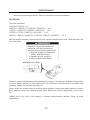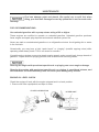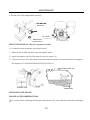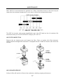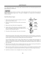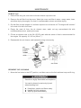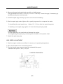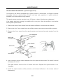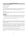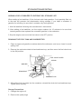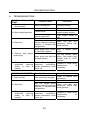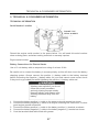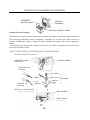
1
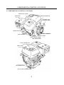
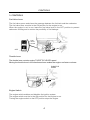
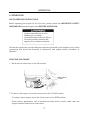
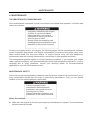
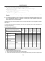
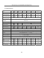
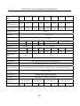
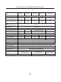
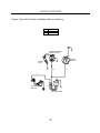
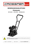
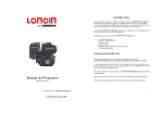
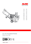
Gasoline Engine Owner’s Manual 160F 168F-1 168F-2 170F 173F 177F 182F 188F 190F G120F·G160F·G180F·G200F·G210F G240F·G270F·G340F·G390F·G420F Keep this owner's manual handy, so you can refer to it at any time. This owner's manual is considered a permanent part of the engine and should remain with the engine if resold. The information and specifications included in this publication were in effect at the time of approval for printing. Only the D Type is equipped for both electric and manual starting. READ THIS OWNER’S MANUAL CAREFULLY. Pay special attention to these symbols and any instructions that follow: Indicates serious injury or death will result if instructions are not followed. Indicates a strong possibility that serious injury or death could result if instructions are not followed. Indicates a possibility that minor injury or an result if instructions are not followed. Indicates that equipment or property damage can result if instructions are not followed. NOTE: Gives helpful information. If a problem should arise, or if you have any questions about your engine, consult your engine dealer. CONTENTS CONTENTS 1. ENGINE SAFETY........................................................................................2 2. COMPONENTS & CONTROL LOCATIONS……………................................................3 3. CONTROLS...............................................................................................4 4. CHECK BEFORE OPERATION .............................................................................. 6 5. OPERATION............................................................................................ 7 6. MAINTENANCE ……………………….......................................................................11 7. STORAGE/TRANSPORTING ...................................................................................23 8. TROUBLESHOOTING………………………………………………................................26 9. TECHNICAL & CONSUMER INFORMATION ……..……………………………………27 10. SPECIFICATIONS ...................................................................................33 11. WIRING DIAGRAMS ...............................................................................36 12. OPTIONAL PARTS....................................................................................38 BATTERY.................................................................................................38 ENGINE SAFETY 1. ENGINE SAFETY IMPORTANT SAFETY INFORMATION Most accidents with engines can be prevented if you follow all instructions in this manual and on the engine. Some of the most common hazards are discussed below, along with the best way to protect yourself and others. Owner Responsibilities z The engines are designed to give safe and dependable service if operated according to instructions. Read and understand this owner’s manual before operating the engine. Failure to do so could result in personal injury or equipment damage. z Know how to stop the engine quickly, and understand the operation of all controls. Never permit anyone to operate the engine without proper instructions. z Do not allow children to operate the engine. Keep children and pets away from the area of operation. Refuel With Care Gasoline is extremely flammable, and gasoline vapor can explode. Refuel outdoors, in a well-ventilated area, with the engine stopped. Never smoke near gasoline, and keep other flames and sparks away. Always store gasoline in an approved container. If any fuel is spilled, make sure the area is dry before starting the engine. Hot Exhaust z The muffler becomes very hot during operation and remains hot for a while after stopping the engine. Be careful not to touch the muffler while it is hot. Let the engine cool before storing it indoors. z To prevent fire hazards and to provide adequate ventilation for stationary equipment applications, keep the engine at least 3 feet (1 meter) away from building walls and other equipment during operation. Do not place flammable objects close to the engine. Carbon Monoxide Hazard Exhaust gas contains poisonous carbon monoxide. Avoid inhalation of exhaust gas. Never run the engine in a closed garage or confined area. Other Equipment Review the instructions provided with the equipment powered by this engine for any additional safety precautions that should be observed in conjunction with engine startup, shutdown, operation, or protective apparel that may be needed to operate the equipment. 2 COMPONENTS & CONTROL LOCATIONS 2. COMPONENTS & CONTROL LOCATIONS THROTTLE LEVER IGNITION SWITCH MUFFLER STARTER GRIP SPARK PLUG RECOIL STARTER AIR CLEANER CHOKE LEVER FUEL VALVE LEVER FUEL FILLER CAP FUEL TANK OIL DRAIN PLUG OIL FILLER CAP/DIPSTICK 3 CONTROLS 3. CONTROLS Fuel Valve Lever The fuel valve opens and closes the passage between the fuel tank and the carburetor. The fuel valve lever must be in the ON position for the engine to run. When the engine is not in use, leave the fuel valve lever in the OFF position to prevent carburetor flooding and to reduce the possibility of fuel leakage. FUEL VALVE LEVER ON OFF OFF Throttle Lever The throttle lever controls engine THROTTLE LEVER speed. Moving the throttle lever in the directions shown makes the engine run faster or slower. THROTTLE LEVER SLOW FAST Engine Switch The engine switch enables and disables the ignition system. The engine switch must be in the ON position for the engine to run. Turning the engine switch to the OFF position stops the engine. 4 CONTROLS ALL ENGINE EXCEPT D TYPE ENGINE SWITCH OFF ON Choke Lever The choke lever opens and closes the choke valve in the carburetor. The CLOSE position enriches the fuel mixture for starting a cold engine. The OPEN position provides the correct fuel mixture for operation after starting, and for restarting a warm engine. Some engine applications use a remotely-mounted choke control rather than the engine-mounted choke lever shown here. CHOKE LEVER OPEN OPEN CLOSE Recoil Starter Grip Pulling the starter grip operates the recoil starter to crank the engine. STARTER GRIP 5 CHECK BEFORE OPERATION 4. CHECK BEFORE OPERATION IS YOUR ENGINE READY TO GO? For your safety, and to maximize the service life of your equipment, it is very important to take a few moments before you operate the engine to check its condition. Be sure to take care of any problem you find, or have your servicing dealer correct it, before you operate the engine. Improperly maintaining this engine, or failing to correct a problem before operation, could cause a malfunction in which you could be seriously injured. Always perform a preoperation inspection before each operation, and correct any problem. Before beginning your preoperation checks, be sure the engine is level and the engine switch is in the OFF position. Check the General Condition of the Engine z z z z Look around and underneath the engine for signs of oil or gasoline leaks. Remove any excessive dirt or debris, especially around the muffler and recoil starter. Look for signs of damage. Check that all shields and covers are in place, and all nuts, bolts, and screws are tightened. Check the Engine Check the engine oil level. Running the engine with a low oil level can cause engine damage. The Oil Alert system (applicable engine types) will automatically stop the engine before the oil level falls below safe limits. However, to avoid the inconvenience of an unexpected shutdown, always check the engine oil level before startup. Check the air filter. A dirty air filter will restrict air flow to the carburetor, reducing engine performance. Check the fuel level. Starting with a full tank will help to eliminate or reduce operating interruptions for refueling. Check the Equipment Powered by This Engine Review the instructions provided with the equipment powered by this engine for any precautions and procedures that should be followed before engine startup. 6 OPERATION 5. OPERATION SAFE OPERATING PRECAUTIONS Before operating the engine for the first time, please review the IMPORTANT SAFETY INFORMATION and the chapter titled BEFORE OPERATION. Carbon monoxide gas is toxic. Breathing it can cause unconsciousness and even kill you. Avoid any areas or actions that expose you to carbon monoxide. Review the instructions provided with the equipment powered by this engine for any safety precautions that should be observed in conjunction with engine startup, shutdown, or operation. STARTING THE ENGINE 1. Move the fuel valve lever to the ON position. FUEL VALVE LEVER ON 2. To start a cold engine, move the choke lever to the CLOSE position. To restart a warm engine, leave the choke lever in the OPEN position. Some engine applications use a remotely-mounted choke control rather than the engine-mounted choke lever shown here. 7 OPERATION CHOKE LEVER OPEN CLOSE 3. Move the throttle lever away from the SLOW position, about 1/3 of the way toward the FAST position. Some engine applications use a remotely-mounted throttle control rather than the engine-mounted throttle lever shown here. SLOW HIGH THROTTLE LEVER 4. Turn the engine switch to the ON position. ENGINE SWITCH OFF ON 5. Operate the starter. RECOIL STARTER (all engine types): Pull the starter grip lightly until you feel resistance, then pull briskly. 8 LOW OPERATION Return the starter grip gently. STARTER GRIP 6. If the choke lever has been moved to the CLOSE position to start the engine, gradually move it to the OPEN position as the engine warms up. CHOKE LEVER OPEN STOPPING THE ENGINE To stop the engine in an emergency, simply turn the engine switch to the OFF position. Under normal conditions, use the following procedure. 1. Move the throttle lever to the SLOW position. Some engine applications use a remotely-mounted throttle control rather than the engine-mounted throttle lever shown here. THROTTLE LEVER SLOW 9 OPERATION 2. Turn the engine switch to the OFF position. ENGINE SWITCH OFF ON 3. Turn the fuel valve lever to the OFF position. FUEL VALVE LEVER OFF SETTING ENGINE SPEED Position the throttle lever for the desired engine speed. Some engine applications use a remotely-mounted throttle control rather than the engine-mounted throttle lever shown here. For engine speed recommendations, refer to the instructions provided with the equipment powered by this engine. THROTTLE LEVER FAST 10 SLOW MAINTENANCE 6. MAINTENANCE THE IMPORTANCE OF MAINTENANCE Good maintenance is essential for safe, economical, and trouble-free operation. It will also help reduce air pollution. Improperly maintaining this engine, or failure to correct a problem before operation, can cause a malfunction in which you can be seriously hurt or killed. Always follow the inspection and maintenance recommendations and schedules in this owner’s manual. To help you properly care for your engine, the following pages include a maintenance schedule, routine inspection procedures, and simple maintenance procedures using basic hand tools. Other service tasks that are more difficult, or require special tools, are best handled by professionals and are normally performed by a technician or other qualified mechanic. The maintenance schedule applies to normal operating conditions. If you operate your engine under unusual conditions, such as sustained high-load or high-temperature operation, or use in unusually wet or dusty conditions, consult your servicing dealer for recommendations applicable to your individual needs and use. MAINTENANCE SAFETY Some of the most important safety precautions are as follows: However, we cannot warn you of every conceivable hazard that can arise in performing maintenance. Only you can decide whether or not you should perform a given task. Failure to properly follow maintenance instructions and precautions can cause you to be seriously hurt or killed. Always follow the procedures and precautions in the owner’s manual. Safety Precautions z Make sure the engine is off before you begin any maintenance or repairs. This will eliminate several potential hazards: 11 MAINTENANCE Carbon monoxide poisoning from engine exhaust. Be sure there is adequate ventilation whenever you operate the engine. Burns from hot parts. Let the engine and exhaust system cool before touching. Injury from moving parts. Do not run the engine unless instructed to do so. z Read the instructions before you begin, and make sure you have the tools and skills required. z To reduce the possibility of fire or explosion, be careful when working around gasoline. Use only a nonflammable solvent, not gasoline, to clean parts. Keep cigarettes, sparks and flames away from all fuel-related parts. Remember that your servicing dealer knows your engine best and is fully equipped to maintain and repair it. To ensure the best quality and reliability, use only new, genuine parts or their equivalents for repair and replacement. MAINTENANCE SCHEDULE REGULAR SERVICE PERIOD Performed at every indicated month or operating hour interval, whichever comes first. ITEM ● ● Engine oil Air cleaner ● Sediment Cup ● Spark plug ● ● ● ● ● Spark arrester (optional parts) Idle speed Valve clearance Fuel tank and strainer Combustion chamber Fuel line Check level Change Check Clean Replace Clean Check-Clean Replace Each use First month or 20 Hrs. Every 3 months or 50 Hrs. Every 6 months or 100 Hrs. Every year or 300 Hrs. ○ ○ ○ ○ ○(1) ○☆ ○ ○ ○ Clean ○ Check-Adjust Check-Adjust Clean Clean Check ○(2) ○(2) ○(2) After every 300 Hrs. (2) Every 2 years (Replace if necessary) (2) Emission-related items. Replace the paper element type only. (1)Service more frequently when used in dusty areas. (2)These items should be serviced by your servicing dealer unless you have the proper tools z ☆ 12 MAINTENANCE and are mechanically proficient. Refer to manual for service procedures. REFUELING Fuel tank capacities 160F(D)/G120F(D): 2.5 L 168F(D)-I / 168F(D)-II / G160F(D) / G200F(D): 3.8 L 170F(D) / 170F(D)-II / G180F(D) / G210F(D): 3.8 L 173F(D) /177F(D) / G240F(D) / G270F(D): 6.0 L 182F(D) / 188F(D) / G340F(D) / G390F(D) /190F(D) / G420F(D): 6.5 L With the engine stopped, remove the fuel tank cap and check the fuel level. Refill the tank if the fuel level is low. Gasoline is highly flammable and explosive. You can be burned or seriously injured when handling fuel. z Stop the engine and keep heat, sparks, and flame away. z Handle fuel only outdoors. z Wipe up spills immediately. MAXIMUM FUEL LEVEL Refuel in a well-ventilated area before starting the engine. If the engine has been running, allow it to cool. Refuel carefully to avoid spilling fuel. Do not fill above the fuel strainer shoulder. After refueling, tighten the fuel tank cap securely. Never refuel the engine inside a building where gasoline fumes may reach flames or sparks. Keep gasoline away from appliance pilot lights, barbecues, electric appliances, power tools, etc. Spilled fuel is not only a fire hazard, it causes environmental damage. Wipe up spills immediately. 13 MAINTENANCE Fuel can damage paint and plastic. Be careful not to spill fuel when filling your fuel tank. Damage caused by spilled fuel is not covered under warranty. FUEL RECOMMENDATIONS Use unleaded gasoline with a pump octane rating of 86 or higher. These engines are certified to operate on unleaded gasoline. Unleaded gasoline produces fewer engine and spark plug deposits and extends exhaust system life. Never use stale or contaminated gasoline or an oil/gasoline mixture. Avoid getting dirt or water in the fuel tank. Occasionally you may hear a light ‘‘spark knock’’ or ‘‘pinging’’ (metallic rapping noise) while operating under heavy loads. This is no cause for concern. If spark knock or pinging occurs at a steady engine speed, under normal load, change brands of gasoline. If spark knock or pinging persists, see an authorized servicing dealer. Running the engine with persistent spark knock or pinging can cause engine damage. Running the engine with persistent spark knock or pinging is considered misuse, and the Distributor’s Limited Warranty does not cover parts damaged by misuse. ENGINE OIL LEVEL CHECK Check the engine oil level with the engine stopped and in a level position. 1. Remove the filler cap/dipstick and wipe it clean. FILLER CAP/DIPSTICK UPPER LIMIT LOWER LIMIT 14 MAINTENANCE 2. Insert and remove the dipstick without screwing it into the filler neck. Check the oil level shown on the dipstick. 3. If the oil level is low, fill to the edge of the oil filler hole with the recommended oil. 4. Screw in the filler cap/dipstick securely. Running the engine with a low oil level can cause engine damage. The Oil Alert system (applicable engine types) will automatically stop the engine before the oil level falls below safe limit. However, to avoid the inconvenience of an unexpected shutdown, always check the engine oil level before startup. ENGINE OIL CHANGE Drain the used oil while the engine is warm. Warm oil drains quickly and completely. 1. Place a suitable container below the engine to catch the used oil, and then remove the filler cap/dipstick and the drain plug. 2. Allow the used oil to drain completely, and then reinstall the drain plug, and tighten it securely. Please dispose of used motor oil in a manner that is compatible with the environment. We suggest you take used oil in a sealed container to your local recycling center or service station for reclamation. Do not throw it in the trash; pour it on the ground; or down a drain. 3. With the engine in a level position, fill to the outer edge of the oil filler hole with the recommended oil. Engine oil capacities: G120F: 0.63 US qt ( 0. 6 L) G160/G200F(D), G160/G200F(D)-B, G160/G200F(D)-C: 0.63 US qt ( 0.60 L) G240/G270/G340/G390/G420F(D), G240/G270F(D)-B: 1.2 US qt ( 1.1 L) G240/G270 F(D)-C, G340/G390F(D)-D: 1.2 US qt ( 1.1 L) Running the engine with a low oil level can cause engine damage. The Oil Alert system (applicable engine types) will automatically stop the engine before the oil level falls below the safe limit. However, to avoid the inconvenience of an unexpected shutdown, fill to the upper limit, and check the oil level regularly. 15 MAINTENANCE 4. Screw in the filler cap/dipstick securely. FILLER CAP/ DIPSTICK OIL LEVEL DRAIN BOLT REDUCTION GEAR OIL (Only on equipped model) <1/2 reduction with automatic centrifugal clutch> 1. Remove the oil filler cap and wipe the dipstick clean. 2. Insert the dipstick into the filler neck but do not screw it in. 3. If the level is low, fill to the upper level mark with the same oil recommended for the engine. Oil capacity of G160/G200/G240/G270F(D)-B: 500 cc DIPSTICK/FILLER CAP UPPER LEVEL DRAIN BOLT SERVICING YOUR ENGINE ENGINE OIL RECOMMENDATIONS Oil is a major factor affecting performance and service life. Use 4-stroke automotive detergent oil. 16 MAINTENANCE SAE 10W-30 is recommended for general use. Other viscosities shown in the chart may be used when the average temperature in your area is within the recommended range. SAE Viscosity Grades AMBIENT TEMPERATURE The SAE oil viscosity and service classification are in the API label on the oil container. We recommend that you use API SERVICE Category SE or SF oil. AIR FILTER INSPECTION Remove the air cleaner cover and inspect the filter. Clean or replace dirty filter elements. Always replace damaged filter elements. If equipped with an oil-bath air cleaner, also check the oil level. PAPER FILTER ELEMENT FILTER FOAM FILTER ELEMENT AIR CLEANER SERVICE A dirty air filter will restrict air flow to the carburetor, reducing engine performance. 17 MAINTENANCE If you operate the engine in very dusty areas, clean the air filter more often than specified in the MAINTENANCE SCHEDULE. Operating the engine without an air filter, or with a damaged air filter, will allow dirt to enter the engine, causing rapid engine wear. This type of damage is not covered by the Distributor’s Limited Warranty. Dual-Filter-Element Types 1. Remove the wing nut from the air cleaner cover, and remove the air cleaner cover. AIR CLEANER COVER 2. Remove the wing nut from the air filter, and remove the filter. PAPER FILTER ELEMENT 3. Remove the foam filter from the paper filter. FOAM FILTER ELEMENT 4. Inspect both air filter elements, and replace them if they are damaged. Always replace the paper air filter element at the scheduled interval. GASKET 5. Clean the air filter elements if they are to be reused. Paper air filter element: Tap the filter element several times on a hard surface to remove dirt, or blow compressed air [not exceeding 30 psi (207 kPa)] through the filter element from the inside. Never try to brush off dirt; brushing will force dirt into the fibers. Foam air filter element: Clean in warm soapy water, rinse, and allow drying thoroughly. Or clean in nonflammable solvent and allow drying. Dip the filter element in clean engine oil, and then squeeze out all excess oil. The engine will smoke when started if too much oil is left in the foam. 6. Wipe dirt from the inside of the air cleaner base and cover, using a moist rag. Be careful to prevent dirt from entering the air duct that leads to the carburetor. 7. Place the foam air filter element over the paper element, and reinstall the assembled air filter. Be sure the gasket is in place beneath the air filter. Tighten the air filter wing nut securely. 8. Install the air cleaner cover, and tighten the cover wing nut securely. 18 MAINTENANCE Oil-Bath Type 1. Remove the wing nut, and remove the air cleaner cap and cover. 2. Remove the air filter from the cover, Wash the cover and filter in warm, soapy water, rinse, and allow drying thoroughly. Or clean in nonflammable solvent and allow drying. 3. Dip the filter in clean engine oil, and then squeeze out all excess oil. The engine will smoke if too much oil is left in the foam. 4. Empty the used oil from the air cleaner case, wash out any accumulated dirt with nonflammable solvent, and dry the case. 5. Fill the air cleaner case to the OIL LEVEL mark with the same oil that is recommended for the engine. Oil capacity: 2.0 US oz (60 cm3 ) 6. Reassemble the air cleaner, and tighten the wing nut securely. WING NUT AIR CLEANER COVER CAP FILTER GRID AIR CLEANER CASE OIL LEVEL SEDIMENT CUP CLEANING 1. Move the fuel valve to the OFF position, and then remove the fuel sediment cup and O-ring. Gasoline is highly flammable and explosive. You can be burned or seriously injured when handling fuel. z z z Keep heat, sparks and flame away. Handle fuel only outdoors. Wipe up spills immediately. 19 MAINTENANCE 2. Wash the sediment cup and O-ring in nonflammable solvent, and dry them thoroughly. 3. Place the O-ring in the fuel valve, and install the sediment cup. Tighten the sediment cup securely. 4. Move the fuel valve to the ON position, and check for leaks. Replace the O-ring if there is any leakage. O-RING SEDIMENT CAP SPARK PLUG SERVICE Recommended spark plugs: F7RTC or other equivalents. An incorrect spark plug can cause engine damage. 1. Disconnect the spark plug cap, and remove any dirt from around the spark plug area. 2. Remove the spark plug with a spark plug wrench. 0.028-0.031 in (0.70-0.80 mm) SPARK PLUG WRENCH 3. Inspect the spark plug. Replace it if the electrodes are worn, or if the insulator is cracked or chipped. 20 MAINTENANCE 4. Measure the spark plug electrode gap with a suitable gauge. The gap should be 0.028 in -0.031 in (0.70 mm - 0.80 mm). Correct the gap, if necessary, by carefully bending the side electrode. 5. Install the spark plug carefully, by hand, to avoid cross-threading. 6. After the spark plug seats, tighten with a spark plug wrench to compress the water. If reinstalling the used spark plug ,tighten 1/8 - 1/4 turn after the spark plug seats. If installing a new spark plug, tighten 1/2 turn after the spark plug seats. A loose spark plug can overheat and damage the engine. Over tightening the spark plug can damage the threads in the cylinder head. 7. Attach the spark plug cap. IDLE SPEED ADJUSTMENT 1. Start the engine outdoors, and allow it to warm up to operating temperature. 2. Move the throttle lever to its slowest position. 3. Turn the throttle stop screw to obtain the standard idle speed. Standard idle speed: 1,400±150 rpm THROTTLE STOP SCREW 21 MAINTENANCE SPARK ARRESTER SERVICE (optional equipment) Your engine is not factory-equipped with a spark arrester. In some areas, it is illegal to operate an engine without a spark arrester. Check local laws and regulations. A spark arrester is available from authorized servicing dealers. The spark arrester must be serviced every 100 hours to keep it functioning as designed. If the engine has been running, the muffler will be very hot. Allow the muffler to cool before servicing the spark arrester. 1. Remove the three 4 mm screws from the exhaust deflector, and remove the deflector. 2. Remove the four 5 mm screws from the muffler protector and remove the muffler protector. 3. Remove the 4 mm screw from the spark arrester, and remove the spark arrester from the muffler. 5mm SCREWS MUFFLER PROTECTOR 4mm SCREW MUFFLER SPARK ARRESTER SCREEN GASKET 8mm NUTS 4. Use a brush to remove carbon deposits from the spark arrester screen. Be careful to avoid damaging the screen. The spark arrester must be free of breaks and holes. Replace the spark arrester if it is damaged. 5. Install the spark arrester, muffler protector, and exhaust deflector in the reverse order of disassembly. 22 STORAGE/TRANSPORTING 7. STORAGE/ TRANSPORTING STORING YOUR ENGINE Storage Preparation Proper storage preparation is essential for keeping your engine trouble free and looking good. The following steps will help to keep rust and corrosion from impairing your engine’s function and appearance, and will make the engine easier to start after storage. Cleaning If the engine has been running, allow it to cool for at least half an hour before cleaning. Clean all exterior surfaces, touch up any damaged paint, and coat other areas that may rust with a light film of oil. z Using a garden hose or pressure washing equipment can force water into the air cleaner or muffler opening. Water in the air cleaner will soak the air filter, and water that passes through the air filter or muffler can enter the cylinder, causing damage. z Water contacting a hot engine can cause damage. If the engine has been running, allow it to cool for at least half an hour before washing. Fuel Gasoline will oxidize and deteriorate in storage. Old gasoline will cause hard starting, and it leaves gum deposits that clog the fuel system. If the gasoline in your engine deteriorates during storage, you may need to have the carburetor and other fuel system components serviced or replaced. The length of time that gasoline can be left in your fuel tank and carburetor without causing functional problems will vary with such factors as gasoline blend, your storage temperatures, and whether the fuel tank is partially or completely filled. The air in a partially filled fuel tank promotes fuel deterioration. Very warm storage/temperatures accelerate fuel deterioration. Fuel deterioration problems may occur within a few months, or even less if the gasoline was not fresh when you filled the fuel tank. The Distributor’s Limited Warranty does not cover fuel system damage or engine performance problems resulting from neglected storage preparation. You can extend fuel storage life by adding a fuel stabilizer that is formulated for that purpose, or you can avoid fuel deterioration problems by draining the fuel tank and carburetor. 23 STORAGE/TRANSPORTING ADDING A FUEL STABILIZER TO EXTEND FUEL STORAGE LIFE When adding a fuel stabilizer, fill the fuel tank with fresh gasoline. If only partially filled, air in the tank will promote fuel deterioration during storage. If you keep a container of gasoline for refueling, be sure that it contains only fresh gasoline. 1. Add fuel stabilizer following the manufacturer’s instructions. 2. After adding a fuel stabilizer, run the engine outdoors for 10 minutes to be sure that treated gasoline has replaced the untreated gasoline in the carburetor. 3. Stop the engine, and move the fuel valve to the OFF position. DRAINING THE FUEL TANK AND CARBURETOR 1. Place an approved gasoline container below the carburetor, and use a funnel to avoid spilling fuel. 2. Remove the carburetor drain bolt and sediment cup, and then move the fuel valve lever to the ON position. FUEL VALVE LEVER O-RING WASHER DRAIN BOLT SEDIMENT CUP 3. After all the fuel has drain into the container, reinstall the drain bolt and sediment cup. Tighten them securely. Storage Precautions 1. Change the engine oil. 2. Remove the spark plugs. 24 STORAGE/TRANSPORTING 3. Pour a tablespoon (5-10 cc) of clean engine oil into the cylinder. 4. Pull the starter rope several times to distribute the oil in the cylinder. 5. Reinstall the spark plugs. 6. Pull the starter rope slowly until resistance is felt. This will close the valves so moisture cannot enter the engine cylinder. Return the starter rope gently. If your engine will be stored with gasoline in the fuel tank and carburetor, it is important to reduce the hazard of gasoline vapor ignition. Select a well-ventilated storage area away from any appliance that operates with a flame, such as a furnace, water heater, or clothes dryer. Also avoid any area with a spark-producing electric motor, or where power tools are operated. If possible, avoid storage areas with high humidity, because that promotes rust and corrosion. Unless all fuel has been drained from the fuel tank, leave the fuel valve lever in the OFF position to reduce the possibility of fuel leakage. Position the equipment so the engine is level. Tilting can cause fuel or oil leakage. With the engine and exhaust system cool, cover the engine to keep out dust. A hot engine and exhaust system can ignite or melt some materials. Do not use sheet plastic as a dust cover. A nonporous cover will trap moisture around the engine, promoting rust and corrosion. If equipped with a battery for an electric starter, recharge the battery once a month while the engine is in storage. This will help to extend the service life of the battery. Removal from Storage Check your engine as described in the chapter CHECK BEFORE OPERATION. If the fuel was drained during storage preparation, fill the tank with fresh gasoline. If you keep a container of gasoline for refueling, be sure that it contains only fresh gasoline. Gasoline oxidizes and deteriorates over time, causing hard starting. If the cylinders were coated with oil during storage preparation, the engine may smoke briefly at startup. This is normal. TRANSPORTING If the engine has been running, allow it to cool for at least 15 minutes before loading the engine-powered equipment on the transport vehicle. A hot engine and exhaust system can burn you and can ignite some materials. Keep the engine level when transporting to reduce the possibility of fuel leakage. Move the fuel valve lever to the OFF position. 25 TROUBLESHOOTING 8. TROUBLESHOOTING ENGINE WILL START 1. Electric starting: check battery NOT 2. Check control positions Possible Cause Battery discharged. Recharge battery. Fuel valve OFF. Move lever to ON. Move lever to CLOSE unless engine is warm. Turn engine switch to ON. Refuel Choke OPEN. Engine switch OFF. 3. Check fuel. Correction Out of fuel. Bad fuel; engine stored Drain fuel tank and without treating or draining carburetor. Refuel with gasoline, or refueled with fresh gasoline. bad gasoline. Spark plugs faulty, fouled, Gap, or replace spark or improperly gapped. plugs. 4. Remove and inspect Dry and reinstall spark spark plugs. Spark plugs wet with fuel plugs. Start engine with (flooded engine). throttle lever in FAST position. 5. Take engine to an Fuel filter clogged, Replace or repair faulty authorized servicing carburetor malfunction, components as dealer, or refer to ignition malfunction, valve necessary. manual. stuck, etc. ENGINE LACKS POWER Possible Cause 1. Check air filter Filter element(s) clogged. Out of fuel. 2. Check fuel. 3. Take engine to an authorized servicing dealer, or refer to manual. Correction Clean or replace filter element(s). Refuel Bad fuel; engine stored Drain fuel tank and without treating or draining carburetor. Refuel with gasoline, or refueled with fresh gasoline. bad gasoline. Fuel filter clogged, Replace or repair faulty carburetor malfunction, components as ignition malfunction, valve necessary. stuck, etc. 26 TECHNICAL & CONSUMER INFORMATION 9. TECHNICAL & CONSUMER INFORMATION TECHNICAL INFORMATION Serial Number Location ENGINE TYPE SERIAL NUMBER Record the engine serial number in the space below. You will need this serial number when ordering parts, and when making technical or warranty inquires. Engine serial number: Battery Connections for Electric Starter Use a 12-volt battery with an ampere-hour rating of at least 18 Ah. Be careful not to connect the battery in reverse polarity, as this will short circuit the battery charging system. Always connect the positive (+) battery cable to the battery terminal before connecting the negative (-) battery cable, so your tools cannot cause a short circuit if they touch a grounded part while tightening the positive (+) battery cable end. A battery can explode if you do not follow the correct procedure, seriously injuring anyone nearby. Keep all sparks, open flames, and smoking materials away from the battery. 1. Connect the battery positive (+) cable to the starter solenoid terminal as shown. 2. Connect the battery negative (-) cable to an engine mounting bolt, frame bolt, or other good engine ground connection. 3. Connect the battery positive (+) cable to the battery positive (+) terminal as shown. 4. Connect the battery negative (-) cable to the battery negative (-) terminal as shown. 5. Coat the terminals and cable ends with grease. 27 TECHNICAL & CONSUMER INFORMATION NEGATIVE(-) BATTERY CABLE STARTER SOLENOID POSITIVE(+) BATTERY CABLE Remote Control Linkage The throttle and choke control levers are provided with holes for optional cable attachment. The following illustrations show installation examples for a solid wire cable and for a flexible, braided wire cable. If using a flexible, braided wire cable, add a return spring as shown. It is necessary to loosen the throttle lever friction nut when operating the throttle with a remotely-mounted control. G120F, G160/G200F(D), G160/G200F(D)-B, G160/G200F(D)-C: REMOTE THROTTLE LINKAGE RETURN SPRING THROTTLE LEVER PIVOT NUT Flexible wire core mounting 4mm SCREW WIRE Solid wire core mounting WIRE HOLDER OPTIONAL THROTTLE LEVER 5 mm CIRCLIP REMOTE CHOKE LINKAGE WIRE HOLDER CHOKE LEVER 28 TECHNICAL & CONSUMER INFORMATION G240/G270/G340/G390/G420F(D), G240/G270F(D)-B, G340/G390F(D)-D: REMOTE THROTTLE LINKAGE RETURN SPRING THROTTLE LEVER PIVOT NUT Flexible wire core mounting 4mm SCREW WIRE HOLDER WIRE OPTIONAL THROTTLE LEVER Solid wire core mounting 5 mm CIRCLIP REMOTE CHOKE LINKAGE WIRE HOLDER CHOKE LEVER Carburetor Modification for High Altitude Operation At high altitude, the standard carburetor air-fuel mixture will be too rich. Performance will decrease, and fuel consumption will increase. A very rich mixture will also foul the spark plug and cause hard starting. Operation at an altitude that differs from that at which this engine was certified, for extended periods of time, may increase emissions. High altitude performance can be improved by specific modifications to the carburetor. If you always operate your engine at altitudes above 5,000 feet (1,500 meters), have your servicing dealer perform this carburetor modification. This engine, when operated at high altitude with the carburetor modifications for high altitude use, will meet each emission standard throughout its useful life. 29 TECHNICAL & CONSUMER INFORMATION Even with carburetor modification, engine horsepower will decrease about 3.5% for each 1,000-foot (300-meter) increase in altitude. The effect of altitude on horsepower will be greater than this if no carburetor modification is made. When the carburetor has been modified for high altitude operation, the air-fuel mixture will be too lean for low altitude use. Operation at altitudes below 5,000 feet (1,500meters) with a modified carburetor may cause the engine to overheat and result in serious engine damage. For use at low altitudes, have your servicing dealer return the carburetor to original factory specifications. Oxygenated Fuels Some conventional gasolines are being blended with alcohol or an ether compound. These gasolines are collectively referred to as oxygenated fuels. To meet clean air standards, some areas use oxygenated fuels to help reduce emissions. If you use an oxygenated fuel, be sure it is unleaded and meets the minimum octane rating requirement. Before using an oxygenated fuel, try to confirm the fuel’s contents. Some areas require this information to be posted on the pump. The following are the EPA approved percentages of oxygenates: ETHANOL ––––––––(ethyl or grain alcohol) 10% by volume You may use gasoline containing up to 10% ethanol by volume. Gasoline containing ethanol may be marketed under the name ‘‘Gasohol’’. MTBE ––––––––––––(methyl tertiary butyl ether) 15% by volume You may use gasoline containing up to 15% MTBE by volume. METHANOL ––––––(methyl or wood alcohol) 5% by volume You may use gasoline containing up to 5% methanol by volume, as long as it also contains cosolvents and corrosion inhibitors to protect the fuel system. Gasoline containing more than 5% methanol by volume may cause starting and/or performance problems. It may also damage metal, rubber, and plastic parts of your fuel system. If you notice any undesirable operating symptoms, try another service station, or switch to another brand of gasoline. Fuel system damage or performance problems resulting from the use of an oxygenated fuel containing more than the percentages of oxygenates mentioned above are not covered under warranty. Emission Control System Information 30 TECHNICAL & CONSUMER INFORMATION Source of Emissions The combustion process produces carbon monoxide, oxides of nitrogen, and hydrocarbons. Control of hydrocarbons and oxides of nitrogen is very important because, under certain conditions, they react to form photochemical smog when subjected to sunlight. Carbon monoxide does not react in the same way, but it is toxic. This utilizes lean carburetor settings and other systems to reduce the emissions of carbon monoxide, oxides of nitrogen and hydrocarbons. Tampering and Altering Tampering with or altering the emission control system may increase emissions beyond the legal limit. Among those acts that constitute tampering are: z z Removal or alteration of any part of the intake, fuel or exhaust systems. Altering or defeating the governor linkage or speed-adjusting mechanism to cause the engine to operate outside its design parameters. Problems That May Affect Emissions If you are aware of any of the following symptoms, have your engine inspected and repaired by your servicing dealer. z z z z z Hard starting or stalling after starting. Rough idle. Misfiring or backfiring under load. Afterburning (backfiring). Black exhaust smoke or high fuel consumption. Replacement Parts The emission control systems on your engine were designed, built. We recommend the use of genuine parts whenever you have maintenance done. These original-design replacement parts are manufactured to the same standards as the original parts, so you can be confident of their performance. The use of replacement parts that are not of the original design and quality may impair the effectiveness of your emission control system. A manufacturer of an aftermarket part assumes the responsibility that the part will not adversely affect emission performance. The manufacturer or rebuilder of the part must certify that use of the part will not result in a failure of the engine to comply with emission regulations. Maintenance Follow the maintenance schedule. Remember that this schedule is based on the assumption that your machine will be used for its designed purpose. Sustained high-load 31 TECHNICAL & CONSUMER INFORMATION or high-temperature operation, or use in unusually wet or dusty conditions, will require more frequent service. Engine Tune-up ITEM SPECIFICATION Spark plug gap 0.028-0.031 in (0.70 mm -0.80 mm) Valve clearance IN: 0.15 mm±0.02 mm (cold) EX: 0.20 mm±0.02 mm (cold) Other specifications No other adjustments needed CONSUMER INFORMATION Publications These publications will give you additional information for maintaining and repairing your engine. You may order them from your engine dealer. Parts Catalog This manual provides complete, illustrated parts lists. QUICK REFERENCE INFORMATION Type Engine Oil Spark Plug Carburetor Maintenance Capacity Type Gap Idle speed Each use First 20 hours Subsequent SAE 10W-30,API SE or SF, for general use G120F: 0.6 L G160/G200F(D):0.6 L G240/G270F(D):1.1L G340/G390/G420F(D):1.1 L F7RTC or other equivalents. 0.028-0.031 in (0.70 mm-0.80 mm) 1400 rpm±150 rpm Check engine oil. Check air filter. Change engine oil. Refer to the maintenance 32 TECHNICAL & CONSUMER INFORMATION 10. Specifications Model Type Rated power(kW/3600rpm) Max. torque(N·m/rpm) G120F G160F(D) G200F(D) G160F(D)-B G200F(D)-B G160F(D)-C G200F(D)-C Single cylinder, 4-Stroke, Forced Air Cooling, OHV 2.5 3.1 3.8 3.1 3.8 3.1 3.8 7.5 3000 10.5 3000 13 3000 20 1500 22 1500 20 1500 24 1500 Fuel consumption(g/kW·h) ≤395 1400±150 Idle speed SpeedFluctuating Ratio ≤10% Transmission Mode - - - Reduction Ratio - - - Clutch Mode Chain mode 2:1 Noise(≤) 70db(A) Bore×Stroke(mm) 60×42 68×45 68×54 68×45 68×54 68×45 68×54 Displacement(cc) 118 163 196 163 196 163 196 Compression Ratio 8.5:1 Splash Recoil start( Recoil start / Electric starting) Anti-clockwise(from P.T.O. side) input valve:0.10 mm ~0.15mm, output valve:0.15 mm ~0.20mm 0.7 mm ~0.8mm Transistorized magneto Ignition Semi-dry, Oil bath, Foam filter Lubricating mode Starting Mode Rotation Valve Clearance Spark plug clearance Igniting Mode Air cleaner Dimension(Length) (mm) Dimension(Width) (mm) Dimension(High) (mm) Net weight(kg) 305 312 312 391 391 342 342 341 362 376 362 376 362 376 318 335 335 335 335 335 335 13 15(18) 16(19) 19(22) 20(23) 15.5(18.5) 16.5(19.5) 33 TECHNICAL & CONSUMER INFORMATION Model G180F(D) G210F(D) G240F(D) G270F(D) G240F(D)-B G240F(D)-C G270F(D)-C Single cylinder, 4-Stroke, Forced Air Cooling, OHV Type Rated power(kW/3600rpm) Max. torque(N·m/rpm) 3.2 4.0 5.1 5.8 5.1 5.8 5.1 5.8 11 3000 13 3000 16.5 3000 19 3000 32 1500 37 1500 32 1500 37 1500 Fuelconsumption( g/kW·h) ≤395 1440±150 Idle speed Speed Ratio G270F(D)-B Fluctuating ≤10% Transmission Mode - - Reduction Ratio - - Noise(≤) Clutch Mode Chain Mode 2:1 70 db(A) 80 db(A) Bore×Stroke(mm) 70×46 70×55 73×58 77×58 73×58 77×58 73×58 77×58 Displacement(cc) 177 212 242 270 242 270 242 270 Compression Ratio 8.5:1 8.2:1 Splash Lubricating mode Recoil start( Recoil start / Electric starting) Starting Mode Anti-clockwise(from P.T.O. side) Rotation Valve Clearance Spark clearance input valve:0.10 mm ~0.15mm, plug 0.7 mm ~0.8mm Transistorized magneto Ignition Igniting Mode Semi-dry, Oil bath, Foam filter Air cleaner Dimension(L×W× H) (mm) Net weight(kg) output valve:0.15 mm ~0.20mm 342×376×335 16(19) 17(20) 380×430×410 25(28) 26(29) 34 440×430×410 29(32) 30(33) 405×430×410 28(31) 29(32) TECHNICAL & CONSUMER INFORMATION Model G340F(D) Type Rated power(kW/3600rpm) Max. torque(N·m/rpm) G390F(D) G340F(D)-D G390F(D)-D G420F(D) Single cylinder, 4-Stroke, Forced Air Cooling, OHV 7 8.3 7 8.3 8.5 23.5 3000 26.5 3000 45 1500 50 1500 28 3000 Fuel consumption(g/kW·h) ≤395 1440±150 Idle speed Speed Fluctuating Ratio ≤10% Transmission Mode - - Gear transmission Reduction Ratio - - 2:1 Noise(≤) 80 db(A) Bore×Stroke(mm) 82×64 88×64 82×64 88×64 90×66 Displacement(cc) 337 389 337 389 420 Compression Ratio 8:1 Lubricating mode Splash Starting Mode Recoil start( Recoil start / Electric starting) Rotation Valve Clearance Anti-clockwise(from P.T.O. side) input valve:0.10 mm ~0.15mm, output valve:0.15 mm ~0.20mm Spark plug clearance 0.7 mm ~0.8mm Igniting Mode Air cleaner Dimension(L×W×H) (mm) Net weight (kg) 8.3:1 Transistorized magneto Ignition Semi-dry, Oil bath, Foam filter 405×450×443 440×450×443 405×452×443 31(34) 33(36) 32(35) 35 WIRING DIAGRAMS 11. Wiring Diagrams ENGINE SWITCH IG E OFF O O ON START ST BAT O O Bl Y W BLACK YELLOW WHITE Br R G BROWN RED GREEN STARTER MOTOR BATTERY STARTER SOLENOID CHARGING COIL Bl/W RECTIFIER W FUSE Br W TRANSISTORIZED IGNITION UNIT Bl Br ENGINE SWITCH W Bl CIRCUIT BREAKER Bl SPARK PLUG W W Y Y OIL LEVEL SWITCH Bl OIL ALERT UNIT CONTROL BOX 36 WIRING DIAGRAMS Engine Type with Oil Alert and Without Electric Starting Bl Y G BLACK YELLOW GREEN TRANSISTORIZED IGNITION UNIT ENGINE SWITCH SPARK PLUG Bl Y OIL LEVEL SWITCH Bl Y OIL ALERT UNIT 37 Y OPTIONAL PARTS 12. OPTIONAL PARTS BATTERY Use a battery rated at 12V, 18Ah or more. UPPER LEVEL Do not reverse polarity. Serious damage to the engine and/or battery may occur. LOWER LEVEL A battery can explode if you do not follow the correct procedure, seriously injuring anyone nearby. Keep all sparks, open flames, and smoking materials away from the battery. Check the electrolyte level to be sure that it is between the marks on the case. If the level is below the lower mark, remove the caps and add distilled water to bring the electrolyte level to the upper mark. The cells should be equally full. 38