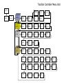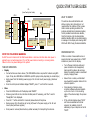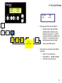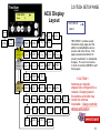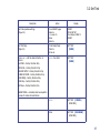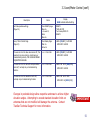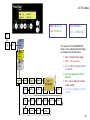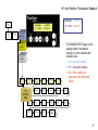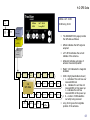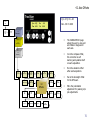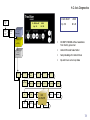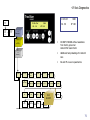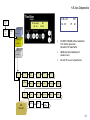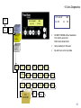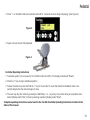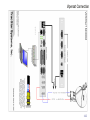
1
The most important thing we build is trust. Cobham SATCOM TracStar Antenna Control System Advanced VSAT Operations Guide Version 4.1 TracStar Systems, Inc. dba Cobham SATCOM 1551 College Park Business Center Road • Orlando, FL • 32804 Ph: 407-650-9054 • Fax: 407-650-9086 • www.cobham.com/satcom !! CAUTION !! Antennas are typically shipped fully configured for a network. Changing data in the antenna controller may render the antenna inoperable. Change controller settings with caution. 1 TracStar Controller Menu Grid Powerup Please Wait Monitor Check Please Wait Rev 2.6x Motorized Drive Feed ONLY 1.3 POL Loading Please Wait 1.4 GPS 1.5 Compass Rev 2.2x 1.1 Set Ref Satellite 1.2 Set Data Satellite 2.0 User Setup 2.1 Jog Page 2.2 Satellite Parameter 3.0 Tech Setup 3.1 Set Option 3.2 Set Test 1.0 Ready Page 3.6 Az Stow 4.0 Diagnostic 3.7 Geographical Area 4.A Axis Angles 4.B Factory Only 4.F Position Data 4.G GPS Data 1.3 GPS 2.3 Ref Sat 3.3 Level/Motor 1.4 Compass 2.4 VS / Lock 3.4 Modem/ Antenna / Polarity 2.5 Inclined Orbit Optional S/W 3.5 Move/RF Safe 3.8 LNB Gain 4.C Modem 4.H Zero Resets 4.D Scan Hits 4.E Tilt Angles 4.I Offsets 4.J Scan Width 4.L azEr 4.M elEr 4.N plEr 4.O Az>EncSF 4.R El>psf 4.S Pl>EncSF 4.T Pl>psf 4.U Axis Base Tilt 4.P Az>psf 4.K SFE SFR 4.Q El>EncSF Data Is Subject To Change Without Notice This document is supplied as and intended to be a reference document for TracStar Systems product users. The document is periodically updated and may contain data that does not apply to a user’s specific product or is obsolete. If questions exist regarding the applicability of the data relative to your product, contact TracStar Technical Support. This manual and its contents are considered proprietary intellectual property of TracStar Systems, Inc. Unauthorized use or distribution is specifically prohibited. Contents are protected by law. © Copyright 2010 TracStar Systems, Inc. All rights reserved. TracStar Systems is a registered trademark of Cobham, PLC. Roto-Lok® is a registered trademark of Sagebrush Technologies Any and all additional product names referred to in this manual may be trademarks or registered trademarks of their respective companies. Such trademarks are the sole property of their respective owners. Table of Contents QUICK START USER GUIDE Using the Antenna Content Information Using the Manual BASIC Theory of Operation DirectPointTM Theory of Operation IFL Cable Connections Antenna Setup Options 1. Quick Setup Reference – Known Reference Satellites - CONUS 2. Quick Setup Reference – Known Reference Satellites – NON CONUS 3. Quick Setup - From a Script 4. Quick Setup - SkyScan User Manual Data Presentation and ACU Operation TracStar Controller Display and Layout 6 7 8 9 10 11 12 13 14 15 16 17 18 19 1.0 READY PAGE 1.0 Typical Acquisition Sequence DirectPoint – Typical Acquisition Process 1.1 Set Reference Satellite 1.2 Select Data Satellite 1.3 Polarity 1.4 Manual GPS Input 1.5 Manual Compass Input 20 21 22 23 25 27 29 31 2.0 USER SETUP PAGE 2.1 Jog 2.2 Satellite Parameters 2.3 Reference Satellite 2.4 VS/Lock Methods 33 34 36 38 41 3.0 TECH SETUP PAGE 3.1 Set Option 3.2 Set Test 3.3 Level/Motor Control Page 3.4 Select Modem/Antenna/Pol 3.5 Move/RF_SAFE 3.6 Azimuth Stow/External Switch 3.7 USAdvb 3.8 LNB GAIN 44 46 47 49 51 53 55 57 59 4.0 DIAGNOSTICS PAGE 4.A Axis Angles 4.B B Page 4.C C Page 4.D Scan Hits 4.E Tilt Angles 4.F Axis Position Transducer Readout 4.G GPS Data 4.H Axis Zero Offsets 4.I Axis Offsets 4.J Azimuth Scan Width 4.K SFE SFR 4.L Axis Diagnostics 4.M Axis Diagnostics 4.N Axis Diagnostics 4.O Axis Diagnostics 4.P Axis Diagnostics 4.Q Axis Diagnostics 4.R Axis Diagnostics 4.S Axis Diagnostics 4.T Axis Diagnostics 4.U Axis Diagnostics 61 62 63 64 65 66 67 68 69 70 72 74 75 76 77 78 79 80 81 82 83 84 4 Table of Contents (cont.) TROUBLESHOOTING 85 ERROR MESSAGES & RECOVERY 86 Pedestal Preventative Maintenance 87 Pedestal 88 Appendix A – Connection Directions External Stow Monitoring – Vehicle Mounting Gilat 360E Connection SkyEdge Connection Connexstar Cisco Bruno (Gilat) EMS Technologies Connection EMS with EdgeAccess Connection iDirect Netmodem II Connection Avaya G350 Switch Connection EMS & TracStar Gateway iDirect NetModem II iDirect 3000 Series Connection Linkstar Connection Vipersat Connection ViaSat Surf Beam Connection System Integration Example TracStar Control Cable Console and Cross Over Cable Schema TracStar Controller Menu Grid Product Certifications 99 100 101 102 103 104 105 106 107 108 109 110 111 112 113 114 115 116 117 118 Appendix B – Inclined Orbit Satellite Tracking by TLE 119 Appendix C – TSS6P Quick Start User Guide v1.1 124 5 QUICK START USER GUIDE IFL (Inter Facility Link Cable) IDU ODU BUC GPS COMPASS LNB WHAT TO EXPECT TX – (RED) P E D E S T A L ACU ANT MOD PC IDD 50-60 Hz 110-220V AC Single Phase Controller / Power BASE SAT MODEM TX SERIAL RX PWR LAN EQUIPMENT DISPLAY UNIT The antenna has a self-calibration and startup routine. User intervention is not required after the initiation of this process. Under normal operating conditions the antenna will determine its absolute location, find its predetermined reference satellite, then find and lock onto the desired data satellite. Satellite LOCK can be determined by a message on the display unit showing LOCK XXX.X with XXX.X being the desired satellite. RX – (BLUE) NOTE THE FOLLOWING WARNING Do NOT connect or disconnect the RG6 Coaxial cables or antenna controller cable while power is applied to any connected equipment. Turn off all power before connecting or removing cables. Failure to do so may cause damage to the system. TURN KEY OPERATION Deploy Connect antenna as shown above. (The MOD-SERIAL cable is required for modems using GPS input. It may be a DB9-DB9 or a DB9-RJ45 w/a RJ45 jumper cable, depending on modem style.) Apply power from the tabletop power supply or the 1U rack mount power supply (whichever applies). Once the control panel interface displays “READY”, press “+” and hold for 2 seconds. Stow Press the MAIN button until the display reads “READY”. Observe green LEDs on the controller interface panel. If necessary, push “Run” once for “Ready/Idle” to be displayed. Press the “-” button and hold for 2 seconds; allow antenna to fully stow. Remove power from the antenna by turning off power to the power supply or the 1U rack mount panel (whichever applies). Once power is removed, disconnect any cables necessary for transporting the antenna. PERFORMANCE TIPS If after a number of unsuccessful scans or several minutes have passed and no “LOCK” indication is present on the display: Turn off power and check cable and power connections to all equipment, being careful to observe all warnings. Ensure the satellite modem is connected properly. Reapply Power. Ensure there is a clear, unobstructed view towards the equator relative to the antenna’s position. Check leveling of antenna. Autocorrection software will accommodate up to ±10o of error in the mounting plane of the antenna. Begin the process again. If the controller display shows “LOCK” and Voice is available and Internet access is not available, check IP addressing of your computer and set to “DHCP”. 6 Using the Antenna The TracStar control system is resident on the antenna. No data is stored in the controller’s ACU (Antenna Control Unit). The Indoor Display (IDD) with the ‘Blue Box’ or the 1RU controller interface serve as I/O devices for the user’s antenna system. NOTE: The IDD unit (or handheld display) was primarily designed to be used indoors in place of the ACU if there is a need for remote control or monitoring of the system. The IDD is not waterproof and should not be left outside in the rain. Antenna Control Unit (ACU) The desktop controller’s IDD and the 1RU rack-mount controller serve as controller interface devices to the antenna-based TracStar control system. OR TracStar Controller System 7 Content Information 1. Basic Connectivity Information 2. Basic Theory of Operation 3. Antenna Setup Options 4. Antenna Operations and Display Unit Instructions 5. Connection information & diagrams for various modems and configurations 8 Using the Manual IMPORTANT Arrow 1x Main 2x Identifies information that TracStar feels is important for product operation. Represents ACU navigational instruction, which means: [n]x = Number of times to press the ACU button to access a specific Display Page. For example, “Main 2x” means press the Main button two times to display the Tech Setup page. 9 BASIC Theory of Operation Antenna Description Three axis, polarization over elevation over azimuth Configurable for operation on most satellites Designed for simple operation, performs precise antenna to satellite alignment with the push of a button or a switch Pedestal Description: High precision motors with optical encoders Very low backlash drive system Each antenna is fully integrated with GPS Compass DVB Receiver Base level sensor Antenna Control System with User Interface The Standard Satellite Acquisition Process Upon power up and deployment, the following acquisition sequence takes place: Compass aligns the antenna with south (if in the northern hemisphere, to the north if in the southern hemisphere) Antenna acquires GPS for high precision geographic location information Antenna precisely sets elevation angle and sweeps through a selected reference satellite, monitoring signal characteristics of the reference satellite Antenna peaks on reference satellite until the center of the antenna beam is located as an alignment reference. Antenna then peaks on the satellite of interest and performs a high precision alignment to the satellite Antenna sends GPS to satellite modem (if applicable) Satellite modem initiates contact with network operations center 10 Theory of Operation Antenna Description DirectPointTM technology closely couples with the satellite modem, thus enhancing the satellite acquisition accuracy and reducing the startup time. The antenna goes directly to the data satellite and, using enhanced communications capability with intelligent modems, is able to acquire, lock, and peak on the specific satellite without the traditional prealignment (reference satellite) stage. The DirectPoint mode is invoked by setting “10000” as the LOCK method word (see 2.4 VS/Lock Methods) and selecting “iDirect” (or other two-way communication modem) as the MODEM (see 3.4 Select Modem/Antenna/Pol). DirectPoint Acquisition Description Upon power up and deployment, the following acquisition sequence takes place: Compass aligns the antenna with south (if in the northern hemisphere, to the north if in the southern hemisphere) Antenna acquires GPS data for high precision geographic location information Using DirectPointTM and bypassing the selected reference satellite, the antenna pointing algorithm precisely scans to the selected data satellite Monitoring signal characteristics specific to this data satellite, the antenna peaks on the center of the satellite beam and performs a high precision alignment to this satellite After completion of the peaking sequence GPS data is sent to the modem to enable transmit The modem can then automatically initiate contact with the network operations center and be commissioned into the network 11 IFL Cable Connections There are two different types of coaxial connectors on the IFL cables. The cable connecting to the antenna is shown below. The two-piece connection allows for the O-ring seal in the smaller nut to be placed on the F-type connector first. Once the cable is connected, the smaller nut is tightened against the cable end allowing the Oring to provide a moisture proof seal. TRANSMIT RECEIVE 12 Antenna Setup Options 1. Quick Setup This setup is performed for an antenna system to be used in a geographical region for the first time. The user has known Reference Satellite information. The user does not have Reference Satellite frequencies. 2. Quick Setup Reference from Script This setup is performed for an antenna system to be used in a geographical region for the first time. The user has a script (that is, orbital positions and frequencies exist for the Reference Satellites and therefore can be entered into the antenna controller). 3. Quick Setup Reference Using SkyScan This setup is performed for an antenna system to be used in a geographical region for the first time. There is no information for Reference Satellites. 4. After the Reference Satellites are input, the following criteria should be considered in selecting them: There can be up to 12 Reference Satellites in the library. A general rule is to select 3 to 4. The antenna “rated” the satellites during the ScanSky. Reference satellite positions ending with the letter “A” are the most desirable, then “B”, then “C”. “Z” indicates that sufficient carrier power was not found. Try to select satellites that are low in the orbital ARC (east or west of the user’s longitude position); i.e., lower on the horizon is better. 13 1. Quick Setup Reference – Known Reference Satellites - CONUS IMPORTANT NOTE: The factory default setting for Reference Satellite is AUTO. The system will select a reference satellite that is optimum for your GPS position. Locate the antenna so that it has an unobstructed view of the orbital arc. Step Function Action Display Page 1. Power up antenna Turn on power at ACU READY 2. Set Code (enables editing) (Page 3.0) From READY page Main 2x + to code 13, Enter Main 2x READY TECH SETUP,[Code 0] Tech Setup [CODE 13] READY 3. (Input Reference Satellites Page 1.1) Select Ref 61.5 Satellite Select Ref 119.0 Satellite From Ready page: Arrow 1x + or – through Ref Sat List ENTER + or – through Ref Sat List Enter Main READY SetREF, 61.5 XXX.X SetREF, 119.0 XXX.X From READY page: Arrow 2x + or – + or – Enter READY SELECT DATA [SatA] or [SatB] XXX.X Factory Default is AUTO 4. (Input data satellite parameters Page 1.2) Toggle between SatA and SatB Input orbital position for SatA Input orbital position for SatB READY Orient the antenna so that it comes up generally to the south, if located north of equator (north, if located south of equator). 14 2. Quick Setup Reference – Known Reference Satellites – NON CONUS Step Function Action Display Page 1. Power up antenna Turn on power at ACU READY 2. Set Code (enables editing) (Page 3.0) From READY page Main 2x + to code 13, Enter Main 2x READY TECH SETUP,[Code 0] Tech Setup [CODE 13] READY 3. Clear existing satellite data. (Page 3.2) From READY page Main 2x Arrow 2x + or – to Enter + Enter READY TECH SETUP [Code 13] SET TEST, [NONE] [CLEAR REF DATA] [CANCEL] [RUN NOW] READY 4. Input reference satellite parameters. (Page 2.3) Go to reference satellites entry page From READY page Main 1x Arrow 3x Enter + or – to Ref Sat Long ENTER - to [10799] ENTER + TO [Freq] ENTER READY USER SETUP [Rs 1] [XXX.X] [XXX.X] [XXX.X] [10799] [SS] [Freq] IMPORTANT NOTE: The factory default setting for Reference Satellite is AUTO. The system will select a reference satellite that is optimum for your GPS position. Locate the antenna so that it has an unobstructed view of the orbital arc. Orient the antenna so that it comes up generally to the south (if located north of equator), north (if located south of equator). *If IDLE SAT shows 0.0, then Satellite Configuration has not been performed and system will err. Leave both default frequencies 10799 Set scan type to Freq Repeat, up to 12 Ref satellites 5. Run Frequency Scan (Page 3.2 – Set Test/Freq Scan) From READY page Main 2x Arrow 2x + or – to ENTER + Enter READY TECH SETUP, [Code 13] SET TEST, [NONE] [SCAN FREQ] [cancel] [RUN NOW] READY 6. (Input Reference Satellites Page 1.1) Select RefX Satellite Select RefY Satellite From Ready page: Arrow 1x + or – through Ref Sat List ENTER + or – through Ref Sat List Enter Main READY SetREF, X XXX.X SetREF, Y XXX.X From READY page: Arrow 2x + or – + or – Enter READY SELECT DATA [SatA] or [SatB] XXX.X 7. (Input data satellite parameters Page 1.2) Toggle between SatA and SatB Input orbital position for SatA Input orbital position for SatB READY 15 3. Quick Setup - From a Script Step Function Action Display Page 1. Power up antenna Turn on power at ACU READY 2. Set Code (enables editing) (Page 3.0) From READY page Main 2x + to code 13, ENTER Main 2x READY TECH SETUP [Code 0] Tech Setup [CODE 13] READY 3. Clear existing satellite data. (Page 3.2) From READY page Main 2x Arrow 2x + or – to ENTER + ENTER READY TECH SETUP [Code 13] SET TEST, [NONE] [CLEAR REF DATA] [cancel] [RUN NOW] READY 4. Input reference satellite parameters (Page 2.3) READY USER SETUP [Rs 1] Select Reference Satellite 1 Input orbital position for Ref 1 Input primary frequency for Ref1 Input secondary freq. for Ref1 Repeat, up to 12 Ref satellites From READY page Main 1x Arrow 3x ENTER + or – then ENTER + or – then ENTER + or – then ENTER + or – then ENTER 5. (Input reference satellites Page 1.1) Select RefX satellite Select RefY satellite From READY page: Arrow 1x + or – then ENTER + or – then ENTER READY Set Ref XXX.X XXX..X 6. Input data satellite parameters. (Page 1.2) Toggle between SatA and SatB Input orbital position for SatA Input orbital position for SatB From READY page Arrow 2x + or – then Enter + or – then Enter + or – then Enter READY SELECT DATA [SatA] or [SatB] XXX.X XXX.X IMPORTANT NOTE: Locate the antenna so that it has an unobstructed view of the orbital arc. Orient the antenna so that it comes up generally to the south (if located north of equator), north (if located south of equator). [XXX.X] [XXXXX] [XXXXX] [Rs2] 16 4. Quick Setup - SkyScan Step Function Action Display Page 1. Power up antenna Turn on power at ACU READY 2. Set Code (enables editing) (Page 3.0) From READY page Main 2x + to code 13, Enter Main 2x READY TECH SETUP, [Code 0] Tech Setup, [CODE 13] NOTE: Locate the antenna so that it has an unobstructed view of the orbital arc. 3. Clear existing satellite data. (Page 3.2) From READY page Main 2x Arrow 2x + or – to ENTER + ENTER READY TECH SETUP, [Code 13] SET TEST, [NONE] [CLEAR REF DATA]* [cancel] [RUN NOW] READY Orient the antenna so that it comes up generally to the south (if located north of equator), north (if located south of equator). 4. Initiate ScanSky function: From SET TEST page + or – to ENTER + ENTER SET TEST, [NONE] [SCAN Sky] [cancel] [RUN NOW] Initiates Sky Scan 5. Input reference satellites (Page 1.1) Select RefX satellite Select RefY satellite From READY page: Arrow 1x + or – then ENTER + or – then ENTER READY Set Ref XXX.X XXX.X 6. Input data satellite parameters. (Page 1.2) Toggle between SatA and SatB Input orbital position for SatA Input orbital position for SatB From READY page Arrow 2x + or – then ENTER + or - then ENTER + or – then ENTER READY SELECT DATA [SatA] or [SatB] XXX.X XXX.X IMPORTANT See Section 3.7 if CLEAR REF DATA is used. Frequency data for LNB must be re-entered. 17 User Manual Data Presentation and ACU Operation READY: ( +UP -DN) IDLE SAT A @ 127 IMPORTANT Powerup Please Wait Monitor Check Please Wait Loading Please Wait Rev 2.6x Motorized Drive Feed ONLY 1.3 POL Rev 2.2x 1.3 GPS 1.1 Set Ref Satellite 1.2 Set Data Satellite 2.0 User Setup 2.1 Jog Page 2.2 Satellite Parameter 3.0 Tech Setup 3.1 Set Option 3.2 Set Test 3.3 Level/Motor 3.6 Az Stow 3.7 Geographical Area 3.8 LNB Gain 4.B Factory Only 4.C Modem 1.0 Ready Page 4.0 Diagnostic 4.A Axis Angles 2.3 Ref Sat 1.4 GPS There are four distinct groupings of functions in the operation of the TracStar Antenna Control Unit (ACU): 1.5 Compass • • • • 1.4 Compass 2.4 VS / Lock 3.4 Modem/ Antenna / Polarity 4.D Scan Hits 2.5 Ready User Setup Tech Setup Diagnostics This manual describes each of these groups individually. Inclined Orbit Optional S/W 3.5 Move/RF Safe During actual ACU operation, the various groupings are selected by pushing the MAIN button the appropriate number of times, thus moving “vertically” to select the desired group function. 4.E Tilt Angles 4.F Position Data 4.G GPS Data 4.H Zero Resets 4.I Offsets 4.J Scan Width 4.K SFE SFR 4.L azEr 4.M elEr 4.N plEr 4.O Az>EncSF 4.P Az>psf 4.Q El>EncSF 4.R El>psf 4.S Pl>EncSF 4.T Pl>psf 4.U Axis Base TIlt Regardless of what operation is displayed on the ACU display panel, returning to the MAIN or MASTER menu may always be accomplished by continually pressing MAIN until “READY” displays. 18 TracStar Controller Display and Layout Powerup Please Wait Monitor Check Please Wait Loading Please Wait 1.1 Set Ref Satellite 1.0 Ready Page 1.2 Set Data Satellite 2.0 User Setup 2.1 Jog Page 2.2 Satellite Parameter 3.0 Tech Setup 3.1 Set Option 3.2 Set Test 3.6 Az Stow 4.0 Diagnostic 4.A Axis Angles 4.F Position Data READY: ( +UP -DN) IDLE SAT A @ 127 Rev 2.6x Motorized Drive Feed ONLY 1.3 POL Rev 2.2x 1.3 GPS 2.3 Ref Sat 3.3 Level/Motor 3.7 Geographical Area 3.8 LNB Gain 4.B Factory Only 4.C Modem 4.G GPS Data 4.H Zero Resets 1.4 GPS 1.5 Compass 1.4 Compass 2.4 VS / Lock 3.4 Modem/ Antenna / Polarity 2.5 START/ STOP Inclined Orbit Optional S/W 3.5 Move/RF Safe DISPLAY SELECT 4.D Scan Hits Places the antenna in operational mode (green LED on top) or idle (green LED on bottom). MAIN scrolls through the menu vertically. Scrolls through the menu horizontally . 4.E Tilt Angles 4.I Offsets 4.J Scan Width 4.P Az>psf SFE MODIFY SFR 4.K ENTER selects or scrolls through page options. + or – Modifies a selection. 4.L azEr 4.M elEr 4.N plEr 4.O Az>EncSF 4.R El>psf 4.S Pl>EncSF 4.T Pl>psf 4.U Axis Base Tilt 4.Q El>EncSF IMPORTANT A Flashing question mark [---?---] in the display indicates an item has not yet changed in the process. Select the desired item with [+/-] then press ENTER. Flashing blocks indicate that something has changed but has not been stored in the EPROM. ENTER must still be pressed to move to the next item. 19 1.0 READY PAGE READY is the main or default page and displays once the system is powered up. It displays the selected satellite and orbital position in degrees longitude (positive degrees = West longitude; “-” or negative degrees = East longitude). READY: ( +UP -DN) IDLE SAT A @ 127 Powerup Please Wait 1.2 & 1.8M Motor Drive Feed ONLY 1.4 GPS 1.3 POL Monitor Check Please Wait Loading Please Wait 1.5 Compass To activate the system: Turn on power to the TracStar Power Supply. 1.1 Set Ref Satellite 1.2 Set Data Satellite 2.0 User Setup 2.1 Jog Page 2.2 Satellite Parameter 3.0 Tech Setup 3.1 Set Option 3.2 Set Test 3.3 Level/Motor 3.6 Az Stow 3.7 Geograph-ical Area 3.8 LNB Gain 4.A Axis Angles 4.B Factory Only 4.C Modem 4.D Scan Hits 4.E Tilt Angles 4.F Position Data 4.G GPS Data 4.H Zero Resets 4.I Offsets 4.J Scan Width 4.K SFE SFR 4.P Az>psf 4.Q El>EncSF 1.0 Ready Page 4.0 Diagnostic 1.3 GPS 2.3 Ref Sat 1.4 Compass 2.4 VS / Lock 3.4 Modem/ Antenna / Polarity 4.L azEr 4.M elEr 4.N plEr 4.O Az>EncSF 4.R El>psf 4.S Pl>EncSF 4.T Pl>psf 4.U Axis – Base Tilt To deploy: When READY displays, press “+” and hold for 2 seconds to initiate a satellite acquisition. (This can be done with the antenna in any position.) 2.5 LST Factory Only 3.5 Move/RF Safe Press MAIN to navigate through the main menu; press to navigate horizontally through the display pages; press ENTER to store a field change or switch between fields on a page. To stow: When READY displays, press “–” and hold for 2 seconds to stow. (This can be done with the antenna in any position.) Lower STOP LED should be on. From the READY page, press: to move to the Select Satellite page. MAIN to move to User Setup. Note that when the system is in READY (standby) mode, the bottom green LED (STOP) is on. When the system is active, the top LED (START) is on. 20 1. Typical Acquisition Sequence Message Displayed Description POWER UP PLEASE WAIT Power is being applied to the system MONITOR CHECK PLEASE WAIT The system is initiating its internal monitor software LOADING PLEASE WAIT The system is going through a momentary warm-up stage (3-5 seconds) READY: (+ up – down) The system is in standby mode waiting for instructions (green LED is on bottom): (a) Press + to initiate an acquisition (b) Press – to stow the antenna RUN: (+/- stop) Startup @ XX The system is active and has started an acquisition (green LED on top). NOTE: any time the system is active press + or – to place the system in standby. RUN: (+/- stop) Compass XXX The system is reading the compass and aligning. Shows relative compass sensor reading. RUN: (+/- stop) Wait GPS 118 The system is acquiring GPS signals Last digit shows number of GPS satellites acquired. RUN: (+/- stop) SCAN XXX YYYY The system is scanning a reference satellite XXX is orbital position; YYY shows signal strength RUN: (+/- stop) PEAK XXX YYY The system is scanning the selected communications satellite RUN: (+/- stop) Locked XXX YYY The antenna is locked on the selected satellite IDLE To place the system is standby, press + or -, READY page will appear 21 DirectPoint – Typical Acquisition Process NOTE: A reference satellite is not used with the DirectPoint acquisition process. To engage the DirectPoint mode, the modem must be capable of two-way communication with the TracStar controller and a console cable must be connected between the modem and the controller and the controller LOCK Word must be set to 10000*. DirectPoint is typically preset at the factory if shipped with a DirectPoint capable modem. For field setting, follow LOCK Word setup procedures on page 39. & Signal Strength *or appropriate setting as defined in Section 2.4 22 1.1 Set Reference Satellite SetREF Xd AUTO Yd 110.0 SetREF The antenna system uses a reference satellite as part of the acquisition process. The Set Reference Satellite page allows the user to select up to two preprogrammed reference satellites from a stored library. The RefX is the primary and the RefY is the secondary. The secondary reference satellite will be used in case the primary satellite cannot be found, for example, signal blockage. Xd AUTO Yd 110.0Yd PowerUp Please Wait Monitor Check Please Wait Loading Please Wait 1.0 Ready Page 1.1 Set REF Satellite 1.1 Set Ref Satellite 1.2 Set Data Satellite 1.3 Polarity (See Note) 1.4 GPS 1.5 Compass IMPORTANT NOTE: Satellites located west of 0° 1.3 Polarity is only viewable for the 1.2 and 1.8 Meter antennas. For best results, the REF satellite should be low to the horizon and not overhead. longitude are positive and those east of 0° are shown as a negative number. 23 1.1 Set Reference Satellite (con’t) Description Action Display Set Code (enables editing) (Page 3.0) From READY page Main 2x + to code 13 Enter Main 2x READY TECH SETUP Tech Setup CODE 13 Set Reference Page (Page 1.1) From Ready Page: Arrow 1x SetREF X[XXX.X] Y XXX.X Reference X is the primary reference satellite. Select the appropriate reference satellite from the library. Factory default is AUTO for USAdvb only. + or – then Enter SetREF [XXX.X] Y [XXX.X] Reference Y is the secondary satellite in case the primary satellite is not available, i.e., blockage. In some cases the RefY satellite will be used as a check during the acquisition. If RefX is set as + or – then Enter AUTO, then setting RefY to other than AUTO will cause the RefY location to be tried FIRST, followed by the AUTO list as needed. (Press + to select known satellite or “auto”, then Enter) SetREF XXX.X Y [XXX.X] (Press + to select known satellite or “auto”, then Enter) 24 1.2 Select Data Satellite SELECT DATA [SAT A] A [ xxx.x] B[yyy.y] SELECT DATA [SatA] A [XXX.X] B[ XXX.X] The Set Data Satellite page allows the user to select the communications satellite of interest. The user can select up to two preprogrammed data satellites, SatA and SatB. The user can program the desired satellite by entering the orbital position in degrees longitude. PowerUp Please Wait Monitor Check Please Wait Loading Please Wait 1.0 Ready Page 1.1 Set Ref Satellite 1.2 Set Data Satellite 1.3 Polarity 1.4 GPS 1.5 Compass 1.2 Select DATA IMPORTANT NOTE: Satellites west of 0° longitude must be entered as positive values; satellites east of 0° longitude must be entered as negative values. 25 1.2 Select Data Satellite (con’t) Description Action Display Set Code (enables editing) (Page 3.0) From READY page Main 2x + to code 13, Enter Main 2x READY TECH SETUP Tech Setup CODE 13 Set Satellite Page (Page 1.2) From Ready Page: Arrow 2x SELECT DATA [SatA] A XXX.X B XXX.X When SatA is flashing, the antenna will acquire SatA. The orbital position for SatA is shown on the bottom row as well as on the READY page. Press ENTER to select SatA, or press + to change to SatB , then press ENTER. + or – to [SAT A] or [SAT B] SELECT DATA [SatA] A XXX.X B XXX.X SELECT DATA [SAT A] [A XXX.X] B XXX.X Now the orbital position for SatA is flashing and the user can input the desired orbital position in degrees longitude. Press + or - until the desired value is reached then ENTER. + or – to Data Sat Long Now the orbital position for SatB is flashing and the user can input the desired orbital position in degrees longitude. Press + or - until the desired value is reached then ENTER. ENTER ENTER SELECT DATA [SatA] A XXX.X B XXX.X SELECT DATA SAT A A XXX.X [B XXX.X] + or – then Enter SELECT DATA SatA A XXX.X [B XXX.X] Main READY NOTE: Satellites west of 0° longitude must be entered as positive values; satellites east of 0° longitude must be entered as negative values. 26 1.3 Polarity POLARITY VertDN ReUSE Freq POLARITY ReUSE Freq VertDN PowerUp Please Wait Monitor Check Please Wait Loading Please Wait 1.0 Ready Page 1.1 Set Ref Satellite 1.2 Set Data Satellite 1.3 Polarity 1.4 GPS Applies to Rev 2.6x or greater SW only (motorized feed assembly ONLY.) Is not viewable with other antennas. The user is allowed to change the polarization of the receive frequency. Allows the user to ReSCAN the existing selection of Satellite A / Satellite B frequency after changing the receive polarity. 1.5 Compass 1.3 Polarity 27 1.3 POLARITY (con’t) Description Action Display Polarity Page (Page 1.3) FOR TracStar1200 and 1800 ANTENNAS ONLY From Ready Page: Arrow 3x POLARITY [VertDN] After the code is entered, the word VertDN is flashing. The user can now manually input the desired polarity, VertDN or HorzDN. + or – then Enter POLARITY [VertDN] ReUSE Freq is now flashing. The user can now manually select the ReUSE or ReSCAN options. + or – then Enter [ReUSE Freq] [ReSCAN Freq] NOTE: ReSCAN is not intended to replace the Satellite Parameters / Section 2.2 of the manual. If the proper frequencies are in place for SatA and SatB, a simple ReSCAN can be used after changing polarity. If problems are encountered, refer to Section 2.2, reset the SatA and SatB frequencies to 10799 and the antenna will scan for the best available frequency. IMPORTANT 28 1.4 Manual GPS Input GPS NORMAL GPS NORMAL PowerUp Please Wait Monitor Check Please Wait Loading Please Wait 1.0 Ready Page 1.1 Set Ref Satellite 1.2 Set Data Satellite 1.3 Polarity 1.3 GPS 1.4 GPS • The antenna system has an integrated GPS to aid in satellite acquisition. • The Manual GPS page allows the user to select between the built in GPS (default) or manually input GPS coordinates in case the GPS is unavailable. Power cycling the unit resets to default conditions. 1.5 Compass 29 1.4 Manual GPS Input (con’t) Description Action Display Set Code (enables editing) (Page 3.0) From READY page Main 2x + to code 13, Enter Main 2x READY TECH SETUP Tech Setup CODE 13 GPS Normal Page (Page 1.4) From Ready Page: Arrow 4x GPS [NORMAL] After the code is entered, the word NORMAL is flashing. The user can now manually input the GPS coordinates. + or – then Enter GPS [NORMAL] MAN is now flashing, press ENTER to step to the latitude input. Enter Gps[MAN] LATXXX.XX LONG XXX.XX LAT is now flashing, press + or – until the desired coordinate is reached, then press ENTER. + or – then Enter GpsMAN [LAT 22.86] LONG XXX.XX LONG is now flashing, press + or – until the desired coordinate is reached, then press ENTER. + or – then Enter GpsMAN LAT 22.86 LONG [81.23] IMPORTANT NOTES: 1. Coordinates are entered in degrees and decimals of degrees (vs. minutes and seconds). 2. Coordinates west of 0° longitude are positive, east of 0° are negative values. 3. Coordinates north of the equator (latitude) are positive, south of the equator are negative. 30 1.5 Manual Compass Input COMPASS NORMAL COMPASS NORMAL PowerUp Please Wait Monitor Check Please Wait Loading Please Wait 1.0 Ready Page 1.1 Set Ref Satellite 1.2 Set Data Satellite 1.3 Polarity 1.4 GPS 1.5 Compass 1.5 Compass The antenna system has an integrated compass to aid in satellite acquisition. The Manual Compass page allows the user to provide the antenna with a north or south heading in case the compass is unavailable or heavily influenced by external magnetic fields. The Compass Heading selection allows a forced compass heading to be entered where 180 = south. The Menu returns to the READY PAGE. NOTE: In normal operation, the antenna uses GPS readings and input from modems capable of two-way communication with the antenna to establish a compass-less heading reference. 31 1.5 Manual Compass Input (con’t) Description Action Display Set Code (enables editing) (Page 3.0) From READY page Main 2x + to code 13 Enter Main 2x READY TECH SETUP Tech Setup CODE 13 COMPASS Page (Page 1.5) From Ready Page: Arrow 5x COMPASS [NORMAL] After the code is entered, the word NORMAL is flashing. Press + or – to change to Manual input, then ENTER. + or – then Enter COMPASS [NORMAL] The Display now prompts the user to jog the antenna to face or point south (north in southern hemisphere). The Jog function is described in section 2.1. + or – then Enter COMPASS [MANUAL] JOG South, Start + or – then Enter COMPASS [HEADING] JOG Heading, Start Once the antenna is pointed south using the Jog function, press START and the system will initiate its scan from the manually input south position. *Ideally, the antenna should be pointed as close to south as manual positioning allows. The Display now prompts the user to ENTER A KNOWN HEADING. 180 DEGREES = SOUTH 32 2.0 USER SETUP PAGE USER SETUP # 0 Ver vwxy.Z USER SETUP Powerup Please Wait Monitor Check Please Wait == > #XXXXX Ver 1.234Z Loading Please Wait 1.0 Ready Page 2.0 User Setup 2.0 User Setup 2.1 Jog Page 2.2 Satellite Parameter 2.3 Ref Sat 2.4 VS / Lock USER SETUP contains several interactive and setup pages including antenna jog control and satellite parameter setup. The antenna serial number and the software version are shown on the bottom line. Press to step to the Jog page or MAIN to step to the TECH SETUP page. 2.5 LST Factory Only 3.0 Tech Setup 33 2.1 Jog Jog [FAST] A xxx.x A 0 E0 ss 0 Jog [FAST] A 0 Powerup Please Wait Monitor Check Please Wait Loading Please Wait 2.1 Jog Page 2.1 Jog Page 2.2 Satellite Parameter 2.3 Ref Sat 2.4 VS / Lock ss 0 Jog control enables the user to manually position the antenna in the azimuth, elevation and polarization axes. The jog step increment is flashing. Press + to select FAST (1 Degree steps) or SLOW (0.1 Degree steps) jog increments. Press 1.0 Ready Page 2.0 User Setup E 0 A xxx.x 2.5 LST Factory Only ENTER to save the selection. FAST SLOW Jog [FAST] A 0 E 0 A xxx.x CAUTION: ss 0 Top A – Denotes position of each respective axis by heading – Az, El, Pol Based on selected axis below. Top A changes to E for Elevation and P for Polarity. Bottom A, E, P (ss alternately) - # of button pushes IMPORTANT DO NOT JOG THE ANTENNA IN AZIMUTH OR POLARIZATION WHILE IN STOW. To avoid OVERTRAVEL errors, DO NOT DRIVE THE ANTENNA BEYOND ITS TRAVEL LIMITS IN ANY AXIS. 34 2.1 Jog (con’t) Description Action Display Jog Page (Page 2.1) From Ready Page: Main 1x Arrow 1x Jog FAST A XXX.XX Jog Position is now flashing. The user can select FAST or SLOW jog increments. Fast=1.0 degree/step Slow = 0.1 degree per step + or – then Enter Jog FAST A XXX.XX The azimuth position is now flashing. The user can jog the antenna by pressing + for clockwise and – for counterclockwise. + or – then Enter Jog FAST 1.0 ENT [A 0] E 0 P 0 Now the elevation position is flashing. The user can jog the antenna by pressing + for up and – for down. + or – then Enter Jog FAST 1.0 ENT A 0 [E 0] P 0 Now the polarization position is flashing. When viewed from the rear of the dish. the user can jog the antenna by pressing + for clockwise and – for counterclockwise. + or – then Enter Jog FAST 1.0 ENT A 0 E 0 [P 0] NOTES: 1. The antenna has a 99 step counter limit. If the antenna jogs to its limit stop and you need to go further, pres STOP then START to reset the counter to ‘0’. Then continue jogging the antenna. 2. The user must press START/STOP to activate the antenna motors. The top green LED will flash when the motors are enabled. DO NOT JOG THE ANTENNA IN AZIMUTH OR POLARIZATION WHILE IN STOW. DO NOT DRIVE THE ANTENNA BEYOND ITS TRAVEL LIMITS IN ANY AXIS. 3. 4. IMPORTANT 35 2.2 Satellite Parameters SatA f 10799, 11857 0 119.0 sr 28 SatAf10799,11857 0 Powerup Please Wait Monitor Check Please Wait Loading Please Wait sr28 The Satellite Parameters page allows the user to view or edit the frequencies used to acquire the communications satellite. 1.0 Ready Page 2.0 User Setup 119.0 2.1 Jog Page 2.2 Satellite Parameter 2.2 Satellite Parameters 2.3 Ref Sat 2.4 VS / Lock 2.5 LST Factory Only 36 2.2 Satellite Parameters (con’t) Description Action Display Satellite Parameters Page (Page 2.2) From Ready Page: Main 1x Arrow 2x SatAf10799, 10799 [0] 119 sr28 The user can toggle between SatA and SatB. To change to SatB, press + to switch to SatB. To change from SatB to SatA, press -. The orbital position of the selected satellite is displayed on the bottom row. + or – then Enter SatAf10799, 10799 [0] 119 sr28 To input a new frequency for SatA press Enter then + or – to the desired frequency, then Enter. The default frequency is 10799. When the default is entered, the antenna will scan for the best frequency available. + or – then Enter SatA[f10799], 10799 0 119 sr28 This is the secondary frequency and may be used by the antenna to verify lock or as a backup frequency, depending on the Lock Word (paragraph 2.4) + or – then Enter SatAf10799, [10799] 0 119 sr28 sr is the symbol rate and should not be adjusted. 37 2.3 Reference Satellite Rs f11000, 110.0d 11000 SS [Rs] f10799, 10799 110.0 usdvb Powerup Please Wait Monitor Check Please Wait Loading Please Wait 1.0 Ready Page 2.0 User Setup 2.1 Jog Page 2.2 Satellite Parameter 2.3 Ref Satellite 2.3 Rs 2.4 VS / Lock The Reference Satellite page provides access to the available reference satellites so the user can: Enter Reference Satellites Delete Reference Satellites Edit parameters Up to 12 reference satellites can be stored. 2.5 LST Factory Only 38 2.3 Reference Satellite (con’t) Description Action Display Reference Satellite Page (Page 2.3) From Ready Page: Main 1x Arrow 3x [Rs1] f10799,10799 XXX.X USDvB The user can enter/edit the reference satellites from this page. When [RSX] is flashing the user can step to the next reference satellite with + or -. There can be up to 12 Reference Satellites stored. Select the desired Ref satellite number then Enter. + or – then Enter [RsX] f10799,10799 XXX.X USDvB The orbital position is now flashing and can be edited. Press + or – to the desired value, then Enter + or – then Enter RsX f10799,10799 [XXX.X] USDvB The primary frequency is now flashing. Use + or – to set the desired frequency or set to 10799 as default, then Enter. + or – then Enter Rs2 [f10799],10799 XXX.X USDvB The default frequency will be automatically updated when the frequency scan is run (para. 3.2 Set Test). Over 6-8 weeks without power to the antenna, scanned frequencies may be lost unless a save to EEPROM is performed. Continued on Next Page 39 2.3 Reference Satellite (con’t) Description Action Display The backup frequency is now flashing. Use + or – to set the desired frequency or set to 10799 as default, then Enter. The default will be automatically updated when the frequency scan is run (para. 3.2 Set Test) + or – then Enter Rs2 f10799,[10799] XXX.X USDvB The user can select a scan method that uses signal strength (SS) or frequency (Freq) or USDvB to acquire the Reference Satellite. + or – then Enter Rs2 f10799, 10799 XXX.X [USDvB] If more Reference Satellites are desired, change to RsX then input the orbital positions and frequencies. Repeat until all the applicable + or – then Enter [RsX] f10799, 10799 XXX.X USDvB Reference Satellites are input. 40 2.4 VS/Lock Methods vs 6.00 LOCK ELfix Y 1022 VS 6.00 Lock Powerup Please Wait Monitor Check Please Wait Loading Please Wait This page gives the user the ability to: Change between SatA and SatB satellites without initiating a new acquisition sequence, i.e., skip the compass and reference satellite scan functions. The antenna will move directly between SatA and SatB Set the Lock Method Word 1.0 Ready Page 2.0 User Setup 2.1 Jog Page 2.2 Satellite Parameter 2.3 Ref Sat 2.4 VS / Lock 2.4 Peak/Ref 2.5 LST Factory Only ELfix Y 1022 Upon Power Up, the antenna will default as follows: Peak: ST: As previously set VS 6.00 ELfix Y – DO NOT CHANGE Lock Word: As previously set 41 2.4 Peak/Lock Method (con’t) Description Action Display The Lock Word sets the criteria by which the antenna identifies satellites. The choices are to use a transponder/carrier frequency or by signal strength. By modifying the Lock Word, certain conditions are set and must be met for the antenna to lock. + or – then Enter Peak ST El fix Y [Lock 1022] Note: The following are valid lock words. 1233, 1133, 1036, 1022, 1032, 1023, 1222, 1233,1232,1223. 5022 and 10000 (DirectPoint Mode) 10001 10002 NORMAL w/compass NO COMPASS W/DirectPoint SLOW w/compass NOTES: 5022 is for NO COMPASS REFERENCE All 11xx and 12xx lockwords are NOT useable with Tuner Version “B” which has no SNR ability. 42 Peak ST VS 6.00 ELfix Y Lock 1022 0 1= DirectPoint Mode All Other parameters must be “0” 1 2.4 Peak/Lock Method (con’t) 0 2 2 Reference Satellite Scan Reference Satellite Lock Condition Reference Satellite Frequency Condition Data Satellite Frequency Condition 0 = Signal Strength 0 = AGC 0 = Neither 0 = Neither 1 = Frequency 1 = AGC & SNR 1 = SLOW w/compass 2 = F1 or F2 2 = SNR Only 2 = F1 or F2 3 = F1 and F2 3 = F1 and F2 6 = Peak on B; Move to Sat A Example: 1022 is a decimal word and will set the following condition for acquisition of the Reference and Data Satellite: 1022 = When the antenna is scanning for the Reference satellite, it will use the frequency from the Reference Satellite Page (2.3). Alternatively, if the digit is set to 0, the antenna will scan for the Reference Satellite using signal strength. 1022 = 0 the AGC circuit of the internal receiver is used for a satellite lock indication. If the digit = 1, the lock indication is a combination of AGC and SNR (Signal Noise Ratio) readings. If the digit = 2, the lock indication is from SNR values only. 1022 = This digit sets the condition that the antenna must find either the primary or the secondary frequency (F1 or F2) on the reference satellite in order to confirm lock. Alternatively, if the digit is set = 3, F1 AND F2 will be confirmed in order for the antenna to lock. 1022 = This digit sets the condition that the antenna must find either the primary or the secondary frequency (F1 or F2) on the reference satellite in order to confirm lock. Alternatively, if the digit is set = 3, F1 AND F2 will be confirmed in order for the antenna to lock. * If the last digit is set to = 6, the antenna will peak on Satellite B, then swing to Satellite A. Use this for extreme cases where there appears to be no transponder on the desired data satellite. With DirectPoint™ the Lock Method Word can be set to 10000 to enable peaking on the desired satellite (Sat A or Sat B) without using a Reference satellite. In this mode the carrier data from the modem is use solely for acquiring and peaking on the satellite. LOCK WORDS FOR COMPASS-LESS ACQUISITION & DIRECTPOINT COMBINATION 10000 – Normal scan w/compass 10001 – No compass / DirectPoint 10002 – Slow scan w/compass The valid lock words are: 1022, 1033, 1023, 1032, 1222, 1233, 1232, 1223, 1036 and 5022. Use 10000 for DirectPoint acquisition.* 43 3.0 TECH SETUP PAGE ACU Display Layout TECH SETUP Code 0 --> Code 0 Powerup Please Wait Monitor Check Please Wait TECH SETUP Rev 2.6x Motorized Drive Feed ONLY 1.3 POL Loading Please Wait Rev 2.2x 1.3 GPS 1.4 GPS 1.5 Compass TECH SETUP contains several interactive setup pages and the ability to enable/disable various sensors and motor drives. This page is password-protected to prevent inadvertent or undesirable changes. The user must press + to Code 13 and then ENTER to edit these pages. 1.1 Set Ref Satellite 1.2 Set Data Satellite 2.0 User Setup 2.1 Jog Page 2.2 Satellite Parameter 3.0 Tech Setup 3.1 Set Option 3.2 Set Test 3.3 Level/Motor 3.6 Az Stow 3.7 Geographical Area 3.8 LNB Gain 4.A Axis Angles 4.B Factory Only 4.C Modem 4.D Scan Hits 4.E Tilt Angles 4.F Position Data 4.G GPS Data 4.H Zero Resets 4.I Offsets 4.J Scan Width 4.K SFE SFR 4.L azEr 4.M elEr 4.N plEr 4.O Az>EncSF 4.P Az>psf 4.Q El>EncSF 4.R El>psf 4.S Pl>EncSF 4.T Pl>psf 4.U Axis Base TIlt 1.0 Ready Page 4.0 Diagnostic 2.3 Ref Sat 1.4 Compass 2.4 VS / Lock 3.4 Modem/ Antenna / Polarity 2.5 Inclined Orbit Optional S/W 3.5 Move/RF Safe !! CAUTION !! Antennas are typically shipped fully configured for a network. Changing data in the antenna controller may render the antenna inoperable. Change controller settings with caution. IMPORTANT 44 3.0 TECH SETUP (con’t) Description Set Code (enables editing) (Page 3.0) Action From READY page Main 2x + to code 13, Enter Main 2x Display READY TECH SETUP Tech Setup CODE 13 READY 45 3.1 Set Option SET OPTION OPTION 0 SET OPTION [OPTION 0] PowerUp Please Wait Monitor Check Please Wait Loading Please Wait Set Option is occasionally used for special functions by factory personnel. 1.0 Ready Page 2.0 User Setup 3.0 Tech Setup 3.1 Set Option 3.2 Self Test 3.3 Level / Axix Disable 3.7 Geographical Area 3.8 LNB Gain 3.1 Set Option 3.6 Az Stow 3.4 Modem / Antenna 3.5 Move/RF Safe !! CAUTION !! Antennas are typically shipped fully configured for a network. Changing data in the antenna controller may render the antenna inoperable. Change controller settings with caution. 4.0 Diagnostics IMPORTANT 46 3.2 Set Test SET TEST NONE SET TEST [NONE] There are several function available to the user in Set Test. Press the + key to select the desired function. PowerUp Please Wait Monitor Check Please Wait Loading Please Wait NOTE: The following tests do not have input parameters. They are either RUN or NOT RUN as a standard factory setup under the direction of factory personnel. 1.0 Ready Page 2.0 User Setup 3.0 Tech Setup 3.1 Set Option 3.2 Set Test 3.6 Az Stow 4.0 Diagnostic 3.2 Set Test 3.3 Level / Motor 3.7 Geograph-ical Area 3.8 LNB Gain SET PAXO MECH CAL USA REF SETUP CLEAR REF DATA SCAN FREQ SCAN Sky EEP SHOW MOVEs 3.4 Modem / Antenna 3.5 Move / RF Safe NONE: SET PAZO: Sets pol axis azimuth offset – (use when changing from factory reflector) MECH CAL: Mechanical self-calibration of antenna USA REF SETUP – Clears out data and Ref Sat locations and defaults to USAdvb settings CLEAR REF DATA – Clears out all SAT / Ref SAT data SCAN FREQ: Scans selected Reference Satellites for transponder/carrier frequencies that will be used in subsequent acquisitions. SCAN Sky: Scans the orbital arc for Reference Satellite positions, signal strength and frequency. EEP Save: Saves memory to NVEProm. SHOW MOVEs: Pre-programmed satellite acquisition simulation. 47 3.2 Set Test Description Action Display Set Code (enables editing) (Page 3.0) From READY page Main 2x + to code 13, Enter Main 2x READY TECH SETUP Tech Setup CODE 13 READY Set Test Page (Page 3.2) From Ready Page: Main 2x Arrow 2x SET TEST [NONE] Press + or – until the desired function is shown: Set PAZO – Factory Direction Only MECH CAL – Factory Direction Only USA REF SETUP – Factory Direction Only CLEAR REF DATA – Factory Direction Only SCAN FREQ – Factory Direction Only SCAN Sky – Factory Direction Only EEP Save – Factory Direction Only + or – then Enter SET TEST [NONE] + or - SET TEST [CANCEL] SCAN FREQ Enter SET TEST [RUN NOW] SCAN FREQ SHOW MOVEs – simulates antenna acquisition process for indoor demonstrations 48 3.3 Level/Motor Control Page LEVEL [ON] Az PL NOR GYRO OFF EL NOR LEVEL [ON] Az PL NOR GYRO OFF El NOR PowerUp Please Wait Monitor Check Please Wait Loading Please Wait This page gives the user the ability to turn off the base level sensor and the azimuth, elevation and polarization motors. This would normally only be performed in a troubleshooting application. The GYRO option is not applicable to this antenna. Default setting is OFF. 1.0 Ready Page 2.0 User Setup 3.0 Tech Setup 3.1 Set Option 3.2 Set Test 3.3 Level/Motor 3.6 Az Stow 3.7 Geograph-ical Area 3.8 LNB Gain 3.3 Level/Motor 3.4 Modem/ Antenna 3.5 Move/RF Safe 4.0 Diagnostic 49 3.3 Level/Motor Control (con’t) Description Action Display BLUE indicates default setting Set Code (enables editing) (Page 3.0) From READY page Main 2x + to code 13, Enter Main 2x READY TECH SETUP Tech Setup CODE 13 READY Level / Motor Control Page (Page 3.3) From Ready Page: Main 2x Arrow 3x LEVEL [ON/OFF] Az PLNOR GYRO OFF EL NOR The user can turn the base level sensor off, this would only be done during a maintenance or troubleshooting activity. MAY CAUSE ANTENNA ACQUISITION FAILURE. + or – then Enter LEVEL [ON/OFF] Az PLNOR GYRO OFF EL NOR The user can turn the azimuth and polarization motor off, normally only a troubleshooting function. + or – then Enter LEVEL ON Az PL [NOR/DIS] GYRO OFF EL NOR The user can turn the elevation motor off, normally only a troubleshooting function. + or – then Enter LEVEL ON Az PL NOR GYRO OFF EL [NOR /DIS] Changes in pedestal design allow respective antennas to achieve higher elevation angles. Attempting to exceed standard elevation limits on antennas that are not modified will damage the antenna. Contact TracStar Technical Support for more information. IMPORTANT 50 3.4 Select Modem/Antenna/Pol MODEM [XXXXXXXX] 2.2x SW – PNor / Prev 2.6x SW – Motor Feed Ant 96 PNOR Modem [XXXXXXX] Ant 1.2SE VertDN PowerUp Please Wait Monitor Check Please Wait Loading Please Wait The antenna has a serial interface for communications to selected modem types. The antenna can provide GPS information over this port. Press the + or – key to scroll through the pre-programmed modem models, make a selection and press ENTER. On the TracStar1200 (1.2 Meter) and TracStar1800 Antennas with the Motorized Feed Assembly, Receive Polarization can be selected. 1.0 Ready Page 2.0 User Setup 3.0 Tech Setup 4.0 Diagnostic 3.1 Set Option 3.2 Set Test 3.3 Level/Motor 3.6 Az Stow 3.7 Geograph-ical Area Gain 3.4 Modem/ 3.8Antenna LNB 3.4 Modem/ Antenna 3.5 Move/RF Safe 51 3.4 Select Modem/Antenna/Pol (con’t) Description Set Code (enables editing) (Page 3.0) Display Action From READY page Main 2x + to code 13, Enter Main 2x READY TECH SETUP Tech Setup CODE 13 READY Select Modem / Antenna Page (Page 3.4) From Ready Page: Main 2x Arrow 4x Modem [iDirect] Ant 96 Remove The user can select from the following modem types for the GPS interface: None iDirect Linkstar Linkway AuxRemote + or – then Enter Modem [iDirect] Ant 96 Remove The antenna type cannot be changed without factory direction. Contact Factory Modem iDirect Ant 96 Remove Motorized POL Feed Antennas ONLY The user can select the Receive Polarization for the antenna. Choices are: HorzDN VertDN + or – then Enter MODEM TYPE Supported Modems NONE Non GPS modems iDirect * Net Modem II Plus Linkstar Linkstar, EMS Linkway Linkway Aux Remote Factory Com Tech * Com Tech SCPC Skylane96* Skylane @ 9600 baud Gilat * SkyEdge iNfiniti * 3000,5000, 7000 iDirect [HorzDN] iNfiniti IP * ALL Lantronics Adapter Req’d * DirectPoint Capable Modems 52 3.5 Move/RF_SAFE MoveSAFE EL 3.00 Move[SAFE] RF_SAFE RF_ SAFE EL 3.00 STOW_EN Stow EN There are several safety features built into the antenna: MOVE SAFE prevents any azimuth motion including jog commands below a pre-set elevation angle. This is to prevent jogging the antenna at too low of angles and possibility causing a mechanical interference. RF SAFE provides a Transmit Inhibit feature. If there is a motion command given to the antenna while it is locked onto a satellite, the transmitter will be inhibited prior to any motion of the antenna. The modem must have an optional DC block installed in the transmit line to be valid and for this feature to be used. STOW EN will automatically stow the antenna IF: PowerUp Please Wait Monitor Check Please Wait Loading Please Wait 2.0 User Setup 3.0 Tech Setup 4.0 Diagnostic 3.1 Set Option 3.2 Set Test 3.3 Level/Motor 3.6 Az Stow 3.7 Geograph-ical Area 3.8 LNB Gain 3.4 Modem/ Antenna 3.5 Move//RF Safe 3.5 Move/RF SAFE Power is still present on the pedestal The GPS system detects movement of more than ten (10) meters. Requires approximately 45 seconds to complete the STOW process. Power MUST be present on the pedestal to operate. IMPORTANT 53 3.5 MOVE/RF_SAFE (con’t) Description Action Display BLUE indicates default setting Set Code (enables editing) (Page 3.0) From READY page Main 2x + to code 13, Enter Main 2x READY TECH SETUP Tech Setup CODE 13 Move/RF/Stow Safe Page (Page 3.5) From Ready Page: Main 2x Arrow 5x Move [SAFE/ANY!] RF SAFE EL 3.00 Stow EN Move [SAFE] prevents azimuth axis motion including jog commands below this pre-set limit to prevent accidental mechanical interference. Move [ANY] will disable the SAFE mode. + or – then Enter Move [SAFE/ANY!] RF SAFE EL 3.00 Stow EN RF [SAFE] will inhibit LNB power thereby inhibiting transmit if a motion command is given to the antenna via the controller. RF [ANY] will disable the SAFE mode. + or – then Enter Move SAFE RF [SAFE/ANY!] EL 3.00 Stow EN EL [X.XX] sets the low elevation angle for Move SAFE. Adjust with + or – until the desired value is reached. + or – then Enter Move SAFE RF SAFE [EL 3.00/x.xx] Stow EN Stow [En] is the auto stow feature designed to stow the antenna in the event the GPS systems detects more than 10 meters of movement. This is a safety feature if the antenna is roof mounted and the vehicle begins to move with the antenna up. Stow [DIS] will disable the safe feature. + or – then Enter Move SAFE RF SAFE EL 3.00 Stow [EN/dis] IMPORTANT !! WARNING !! “Stow EN” is NOT a failsafe solution. Ultimate responsibility falls upon the user to ensure proper antenna positioning prior to movement of the vehicle. For ultimate safety, users should install an ignition lock-out prohibiting movement of the vehicle if the antenna is deployed. TracStar assumes no responsibility for damage to the vehicle or antenna for failure to stow the antenna. 54 3.6 Azimuth Stow/External Switch AZ [Stow 0.25] Ext EN AZ [Stow 0.25] Ext EN PowerUp Please Wait Monitor Check Please Wait Loading Please Wait 1.0 Ready Page The AZIMUTH STOW setting provides the offset for the angular distance from the azimuth reference switch to the desired azimuth stow position. The Enable/Disable setting enables or disables the optional start/stow switch that is located on the antenna. 2.0 User Setup 3.0 Tech Setup 3.6 Az Stow 3.1 Set Option 3.2 Set Test 3.3 Level/Motor 3.6 Az Stow 3.7 Geograph-ical Area 3.8 LNB Gain 3.4 Modem/ Antenna 3.5 Move//RF Safe 4.0 Diagnostic 55 3.6 Azimuth Stow Setting Description Action Display BLUE indicates default setting Set Code (enables editing) (Page 3.0) From READY page Main 2x + to code 13, Enter Main 2x READY TECH SETUP Tech Setup CODE 13 READY Azimuth Stow / External Switch Page (Page 3.6) From Ready Page: Main 2x Arrow 6x AZ [Stow 0.25] Ext EN The azimuth stow setting determines the offset for the angular distance from the azimuth axis reference switch to the desired azimuth stow position. + or – will change the angle. This is set in the factory. + or – then Enter AZ [Stow 0.25] Ext EN Ext EN indicates whether the pedestal start/stow switch is enabled or disabled. Press + or – to change the selection, then Enter. + or – then Enter AZ Stow 0.25 Ext [EN/dis] Az STOW is set at the factory and should not be adjusted except under guidance of factory personnel. Damage to the antenna may result from improper setting and may void warranty. IMPORTANT 56 3.7 USAdvb [usadvb] LO 10.75 Fb L 11.2 / H 11.7 [usadvb] LO 10.75 Fb L 11.2/H 11.7 The LNB Setup page allows the user to: PowerUp Please Wait Monitor Check Please Wait Loading Please Wait Select the region of the world that the antenna is located in 1.0 Ready Page Input the local oscillator frequency of the LNB in use 2.0 User Setup Input the receive frequency band corresponding to the frequency band and LNB in use. 3.0 Tech Setup 3.1 Set Option 3.6 Az Stow 3.7 USAdvb 4.0 Diagnostic 3.2 Set Test 3.3 Level/Motor 3.7 USAdvb 3.8 LNB Gain (Geographical Area) 3.4 Modem/ Antenna 3.5 Move//RF Safe NOTE: These are the frequencies that are used during the antenna scan. LNB BANDS (Geographical Area) Ku Band GHz LO C 11.2 – 11.7 MID A 11.7 – 12.2 HIGH B 12.2 – 12.7 57 3.7 USAdvb Description Action Display BLUE indicates default setting Set Code (enables editing) (Page 3.0) From READY page Main 2x + to code 13, Enter Main 2x READY TECH SETUP Tech Setup CODE 13 LNB Setup Page (Page 3.7) From Ready Page: Main 2x Arrow 7x [USAdvb] LO 10.75 Fb L 11.2/H 11.7 The antenna must be set to USA, USAdvb, Mid East or Europe. Press + to edit then Enter. + or - then Enter [USAdvb] LO 10.75 Fb L 11.2/H 11.7 USAdvb is the preferred setting in the USA, due to the type of satellite typically used as a reference. Mid EAST and EUROPE have the same internal software functions, either will work in either location. IMPORTANT Set the LNB Local Oscillator frequency using + or -, then Enter + or – then Enter Mid East [LO 10.75] Fb L 11.2/H 11.7 Set the low end of the frequency band in use with + or -, then Enter. + or – then Enter Mid East LO 10.75 Fb [L 11.2]/H 11.7 Set the high end of the frequency band in use with + or - ,then Enter + or – then Enter Mid East LO 10.75 Fb L 11.2/[H 11.7] 58 3.8 LNB GAIN LNB Offset 0 [GAIN 100] XXX LNB [GAIN Offset 0 100] XXX PowerUp Please Wait Monitor Check Please Wait Loading Please Wait 1.0 Ready Page The LNB Gain page allows the user to: 2.0 User Setup 3.0 Tech Setup 3.1 Set Option 3.2 Set Test 3.3 Level/Motor 3.6 Az Stow 3.7 Geograph-ical Area 3.8 LNB Gain 3.8 LNB Gain 3.4 Modem/ Antenna 3.5 Move//RF Safe Adjust the gain of the LNB as seen by the antenna controller’s built in signal strength measurement (SS). Enter a LNB noise offset as seen by the antenna controllers built in signal strength measurement (SS). 4.0 Diagnostic 59 3.8 LNB GAIN Description Action Display BLUE indicates default setting Set Code (enables editing) (Page 3.0) From READY page Main 2x + to code 13, Enter Main 2x READY TECH SETUP Tech Setup CODE 13 LNB GAIN Page (Page 3.8) From Ready Page: Main 2x Arrow 8x LNB [GAIN Offset 0 100] XXX The user may wish to adjust the LNB gain as measured by the built in tuner: Gain = 100, nominal setting Gain = 50, ½ of nominal gain Gain = 200, double the nominal gain When adjusting the gain, monitor the signal strength number in the lower right. Increasing the gain will increase the signal level. + or – then Enter LNB [GAIN Offset 0 100] XXX The user may wish to adjust the LNB offset as measured by the built in tuner. Adjust the offset when the antenna is pointed at a cold sky. Adjusting the offset should minimize the signal strength number when the antenna is looking at cold sky. + or – then Enter LNB GAIN 100 [Offset 0 ] XXX 60 4.0 DIAGNOSTICS PAGE DIAG NoLOG St XX ss XX yyy DIAG No LOG ==> St XX ssXX YYY PowerUp Please Wait The Diagnostics section includes information on antenna pointing angles, level sensor readings, GPS data and the ability to set correction factors for the three axes. “No LOG” and “LOG try” are messages unique to Idirect Series Modems requiring a log-in process. St XX indicates the tracking state of the antenna. ssXX composite signal strength. YYY is tuned signal strength. TracStar Display Layout Monitor Check Please Wait Loading Please Wait 1.0 Ready Page 1.1 Set Ref Satellite 1.2 Set Data Satellite 1.3 GPS 2.0 User Setup 2.1 Jog Page 2.2 Satellite Parameter 2.3 Rs 2.4 Peak/Ref 3.0 Tech Setup 3.1 Set Option 3.2 Set Test 3.3 Level/Motor 3.4 Modem/ Antenna 3.6 Az Stow 3.7 Geographical Area 3.8 LNB Gain 4.A Axis Angles 4.B 4.C Modem 4.D Scan Hits 4.E Tilt Angles 4.F Position Data 4.G GPS Data 4.H Zero Resets 4.I Offsets 4.J Scan Width 4.K SFE SFR 4.L azEr 4.M elEr 4.N plEr 4.O Az>EncSF 4.P Az>psf 4.Q El>EncSF 4.R El>psf 4.S Pl>EncSF 4.T Pl>psf 4.0 4.0 Diagnostic Diagnostics 1.4 Compass 2.5 LST 3.5 Move/RF Safe 4.U Axis Base TIlt 61 4.A Axis Angles DIAG no RX St XX ss XX YYY A 246.00 E 28.70 Ap 44.6 Ep 27.77 PowerUp Please Wait Monitor Check Please Wait Loading Please Wait 1.0 Ready Page The DIAGNOSTICS A page indicates the azimuth and elevation angles of the antenna. The top row shows the antenna Az and El angles relative to the earth (azimuth only valid after lock on) The second row Ap and Ep indicate the Az and El angle relative to the pedestal coordinates, i.e., the azimuth stow angle is zero degrees. El is only valid above –10 degrees. 2.0 User Setup 3.0 Tech Setup 4.0 Diagnostic 4.A Axis Angles 4.B 4.C MODEM 4.D Scan Hits 4.E Tilt Angles 4.G GPS Data 4.H Zero Resets 4.I Offsets 4.J Scan Width 4.K SFE / SFR 4.L azEr 4.M elEr 4.N plEr 4.O Az>EncSF 4.P Az>psf 4.Q El>EncSF 4.R El>psf 4.S Pl>EncSF 4.T Pl>psf 4.A Axis 4.F Angles Position Data 4.U Axis Base TIlt 62 4.B B Page PowerUp Please Wait Monitor Check Please Wait B B PL XX. XX Loading Please Wait 11.78 11.78 PL XX.XX 1.0 Ready Page 2.0 User Setup The DIAGNOSTICS B page displays: 3.0 Tech Setup 4.0 Diagnostic 4.A Axis Angles 4.B idSNR 4.B POL idSNR Pol GPS4.GData 4.F Position Data 4.C MODEM 4.D Scan Hits 4.E Tilt Angles 4.H Zero Resets 4.I Offsets 4.J Scan Width 4.K SFE / SFR 4.O Az>EncSF 4.P Az>psf 4.Q El>EncSF 4.L azEr 4.M elEr 4.N plEr 4.R El>psf 4.S Pl>EncSF 4.T Pl>psf The polarization angle of the antenna The Signal / Noise Ratio for DirectPoint Modems 4.U Axis Base TIlt 63 4.C C Page PowerUp Please Wait Monitor Check Please Wait Communications Communications From modem - NONE Loading Please Wait from modem-NONE 1.0 Ready Page 2.0 User Setup The DIAGNOSTICS C page displays modem messages when connected to modems capable of two-way communication with the TracStar controller only. 3.0 Tech Setup 4.0 Diagnostic 4.A Axis Angles 4.B idSNR POL 4.C MODEM 4.D Scan Hits 4.E Tilt Angles 4.F Position Data 4.G GPS Data 4.H Zero Resets 4.I Offsets 4.J Scan Width 4.K SFE / SFR 4.L azEr 4.M elEr 4.N plEr 4.O Az>EncSF 4.P Az>psf 4.Q El>EncSF 4.R El>psf 4.S Pl>EncSF 4.T Pl>psf 4.C Modem 4.U Axis Base TIlt 64 4.D Scan Hits D 2125082 0 0 0 2125082 0000000 0 0 0 0 0000000 0000000 PowerUp Please Wait Monitor Check Please Wait Loading Please Wait The DIAGNOSTICS D page indicates satellites that were “seen” during the acquisition and alignment of the antenna. Each of the four groups of seven digits is as follows: 1.0 Ready Page 2.0 User Setup 3.0 Tech Setup 4.0 Diagnostic 1st - 3 digits - azimuth angle (example 212) Next two digits - elevation angle (example 50) Last two digits signal – strength (example 82) 4.A Axis Angles 4.B idSNR POL 4.C MODEM 4.D Scan Hits 4.E Tilt Angles 4.F Position Data 4.G GPS Data 4.H Zero Resets 4.I Offsets 4.J Scan Width 4.K SFE / SFR 4.L azEr 4.M elEr 4.N plEr 4.O Az>EncSF 4.P Az>psf 4.Q El>EncSF 4.R El>psf 4.S Pl>EncSF 4.T Pl>psf 4.D Scan Hits 4.U Axis Base TIlt 65 4.E Tilt Angles Eba -.8 Rga 1.4 Afx 0.3 Rfx 2.2 Eba 0.8 Afx 0.3 Elv 4.0 Afx1.7 Rba 1.4 Rfx 2.2 Rlv 1.5 Rfx 1.4 PowerUp Please Wait Monitor Check Please Wait Loading Please Wait 1.0 Ready Page The values on the DIAGNOTICS E Page are the pedestal base tilt angles as measured by the tilt sensor. 2.0 User Setup 3.0 Tech Setup 4.0 Diagnostic 4.A Axis Angles 4.B idSNR POL 4.C MODEM 4.D Scan Hits 4.E 4.F Position Data 4.G GPS Data 4.H Zero Resets 4.I Offsets 4.J Scan Width 4.K SFE / SFR 4.L azEr 4.M elEr 4.N plEr 4.O Az>EncSF 4.P Az>psf 4.Q El>EncSF 4.R El>psf 4.S Pl>EncSF 4.T Pl>psf 4.E Tilt Angles Tilt Angles Eba = elevation base angle Rba = roll base angle Afx = azimuth adjustment due to base tilt Rfx = pol adjustment due to base tile Elv = raw (unfiltered) el base angle reading Rlv = raw (unfiltered) roll level reading 4.U Axis Base TIlt 66 4.F Axis Position Transducer Readout PowerUp Please Wait Monitor Check Please Wait FpotRead Fr 13364 Loading Please Wait Ar 15467 Rr 11517 FpotRead Ar15467 Er 13364 Rr11517 1.0 Ready Page The DIAGNOTICS F page is the analog position transducer reading from the azimuth and elevation axis. 2.0 User Setup 3.0 Tech Setup Ar = azimuth reading Er = elevation reading 4.0 Diagnostic Rr = POL reading on antennas with motorized feeds 4.A Axis Angles 4.B idSNR POL 4.C MODEM 4.D Scan Hits 4.E Tilt Angles 4.F Position Data 4.G GPS Data 4.H Zero Resets 4.I Offsets 4.J Scan Width 4.K SFE / SFR 4.L azEr 4.M elEr 4.N plEr 4.O Az>EncSF 4.P Az>psf 4.Q El>EncSF 4.R El>psf 4.S Pl>EncSF 4.T Pl>psf 4.F Position Data 4.U Axis Base TIlt 67 4.G GPS Data GPSok LAT 28.56 PowerUp Please Wait Monitor Check Please Wait GPSok S108 Loading Please Wait S108 Long 81.41 LAT 28.56 Long 81.41 1.0 Ready Page 2.0 User Setup 3.0 Tech Setup 4.0 Diagnostic 4.A Axis Angles 4.B idSNR POL 4.C MODEM 4.F Position Data 4.G GPS Data 4.H Zero Resets 4.I Offsets 4.J Scan Width 4.K SFE / SFR 4.L azEr 4.M elEr 4.N plEr 4.O Az>EncSF 4.P Az>psf 4.Q El>EncSF 4.R El>psf 4.S Pl>EncSF 4.T Pl>psf 4.G GPS Data 4.D Scan Hits 4.U Axis Base TIlt The DIAGNOTICS G page provides the GPS data as follows: GPSok indicates the GPS signal is acquired LAT 28.56 indicates the current latitude of the antenna. GVelocity indicates a change of antenna movement/location MagD 5.10 indicates the magnetic deviation S108 - Digit (placeholders shown) 1 - indicates if the unit has ever received GPS lock 0 - indicates the unit has not received GPS on this power up 1 – indicates the unit has received GPS on this power up 8 – number of GPS satellites currently being received Long 81.41 gives the longitude position of the antenna. 4.E Tilt Angles 68 4.H Axis Zero Offsets PowerUp Please Wait Monitor Check Please Wait HsetZero Ec 15180 Loading Please Wait [Ac12794] Rc 13698 HsetZero [Ac12794] 1.0 Ready Page Ec15180 Rc13698 2.0 User Setup DO NOT CHANGE without assistance from factory personnel The DIAGNOTICS H page allows the user to set the center value for each of the transducers as seen on the F page. Ac is the azimuth center value used to set azimuth 0 degree angle (stow position). Ec is the elevation center value used to set elevation 45 degree angle. Rc used on antennas with motorized feed system 3.0 Tech Setup 4.0 Diagnostic 4.A Axis Angles 4.B idSNR POL 4.C MODEM 4.F Position Data 4.G GPS Data 4.H Zero Resets 4.I Offsets 4.J Scan Width 4.K SFE / SFR 4.L azEr 4.M elEr 4.N plEr 4.O Az>EncSF 4.P Az>psf 4.Q El>EncSF 4.R El>psf 4.S Pl>EncSF 4.T Pl>psf 4.H Zero Reset 4.D Scan Hits 4.U Axis Base TIlt 4.E Tilt Angles 69 4.I Axis Offsets I[co -3.5] Eo -.28 PowerUp Please Wait Monitor Check Please Wait I[co -3.5] Paz -0.38 Loading Please Wait Eo Po Paz -.38 Po 0.00 -.28 0.00 1.0 Ready Page The DIAGNOTICS I page allows the user to view and set offsets in degrees for each axis. Co is the compass offset, this correction is self learning and updates itself on each acquisition. Eo is the elevation offset after each acquisition. Paz is the boresight offset for the RF beam. PO is the polarization adjustment for peaking co/x pol adjustments 2.0 User Setup 3.0 Tech Setup 4.0 Diagnostic 4.A Axis Angles 4.F Position Data 4.B idSNR POL 4.G GPS Data 4.C MODEM 4.H Zero Resets 4.D Scan Hits 4.I Offsets 4.I Offsets 4.L azEr 4.M elEr 4.N plEr 4.R El>psf 4.S Pl>EncSF 4.T Pl>psf 4.O Az>EncSF 4.E Tilt Angles 4.J Scan Width 4.P Az>psf 4.K SFE / SFR 4.Q El>EncSF 4.U Axis Base TIlt 70 4.I Axis Offsets (con’t) Description Action Display Set Code (enables editing) (Page 3.0) From READY page Main 2x + to code 13, Enter Main 2x READY TECH SETUP Tech Setup CODE 13 Axis Zero Offsets Page (Page 4.9) From Ready Page: Main 3x Arrow 9x I [co -3.5] Eo -.28 Paz -.30 Po 0.00 Co is the compass offset and updates automatically after each acquisition. The user should not change this value. Enter I [co -3.5] Eo -.28 Paz -.30 Po 0.00 Paz is the boresite offset for the RF beam. This value is set in test and should not be changed by the user. Enter I co -3.5 Eo -.28 [Paz -.30] Po 0.00 Po is an offset for the polarization axis. An offset can be permanently input by the user if necessary. Code 13 allows for up to 8 degrees of offset. If offset requires more than 8 degrees of adjustment, contact Tech Support + or – then Enter I co -3.5 Eo -.28 Paz -.30 [Po 0.00] 71 4.J Azimuth Scan Width J sw 40 PowerUp Please Wait Monitor Check Please Wait J sw 40 Pmz -3.75 Loading Please Wait pmz -3.75 c 0.00 c0.00 1.0 Ready Page 2.0 User Setup DO NOT CHANGE without assistance from factory personnel The Diagnostics J page allows the user to set the width of the azimuth scan during the initial reference satellite acquisition. The default value is 40.0 degrees. The max value is 100 degrees The min value is 10 degrees. 3.0 Tech Setup 4.0 Diagnostic 4.A Axis Angles 4.B idSNR POL 4.C MODEM 4.D Scan Hits 4.E Tilt Angles 4.F Position Data 4.G GPS Data 4.H Zero Resets 4.I Offsets 4.J Scan Width 4.K SFE / SFR 4.L azEr 4.M elEr 4.N plEr 4.O Az>EncSF 4.P Az>psf 4.Q El>EncSF 4.R El>psf 4.S Pl>EncSF 4.T Pl>psf 4.J Scan Width 4.U Axis Base TIlt 72 4.J Azimuth Scan Width (con’t) Description Action Display Set Code (enables editing) (Page 3.0) From READY page Main 2x + to code 13, Enter Main 2x READY TECH SETUP Tech Setup CODE 13 Azimuth Scan Width Page (Page 4.10) From Ready Page: Main 3x Arrow 10x [Sw 40.00] pmz -3.75 The user can adjust the azimuth scan width from 10 to 100 degrees. 40 is the default. + or – then Enter [Sw 40.00] pmz -3.75 73 4.K SFE SFR K sfe1220 PowerUp Please Wait Monitor Check Please Wait K sfe 1220 Tun A Loading Please Wait Tun A sfr 1220 agc=360 sfr1220 magc=1600 1.0 Ready Page These values are the base angle level span calibrations for the e (elevation) and r (roll) tilt. Items CANNOT be edited from the ACU. Tun indicates Tuner ‘A’ or ‘B’ style is installed in the system. AGC of internal tuner. MAGC – additional gain boost during acquisition on smaller pedestals . With Tun B – SNR Lock word is unavailable. 2.0 User Setup 3.0 Tech Setup 4.0 Diagnostic 4.A Axis Angles 4.B idSNR POL 4.C MODEM 4.D Scan Hits 4.E Tilt Angles 4.F Position Data 4.G GPS Data 4.H Zero Resets 4.I Offsets 4.J Scan Width 4.K SFE / SFR 4.L azEr 4.M elEr 4.N plEr 4.O Az>EncSF 4.P Az>psf 4.Q El>EncSF 4.R El>psf 4.S Pl>EncSF 4.T Pl>psf 4.K SFE SFR 4.U Axis Base TIlt 74 4.L Axis Diagnostics LazEr 0.00 D PowerUp Please Wait Monitor Check Please Wait L azEr 0.00 C -1 Loading Please Wait C D0 401296 -1 0 401296 1.0 Ready Page 2.0 User Setup Internal Readings from azimuth axis. Perform manual jog of the azimuth axis when “RUN” is ‘on’ and +/- buttons are depressed. 3.0 Tech Setup 4.0 Diagnostic 4.A Axis Angles 4.B idSNR POL 4.C MODEM 4.D Scan Hits 4.E Tilt Angles 4.F Position Data 4.G GPS Data 4.H Zero Resets 4.I Offsets 4.J Scan Width 4.K SFE / SFR 4.L azEr 4.M elEr 4.N plEr 4.O Az>EncSF 4.P Az>psf 4.Q El>EncSF 4.R El>psf 4.S Pl>EncSF 4.T Pl>psf 4.L azEr Er – Servo Position Error D – DAC Value +/- 120 C – Current Value +/- 100 E – Encoder Counts 4.U Axis Base TIlt 75 4.M Axis Diagnostics MelEr 0.00 D PowerUp Please Wait Monitor Check Please Wait M elEr 0.00 C -1 Loading Please Wait C D 0 E 81424 -1 0 E81424 1.0 Ready Page 2.0 User Setup Internal Readings from elevation axis. Perform manual jog of the azimuth axis when “RUN” is ‘on’ and +/- buttons are depressed. 3.0 Tech Setup 4.0 Diagnostic 4.A Axis Angles 4.B idSNR POL 4.C MODEM 4.D Scan Hits 4.E Tilt Angles 4.F Position Data 4.G GPS Data 4.H Zero Resets 4.I Offsets 4.J Scan Width 4.K SFE / SFR 4.M elEr 4.N plEr 4.O Az>EncSF 4.P Az>psf 4.Q El>EncSF 4.8 Pl>EncSF 4.T Pl>psf 4.L azEr 4.R El>psf 4.M elEr Er – Servo Position Error D – DAC Value +/- 120 C – Current Value +/- 100 E – Encoder Counts 4.U Axis Base TIlt 76 4.N Axis Diagnostics NplEr 0.00 D PowerUp Please Wait Monitor Check Please Wait C N plEr 0.00 D 0 C -1 E 165542 Loading Please Wait -1 0 E165542 1.0 Ready Page 2.0 User Setup Internal Readings from pole axis. Perform manual jog of the azimuth axis when “RUN” is ‘on’ and +/- buttons are depressed. 3.0 Tech Setup 4.0 Diagnostic 4.A Axis Angles 4.B idSNR POL 4.C MODEM 4.D Scan Hits 4.E Tilt Angles 4.F Position Data 4.G GPS Data 4.H Zero Resets 4.I Offsets 4.J Scan Width 4.K SFE / SFR 4.L azEr 4.M elEr 4.N plEr 4.O Az>EncSF 4.P Az>psf 4.Q El>EncSF 4.R El>psf 4.8 Pl>EncSF 4.N plEr 4.T Pl>psf Er – Servo Position Error D – DAC Value +/- 120 C – Current Value +/- 100 E – Encoder Counts 4.U Axis Base TIlt 77 4.O Axis Diagnostics O AZ>EncSf PowerUp Please Wait Monitor Check Please Wait O AZ>EncSf Kp 50 Loading Please Wait Kp 50 2468 Ki 120 2468 Ki 120 1.0 Ready Page 2.0 User Setup 3.0 Tech Setup 4.0 Diagnostic DO NOT CHANGE without assistance from factory personnel Azimuth Encode Scale Factor Setup Readings for Azimuth Axis Kp and Ki are servo loop data 4.A Axis Angles 4.B idSNR POL 4.C MODEM 4.D Scan Hits 4.E Tilt Angles 4.F Position Data 4.G GPS Data 4.H Zero Resets 4.I Offsets 4.J Scan Width 4.K SFE / SFR 4.L azEr 4.M elEr 4.N plEr 4.O 4.P Az>psf 4.Q El>EncSF 4.R El>psf 4.S Pl>EncSF 4.T Pl>psf 4.OAz>EncSF Az>EncSF 4.U Axis Base TIlt 78 4.P Axis Diagnostics P AZ>Psf PowerUp Please Wait P AZ > Psf BL Monitor Check Please Wait Loading Please Wait 50 BL 50 1800 1800 VF 100 VF 100 1.0 Ready Page 2.0 User Setup 3.0 Tech Setup 4.0 Diagnostic DO NOT CHANGE without assistance from factory personnel Azimuth Pot Scale Factor Additional Setup Readings for Azimuth Axis BL and VF are servo parameters 4.A Axis Angles 4.B idSNR POL 4.C MODEM 4.D Scan Hits 4.E Tilt Angles 4.F Position Data 4.G GPS Data 4.H Zero Resets 4.I Offsets 4.J Scan Width 4.K SFE / SFR 4.L azEr 4.M elEr 4.N plEr 4.O Az>EncSF 4.P 4.Q El>EncSF 4.R El>psf 4.S Pl>EncSF 4.T Pl>psf 4.O Az>psf Az>Psf 4.U Axis Base TIlt 79 4.Q Axis Diagnostics PowerUp Please Wait Q EL > EncSf Kp 30 Monitor Check Please Wait Loading Please Wait 1252 Q EL>EncSf 1252 Kp 30 Ki 25 Ki 25 1.0 Ready Page 2.0 User Setup 3.0 Tech Setup 4.0 Diagnostic DO NOT CHANGE without assistance from factory personnel Elevation Encode Scale Factor Setup Readings for Elevation Axis Kp and Ki are servo loop data 4.A Axis Angles 4.B idSNR POL 4.C MODEM 4.D Scan Hits 4.E Tilt Angles 4.F Position Data 4.G GPS Data 4.H Zero Resets 4.I Offsets 4.J Scan Width 4.K SFE / SFR 4.L azEr 4.M elEr 4.N plEr 4.O Az>EncSF 4.P Az>psf 4.Q El>EncSF 4.R El>psf 4.S Pl>EncSF 4.T Pl>psf 4.Q Pl>EncSF 4.U Axis Base TIlt 80 4.R Axis Diagnostics R EL>Psf PowerUp Please Wait R EL > Psff BL 50 Monitor Check Please Wait Loading Please Wait BL 50 987 987 VF 60 VF 50 1.0 Ready Page 2.0 User Setup 3.0 Tech Setup 4.0 Diagnostic DO NOT CHANGE without assistance from factory personnel Elevation Pot Scale Factor Additional Setup Readings for elevation axis BL and VF are servo parameters 4.A Axis Angles 4.B idSNR POL 4.C MODEM 4.D Scan Hits 4.E Tilt Angles 4.F Position Data 4.G GPS Data 4.H Zero Resets 4.I Offsets 4.J Scan Width 4.K SFE / SFR 4.L azEr 4.M elEr 4.N plEr 4.O Az>EncSF 4.P Az>psf 4.Q El>EncSF 4.R El>psf 4.S Pl>EncSF 4.T Pl>psf 4.R EL>psf 4.U Axis Base TIlt 81 4.S Axis Diagnostics S PL>EncSf PowerUp Please Wait S PL > EncSf Kp 50 Monitor Check Please Wait Loading Please Wait Kp 50 -409 -409 Ki 50 Ki 50 1.0 Ready Page DO NOT CHANGE without assistance from factory personnel Pole Encode Scale Factor Setup readings for Pole axis Kp and Ki are servo loop data 2.0 User Setup 3.0 Tech Setup 4.0 Diagnostic 4.A Axis Angles 4.B idSNR POL 4.C MODEM 4.D Scan Hits 4.E Tilt Angles 4.F Position Data 4.G GPS Data 4.H Zero Resets 4.I Offsets 4.J Scan Width 4.K SFE / SFR 4.L azEr 4.M elEr 4.N plEr 4.O Az>EncSF 4.P Az>psf 4.Q El>EncSF 4.R El>psf 4.8 Pl>EncSF 4.T Pl>psf 4.S PL>EncSf 4.U Axis Base TIlt 82 4.T Axis Diagnostics T PL>Psf PowerUp Please Wait T PL > Psf P1 10 Mz Monitor Check Please Wait Loading Please Wait P1 10 2358 2358 Mz 0 0 1.0 Ready Page DO NOT CHANGE without assistance from factory personnel Pole Pot Scale Factor Additional setup readings for pole axis 2.0 User Setup 3.0 Tech Setup 4.0 Diagnostic 4.A Axis Angles 4.B idSNR POL 4.C MODEM 4.D Scan Hits 4.E Tilt Angles 4.F Position Data 4.G GPS Data 4.H Zero Resets 4.I Offsets 4.J Scan Width 4.K SFE / SFR 4.L azEr 4.M elEr 4.N plEr 4.O Az>EncSF 4.P Az>psf 4.Q El>EncSF 4.R El>psf 4.8 Pl>EncSF 4.T Pl>psf 4.T PL>Psf 4.U Axis Base TIlt 83 4.U Axis Diagnostics U PowerUp Please Wait U T0 Monitor Check Please Wait Loading Please Wait 0 0 0 t0 0 0 0 0 0 0 0 0 0 1.0 Ready Page DO NOT CHANGE without assistance from factory personnel Adjustable Base-Tilt threshold setting “T” 2.0 User Setup 3.0 Tech Setup 4.0 Diagnostic 4.A Axis Angles 4.B idSNR POL 4.C MODEM 4.D Scan Hits 4.E Tilt Angles 4.F Position Data 4.G GPS Data 4.H Zero Resets 4.I Offsets 4.J Scan Width 4.K SFE / SFR 4.L azEr 4.M elEr 4.N plEr 4.O Az>EncSF 4.P Az>psf 4.Q El>EncSF 4.R El>psf 4.8 Pl>EncSF 4.T Pl>psf 4.U Axis Base Tilt 4.U Base TIlt 84 TROUBLESHOOTING Antenna has no power. Turn off Power. Check the power cord on the ACU and or the rack mount control panel. The antenna receives its power from one of these two respective locations. Check pins 1 & 2 of the antenna end of the grey cable with the black connectors as well. Reapply Power. Restore Power. OBSTRUCTIONS Ensure there is a clear unobstructed view towards the equator relative to the antenna’s position. • • Skyscan • Waiting Log On (iDirect - NetModem or Infiniti Series) Skyscan can be engaged to find all available satellites in the sky. Refer to the operating manual for instruction on using Skyscan. The TracStar controller ‘logs’ into the iDirect modem, when iDirect modem is selected. Make sure the DB9-RJ45 cable is in place between the controller and the modem, as this serves as the communication link. If communication still fails, set modem to NONE to allow antenna to lock onto satellite. Antenna Not Responding When using the handheld controller, ensure the RJ11 (phone cord) connection is properly seated in the ACU and the handheld device. Ensure all cables are securely connected. 85 ERROR MESSAGES & RECOVERY MINOR ERROR MESSAGES – FIELD REPAIRABLE • COMPASS ERROR – Not seeing the compass, follow the manual compass procedure • Stuck on GPS – Not detecting any GPS satellite – Follow the manual GPS procedure •POWER UP PLEASE WAIT – No communications between the ACU and antenna. Check Interconnection cable from modem to antenna controller •NO REF SAT FOUND – Antenna can’t find a reference satellite. Verify the antenna hs clear exposure to the southern sky •NO XPONDER SIGNAL – Antenna can’t find the data satellite. Verify the antenna has clear exposure to the southern sky •BASE ANGLE LIMIT – Antenna base angle exceeds 8o. Level the antenna. •BASET TILT ERROR – Antenna has moved after being deployed. Start a reacquisition •SAT ERROR – No satellite information is programmed into the antenna. Reprogram satellite data. MAJOR ERROR MESSAGES – POTENTIAL RECOVERY •AZ MAJOR OT – Antenna has been driven beyond the azimuth electrical limit. Error may be recoverable by stowing several times. •AZ OVER TRAVEL – Antenna has reached the electrical limit. Error may be recoverable by stowing several times. •PL MAJOR OT – Antenna has been driven beyond the polarization electrical limit. Error may be recoverable by stowing several times. •PL OVER TRAVEL – Antenna has reached the electrical limit. Error may be recoverable by stowing several times. •EL OVER TRAVEL – Antenna has reached the electrical limit. Error may be recoverable by stowing several times. Possible Causes MAJOR ERROR MESSAGES – FATAL ERRORS Check antenna for movement blockage from trees, wifi masts, etc. •POWER UP PLEASE WAIT – No communications between the ACU and the antenna. a) circuit board failure b) control cable failure •AZ FAULT – Not detecting any azimuth motor movement a) Motor Failure b) circuit board failure •PL FAULT – Not detecting any polarization motor movement a) Motor Failure b) circuit board failure •EL LOW LIMIT – Antenna is reporting low elevation fault a) bad sensor b) improper jogging •EL FAULT – Not detecting any elevation motor movement a) Motor Failure b) circuit board failure 86 Pedestal Preventative Maintenance While the antenna pedestal is designed to be maintenance free, some common practices and scheduled preventative maintenance will help ensure your satellite antenna experience is safe and trouble free. Following the steps below will help ensure that your next deployment has no last-minute undiscovered problems that prevent operation. To paraphrase a SEALs phrase (the 6P’s), “Proper Previous Planning Prevents Poor Performance.” After Each Use – check your antenna for physical damage from wind and / or trees and obstacles that may have been obstructing clearances, e.g., trees, buildings, power lines. Check for physical debris, lodged in the antenna mechanisms. Monthly – Deploy the antenna. Check for: a) The word LOCK to appear in the TracStar ACU display window indicating it is locked onto a satellite b) The ability to reach the internet with your computer systems / onboard network c) Proper Operation of the primary VoIP channel for phone calls over the satellite link Stow the antenna. Check for: a) The word STOW to appear in the TracStar ACU display window indicating it is securely stowed b) Physical damage c) Proper operation of 3rd party external STOW sensors (vehicle integrators / manufacturers) Semi-Annually – Deploy the antenna. Check for: a) All monthly items b) Abnormal cable wear or corrosion due to exposure to harsh chemicals c) Abnormal cable wear due to excessively high salt content (coastal regions) d) Loose cable connections e) Loose hardware on the boom / feed assembly General Check List 1. Any small chips on the reflector front surface should be cleaned, filled with aluminum-loaded car body filler, rubbed down, primed and touched in with two-pack polyurethane paint. 2. The feed horn should be checked for cracks or damage. Azimuth: 3. Check for unusual noise in the azimuth bearing, azimuth gearbox, and azimuth motor 4. Run in azimuth and check for unusual noise in azimuth motor 5. Check position of azimuth drive cables on capstan at 0°# Az 6. Check drive cables for damage 7. Run both Az limits and observe cable tracking 8. Check for excessive backlash in gearbox 9. Inspect cable terminations 10. Inspect Az potentiometer Elevation: 11. Check for unusual noise in elevation pivot bushings and elevation gearbox 12. Run in elevation and check for unusual noise in elevation motor 13. Run up to limit 14. Check tracking of elevation drive cables 15. Check drive cables for damage 16. Check for excessive backlash in gearbox Polarization: 17. Check for unusual noise in polarization pivot bearings and polarization gearbox 18. Run in polarization and check for unusual noise in polarization motor 87 Pedestal 5: Description of System TracStar750 / AvL Model 750 iMoVSAT three-axis positioner is used as an example. Note that fundamental operation of all Roto-Lok positioners are identical relative to vehicle mount design. Minor changes exist in Fly- Away systems relative to reflector removal, POL rotation/operation and the number of cases provided for the antenna system proper. Note also the .75M antenna is the only antenna provided by either company that does not have gas struts or stabilizer bars for positioning and stabilizing the antenna boom assembly. General The Model TracStar750 / iMoVSAT antenna system is an elevation over azimuth positioner featuring the simple, rugged Roto-Lok® drive system that produces very low backlash, high stiffness, and high reliability. It is driven by a low backlash gearbox with DC motors and all drive components are high-strength steel encased in lubricated-for-life housings, resulting in the most reliable, no-maintenance system with the minimum of weight. The reflector is a 75 cm equivalent Channel Master illuminated by a corrugated horn. The options for the placement of the transmitter vary depending upon the size: A 1 - 4 watt BUC can be installed on the feed boom. RF System The offset reflector/feed system produces co-polarization patterns that easily meet the FCC Section 25.209 requirements beyond 1.72 degrees in the transmit band and 1.95 degrees in the receive band. It is also fully compliant with the ITU Recommendation for international use. Roto-Lok Drive System The patented Roto-Lok drive system utilizes highly reliable aircraft control cables in a redundant configuration to achieve a lightweight, very stiff drive system with zero backlash. This high-tech performance is achieved using lowtech components - by simply wrapping the cable around the drive capstan several times before wrapping the larger drive drum. This method results in a minimum free-length of cable. The load cable on the main drum is exponentially reduced as it is wrapped around the drum. Therefore, the total elongation of the cable under load is minimized. The Roto-Lok system has up to 10 times less backlash than that of comparable gear systems. The cables are pretensioned and spring-loaded at the main drum attachment point, which eliminates backlash at installation and from any unexpected cable stretch in the future. 88 Pedestal Secondary Drive System The Az and El Roto-Loks are driven by a low backlash worm gear set with a 15:1 and 30:1 ratio respectively. The low backlash of the worm gear drive is reduced further by the Roto-Lok drive ratio. This results in a lash equivalent of only .1° in azimuth and .2° in elevation as seen by the reflector system. The gear sets are encased in a sealed housing allowing for continuous lubrication in synthetic oil, maximizing gear efficiency and minimizing wear. Motor Drives Lightweight, reliable, servo-quality DC motors with integral gearbox are used for Az, El, and Pol drives. The motors are also equipped with optical encoders that provide precise speed and positioning control, ensuring smooth operation when peaking the antenna. The 24V DC design provides current-limiting torque control and will allow for vehicle battery operation if necessary. Controls The antenna control system is produced by TracStar Systems and is integrated exclusively with the Roto-Lok pedestal assembly. The controller includes a tunable receiver, GPS system, and flux-gate compass. The main portion of the controller is located on the antenna positioner, placing it close to the optical encoders. The power supply and hand-held controller are separate and can be placed up to 25 feet away without special hardware. Special control cables can be obtained to place the power supply and hand-held up to 150 feet away from the antenna. The TracStar controller was developed to achieve one-button, auto-acquisition of the satellite signal 100% of the time using a proprietary method. The controller peaks the antenna on the data satellite with greater accuracy than a human can achieve, thus assuring that there is no chance of adjacent satellite interference. Primary and secondary reference satellite menus and data satellite menus are available for an untrained operator. Any data satellite can be selected or preprogrammed by a trained operator. Semi-automatic modes are available in case of failure of GPS or a flux-gate to provide acceptable manual input of case heading and/or latitude and longitude. An Auto-Select mode is the default factory setting for reference satellite selection in the TracStar software (domestic CONUS use only). The TracStar control system will work on any Ku Band satellite. Many antennas have options for C or Ka band solutions. Construction Except for the drive components and bearings, all components are aluminum, stainless steel or plastic to prevent rusting. 1 Roto-Lok is a registered trademark of Sagebrush Technologies, Inc. All Rights Reserved. 89 Pedestal 6: General Deploy and Assembly Instructions The TracStar750 / AvL Model 750 positioner has been fully tested with the TracStar controller prior to shipment. All position feedback, limit sensing, limit switches, and motor speeds have been calibrated or set. The positioner needs only to be deployed and the coax and control cables connected to the controller. 1. Model 750 shown in stowed position. (See Figure 1.) Figure 1 2. Connect the coax cable first, making the appropriate electrical connections. (See Figure 2.) Figure 2 90 Pedestal 3. Press “+” on TracStar hand-held controller and hold for 3 seconds until unit begins deploying. (See Figure 3.) Figure 3 READY: ( +UP DN) IDLE SAT A @ 127 4. Figure 4 shows the unit fully deployed. Figure 4 Controller Operating Instructions 1. To activate system, turn on power to the TracStar Indoor Unit (IDU). The display should read "Ready". 2. Press the "+" key to begin satellite acquisition. 3. To stow the antenna, press and hold the "-" key for 3 seconds. To insure that transmit is disabled, there is a 3second delay before the antenna begins to stow. 4. The user may stop the motion by pressing the Start/Stop, + or - key at any time, either during an acquisition while locked (Display reads "Run") or during a stowing operation (Display reads "Stow"). Complete operating instructions can be found in the TracStar Controller Operating Instructions included in the Index of this manual. 91 Pedestal 7: Azimuth Positioning System Azimuth Bearing The azimuth platform sits on top of a ball bearing platform with a dynamic and static moment capacity of over four times the worst-case wind-load specification. The assembly is surrounded by a double seal to protect the bearing platform, which is permanently lubricated. This rests on the azimuth drum and the azimuth cables wrap around the drum and capstan. Because of the excess capacity, low rpm and low number of cycles compared to the bearings B10 design life, no wear is expected. No maintenance should be required over the life of the positioner. Azimuth Gearbox The azimuth gearbox is a low backlash worm gearbox. The worm gear drive isolates any backlash in the motor drive from the system. In addition, since it is a 15:1 ratio, it will not back drive, thus eliminating any need for a brake on the drive train. The motor drives the input worm via a quill/female hole and square key. The azimuth capstan is secured to the bore of the output shaft with a square key. The gearbox contains synthetic oil. Because of the design capacity of the gearbox, low rpm and comparative limited cycles experienced by the system, no wear or maintenance is expected. Azimuth Motor The azimuth drive motor is a servo quality 24DC motor with an integral 19.7:1 spur gear train. The motor armature rotates at up to 4000 rpm causing a high-frequency noise that will vary, depending on the loading condition of the motor. An optical encoder is mounted to the other end of the motor output shaft to provide real-time positional information to the TracStar controller. The maximum gearbox output speed is 253 rpm. The output shaft is "D" shaped with a special adapter with a slot for a square key. Since the low backlash worm gear drive isolates the backlash from the motor, any backlash between the shaft adapter, square key, or motor gear train will never be seen by the reflector boresight. Any backlash at any of these points is of no consequence to the system performance. No maintenance or wear of the elevation motor is expected. Azimuth Roto-Lok Cable Drive The patented azimuth Roto-Lok drive produces a drive system with zero backlash, high stiffness, no wear, no lubrication, and maximum reliability. The system consists of three 1/16 9x17 stainless steel aircraft control cables, reverse-wrapped twice around the capstan with solid connections on one end and high force, Belleville springs on the other end occurring at the azimuth spring block. One cable has the capacity to withstand an 80 mph wind load. The additional cables are used to provide increased stiffness and drive redundancy. If a cable becomes damaged during usage, merely cut off the cable and continue to use the positioner. You can replace the cable at your maintenance facility whenever time permits. 92 Pedestal The cables are sized to last the life of the positioner. No replacement from wear is expected. The spring package at one end will automatically compensate for any elongation of the cable. At installation, the Belleville springs are collapsed until no "air" is seen between the springs. You should check this condition yearly to account for the slow settling of the cable strands. Use a 3/8 box-end wrench to tighten the nut. Be sure not to over tighten. Azimuth Position Feedback The azimuth position feedback is produced by a 10-turn, 1K-ohm potentiometer driven by the output shaft of the worm gearbox. In addition, an optical encoder is mounted to the output shaft on the motor and provides redundant feedback on azimuth position. The encoder also provides precise redundant feedback on unit’s position relative to zero degrees starting position. The potentiometer is mounted on an angle plate that is mounted to the azimuth gearbox. A gear mounted to the potentiometer is driven by a pinion on the output shaft of the gearbox. The potentiometer is mechanically set at the one-half travel position when the azimuth cable position is at zero degrees. The azimuth stow switch is a magnetic proximity switch mounted in the az platform. The limits are controlled by using inputs from the potentiometer and optical encoder together and are set in and controlled by the TracStar controller. The azimuth drive has the mechanical capability of ± 400° or ±200° from stow position. 8: Elevation Positioning System Elevation Pivot Assembly The elevation pivot assembly consists of two elevation drum assemblies pivoting between two clevis blades that house the high-tech, no-lubrication required, plastic bushings. No wear or maintenance is expected. 93 Pedestal Elevation Gearbox The elevation gearbox is a low backlash worm gearbox. The worm gear drive isolates any backlash in the motor drive from the system. In addition, since it is a 30:1 ratio, it will not back drive eliminating any need for a brake on the drive train. The motor drives the input worm via a quill/female hole and square key. The dual elevation drive shafts are driven with a square key. The elevation capstan is secured to the dual output shafts with a cap screw that clamps to the output shaft. The gearbox contains synthetic oil. Because of the design capacity of the gearbox, low rpm and comparative limited cycles experienced by the system, no wear or maintenance is expected. Elevation Motor The elevation drive motor is a 24V DC motor with integral spur gear train. The motor armature rotates at up to 4000 rpm causing a high frequency noise that will vary depending on the loading condition of the motor. An optical encoder is mounted to the other end of the motor output shaft to provide real time positional information to the TracStar controller. The maximum output speed is 133 rpm. The output shaft is a standard keyed shaft. The output torque capacity of the motor is rated for the operational wind load. Since the low backlash worm gear drive isolates the backlash from the motor, any backlash between the square key and motor gear train will never be seen by the reflector boresight. Any backlash at any of these points is of no consequence to the system performance. No maintenance or wear of the elevation motor is expected. Elevation Roto-Lok Cable Drive The patented azimuth Roto-Lok drive produces a drive system with zero backlash, high stiffness, no wear, no lubrication, and maximum reliability. The system consists of eight 1/16 9x17 stainless steel aircraft control cables, reverse-wrapped three times around the capstan with solid connections on one end and high force, Belleville springs on the other end occurring at the elevation cable termination block. Four cables have the capacity to withstand an 80 mph wind load. The additional cables are used to provide increased stiffness and drive redundancy. If a cable becomes damaged during usage, merely cut off the cable and continue to use the positioner. You can replace the cable at your maintenance facility whenever time permits. The cables are sized to last the life of the positioner. No replacement from wear is expected. The springs package at one end will automatically compensate for any elongation of the cable. At installation, the Belleville springs are collapsed until no "air" is seen between the springs. You should check this condition yearly to monitor the slow settling of the cable strands. 94 Pedestal Elevation Position Feedback The elevation position feedback is produced by an electronic clinometer and encoder mounted on the output shaft of the motor. The clinometer has a resolution of 0.1 degrees with the accuracy/linearity of 1% of the 0-45° range and monotonic in the 45-90° range. The clinometer is rated for an outdoor environment. The encoder also provides precise feedback on the unit’s position during operation. The limits are controlled by using inputs from the clinometer and optical encoder together and are set in and controlled by the TracStar controller. The clinometer is mounted on a bracket under the pol gear cover. The clinometer is covered with an aluminum cover to protect it from the mechanical damage and provide additional weather protection. 9: Polarization Feed and Drive Assembly General The feed assembly consists of the feed boom, feed housing, RF components and polarization drive. The feed boom is pivoted at the bottom of the reflector. The feed assembly is mounted to the feed boom. Polarization Drive The polarization drive motor is a 24DC gear motor. It is attached to the polarization gearbox. Polarization setting is accomplished by rotation of the reflector. Polarization Gearbox The azimuth gearbox is a worm gearbox. The worm gear drive isolates any backlash in the motor drive from the system. In addition, since it is a 30:1 ratio, it will not back drive, thus eliminating any need for a brake on the drive train. The gearbox contains synthetic oil. Because of the design capacity of the gearbox, low rpm, and comparative limited cycles experienced by the system, no wear or maintenance is expected. Polarization Roto-Lok Cable Drive The patented azimuth Roto-Lok drive produces a drive system with zero backlash, high stiffness, no wear, no lubrication, and maximum reliability. The system consists of two 1/16 9x17 stainless steel aircraft control cables, reverse-wrapped twice around the capstan with solid connections on one end and high force, Belleville springs on the other end occurring at the polarization spring block. One cable has the capacity to withstand an 80 mph wind load. 95 Pedestal The additional cables are used to provide increased stiffness and drive redundancy. If a cable becomes damaged during usage, merely cut off the cable and continue to use the positioner. You can replace the cable at your maintenance facility whenever time permits. The cables are sized to last the life of the positioner. No replacement from wear is expected. The springs package at one end will automatically compensate for any elongation of the cable. At installation, the Belleville springs are collapsed until no "air" is seen between the springs. You should check this condition yearly to monitor the slow settling of the cable strands. Polarization Position Feedback The polarization position feedback is produced by the optical encoder mounted on the output shaft on the motor. The polarization stow and limit switch is mounted under the polarization platform and is accessible under the pol cover. The switch is fixed to a plate and is actuated by a rotation cam. The limits are controlled by using inputs from switches and optical encoder together and are set in and controlled by the TracStar controller. Pol stow is achieved by activating the stow switch mounted on the polarization cam. The polarization drive has the mechanical capability of ±75° or ±95°. 96 Pedestal 10: Preventative Maintenance General The TracStar750 / AvL Model 750 iMoVSAT is constructed to require a minimum amount of regular maintenance. The following 21-Point Check List should be undertaken on a regular basis and can be rectified in the field: 21 Point Check List 1. Any small chips on the reflector front surface should be cleaned, filled with aluminum-loaded car body filler, rubbed down, primed and touched in with two-pack polyurethane paint. 2. The feed horn should be checked for cracks or damage. Azimuth: 3. Check for unusual noise in the azimuth bearing, azimuth gearbox, and azimuth motor. 4. Run in azimuth and check for unusual noise in azimuth motor. 5. Check position of azimuth drive cables on capstan at 0°# Az. 6. Check drive cables for damage. 7. Run both Az limits and observe cable tracking. 8. Check for excessive backlash in gearbox. 9. Inspect cable terminations. 10. Inspect Az potentiometer. Elevation: 11. Check for unusual noise in elevation pivot bushings and elevation gearbox. 12. Run in elevation and check for unusual noise in elevation motor. 13. Run up to limit. 14. Check tracking of elevation drive cables. 15. Check drive cables for damage. 16. Check for excessive backlash in gearbox. 97 Pedestal Polarization: 17. Check for unusual noise in polarization pivot bearings and polarization gearbox. 18. Run in polarization and check for unusual noise in polarization motor. 19. Check tracking of polarization drive cables. 20. Check drive cables for damage. 21. Check for excessive backlash in gearbox. Spare/Replacement Parts Since no wear or maintenance is expected, only electrical parts are recommended as spares. These parts will not fail from activity, but may fail from environmental exposure. Optional: Description Manufacturer Manufacturer’s Part # Limit Switch Omron D2VW-5L2A-1HS Potentiometer, 1k, 10T Spectrol 01F8239 Proximity Switch CDI PS811 Clinometer Spectron 02110002-000 Spare Drive Cable Kit AvL Technologies Elevation Motor Pittman GM9234E521 Azimuth Motor Pittman GM9236E522 Polarization Motor Pittman GM8724J199-R1 98 Appendix A – Connection Directions Modem and Voice Equipment Connection / Wiring Diagrams NOTE: For VoIP, follow EMS with TracStar Gateway or System Integration connection information for the general sense of connecting the Gateway to voice devices. The TracStar gateway serves as: • Router / DHCP Server • Firewall • Gateway • WAN (4 Ports) • LAN (4 Ports) • QoS Manager for voice products (Quality of Service) • FXS / FXO Portal (8 Ports total, Blocks of 4 FXS or FXO) 99 External Stow Monitoring – Vehicle Mounting Every month, TracStar receives tech support calls due to antennas striking an immobile object while the antenna is deployed and a vehicle is moving. There is little an OEM can do to absolutely prevent the occurrence, as the responsibility is on the operator of the vehicle to safely maneuver same. Refer to Section 3.5 in the manual – Move/RF_SAFE. This feature is DISABLED by factory default. Enabling Move/RF_SAFE may help but still can’t guarantee safe operation (see Section 3.5) if procedures are not followed. Figure A There are multiple methods of using external stow sensing to assist in safely securing the antenna prior to moving a vehicle. The 1.2 Meter antenna has a switch located in the stow bumper and the wiring for the switch is secured to the IFL cable bulkhead on the antenna pedestal, as shown in Figure A. This switch can be wired to a user provided SPST relay circuit that would provide power to an illumination device in the cab of the vehicle indicating the antenna is still deployed. Alternately, the circuit could lockout the ignition or prevent the transmission from engaging while the antenna is deployed. Alternately, an external stow switch, Figure B, could be engaged to assist in safely sensing the antenna is stowed prior to moving a vehicle and used in the same manor as previously mentioned. Figure B TracStar assumes no liability or responsibility for physical damage to antennas or from loss of service or operation due to physical damage incurred while the antenna is deployed. 100 Gilat 360E Connection 101 SkyEdge Connection 102 Connexstar Cisco Bruno (Gilat) 103 EMS Technologies Connection 104 EMS with EdgeAccess Connection 105 iDirect Netmodem II Connection 106 Avaya G350 Switch Connection 107 EMS & TracStar Gateway 108 iDirect NetModem II 109 iDirect 3000 Series Connection 110 Linkstar Connection 111 Vipersat Connection 112 ViaSat Surf Beam Connection 113 System Integration Example 114 TracStar Control Cable 115 Console and Cross Over Cable Schema 116 TracStar Controller Menu Grid Powerup Please Wait 1.2 & 1.8M Motor Drive Feed ONLY 1.3 POL Monitor Check Please Wait Loading Please Wait 1.1 Set Ref Satellite 1.2 Set Data Satellite 2.0 User Setup 2.1 Jog Page 2.2 Satellite Parameter 3.0 Tech Setup 3.1 Set Option 3.2 Set Test 1.0 Ready Page 3.6 Az Stow 4.0 Diagnostic 3.7 Geograph-ical Area 4.A Axis Angles 4.B Factory Only 4.F Position Data 4.G GPS Data 1.3 GPS 2.3 Ref Sat 3.3 Level/Motor 1.4 GPS 1.5 Compass 1.4 Compass 2.4 VS / Lock 3.4 Modem/ Antenna / Polarity 2.5 LST Factory Only 3.5 Move/RF Safe 3.8 LNB Gain 4.C Modem 4.H Zero Resets 4.D Scan Hits 4.E Tilt Angles 4.I Offsets 4.J Scan Width 4.L azEr 4.M elEr 4.N plEr 4.O Az>EncSF 4.R El>psf 4.S Pl>EncSF 4.T Pl>psf 4.U Factory Only 4.P Az>psf 4.K SFE SFR 4.Q El>EncSF 117 Product Certifications FCC “This device complies with Part 15 of the FCC Rules. Operation is subject to the following two conditions: (1) this device may not cause harmful interference, and (2) this device must accept any interference received, including interference that may cause undesired operation.” Industry Canada This Class B digital apparatus complies with Canadian ICES-003. Cet appareil numérique del al classe B est conforme à la norme NMB-o003 du Canada. Declaration of conformity for all certifications on file. Available upon request. 118