1
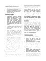
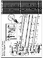
HTS700 HEDGE-TRIMMERS SAFETY & OPERATING INSTRUCTIONS READ THIS MANUAL CAREFULLY BEFORE OPERATING THE MACHINE WARNING: THIS SYMBOL INDICATES IMPORTANT SAFETY PRECAUTIONS TECHNICAL SPECIFICATIONS Name/Type HTS700 Net Weight kg Total Length mm Outward Total Width mm Size Total Height mm Type Blade Total Length mm 5.6 1055 252 240 Single sided 750 Automatic centrifugal clutch, spur gear, cam-crank 4.2 (63:15) Single cylinder air cooling 2-cycle gasoline engine 22.5 0.6 Mixture 25:1 (when using market oil)] 2-cycle engine oil Diaphragm, rotary valve IC-controlled fly wheel magnet RCJ6Y Recoil starter 109dB 7.2m/s2 Power Transmission Method Reduction Rate Type Displacement Volume cc Fuel Tank Capacity Fuel Used Engine Lubricating Oil Used Carburettor Sparking method Sparking Plug Starting Method Sound power level Vibration figures As part of our policy of continuous product improvement, we reserve the right to alter or amend this specification without notice. As a result, the product may differ from the information contained herein but any alteration will only be implemented without notice if it is classified as an improvement to the above specification. HEDGE-TRIMMER DESCRIPTION ① Left handle ② Recoil Starter ③ Fuel tank filler ④ Exhaust muffler ⑤ Gearbox clutch assembly ⑥ Right handle ⑦ Plate / deflector ⑧ Cutting blades ⑨ Throttle lever 10 Ignition Stop Switch 10 Fig.1. 1. 2. 3. Recoil Start Fuel Tank Cap Fuel Primer Bulb 1 2 3 Fig.2. SAFETY SYMBOLS 6. 1. 2. Warning, Danger, Caution Read the documentation Beware of objects being thrown from the operating zone. and 7. Warning: keep all people, animals and vulnerable objects at least 15 metres from the working area. 8. Directive 2000-14/CE. Guaranteed noise levels. 9. Danger: risk of intoxication. safety instructions which are provided in this user manual. 3. When operating this machine, use protective equipment such as goggles, helmet and ear defenders. 4. 5. Wear safety shoes and gloves. Beware: keep hands and feet away from moving parts. Always keep a safe distance from the cutting parts. 10. Danger: risk of fire or explosion. 11. Hot surface, risk of burn. GENERAL INFORMATION: SAFETY INSTRUCTIONS For your safety please read the owner’s manual and fully understand its contents before operating the hedge-trimmer. This two-stroke petrol powered hedge-trimmer is a precision cutting tool. For your own safety and the safety of others, read and be sure you understand all of the safety precautions outlined in the owner’s manual before attempting to operate the hedge trimmer. Retain the manual in a safe place in order to refresh your understanding of the safety instructions periodically. • Take care only to use the hedge-trimmer for the work it is intended, improper use can cause serious injury. Always adhere to information in the instruction manual. • Never allow children to operate the hedge-trimmer. Operators must be of sufficient strength, maturity and size to be able to lift the hedge-trimmer correctly for extended periods use. They must also be able to fully understand and follow instructions in this manual. • Exhaust fumes contain poisonous carbon monoxide gas. Only operate the hedge-trimmer out of doors in a well-ventilated area. Should you experience symptoms of headache and nausea associated with exhaust fumes, STOP the engine immediately. • When using the hedge-trimmer the operator is responsible for the safety of persons or objects that lie within the working area. • Two-stroke petrol is highly inflammable. Before refuelling always stop engine, do not smoke and make sure the area is well ventilated and free from any external flame or sparks. Wipe any fuel spilt immediately. Two-stroke petrol can burn or irritate skin. Change clothing immediately if fuel is spilt on it. Never remove fuel tank cap when the engine is running. • Always use thick safety gloves when operating the hedge-trimmer and never touch the blades when the engine is running as this will cause severe injury. • Never operate the hedge-trimmer under the influence of drugs, alcohol, or other medication that causes drowsiness. • Loose clothing or hair can lead to serious injury if caught in moving parts of the hedge-trimmer. Always where close fitting clothing. Always wear the appropriate protective clothing to avoid personal injury, including eye protection. goggles, or full specification safety glasses, safety helmet complete with ear protection, heavy-duty boots with non-slip soles and heavy-duty gloves. Before undertaking any work or maintenance, including refilling the fuel tank, STOP the engine and ensure blades come to a complete standstill. Take care to maintain your balance to avoid loss of control and injury. Always stand on firm even ground when operating the hedge-trimmer, never work from a ladder or any unsafe location. Keep both hands on the hedge-trimmer at all times and never attempt to cut overhead or with one hand. When operating the machine avoid prolonged exposure to vibration, SAFETY INSTRUCTIONS cont’d although the hedge-trimmer is designed to keep vibration to a minimum, it is recommended that short rest breaks are taken to minimise the harmful effect vibration may cause. HEDGE-TRIMMER Damaged or loose parts including blades can cause injury to the operator or bystanders. Always inspect the hedge-trimmer before using. Only use genuine approved spare parts for repair. Unauthorised use of non-genuine spare parts may invalidate warranty and could cause injury. Check the position and safety of all guards, handles, controls are free from defect.. Store hedge-trimmer in a safe, dry, cool area and away from direct sunlight. For prolonged periods of storage, drain fuel tank and run carburettor dry before storing your hedge-trimmer. Careful maintenance is essential for safety and optimum performance. Regularly check the hedge-trimmer adjustments and replace worn or damaged parts. If engine idle speed is set too high, cutting blades will not stop when the operator releases the throttle. To prevent injury, ensure idle speed is set correctly and blades do not turn when engine is idling. Replace or sharpen worn, dull or misadjusted cutting blades. FUEL MIXTURE: 25 : 1 Use fresh, unleaded petrol and mix synthetic two-stroke oil specially made for high performance two-stroke engines at a ratio of 25 parts petrol to 1 part of oil. Using synthetic oil will reduce the formation of ash and carbon deposits on the spark plug, piston, combustion chamber, muffler, as well as extending engine life and reducing harmful exhaust gasses. It is important to use only good quality fresh two-stroke mixture, which should be disregarded after four weeks. WARNING Two-stroke mixture gasoline is highly flammable and can explode under certain circumstances. Never overfill petrol tank so that fuel rises into the filler neck. Heat may cause fuel to expand and overflow through vents in the tank cap. After refuelling make sure petrol cap is securely closed. If two-stroke mixture is spilt on engine or tank, wipe clean immediately. ENGINE STARTING To start the engine proceed as follows:1. Ensure fuel tank is filled with correctly mixed fresh two-stroke mixture at a ratio of 25-1. 2. Switch ignition switch to on position. 3. Prime the carburettor by slowly pushing the priming button several times until fuel reaches the carburettor. 4. Push the choke lever to the closed position. 5. Squeeze throttle control trigger and depress orange throttle lock button. 6. With your left hand grip the throttle control handle and with your right hand firmly pull recoil starter four or five times, or until the engine starts. Fuel Filter 7. After starting release the choke lever to the open position (see Fig.2) 8. To avoid damage to recoil starter, do not pull recoil rope its entire length and do not let go of rope when it is fully extended, as this may cause injury and damage to the recoil mechanism. 9. Allow sufficient warm up time to maximise engine performance before load is applied. 10. Never touch the muffler, spark plug, or other metallic parts of engine while the engine is in operation, or immediately after shutting down the engine. Doing so may result in serious burns. Spark Plug Service Clean or replace spark plug and reset gap every 50 hours of operation. Never touch spark plug cap, or high tension voltage cable when engine is running to prevent severe electric shock. Cutting Blade Lubrication Service Before undertaking any maintenance to cutting blades, stop the engine and wait for the blades to come to a complete standstill. Disconnect spark plug cap from spark plug. Clean the surfaces of the blades and apply a light machine oil to prevent corrosion. STOPPING THE ENGINE By releasing throttle lever blades will come to a standstill (if engine idle is set too high, re-adjust throttle stop). Turn engine switch to off position. MAINTENANCE & ADJUSTMENTS Air Filter Service Clean air filter element every 20 hours. Unscrew air filter cover knob to remove air filter. Wash in warm soapy water, dry and lightly oil or replace with new. Never use hedge-trimmer with air filter element defective or missing as this will cause premature engine failure. Change fuel filter every 20 hours or annually. Gear Case Lubrication Lubricate gear case every 20 hours with high quality lithium high melting point gear case grease. STORAGE For prolonged periods of storage over 30 days drain all fuel mixture from tank and run the engine at idle speed until all fuel in the carburettor is used. Clean the engine and cutting blades. Remove spark plug and poor .5ml of new two-stroke oil through spark plug hole. Pull recoil starter slowly for several times with ignition switch in the off position. Replace spark plug. Store hedge-trimmer in a clean, dry place away from direct sunlight. CONDITIONS OF WARRANTY The manufacturer warrants the product against faulty materials and workmanship for a period of 2 years from the date of first purchase. The warranty is applicable when the product is used in normal “home owner” applications and by the original purchaser. If products are used for commercial or professional purposes, the warranty period is for 6 months from the date of first purchase. Warranty does not extend to failure due to fair wear and tear. The manufacturer undertakes to replace at his expense, any spare parts that are classified as defective by him or his appointed service dealer. The manufacturer will not accept liability for the replacement of the machine, either partially or wholly, and or consequential damages and or interest charges either directly or indirectly. Warranty does not cover failure due to: Insufficient maintenance Abnormal use or accidental damage Incorrect assembly, adjustment or operation of the product Spare parts that are subject to wear e.g. safety parts, belts, blades, blade supports, bearings, cables, guards, deflectors, spark plugs, air filters etc. Incorrect fuel mixture or fuel that is stale (over 4 weeks old). Neither does warranty extend to: Freight and packing costs. Use of non-genuine spare parts i.e. those from another manufacturer. Use of the machine for any other purpose than that for which it was designed. Use and maintenance of the machine in a manner not described in the owners manual. READ THE MANUAL CAREFULLY BEFORE OPERATING THE MACHINE When ordering spare parts please ensure that the correct model number and serial number of the product is registered. Retain the receipt of purchase without which no warranty can be offered. U.K. REPAIR AND MAINTENANCE To find your nearest stockist and authorised service dealer please contact: Mitox Garden Machinery Wincanton Business Park WINCANTON Somerset BA9 9RS U.K. Tel.: 01963 828050 Fax.: 01963 828052 37 38 The Parts List of Model 35 39 32 1E32FL Gasoline Engine 9 40 36 34 10 31 11 90 30 89 10 56 88 46 47 55 33 44A 12 45 58 57 59 43 41 34 44 85 18 19 28 5 52 64 61 62 65 53 25 66 26 51 80 25 24 77 51 74 68 49 70 91 PART NAME 48 71 67 PART NO. 53 72 65 75 54 23 73 76 NO. 50 24 31 78 7 22 63 34 83 82 81 8 20 21 27 86 87 4 6 17 29 84 1 3 14 16 60 79 2 13 15 42 QTY. NO. 1 1E34F.1.2 Screw 1 32 PART NO GB/T70.1 52 69 PART NAME Screw M5×25 50 QTY. NO. 2 PART NO. PART NAME QTY. 62 1E32FL-8 Gasket 1 2 1E34F.1-4 Outside Cover 1 33 1E32FL-4 Gasket 1 63 1E34F-3 Gasket 1 3 1E34F.1-1 Filter Net 1 34 GB9074.4 Screw M4×16 6 64 1E32FL.1 Muffler Ass'y 1 4 GB9074.4 Screw M5x55 5 GB845-ST4.2×12-F-H Screw 2 35 1E32FL-2 Guide Cover 1 65 GB96 Washer 5 5 1 36 GB845 Screw ST4.2×18-F 1 66 GB/T70.1 Screw M5×50 2 GB9074.3 Screw M5×16 3 1E34F.1.1 Inside Cover 1 37 1E34F.5-2 Cap 1 67 7 1E34F.1-3 Choke 1 38 1E40F-3A.8-2 Spring 1 68 1E32FL.6.1 Fuel Tank 1 8 1E34F.1-2 Choke Handle 1 39 1E34F.5-3 Plug Cap 1 69 1E32FL.6.2-1 Fuel Tank Lid 1 9 1E32FL.7 Carburetor 1 40 RCJ6Y Spark Plug 1 70 CG420.1.3.1-2 Gasket 1 6 10 1E34F-1 Gasket 2 41 Screw M5×10 1 71 EB-415.4.1.1-1 Inlet 1 11 1E32FL-1 Stand 1 42 1E32FL-9 Guide Cover 1 72 1E32FL.6.2-2 Inside Lid 1 73 1E32FL.6.2-3 Inside Lid GB9074.4 43 GB9074.4 Screw M5×30 4 13 1E34F.4 Admitting Pipe Ass'y 1 44 1E32FL.5.1 Fly Wheel 1 74 1E32FL.6.2-4 Chain 1 14 1E34F-2 Gasket 1 44A 1E32FL.5.2 Coil 1 75 1E34F.9.2-3 Cleaner Cover 1 15 1E32FL-5 Cylinder 1 45 1E32FL-6 Gasket 1 76 1E36FF.8.1-1 Plug 1 16 1E34F-9 Gasket 1 46 1E34F.5-1 Rubber Plug 1 77 1E34F.9.2-1 Fuel Pipe 1 17 1E32FL.3-1 Piston Ring 1 47 1E34F.5.1 Cord Comp. 1 78 1E34F.9.2-2 Fuel Pipe 1 18 1E32FL.3-2 Piston 1 48 GB6171 Nut M8×1 1 79 1E34F.11G Starter 1 19 1E34F.6-1 Washer 2 49 GB97.1 Washer 8 1 80 1E34F.11.1-1 Pipe 1 20 1E32FL.3-3 Piston Pin 1 50 1E34F-12 Screw Pin 2 81 1E34F.11-3 Rope 1 21 1E34F.6-4 Bearing 1 51 1E34F.10.1 Expander Ass'y 2 82 1E36F.1-1 Start Handle 1 22 1E34F.6-2 Ring 2 52 1E34F-13 Washer 2 83 1E36F.1-5 Chain 1 23 1E32FL.4-1 Crank Case 1 53 1E34F-11 Washer 2 84 1E34F.11G.1 Start Cover Ass'y 1 24 1E36F.2 Seal 2 54 1E34F.10-1 Spring 1 85 1E34F.11-2 Start Rope Reel 1 Bearing 6001/P5 2 55 1E32FL-10 Rubber Plug 1 86 1E34F.11-1 Recoil Spring 1 1 12 25 GB9074.4 GB/T 276 Screw M5×20 2 1 26 1E32FL.3.1 Crank Shaft 1 56 1E32FL-7 Guide Cover 1 87 GB9074.6 Screw M5×10 27 1E40FP-3Z.3-1 Key 1 57 GB9074.4 Screw M5×20 4 88 1E32FL.2 Start Reel Gasket 1 58 GB9074.4 Screw M4×20 2 89 1E34F.8-1 Start Claw 1 2 59 1E40F-3A.9 Clip Start Spring 1 Fuel Tank Lid Ass'y 1 28 1E34F.7-2 29 GB/T119.2 Pin 3×10 1 90 1E34F.8-2 30 GB848 Washer 5 2 60 1E32FL.4-2 Crank Case 1 91 1E32FL.6.2 31 GB93 Washer 5 4 61 1E32FL-3 Stand 1 1