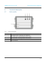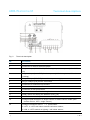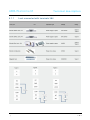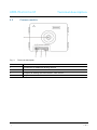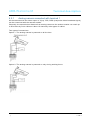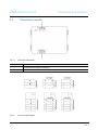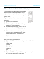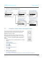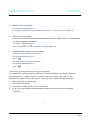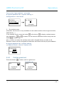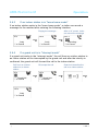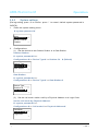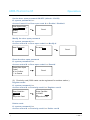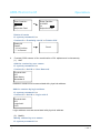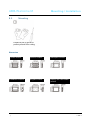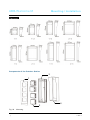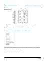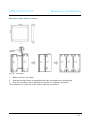
1
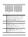
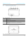
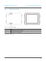
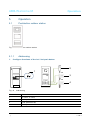
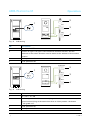
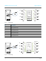
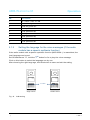
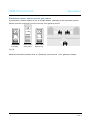
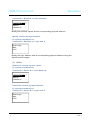
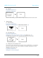
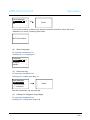
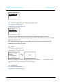
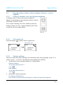
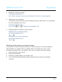
VER:1.0 │
│ 04.04.2014
ABB-Welcome M
Pos: 2 /DinA4 - Anl eitun gen Online /Inh alt/KNX/Doo rEntry /832 20-AP- xxx/Tit elblat t - 832 20-AP-xxx - ABB @ 1 9\m od_ 132 3249 806 476 _15. docx @ 11 108 4 @ @ 1
M25102xC
M25102xA-xM25102xPx.
M25102xK-x.
M25102xCR.
5102xDN
Outdoor station
=== E nde der Liste für Tex tma rke C over == =
ABB-Welcome
Pos: 4 /Busc h-Ja ege r (N eust rukt ur)/ Mo dul-St ruktu r/Onli ne-D oku ment ation /Inh altsve rzeich nis ( --> Fü r alle Doku men te <-- )/In haltsve rzeic hnis @ 19\ mod _13 206 490 4438 6_1 5.d ocx @ 109 653 @ @ 1
1
2
3
4
5
6
7
8
Safety ....................................................................................................... 3
Intended use ............................................................................................. 3
Environment.............................................................................................. 3
3.1
ABB devices ............................................................................. 3
Terminal description .................................................................................. 5
4.1
Audio module ............................................................................ 5
4.1.1
Lock connected with terminals 3&4 ............................................ 8
4.2
Camera module ........................................................................ 9
4.2.1
Analog camera connected with terminal 1 ................................ 10
4.2.2
Detached camera connection .................................................. 11
4.3
Push button module ................................................................ 12
4.4
Keypad module ....................................................................... 13
4.5
Display and card reader module .............................................. 15
4.6
Nameplate module .................................................................. 17
Operation................................................................................................ 18
5.1
Pushbutton outdoor station ...................................................... 18
5.1.1
Addressing.............................................................................. 18
5.1.2
Setting the language for the voice messages ........................... 22
5.2
Pushbutton Outdoor Station with display module ...................... 24
5.3
Pushbutton Outdoor Station with keypad module ..................... 25
5.4
Keypad outdoor station............................................................ 27
5.4.1
Call a resident (3 types)........................................................... 27
5.4.2
Call the guard unit ................................................................... 28
5.4.3
If an indoor station is in "leave home mode" ............................. 29
5.4.4
If a guard unit is in "intercept mode" ......................................... 29
5.4.5
System settings....................................................................... 30
5.5
Keypad outdoor station without display .................................... 39
5.5.1
Calling a resident, just input physical address .......................... 39
5.5.2
Call guard unit......................................................................... 39
5.5.3
System settings....................................................................... 39
Advanced configuration ........................................................................... 41
Technical data......................................................................................... 42
Mounting / Installation.............................................................................. 43
8.1
Requirements for the electrician............................................... 43
8.2
General installation instructions ............................................... 44
8.3
Mounting................................................................................. 45
=== E nde der Liste für Tex tma rke TOC == =
|
—2—
ABB-Welcome M
Safety
Pos: 6 /Busc h-Ja ege r (N eust rukt ur)/ Mo dul-St ruktu r/Onli ne-D oku ment ation /Übe rschri ften (- -> Für alle D okum ent e < --)/ 1. Eb ene/S - T /Sicher heit @ 18\ mod _13 026 127 917 90_ 15.d ocx @ 103 357 @ 1 @ 1
1
Safety
Pos: 7 /Busc h-Ja ege r (N eust rukt ur)/ Mo dul-St ruktu r/Onli ne-D oku ment ation /Sicher heit (-- > Für alle Dok um ente <- -)/Wa rn hinweise /Sicher heit - 23 0 V @ 18\m od_ 130 260 681 675 0_15 .docx @ 1 033 08 @ @ 1
Warning
Electric voltage!
Risk of death and fire due to electrical voltage of 100-240 V.
–
W ork on the 100-240V supply system may only be performed by
–
Disconnect the mains power supply prior to installation and/or
authorised electricians!
disassembly!
Pos: 8 /Busc h-Ja ege r (N eust rukt ur)/ Mo dul-St ruktu r/Onli ne-D oku ment ation /Übe rschri ften (- -> Für alle D okum ent e < --)/ 1. Eb ene/A - F /Bestim mun gsge mä ßer Geb rau ch @ 18\ mod _13 027 6332 131 6_1 5.do cx @ 1034 83 @ 1 @ 1
2
Intended use
Pos: 9 /DinA4 - Anl eitun gen Online /Inh alt/KNX/Doo rEntry /832 20-AP- xxx/Besti mmu ngsg em aesse r Ge bra uch - 83 220 -AP-xxx- 500 @ 2 0\mo d_1 324 561 168 699 _15. docx @ 11 272 8 @ @ 1
The outdoor station is an integral part of the ABB W elcome door communication system
and operates exclusively with components from this system. The device must only be
used with suitable ABB flush-mounted installation sockets and rain hood.
Pos: 10 /B usch-J aeg er (Neus truk tur )/M odul -Strukt ur/O nline -Doku me ntatio n/Übe rsch rifte n ( --> Fü r alle Doku men te < -- )/1. E bene /U - Z/U mwelt @ 18\ mod _13 026 141 5896 7_1 5.d ocx @ 103 383 @ 1 @ 1
3
Environment
Pos: 11 /B usch-J aeg er (Neus truk tur )/M odul -Strukt ur/O nline -Doku me ntatio n/Umw elt ( --> F ür all e Doku me nte <-- )/Hinweis e/Hinw eis - U mwelt - Hinweis Elektr oge räte @ 1 8\mo d_1 302 763 973 434 _15. docx @ 10 350 0 @ @ 1
Consider the protection of the environment!
Used electric and electronic devices must not be disposed of with
domestic waste.
–
The device contains valuable raw materials which can be recycled.
Therefore, dispose of the device at the appropriate collecting
depot.
Pos: 12 /Di nA4 - A nleitu ngen Onlin e/Ueb ersc hrift en/2 ./ABB Gera ete @ 19 \mo d_1 323 162 843 832_ 15. docx @ 11 087 5 @ 2 @ 1
3.1
ABB devices
Pos: 13 /B usch-J aeg er (Neus truk tur )/M odul -Strukt ur/O nline -Doku me ntatio n/Umw elt ( --> F ür all e Doku me nte <-- )/Hinweis e/Hinw eis - U mwelt - ABB Elektro ger äte @ 19\ mo d_1 3231 627 458 39_ 15.d ocx @ 110 867 @ @ 1
All packaging materials and devices from ABB bear the markings and test seals for
proper disposal. Always dispose of the packing materials and electric devices and their
components via the authorized collection depots and disposal companies.
|
—3—
ABB-Welcome M
Environment
ABB products meet the legal requirements, in particular the laws governing electronic
and electrical devices and the REACH ordinance.
(EU-Directive 2002/96/EG W EEE and 2002/95/EG RoHS)
(EU-REACH ordinance and law for the implementation of the ordinance (EG)
No.1907/2006)
|
—4—
ABB-Welcome M
4
Terminal description
4.1
Audio module
Fig. 1
Terminal description
Terminal description
No.
Function
1
LED flashes slowly, indicating a call established
LED flashes fast, indicating that the system is busy
2
LED illuminates, indicating possible communication.
3
LED illuminates, indicating the door is unlocked
4
Call pushbuttons
|
—5—
ABB-Welcome M
Fig. 2
Terminal description
Terminal description
No.
Functions
1
Connector for camera module
2
Connector for device software update
3
Plug-in clamps (COM-NC-NO) for floating output, door opener (30VAC/DC
1A)
4
Plug-in clamps (Lock-GND) for door opener (18V 4A impulsive, 250 mA
holding)
5
Plug-in clamps (DC-GND) for additional power supply
6
Plug-in clamps (a-b) for Bus connection
7
Connector for induction loop module
8
Connector for next module
9
Connector for exit push button
10
Connector for sensor for checking the door status
11
Rotary switch for setting the address of OS (1-9)
12
Set feedback tones for push buttons: ON/OFF
13
Configure push buttons in a single column or double column mode (ON=
14
Configure functions of the 1 st / 2nd push button.
double column; OFF= single column)
3->OFF, 4->OFF=call indoor station/call indoor station;
3->ON, 4->OFF=switch on lighting / call indoor station;
|
—6—
ABB-Welcome M
Terminal description
3->OFF, 4->ON=call guard unit / call indoor station;
3->ON, 4->ON=switch on lighting / call guard unit.
15
Adjust the loudspeaker volume.
16
Adjust the door lock release time, 1-10s (available for the
lock connected with the Lock-GND)
|
—7—
ABB-Welcome M
4.1.1
|
Terminal description
Lock connected with terminals 3&4
—8—
ABB-Welcome M
4.2
Fig. 3
Terminal description
Camera module
Terminal description
No.
Functions
1
Connector for additional analog camera
2
Connector for audio module
3
Jumper for setting the video format: PAL /NTSC
4
Adjust the camera view area
|
—9—
ABB-Welcome M
4.2.1
Terminal description
Analog camera connected with terminal 1
All the cameras with the video output of 1Vp-p 75Ω ,CVBS (composite video broadcast signal)
can be connected with the camera module.
Generally, the transmission distance from analog cam era to the outdoor station can reach up
to 50 meters by Coax cables or about 10 m eters by other types of cables.
Two types of connections:
Option 1: The analog cam era is powered on all the time
Option 2: The analog cam era is powered on only during working hours
|
— 10 —
ABB-Welcome M
4.2.2
Terminal description
Detached camera connection
Cam era m odule can be used as a detached camera, and the wiring is shown in below.
3 pairs 2-wire
bus together
Max:10 metres
|
— 11 —
ABB-Welcome M
4.3
Fig. 4
Push button module
Terminal description
No.
Functions
1
Connector for previous module
2
Connector for next module
Fig. 5
|
Terminal description
Terminal description
— 12 —
ABB-Welcome M
Terminal description
No.
Functions
1
Regardless of the structure of the push button module, the button numbers
are listed from the top to bottom and from left to right (in the double column
mode)
2
Lighting switch / call guard unit function is always assigned to the 1 st /2nd
button.
3
User names can be printed by the labelling tool of the W elcome M
configuration software.
4.4
Fig. 6
Keypad module
Terminal description
No.
Functions
1
Program button
2
Connector for previous module
3
Connector for device software update
4
USB connector for the connection to the PC : download/upload the
configuration
5
|
Connector for next module
— 13 —
ABB-Welcome M
Terminal description
Pic 1
Fig. 7
Pic 2
Terminal description
No.
Functions
1
Call resident
A visitor inputs an indoor station number (001) or apartment number (e.g.
0101, programmed in advance) to call a resident.
*Also, the visitor can select a resident name with the button
button
or the
of the accompanying display module to make a call.
Meanwhile, pressing the button
can cancel the call.
*This function is only available in Pic1.
2
Calling the guard unit
A visitor can call a guard unit by pressing the button
if the guard unit is
available in the system.
3
Unlocking by password
Press"
+ password+
“to release the lock connected with terminals
"LOCK-GND” of the audio module.
Press "
+2 +
+ password +
" to release the 2nd-lock connected
with terminals "COM-NC-NO" of the audio module.
The initial password is 123456 and residents can set their own customized
password with indoor stations.
4
System engineering configuration
Press "
+
+ system password +
" to enter the system
engineering configuration menu.
The initial system password is 345678 and it can be modified by the
administrator.
|
— 14 —
ABB-Welcome M
4.5
Fig. 8
Terminal description
Display and card reader module
Terminal description
No.
Functions
1
Program button
2
Connector for previous module
3
Connector for device software update
4
Connector for W iegand output
5
USB connector for connecting to the PC: download/upload the
configuration
6
Fig. 9
|
Connector for the next module
Terminal description
— 15 —
ABB-Welcome M
No.
Functions
1
LCD display
2
Support ID or IC card.
Terminal description
Swipe the registered card to release the door lock. The card can be
programmed through the module itself, or using a PC to download the
program file. (M251021CR is accompanied with an ID card reader, while
the M251022CR is accompanied with an IC card reader.)
3
Support Wiegand output.
The default Wiegand format is 26 bits but it can also be extended to 34
bits.
*The display m odule must be connected after audio module.
Technical Specification:
M251021CR:Display module with ID card reader
W ork
Frequency
Standard
Support
card
Output
format
125KHz
ISO18000-2
EM4100, EM4205, EM4305, EM4450, TK4100, T5567 / T5577 Compatible
HID 2
Wiegand 26, 34bit
M251022CR:Display module with IC card reader
W ork
Frequency
Standard
Support
card
Output
format
|
13.56MHz
ISO 14443A
Mifare One S50/S70,etc.
Wiegand 26, 34bit
— 16 —
ABB-Welcome M
4.6
Fig. 10
Terminal description
Nameplate module
Terminal description
No.
Functions
1
Connector for previous module
2
Connector for next module
Labeling of the nam eplate m odule can be printed by the labelling tool of the W elcome M
configuration software.
Pos: 18 /Di nA4 - A nleitu ngen Onlin e/Ueb ersc hrift en/1 ./Bedie nun g @ 18\m od_ 130 261 392 416 5_15 .docx @ 1 033 65 @ 1 @ 1
|
— 17 —
ABB-Welcome M
5
Operation
Operation
Pos: 19 /Di nA4 - A nleitu ngen Onlin e/Ueb ersc hrift en/2 ./Nor male r Bet rieb @ 18 \mo d_1 302 768 8209 65_ 15. docx @ 10 3540 @ 2 @ 1
5.1
Pushbutton outdoor station
Fig. 11
Pushbutton outdoor station
Pos: 20 /Di nA4 - A nleitu ngen Onlin e/Ueb ersc hrift en/3 ./Bedie nele men te @ 20\ mod _13 232 6022 055 9_1 5.do cx @ 1 116 47 @ 3 @ 1
5.1.1
1.
Addressing
Configure functions of the 1st / 2nd push button
001
2
1
002
DIP
3
3 4
003
1
2
3
Fig. 12
Addressing
No.
Functions
1
3->OFF, 4->OFF
2
Call apartment 01
3
Call apartment 02
4
Call apartment 03
|
4
— 18 —
ABB-Welcome M
Operation
2
1
001
DIP
3
3 4
002
4
1
2
Fig. 13
Addressing
No.
Functions
1
3-> ON, 4->OFF
2
Switch on light. The light is connected with a switch actuator, and the
address of the switch actuator must be same as the address of this outdoor
station.
3
Call apartment 01
4
Call apartment 02
Guard unit
2
1
001
DIP
3
3 4
002
1
2
Fig. 14
4
Addressing
No.
Functions
1
3-> OFF, 4-> ON
2
Call the guard unit. If there are multiple guard units in the same section, all
guard units will ring at the same time when a visitor presses the button
“call guard unit”.
3
Call apartment 01
4
Call apartment 02
|
— 19 —
ABB-Welcome M
Operation
2
1
Guard unit
DIP
3
3 4
001
4
1
Fig. 15
Addressing
No.
Functions
1
3-> ON, 4-> ON
2
Switch on lights
3
Call guard unit
4
Call apartment 01
2.
Configure push button in a single column or double column modes
001
2
002
1
3
ON
003
2
4
1
2
3
4
Fig. 16
5
Addressing
No.
Functions
1
2-> OFF
2
Call apartment 01
3
Call apartment 02
4
Call apartment 03
5
Call apartment 04
|
004
— 20 —
ABB-Welcome M
Operation
001
002
2
001
1
ON
3
003
004
005
006
4
2
5
6
7
1
3
5
7
007
8
Fig. 17
2
4
6
8
008
9
Addressing
No.
Functions
1
2-> ON
2
Call apartment 01
3
Call apartment 02
4
Call apartment 03
5
Call apartment 04
6
Call apartment 05
7
Call apartment 06
8
Call apartment 07
9
Call apartment 08
Guard unit
2
1
ON
DIP
3
001
002
4
5
003
2 3 4
6
7
005
8
Fig. 18
|
004
1
3
5
2
4
6
006
9
Addressing
— 21 —
ABB-Welcome M
Operation
No.
Functions
1
2-> ON,3-> ON, 4-> ON
2
Switch on lights
3
Call the guard unit
4
Call apartment 01
5
Call apartment 02
6
Call apartment 03
7
Call apartment 04
8
Call apartment 05
9
Call apartment 06
5.1.2
Setting the language for the voice messages (if the audio
module has a speech synthesis function)
If the audio module with a speech synthesis function (M251024A-.) is assembled, the
local language can be set.
Set OS address as "0", hold the
1st button for 3s to play the voice message.
Click on this button to select the language one by one.
After choosing the right language, hold this button to save and exit the setting.
1
2
3
4
Single column
Fig. 19
|
1st button
1
3
5
7
2
4
6
8
Double column
Addressing
— 22 —
ABB-Welcome M
Operation
Pushbutton outdoor station used as gate station
If pushbutton outdoor station is set as a gate station, gateway as an important system
device must be used and it must be set as floor gateway mode.
Apartment 01 A
Apartment 02 B
Apartment 03 C
Apartment 01 A
Apartment 04 D
Apartment 04 A
Apartment 02 B
Apartment 05 E
Apartment 06 F
Apartment 05 B
Apartment 03 C
Outdoor station
Left building
Outdoor station
Gate entrance
Apartment 06 C
Outdoor station
Right building
Fig. 20
Detailed information please refer to “Gateway “user manual,floor gateway chapter.
Pos: 71 /Di nA4 - A nleitu ngen Onlin e/Ueb ersc hrift en/3 ./Abschl usswide rsta nd @ 19\ mod _13 219 5807 990 6_1 5.do cx @ 1100 83 @ 3 @ 1
Pos: 72 /Di nA4 - A nleitu ngen Onlin e/In halt/KNX/Do orEnt ry/Bedie nun g/Abschl usswide rsta nd s etzen 83 220 -AP-xxx @ 19\ mod _13 1072 339 236 9_1 5.do cx @ 1 078 41 @ @ 1
|
— 23 —
ABB-Welcome M
5.2
Operation
Pushbutton Outdoor Station with display module
The Display and card reader module can be assembled
with a push button outdoor station and the user can
swipe cards to open the door. For such combination, a
master card is needed for an electrician to manage this
outdoor station.
Register a master card/deactivate master card (we
recommend that this work is carried out by specialized
personnel):
1.
Disconnect the power supply.
2.
Reconnect the power
3.
Hold the “program button” for 5s to enter "program
4.
Any card swiped by the reader during this time will
Fig. 21
master card" interface within 30s.
be taken to be the new MASTER card. A prompt
“Register master card successfully" will appear on
the screen.
5.
If the card exists, when you swipe it again, the
information will be deleted, and a prompt “Delete
master card successfully" will appear on the
screen.
Only 1 master card can be registered.
Enter system setting using master card:
1.
2.
Swipe the MASTER card to enter the setting menu. Three LEDs will turn on.
6 options:
Program Card;
Language;
Wiegand Output;
Choose Door
Date & Time;
Back
There is a 5s countdown for each option.
3.
Swipe the MASTER card again within 5s to change to the next option.
Or, 5s over, the current option will be chosen.
|
— 24 —
ABB-Welcome M
4.
Operation
30s Over, to exit the settings menu.
Swipe the MASTER
card
Menu_________05
Program Card--- ∧
Language
Wiegand Output ∨
5s over, choose current
option
==> ==>
Menu_________√
Program Card--- ∧
Language
Wiegand Output ∨
Swipe the MASTER
card, enter the setting
==>
Swipe the MASTER
Card within 5s to move
to next option.
Swipe the MASTER
Card within 5s to
move to next option.
==>
5.3
Menu_________05
Program Card ∧
Language-------Wiegand Output ∨
Proximity Card 05
Register Card--- ∧
Delete Card
Delete All
∨
==>
Menu_________05
Program Card ∧
Language
Wiegand Output ∨
Pushbutton Outdoor Station with keypad module
The keypad module can be assembled with a push
button outdoor station, and users can enter the
password to open the door.
Users can enter the system settings menu by the
following steps (during setting, press “#” to confirm,
press “*” to cancel, the default system password is
345678):
1.
Set the device as an Outdoor Station or a Gate
Station.
Outdoor Station:
Fig. 22
#* system password # =>
1 # => 1 #
Gate Station:
#* system password # =>
1 # => 2 #
2.
Modify "system password"
#* system password # =>
2 # => Enter new password (6-8 bits) # => Enter the password again #
|
— 25 —
ABB-Welcome M
3.
Operation
Modify "door open code"
#* system password # =>
3# => Enter new door open code (6-8 bits) # => Enter the code again #
4.
Set the voice message
If the audio module with the speech synthesis function (M251024A-.) is assembled,
the local language can be set.
#* system password # =>
4# => Press
5.
or
to choose the language => #
Enable/disable access control function
Enable access control function:
#* system password # =>
5# => 1 #
Disable access control function:
#* system password # =>
5# => 2 #
*Reset the system password of keypad module:
It is possible to reset the system password to factory-setting if you have forgotten it.
The restoration of default factory settings does not delete the rest of the
information programmed on the system, such as user names and other settings.
1.
Disconnect the power supply.
2.
Reconnect the power
3.
Hold the “program button” for 5s within 30s.
4.
A “di” will be sounded and the system password will be reset to the default
(345678).
|
— 26 —
ABB-Welcome M
5.4
5.4.1
1.
Operation
Keypad outdoor station
Call a resident (3 types)
By physical address
Physical address is the internal code which the outdoor
station will send through the bus connection to indoor
stations or other devices in the system. For each
apartment, physical address means the address of an
indoor station which is installed in the apartment. For
each building, physical address means the address of a
gateway which is installed for each building, and it is
also called the building number.
In standby mode, a visitor can press the physical
Fig. 23
address corresponding to the residence that you want to
call directly, from 001 to 250.
For a complex building, a visitor needs to press the
building number (01~60) + physical address (001~250)
or make a call in the gate station.
Enter Physical A
dd.:
01 001
2.
By logic address
Logic address is a code that a visitor can press to make a call. The code must be
assigned first and then associated with the physical address.
The apartment No. or some special codes can be used to set the logic address, which is
easy for the users to remember.
Set the logic address by taking the following steps:
Assign the logic address:
#* system password # => system setting =>
Address Book => Add => Logic Add
Physical Add.:
001
Logic Add.:
0101
|
— 27 —
ABB-Welcome M
Operation
Turn on the “logic address” call mode
#* system password # => system setting =>
Configuration => Call mode
Call Mode_______
Physical Add. ∧
Logic Add.-------∨
3.
==>
No. Of digit:
-4(1-8 Digits)
By resident name
(Remarks: this function is only available for the outdoor station with a keypad module
(M251021K-.).)
In the standby mode, press the button
Use the buttons
button
and
or the button
to display resident names.
to search for the desired residential station and press the
to make a call.
Also, a visitor can enter the resident name with a keypad directly to make a call.
Resident names must be assigned first and then associated with the physical address.
#* system password # => system setting
=> Address Book => Add => Contact List
Physical Add.:
01001
User Name:
Federico
5.4.2
Call the guard unit
Press the button
to make a call to a guard unit.
Accept the call
30 s
120 s
==>
Guard Unit
“*“ to Cancel
|
Guard Unit
“*“ to Cancel
— 28 —
ABB-Welcome M
5.4.3
Operation
If an indoor station is in "leave home mode"
If an indoor station works in the “leave home mode”, a visitor can record a
message for the resident after entering the following interface.
Playing the message...
30 s
120 s
==>
Andy
“*“ to Cancel
5.4.4
After a “di” sound, visitor
can record the message
001 s
==>
Andy
“*“ to Cancel
Recording...
“*“ to Cancel
If a guard unit is in "intercept mode"
If a guard unit works in the “intercept mode”, the call from an outdoor station to
an indoor station will be intercepted by the guard unit and after the identity is
confirmed, the guard unit will forward the call to the indoor station.
Call from an outdoor
station to an indoor
station
30 s
120 s
==>
Guard Unit
“*“ to Cancel
Guard unit transfers the
call to an indoor station
GU accept the call
==>
==>
Guard Unit
“*“ to Cancel
120 s
Andy
“*“ to Cancel
|
— 29 —
ABB-Welcome M
5.4.5
Operation
System settings
(During setting, press “#” to confirm, press “*” to cancel, default system password is
345678):
1.
Enter the system setting menu
#* system password #
Menu__________
Configurations-- ∧
Access Control
Contact
∨
2.
Configurations
(1)
Set the device as an Outdoor Station or a Gate Station.
Outdoor Station:
#* system password # =>
Configurations # => Device Type # => Outdoor St.
# (Default)
Device Type_____
Outdoor St. ● -- ∧
Gate Station
∨
Gate Station:
#* system password # =>
Configurations # => Device Type # => Gate Station #
Device Type_____
Outdoor St.
∧
Gate Station ●∨
(2)
Set the call mode: make a call by a Physical Address or a Logic Code
Set the call mode by Physical Address:
#* system password # =>
Configurations # => Call mode # => Physical Address #
Call Mode_______
Physical Add.● ∧
Logic Add.:
∨
|
— 30 —
ABB-Welcome M
Operation
Set the call mode by a Logic Code,No. of digits (1-8 digits):
#* system password # =>
Configurations # => Call mode # => Logic Code #
Call Mode_______
Physical Add. ∧
Logic Add.: ●∨
(3)
System password setting
Modify the system password
#* system password # =>
Configurations # => System code # => Modify #
New Password:
******
==>
Re-enter:
******
==>
Done!
Reset the system password
#* system password # =>
Configurations # => System code # => Reset #
Reset System
Code?
“#“ to Confirm
“*“ to Cancel
3.
==>
Done!
Access control
(1)
Door open code
The password can be set as 6-8 digits. The default door open password is
"123456”, and it can be changed with an outdoor station.
Meanwhile, users can set their own passwords with indoor stations, totally, 6000
passwords can be stored.
|
— 31 —
ABB-Welcome M
Operation
Set the door open password ON/OFF (default: 123456)
#* system password # =>
Access Control # => Door open code # => Enable / Disable #
Door Open Code__
Disable
-- ∧
Modify
Reset
∨
==>
Done!
Modify the door open password
#* system password # =>
Access control # => Door open code # => Modify #
New Password:
******
==>
Re-enter:
******
==>
Done!
Reset the door open password
#* system password # =>
Access control # => Door open code # => Reset #
Reset Door Open
Code?
“#“ to Confirm
“*“ to Cancel
(2)
==>
Done!
Proximity card (3000 cards can be registered for outdoor station.)
Register cards:
#* system password # =>
Access control # => Proximity card # => Register card #
Enter Card No.:
0123456
Or
Swipe the Card
==>
Enter Card No.:
0123456
Or
Done!
Swipe the Card
Delete cards:
#* system password # =>
Access control # => Proximity card # => Delete card #
|
— 32 —
ABB-Welcome M
Enter Card No.:
0123456
Or
Swipe the Card
==>
Operation
Enter Card No.:
0123456
Or
Done!
Swipe the Card
Delete all cards
#* system password # =>
Contact # => Proximity card # => Delete All #
Delete All
Cards?
“#“ to Confirm
“*“ to Cancel
4.
==>
Done!
Contact(3,000 names of the combination of 24 alphanumeric characters)
(1)
Add
Add the contact by user names
#* system password # =>
Contact # => Add # => User Names #
Physical Add.:
001
User Name:
Alexander.G
Resident names must be associated with physical address.
Add the contact by logic address
#* system password # =>
Contact # => Add # => Logic add. #
Physical Add.:
001
Logic Add.:
0101
Logic address must be associated with physical address.
(2)
Modify
Modify contact by user names
#* system password # =>
|
— 33 —
ABB-Welcome M
Operation
Contact # => Modify # => User Names #
_______________
Alexander.G -- ∧
Bodin.K
Christian.G
∨
Modify the resident names and its corresponding physical address.
Modify contact by logic address
#* system password # =>
Contact # => Modify # => Logic add. #
Enter Logic
Add.:
0101
Modify the logic address and its corresponding physical address using the
alphanumeric keypad.
(3)
Delete
Delete the contact by user names
#* system password # =>
Contact # => Delete # => User Names #
_______________
Alexander.G -- ∧
Bodin.K
Christian.G
∨
Delete the contact by logic address
#* system password # =>
Contact # => Delete # => Logic add. #
Enter Logic
Add.:
0101
|
— 34 —
ABB-Welcome M
(4)
Operation
Clear all
#* system password # =>
Contact # => Clear all #
Delete All Names?
“#“ to Confirm
“*“ to Cancel
==>
Done!
Clear all lists including resident names and logic address entries from this menu.
5.
System setting
(1)
Date and time
#* system password # =>
Settings # => Date & time # => Enter time and date => #
2013-01-01
07:00
==>
Done!
“#” to Confirm
(2)
Door Open Time
#* system password # =>
Settings # => Door Open Time # => Time 1-10s (default: 3s) => #
Lock(NC-NO-C) means the lock connected with COM-NC-NO terminals.
Lock(NC-NO-C)
Open
Time (1-10s)
3s
“#” to Confirm
==>
Done!
(3) Setting the voice message on/off
If the audio module with the speech synthesis function (M251024A-.) is assembled,
the speech synthesis function can be enabled or disabled. Meanwhile, the local
language can be chosen, too.
#* system password # =>
Settings # => Voice message #
|
— 35 —
ABB-Welcome M
Voice Message___
On
● -- ∧
Off
∨
==>
Operation
Done!
If the audio module is without the speech synthesis function, there will be an
indication for users if entering this menu.
No This Function!
(4) Select language
#* system password # =>
Settings # => Language #
Language_______
English
● -- ∧
Français
Italiano
∨
(5)
W elcome msg.
#* system password # =>
Settings # => Welcome Msg. #
New Message:
ABB Welcome!
“#“ to Confirm
“*“ to Cancel
==>
Done!
Max 64 characters can be entered.
(6)
Setting the W iegand output digits
#* system password # =>
Settings # => Wiegand Output #
|
— 36 —
ABB-Welcome M
Operation
Wiegand Output__
26 bit !
● -- ∧
34 bit !
∨
(7)
Set the related door lock when swiping the card
#* system password # =>
Settings # =>Choose Door #
Door Select______
1st(LOCK-GND)●∧
2nd(NC-CO-COM)
∨
Setting the lock which will be released when swiping the registered card:
1st (LOCK-GND): the lock connected with the LOCK-GND terminals will be released
when swiping the card.
2ND (NC-NO-COM): the lock connected with the NC-NO-COM terminals will be
released when swiping the card.
(8) Reset
#* system password # =>
Settings # => Reset # => #
Reset to Factory
Default?
“#“ to Confirm
“*“ to Cancel
==>
Done!
Reset all settings to factory settings, but other information, e.g. user names, logic
addresses and cards information cannot be reset.
(9)
Information
#* system password # =>
Settings # => Information #
|
— 37 —
ABB-Welcome M
Operation
Audio module: ∧
V1.07_131106
Card reader:
V0.10_131107 ∨
View the software information of each modules of the outdoor station.
*Reset the system password of keypad module:
It is possible to reset the system password to factory-setting if you have forgotten it.
The restoration of default factory settings does not delete the rest of the
information programmed on the system, such as user names and other settings.
1.
Disconnect the power supply.
2.
Reconnect the power
3.
Hold the “program button” for 5s within 30s.
4.
A “di” will be sounded and the system password will be reset to the default
(345678).
Pos: 67 /Di nA4 - A nleitu ngen Onlin e/Ueb ersc hrift en/2 ./Reini gung @ 1 9\m od_ 131 0733 980 533 _15. docx @ 10 785 3 @ 2 @ 1
|
— 38 —
ABB-Welcome M
5.5
5.5.1
Operation
Keypad outdoor station without display (Camera + audio+
keypad)
Calling a resident, just input physical address
In standby mode, a visitor can press the physical
address corresponding to the residence that you want to
call directly, from 001 to 250.
For a complex building, the visitor needs to press the
building number (01~60) + physical address (001~250)
to make a call from a gate station.
Fig. 24
5.5.2
Call guard unit
Press the button
to make a call to a guard unit.
Accept the call
30 s
120 s
==>
Guard Unit
“*“ to Cancel
5.5.3
Guard Unit
“*“ to Cancel
System settings
Users can enter the system settings by the following steps (during settings, press “#” to
confirm, press “*” to cancel. The default system password is 345678.):
1.
Set the device as an Outdoor Station or a Gate Station.
Outdoor Station:
#* system password # =>
1 # => 1 #
Gate Station:
#* system password # =>
1 # => 2 #
2.
Modify the "system password"
#* system password # =>
2 # => Enter new password (6-8 bits) # => Enter the password again #
|
— 39 —
ABB-Welcome M
3.
Operation
Modify the "door open code"
#* system password # =>
3# => Enter new door open code (6-8 bits) # => Enter the code again #
4.
Setting the voice message
If the audio module with the speech synthesis function (M251024A-.) is assembled,
the local language can be set.
#* system password # =>
4# => Press
5.
or
to choose the language => #
Enable/disable the access control function
Enable access control function:
#* system password # =>
5# => 1 #
Disable access control function:
#* system password # =>
5# => 2 #
*Reset the system password of keypad module:
It is possible to reset the system password to factory-setting if you have forgotten it.
The restoration of default factory settings does not delete the rest of the
information programmed on the system, such as user names and other settings.
1.
Disconnect the power supply.
2.
Reconnect the power
3.
Hold the “program button” for 5s within 30s.
4.
A “di” will be sounded and the system password will be reset to the default
(345678).
Pos: 21 /Di nA4 - A nleitu ngen Onlin e/In halt/KNX/Do orEnt ry/83 220 -AP-xxx/Be dienel eme nte - 8 322 0-AP-xxx @ 18\ mo d_1 3032 128 536 05_ 15.d ocx @ 103 673 @ @ 1
2149 @ @ 1
|
— 40 —
ABB-Welcome M
Advanced
configuration
Pos: 70 /Di nA4 - A nleitu ngen Onlin e/Ueb ersc hrift en/2 ./Ge raet eeins tellun gen @ 1 8\mo d_1 302 768 847 744 _15. docx @ 10 354 8 @ 2 @ 1
6
Advanced configuration
Connect to the PC to configure the keypad or display
Fig. 25
Pos: 75 /B usch-J aeg er (Neus truk tur )/M odul -Strukt ur/O nline -Doku me ntatio n/Steu er mod ule - Onlin e-Dok ume ntati on ( -- > F ür alle Dok ume nte <- -)/ +++ ++ ++ +++ ++ S eiten umb ruch + +++ ++ ++ +++ + @ 9\m od_ 126 8898 668 093 _0. docx @ 521 49 @ @ 1
|
— 41 —
ABB-Welcome M
Technical data
Pos: 76 /Di nA4 - A nleitu ngen Onlin e/Ueb ersc hrift en/1 ./T echnisc he D aten @ 18 \mo d_1 302 615 863 001 _15. docx @ 10 341 6 @ 1 @ 1
7
Technical data
Pos: 77 /Di nA4 - A nleitu ngen Onlin e/In halt/KNX/Do orEnt ry/83 220 -AP-xxx/ Tech nische Date n - 832 20-AP-x xx @ 1 8\m od_ 130 321 285 4559 _15 .docx @ 1 037 05 @ @ 1
Designation
Value
Operating temperature
-40 ℃- +70 ℃
Protection (cover frame
IP 54
assembled)
Power supply, door opener
18V 4A impulsive, 250 mA holding
(Lock-GND)
Floating output, door opener
30 V AC / DC 1A
(COM-NC-NO)
Single-wire clamps
2 x 0,28 mm 2 – 2 x 1 mm 2
Fine-wire clamps
2 x 0,28 mm 2 – 2 x 1 mm 2
Bus voltage
20-30 V
Pos: 78 /B usch-J aeg er (Neus truk tur )/M odul -Strukt ur/O nline -Doku me ntatio n/Steu er mod ule - Onlin e-Dok ume ntati on ( -- > F ür alle Dok ume nte <- -)/ +++ ++ ++ +++ ++ S eiten umb ruch + +++ ++ ++ +++ + @ 9\m od_ 126 8898 668 093 _0. docx @ 521 49 @ @ 1
|
— 42 —
ABB-Welcome M
Mounting / Installation
Pos: 79 /B usch-J aeg er (Neus truk tur )/M odul -Strukt ur/O nline -Doku me ntatio n/Übe rsch rifte n ( --> Fü r alle Doku men te < -- )/1. E bene /M - O/ Mont age / Ins tallatio n @ 18\ mod _13 0261 396 611 1_1 5.do cx @ 1 033 73 @ 1 @ 1
8
Mounting / Installation
Pos: 80 /B usch-J aeg er (Neus truk tur )/M odul -Strukt ur/O nline -Doku me ntatio n/Siche rheit (- -> Fü r alle D oku ment e < --) /War nhinweis e/Siche rheit - Nie ders pan nun gs- und 230 V-Leit ung en @ 18\ mod _13 026 178 214 91_1 5.d ocx @ 103 465 @ @ 1
Warning
Electric voltage!
Risk of death and fire due to electrical voltage of 100-240 V.
–
Low-voltage and 100-240 V cables must not be installed together in
a flush-mounted socket!
In case of a short-circuit there is the danger of a 100-240 V load on
the low-voltage line.
Pos: 81 /B usch-J aeg er (Neus truk tur )/M odul -Strukt ur/O nline -Doku me ntatio n/Siche rheit (- -> Fü r alle D oku ment e < --) /War nhinweis e/Siche rheit - Fachk enn tnisse @ 18 \mo d_1 302 774 384 017_ 15. docx @ 10 356 4 @ 2 @ 1
8.1
Requirements for the electrician
Warning
Electric voltage!
Install the device only if you have the necessary electrical engineering
knowledge and experience.
•
Incorrect installation endangers your life and that of the user of the
•
Incorrect installation can cause serious damage to property, e.g.
electrical system.
due to fire.
The minimum necessary expert knowledge and requirements for the
installation is as follows:
•
•
Apply the "five safety rules" (DIN VDE 0105, EN 50110):
1.
Disconnect from power source;
2.
Secure against being re-connected;
3.
Ensure that there is no voltage;
4.
Connect to the earth;
5.
Cover or barricade adjacent live parts.
Use suitable personal protective clothing.
•
Use only suitable tools and measuring devices.
•
Check the type supply network (TN system, IT system, TT system)
to secure the following power supply conditions (classic connection
to the ground, protective grounding, necessary additional
measures, etc.).
Pos: 82 /Di nA4 - A nleitu ngen Onlin e/In halt/KNX/Do orEnt ry/M onta ge/ Mont age hinweis e - Allg emei n @ 1 9\m od_ 131 056 367 047 8_15 .docx @ 1 077 43 @ 2 @ 1
|
— 43 —
ABB-Welcome M
8.2
Mounting / Installation
General installation instructions
•
Terminate all branches of the wiring system via a connected bus device (e.g.,
•
Do not install the system controller directly next to the bell transformer and other
•
Do not install the wires of the system bus together with 100-240 V wires.
•
Do not use common cables for the connecting wires of the door openers and wires
•
Avoid bridges between different cable types.
•
Use only two wires for the system bus in a four-core or multi-core cable.
indoor station, outdoor station, system device).
power supplies (to avoid interference).
of the system bus.
•
When looping, never install the incoming and outgoing bus inside the same cable.
•
Never install the internal and external bus inside the same cable.
Pos: 83 /B usch-J aeg er (Neus truk tur )/M odul -Strukt ur/O nline -Doku me ntatio n/Steu er mod ule - Onlin e-Dok ume ntati on ( -- > F ür alle Dok ume nte <- -)/ +++ ++ ++ +++ ++ S eiten umb ruch + +++ ++ ++ +++ + @ 9\m od_ 126 8898 668 093 _0. docx @ 521 49 @ @ 1
|
— 44 —
ABB-Welcome M
Mounting / Installation
Pos: 84 /B usch-J aeg er (Neus truk tur )/M odul -Strukt ur/O nline -Doku me ntatio n/Übe rsch rifte n ( --> Fü r alle Doku men te < -- )/2. E bene /M - O/ Mont age @ 1 8\m od_1 302 615 960 458 _15. docx @ 10 342 4 @ 2 @ 1
8.3
Mounting
Pos: 85. 1 /DinA4 - Anleit ung en O nline/I nhal t/KNX/DoorE ntry/ 832 20-AP-xxx /Mo nta ge - Mo dule/ Mon tag e - Mon tage dos e -- 83 220 -AP-xxx @ 19\ mod _132 325 040 684 8_1 5.doc x @ 1 110 98 @ @ 1
Prepare a pair of gloves to
protect yourself from cutting.
Dimension
Audio module
Pushbutton module
|
Camera module
Nameplate module
Keypad module
Display and card reader
module
— 45 —
ABB-Welcome M
Mounting / Installation
Cover frame
Flush-mounted
|
— 46 —
ABB-Welcome M
Mounting / Installation
Rain hood
Components of the Outdoor Station
3
1
4
2
Fig. 26
|
Mounting
— 47 —
ABB-Welcome M
No.
Functions
1
Cover frame
2
Modules
3
Flash-mounted box
4
Rain hood
Mounting / Installation
Mount each module at the cover frame
Fig. 27
1.
Mounting
Insert each module into the cover frame from behind until they click in place. All
modules can be inserted, e.g. the camera module, audio module, push button
module, keypad module, display and card reader module, nameplate module.
2.
|
Pay special attention to the top to bottom orientation of each module.
— 48 —
ABB-Welcome M
Mounting / Installation
Modules wiring
Fig. 28
Modules wiring
1.
Use cables to connect the modules together one by one.
2.
Ensure that the audio module is connected next to the camera module.
The distance zones for the installation of the outdoor station
When selecting the installation site ensure that the minimum distance to the right side is
adhered to for the removal of the end strip.
|
— 49 —
ABB-Welcome M
Mounting / Installation
Wires
Fig. 29
Mounting
1.
Prepare the installation box.
2.
Strip the wires.
–
The insulated section of the cable end must not be longer than 10 mm.
Assemble the frame into the flush-mounted box
Fig. 30
Mounting
1.
Hang the device in the installation box.
2.
Fasten the safety loop.
3.
Connect the wires into the enclosed clamp and plug the clamp onto the contact pins;
4.
Screw on the front of the device.
Fold the device and shut it until it audibly snaps in.
|
— 50 —
ABB-Welcome M
Mounting / Installation
Three types of installation
Option 1: Flush-mounted only with a flush-mounted box
Fig. 31
Flush-mounted only with a flush-mounted box
Option 2: Flush-mounted with a rain hood
Fig. 32
|
Flush-mounted with a rain hood
— 51 —
ABB-Welcome M
Mounting / Installation
Option 3: Surface-mounted with a rain hood
Fig. 33
Surface-mounted with a rain hood
Dismounting outdoor station
Fig. 34
Mounting
1.
2.
Use the enclosed mounting tool to remove the end strip.
Remove the screw that are used to fix the cover frame.
3.
Push up and pull out the outdoor station on the bottom of the cover frame.
|
— 52 —
ABB-Welcome M
Mounting / Installation
Dismount the modules
Fig. 35
1.
2.
Dismounting the m odules
Dismount the module from one side of the module.
Take out the modules.
Replace the name plates
Fig. 36
1.
2.
Mounting
Remove the pushbutton cover and write the user names on the label.
*Use a piece of labelling A4 sheet with software necessary for the correct format
and print the labels.
|
— 53 —
ABB-Welcome M
Mounting / Installation
Adjust the angle of the camera
Fig. 37
Adjust the angle of the camera
1.
Unscrew the camera;
2.
Adjust the angle of the camera in 4 directions(up, down, right and left)
3.
Screw on the camera.
|
— 54 —
ABB-Welcome M
Mounting / Installation
Extension of the outdoor station
Fig. 38
Mounting
1.
Make a hole for the cable.
2.
Use the joining fixtures to assemble the flush-mounted boxes horizontally.
3. Run the connection wires between the boxes for modules connection.
*The extension is useful for multi-outdoor stations connection.
Pos: 94 /B usch-J aeg er (Neus truk tur )/M odul -Strukt ur/O nline -Doku me ntatio n/Steu er mod ule - Onlin e-Dok ume ntati on ( -- > F ür alle Dok ume nte <- -)/ +++ ++ ++ +++ ++ S eiten umb ruch + +++ ++ ++ +++ + @ 9\m od_ 126 8898 668 093 _0. docx @ 521 49 @ @ 1
|
— 55 —
ABB-Welcome M
Mounting / Installation
Pos: 95 /Di nA4 - A nleitu ngen Onlin e/In halt/KNX/Do orEnt ry/Proj ektier ung -M erkbl att/Pr ojektie rPos: 9 7 /Busc h-Ja ege r (N eust ruktu r)/ Mo dul-Str uktu r/Onli ne-D oku ment ation /Rückseit en (-- > Für alle Dok um ente <- -)/R ückseit e - Bus ch-J aeg er - Allgem ein @ 20\ mod _13 273 200 748 86_1 5.d ocx @ 137 103 @ @ 1
Notice
=== E nde der Liste für Tex tma rke Ba ckcove r = ==
W e reserve the right to at all times make technical changes as well as changes to the
contents of this document without prior notice.
The detailed specifications agreed to at the time of ordering apply to all orders. ABB
accepts no responsibility for possible errors or incompleteness in this document.
W e reserve all rights to this document and the topics and illustrations contained therein.
The document and its contents, or extracts thereof, must not be reproduced, transmitted
or reused by third parties without prior written consent by ABB.