1
"
•
-~
..
Note for Users in UK
IMPORTANT
The wires in the mains lead of this aJJparatus are coloured In accordance with the
following code:
BLUE:
Neutral
BROWN:
Live
As the colours of the wires in the mains lead of this apparatus may not
correspond with the coloured markings identifying the terminals in your plug,
proceed as follows:
..
The wire which is coloured BLUE must be connected to the terminal
which is marked with the letter N or coloured BLACK .
.. The wire which is coloured BROWN must be connected to the terminal
which is marked with the letter L or coloured RED.
\'.
TABLE OF CONTENTS
Outline ...................................................................... .
Cautions for operation . . . . . . . . . . . . . . . . . . . . . . . . . . . . . . . . . . . . . . . . . . . . . . . . . . . . . . . . . ..
2
Names of parts of the main body. . . . . . . . . . . . . . . . . . . . . . . . . . . . . . . . . . . . . . . . . . . . . . . . . ..
3
Connection with computers . . . . . . . . . . . . . . . . . . . . . . . . . . . . . . . . . . . . . . . . . . . . . . . . . . . . . ..
4
Setting cartridge ribbon .......................... _. . . . . . . . . . . . . . . . . . . . . . . . . . . . . ..
6
Setting paper . _.............................. __ . . . . . . . . . . . . . . . . . . . . . . . . . . . . . . ..
7
Mounting/Dismounting ROM unit ................ _ . . . . . . . . . . . . . . . . . . . . . . . . . . . . . . . ..
9
Operation switches and checking function . _ .. _ .. __ . . . . . . . . . . . . . . . . . . . . . . . . . . . . . . . . . .. 10
Function switches .......... _ . _... _ .. _................................. _ .. _. __ .. II
Memory backup function ................................. _ . . . . . . . . . . . . . . . . . . . . . .. 14
Printer control codes ............................. ____ . . . . . . . . . . . . . . . . . . . . . . . . . .. 15
Control with BASIC language ..................... _ . . . . . . . . . . . . . . . . . . . . . . . . . . . . . . .. 24
Example of control with machine language .......... __ ................................ 29
Printer interface ................................................................ 35
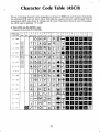
Character Code Table (ASCII) . _.. __ ... _
_ __ . _ .. _................................ 42
Specifications .................. _... _.... _ . . . . . . . . . . . . . . . . . . . ... . . . . . . . . . . . . . . . .. 46
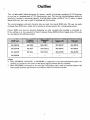
Outline
,,.
This is a lightweight, high-performance dot printer, capable of printing a maximum of 160 characters
on one line at a printing speed of 150 characters/sec. max. The two-way shortest-distance method is
adopted to increase its processing capacity. Fan-fold paper having a width of 5 to 15 inches, or paper
sheets (letter pad, etc.) can be used for printing with this machine.
The control programs and print character data are made into several ROM units. The user can easily
exchange these ROM units, which can be utilized as terminal printers for corresponding systems.
Certain ROM units must be selected, depending on what computer this machine is connected to.
If the mathine is to be connected to Sharp Computer Series MZ80, different signal cables, I/O cards,
etc. are required for different models.
MZ-8BP4R
MZ-80B
MZ-80EU
MZ-8BP4C
MZ-8PB51
MZ-8AP4R
MZ-80A
MZ-80AEU
MZ-8BP4C
MZ-8BP51
MZ-8KP4R
MZ-80K
MZ-SOI/O
MZ-8KP4C
MZ-8KP41
.-
..
--+~~~~~~+~~~~~---j
MZ-8SP4R
(Notes)
l. When MZ-SBP4R, MZ-SAP4R or MZ-8KP4R is connected to the above-mentioned system, the
machine is actuated by the control of the Sharp original software for the computer.
2. When MZ-8SP4R is mounted on this machine, this machine can be used as a terminal printer with
8-bit parallel interface specification in accordance with the Centronics System.
1
Cautions for operation
• Installation
• Do not install this machine in the following places.
Humid place, excessively dry place
Place exposed directly to sunlight
Dusty place
Extremely hot/cold place
Place with a lot of vibration
• Install this machine as horizontally as possible.
• Do not install this machine near equipment generating noise. Further, different power source
fnust be used for such equipment, since wrong operation may be caused if the same power source
is employed.
• Voltage of power source used for this machine must conform to the specification on the rating
plate on the back of the machine. Do not connect other power source, or else trouble may be
caused.
• Connect/disconnect the ROM unit when power is turned off.
• Cautions during operation
• Do not touch the printing head during operation.
• If water or other liquid or metallic articles such as needles and pins should enter this machine,
turn off power immediately, unplug the power cord, and contact the dealer. If the machine is
opeHlted under such a condition, accident may be caused.
• Do not print characters when printing paper or cartridge ribbon is not inserted. Otherwise, the
printing head may be damaged.
• Proper paper feeding function must be selected for specific paper used for printing .
. Fan fold paper
Tractor system
• Paper sheets
Friction system
The simultaneous use of the two systems will cause clogging of paper. When fan fold paper is
used, pull the paper release lever backwards to carry out tractor feed. (See page 7)
• Power cord
• Do not damage the power cord by placing it under a desk or chair, or by compressing it between
two articles.
• It is dangerous to use damaged power cord. Furthermore, be sure to hold the plug when unplugging the power cord.
• Impact
This machine consists of high-precision electronic components. Do not cause impact to this
machine, by hitting it with other articles or by dropping it.
• When this machine is not to be operated for a long time
When this machine is not to be operated for a long time, be sure to unplug the power cord from the
outlet.
• Stain
Wipe off stain on this machine with soft cloth impregnated with water or detergent. The use of
benzine, thinner, or other volatile substance, or insecticide will cause discoloration of the case.
2
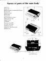
Names of parts of the
body
<D Rear cover
® Front cover
@ ROM unit holder (Accommodating ROM unit)
@ Control panel
@ Manual feed knob
@ Power switch
iZl Power socket
@ FG (Frame ground) terminal
@ Rating indication plate
®l Signal terminal
® Cell holder
[Front view]
@ Function switch (SW I)
® Function switch (SW2)
®> ROM unit (optional)
@ ROM unit model indication lahel
@ ROM unit arm
[Back view]
[Interior of ROM unit holder}
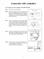
Connection with computers
(1) Connection with computer MZ-80B/MZ-80A
STEP 1. Turn off power for all equipment.
(Back of computer)
STEP 2. Install an expansion unit in the computer and
insert an I/O card into this unit. Insert the card in
Slit No.3 for MZ-80B (where 6 slits are available),
and in Slit No.2 for MZ-80A (where 4 slits are
available). The picture on the right shows correct
insert of the I/O card.
f-
-
-1-:------::=1e
el
•
I•
•
le
1/0 card
Fig. 1
STEP 3. Connect the connector on one end of the signal
cable to the signal terminal of the I/O card. Then,
fix the connector with the attached screws. Since
the connectors provided on both ends of the signal
cable have different shapes, do not confuse them.
Be sure to use the two screws for fixing the connector.
®L--------
Fig. 2
STEP 4. Connect the connector on the other end of the
signal cable to the signal terminal on the back of
the printer. Then fix the connector using the fixing
pins on both ends of the signal terminal.
Fix the COnnector using the fixing pins.
STEP S. Connect one cnd of the attached hraided wire to
the FG terminal of the printer, and the other end
to the FG terminal of the computer.
Do not fail to connect the braided wire.
Connect to the FG terminal
c:::J
of the computer.
0
...... ..x=~~==lg~~
Braided wire
Fig. 4
4
FG
r'
,
\i..
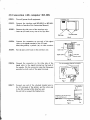
(2) Connection with computer MZ-80K
STEP 1. Turn off power for all equipment.
(Interface unit)
--;::c:=c::;n
STEP 2. Connect the interface unit MZ-80I/O to MZ-80K.
(Refer to Interface Unit Instruction Manual.)
STEP 3. Remove the side cover of the interface unit.
< Insert an I/O card in anyone of the five slots ..
Remove screws.
Side cover
Fto,5
STEP 4. Connect the connector on one end of the signal
cable to the signal terminal of the I/O card.
Match the polarity symbols (,.) on this occasion.
Connector
I1HImr~~~i+}- Guide
STEP 5. Put the side cover back on the interface unit.
1/0 card
Signal Cable
Polarity mark
F;g.6
STEP 6. Connect the connector on the other side of the
signal cable to the signal terminal on the back of
the printer. Fix the connector using the fixing pins
provided on both ends of the signal terminal.
fix the connector using the fixing pins.
STEP 7. Connect one end of the attached braided wire to
the FG terminal of the printer, and the other end
to the FG terminal of the interface unit.
Do not fail to connect the braided wire.
MZ-BOP4
J/
Connect to the FG terminal
of the interface unit.
~
.
Br~ed wire
Fig. 8
5
=
O~
FG
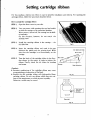
Setting cartridge ribbon
For this machine, endress ink ribbon is used to simplify installation and removal. For handling the
cartridge ribbon, follow the procedure described below.
How to install the cartridge ribbon
STEP 1. Open the front cover to your side.
STEP 2.
Turn on power while pressing the top feed switch
to shift the carriage to the prescribed position.
When power is turned off, the carriage can' be shifted manually.
On this occasion, however, do not touch the
printing head.
STEP 3.
Install the cartridge ribbon in the carriage - the
rear side first.
STEP 4. Insert the cartridge ribbon and mask in the gap
between the platen and the printing head. Make
sure that the cartridge is set horizontally on the
carriage,
STEP 5.
Ink ribbon and mask
(Front side)
,,
Turn the knob of the cartridge ribbon in the direction shown by the arrow, in order to tighten the
ribbon, Finally, check the ink ribbon for twisting
and crease.
Carriage
(Caution)
• Incorrect positioning of the cartridge ribbon may cause
wrong printing or destruction of the head,
• Replace the old cartridge ribbon with high-quality Sharp
cartridge ribbon, Do not use ribbon which does not conform to the requirement or which is poor in quality,
Otherwise, trouble may be caused,
Head mechanism
Fig, 10
(Front side)
Turn in the
direction
of arrow,
(Rear side)
Fig. 11
6
Setting paper
F an fold paper or paper sheets whose width is 5 to 15 in. can be used for this machine.
• Specification for paper
Paper width
Number of copies
;
Paper
thIckness
(Note )
Total thickness
I part
Copy
paper
5 in. - 15 in.
5 in. - 15 in.
Original + 2 copies
I part only
(Copying not allowed)
0.23mm max.
45kg - 60kg
Original
35kg - 45kg
Copy
35kg - 45kg
45kg - 60kg
(Notes)
• Weight (thickness) of paper in kg indicates the weight of 1000 sheets of AD-type paper.
• Do not print characters outside the paper, or the head may be damaged.
• Setting the assistant guide
In order to make the now of printing paper smooth, install
the attached assistant guide.
I nsert the tip of the assistant guide into the holes on the
right and left sides of the back paper feeding mechanism
section.
• On this occasion, connect the lead wire from the assistant guide to the FG terminal of the main body. Thus,
wrong operation of the equipment caused by static
electricity generated during paper feed can be avoided.
Install it correctly as shown in Fig. 12.
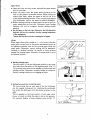
• Setting paper
Fan fold paper
STEP 1. Pull the front cover to your side, and turn the
paper release lever to your side.
STEP 2. Pass the paper from the back of the assistant
guide as shown in Fig. 14. Insert the end of the
paper beneath the platen, pull the manual feed
knob, and turn the knob until the end of the
paper comes out of the printer by about 10 cm.
STEP 3. Turn the paper release lever backwards, and
insert the sprocket pin in the feeding hole of the
printing paper. Confirm that the printing paper
is set to the sprocket pin in parallel. At this
time, release the sprocket lock lever by pulling
it to your side to adjust the tension and position
of the printing paper. After that, set the
sprocket lock lever back to the original position.
STEP 4. Put the printer cover back, and finish setting the
printing paper.
7
Assistant guide
Fig. 12
Paper sheets
.".
• Open the front and rear covers, and pull the paper release
lever to your side.
• Insert the paper from the paper guide provided on the
back of the printer mechanism section. While pulling the
manual feed knob, adjust the paper so that its end is set
at the desired printing position. Then, turn the paper release
lever backwards, and set the paper to achieve parallelism.
• Before starting printing on paper sheets, be sure to pull the
paper release lever to your side. Otherwise, paper feeding
function will not be actuated, thereby causing double
printing.
• Set the paper to the left edge. Otherwise, the *PE detection
function will not be actuated, thereby causing breakdown
of the equipment.
*means the function to detect running-out of paper.
(Note)
When paper sheets with a width of 5 - 6 in. in used, slide the
paper guide on the back of the printer mechanism section to
its rightmost position, and set the printing paper along this
paper guide. Otherwise, correct feeding will be hampered,
resulting in deviated printing. Be careful to avoid printing
outside the printing paper. Normally, the paper guide is set at
its leftmost position.
4
,
Paper sheets (5~6 in. wide)
F=:;;/:.-.: ==.~, -:,
,,,,
==-=:!...J
Paper guide
Fig. 16
• Setting printing paper
The top surface of the fan fold paper shall be set in a position lower than the surface of the assistant guide. (Fig. 17)
The printing paper must be set parallel to both printer and
printing section. Otherwise, accurate feeding is hampered,
therehy causing trouble due to clogging of paper.
Fan fold paper
Fig. 17
• Setting form position of printing paper
The top printing line on each rage of the fan fold paper
can be roughly determined by matching the perforated
line of the fan fold paper with the platen as shown on the
right.
This is regarded as the form position of each page, when
power is turned on while the paper is set in this position.
For memory backup of form position, refer to page 14.
a
Fan fold
paper
---
------.;;-
o .{=;.===={
~=""'~==:!,..
Fig.18
8
Matching
perforated line
Platen
,,
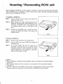
Mounting/Dismounting ROM unit
When installing the ROM unit in this machine or replacing it, follow the procedure described below.
Since the ROM unit is susceptible to electric shock, such as static electricity, adequate precautions
must be taken in handling Or storing it.
• Installation of ROM unit
STEP l. Turn off power for this machine, and remove the
ROM unit holder cover.
STEP 2. ,While keeping the model indication label oJ the
ROM unit facing upwards, set the ROM unit to the
connector in the holder part. Then insert the unit
by applying uniform force to both sides of this
unit.
STEP 3. Confirm that the ROM unit is inserted correctly,
and put the ROM unit holder cover back in its
original position.
Fig. 19
• Removal of ROM unit
STEP l. Be sure to turn off power for the main body.
STEP 2. Pull the ROM unit from the ROM unit holder by
holding the arm.
STEP 3. The removed ROM unit must be stored in an
electrically conductive bag so as to protect it from
breakdown caused by static electricity, etc. Since
optional ROM units are packaged in conductive
bags, use these bags for storage.
F;g.20
(Caution)
• When a ROM unit is replaced or newly installed, renew the setting of the function switches.
(See page I 1)
• When memory backup function is actuated, set the position of the top printing line again.
(See page 14)
• Incorrect connection of the ROM unit will hamper normal operation and may cause trouble.
Utmost care must be taken since, in the worst case, the ROM unit may be broken.
9
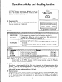
Operation switches and checking function
,
"
• Power switch
The power switch is indicated by "POWER" on the rear
side of this machine. Press this switch towards the "ON"
side (" I") in order to turn on power..
POWER
Fig. 21
• Opl'ration switches
.
On the control panel on the front side of this machine,
there are 3 switches and 3 indicators.
Cl ON LINE
11 =NO PAPERiI Cl
ON/OFF LINE IITOP OF FORMiI
I
I
I
I
POWER
LINE FEEO
I
I
Fig.22 Indication on the control panel
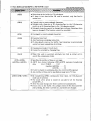
Switches
TOP OF FORM
Feeds paper to the designated form feed position. (See Note I)
1--=-=-=---=-=---=-=-=-==-----1--
LINE FEED
Changes lines. When this switch is pressed once, feed operation for
~ _ _ _ _ _ _--I-_.::o::n~IY one line will be carried out. (See Note I)
ON/OFF LINE
• Selects ON-LINE or OFF-LINE.
• Every time this switch is pressed, ON-LINE or OFF-LINE is selected
alternately.
• No operation will be caused when the carriage is operated or during
line feed.
Indicators
POWER
Lights when power is turned ON.
(Red light)
ON LINE
Lights when ON-LINE is selected.
(Green light)
NO PAPER
Lights when there is no printing paper left. (See Note 2) (Green light)
(Note 1) This switch cannot be operated when the printer is ON-LINE.
(Note 2) When the PE detecting function is neglected by the use of software, printing can be continued even if the NO PAPER indicator is lit. For normal operation, actuate the PE safety
function, in order to prevent breakdown.
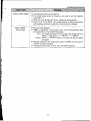
• Self-diagnosis function (incremental printing)
When power is turned on while the line feed switch is pressed, the self-diagnosis routine will be
actuated to print all characters sequentially. If it is desired to stop this function, turn off power.
When self-diagnosis function is utilized, use paper with a width of 15 in. Otherwise, printing will be
made outside the paper, causing breakdown of the head.
• Override function
When the ON/OFF LINE switch is pressed in PE condition, SELECT condition will emerge, cancelling PE and reading data for one line. After printing, OFF-LINE will be selected again. This function
can be effectively utilized when paper sheets are used, provided that ROM unit MZ-8BP4R or
MZ-8SR4R is employed.
10
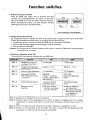
Function switches
• Position of function switches
When the ROM unit holder cover is removed from this
machine, two multiple-switches are found on the lower
side of the ROM unit. These are called "function switches".
Before operating the printer, set these function switches
following the procedure described below.
SW2
SW1
~~~~~~~~~~
IEx.1
SW2-8
J
J
lEx.!
SWI-2
Fig. 23 Switch Nos. of function sw.ltehes
• Setting the function switches
By setting the function switches, the state of the printer after turning on power can be determined.
Follow the procedure described below, in operating the function switches.
I. Confinn that power is turned off while the ROM unit is connected to MZ-80P4.
2. Next, set the function switches representing the desired operations.
3. Turn on power for MZ-80P4.
(Caution) Do not operate the function switches while power is turned on. Otherwise, wrong operation
or trouble may be caused.
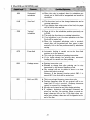
• Functions of function switch SWl
The switch SW I has common functions for any ROM unit.
SWl-l
Designates the size of
one page (See Note 1)
66 lines/page
SW\-2
Designa tes the distance
between lines (See Note 2)
Distance: 1/6 in.
Distance: 1/3 in.
SWl-3
Selects 0 print indication
"Q"indication
"0" indicatior
SWI-4
Processes ON-LINE/
OFF-LINE after power
is turned on
ON-LINE
("Select" condition
emerges, and the green
light goes ON.)
OFF-LINE
(The green light goes
OFF.)
SW\-S
Selects printing system
136 characters/line
mode (Pica pitch)
160 characters/line
mode
Memory backup
function
• Memory backup
function is actuated
by cell. (Note 4)
• Memory backup is
no! carried out.
• The position selected
when power is turned
on is regarded as
form position.
72 lines/page
.
-- ----
i
SW\-6
-
--
I
_.
(Note l) Setting can be changed by the use of software.
(Note 2) Priority is given to the designation by the switch in regard to changing lines. For example,
compression by control code will be 2/9 inch when the distance between lines is set at 1/3
inch.
(Note 3) In the I 36-character mode, the space dot between characters is expanded to 2 dots.
(Note 4) If there is not electricity in the cell when this switch is turned ON, the position selected
when power is turned on will not become fonn position.
11
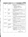
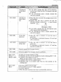
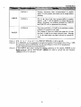
• Functions of function switch SW2
The functions of switch SW2 vary, depending on ROM units used in this machine. Set tHe switch,
after carefully confIrming the following.
When ROM unit MZ-8BP4R is used
\,
···~~:tM:
(':,~,I'-,
'L," ~ t _);,,,,, :.:,!:
·l. ·::,''':····/:·'~''·'· .',;·
:',,)11"": "I"; ,I",," L ,-"
ill
SW2-\
I",
',1,-
i"""
;I~,,/II~" ,,',' ,;"1
1
,[.,'
;11_':';,'::, """
. .,}'[,I',
. . . . . .,,' ·····'9l!!
I'... "":"'" I""
,,:...,,'~
-~
'.
......
,
. . ·; . I: . .····,·'···:i".'~
Se1ects operation
Starts printing operation, and
when the buffer is
full.
does not carry out line feed upon
completion of printing.
Starts printing operation, and
carries out line feed upon completion of printing.
SW2-2
Sets NL (new line)
function.
If carriage return code (ODH) is
received, line feed is not carried
out upon completion of printing .
If carriage return code (ODH) is
received, line feed is carried out
upon completion printing.
SW2-3
Processing of DCII
DC3 code,
Receives and processes device
control "DCl (fode and "DC3"
code.
Ignores device control "DC I "
and "DC3" codes.
Automatic WAIT
function
(Refer to Note I)
Automatic WAIT is effected,
depending on the number of
fonts in one line.
Stops automatic WAIT function.
(Refer to Note 2)
------
SW2-8
.
---
_-
._--
t!
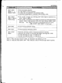
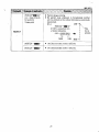
When ROM unit MZ-8KP4R or MZ-8AP4R is used
'"I~
\:,'. ,·:,;"
iI'I~:).'!'~,1t' i~iloli'!.
",_..Ii.H.HH
'1 11:'11'
SW2-\
SW2-2
SW2-8
"" ..
when the buffer is
full.
does not carry out line feed upon
completion of printing.
. Processing of paper
detecting function
signal (PE)
Receives paper detector sign.l .s
effective.
Ignores paper detector signal.
(Refer to Note 2)
Automatic WAIT is effected,
depending on the number of
fonts in one line.
Stops automatic WAIT function.
(Refer to Note 2)
Automatic WAIT
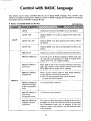
When ROM unit MZ-8SP4R is used
,'I "
.. ~" ...
);'1,"
'11
'
;,'I!,
11,,,
':,,::"·:.j'i'
Starts printing operation, and
(Refer to Note I)
,""_ .',
:t.l".i,;,"~,~ ,,;'~,r:,l:";·n!;;,
Se1ects operation
function
,'''''1
.. . . ,. . ····,1·".·
. . . . . . ;"
. ,·;;···,HN•. ,· · .· · ·, . . .............
,
"
1
Starts printing operation, and
carries out line feed upon comple.
tion of printing .
!trr
'.r:;)'·:
";,,,,'",,),iON:
i;:
, ''' .. ,')"1'
"
'Ii."!, ":,_:11,:'
i
[>"I"l"
SW2-\
Selects operation
when the buffer
is full.
Starts printing operation, and
does not carry out line feed upon
completion of printing.
Starts printing operation, and
carries out line feed upon completion of printing.
SW2-2
Setting of NL
function.
Carriage return code only designates printing, but does not carry
out line feed upon completion
of printing.
Carriage return code (ODH) carries
out line feed completion of
printing.
SW2-3
Processing of
.
._--
-------
DCI/DC3
Does not receive device control
DCI or DC3 code.
ASCII standard character
specification.
International character specifi.
cation (Set by SW2-S through
SW2-7).
...
SW2-4
Selection of
character
specification
SW2-S'
SW2-6
SW2-7
Selection of nation-
...
•
_-----
.
character
SW2-8
Automatic WAIT
function
(Refer to Note I)
!
-
Refer to a separate table.
• SW2--4 must be kept "OFF".
wise specification
of international
-
Receives device control DCI and
DC3 codes.
_
Automatic WAIT is effected,
depending on the number of
fonts in one line.
12
.
Stops automatic WAIT function.
(Refer to Note 2)
-
•
\,
Languagewise international character setting
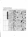
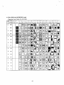
For differences in languagewise international characters, refer to the Character Code Table on page 45.
(ASCII standard)
ON
French
OFF
OFF
ON
ON
German
OFF
ON
OFF
ON
Danish
OFF
OFF
OFF
ON
Swedish
OFF
ON
ON
OFF
Itali~n
OFF
OFF
ON
OFF
Spanish
OFF
ON
OFF
OFF
(Note 1) Automatic WAIT
When automatic WAIT function is effected, the dot duty calculating routine is actuated to automatically creat lag time when the capacity of the head is exceeded.
When stopping the automatic WAIT function, pay attention to what is printed. Do not use image print
or quasi-graphic pattern when the automatic WAIT function is stopped. Further, avoid printing the
same character cOl1tinuously. Especially, limit the number of fonts per minute to less than 70,000 dots.
(Note 2)
Not applicable to incremental printing.
13
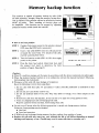
Memory backup function
This machine is capable of memory backup by cells. (Cells
are sold separately, though.) When the memory backup function is effected, form position will not be affected by turning
on/off of power. Thus, handling of fan-fold paper can
be simplified. This function can be stopped by operating
pertinent function switch inside the machine.
Install
2 cells
!SU
.,
Fig. 24
• How to set form position
STEP 1. Confirm that power source for the printer is turned
OFF when the ROM unit is connected.
SW1
SW2
STEP 2. Insert 2 dry cells (SUM-3) into the cell case provided inside the main body. For details of the cells,
read the cautions given below.
STEP 3. Turn the function switch (SWI-6) ON, then supply
power to the printer.
STEP 4. Press the form feed switch. After form feed, pull
the manual feed knob to determine the form
position of paper. (See page 8)
Set SW1-6 at "ON"
pOSitIOn. -
Fig. 25
(Caution)
• When PE condition emerges, set the paper in accordance with the above-mentioned procedure again.
• When the memory backup function is to be utilized, do not turn the manual feed knob. Otherwise,
form position may be deviated.
• Wrong use of dry cells will cause leakage or breakdown.
Keep the following in mind when using them.
\. Set the cells with their plus (+) and minus (-) sides correctly positioned as indicated on this
machine.
2. Do not mix new and old dry cells for use.
3. Do not use different kinds of dry cells. They may differ in voltage, even if their shapes are the
same.
4. Remove dry cells from this machine, if they are not to be used over a long period of time.
5. There are charging-type and non-charging-type cells.
Read the cautions written on them, before using these cells.
• Do not turn off power when the following operation is carried out during memory backup.
Otherwise, form position may be deviated .
• Line feed
• Form feed operation
• If ROM units are exchanged during memory backup, readjust form position of paper.
• Replace old cells with new ones every year, although the life of ce\1 differs depending on internal
discharge and frequency of use. (Trouble may occur to some cells, due to corrosion, etc.)
14
•
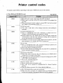
Printer control codes
The printer control differs, depending on the kinds of ROM units used in this machine,
(OOH)
• When CR code is input, data inside the buffer is printed.
• When there is not data before CR code is received, the carriage does
not shift.
• When the internal function switch is turned OFF, linefeed is carried
out. (Refer to the function of SW2-2.)
(OAH)
• Line feed code.
• This code is used both as line change instruction and printing instruction.
(OBH)
• Vertical tabulation (VT)
• This is a multiple-line feed code. Operation is carried out in accordance with the tabulation previously set in RAM.
• Printing instruction code. When this VT code is received, stored data
will be printed, and after that, automatic feeding will be carried out
to the line previously set by tabulation.
• Tabulation in excess of the set page length will be ignored, and the
same operation as by (OAH) code will be carried out.
(OCH)
• Form feed
, • This is a multiple-line feed code. Automatic feeding is carried out to
the form feed position set in the memory.
• This is also used as printing instruction.
• If the buffer already has printing data, the data will be printed first
before automatic feeding is started.
---------------------
------------------~
-----~------
-----------------------
(09H)
• Horizontal tabulation
• When this code is received, data for tabulation set in RAM will be
reorganized, for storage in the buffer.
• Excess over the maximum number of characters designated by (lB)+
(J 9H)+(HEX) will be ignored.
• This is not a printing inspection.
(11 H)
• Device control 1 (DC I)
• This is a printer select instruction code.
• This code can be ignored by manipulating the internal function
switches.
• When the data are received, the on-line indicator lights up.
(12H)
• The I36-character/line mode will be selected.
• When this code is received, the carriage returns to its home position
for line feed, and the I 36-character/line mode will be selected.
15
(MZ-SBP4R)
~~~N
(13H)
1 - - - - - - - - - + - - - - - - - - - - -------
•
I
• Device control 3 (DC3)
• This is a printer deselect instruction code.
• This code is ignored when the printer is in DESELECT mode.
(l4H)
• Instruction to cancel enlarged characters.
• This code can be set in any place in the data code string.
• This code is ignored when the 136 character/line mode is selected.
(ISH)
• Cancel code
• This cancel code clears printing data before this code is received as
well as SO/SI.
• This code is not applicable to image printing.
(OEH)
• Shift out (SO)
• This code is enlarged character instruction, and can be inserted in
any place during data receiving.
• Data after receipt of SO is effective until SI code is received. They
will not be cancelled by changing lines.
• Even if SO code is received after the previous SO code is received and
before SI code is received, the SO will be ignored.
(OFH)
• Shift in (SI)
• When this code is received, the printer prints the data stored in the
buffer, makes the carriage to return, and changes into the 160
characters/line mode.
• This code will be ignored when the 160 characters/line mode is
already selected.
(IBH)
• Escape code
• HEX code following this code controls various printers.
.,
(1B)+<OO)
•
•
•
•
•
(lB)+(02)
• Cancels compression mode.
• When this code is received, automatic line feed is started. Line feed
will take place every 1/6 inch.
(IB)+(] 9H)+(HEX)
• The <HEX) value following (lBH)+( 19H) designates the maximum
number of printing characters.
• When the I 36-character mode is specified, 0 < HEX -;;; 136
• When the l60-character mode is specified, 0 < HEX -;;; 160
• Not applicable to image printing.
(lB)+(OSH)
• When this code is received, line reed will be carried out twice. For
example, if 1/6 inch feed is specified before tbis code is received,
1/3 inch line feed will be started_
Compression mode
After this code is received, 1/9 inch line feed will be made.
This code will not be cancelled until (I B)+(02) is received.
This code can be received any time during data receiving.
This code will be ignored when 1/9 inch feed is already selected_
16
(M7_RRP<1 J;I
:t~:~:
'''I i,
;:';'
I~" "",""""~'"''
~i
'''/'' c,
I
',_"1,"';';,11,;1",'11""1
",:""
"
"",><
"C.i,,}C(
,
(lB)+(06H)
• Code to cancel (I B)+(OSH)
(lB)+(08H)
• When this code is received, PAPER EMPTY (PE) will be ignored.
(I B) +<09H)
• Makes PAPER EMPTY (PE) signal effective.
~"'"
(lB)+( I IH)+<HEX,)
+ ..... +(HEXn)+(OO)
,"
-
(IB)+(]4H)
• Sets vertical ta bulation.
• Following (lB)+(1IH), transfers tabulation setting position in
hexadecimal number.
• Upon completion of tabulation setting, transfers (00) NULL code.
The maximum tabulation value shall be [specified page length -I] .
Example: When page 'Iength is 72 lines, tabulation value will be 71
or less.
• Tabulation value can be set in a random manner.
• Tabulation value is an absolute value from home position.
• Clears vertical tabulation setting.
(1 B)+( 12H)+<HEX)
• Sets the number of lines per page.
• Any number up to 72 lines can be set in <HEX) following (lB)+
( 12H>.
• Any number in excess of 72 liens will be ignored.
• 0 line will be ignored.
• When this code is received, form feed will be executed automatically.
(lB)+( 13H)+<HEX,)
+..... +<HEXn )+( 00)
•
•
•
•
(IB)+(ISH)
f-----
Sets horizontal tabulation.
n value can be up to 135 lines.
n values can be transferred in no particular order.
Upon completion of tabulation setting, NULL code shall be transferred.
• Clears horizontal tabulation setting.
-
(I B)+( 18H)+<HEX,)
+<HEX,)
+<Data string)
• Image print instruction.
• The number of image data to be transferred following (I B)+O 8H)
shall be transferred in 2 bytes: (HEX,)+(HEX,). (HEX,) represents
lower 8-bit data, while (HEX,) represents upper 8-bit data. If the
number of transfer bytes is 16 bytes, (I B)+( 18H)+ ( I OH )+(OOH)
+( 16-byte data).
When this code is received, line feed is started automatically after
printing the 16-byte data.
• This code will be ignored when <HEX,)+<HEX,) = (00)+(00).
17
•
~WhBjeln~R~oIMHln~n~it~M~Z~-E83K~P4~R~o~r~M~Z~-8~A1P~4~Rji~S~UCsetd~E~~~tF~~~~~(~M~Z-8KP4R/MZ-'8AP4R)
•
(ODH)
• Prints data in the buffer by CR code input.
• If there is not data before CR code is received, only line feed is
carried out.
(OBH)
• Control code to create enlarged characters.
• Enlarges each character as 80 characters/line (in the l60-character
mode) or as 68 characters/line (in the I 36-character model.
• Enlarged characters cannot be changed into ordinary characters when
lines are changed. (The function cannot be cancelled.)
(OCH)
• Command to cancel enlarged characters.
(OFH)
• Executes form feed.
• Also functions as printing instruction.
• If data already exist in the buffer, feed operation is automatically
carried out upon completion of printing.
(09H)
• Compression mode (1/9 inch feed)
• Cannot be cancelled by changing lines.
(OAH) .
• When this code is executed, automatic line feed is carried out to
can cell the compression mode.
(09H)+(09H)+
(ASCII)H +(ASCII)L
• Specifies the number of lines on one page.
• ASCII (two bytes) following (09H)+(09H) expresses hexadecimal
data.
(Ex.) If HEX. . . .. 16H
transfers (ASCII)II ..... 31
(ASCII)L ..... 36
• If error IS found in continuous data, the control will be ignored.
• Any number of lines can be specified par page up to 72 lines.
(09H)+(09H)+(09H)
• By transferring (09H) continuously three times, the 160-character
mode can be selected.
• The mode when power is turned on can also be set the function
switch SW1-S.
• After the mode change, line feed is carried out automatically.
• If data exist in the buffer, the carriage returns to the home position
after printing, line feed is carried out, and modes are changed.
18
(MZ-8KP4 R/MZ-IlAP4R)
(09H)+(09H)+(OBH)
• I 36-character mode can be selected.
• The mode when power is turned on can also be set the function
switch SWl-S.
• After the mode change, line feed is carried out automatically.
• If data exist in the buffer, the carriage returns to the home position
after printing, line feed is carried out, and modes are changed.
(OBH)+(OBH)+
(Data string)
• Permits image printing.
• (OBH) is transferred continuously twice, and the hexadecimal data
are transferred in 2-byte ASCII expression.
(Ex.) For image printing of l6-byte data, data string will be as
follows: Data string --+ (HEXl)+ ...... +( HEX16)
(Note) (HEXl) - (HEXI6) above is hexadecimal data in ASCII
expression.
• Printing instruction for image print is given by ODH, as in the case of
ordinary character printing.
• If continuous data have an error, this code will be ignored.
19
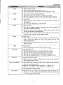
''':'
09H
Horizontal
tabulation
• When this code is received, data for tabulation previously set in RAM will be reorganized and stored in
the buffer.
OAH
Line feed
• This functions both as line change instruction and as
printing instruction.
• If no printing data exists prior to line feed, the paper
will be fed by only one line.
, OBH
Vertical
tabulation
• Paper is fed to the tabulation position previously set
in RAM.
• This code also functions as a printing instruction.
• If no tabulation is set, the same operation as in Line
Feed will be carried out.
• When the horizontal tabulation code is received,
stored data will be printed and then paper is automatically fed to the line predetermined by tabulation
setting.
OCH
Form feed
• Automatic feeding is carried out to the form feed
position set in the memory.
• This code also functions as printing instruction.
• If the buffer already has printing data, automatic
feeding will be carried out after printing.
ODH
Carriage return
• Printing instruction code
• Whether to change lines after printing can be also
determined by the internal function switch.
• The carriage will not be shifted if there is no data
before this code is received.
However, if the internal function switch SW2-2 is
turned OFF, line feed will be carried out.
OEH
Shift out (SO)
• This is an enlarged character instruction code.
• Printing characters after SO are received will be enlarged until SI code is received. (Ordinary characters
cannot be resumed by changing lines.)
• SO code can be input in any place during printing.
• If ordinary characters and enlarged characters are
mixed on one line, the position where a certain enlarged character falls on the l35th digit when converted into ordinary characters will be regarded as the
end of the line.
20
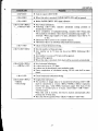
T' - - - - - - - - - - - - - - - -
I
I
OFH
Shift in (SI)
• Input of SI code cancels enlarged characters. :ters.
• When SO and SI are mixed, printing will be carried
out as follows.
A) Input SO+"A"+CR+LF
Printing: A (enlarged character)
B) Input SO+"A"+SI+"A"+CR+LF
Printing: A A
IIH
Device
control I
(DCI)
• This is a printer select instruction code.
• This code can be ignored by the operation of the
internal function switch.
• When this code is received, the ON-LINE indicator
will go on.
l3H
Device
control 3
(DC3)
• This is' a printer deselec1 instruction code.
• This code will be ignored when the printer is executing deselect operation.
• This code can be ignored by seIecting the relevant
function switch.
ISH
Cancel code
• This is a cancel code, which cancels data in the buffer
stored before this code is received. SO/SI code is also
cancelled.
• Nat applicable to image printing.
ESC+(OOH>
Compression
mode
instruction
• After this code is received, 1/9 inch line feed will be
carried out.
• This code cannot be cancelled until ESC+02H is
received or power is turned off.
• This code can be received anywhere during data receiving operation.
ESC+<02H>
Cancellation of
compression
mode
• After this code is received, 1/6 inch line feed will be
resumed.
After automatic feeding is executed to the next line
position, 1/6 inch feed will be started.
ESC+(04H)
13 6-character
mode instruction
• When this code is
the home position
will be selected.
• Printing after this
following printing
characters. (Ex.)
[ESC=IBH]
received, the carriage returns to
and then the 136-character mode
code is received will have the
construction - Or gap between
HH
[DOG~
21
= 2 dots
I
ESC+(03H>
I 36-character
mode instruction
• If the buffer contains data, they will be printed before line feed. After that, the 136 character mode will
be selected.
• If the 136-character mode is already selected, this
code will be ignored.
160-character
mode instruction
• When this code is received, the carriage returns to the
home position.
• Printing after this code is received will have the
following printing construction - or gap between
HH
characters. (Ex.)
• If the buffer contains data, the 160-character mode
will be selected after printing them.
• If the 160-character mode is already selected, this
code will be ignored.
ESC+(05H>
1/3 line feed
instruction
• After this code is received, 1/3 inch line feed is
carried out.
If compression is instructed, however, 2/9 inch feed
will be carried out.
ESC+<06H>
Cancellation of
1/6 line feed
• After this code is received, 1/6 inch line feed is
carried out.
If compression is instructed, however, 1/9 inch line
feed will be carried out.
ESC+<OSH>
• Ignores signals from the paper detector.
ESC+(09H>
• Receives signals from the paper detector as effective.
ECS+(\ IH)+
<HEX,)+ .... +
<HEXn)+ <OOH)
• Carries out vertical tabulation setting.
• Tabulation can be set by the hexadecimal number following ESC+(\ IH>.
• Tabulation value shall not exceed 71.
(When One page contains 72 lines.) (Refer to Note I)
• Tabulation can be set in a random manner.
• Tabulation value is an absolute value from the form position on the
printing paper.
ESC+(\ 2H)+
<HEX)
•
•
•
•
Sets the number of lines per page.
The num ber in excess of 72 lines is ignored.
0 (zero) is ignored.
When this code is received, form feed is automatically carried out.
22
I
~
•
ESC+(]3H)+
(HEX1) +..... -+
(HEXn)+<OOH)
•
•
•
•
ESC+(]8H)+
<HEX1 )+(HEX, )
+<Data string)
• The number of image data following (]B)+(] 8H) shall be transferred in 2
bytes: (HEX1)+(HEX,).
• The number of transferred bytes shall be expressed in 2-byte hexadecimal
number. (HEXl) shall represent lower 8-bit data whereas (HEX2) upper
8-bit data.
(Ex.) When the number of transferred bytes is 16 bytes .
(I BH)+<18H)+(l0H)+(Q0H)+(\ 6 byte data)
.,
Sets horizontal tabulation.
n value shall be 135 at maximum.
n values may be transferred in no particular order.
Tabulation setting shall be completed with the NULL code.
ESC+(]4H)
• Clears vertical tabulation setting.
ESC+06H)
• Clears horizontal tabulation setting.
ESC+(] 9H>+
(HEX)
•
•
•
•
Sets the maximum number of characters printed on one line.
Specifies the number of characters with (HEX) fonowing ESC+(] 9H).
In the 160-character mode, 0 < HEX ~ 160
In the I 36-character mode, 0 < HEX ~ 136
(Note I) When one page contains 66 lines, the tabulation value shall be up to 65.
(Note 2) Character codes shall be 20H ~ 7EH. Character codes of 7FH and larger shall be ignored.
23
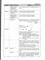
Control with BASIC language
This printer can be easily controlled with the use of Sharp BASIC language. Note, however, that
different computers employed have different versions of BASIC language and commands to the printer.
For details, refer to the BASIC Language ManUal .
• BASIC for MZ-80B/BASIC for MZ-80A
LIST/P
LIST/P
Outputs all the lists in the BASIC text to the printer.
LIST/P-IOO
Outputs BASIC text as far as statement No. 100 to the
printer.
LIST/P 100-500
Outputs BASIC text from statement Nos.IOO to 500 to
the printer.
LIST/P 500-
Outputs BASIC text above the statement No.500 to the
printer.
PRINT/P A$
Outputs the contents of string variable A$ to the printer.
PRINTjP CHR$ (N)
If 32 ~ N ~ 255, N shall be regarded as ASCII code, and
the character corresponding to it shall be output to the
printer. IF N = 65, "A" shall be printed.
PRINT/P CHR$(5)
Form feed
Paper shall be fed to the top (form position) of the next
page. The function of the printer control button (TOP
OF FORM) will be carried out by software.
PRINT/P CHR$(6)
Initialization
Resets all the control codes to their initial positions.
At this instance, form feed is carried out.
• The 136 characters/line mode can be resumed.
1/6 inch line feed is selected.
PRINT/P CHR$(16)
Cancellation of lineto-line compression
mode
1/6 inch line feed is selected.
PRINT /P CHR$(l7)
Line-ta-line
compression mode
1/9 inch line feed is selected.
PRINT /P CHR$(18)
Enlarged character
instruction
The mode in which the present printing character size is
doubled is set. If the 136-character mode is set presently,
the 68-character mode will be selected. If the 160character mode is set presently, the 80-character mode
will be selected.
PRINT/P
24
!"'"r~_m(MZ-80B/80A)
'i!I"
PRINT/P
..
PRINT/P CHR$(19)
Cancellation of
enlarged characters
The 136-character mode or 160-character mode is resumed.
PRINT /P CHR$(20)
Character-ta-character
compression
The space between characters is compressed.
(The 160-character mode will be selected.)
PRINT/P CHR$(21)
Cancellation of
character-ta-character
compression
Cancels character-ta-character compression.
(The I 36-character mode shall be selected.)
IMAGE/P "A"
ASCII code of character" A", or bit pattern corresponding to 41H, will be printed in the vertical direction.
LSB -+ •
IMAGE/P "A"
)41H = 01000001
IMAGE/P
t
t
MSB
LSB
.
0
This dot is
printed.
0
0
0
0
MSB .....
•
0
IMAGE/P CHR$(65) equals IMAGE/P "A". This printint is called the "Bit Image Mode".
(Note 1) Bit image data are given as string data.
(Note 2) The length of bit image data shall be 960/line.
If the data exceeds 960, the remainder will be
printed after line feed.
(Note 3) BASIC for MZ-80A does not have this [MA GEl
Pcommand.
COpy /P command is used for output of pattern indicated on the computer CRT screen (or more strictly,
data in V-RAM region) to the printer as it is displayed
on one screen.
The following four copy formats are available.
However, BASIC language for MZ-80A does not have
COPY/P2, COPY/PJ, or COPY/P4 commands.
COPY/P
COPY!P I
If the CRT screen displays data in V-RAM region for
characters, the data on one screen win be output to the
printer.
COPY!P 2
Outputs one-screen data accommodated in graphic
region lout of 2-screen V-RAM regions for graphic use
(graphic region 1 and graphic region 2) to the printer,
and carries out bit image pattern printing.
25
COPY/P
PAGE/P
COPY/P 3
Outputs one-screen data accommodated in graphic
region 2 to the printer, and carries out bit image pattern
printing.
COPY/P 4
OR of the bits of the data accommodat'ed in graphic
regions I and 2 will be regarded as output data to the
printer. Therefore, the patterns obtained by COPY /P2
and COpy /P3 will be superposed for printing.
COPY/PN
The value. specified by N shall be the maximum number
of lines to be printed on one page.
The number of lines here means the value for 1/6 inch
line feed. N shall be an integer selected from I through
72. In the initial stage, one page is allowed to contain 66
lines.
(Note I) If M = 0 - 4, 7 - IS, or 22 - 31 in PRINTjP CHR$(M), it will be ignored.
(Note 2) M in CHR$(M) can be expressed in hexadecimal number. For example, since (32)'0 = 20H,
the indication shall be CHR$($20). $ in the parentheses in front of the hexadecimal
number indicates hexadecimal representation.
(Note 3) If NO PAPER takes place during the printing operation of the printer, ERROR in the
BASIC language will be NOT READY I ERR65 I in order to actuate the over function.
I ERR67 Iwill not be indicated.
26
-
._- - -
--
-~
--
-~
~-~
~-~
- - - .--.
--
• BASIC for MZ-80K
LlST/P
LlST/P
Outputs all the lists in the BASIC text to the printer.
LlST/P~IOO
Outputs BASIC text as far as statement No.1 00 to the
printer.
LlST/P
100~150
Outputs BASIC text from statement Nos.1 00 to 500 to
the printer.
LlST/P
500~
Outputs BASIC text from statement No.500 on to the
printer.
PRINT/P A$
Outputs the contents of string variable A$ to the printer.
PRINT/P CHR$(N)
If 32 ~ N ;:;; 255, N will be regarded as ASCII code, and
the character corresponding to it will be output to the
printer. IfN = 65, "A" will be printed.
PRINT/P "m"
Form feed
Paper is fed to the top (form position) of the next page.
The function of the printer control button (TOP OF
FORM) will be carried out by the use of software.
t----- --.--.-- - - - -
PRINT/p "11"
Clear form
-----j
Cancels line-to-line compression and enlarged characters.
1---------+----------
PRINT/P
PRINT/P "0"
Enlarged character
instruction
The 80 characters/line mode 68 characterS/line mode
will be selected.
-----/---- - - - - - . - - . - -
-- --.--
PRINT/P "0"
Line-to-line
compression mode
1/9 inch line feed will be selected.
PRINT/P "DO XX"
(xx = number of
lines)
Page setting
• Designates the number of lines per page.
• One page can contain a maximum of 72 lines.
• The number of lines can be designated in hexadecimal
number.
(Ex.) If it is desired to print I1 lines on one page,
hexadecimal representation of 1I (OBH) shall
be transmitted.
PRINT/P "DD OB "
• If no designation is made by software, the number of
lines as designated by the function switch SW I ~ I will
be adopted (66 lines or 72 lines).
27
1-"""
'I"
"
PRINT /P"DDXX"
(xx = data string in
bit pattern)
Image print
• Permits image printing.
• Bit pattern data expressed in hexadecimal number
will be printed in the vertical direction as previously
determined.
(Ex.)
PRINT/p "DD 01"
If 0 I H is converted into
a binary indication,
OIH = 0000 000 I
PRINT/P
LSB ..... '
.~ ~This
o
o
o
-t a
- l t
MSB
LSB
dot is
printed.
o
MSB ..... o
PRINT/P " DDD "
• 160 characters/line mode is selected.
PRINT /P " aDD"
• 136 characters/line mode is selected.
28
, I\"
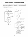
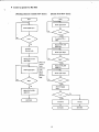
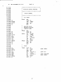
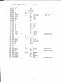
Example of control with machine language'
The example of program for controlling this printer with machine language is shown below. The
method of control varies, depending on the ROM unit used. The example shown below represents
reference subroutine program which constitutes the most basic part of the control.
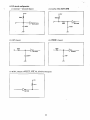
• Control as printer for MZ-80B/MZ-80A
[Concept of printer control I
[Printing data transfer routine I
Start
Start
. - - - - - - + 1 Checks BUSY signal
Is the printer
ON LINE?
BUSY signal input
IN A. (FEH)
No
No
Low level?
Transmits control
code or printing
data code to the
printer.
Transfers data
code
Yes
Is
~
Ace. - Data code
/ OUT (FEH), A
there
transfer
data?
No
Makes DATA STH
SAce. +- SOH
signal high.
/ OUT (FEll), A
BUSY signal input
IN A, (FE H)
High level?
Makes DATA STB
signal low.
Return
29
When the printer]
receives data
code, BUSY
[ signal becomes
high.
S Ace.
+-
oon
lOUT (FEH), A
•
••
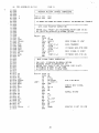
ZeD ASSEMBLER 88-7201
PAGE 01
· ......................... . ............ .
01 0000
1 1 •
02 0000
1
,
• 1
,
,
,
1
,
1 ,
,
,
,
,
,
,
I
,
,
r r
I
I
'
,
,
I 1
,
,
1 1 1 1 1 1
,
PRINTER MZ-80P4 CONTROL SUBROUTINE
· ...................................... .
03 0000
,
,
1
1
I
I
I
,
,
,
1
,
•
,
,
•••
,
•
,
,
,
••
,
,
•• 1
1
,
•
1
1
•
1
•
1
•
04 0000
05 0000
P
0000
07 0000
P
06
PORT I I: EQU
PORTIO: EQU
FEH
FFH
, JP ABNML:NO POWER,NO PAPER,DISELECT OR MECHANICAL TROUBLE
O~: 0000
09 0000
·........................ , ..... , ... , ..... , ............ .
10 0000
11 0000
•
,
,
,
1
1
,
1
,
,
,
,
,
1
,
•
,
,
,
,
,
,
,
,
,
,
,
,
,
,
,
,
,
1
,
,
•
,
,
1
,
,
••
,
,
•••
,
,
,
I
•
1
DATA CODE TRANSFER SUBROUTINE
12 0000
, BEFORE CALL "PRINT",SET TRANSFERED PRINT CODE IN ACC
: ALL REGISTOR RESERVED ON NORMAL RETURN
13 0000
14 0000
15
16
17
18
19
20
21
22
23
24
25
26
27
28
0000
0000,
0000
~
; ; ; ; ; ;: ;: i i ; i ;: i
PRINT:
i i i ; ;
j
i
j j j j j j
i
j j
i
j ; ;
l ; ; i i ; ; ; ; ; ; ; ; ; ; ; ; ; ; ;
ENT
0000 F5
0001 3EOO
0003 CD1600
AF
PUSH
A,OOH
LD
CALL
POP
OUT
LD
OUT
LD
CALL
XOR
0006 Fl
0007 D3FF
0009 3E80
OOOB D3FE
OOOD 3EOl
OOOF CD1600
0012 AF
0013 D3FE
j
BUSY/C
AF
(PORTIO) ,A
A,80H
(PORTI!) ,A
A,OIH
lBUSY SIGNAL IS LOW'
,DATA TRANSFER
,IT MAKES DATA STB HIGH
lBUSY SIGNAL IS HIGH'
BIJSY/C
A
(PORT/I) ,A
(JUT
lIT MAKES DATA STa LOW
.......................................................
RET
29 0015 C9
30 0016
1
,
1
1
,
,
,
,
,
1
,
,
1
1
,
1
,
,
,
1
•
1
•
,
1
1
1
,
,
,
,
1
,
••
,
,
,
1
1
,
,
,
,
•
,
I
I
1
J 1 ,
1
,
1
BUSY SIGNAL CHECK SUBROUTINE
31 0016
32 0016
3~:
ONLY ACC. IS BROKEN ON NORMAL RETURN
RESURVED EXCEPT ACCUMULATION (A)
BEFORE CALL "BU8Y/C",SET FOLLOWING CODE IN ACC.
A'O:CHECKS IF BUSY IS LOW LEVEL
A·l:CHECKS IF BUSY IS HIGH LEVEL
0016
34 0016
35 0016
36 0016
37 0016
;; ; ; i ;; ; ;; i ;
38 001b
j ; ; ; ; ; ; ; ; ; ; ; j ; ; j ; ; ; ; ; j ; j:j ; j j ; ; j:j ; ; ; ; ; ; ; ; ; ; ;
39 0016
BUSY le: PU:3H
40 0016 C5
41 0017 D5
42 0018 57
43 0019 lEoe
PUSH
44 0018 010000
LOOP:
45 001 E DBFE
46 0020 E60D
47 0022 BA
48 0023 200:3
49 0025 Dl
50 0026
51 0027
52 0028
53 0029
Cl
(:9
OB
7B
LO
LD
LD
IN
AND
CP
.JR
POP
POP
RET
DEC
LD
BC
DE
D,A
E,QCH
BC,OOOOH
A, (PORT I! )
(IDH
D
;CHECKS BUSY SIGNAL
NZ,+5
DE
BC
,REPEAT
c
OR
55 002B 20F1
56 0020 10
57 002E 20EE
JR
NZ,LOOP
DEC
E
JR
POP
POP
,JP
END
NZ,LOOF'
DE
59 0031 Cl
60 00:32 C:30000
61 0035
E
lNORMAL RETURN
BC
A,B
54 002A 81
58 0030 01
,FOR TIME DELAY
BC
ABNML
30
lPRINTER IS NOT ON LINE
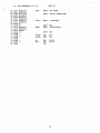
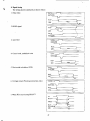
• Control as printer for MZ-80K
[Status check flow chart]
[Printing character transfer flow chart]
Start
Start
BUSY signal input
No
No
Transfers
chtacter code.
Makes DATA STB
signal low.
No
Normal
RETURN
31
RETURN
..
"~
01
02
03
04
05
06
07
08
09
10
11
12
13
14
15
16
17
18
19
20
21
22
23
24
25
26
27
28
29
30
31
•
180 ASSEMBLER SP-7101
0000
0000
0000
0000
0000
0000
0000
0000
0000
0000
0000
0000
0000
0000
000,1
0004
0007
0008
;; ; ;; ; ; ;; ; ; ;; ;; ;; ;; ;; ; ; ; ; ; ; ; ; ; ;
PRINTER CONTROL ROUTINE
••••• * •••••••• * •••••••••••••••••
I I
I
1 1
I 1 1
,
1 ,
1
,
1 1 1 ,
,
1 1 1 1 ,
1 1 I
,
1 • I
I
I
PRINT CONTROL
n;;;nnH;;;;;;;;;;;;;;;;;;;;;
ACC PRINT
PRINT:
F5
CDIDOO
CD6500
FI
C9
ENT
PUSH
CALL
CALL
POP
RET
AF
"PRNT
STCK
AF
0009
0009
0009
0009
0009
0009
0009
OOOA
0008
OOOC
OOOF
0010
0012
0014
32
33 0015
MESSAGE PRINT
DE=DATA LOW ADR
(END=CR CODEI
PMSGE:
F5
05
lA
CDIDOO
lA
FEOD
2S03
13
ISF4
34 0017 CD~500
35 OOIA DI
36 0018 FI
37 OOIC C9
3$ 0010
3~1
PAGE 01
O(l\['
40 00 I D
41 0010
42 00lE
p 0020
"
44 0023
45 0024
46 0026
47 00Z8
48 002A
F5
:3EOO
[:D2:300
FI
D3FF
3E80
D2-FE
2-EOl
49 002C CD2'2-0(l
50 OQ2F AF
ENT
PUSH
PM%I:
PMS(i2
~
PUSH
LD
CALL
LD
CP
JR
INC
,JR
CALL
POP
POP
RET
AF
DE
A, (DE I
"PRNT
A, (DE I
ODH
Z,PMSG2
DE
PM~:G I
STCK
DE
AF
PRINT
"PRNT:
PUSH
LD
CALL
POP
OUT
1.0
OUT
Lo
CALL
XOR
AF
A,OH
,BUSY CHECK
BUSY
AF
(POTFF), A
,DATA OUT
Af80H
(POTFEI,A
A,OlH
BUSY
A
32
,DATA STB HIGH
'BUSY CHECK
** zeo
01
02
03
04
05
06
07
ASSEMBLER gp-7101
10
11
12
0030 D3FE
0(1 ::z C9
0033
0(133
0033
0033 D~J
0034 57
0035 010000
00:::8 OBFE
003A E600
003C BA
0030 2002
P"
OO:-:F D9
08
O~I
14 0040
0041
16 0041
17 0043
18 0044
1 ~J 0046
20 0047
21 0048
22 0049
23 0048
24 004C
25 004F
26 0052
27 C,055
28 0058
2~1 0058
30 0058
31 0058
32 005B
33 005D
34 0060
35 0062
36 0063
37 0064
38 0065
PAGE 02
(POTFE),A
;DATA STB LOW
EX X
LD
LD
IN
AND
(:P
D,A
BC,OOOOH
A, (POTH)
ODH
D
,Ace-COMPARE DATA
'TIMER SET
JR
NZ,4
OUT
RET
BUSY
BI.lSY;
BUSY 1 :
CHECK
EXX
RET
C9
''15
lEl0
10
20FD
OB
78
Bl
20ED
D9
C00900
117DOO
CD1500
(::30(100
LD
DEe:
,JR
DEe
LD
JR
EXX
CALL
LD
NL
DE, MSGl
'~ALL
MSG
OR
,JP
E
E, 10H
E
NZ,-1
BC
A,S
C
NZ,BUSYl
ABNML
'ABNORMAL JUMP
STATUS INPUT
c:rt! DOO
STIN:
3EOO
CD3300
DBFE
OF
OF
C9
':PRNT
A,OH
BUSY
A, (POTFE)
STATUS CHECI(
39 0065
40 0065
41 0065 :<E07
42 0067 C05800
p
OObA 08
44 0068
45 006B 119FOO
46 006E CD0900
47 0071 C01500
48 0074 1 19500
49 0077 C[H500
50 007A C30000
CALL
LO
CALL
IN
RRCA
RRCA
RET
:::TCK:
STCK 1 ;
E
LD
CALL
RET.
LO
CALL
CALL
LD
CALL
JP
A,(l7H
;PAPER CHECK
STIN
C
'NORMAL RETLIRN
DE, MSC'2
NL
MSG
DE,MSG11
MSG
ABNML
33
;A8NORMAL JUMP
**
'-'
"''"-
01
, 02
03
04
05
06
07
08
09
10
11
12
13
14
15
It.
17
18
19
20
21
0070
0081
0085
0089
OOSO
0091
0095
0099
0090
009E
009F
OOA3
OOA7
OOAA
OOAB
OOM!
OOAB
OOAB
OOAB
OOAB
OOAB
Z80 ASSEMBLER SP-7101
4E4F20S0
4F574552
4F52204E
4F20434F
4E4E4543
54494F4E
28505249
4E544552
29
00
50415045
52204540
505459
00
MSO 1 ,
PAGE 03
DEFM
'NO POWER'
DEFI1
'OR NO CONNECT! ON'
I1S811'
OEFM
'(PRINTER) ,
MSG2'
DEFB
DEFM
OOH
'PAPER EMPTY'
DEFB
ODH
P
P
POTFF'
POTFE'
EQU
EQU
FFH
FEH
P
P
NU
MSG~
EQU
EQU
END
0OO9H
0015H
34
,ilk
•
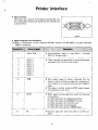
Printer interface
• Signal terminals
The printer has a total of 36 1(0 signal tenninals (Fig. 26).
The relationship between the signal and the tenninals are
as shown below.
, 1111!HllI111109S7"S"
Fig. 26
• Signal arrangement and description
(A) When a combination of host computer MZ-80B, interface card MZ-8BPSI, and signal cable MZ8BP4C is employed.
DATASTB
2
3
4
5
6
7
8
9
DATA
DATA
DATA
DATA
DATA
DATA
DATA
DATA
• Synchronization signal to read DATA I through
DATA 8. (Positive logic).
I
2
3
4
• These tenninals are signal lines to receive information
contained in the I st to 8th bits of data.
5
6
7
8
10
11
• Data request signal to infonn externally that the
printer is ready for data receiving after completion of
work related to the received data and code. (Negative
logic).
• This signal is output whenever BUSY signal changes
from high level to low level.
BUSY
~--------~-----------
12
PE
l
• BUSY signal becomes high level under the following
circumstances.
(a) When the printer is feeding and printing.
(b) When the printer is in DESELECT mode.
(C) When the printer is in FAULT state.
(d) When the printer is receiving data.
(e) When the printer receives PRIME signal.
-------
• Becomes high level when the printer is in PE condition.
35
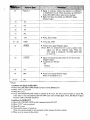
13
'SELECT
• Signal to indicate whether the printer is in SELECT
or DESELECT mode. When the printer is in SELECT
mode (ON-LINE mdoe), data can be received.
• High level when the printer is in SELECT mode.
(Positive logic)
14
OV
15
NC
16
OV
17
FG
18
+5V
• PULL UP at 330n
19 - 30
GND
• Twist pair, GND
31
PRIME
• Printer reset signal (Negative logic)
(Note) IRT for terminal No.34 is also a printer reset
signal, bu t has an opposite logic. When one
reset signal is employed, the other signal shall
be made NC.
32
FAULT
• Signal to indicate that the printer is in FAULT state.
(Negative logic)
• Conditions for FA UL T
• PE
• Dese1ect
33
av
34
IRT
35,36
NC
• Printer reset signal (Positive logic)
(Refer to terminal No.3I.)
• (Note)
Conditions for SELECT (ON-LINE)
• When ON-LINE/OFF-LINE switch is pressed during DESELECT.
• When "DC I " is received.
• When PE Occurs.
• If the ON-LINE/OFF-LINE switch is pressed in PE state, the select state emerges to cancel PE,
I-line data is read and printed, and then OFF-Line state emerges again. Then, the SELECT signal
becomes LOW. (Override function)
Conditions for DESELECT
• When ON-LINE/OFF-LINE switch is pressed during SELECT.
• When "DC3" code is received.
• When PE occurs.
• When power source is turned on.
(This state can be altered by the operation of the internal function switch.)
• When an error occurs in the printer.
36
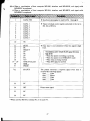
(B). When a combination of host computer MZ-80K, interface card MZ-BKP4I, and signal, cable
MZ-BKP4C is employed,
• When a combination of host computer MZ-80A, interface card MZ-8BP5I, and signal cable
MZ-8BP4C is employed.
DATA STB
• Synchronizationsignal to read DATA I through 8.
2
3
4
5
l;
7
8
9
DATA I
DATA 2
DATA 3
DATA 4
DATA 5
DATA 6
DATA 7
DATA 8
• These terminals receive signals contained in the I st to
8th bits of DATA.
10
NC
• Data input is not permitted when this signal is high
level.
13
14
15
16
17
18
19 - 29
30
31
*32
SELECT
OV
NC
OV
FG
+5V
GND (Twist pair)
GND
PRIME
STATUS
33
OV
34
IRT
35
NC
36
NC
(Conditions under which BUSY signal becomes
high level)
• When the printer is feeding or printing
• When the printer is in DESELECT mode
· When data are being received
• When I RT signal is received
The printer transmits a response signal every time it
receives the following signals.
05H ........ LOW
06H ........ HIGH
07H ........ LOW
08H ........ LOW
Printer reset signal
* When used for MZ-80A, terminal No.32 is made Ne.
37
I
•
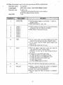
(C) When this machine is used by the Centronics System (ROM unit MZ-8S P4R)
Data input system:
8 bit parallel
Control signal:
ACK, BUSY, SELECT DATA STB, PRIME, FAULT
Data input code:
• ASCII code
(Setting of international characters is also possible.)
• 96O-byte image printing is possible.
I line
Data buffer:
s)J,i:r
.·.···t~r·.".,:I:ij'
. . . . . '. . . . .'. . ";i
............... ''-111'
.;
••.. .
. '.~
. '. . ~Ili
cr~.~;ii ...
' ....;;.].
). .• """'. i.'" . . .··f·..
.i .'.. ·."• ...•••.'.•.••.. .···.i!·
.'.........
. ...'i. ..•..•••
..... i')~ji'i':
:.i
1
,
I
DATA STB
Synchronization signal to read DATA I • (Negative
logic)
DATA 8.
• Pulse width shall be I Ilsec. min.
---
2
3
4
5
6
7
8
9
DATA I
DATA 2
DATA 3
DATA 4
DATA 5
DATA 6
DATA 7
DATA 8
•
•
These terminals are signal lines to receive information
contained in the I st to 8th bits of DATA.
Pulse width of data shall be 3 Ilsec.
._--
10
II
ACK
BUSY
be output when the printer finishes all its work
• To
related to received data and codes. (Negative logic)
be output whenever BUSY signal changes from
• To
high to low.
• Typical pulse width shall be 8 Ilsec.
When this signal is high level, codes other than DC
• code
shall not be input. (Positive logic)
•
(However, no input can be made during printing or
line feed.)
Conditions to make BUSY signal high .
(a) When the printer is feeding of printing.
(b) When the printer is 'in DESELECT mode.
(c) When the printer is in FAULT state.
(d) When data received.
(e) When PRIME signal is received.
._-
12
PE
13
'SELECT
• Becomes high level when the printer is in PE state.
to indicate whether the printer is in SELECT
• Signal
or DESELECT mode. (Positive logic)
can be input during SELECT.
• DATA
Becomes high level when the printer is in SELECT
• mode.
38
...
~,:-----------------------------------------------------------------------------------\,
14
OV
15
NC
16
OV
17
FG
18
+5V
• PULL UP at 3300
- 30
GND
• Provide.d for twist pair cable.
31
PRIME
• Printer reset signal (Negative logic)
(Note) IRT for terminal No.34 is also a printer reset
signal, but has an opposite logic. When one reset
signal is employed, the other signal shall be made
NC. Otherwise, trouble may be caused.
32
FAULT
• Signal to indicate that the printer is in FAULT
state. (Negative logic)
• Conditions for FAULT
I) PE
2) DESELECT
33
OV
34
IRT
35,36
NC
I~
• Printer reset signal.
• Refer to terminal No.31 PRIME.
'(Note) Conditions for SELECT
(a) When the ON-LlNE/OFF-LlNE switch is pressed during DESELECT.
(b) When DC I code is received.
(c) When the ON-LlNE/OFF-LlNE switch is pressed in PE state, SELECT mode will emerge to cancel
PE and read I-line data. After printing, OFF-LINE mode will be resumed. (Override function)
Conditions for DESELECT
• When the ON/OFF LINE switch is pressed during SELECT.
• When "DC3" code is received.
• When PE occurs.
• When power is turned ON.
(This state can be altered by the operation of the internal function switch.)
39
• I/O circuit conHguration
(I) DATAl - DATA8 (Input)
(2) DATA STB, DATA STB
+5V
+5V
560n.
560n
"
SN74LS244
(3) IRT (Input)
220n
I
SN75189
470PF
(4) PRIME (Input)
470n
>-------w.. . . -.----<lIO----~75189
12200PF
(5) BUSY, SELECT FAULT, ACK, PE, STATUS (Output)
+5V
~lKn
SN7406
40
.1"
• Signal timing
The timing charts (standard) are shown below.
\. Data input
DATA--...JI
DATA 5TS
~
BUSY
-ACK
2. BUSY signal
BUSY
-I ;
I-l0~s
(
'01
ACK
\
DATA
)
DATA STB
3. Line feed
t=
400,"5
DAT~
DATASTB
LJ
BUSY
I
ACK
70ms
-!
~
4. Cancel code, undefined code
DATA
DATA STB
t
BUSY
ACK
5. Horizontal tabulation (09H)
DATA
400}1s
r-
u-
r---r
DftTA 5TS
~
BUSY
ACK
6. Carriage return (Printing instruction code)
=t=
6,5ms
DAT~
DATA 5TB
BUSY
ACK
~
t=
7. When PE Occurs during SELECT
PE
SELECT ---,)'
FAULT - , / ,
BUSY
ON LINE SW
ACK
41
.
f
I(
'/
U
Character Code Table (ASCII)
The set of printing characters varies, depending on the kind of ROM unit used. Character Code Tables
for individual ROM units are shown below. Each table has a matrix structure, with the upper 4 bits of
hexadecimal ASCII code shown in columns and the lower 4 bits thereof shown in rows. For example,
the ASCII code for alphabet "A" is 41H .
• When ROM unit MZ-8BP4R is used
Character Code Table (For MZ-80B)
o
0000
o
0001
2
3
4
5
0010
0011
0100
0101
7
6
8
2
0010
3
0011
4
0100
5
0101
6
0110
7
0111
8
1000
[}£]
[l8[]
~
4 D T
% 5 E U
& 6 F V
7 G
u
~I~I
8 H X h X
9 IV[[]Y
•
• ~ z DJ
,• K
I
L.:...:.J L-=--.J
9
1001
A
1010
B
1011
C
1100
D
1101
E
1110
F
1111
,
A
B
C
D
1101
0000
0001
9
(
42
E
F
1111
• When ROM unit MZ-80AP4R is used
Character Code Table (For MZ-80A)
Upper 4 bits
0
Low.er 4 bit7" 0000
o
0000
1
0001
2
0010
3
0011
4
0100
5
0101
6
0110
7
0111
8
1000
9
1001
A
1010
B
1011
C
1100
o
1101
E
1110
F
1111
1
2
0001
0010
3
0011
4
5
6
0100
0101
0110
7
8
9
A
B
C
0
E
F
01' 1
1000
1001
1010
1011
1100
1101
111 0
1111
D [Q] l@] ~ ~ m[IJ LJ [9J [5J DJ [[3 B 0
0 DJ IT] ~ [gJ B [] EE ~ ~ D Cl E:g [tJ
0 0 [gJ [§J [BJ ~ [] D ~ ~ [ill ~ tij [] ~
la 00 @] [g ~ l*] ~ ~ ~ ~ ~ D 8J 8 [!]
III [!J @] [Q] IT] ~ ~ ~ El ~ Cd D D D D
Cl ~ [§J ~ [Q] ~ ~ D ~ [QJ EJ D IJ U l:.4iI
[EJ [YJ ~ ~ D rn DJ c:J El 0 ~ ~
III ~ [§]
~ [1J [§J ~ ~ CJ [ID § @] D U [] [0
•
•
[JJ [§J [8] [KJ [Q] ~ ~ lliJ [QJ co I- ~ [] ~
DJ ~ [lJ [YJ ~ ~ ~ [EJ [AJ ~ ~ ~ 0
~ D QJ ~ [] Cd lliJ [ill 0 0 ~ ~
DJ ITS] [bJ ~ [QJ EJ [8] ~ [ID CB G:l EJ ~
G W[g [S] KJ [8] ~ ~ [I]] f;J (] EJ 0 []]
EJ El [MJ [JJ KJ [2J 0 [EJ [ill [YJ [g ~ LSl []
GJ [}] [NJ fiE ~ [] [EJ @] [[] El] ~ [ZJ ~
[ZJ [1J [Q] El ~ [JJ ~ @] [] ~ ~ ~ 0 [m
m
rn
rn
43
ca
rn
,
• When ROM unit MZ-8KP4R is used
Character Code Table (For MZ-80K)
2
0
0000
0
0001
0010
3
4
0011
0100
5
0101
6
0110
3
0011
4
0100
5
0101
6
0110
7
0111
8
1000
9
1001
A
1010
B
1011
C
1100
D
1101
E
1110
F
1111
9
A
B
C
D
E
F
1001
1010
1011
1100
1101
1110
1111
I A
2 B
3 C
0001
0010
0111
8
n
00)0
2
7
4 D
E
7
8 H
9 I
•
•
~
,• K
,
(
L
7t
44
.
,
"
,
• When ROM unit MZ-8SP4R is used
As for characters marked" © "in the table below, different characters can be printed by the use
of the function switch. For details, refer to the Languagewise Character Table given below.
Character Code Table
~pper
4 bits
0
Lower 4 bit;- 0000
0
0000
1
0001
2
0010
1
2
3
4
5
6
7
8
9
A
B
C
0
E
F
0001
0010
0011
0100
0101
0110
0111
1000
1001
1010
1011
1100
'101
1110
1111
D [Q] @ [EJ @ [EJ
ITJ ITJ ~ [gJ ~ ~
0 [gJ ~ [ffi lliJ [[]
@ @] [g ~ [g] [i]
@ ~ [QJ IT] [ill W
~ ~ ~ [ill ~ ~
~ [§J [EJ [YJ [YJ
~ [IJ [§J ~ [ID ~
IT] ~ [8] 00 lliJ ~
DJ [ID DJ [Y1 IT] [tJ
~ 0 QJ ~ DJ ~
[±] [JJ [RJ @ [EJ @
Q IT] [Q @ ~
EJ El [MJ @ [iDJ 0
GJ [}] ~ @ [6] !@
LZl IT] [QJ 0 [QJ
3 '- 0011
!
i
4
0100
5
0101
6
0110
7
0111
8
loaD
9
1001
A
1010
B
1011
C
1100
0
1101
E
1110
F
1111
rn
rn
Languagewise Character Table
.
C!:f'
(2)
~j;
(t4~
Character code
40
5B
23
24
(Hexadecimal)
@!
$
ASCII standard
[
#
a
$
French
#_§
$
A
German
#
r- Danish
@!
$
#
I'E
Q
Swedish
#
E
A
..
@
$
#
Italian
@
$
Spanish
I
Pt
Note) Character codes 20H through 7EH are effeclIve.
7FH through FFH shall be ignored as character codes.
.
45
i
L
(c~;
(CS)
(tt,
(~
(Cg'l
@
ill
N
5C
5D
SE
60
7B
7C
7D
7E
I
I
I
-
\
1
l!
§
0
0
b
A
A
C
\
e
N
"
,
,
--,
,
,
0
---
e
u
'"
,
e
iI
e
a
6
ij
f.\
re
0
ii
6
u
a..
a
a
b
n
I
--
---
e
1
.'
Specifications
"i~'
Printing system
Feeding system
Maximum number of
printing characters
Kind of printing characters
Character dot construction
Interval between
characters
Graphic dot construction
'""i",,~("'
',::l:2:;;1;~J":),"··'" " _
--
Dot matrix impact system
• Tractor system
• Friction system
• 136 characters/line (ordinary character)
68 characters (enlarged character)
• 160 characters/line (ordinary character)
80 characters (enlarged character)
Differs depending on ROM units. For details, refer to the text.
Dot pitch
line changing pitch
Printing speed
Line changing speed
Quick return
9 (horizontal) x 8 (vertical), including half-dots.
• 10 characters/inch (in 136 character mode)
• 11.8 characters/inch (in I 6 ().character mode)
• 7 x 8 in 136-character mode
• 6 x 8 in 160-character mode
0.3628 mm (horizontal) x 0.37 mm (vertical)
1/6 inch, 1/9 inch (compression mode)
ISO characters/sec (in 16().character mode)
70ms
600ms
Prin ting direction
Bidirectional shortest-distance printing
Parts for replacement
• Head assembly • Cartridge ribbon
Printing recording paper
Cartridge ribbon
Refer to the specifications for printing recording paper.
Sharp cartridge ribbon (For MZ-80P4)
Signal color (Black)
• Color:
Nylon (plain weave)
• Material:
13
mm in width
• Dimension:
13 mm (endless)
• Length:
Other functions
• Graphic function (through the use of software).
• Form position memory backup function (through the use of
dry cells)
Applicable conditions
Relative humidity:
30%- 80%
Ambient temperature: SOC - 3SoC (operation)
O°C - 50°C (storage)
Local supply voltage (provided that it conforms to the specification on the rating indication plate.)
80W
S30mm
Width:
Depth:
464 mm (including the assistant gtlide)
Height:
178mm
15 kg
Rated voltage
Power consumption
External dimensions
Weight
..
• For Improvement of the product, part of the speclflcatIons and appearance may be changed WIthout
prior notice. Please understand that the description herein contained may be different from the
actual product in which improvement is made .
• This apparatus complies with requirements of EEC directive 76/889/EEC.
46
JI