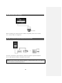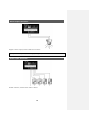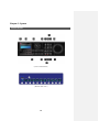
1
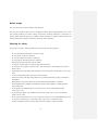
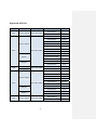
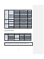
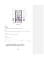
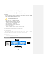
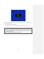
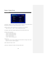
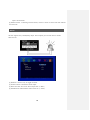
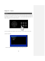
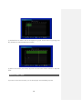
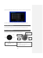
STANDALONE H.264
DIGITAL VIDEO RECORDER
User manual
Before usage
The User manual is for DVR installation and operation.
The user who install the device first or Qualified Personnal, before instllating DVR, has to read
user manual carefully and follow warning instrunctions avoiding malfunction of operation or
product failure. Refer all servicing to qualified service personnel or suppliers while install and set
the DVR. Keep these operation instructions handy for future reference.
Warning for safety
The user has to keep in mind of followings for safty usage and well-operation.
ㆍ Do not shock during installation or Product carried
ㆍ Do not expose to shock or vibration.
ㆍ Do not move while the product is operating.
ㆍ Do not plug out while the product is operating.
ㆍ After power off, clean the DVR only dry towel.
ㆍ Do not put out Plug code, touch power plug with wet hands.
ㆍ Do not place heavy object on power code, it may cause power code demage, occure fire or
electric shock
ㆍ Install stable place and keep proper tempeture, if install the DVR in sealed place, it may cause
a fire.
ㆍ Do not install humidty place, electronic hazard, moisture.
ㆍ Protect the power cord from being walked on or pinched particularly at plugs, convenience
receptables.
ㆍ Recommend to use protect device to prevent failure through blackout or lighting.
ㆍ Do not expose direct sunlight and install near radiators, heat registers or other apparatus
that produce heat.
ㆍ Do not place near flammable spray or any heat source, cause of flammable material,
it may cause a fire
ㆍ Do not demage, Blend, twist, modified, pull out, heat power code, it may cause demage
power code or outlet.
ㆍ Do not insert the metals such as a coin, a hair pin, a piece of iron or flammable Material such
as a paper, a matchstick, etc. in the DVR, It may cause a fire or an electric shock
ㆍ Contact to Supplier after turn off the DVR, when odor smoke or smell in the DVR,
2
Approved HDD list
Capacity
Manufacturer
HDD
Model
160G
Western Digital
HDD 160G SATA
F/W Ver.
WD1600AAJS
WD1600AAJS
22L7A0
WD2500AAJS
WD2500AVJS
63B6AO
WD2500AAKS
Western Digital
250G
HDD 250G SATA
WD2500AVVS
63L2BO
WD2500AVVS
73L2B0
WD2500AAJS
00L7AO
WD2500AAJS
22B4A0
HDS721025CLA382
Hitachi
HCS5C1025CLA382
HDS721025CLA382
Seagate
320G
Western Digital
Seagate
HDD 320G SATA
ST3250318AS
CC38
ST3250312CS
SC13
WD3200AVVS
63L2BO
ST3320418AS
CC38
WD5000AVVS63ZW80
Western Digital
500G
HDD 500G SATA
Seagate
Western Digital
00A7B2
WD5000AVVS
63H0B1
WD5000AVVS
63M8BO
WD5000AAKS
00V1A0
WD5000AVDS
63U7BO
ST3500418AS
CC38
ST3500312CS
SC13
HCS5C1050CLA382
Hitachi
750G
WD5000AAKS
HDS721050CLA362
HDD 750G SATA
3
WD7500AACS
WD7500AACS
HDD 1TB SATA
WD10EACS
HDD 1TB SATA
WD10EADS-00L5B1
HDD 1TB SATA
WD10EARS
00Y5B1
HDD 1TB SATA
WD10EADS
00L5B1
HDD 1TB SATA
ST31000528AS
CC38
HDD 1TB SATA
ST31000322CS
HDD 1TB SATA
HCS5C1010CLA382
HDD 1TB SATA
HDS721010CLA332
HDD 1.5TB SATA
ST31500341AS
HDD 1.5TB SATA
ST31500341AS
CC1N
HDD 1.5TB SATA
WD15EADS
00R6B0
HDD 1.5TB SATA
WD15EARS
00Z5B1
HDD 2TB SATA
WD20EARS
00S8B1
HDD 2TB SATA
WD20EARS
00Z5B1
Seagate
HDD 2TB SATA
ST32000542AS
Hitachi
HDD 2TB SATA
HDS722020CLA330
Western Digital
1TB
Seagate
Hitachi
Seagate
1.5TB
Western Digital
Western Digital
2TB
(February. 2011 )
Approved DVD-RW list
ODD
Manufacturer
DVD RW
Samsung Electronics
Samsung Electronics
ODD
DVD RW
LG Electronics
LG Electronics
LG Electronics
MODEL
F/W Ver.
SH-S203B
F/W : B
SH-S223Q
F/W : Q
GH22NP20
DVD-RW
GH24NS50
ROM VER : XP01
GH22NS50
ROM VER : TN02
(February. 2011)
[Waring] Please use approved HDD avoiding mailfuntion of operation, if the user want to
use other HDD, Please contact to supplier and check the HDD is available or not.
4
-
Contents
-
1. Overview
∙ Feature ……………………………………………………………………………………………………………………………………..……….8
∙ Application ………..………………………………………………………………………………….……………………..…………………….8
2. Installation
∙ Package contents ……………..……………………………………………………………………..………………………………………..9
∙ Rear panel ………..….……………….………………………………….…………………………….………………………………………..10
∙ Video Input ………………..…………………………………………………………………………...……………………………..………..11
∙ Loop out ………………………………………………………………………………………………..….…………………………………….11
∙ VGA output ………………….…………………………………………………….………………………………………………….………..11
∙ RS-485 connection (PTZ Camera) …………………………………….…………………………………………………...……….12
∙ RS-485 connection (External keyboard connection) ……………………………….……………………………..………12
∙ Alarm out connection …………………………………………………………………….………….…………….……………….…….13
∙ Sensor input connection ………………………….……………………….……………………….………………………….….…….13
∙ RJ-485 port (Internet connection) .………………………………………………………….……………………………..………14
∙ USB port …………………..……………………………………………………………………………….……………………………….…...14
∙ Call menu ………………………………………………………………………………………………….……………………………….…...14
3. System Operation
∙ Controll button ………….………………………………………………………………………………………….…..…………………….15
∙ Front LCD Icon …………………………….………………………………………………………………………………………………….18
∙ Front direction key ………………..………………………….…………………………………………….…………..……….…………19
∙ Mouse ………………………………………………….…………………………………………………….…………..……..…….....……….20
∙ Icon ………………...………………………………………..………………………………………………………………..………..…………..20
∙ Remote Controller ID Set-up ………………...…..…………………………………………………………………….……..………21
4. System Setup
∙ Information ……………………….…………………………………………………………………………………………..…………..…….23
∙ Time / Date ……………………………………………………….…………………………………………………………….……..…..…..24
∙ Password …………………..……………………………………..…………………………………………………………….…….……........25
∙ Hard Disk …………………....…………………………………………………………………………………………….…….…..…...……..26
∙ Defult set-up ………………….……….………………………………………………………………………….……………….….…...….27
∙ Up grade …………………..………………….……………………………………………………………………….………………..…….…27
∙ Button set-up …………………..…………………………………………………………………..……………..…………………….…….28
∙ Log out ………..………….………………………………………………………………………………………………….……………..…….29
5
∙ Serial Port set-up(RS-485) ……….………………………………………………………………...………………………..……..…..29
5. Display
∙ OSD …………………………………………………………………………......................................................................................…..30
∙ Split mode ……………………………………………………………………………………………………………………………..…...…..30
∙ Auto Sequance …………………..……………….………………………………………………………………………………..………...34
∙ Display control ………………….………………….………………………………………………………………………………..……….35
6. Network
∙ IP Address …………………….………………………….…………..…………………………………..……………………….…….………36
∙ Alarm alert set-up ………………………..………….…………..…………………………………..……………………….…….………37
7. Camera
∙ Camera set-up ……………………...……………………………………..……………………………………………..…….……….…….40
∙ Camera Title ……………………....………………..……..…………………………………………….……….…….……….…….……….41
∙ PTZ set-up ……………………..……..………………..……..…………………………………………….………….….…………..……….41
∙ How to use PTZ ………………………………………………………………………………………………………………………………42
8. Recording
∙ Recording ……………………...…………………………….………………………………………………….……………….….……..……47
∙ Schedule Recording ………………………………..……….….………………………………………….……………….……...………48
9. Event
∙ Sensor ……………………………………………………………….………………………………………………….…….…….….………….50
∙ Alarm ………………………………………….……………………….………………………………………………….…………...........……51
∙ Motion detection ……………………..……………………….……………………………………………………….………........……..52
∙ SPOT output ………………….………………………………….……………………………………………………….……………………53
∙ Audio output ………………….…..……….………………………………………………………………………….…...………..……..…54
10. Search
∙ Search …………………..………………………………………………………………………………………………………….……………...55
∙ Search by calendar ……………………….…………………..………………………………………………………………..……..……56
∙ Search by Date / Time ………….………………………………..………………………………………………………………………57
∙ Search by Event ………...………………………..…………………………………………………………………………………….….…58
∙ First serch / Last search …………………..…...…………..……………………………………………………………………….……59
∙ How to control Playback …………………......…………..…………………………………………………………………….………59
6
11. Back up …………………………………...……………………………………………………………………….……….……………...…61
12. Appendix
∙ Specification ……………..……………………….……….………………………………………………………………….............….…..63
∙ Product Warranty ………………………………………………………………………………………….….………..…………….…..…65
7
Chapter 1. Overview
Feature
The DVR employs H.264 video recording 4ch, 9ch, 16ch channel input and S-VHS and Spot out
put simultaneously. The DVR has mirroring function, mirroring HAD record and display regardless
of unexpected physical shock or demage.
Feature
ㆍControl Pan / Tilit by using Mouse or Joystick
ㆍ2 USB ports in front board for easy back-up
ㆍODD Back up available (Option)
ㆍFull Frame transfer under GIGA network available
ㆍMulti language
ㆍDynamic IP Internet access available
ㆍDual-Stream network transfer available
ㆍTV output, VGA output, S-VHS, Spot output available simultaneously
ㆍSupport D1 resolution each channel independently
ㆍSupport several PTZ protocol
ㆍCMS software
ㆍProvide software for Smart phone, IP viewer, Network Viewer
Application
√ Bank, ATM unit, Supermarket, Convenient store and other public places.
√ Private homes, Apartment, Jewelry shop, Commercial compound and other places
where it needs anti theft surveillance system.
√ Warehouse, Production line and other places where evidence is needed
after any event happened and to analyze the situation.
√ Where to monitor sites remotely
8
Chapter 2. Installation
Package contents
HDD screws (10 EA)
Software CD
Controller battery
Size : AAA
1.5V X 2EA
User manual
DIGITAL VIDEO RECORD
Adaptor
(12V 6A(SMPS)
Power code
Remote
controller
Package contants are consist of as followings.
√ Digital Video Record (1EA)
√ HDD screws
(10 EA)
√ Software CD (1EA)
√ User Manual (1EA)
√ Power code (1EA)
√ Remote Controller (1EA)
√ Controller Battery AAA (1.5V 2EA)
√ Adaptor (12V 6A 1EA)
[Note] Make sure Package contants when you purchse system.
Not included any package contants, Please contact to Supplier
9
Rear panel
It doesn’t need specific equipment to install DVR. Refer to each parts explaination in user manual.
(9 Channel rear panel)
(16 channel rear panel)
[1] Video input
[2] Video Loop out [3] Adaptor connector jack [4]
[5] RJ-45(For Network) [6] RS-485
[9] Serial Port (For Debugging)
[13] VGA output
[7] Alarm output
[10] Audio input
[14] Composite Monitor output
10
RS-485 Input
[8] Sensor input
[11] Audio output
[15] Spot out
[12] S-Video output
Video input
Connect Coaxial cable from Video source to BNC Video in connector.
Loop Out (Video source output)
Used to transfer a video signal to other video devices.
VGA Output
Use VGA input type of LCD monitor and CRT monitor.
11
RS-485 Connect (PTZ Camera)
PTZ Camera
Before connecting PTZ, check PTZ Protocol whether compatible protocol or not in DVR,
if it is, connect cables as configuration.
RS-485 Connection (External Keyboard Connection)
or
The DVR is controlled by specific keyboard , Pleasae ask supplier to purchase keyboard.
You can find Keyboard installation in keyboard user manual.
[Note] The user controls DVR through Keyboard or external devices such as PC, 99pcs of
DVR is controlled by provided DVR protocol.
12
Alarm output connection
Support 1 alarm output, connect cable same as above.
[Note] Provides simple On/Off switching by using relay
Sensor input connection
Provide 4 Sensors, connect sensor same as above.
13
RJ-45 Port (Internet connection)
Connect network through 10/100/1000Mb Ethernet connector.
Available remote surveillance and remote search by network between DVR and computer. .
USB port
Support 2 USB ports in the front panel, it uses for Firmware upgrade, Back up, Mouse.
Call menu
Available Menu set-up through Menu button in front panel, mouse and Remote controller.
Keep in mind of user manual to overall set up system.
∙ Call menu by “Menu” button.
Press “Menu” button in front panel.
(“ESC” button also use Call Menu function –“ESC” go to previous status.)
∙ Call menu by Remote controller
Press “SET UP” button in Remote Controller.
∙ Call menu by Mouse
Click Right button in the mouse, select desired menu in Pop-up menu.
14
Chapter 3. System
Control button
( Front control button )
( Mouse menu Icon )
15
(Remote button)
[1] SET UP
Call Menu
Goes to previous status in menu (Click Right button in Mouse).
[2] PTZ
Select desired channel to control PTZ camera, then press PTZ button to call PTZ menu.
[3] IR receiver
Receive the IR signal from remote controller.
[4] Search
Display recoding image.
[5] Split
Switch Full or Quad view, Max quad of screen according to DVR, Press direction button in
9ch, 16ch DVR
“▲” Press up button, change to different multi quad screen.
• 9 Channel DVR : Click “SPLIT” Button -> Revert to 9 quad mode
• 16 Channel DVR : Click “SPLIT” Button -> Revert to 16 quad mode
16
[6] Log out (Key lock function)
• To Log out, pressing “Lock” Button in front panel.
“Key lock” is same as “Log out” in mouse menu.
[7] Schedule Record
Start to record image according to setting schedule.
Press button to start schedule recording in emergency record mode.
[8] Emergency Record
In case of emergency, press “EMERGENCY” button to start recording forcibly regardless of the
recording schedule with setting resolution and recording frame in all channel.
Avoiding HDD waste, have to change to “Schedule recode” mode
[9] Audio
Select Audio Channel, can hear desired Audio.
[10] Sequence
Auto Sequence each channel will be conducted in Live according to setting dwell time between
camera. Set [MENU]-> [DISPLAY] -> [Auto Sequence] .
[11] Back up
Back up recording image.
[12] Channel / Numeric button
[13] Refer to “Front direction key”.
[14] LED indicator
Inform status of operation through lighting.
• IR : Turn LED off, receiving remote data.
• COMM : Turn LED off during communication..
• WARNNING : “Beep” sound and Turn LED off, when Error occure in HDD.
17
• LOCK : Turn LED on, Press “LOCK” button (Log out status).
• NETWORK : Turn LED on, remote access through internet.
• REC : 1) Turn LED on, recording image with schedule mode.
2) Turn LED off, recording image with emergency recording mode.
[15] Error list
In case of system error, the error icon appears on screen with beep sound. Press “ENTER”
button, stopping beep sound and display Error list.
Icon will be shown in the status bar.
• Main Disk 1 Error : 1st HDD error in HDD disk
• Mirror Disk Error : Mirror HDD error in HDD disk.
(Unless use mirror, revert to “Main Disk 2 Error”)
• DNS Connection Error : Dynamic IP file
• SMTP Connection Error : “E-mail notification” fail.
• Disk Full : HDD disk is full.
(Replace to HDD disk or setting “Overwrite” in Menu-Hard disk )
[16] Indicate function when select required Icon in Mouse menu.
[17] Split group setting
Split 4 mode in DVR-0800S and DVR-1600S, next group (5ch, 6ch, 7ch, 8ch) is changed
whenever press right direction button “▶” in front of panel or remote controller.
[18] Multi channel
Sequence sprit screen in live automatically.
Front LCD Icon
DVR ID
HDD1
HDD2
(HDD
Capability,
Temperture
IP address of DVR
18
HDD Icon
HDD operation
No HDD or Error
Front Direction Key
[1] Left Direction key
• Move left in Menu
• Used for backward or search fram in play
[2] Up Direction key
• Move up in Menu
• Multi Channel
[3]
Play / Pause / Confirm keky
• Confirm revised menu.
• Use to pause or resume the screen.
• Log-out (Press for a second)
• Inform Error list and “Beep” sound off (Only operate in Play)
[4] Right Direction key
• Move right in menu
• Used for quick forward search in Play
[5] Down direction key.
• Move down in menu
• Stop button in Play
• Status and Camera Title ON/OFF
19
Mirror status
Mouse
Most of DVR function can be controlled by mouse for PC users.
Select
Click right button in mouse to open main menu.
Click ◀ or ▶, to decide desired setting.
Call menu,
Move previous stage
PS/2 MOUSE
Icon
Indicate exist status in Live
HDD capability status
Network status
Emergency recording
Sensor status
Schedule recording
Motion detection
Key Lock status
Video loss status
Auto sequence
Record
Internet status
De-interlace
20
USB MOUSE
Remote controller ID set-up
DVR ID and Remote controller ID have to set same ID to control several DVR by using one
remote controller. (DVR ID is compatible with Keyboard (DCK-500A) )
[1] Check system ID then change setting
• MENU > System > Information > Remote ID
(Range : 0 ~ 99 )
To control several DVR by one remote controller, have to set remote ID each DVR separately.
(Factory defult “00”)
[Note] If set same ID in each DVRs, it may not set desired DVR by controller.
[2] Remote controller usage
Set same ID between remote control ID and desired DVR ID, if it is different between DVR
and remote controller ID, DVR doesn’t operate well by using remote controller.
21
Appear above screen pressing “ID” button of remote controller in live, press Controller No buttom
same as registered DVR ID.
• DVR ID=0 : Indicate exist DVR remote ID.
• “00” : Remote controller ID, press same DVR ID in controller No button and press “OK”
[Warning]
It has to be set same ID between DVR remote control “ID” and remote controller “ID”
If DVR isn’t controlled by remote controller properly, please check DVR remote “ID”
and Remote controller “ID”
When compatible with keyboard, it makes sure DVR ID.
22
Chapter 4. System Set up
Information
[1] Remote ID : Support ID remote controller, One remote controller can control several DVRs by
setting Remote controller ID according to DVR. (ID Default : 0, Max :99)
[2] Mouse sensitivity : Mouse sensitivity level can be adjusted at user’s convenience.
(Basic Level 1; Level 1 < Level 2 < Level 3 increasing reaction speed)
[3] Language : Support Multi language (English,Japanese,Russian,Italiano,Roman,Korean)
[4] Indicate version information.
• H/W Ver. : Indicate Haward Version
• S/W Ver : Indicate Software version
• N/W Ver : Indicate Network version
• UI Ver : Indicate UI version
• UI Date : Indicate UI developed date
[5] NTSC / PAL
Select NTSC or PAL as country and different frame and resolution according to NTSC or PAL.
(Resolution and frame is refered to Appendix. )
[6] Mac address: Mac address of DVR.
[7] Web Code : Identification for remote monitoring of Web browser.
23
Time / Date
[1] Time / Date : Set Time and Date.
[2] Date format : Select date format according to country.
• ASIA : YYYY/MM/DD --> 2006/05/31
• US
: MM/DD/YYYY --> 05/31/2006
• EURO : DD/MM/YYYY --> 31/05/2006
[3] Time server : It helps time set of DVR automatically by synchronization of time server service.
• Sync Cycle : Select the period to syncronize between DVR and time server.
• Time Server : Input the URL of server
• GMT : Select GMT time zone where user located in
[Note]
• GMT zone and time server name are searched easily on internet browser.
• In case DVR is not connected with internet or time server name is not collect, DVR
gives beep sound and error message. Press “CONFIRM” button to off sound and pop-up
a error message.
[4] Summer time set: Set Summer time “YES“, it is adjusted summer time according to desired
period in DVR.
24
Password
Set authority password according to user, Administrator (Admin) has all Authorities to manage all
function of DVR.
Authority is consist of “Configuration”, “Search”, ”PTZ setting”, ”Hard Disk”, ”Back up”,
”Record key”, ”Netowrk convert”
[1] User ID : it is consist of “Admin”, “User1~7“, “Admin” select all function automatically,
“User” can select desired function.
[2] Group : Specified authorites according to group type.
• Admin : Available all functions.
• Power User : Only available “Configuration”, “Search”, “Back-up”.
• User : Select desired functions.
[3] Password : Enter new password in selected ID. (Max. 8 Characters available)
[Note] Initial password is “11111111” with every ID.
[4] Function: Select authorites according to ID
[5] Network Convert: Select channel doesn’t display through network.
25
Hard Disk
It is HDD set up menu. It has to set carefully avoiding system error or malfunction of recording.
[1] Hard Disk1 : Set first Hard disk usage.
• Main Disk : Use first HDD
• Mirror Disk : Use Mirror HDD
• None : Not use
[2] Hard Disk2 : Set second Hard disk usage.
• Main Disk : Use second HDD
• Mirror Disk : Use Mirror HDD
• None : Not use
[3] Optical Disk Drive : Setting ODD for BackUp, Indicate “RW Write”.
[4] Erase : Format exist HDD disk.
[5] Total HDD capability: Indicate total HDD capability (Used HDD capability / available HDD
capability)
[6] Over-Write : When enable, HDD is overwrite the oldest existing recorded data once
the HAD is full.
[7] Auto Delete : Set the recording dates from 1~120days, previous date is delected automatically.
( Range : None use, set from 1 ~ 120days )
26
Default Setup
Set Factory defult except HDD disk, Language, Time, Network IP information.
Upgrade
The DVR is upgrade latest firmware easily whenever release new function and revert function. .
[1] USB : After copy the firmware in USB memory, insert USB memory in USB1 or USB2.
The system is re-boot automatically when the system is upgraded .
27
Copy firmware
USB Memory Stick
[Note] It may take 1 min ~ 1 min 30 second, Please wait till system rebooting.
Do not turn off power or remove USB stick while backup is being procedure.
It may cause failuar or malfunctioning of system.
[2] Configuration BACKUP : Back-up DVR configuration in USB memory.
[3] Configuration LOAD: Down load desired DVR configuration in other DVR .
Button Setup
Operation button (Front button, Mouse Button, Remote button), is for Auto key lock function and
Button Beep function.
[1] Auto Key Lock : It prohibits button use.
• ON : it lock function if it doesn’t enter desired password in limited time. It has to enter desired
password to use function again.
( Except, Select Channel, Split Image, Auto Sequence )
28
(Change to Lock Key mode.)
• OFF : Not use Auto Lock Key.
[2] Button Beep : Beep sound whenever pressing any key.
Lock out
Press
or “LOCK” for a second in live, it change to Lock out.
Serial Port Setup (RS-485)
Serial port set up is for other devices such as PTZ, Keyboard and so on.
[1] RS-485 port for “Keyboard”, “PTZ” and so on, the devices installation are different, have to
refer to the devices’s manual.
29
Chapter 5. Display
OSD
Set display status
[1] Alpha Blending : Set Menu transparancy.
[2] Camera Title : Indicate camera title.
[3] Status Bar : Indicate DVR status
(Status bar : indicate status Icons in bottom of screen)
[4] Multi Screen Border: Mark gray color Screen border line in screen.
Split Mode
Split screen 4 to 16 split screen, the user can decide desired split mode and desired channel.
[Note] Change to split mode pressing “MULTI CH” in front of DVR board in Live.
Channel Group is changed in sequence pressing “MULTI CH” button.
Select Split mode
Sprit 16 mode (16CH DVR)
30
• You select 16CH division mode and click “SPLIT” button to see 16CH display.
• If you want to change the channel number of selected window, click on mouse button or use
scroll bar
Sprit 13 mode (16CH DVR)
• You select 13CH division mode and click “SPLIT” button to see 13CH display.
• Change to Channel group pressing “SPRIT GRP” in Live.
(Adjust other split mode in the same way)
• If you want to change the channel number of selected window, click on mouse button or use
scroll bar
31
Sprit 10 mode (16CH DVR )
• You select 10CH division mode and click “SPLIT” button to see 10CH display.
• If you want to change the channel number of selected window, click on mouse button or use
scroll bar
Split 9 mode
• You select 9CH division mode and click “SPLIT” button to see 9CH display.
• If you want to change the channel number of selected window, click on mouse button or use
scroll bar.
32
Split 8 mode
• You select 8CH division mode and click “SPLIT” button to see 8CH display.
• If you want to change the channel, click on mouse button or scroll bar to change.
Split 6 mode
• You select 6CH division mode and click “SPLIT” button to see 6CH display.
• If you want to change the channel number of selected window, click on mouse button or use
scroll bar.
Split 4 mode
33
• You select 4CH division mode and click “SPLIT” button to see 4CH display.
• If you want to change the channel number of selected window, click on mouse button or use
scroll bar.
Auto Sequence
Auto Sequence is a function that switches video automatically by set time.
(*Once it is set, it operates by remote control or “SEQ” button on the DVR front.)
[1] Auto Loss Skip: This function skips channel with no video input..
[2] CH1 ~ CH8: Choose channel group (Channel can be different by model.)
[3] Dwell Time: Time can be set in auto sequence in order of channel. (Range: 1sec~30sec.)
34
Display Control
[1] Monitor: Icon setup menu
• Small: choose this in case you use small monitor
• NORMAL: choose this when you use normal monitor
• VGA: this is used when it is VGA or LCD monitor.
[Note]
서식 있음: 글꼴: 굵게
Choose small, Normal mode for CRT Monitor
서식 있음: 글꼴: 굵게
서식 있음: 글꼴: 굵게
서식 있음: 글꼴: 굵게
[2] VGA: VGA resolution setup
서식 있음: 글꼴: 굵게
• 800x600, 1024x768, 1280x1024
35
Chapter 6 — Network
IP Address
In order to set up the system or do monitoring from remote area, you have to set the network
system in DVR.
The user must know whether their internet is dynamic IP(DHCP) or static IP. Please check it to your
ISP before setup.
[Note] The difference between the dynamic and static IP!
• Dynamic IP: Internet line most of people are generally using and it is widely used. It does
not have fixed IP address which makes difficult to access from outside. People can access if
there is a server that gives the address separately. This unit supports Dynamic IP as separate
server is being operated.
• Static IP: It keeps specific IP in the internet line. As it has one and only address in the world
you can easily have an access.
[1] DHCP : If you are an Dynamic IP user, please set it to “ON”. If you are an Static IP user, please
set it to “OFF”.
[2] IP Address: Don’t need to enter address if you are a Dynamic IP user. But if you are a Static IP
36
user please input as the following example. If the network line is Static IP, please ask your
Internet Service Provider(ISP) for the information and input.
[Example]
• IP Address: 192.168.001.050
• Subnet Mask: 255.255.255.000
• Gateway: 192.168.001.001
• DNS Address: 168.126.063.001
[3] DDNS Address: This is a DDNS server address for Dynamic IP user. Please do not change.
The port is basically 3000.
• This has nothing to do with Static IP user.
• Factory default DDNS address is 115.068.007.022
[Note] If dynamic IP user uses the router, the user should do the port forwarding, Please
consult the manual of the router for port forwarding..
[4] The bandwidth can be selectable as the network speed for smooth image streaming..
• High: it transmits current video quality.
• Middle: It transmits in middle level from current video quality.
• Low: It transmits in low level from current video quality.
☞ 3 different level of Bandwidth can be additionally adjustable.
[5] Additional Transmission Mode
• Use: Max 120fps can be transmitted through the internet
• Non-use: Max 480fps can be transmitted through the network..
Alarm Alert Set-up
When event occurs or there is a change in the system setup, it will send those information to
registered address in the unit.
E-mail Setup
Please be cautious of setting If the setup is wrong, It may not send you any alert emails.
37
• Mail Server (SMTP SERVER): Mail sending server. Input the mail server address of user.
Input the send mail(SMTP) address. If you are not sure, please contact your mail server manager.
• PORT: Most mail server use port 25 so, if it doesn‘t work, please check the port No.
• Mail(E-Mail) Address: Input the e-mail address of receiver (Max. 4 people)
• Password: Set it whether to use or not.
√ On / Off: Set to “Off” for sending mails without certification. Set it to “ON” in case you
need password and input the followings.
√ If you set it to “Off”, user ID, password should be input.
Alert Alarm Types
38
Choose when to send an email.
• Mail: When sending email, the email with this title will be sent.
• Interval: If you make the time setup in event cases, the DVR doesn’t send the e-mail repeatedly
during the selected duration. It is to prohibit the mass e-mail sending in frequent events
• Sensor: An email will be sent when sensor input is triggered.
• Motion Detection: An email will be sent when motion is detected.
• Video Loss: It sends an email when video input is disconnected.
• Power On: It sends an email when power is input to the system.
• Password Modify: An notification email will be sent when system password is changed.
• HDD ERROR: An notification email will be sent when when HDD error is found.
39
Chapter 7 — Camera
Camera Setup
You can set up the usage of camera and color setting.
[1] Channel: Choose a channel to set up.
[2] Covert: It hides the video if you set to “On”.
• On: Use
• Off: Not use
[3] AGC (Automatic Gain Control): It prevents too much strong signal controling Gain and it helps
with proper brightness in accordance with camera output signal.
[4] Static Gain: This amplifies camera input signal according to the Gain..
If the video is displayed dimly, it increases Gain, if the video is displayed brightly, this will
decrease the Gain for right amount of Gain.
[5] Brightness: controls brightness and darkness.
[6] Contrast: controls contrast of black and white of video
[7] Hue: level of color or hue.
40
Camera Title
Input Camera name.
If you click on channel, input panel will pop up.
PTZ Set-up
In this menu, you can set up about PTZ camera.
You should set whether or not to use Pan/ Tilt Camera and protocol. (Default is D-Max Protocol)
• Channel: Select a channel to connect.
• Serial Port: Choose RS-485.
• Model: Select PTZ model.
• ID: Select Pan/ Tilt ID. (Refer to the instruction manual of Pan/ Tilt manufacturer.)
41
Advanced
PTZ detailed setup is applied some specific models.
[1] Pan Speed: Movement speed of right and left.
[2] Tilt Speed: Movement speed of up and down.
[3] Zoom Speed: Speed control of zoom
[4] Focus Speed: Speed control of focus
[5] Reverse Control(Pan): If you set to on, it will move to reverse direction of right and left.
[6] Reverse Control(Tilt): When you move it up or down, it moves to opposite direction.
[Note] Select PTZ protocol
Protocol is PTZ moving driver. The protocol is registered as camera model name or
protocol name. Please check whether your PTZ is usable for this DVR
How to use PTZ
How to call PTZ menu
Before you use this function, camera must have been installed and DVR setup must have been set.
(1) Calling Menu from DVR Front: Select the channel that is connected to PTZ. Press PTZ button
and
“+” sign will appear.
42
(2) Calling Menu using Mouse: Select channel that is connected to PTZ camera and click on right
button of mouse. Then click on PTZ icon. “+” sign will show up.
(3) Calling Menu from Remote Control: Select channel that is connected to PTZ. Then press “PTZ”
button on the remote control. “+” will show up on the screen afterwards.
43
(PTZ Control View)
How to operate PTZ
(1) Operating from Front key
P/T, Z, F
• Operate the PTZ by using direction keys as above.
• Whenever you press “confirm”(Enter) key, menu changes and operate using left or right key.
- P/T: Move PTZ camera
- Z: Zoom in or out
- F : Focus control
(2) Operating by Mouse
44
•When you use mouse, drag the mouse from inside to outside. If the mouse is moving farther
away from center, the speed becomes faster.
• Whenever you turn the mouse scroll, menu changes and control by moving to left/ right
direction.
- P/T: Move Camera
- Z: Zoom in /out camera
- F: Adjust Focus
(3) Operating by Remote Control
• The camera can be moved by direction key.
• By pressing the ‘enter’ key, the menu changes then, select right/left.
- P/T: Move camera
- Z: Camera Zoom In/ Out
- F: Adjust Focus
Advanced Pan/ Tilt Menu
45
After you call Pan/ Tilt menu, click it on once again. Then advanced menu will show up.
(1) In front button or in remote controller, if you want to change the pop-up location of advanced
menu, move to right/left. (If you use mouse, you can drag it.)
(2) Choose wheter to let “+” sign appear on the screen or not.
(3) If you choose Pan/ Tilt mode, camera can be moved.
(4) It converts to enlargement/ reduction mode of PTZ.
(5) It converts to camera focus mode.
(Articles 3, 4, 5 above can be converted by confirm (Enter) key without calling advanced menu.)
(6) Auto Focus.
(7) Save preset number.
(8) Select preset number to save.
(9) Camera moves to appointed preset number.
(10) You can change the PTZ camera channel.
(11) It tours all preset numbers in order of storage.
(12) It calls PTZ camera menu from the PTZ camera itself.
(13) It ends the PTZ mode. (or press “Menu” key several times.)
46
Chapter 8 — Recording
Recording
Set up recording resolution, frame and quality of each channel. Please be catuious when setting
up as it records according to the set size or quality of image.
[1] Pre-Recording
If you set it to “ON”, you can let the DVR start recording about 5 seconds in advance of event.
[2] Channel: Select a channel to set. (if you want to apply to all channels, choose “All Channel”.)
[3] On / Off: Choose a channel you want to apply. If you set it to “ON”, it will not record at all
even though cameras are connected.
[4] Resolution: Set recording resolution.
[5] Speed: Choose frames to record.
[6] Quality: Select recording video quality.
[Quality] HIGHEST > HIGH > NORMAL > LOW > LOWEST
[7] Post-Recording: Set the duration time after event is finished.
[8] Record Audio: Select a channel for audio recording.
47
Schedule Recording
It is a function that reserves recording by day, time and channel. You can set it by an hour.
None: does not record
Continue: always record
Motion: it records when motion is detected.
Sensor: it records when sensor is detected
Motion + Sensor: it records either sensor or motion is detected.
[How to set]
[1] Select a channel.
[2] Choose day/ time and the event color will change every time you press “Confirm” key.
[3] Whenever you choose another day or time and press “Confirm” key, event color behind the
48
current location will change.
[4] Delete: It deletes selected schedule of the day.
[5] Copy channel: It copies the current recording schedule to designated channel.
[6] Copy all channel: It copies all current schedule of the week to all channels.
[7] Holiday(H): Holiday is all different by country. So you should separately set.
You can set holidays like above image. Please click on “H” first and calendar will pop up.
Using direction key, move to a number you want to set for holiday and press “Confirm”(Enter) key.
Then it will be highlighted in red color. Once you set your country holidays, all of them will be
recorded as you set.
[Note] When using a mouse,
If you use a mouse, you may want to choose event (■N
and drag to the day you want, whch is easier way to set.
49
■C ■M ■S
■M+S) first
Chapter 9
— Event
Sensor
You will learn how to connect sensor and set. The unit supports 4 sensor inputs regardless of
model.
* Connecting camera might appear differently by 9/ 16Channel.
[1] Sensor Input : Select channel for sensor input.
[2] On / Off : If you want to use the sensor, set it to ‘On’, or ‘Off’.
[3] Input Type : Select a type of contact point.
• N/Open (NORMAL OPEN) : It is normally open but the alarm will go off when the sensor
input is connected.
• N/Close (NORMAL CLOSE) : It is normally closed but the alarm will go off when the sensor
50
input is disconnected.
[4] Related Camera : Connecting with the sensors, choose a camera to record and multi cameras
can be chosen.
Alarm
This unit supports only 1 alarm(Relay) output. In this chapter, you can learn how to connect
Alarm and set.
[1] Detection : Choose a way to trigger the alarm.
[2] Channel: Choose a channel for alarm output.
[3] Alarm Out Time: You can set alarm output time. (1~30sec.)
[4] Internal Buzzer: Internal Buzzer Time can be set. ( 1~30sec.)
51
Motion Detection
It is a menu that you can set up motion detection menu. In this function, you can set area and
sensitivity when motion is detected on the image.
[1] Channel: Select a channel to set Motion Detection
[2] On / Off: Choose On or Off whether you will use the function or not.
[3] Sensitivity: Set up the sensitivity. ( 1~10sec.)
( *Before applying sensitivity, check out reaction to the sensitivity.)
[4] Detection Area: Set up area you want
Use Up/ Down/ Left/ Right key to set. Press “Enter” to select.
• Selected motion area: borders in blue
52
• Unselected motion area: nothing appear (transparent)
• Motioned detected area will be shown in red color.
[Apply to all] You can easily select or unselect all areas using one key.
Button “1”: Select All
Button “2”: Release All
[Using Mouse]
Place the pointer on starting point. With the right button pressed, drag to ending
point and release.
SPOT Output
Using extra monitor, you can observe better. ‘Spot Output’ will automatically show each video
channel in sequence. You can give each video channel time or particular channel will pop up on
event..
[1] Display Time: Select the output mode.
* If you set it to any channel fixed, the selected channel will be displayed at all times.
• Sequence: videos will be displayed in sequence of channel number.
• Event: channels with event outbreak only will be displayed.
• Seq + Event: it displays videos in sequence of channel number but if event occurs, event
channel will preferentially pop up.
[2] Time: Dwell time between channels can be set.
53
Audio Output
If the microphone is connected to the DVR on site, you can listen to the audio sound in live or
search mode. The audio listening is possiblei in muti-screen mode as well.
[1] Menu Call: If you select the “AUDIO” during the live or search mode, the audio output menu
show up. The menu call is possible from the front key, remote control and mouse.
[2] Select Mode
• Off: No Audio output.
• CH1: Audio Output from CH1 only
• CH2: Audio Output from CH2 only
• CH3: Audio Output from CH3 only
• CH4: Audio Output from CH1 only
• Auto: Audio Outputs from selected channels only
54
Chapter 10 — Search
Search
The unit can record for a long time but also you can easily search video clips you are looking for
by adjusting some conditions. So you don’t have to sit on a chair all day long to find videos you
want. Search can be made by time, motion, sensor etc. These methods will be often used. So it
will be convenient for you if you learn it by heart.
[1] How to call Menu: Press “SEARCH” button on the front or remote control or mouse menu.
[2] Select Search Mode
• Search by Calendar: You can use this search if you don’t know exact time.
55
• Search by Date/ Time: You want to use this when you know the time..
• Search by Event: This mode is used to find the recorded image by event.
• First Search: The first data recorded in the hard disk will play.
• Last Search: The last data recorded in the hard disk will play.
Search by Calendar
It searches by calendar and multiple videos will be displayed when you use this calendar search.
[1] If you confirm calendar search, when DVR brings the recorded information, calendar will be
shown. If you see numbers in red, it means there are recorded datas on the red-colored date.
You can change year/ month/ day by using direction key..
[2] Recorded data by time/ channel on the relevant date will be shown up in graphs. Select time
and press enter. (Channels are displayed differently by model.)
56
[3] Recorded data of relevant time will be displayed in graphs. Choose minute .by pressing enter
key. (Channels are indicated differently by model.)
[4] Based on the chosen year/ month/ day/ time so far, the screen will be converted to ‘Play back’
mode.
Search by Date / Time
If you know of exact date and time, you can directly input and immediately play back..
57
[1] Start Recording: From recorded data, it indicates first time.
[2] End Recording: From recorded data, it indicates ending time.
[3] Channel: Select a channel to play back or all channels.
[4] Play Begin: Choose date/ hour/ minute.
[5] Play: It plays back according to selected date.
Search by Event
It helps you find the recorded data by event from the selected date.
[1] Date: Input date you want to search.
[2] Channel: Select channel you want to look up. (Channel display is different by model.)
[3] Event: Choose event type you want.
58
[4] Search: If everything (date, channel, event type) is chosen, start searching in these conditions.
[5] As above image, if you click on anything from above, it will immediately play back.
First Search / Last Search
From recorded date in HDD, the first or last recorded data can immediately play back.
How to control playback
The followings are explanation of useful functions during playback.
Playback in normal
direction
Reverse Playback
Jog
Shuttle
①
Reverse Playback or Pause
②
Reverse Playback or speed of it.
dial
Jog dial: Search in normal/ playback, reverse playback mode
on freeze frame.
③
Playback speed.
Shuttle: Playback in normal / reverse direction
④
Stop
(If you turn shuttle, screen will be frozen and playback speed
will change to x1, x2, x4, x8, x Max)
59
[Controlling from Front panel]
[Controlling Jog-shuttle]
[Using Mouse]
[1] Reverse to 5mins back and play
[2] Speed control of reverse playback
[3] Playback in normal direction
[4] Stop
[5] Pause
[6] Playback
[7] Speed Control of Playback
[8] Move 5mins forward and play
[9] Change devision mode
[10] Change division group
[11] Listening to Audio
[12] Change De-interace mode
※ De-interlace: When you play back recorded image in 704X480 size, if the fast-moving
picture is trembling, de-interlace mode will compensate.
60
Chapter 11 — Back-up
Back-up
After you select requested data, you can save it in external equipment (USB or ODD). When the
data is saved, viewer program will automatically be saved. So you can conveniently view the backup data anywhere.
(1) Connect back-up device (USB / ODD) to the DVR.
(Insert empty disk in case of ODD.)
(2) If you press “BACKUP” button, the following menu will pop up.
* Channels indication are different by model.
(3) Select “USB” or “CD/ DVD” from back-up device.
(4) Input back-up starting time and ending time.
(5) Channel Select: Select channels to back up. (Selected channels are indicated in red.)
(6) If the setup is done, press “Backup start”..
61
(7) If back-up is properly done, you will see a file as below in USB memory stick and it will play
video clip if you click on it..
(8) How to use Viewer program. (it will automatically run when you click on backup video file.)
① Scroll Bar: It indicates where you are located in the whole data.
② Open: It is used to see another backup file.
③ Reverse playback
④ Fast Reverse Playback
⑤ Play backwards frame by frame
⑥ Pause
⑦ Play forward frame by frame
⑧ Play
⑨ Fast play forward
⑩ Quad view
⑪ Split into 9 screens
⑫ Split into 16 screens
⑬ Capture the current image
⑭ It is used to convert into AVI file. If you click on any part from “Start” and “End” section
respectively, time will automatically be input. Then if you click on “AVI” key, it will be converted.
⑮ If you click on any number, you can listen to sound of relevant channel.
62
Chapter 12 — Appendix
SPECIFICATION
Screen Display
9CH
16CH
Operating System
Embedded Linux
Compression
H.264
Audio Algorithm
G723.1
Video System
NTSC / PAL
Input
Video
In/output
9Ch
16Ch
Output
Loop Out (4/9/16 ), Composite (1), Spot(1), S-VHS(1) VGA(1)
Mode
Compact TV, CCTV, VGA Monitor
Live
Real Time Live
Split Screen
1, 4, 6, 8, 9
1, 4, 6, 8, 9, 10, 13, 16
Recording
NTSC
CIF( 352 X 240 ), 2CIF(704 X 240), D1(704 X 480)
Resolution
PAL
CIF( 352 X 288 ), 2CIF(704 X 288), D1(704 X 576)
Recording
Frame
CIF
270 / 225 fps
480 / 400 fps
2CIF
240 / 200 fps
240 / 200 fps
D1
120 / 100 fps
120 / 100 fps
Recording Mode
Search
Audio
Emergency, Schedule, Sensor, Motion, Sensor+Motion,
Pre&Post Event
Mode
Calendar, Date&Time, Event, Start, End
Speed
x1, x2, x4, x8, xMax (by minute; 1min, 2mins,3mins …)
In/Output
4/1
Volume
Volume Adjustable
Sensor input/ Alarm Out
PORT
4/1
RS-232
Keyboard control
RS-485
PTZ Control
LAN
10/100/1000 Base-Tx Ethernet (RJ-45) - Fixed IP, DHCP & DDNS
Network Control
Video Dual-Stream ( Local recording & Network Transmission)
Remote
Software
CMS, Network Viewer, IP Viewer, Smartphone App.
Access
IE
Web Site Monitoring ( http://www.livesecu.com )
Internal
Backup
Device
External
ODD BACKUP (OPTION)
Local Backup by USB Memory Stick & Network Backup by Network
Viewer, CMS
HDD
( 2 x SATA HDD)
63
ODD
DVD-RW (optional)
System Operation
Front Keys, USB Mouse, IR Remote Control, Keyboard (Optional)
Multi Language supported
When inputting camera name, Korean’s available.
Other Functions
Pan/ Tilt are controlled to Mouse’s direction
During backup, Viewer program is automatically saved and the files
can bbe converted to AVI
Power
DC 12V 6A
Operating Temperature
0℃ ~ 40℃
Dimension
428 mm(W) X 88mm(H) X 420mm(D)
Weight
5.2Kg
64
Product Warranty
This unit has thoroughly been tested and passed on quality control& quality assurance. Based
on the warranty, If this unit malfunctions during normal use, you will be guaranteed to get your
item repaired free of charge under joint agreement based on thee warranty.
[Tips on warranty].
■ Check out the Warranty first.
■ Check the item again what is wrong with it and contact the seller of this unit.
[Warranty details]
■ In only case the unit malfunctions during normal operation, the unit can be repaired
for free but within a year from the date of your purchase.
■ Repair cost and service charge will be requested in the following cases,.
1. Failure or damage incurred by user.
2. Failure or damage incurred by natural disaster.
3. Failure incurred by user who doesn’t abide by the operation manual..
4. Problem incurred In case appointed power supply (voltage, frequency) is not used..
5. In case user requests consumable parts.
6. In case nontechnical expert changes contents of the unit or damages.
■ Failure of goods out of warranty(1year) can not be fixed for free but it will be repaired
if you are willing to pay for the parts or service..
Product Warranty
Item Number
Serial Number
Purchasing place
Date of Purchase
Warranty period
Name
Customer
Address
▷ This Warranty can’t be reissued.
▷ When purchasing this unit, please let the seller fill in the blanks above.
▷ If you want to get your items repaired for free, please hand this over.
65
■ For safe use of system and to prevent product failure or accident, please read this manual carefully before use.
■ The manual includes the product warranty.
Be sure to keep it handy for later reference.
66