1
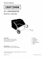
Owner's
Manuat
®
LAWNSWEEPER
ModeJ No°s, 486.24221
CAUTION:
•
•
•
•
•
Before using this product, read this
manuaU and follow aH Safety RuUes
and Operating Instructions.
Safety
AssembLy
Operation
Maintenance
Parts
mMPORTANT:
For Missing Parts or
AssembUy Questions Call 1-866-576-8388
Sears, Roebuck
and Co., Hoffman
Estates,
IL 60179 U.S.A.
www=sears=com/craftsman
PRINTED IN U.S.A.
FORM NO. 49994 (12/05)
ONE YEAR FULL WARRANTY
When assembled, operated and maintained according to the supplied instructions, if this Craftsman Lawnsweeper fails due to a
defect in material or workmanship within one year from the date of purchase, cal! 1-800-4-MyoHOME to arrange for free repair (or
replacement if repair proves impossible).
This warranty is void if this product is ever used for commercial or rental purposes.
This warranty applies only while this product is used in the United States.
This warranty gives you specific legal rights, and you may also have other rights which vary from state to state.
Sears, Roebuck and Co., Dept. 817WA, Hoffman Estates, IL 60179
Any power equipment can cause inju ry if operated improperly or if the user does not understand how to operate the equipment.
Exercise caution at all times, when using power equipment.
1. Read the vehicle and sweeper owners manuals and
know how to operate your vehicle and sweeper before
using this sweeper attachment. Always instruct other
users before they operate the sweeper.
2. Do not permit children to operate sweeper.
3. Do not permit anyone to ride on sweeper.
4. Never attach the hopper rope to any part of your body
or clothing! Never hold onto the rope while towing the
sweeper! Attach the rope to the towing vehicle to keep
it away from wheels and rotating parts.
5. Operate the sweeper at reduced speed on rough
terrain, near ditches and on hillsides to prevent loss of
control.
6. Vehicle braking and stability may be affected with
the attachment of this sweeper. Do not fill sweeper
to maximum capacity without checking the capability
of the towing vehicle to safely pul! and stop with the
sweeper attached. Stay off of steep slopes.
7. Stop and inspect vehicle and sweeper for damage
after striking an object. Repair any damage before
continuing operation.
8. Keep sweeper away from fire. Excessive heat can
damage the brushes and hopper bag and could cause
the bag and its contents to burn.
9. Before storing the sweeper, always empty the hopper
bag to avoid spontaneous combustion.
10. Follow maintenance and lubrication instructions as
outlined in the maintenance section of this manual.
Look for this
symbol
point isout
important safety precautions. It means -- Attention!!
Become
alert!!
Yourtosafety
involved.
The mode! and serial numbers will be found on a decal
attached to the lawnsweeper.
MODEL NUMBER:
You should record both the serial number and the date of
purchase and keep in a safe place for future reference.
DATE OF PURCHASE:
SERIAL NUMBER:
486.24221
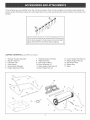
Theseaccessories
wereavailablewhentheunitwaspurchased,
TheyarealsoavailableatmostSearsretailoutletsand
servicecenters,MostSearsstorescanorderrepairpartsforyouwhenyouprovidethemodelnumbersofyourtractorand
sweeper
tothelawnsweeperto helploosenandremovedead
TheFront
MountDfromthelawnwhilesweeping.
ethatcheD
Mode!486.24219
attaches
grassandthatch
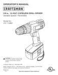
CARTONCONTENTS(LoosePartsin Carton)
1.
2.
3.
4.
5.
6.
SweeperHousingAssembly
BagArmTube(2)
LeftHitchTube
HitchBracket
HitchBracket(Straight)
HeightAdjustment
Strap
7. HeightAdjustment
Handle
8. RightHitchTube
9. RearSupportBrace
10,BrushAssembly
(2)
11.UpperHopperSideTube(2)
12.RearHopperTube(2)
13,LowerHopperSideTube(2)
14,HopperSupportRod(2)
15.BagFrameStrap
16.HopperBag
17.Rope
12
11
%\
10
13
13
14
16
\
/
9
/
2
SHOWN
FULL SIZE
T
J
NOT SHOWN
FULL SIZE
7BB
REF.
QTY.
A
B
C
D
E
F
G
H
I
J
K
L
M
N
O
2
2
2
4
1
2
4
2
6
10
2
2
2
2
2
DESCRIPTION
Hex Bolt, 5/16 x 2ol/2" Lg.
Hex Bolt, 5/16 x 2" Lg.
Curved Head Bolt, 5/16" x 1o5/8"
Carriage Bolt, 5/16" x 1ol/2"
Carriage Bolt, 5/16 x 1" Lg.
Hex Bolt, 5/16" x 3/4"
Hex Bolt, 1/4" x 1"
Hex Bolt, 1/4" x 1/2"
Ny!ock Nut, 1/4"
Nylock Nut, 5/16"
Hex Nut (Plain), 5/16"
Flat Washer, 5/16" (Small)
Flat Washer, 5/16" Std. Wrt.
Lock Washer, 5/16"
Bowed Washer
REF.
QTY.
P
Q
R
S
T
U
V
W
X
Y
Z
AA
BB
CC
DD
1
1
8
2
2
2
2
1
2
2
1
1
1
4
1
DESCRIPTION
Lock Washer (Tooth), 5/16"
Hair Cotter Pin, 1/8"
Hair Cotter Pin, 3/32"
Clevis Pin, 3/8" x 1/2"
Clevis Pin, 1/4" x 1ol/8"
Clevis Pin, 1/4" x 1o3/4"
Clevis Pin, 3/8" x 3"
Spacer Bushing,
Hitch Spacer, 3/4"
Vinyl Cap
Grip
Knob, Plastic
Hitch Pin
Plastic Plug
Angle Bracket
°1
TOOLS
REQUIRED
FOR ASSEMBLY
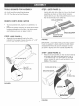
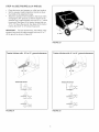
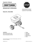
STEP 2: (SEE FIGURE 2)
, Each brush assembly has one brush retainer
marked with either red or black ink, Lay out the brush
assemblies as shown so that the brush retainers
marked with ink are in the middle with the red one on
the right and the black one on the left,
(2) 7/16" Open End or Box End Wrenches
(2) 1/2" Open End or Box End Wrenches
REMOVE
OVERLAP
PARTS FROM CARTON
BR{STLES
To protect painted parts, lay them on cardboard or a
mat,
Remove the sweeper housing, the loose parts and the
hardware package from the carton, Lay out the parts
and hardware as shown on pages 3 and 4,
BRUSH
MARKED
BRUSH
STEP 1: (SEE FmGURE 1)
, Assemble the roar support brace to the holes
indicated in the sweeper housing, Use two 1/4" x 1/2"
hex bolts (H) and 1/4" nylock nuts (I),
MARKED
RETAmNER
RED
RETAmNER
BLACK
FIGURE 2
IMPORTANT: The overlap bristles at the bottom of each
brush help support the back side of the brush for better
sweeper performance, Be sure the sweeper is turned
as shown in figures 2 and 3 to correctly assemble the
brushes,
STEP 3: (SEE FIGURE 3)
, Attach the brush assembly with the red brush retainer
to the right end of the brush shaft using two 1/4" x
1" hex bolts (G) and 1/4" nylock nuts (I), The brush
retainer marked with red ink must be placed to the
middle of the sweeper,
I_"NYLOCK
BRUSH
NUT(0
-'---_
RETAmNER
MARKED
RED
1/4" x 1"
HEX BOLT (G)
FIGURE 1
FIGURE
5
3
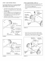
STEP 4: (SEE FIGURE
,
4}
STEP 6: (SEE FIGURE
Attach the brush assembly with the black brush
retainer to the left end of the brush shaft using two
1/4" x 1" hex bolts (G) and 1/4" nylock nuts (I). The
brush retainer marked with black ink must be placed
to the middle of the sweeper.
Turn a wheel to rotate the brushes. (The wheels drive
the brushes in one direction only.) The overlap bristles
should be on the back side of the brush as it rotates.
,
6 AND 7)
Cut off the plastic tie that holds the height adjustment
tube in place.
Assemble the right hitch tube (stamped 06R) to the
sweeper housing using two 5/16" x 1-1/2" carriage
bolts (D), and two 5/16" nylock nuts (J). Do not tighten
yet. Repeat for the left hitch tube (stamped 05L).
5/16"
1/4" x 1"
HEX BOLT (G)
BRUSH RETAUNER
MARKED BLACK
/
5/16"
x 1ol/2"
CARRIAGE
NYLOCK
NUT (J)
/
BOLT
(D)/'
1/4" NYLOCK NUT (U)
R{GHT HITCH TUBE
(STAMPED 0¢R)
FIGURE 6
FIGURE 4
STEP 5: (SEE FIGURE 5)
, Assemble the angle bracket (DD) to the sweeper
housing using a 5/16" x 3/4" hex bolt (F) and a 5/16"
nylock nut (J). Make sure the bracket is turned as
shown and aligned straight with the housing and then
tighten.
5/16"
NYLOCK
ANGLE
BRACKET
Fasten the hitch tubes together using two 5/16" x
2ol/2" hex bolts (A), 5/16" small flat washers (L), and
5/16" nyiock nuts (J). Do not tighten yet.
5/16"
NVLOCK NUT (J)
NUT (J)
/
(DB}
5116"' × 314"
/
,
HEX BOLT (F) -.
5/16" x 2-1/2"
REX BOLT (A)
FIGURE 7
FIGURE 5
5116"SMALL FLAT
WASHER (L)
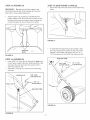
STEP 7: (SEE FIGURE
8 AND 9)
tf your tractor hitch has 10" to 13" ground clearance
refer to figure 8. if your tractor hitch has 8" to 10"
ground clearance refer to figure 9.
Assemble the hitch brackets to the hitch tubes using
two 5/16" x 2" hex bolts (B) and 5/16" nylock nuts (J).
The bolts should straddle the front hitch tube bolt. Do
not tighten yet.
At this time tighten the four bolts fastening the hitch
tubes to the sweeper housing. Next, tighten the two
bolts fastening the ends of the hitch tubes together.
Finally, tighten the two bolts fastening the hitch
brackets to the hitch tubes.
Assemble the hitch pin (BB), two 3/4" spacers (X) and
the 1/8" hair cotter pin (Q) to the hitch brackets.
STEP 8: (SEE FIGURE
10 AND 11)
, Assemble the height adjustment handle to the height
adjustment tube. Use two curved head bolts (C),
bowed washers (O), 5/16" lock washers (N) and 5/16"
hex nuts (K). Do not tighten yet.
, Assemble the grip (Z) onto the height adjustment
handle.
jGRIP
5116" LOCK
(Z)
HEIGHT
ADJUSTMENT
HANDLE
WASHER (N)
BOWED
WASHER (O)
CURVED
HEAD BOLT (C)
5/16" × 2"
HEX BOLT (B)
FIGURE 10
Insert a 5/16" x 3/4" hex bott (F) through the angle
bracket. Assemble onto the bolt (in order) the spacer
bushing (W), the height adjustment strap, a 5/16" flat
washer (M) and a 5/16" nylock nut (J). Tighten.
5116"
NYLOCK NUT (J)
FIGURE 8
5/16" x 3/4"
HEX BOLT (F)
5/16" FLAT
WASHER (M)
SPACER
BUSHING (W)
5/16" x 2"
HEX BOLT (B)
NYLOCK
NUT (J)
HmTCH PIN (BE)
;
_t:::=_
HITCH BRACKET
")
3/4" SPACER
(X)
BRACKET
5/16" HEX
LOCK NUT (J)
FIGURE 9
HEmGHT
ADJUSTMENT
STRAP
1/8" HAmR
COTTER PiN (Q)
FIGURE 11
STEP 9: (SEE FIGURE
®
ASSEMBLY
12)
Position the height adjustment handle side to side
so that the tooth lock washer (P) can fit between the
handle and the height adjustment strap, Tighten the
nuts securing the height adjustment handle,
insert the 5/16" x 1" carriage bolt (E) through the
height adjustment handle, Assemble onto the bolt,
in order, the 5/16" tooth-lock washer (P), the height
adjustment strap, a 5/16" flat washer (M) and the
plastic knob (AA),
OF HOPPER
BAG
STEP 10: (SEE FIGURE
13 AND 14)
Turn a rear hopper tube so that the brace holes in the
middle of the tube face down, Slide the tube through
the two loops sewn to the top rear seam inside the
hopper bag,
ruNNER BAG LOOPS
5116" FLAT
WASHER (M)
PLASTmC
KNOB (AA)
5/16" x 1"
CARRIAGE
REAR HOPPER TUBE
BOLT (E)
(brace holes on bottom)
FIGURE 13
TOOTH LOCK
WASHER (P)
insert the two upper hopper side tubes through the
stitched flaps on each side of the hopper bag,
Assemble the ends of the rear hopper tube onto the
ends of the upper hopper side tubes, Fasten together
using plastic plugs (CC),
LASTmCPLUG (CO)
FIGURE 12
?UPPERHOPPER
j
FIGURE 14
SmDETUBE
STEP 11: (SEE
STEP 12: (SEE FIGURE
,
,
FmGURE 15 AND 16)
Turn the second rear hopper tube so that the brace
holes in the middle of the tube face up. Assemble
the ends of the rear hopper tube onto the ends of the
lower hopper side tubes. Fasten together using plastic
plugs (CO).
17 AND 18)
insert the bag frame strap into the stitched sleeve
along the front edge of the bag bottom.
Assemble the bag frame strap to the lower hopper
side tubes using two 1/4" x 1ol/8" clevis pins (T) and
3/32" hair cotter pins (R).
REAR HOPPER TUBE
(brace holes on top}
PLASTmO
PLUG
1/4" × 1ol/8"
CLEVmS PIN (T)
(CO)
LOWER
HOPPER
StDE TUBE
FIGURE 17
FIGURE 15
Place the assembled lower hopper tubes into the
bottom of the hopper bag
Attach the ends of the lower hopper side tubes to the
inside of the upper hopper side tubes using two 3/8"
x 1/2" clevis pins (S) inserted from the inside, and two
3/32" hair cotter pins (R).
\
\
UPPER
SiDE
Secure the bag corners around the lower hopper side
tubes by snapping the bag flaps to the bag bottom on
both sides.
HOPPER
TUBE
3/32"
RAmP
COTTER PmN(R)
SNAP
c?
LOWER
SiDE
HOPPER
FIGURE 18
TUBE
3/8" x 1/2"
CLEVIS PmN(S)
HOPPER BAG
BOTTOM
FIGURE 16
STEP 13: (FIGURE
19)
STEP 15: (SEE FIGURE
,
IMPORTANT:
Do not over bend the support rods
during the following step. Over bending will cause the
steel rods to loose supporting tension.
21 AND 22)
Secure the rope to the top center of the hopper bag
frame.
Tip the hopper onto it's back to assemble the two
hopper support rods. Place the ends of each rod into
the upper and lower rear hopper tubes, bending the
rod just enough to fit into the holes in the tubes.
J
FIGURE 21
\
SUPPORT
RODS
To assemble the hopper bag to the sweeper, slide
the ends of the bag arm tubes into the ends of the
sweeper's hitch tubes and secure with two 1/4" x
1o3/4" clevis pins (U) and 3/32" hair cotter pins (R).
FIGURE 19
STEP 14: (FIGURE
,
,
BAG ARM
20}
insert a 3/8" x 3" clevis pin (V) through the lower hole
in each upper hopper side tube. Next assemble a bag
arm tube onto each clevis pin and secure it with a
3/32" hair cotter pin (R).
Assemble a vinyl cap (Y) onto the end of each bag
arm tube.
3/32"
3/32" HAiR
COTTER PUN(R)
HAgR
]
COTTER PmN(R)
3/8 x 3
VmNYLCAP (Y)
\
\
TUBE
CLEVIS PmN(V)
/
FIGURE
FIGURE 20
10
22
j
1/4" x 1-3/4"
CLEVmSPRN(U)
STEP 16: (SEE FIGURE
23, 24 AND 25)
Place the tractor and sweeper on a fiat level surface.
Set the sweeper height adjustment handle to about
the middle of its adjustment range.
Attach the sweeper hitch brackets to the tractor hitch,
arranging the 3/4" spacers so that the bottom of the
sweeper bag is approximately level and 5" to 7" above
the ground. See figure 24 for tractor hitches that are
10" to 13" above the ground. See figure 25 for tractor
hitches that are 8" to 10" above the ground.
IMPORTANT:
For best performance, the bottom of the
sweeper bag should be approximately level and 5" to 7"
off the ground as shown in figure 23,
FIGURE
Tractor
hitches
with
10" to 13" ground
clearance.
Tractor
23
hitches
with
8" to 10" ground
i
i
\
-?
\\
\\
\
TRACTOR HITCH
\
TRACTOR HmTCH
FIGURE 24
FIGURE 25
11
clearance.
\
\
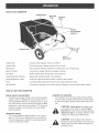
KNOW YOUR SWEEPER
WmNDSCREEN
HOPPER
ROPE
Hopper Bag
Collects grass clippings, leaves and debris,
Hopper Rope
Permits dumping of hopper bag from driver's seat,
Windscreen
Helps prevent collected material from being blown out of hopper bag,
Bag Arm Tubes
Connects the hopper bag to the sweeper housing,
Pivot Rod
Allows hopper bag to tilt forward to dump material,
Height Adjustment Handle
Adjusts the operating height of the sweeper,
Height Adjustment
Holds the height adjustment handle in position when locked,
Strap
Knob
Locks the height adjustment handle to the height adjustment strap,
Hitch Bracket
Connects the sweeper to the towing vehicle, Adjusts for various height tractor hitches,
HOW TO USE YOUR SWEEPER
DUMPING OF SWEEPER
Your sweeper can be dumped easily without getting
off of the rider or tractor, Simply pul! the rope forward
to dump the hopper, Always empty hopper after each
BRUSH HEIGHT ADJUSTMENT
To adjust your sweeper brushes to the best operating
height, loosen the adjustment knob and push down on
the height adjustment lever to raise the brush, or push
up on the lever to lower the brush, See figure 20, Best
adjustment is when the brush setting is 1/2" down into
the grass, Always mow the grass to an even height
before sweeping,
use=
CAUTION:
Never attach the hopper rope
to any part of your body or clothing! Never
hoJd onto the rope while towing the sweeper!
Attach the rope to the towing vehicle to keep
it away from wheels and rotating parts,
SWEEPING SPEED
,
Try a starting speed of approximately 3 m,p,h, (third
gear on most tractors), Depending on the conditions,
it may be necessary to adjust the sweeping speed in
order to achieve best results,
CAUTmON: Keep sweeper away from fire,
Excessive heat can damage the brushes and
hopper bag and could cause the bag and its
contents to burn,
12
CUSTOMER
RESPONSIBILmTmES
Read and follow the maintenance schedule and the
procedures listed in the maintenance section.
MAINTENANCE SCHEDULE
Fi,, in dates as you
complete regular service.
__
_.7,1S
Check for loose fasteners
X
Check for worn or damaged parts
X
Lubricate brush shaft bearings
Lubricate wheel bearings
Ctean Sweeper
-- _
Clean/Lubricate chain and sprockets
SCHEDULED
Service Dates
X
_ X ..................
X
-- -- _
-X
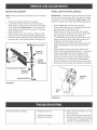
MAINTENANCE
Clean the sweeper after each use.
inspect for worn or damaged parts, such as brushes
and wheels.
Lubricate the brush shaft bearing twice a year with a
few drops of light weight oil. See figure 26.
HEIGHT ADJUSTMENT
HEX BOLT
FLAT WASHER
FLAT WASHER
HUB CAP
SLOT
SPACER
FLAT WASHER
HEX LOCK NUT
FIGURE 27
HEX BOLT
FIGURE 26
CLEANING
Every two years, remove the wheels and clean the
gears found inside the wheel housing. After cleaning,
lubricate the gears with an even coat of light grease.
To remove the wheel, pop off the hub cap and remove
the Iock nut and fiat washer. See figure 27.
.
Clean sweeper housing with a soft brush or cloth.
Clean debris from hopper bag with a brush or broom.
Remove any material which has wrapped around
brushes or ends of brush shaft.
Clean the sweeper and hopper bag thoroughly to help
prevent rust and mildew.
To collapse the hopper bag for storage, remove the two
hopper support rods from the rear of the hopper.
Store in a dry area.
CAUTION: Before storing the sweeper,
always empty the hopper bag to avoid
spontaneous combustion.
13
BRUSH
REPLACEMENT
WHEEL
Remove the hopper bag from the sweeper.
Loosen the hex bolts and lock nuts on two single
brush retainers which clamp one brush to the double
brush retainers. Do Not loosen or remove the bolts
which fasten the double brush retainers to the brush
shaft. See figure 28.
Slide the brush out of the retainers, noting on which
side of the brush the bristles overlap. See figure 28.
Install new brush, making sure the bristles overlap on
the same side of the brush as before. See figure 28.
BRUSH
SHAFT
AND PAWL SERVICE
IMPORTANT:
Do not remove both wheels at the same
time to avoid mixing of parts. (The R.H. and LH. ratchet
sprockets are not interchangeable.) Make notes on the
position of washers and snap rings during disassembly.
NOTE: Brush replacement should be done one brush at
a time=
BRUSH
GEAR
,,
ROTATION
OVERLAP
BRmSTLES
SINGLE
,BRUSH
RETAINERS
,
Remove only one wheel from the sweeper.
Remove the retaining rings and washers which hold
the ratchet gear on the brush shaft.
Slide the gear off of the brush shaft. (Look for the
drive pin, which may fall out of the brush shaft when
the ratchet gear is removed.) See figure 29.
To reassemble, insert the drive pin through the hole
near the end of the brush shaft. Make sure the pin
slides back and forth easily in the shaft.
Lightly grease the shaft and fill the ratchet gear with
grease. Assemble the ratchet gear back onto the
shaft.
Lightly grease the axle and the gear teeth on the
wheel, and then reassemble the wheel. The brushes
should rotate only during forward rotation of the
wheel. If the brushes are driven (rotated) by both
forward and reverse rotation of the wheel, the drive
pin is jamming in the ratchet gear. Disassemble to
clean and lubricate the drive pin and the ratchet gear.
Remove the second wheel and repeat the procedure.
RATCHET
GEAR
BRUSH
ROTATmON
FIGURE 28
FIGURE
Wheels skid when sweeping.
,
29
Brushes set too low.
,
Brushes are jammed
Wheels are jammed.
,
Adjust height till brushes are 1/2"
down into grass.
Stop sweeper. Remove obstruction.
Remove one wheel at a time to check
for obstruction or damage. Refer to
Service and Adjustments section.
14
15
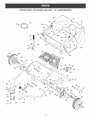
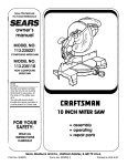
REPAUR PARTS FOR MODEL
486.24221
- 42" LAWNSWEEPER
45
44
47
53
59_
49
50
48
20
61
6O
77
61
X
46
_21
43
26
3
5
9
'l
29
13
\
72
62
39
67
54
69
35
29
43
34
/
37
35
75
71
39
41
31
3O
33
/
26
29
29
16
60
REPAIR PARTS FOR MODEL 71-24221,42"
Ref,
No.
Part
No.
Qty.
1
2
3
4
5
6
7
8
9
10
11
12
13
14
15
16
17
18
19
20
21
22
23
24
25
26
27
29
30
31
32
33
34
35
36
37
38
39
40
41
48306
48305
24950
24951
24869
43175
C-9M5732
24185
43182
23826
23336
64540
44947
44695
43086
43083
R19212113
1629-56
44910
25850
48557
43012
47189
23580
23581
44008
47046
47810
44911
44006
46219
1650-21
40001
141
1038
2674-32
44961
23400
48652
48651
1
1
1
1
1
2
14
1
6
1
2
1
2
2
2
2
2
2
2
1
4
8
14
4
8
2
2
14
2
2
2
2
10
4
2
2
2
3
1
1
Description
Hitch Tube, R.H.
Hitch Tube, LH.
End Plate, R.H.
End Plate, LH=
Wrapper
Bolt, Hex 1/4-20 x 1/2" Lg.
Rivet, Pop
Brace, Rear Support
Bolt, Hex 5/16-18 x 3/4"
Bracket, Angle
Washer, Special
Height Adjustment Tube Assembly
Bolt, Cvd. Hd. 5/16-18 x 1-5/8" Lg.
Washer, Bowed 1" x .32" x .06"
Lock Washer, 5/16"
Nut, Hex 5/16-18 Thread
Washer, 5/8" SAE
Retainer, Dust Cover
Bushing, Brush Shaft
Brush Shaft
Brush
Bolt, Hex 1/4-20 x 3/4" Lg.
Nut, Nylock 1/4-20
Retainer, Brush (Double)
Retainer, Brush (Single)
Washer, Flat 1-1/8" x .78" x .025"
Dowel Pin (Drive)
Nut, Nylock 5/16-18
Spacer, =39 I=D"=x 1-1/4" O=D=x =5"
Washer, Flat .849" x .598" x .025"
Spacer, =78 I=D"=x 1-1/4" O=D=x =5"
Ring, Retaining =594"
Washer, Shim 1-1/4" x .594" x .010"
Washer, Flat 1-1/2" x .375" x .062"
Nut, Nylock Jam 3/8-24 Thread
Hub Cap
Bolt, Hex 3/8-24 x 3-1/4" Lg=
Bushing, Spacer
Gear, Pinion R=H=(not shown)
Gear, Pinion LH=
17
LAWNSWEEPER
Ref°
No.
Part
No.
Qty.
42
43
44
45
46
47
48
49
50
51
52
53
54
55
56
57
58
59
60
61
62
63
65
66
67
68
69
70
71
72
73
74
75
76
77
43661
64559
48587
48466
48726
48402
48388
48366
24949
43926
43737
44481
24979
23687
24192
23850
48323
43513
44985
45088
44292
44180
43681
R19111116
43720
44326
43081
43943
44732
23353
23368
43343
43055
46867
48365
49994
4
2
2
2
2
4
1
2
1
2
1
2
1
1
1
1
2
2
2
4
2
2
4
2
1
1
2
1
1
1
2
1
8
2
2
1
Description
Bolt, Hex 1/4-20 x 1" Lg.
Ass'y, Dust Cover
Tube, Hopper Frame (Rear)
Tube, Upper Hopper Frame (Front)
Tube, Lower Hopper Frame (Front)
Plastic Plug
Hopper Bag
Clevis Pin, 3/8" x 1/2"
Strap, Bag Frame
Rod, Hopper Support
Hopper Rope
Cap, Vinyl
Strap, Height Adjustment
Bracket, Hitch
Bracket, Hitch (Straight)
Handle, Height Adjustment
Tube, Bag Arm
Pin, Clevis 3/8" x 3"
Wheel & Tire Ass'y= (with bearings)
Whee_ Bearing
Bolt, Hex 5/16-18 x 2-1/2" Lg.
Bolt, Hex 5/16-18 x 2" Lg.
Bolt, Carriage 5/16-18 x 1-1/2"
Washer, Flat (5/16) 11/32" x 11/16"
Knob, Wing 5/16-18 Thread
Bolt, Carriage 5/16-18 x 1"
Washer, Flat 5/16" Std= Wrt=
Grip, Height Adjust
Washer, Tooth Lock 5/16"
Pin, Hitch
Tube, Hitch Spacer
Hairpin Cotter, 1/8" #4
Hairpin Cotter, 3/32" #3
Clevis Pin, 1/4" x 1-3/4" Lg=
Clevis Pin, 1/4" x 1-1/8"
Owners Manua!
18
19
Your Home
For repair-in
your home-of all major brand appliances,
lawn and garden equipment, or heating and cooling systems,
no matter who made it, no matter who sold it!
iiiiiiiiiiiiiiiiii
For the replacement parts, accessories and
owner's manuals that you need to do-it-yourself.
iiiiiiiiiiiiiiiiii
iiiiiiiiiiiiiiiiii
For Sears professional installation of home appliances
and items like garage door openers and water heaters.
iiiiiiiiiiiiiiiiii
1-800-4-MY-HOME
Call anytime,
iiiiiiiiiiiiiiiiii
®
(1-800-469-4663)
day or night (U.S.A. and Canada)
www.sears.com
www.sears.ca
® Registered Trademark
/ TM Trademark / SMService Mark of Sears Brands, LLC
® Marca Registrada / TM Marca de F_brica / SM Marca de Servicio de Sears Brands,
MC Marque
de commerce
/ MD Marque
d_pos_e
de Sears
Brands,
LLC
LLC
® Sears Brands, LLC
iiiiiiiiiiiiiiiiii
iiiiiiiiiiiiiiiiii
iiiiiiiiiiiiiiiiii
iiiiiiiiiiiiiiiiii
iiiiiiiiiiiiiiiiii
iiiiiiiiiiiiiiiiii
iiiiiiiiiiiiiiiiii
iiiiiiiiiiiiiiiiii
iiiiiiiiiiiiiiiiii
iiiiiiiiiiiiiiiiii
iiiiiiiiiiiiiiiiii
iiiiiiiiiiiiiiiiii
iiiiiiiiiiiiiiiiii
iiiiiiiiiiiiiiiiii
iiiiiiiiiiiiiiiiii
iiiiiiiiiiiiiiiiii
iiiiiiiiiiiiiiiiii