1
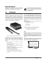
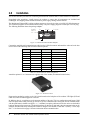
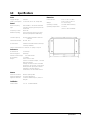
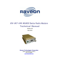
XStream-Pkg
Wireless Modem
Operation
Manual
69795
Contents
1.0
Introduction.................................................................................................................................. 1
2.0
3.0
Installation ................................................................................................................................... 2
Operation...................................................................................................................................... 3
3.1 Standby ............................................................................................................................................. 3
3.2 Transmitting ....................................................................................................................................... 3
3.3 Receiving ........................................................................................................................................... 3
4.0
MaxStream Commands ............................................................................................................... 4
4.1 Binary Commands.............................................................................................................................. 4
4.2 AT Commands ................................................................................................................................... 4
4.2.1
4.2.2
4.2.3
4.2.4
Entering AT Command Mode .....................................................................................................................
AT Command Response ............................................................................................................................
Reading Parameters from Radio .................................................................................................................
Exiting AT Command Mode........................................................................................................................
5
5
5
5
4.3 Low Power Modes ............................................................................................................................. 7
4.3.1 Pin Power Down......................................................................................................................................... 7
4.3.2 Cyclic Power Down .................................................................................................................................... 7
4.3.3 Receiver Power Down ................................................................................................................................ 7
5.0
Networking with the XStream ..................................................................................................... 8
5.1 Vendor IDentification Number (VID)..................................................................................................... 8
5.2 Radio Groups..................................................................................................................................... 8
5.3 Radio ADdress (RAD) ......................................................................................................................... 8
5.3.1 RAD Mask .................................................................................................................................................. 8
6.0
Specifications .............................................................................................................................. 9
© 2005 Rice Lake Weighing Systems. All rights reserved. Printed in the United States of America.
Specifications subject to change without notice.
March 2005
i
About This Manual
This manual is intended for use by service technicians
responsible for installing and working with the
MaxStream™ XStream-PKG wireless modem.
1.0
Authorized distributors and their employees
can view or download this manual from the
Rice Lake Weighing Systems distributor site
at www.rlws.com.
Introduction
The MaxStream XStream-PKG wireless modem is
designed to provide users with an easy to install
wireless communication link between equipment using
a standard asynchronous serial data stream.The modem
can transfer data up to 1/4 mile in a city environment or
greater than seven miles line-of-sight with a directional
antenna. The modem supports 8 data bits, no parity, and
1 stop bit. These settings cannot be changed.
The radios integrate quickly and seamlessly into any
new or existing design. Output serial data from any
microcontroller, weight indicator, or RS-232 port into
the radio to send FCC approved, frequency hopping
spread spectrum data through the air and capture it on
all receivers within range on the same network. The
system behaves as a virtual half-duplex, parallel-wired
network.
The Maxstream XStream-PKG wireless modem comes
with the following:
•
•
•
900 MHz wireless modem
Power supply
RS-232 cable
Optional components of the MaxStream include:
•
•
3" one-quarter wave monopole antenna
6" one-half wave dipole antenna
Note:
Figure 1-1. MaxStream XStream-PKG Modem
The MaxStream XStream-PKG wireless modem is
perfect for a wide variety of applications ranging from
weighing scales, printer control, data acquisition,
wireless LANs, to instrument monitoring. Features
include:
•
•
•
•
•
•
The system integrator must also ensure that the
external label (shown below), provided with this device
is placed on the outside of the final product.
0.60"
•
Best sensitivity in the industry for extended
transmission range.
Low power consumption. Suitable for battery
powered applications.
Easy to integrate. No knowledge of RF necessary.
Simple networking protocol.
Standard serial digital interface. Interfaces with any
microcontroller or weight indicator.
Reliable data transfer performance.
Choice of integral or separate external antennas.
FCC approved with no further licensing or approval
required.
To comply with the FCC RF exposure requirements, the
MaxStream XStream-PKG can only be used with
approved antennas that have been tested with this
modem and a minimum separation distance of 20 cm
(8") must be maintained from the antenna to any nearby
persons.
This device contains transmitter module
FCC: ID: OUR9XTREAM. The enclosed
device complies with Part 15 of the FCC
Rules.
Operation is subject to the following two
conditions: (1) This device may not cause
harmful interference, and (2) this device
must not accept any interference received,
including interference that may cause
undesired operation.
1.32"
Figure 1-2. External Label
Introduction
1
2.0
Installation
This section describes procedures for connecting the MaxStream XStream-PKG wireless modem to a host device.
Immediately after unpacking, visually inspect the modem to ensure that all components are included and
undamaged. The shipping carton contains the modem, power supply, cabling, and this manual.
The MaxStream XStream-PKG wireless modem connects to a host device using a 9 pin RS-232 D-Sub connector.
This connection supplies serial communications hookup. The power supply plugs into a round pin 7-18VDC plug.
The following illustration shows the package endplate.
POWER
SWITCH
UP = ON
RX
7-18 VDC
RS-232
1
PWR/TX
Figure 2-1. MaxStream XStream-PKG Endplate
Connect the supplied serial communications cable into the 9 D-Sub connector and attach the other end to the host
device. Refer to the following chart for serial connector pinouts.
Signal
Pin
Type
Description
1
NC
—
No connect
2
RXD
Output
Data
3
TXD
Input
Data
4
DTR
Input
Sleep control
5
SGND
Ground
Common return
6
NC
—
No connect
7
RTS
Input
Binary program control
8
CTS
Output
Clear to send control
9
NC
—
No connect
Table 2-1. Serial Connector Pinout Assignments
Attach the optional 3" or 6" antenna to the opposite side of the modem (see antenna location below).
Figure 2-2. Antenna Location
Power up the modem by turning on the ON switch located on the backplate of the modem. LED lights (RX and
PWR/TX) will be lit indicating power to the unit.
In addition, there is a push button on the antenna endplate of the unit. This is a configuration push button. Hold
down the push button while powering up the unit to go into command mode. Placing the unit in command mode
with the push button is similar to using the “+++” command, except the push button forces the unit to use the default
baud rate instead of the current one. The default baud rate for the unit is 9600 and is the only parameter that can be
changed. Data Bits and Parity and Stop Bits cannot be changed. Their default is: Data Bits = 8, Parity = None, Stop
Bits = 1. See Section 4.0 on page 4 for more information about command modes.
2
MaxStream XStream-PKG Wireless Modem Operation Manual
3.0
Operation
There are various operating states associated with the operation of the MaxStream XStream-PKG wireless modem.
The following sections describe the stages of operation.
3.1
Standby
When the radio is not transmitting or receiving, it is in standby mode and ready to receive data. From standby, the
radio can either transmit, if data is presented on the serial port; or receive, if data is presented over the air. The radio
returns to standby when data is no longer present either on the air or on the serial port, or if a receive error is
detected.
3.2
Transmitting
The MaxStream modem leaves standby mode when data is received by the serial port which then sends incoming
data through the air. Once in transmit mode, the modem starts to send buffered data. Data is sent in packets up to 64
bytes long. When the first byte is clocked into the transmit buffer, the modem begins the transition from standby to
transmit.The transition between standby mode and transmit mode take approximately 35 milliseconds (ms) which is
the approximate length of time it takes for the modem to receive serial port data and then transmit serial port data.
After the 35ms transition time, any bytes that are in the buffer are packetized and sent over the air.
The MaxStream XStream-PKG can buffer up to 132 characters before it must stop receiving characters. The
modem will de-assert the CTS flow control line when approximately 116 characters have been received to notify the
sending device to stop sending data. When the first packet has been transmitted if more bytes are in the buffer, they
are packetized and sent. If the buffer is empty, the modem transitions to standby mode.
3.3
Receiving
If data is present on the airwaves when the modem is in standby, it transitions to the receive mode. In receive mode
it receives a packet and transmits it out the serial port. Received packets are protected from data corruption by a
16-bit CRC. A packet is rejected and not sent out of the serial port if there is an error detected in the packet.
The modem stays in receive mode until no more data is detected or an error is detected. A modem in receiving mode
does not transmit data coming in to the serial port until after returning to standby mode. When there are gaps in
receiving data, the receiver automatically returns to standby mode. If the receiver has buffered data coming in to the
serial port, this data is sent after the modem returns to standby mode.
Operation
3
4.0
MaxStream Commands
The MaxStream XStream-PKG is available with advanced power-down and addressing options. These options can
be configured through either of the two command modes, binary, or AT commands. By default, all data received on
the RX pin is transmitted on the RF channel. The command modes differentiate commands from the data and allow
various operating parameters to be changed. These parameters that are changed can be saved in volatile memory to
be discarded when the modem powers off or is reset, or in non-volatile memory to be saved and used until they are
rewritten again.
4.1
Binary Commands
Send a binary command by asserting the RTS pin (pin 7) high and send the binary bytes that represent a command
and its parameters. Binary command bytes are organized as follows:
<Command><Parameter 1><Parameter...><Parameter N>
A command is one byte long. Parameters are two bytes long. “<” and “>” characters are used to indicate parameters
and are not actually part of the command.
The command type should be sent with RTS asserted. Do not de-assert RTS until after the stop bit of the last byte is
sent. It does not matter whether RTS is asserted when the parameters are sent. The command executes when all the
parameters associated with the command are sent. If all parameters haven’t been sent within 0.5 seconds, the
modem returns to data mode.
Commands can be queried for their current value by sending the command logically ORed with the value 0x80
hexadecimal with RTS asserted. No parameters are sent and the current value of the parameter is immediately sent
out the serial port. If the parameter is 2 bytes long the least significant bit is sent first.
Note: When parameters are sent, they are always two bytes long; when they are read they are one or two bytes
long as indicated in the command table shown on page 5.
An example of binary commands include:
To set sleep mode to pin power down and store to non-volatile memory:
•
•
•
4.2
Assert RTS
Send bytes: 0x01, 0x00, 0x08
De-assert RTS
AT Commands
AT commands are accessed through ASCII commands and parameters that can be sent from a terminal program
such as HyperTerminal. AT commands are sent as follows:
<AT><2 character command><space><parameter><CR>
•
•
•
All characters must be ASCII displayable characters
All alphabetic characters can be sent upper and lower
case
All parameters must be made from ASCII
hexadecimal characters (0-9, a-f, A-F). Parameters
•
•
can be up to four characters long. All parameters are
specified as hex values.
A space can be any non-alpha-numeric character.
Carriage return (CR) is a byte value of 13 decimal
(0x0D).
Example:Send the following sequence of characters to change the user-defined address to 1A0D (hex).
+++
ATDT 1A0D<CR>
ATWR<CR>
ATCN<CR>
4
MaxStream XStream-PKG Wireless Modem Operation Manual
4.2.1
Entering AT Command Mode
Commands and data are both sent to the same serial UART on the MaxStream modem. A special break sequence
must be sent to get the modem into AT command mode. After the sequence all subsequent characters are interpreted
as commands and are sent as data.
The default sequence for command mode is:
1. No characters sent for one second (before command character time, change with ATBT).
2. Send three plus characters “+++” (command entry character, change with ATCC).
3. No characters sent for one second (after command character time, change with ATAT).
4. The XStream modem responds by sending an OK<CR>.
The before command character time, after character time and command entry character can all be changed by AT or
binary commands.
4.2.2
AT Command Response
After a recognized and executed AT command the modem responds with an OK<CR>. After unrecognized
commands with bad parameters an ERROR<CR> is sent.
4.2.3
Reading Parameters from Radio
If an AT command is sent without any parameters (carriage return <CR> is still sent), the response is the current
value of that command reported as a hexadecimal number. Example: ATSM<CR> returns the current power down
mode setting.
4.2.4
Exiting AT Command Mode
There are two ways to exit the AT command mode and return to data mode. If no valid AT commands are received
within the AT command time-out (ATCT) time, the modem returns to data mode automatically. Alternatively, the
AT command mode can also be exited by sending the ATCN command.
Binary
AT
Command Command #
DT
0 V4.08
SM
Description
# Bytes
Returned Factory
For Binary Default
Parameters
Set the Radio ADress (RAD). Only radios
with the same address can communicate.
Address from 0-65535
2
0
1
Set power down mode
0 - No sleep mode
1 - Sleep on pin
2 - Wake from serial RX
3 - Cyclic 0.5 second sleep
4 - Cyclic 1.0 second sleep
5 - Cyclic 2.0 second sleep
6 - Cyclic 4.0 second sleep
7 - Cyclic 8.0 second sleep
1
0
ST
2
Set time to sleep. Time of inactivity before
entering power down mode (this number is
only valid in RX and cyclic modes).
Number of tenths of seconds. Valid from
1 to 65535.
2
64
HT
3
Set time before long header. Time of
inactivity on RX pin before a long header is
used.
Number of tenths of seconds. Valid from
0 to 65535. 65535 means no long
header.
2
FFFF
BT
4
Set silence time after command sequence.
Number of tenths of seconds.
Valid from 1 to 65535
2
A
AT
5
Set silence time after command sequence.
Number of tenths of seconds.
Valid from 1 to 65535
2
A
CT
6
Set time out from AT command mode.
Causes a return from AT mode after no
valid commands have been received.
Number of tenths of seconds.
Valid from 1 to 65535
2
C8
FL
7
Set serial software flow control. Hardware
flow control (CTS) is always on.
0 - No software flow control
1 - Use software flow control
1
0
Table 4-1. MaxStream Command Table
MaxStream Commands
5
AT
Binary
Command Command #
WR
8
Description
Write all configurable parameters to
non-volatile memory. All setable
parameters are stored.
Parameters
No parameters
NA
NA
CN
9
Exit AT command mode
No parameters
NA
NA
E0
10
No echo in AT command mode
No parameters
NA
NA
NA
NA
1
1
E1
11
Echo characters in AT command mode
No parameters
LH
12
Transmit beacon time
Time in tenths of seconds for the wake up
beacon
FH
13
Force beacon on next transmit
No parameters
NA
NA
RE
14
Restore defaults configuration
No parameters
NA
NA
ER
15
Set receive error count
Value of error count. This value is reset to
0 after every reset it is not non-volatile
2
0
GD
16
Set receive good count
Value of good count. This value is reset to
0 after every reset it is not non-volatile
2
0
HP
17
Set group number. Each radio group uses
a different hop sequence. Seven different
group numbers available.
Number 0 to 6. Use this parameter to
operate independent networks of
XStream radios in the same vicinity.
1
0
MK
18
Set RAD mask (Radio ADdress mask)
Address mask. Only bits set to 1 is used
in the address comparision. A global
address is an address that has the same
bits set as the address mask.
2
FFFF
CC
19
Set command sequence character
Number for the command character. Valid
from 32 to 127.
1
2B
VR
20
Firmware version
Firmware version
2
NA
BD
21 V4.08
Set UART baud rate
Number corresponding to UART baud
rate. Baud rate doesn’t take effect until
ATCN command is issued. If the baud
command is issued in binary mode it
must be stored (ATWR) and a new baud
rate will take affect after reset
1 - 2400
2 - 4800
3 - 9600
4 - 19200
5 - 38400
6 - 57600
1
3
RT
22 V4.10
RTS Control
0 - No binary commands accessed with
RTS
1- Binary commands are sent when RTS
is asserted
1
0
SY
23 V 4.12
Set sync timer
Time in tenths of seconds that the
transmitter and receiver stay in sync after
receiving or sending data. Setting this
parameter to 20 (0x14) will allow any
radio to transmit within the next 2
seconds utilizing a beacon of 8ms instead
of 35ms. Use this parameter to speed up
communication latency and turn-around
time.
1
0
Table 4-1. MaxStream Command Table (Continued)
6
# Bytes
Returned Factory
For Binary Default
MaxStream XStream-PKG Wireless Modem Operation Manual
4.3
Low Power Modes
The MaxStream XStream-PKG wireless modem has several low power modes that enable it to be used in low
power or battery operated environments. While in low power mode, it is only able to check for whatever stimulus
will return the modem to power up mode. No transmitting or receiving can occur.
The power modes and the current usage definitions are listed below:
Power Mode
Description
Current
Pin power down
An RS-232 input is used to power down the XStream-PKG module
< 2 uA
Cyclic power down
The modem goes into a low power mode automatically after a defined period of time of
no activity (no received character on the RF channel).
50 uA
Receiver power down The modem powers down automatically after not receiving characters on the serial
channel for a user-defined period of time. Any serial channel received character will
bring the modem to a power up condition.
1 mA
Standby
The modem is fully operational and is currently scanning channels for valid data.
50 mA
Transmitting
The modem is fully operational and is currently transmitting data.
150 mA
Table 4-2. MaxStream XStream-PKG Power Modes
4.3.1
Pin Power Down
Pin 4 (pwrdwn), on the 9-pin connector controls whether the MaxStream XStream-PKG is in power up or power
down mode. If pwrdwn is low, the modem is powered up and fully operational. If pwrdwn is high, the modem is in
its lowest power mode. This mode allows the lowest power consumption but also requires the user to completely
control the power up and power down of the modem. The modem requires 20 milliseconds to transition from power
down to power up mode. The pwrdwn pin is only active if the modem is set up to operate in this mode, otherwise the
pin is ignored.
4.3.2
Cyclic Power Down
The modem goes into low power mode after a user-defined period of inactivity (no transmission or reception on the
RF channel). The modem remains in the low power mode for a user-defined period of time ranging from 0.5 to 8
seconds. After this period of time the modem returns to power up mode and scans all RF channels for a valid data
packet. If no data packet is found on any channel, the modem returns to low power mode.
If a data packet is found the modem remains powered up and receives the packet and any following packets until
another inactivity timeout. The modem returns to the low power mode after the inactivity time period.
Note:
The modem requires 35 milliseconds (ms.) to scan all channels. The modem requires 20 milliseconds to transition
from low power to power up mode.
4.3.3
Receiver Power Down
The modem goes into power down after a user-defined period of inactivity on the serial receive channel. The
modem transitions to power up mode when a character is received on the serial receive channel.
MaxStream Commands
7
5.0
Networking with the XStream
The MaxStream XStream-PKG wireless modem is built around a peer-to-peer protocol that inherently supports a
multi-drop type network (similar to RS-485). In their default state, any XStream modem will communicate with any
other XStream modem in its default state. When one modem transmits, all other modems within range will tune into
the transmission and output the data received out of the serial port.
While this provides flexibility in system design, addressing the need for isolation and security in a wireless world,
the XStream modules append three levels of addressing to a data packet before transmitting it over the air. Other
XStream radios within range monitor the radio channels and use the addresses to determine what to do with a
packet. There are three types of addressing. They are:
•
•
•
5.1
Vendor IDentification number
Group addresses
Radio addresses
Vendor IDentification Number (VID)
For network security, a system integrator can request a
Vendor IDentification number (VID) that is
programmed into the XStream module at the factory.
This number is stored in permanent memory and can
only be changed at the factory. Only modems with
matching VID numbers can communicate together. The
VID addressing ensures that modems used by one
system integrator are immune to either transmissions or
receptions with other XStream modems which are
located in the same area but not running by the same
system integrator.
5.2
Radio ADdress (RAD)
Each radio/modem in a sub-domain can be configured
with a 16-bit radio address (RAD) to establish
point-to-point or selective communication between
radio groups. This is done using the ATDT command or
its equivalent binary command. This commands sets a
RAD for a radio. There are 65535 packet addresses
available and has a default RAD of zero. The default
global RAD is 0xFFFF. Every radio in a group receives
packets from a radio with a RAD of 0xFFFF regardless
of what their RAD is set to. Except for global RADS,
only radios with the same RAD can communicate.
8
•
•
•
Radio Groups
Within each VID, there are seven available
radio/modem group addresses. Each group utilizes a
different random hopping sequence to navigate through
shared hopping channels. In the event that two modems
from different groups collide on a channel, because
they hop in a different sequence, the two modems will
jump to separate channels after another hop. Using
modem groups, multiple modem pairs can operate in
the same vicinity with minimal interference from each
other. The group parameter is user settable using the
ATHP command or equivalent binary command.
5.3
If a radio group consists of three or more radios, a RAD
can be used to communicate selectively to individual
radios (radios A, B, and C) as follows:
5.3.1
Set the RAD of radios A and B to unique values
within the subdomain.
To communicate only with radio B, set the RAD of
radio C to match that of radio B. Now radios B and C
can transmit and receive data and though radio A will
tune into a transmission, no data will be sent out the
UART of radio A because its RAD doesn’t match.
When a radio observes that data is being sent to a
RAD that doesn’t match his, it will still listen to the
whole message in order to maintain network
sychronization and will not transmit while a message
is being sent with a different RAD.
RAD Mask
A Radio ADdress Mask is also available to facilitate
networking within a radio group and broadcasting
messages to groups of radios. The RAD Mask is set
using the ATMK command. The RAD Mask is the
same length as the RAD (16 bits) and is set to 0xFFFF
from the factory. Any bits set in the RAD Mask are
compared against the RAD. Any bit cleared in the RAD
Mask are ignored. The RAD Mask is used as the global
address so if the RAD Mask is changed, the global
address will be the new RAD Mask. This allows for
sub-networks of radios which are still independently
addressable and have individual global addresses, i.e.:
0x000F, 0x00F0, 0x0F00, and 0xF000.
MaxStream XStream-PKG Wireless Modem Operation Manual
6.0
Specifications
Power
Supply voltages
Power Consumption
Dimensions
7-8 VDC
Tx 210 mA, Rx 70 mA, Sleep TBD
General
Radio Frequency
Type
Frequency Control
Network Topology
Channel Capacity
Serial Data Interface
902-928 MHz, unlicensed ISM band
Frequency hopping spread spectrum
transceiver
Direct FM
Point multi-point and point-to-point
multi-drop transparent networking
Enclosure Size
Weight
Operating Humidity
Operating Temperature
2.75" x 5.50" x 2.1875"
7.90 x 13.90 x 3.80 cm
6.9 oz (195.61g)
10–90% relative humidity
0 to 70°C
(-40°C to 80°C available)
65,000 network identifiers share 25
channels
RS-232, DCE
I/O Data Rate
Software selectable 2400-57,600 bps,
1200 bps available
Serial Communications 8 data bits, no parity, 1 stop bit
Performance
RF Baud Rate
10,000 bps
Data Throughput
9600 bps
Transmit Power Output
100 mW nominal
Rx Sensitivity
-110 dBm
Range*
Indoor: 600 to 1500’
Outdoor: 7 miles with dipole, > 20 mile
with gain antenna
*Range calculations are for the 9600
baud radio, line-of-sight. Actual range
will vary based upon specific board
integration, antenna selection,
environment, and the OEM’s device.
Antenna
Antenna Connector
Antenna Impedance
Approved Antenna
Reverse-polarity SMA
50 ohms unbalanced
1/2 wave flexible whip (6"), SMA, 2.1
dBi gain
Certification
United States
FCC ID: OUR9XSTREAM
Specifications
9