1
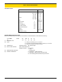
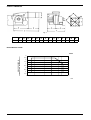
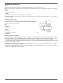
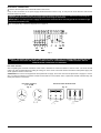
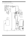
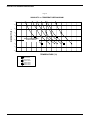
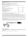
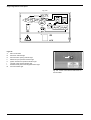
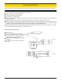
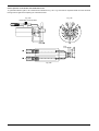
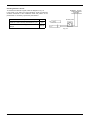
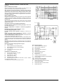
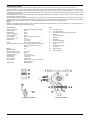
MANUAL OF
- INSTALLATION
- OPERATION
- MAINTENANCE
HEAVY OIL BURNERS
PN30
SINGLE STAGE VERSION
M03930CC Rev. 02 06/01
Technical Documentation CIB Unigas - Campodarsego (PD)
NOTICES
THIS MANUAL IS SUPPLIED AS AN INTEGRAL AND ESSENTIAL PART OF THE PRODUCT AND MUST BE DELIVERED
TO THE USER.
INFORMATION INCLUDED IN THIS SECTION ARE DEDICATED BOTH TO THE USER AND TO PERSONNEL FOLLOWING
PRODUCT INSTALLATION AND MAINTENANCE.
THE USER WILL FIND FURTHER INFORMATION ABOUT OPERATING AND USE RESTRICTIONS, IN THE SECOND SECTION OF THIS MANUAL. WE HIGHLY RECOMMEND TO READ IT.
CAREFULLY KEEP THIS MANUAL FOR FUTURE REFERENCE.
1)
GENERAL INTRODUCTION
2)
SPECIAL INSTRUCTIONS FOR BURNERS
! The equipment must be installed in compliance with the
! The burner should be installed in a suitable room, with ven-
regulations in force, following the manufacturer’s instructions, by qualified personnel.
! Qualified personnel means those having technical knowledge in the field of components for civil or industrial heating
systems, sanitary hot water generation and particularly service centres authorised by the manufacturer.
! Improper installation may cause injury to people and animals, or damage to property, for which the manufacturer
cannot be held liable.
! Remove all packaging material and inspect the equipment
for integrity.
In case of any doubt, do not use the unit - contact the supplier.
The packaging materials (wooden crate, nails, fastening devices, plastic bags, foamed polystyrene, etc), should not be left
within the reach of children, as they may prove harmful.
! Before any cleaning or servicing operation, disconnect the
unit from the mains by turning the master switch OFF, and/
or through the cut-out devices that are provided.
! Make sure that inlet or exhaust grilles are unobstructed.
! In case of breakdown and/or defective unit operation,
disconnect the unit. Make no attempt to repair the unit or
take any direct action.
Contact qualified personnel only.
Units shall be repaired exclusively by a servicing centre, duly
authorised by the manufacturer, with original spare parts.
Failure to comply with the above instructions is likely to impair
the unit’s safety.
To ensure equipment efficiency and proper operation, it is
essential that maintenance operations are performed by qualified personnel at regular intervals, following the manufacturer’s instructions.
! When a decision is made to discontinue the use of the
equipment, those parts likely to constitute sources of danger shall be made harmless.
! In case the equipment is to be sold or transferred to
another user, or in case the original user should move and
leave the unit behind, make sure that these instructions
accompany the equipment at all times so that they can be
consulted by the new owner and/or the installer.
! For all the units that have been modified or have options fitted then original accessory equipment only shall be used.
! This unit shall be employed exclusively for the use for
which it is meant. Any other use shall be considered as
improper and, therefore, dangerous.
The manufacturer shall not be held liable, by agreement or
otherwise, for damages resulting from improper installation,
use and failure to comply with the instructions supplied by the
manufacturer.
tilation openings complying with the requirements of the
regulations in force, and sufficient for good combustion.
! Only burners designed according to the regulations in force
should be used.
! This burner should be employed exclusively for the use for
which it was designed.
! Before connecting the burner, make sure that the unit
rating is the same as delivery mains (electricity, gas oil, or
other fuel).
! Observe caution with hot burner components. These are,
usually, near to the flame and the fuel pre-heating system,
they become hot during the unit operation and will remain
hot for some time after the burner has stopped.
When the decision is made to discontinue the use of the burner, the user shall have qualified personnel carry out the following operations:
a) Remove the power supply by disconnecting the power cord
from the mains.
b) Disconnect the fuel supply by means of the hand-operated
shut-off valve and remove the control handwheels from
their spindles.
Special warnings
! Make sure that the burner has, on installation, been firmly
secured to the appliance, so that the flame is generated
inside the appliance firebox.
! Before the burner is started and, thereafter, at least once a
year, have qualified personnel perform the following operations:
a) set the burner fuel flow rate depending on the heat input of
the appliance;
b) set the flow rate of the combustion-supporting air to obtain
a combustion efficiency level at least equal to the lower
level required by the regulations in force;
c) check the unit operation for proper combustion, to avoid
any harmful or polluting unburnt gases in excess of the
limits permitted by the regulations in force;
d) make sure that control and safety devices are operating
properly;
e) make sure that exhaust ducts intended to discharge the
products of combustion are operating properly;
f) on completion of setting and adjustment operations, make
sure that all mechanical locking devices of controls have
been duly tightened;
g) make sure that a copy of the burner use and maintenance
instructions is available in the boiler room.
! In case of repeated burner shut-downs, do not continue resetting the unit manually. Contact qualified personnel to
take care of such defects.
! The unit shall be operated and serviced by qualified personnel only, in compliance with the regulations in force.
2
NOTICES
3b) FIRING WITH GAS, LIGHT OIL OR OTHER FUELS
3) GENERAL INSTRUCTIONS DEPENDING ON FUEL
USED
3a) ELECTRICAL CONNECTION
! For safety reasons the unit must be efficiently earthed and
installed as required by current safety regulations.
! It is vital that all saftey requirements are met. In case of any
doubt, ask for an accurate inspection of electrics by qualified personnel, since the manufacturer cannot be held liable for damages that may be caused by failure to correctly
earth the equipment.
! Qualified personnel must inspect the system to make sure
that it is adequate to take the maximum power used by the
equipment shown on the equipment rating plate. In particular, make sure that the system cable cross section is adequate for the power absorbed by the unit.
! No adaptors, multiple outlet sockets and/or extension
cables are permitted to connect the unit to the electric
mains.
! An omnipolar switch shall be provided for connection to
mains, as required by the current safety regulations.
! The use of any power-operated component implies observance of a few basic rules, for example:
◆ do not touch the unit with wet or damp parts of the body
and/or with bare feet;
◆ do not pull electric cables;
◆ do not leave the equipment exposed to weather (rain,
sun, etc.) unless expressly required to do so;
◆ do not allow children or inexperienced persons to use
equipment;
! The unit input cable shall not be replaced by the user.
In case of damage to the cable, switch off the unit and contact
qualified personnel to replace.
When the unit is out of use for some time the electric switch
supplying all the power-driven components in the system (i.e.
pumps, burner, etc.) should be switched off.
GENERAL
! The burner shall be installed by qualified personnel and in
compliance with regulations and provisions in force; wrong
installation can cause injuries to people and animals, or
damage to property, for which the manufacturer cannot be
held liable.
! Before installation, it is recommended that all the fuel supply system pipes be carefully cleaned inside, to remove
foreign matter that might impair the burner operation.
! Before the burner is commissioned, qualified personnel
should inspect the following:
a) the fuel supply system, for proper sealing;
b) the fuel flow rate, to make sure that it has been set based
on the firing rate required of the burner;
c) the burner firing system, to make sure that it is supplied for
the designed fuel type;
d) the fuel supply pressure, to make sure that it is included in
the range shown on the rating plate;
e) the fuel supply system, to make sure that the system
dimensions are adequate to the burner firing rate, and that
the system is equipped with all the safety and control devices required by the regulations in force.
! When the burner is to remain idle for some time, the fuel
supply tap or taps should be closed.
SPECIAL INSTRUCTIONS FOR USING GAS
Have qualified personnel inspect the installation to ensure
that:
a) the gas delivery line and train are in compliance with the
regulations and provisions in force;
b) all gas connections are tight;
c) the boiler room ventilation openings are such that they
ensure the air supply flow required by the current regulations, and in any case are sufficient for proper combustion.
! Do not use gas pipes to earth electrical equipment.
! Never leave the burner connected when not in use. Always
shut the gas valve off.
! In case of prolonged absence of the user, the main gas
delivery valve to the burner should be shut off.
Precautions if you can smell gas
a) do not operate electric switches, the telephone, or any
other item likely to generate sparks;
b) immediately open doors and windows to create an air flow
to purge the room;
c) close the gas valves;
d) contact qualified personnel.
! Do not obstruct the ventilation openings of the room where
gas appliances are installed, to avoid dangerous conditions
such as the development of toxic or explosive mixtures.
NOTICES
3
PART I: INSTALLATION MANUAL
TECHNICAL DATA
BURNER
PN30
Input
Oil rate
min. kcal/h
140.000
max. kcal/h
300.000
min. kW
163
max. kW
349
min. Kg/h
14
max. Kg/h
30
Fuel
heavy oil
Power supply
V
230/400
Frequency
Hz
50
Motor 2800 rpm
kW
0.74
Pre-heater resistor
kW
2.4
Total electrical power
kW
3.65
Weight
Kg
60
Operation
single stage
Destination country
*
BURNER MODEL IDENTIFICATION
Burners are identified by burner type and model. Burner model identification is described here following.
(1)
(2)
Type: PN30
(1)
BURNER TYPE
FUEL
(3)
(4)
OPERATION
BLAST TUBE LENGHT
(5)
(6)
DESTINATION COUNTRY
SPECIAL VERSIONS
4
Model:
N-.
(2)
TN.
(3)
S.
(4)
IT.
(5)
A.
(6)
N - Heavy oil, viscosity up to 7° E at 50° C
E - Eco heavy oil (environmental friendly), viscosity 12 °E at 50°C
D - Heavy oil, viscosity up to 50° E at 50° C
Available versions AB - Double stage
(See overall dimensions)
Available versions S - Standard
L - Long
* - see data plate
A - Standard E - with junction box
Y - SpecialeM - Wall mounting electrical board
G - Floor standing electrical board and junction box
PART I: INSTALLATION MANUAL
OVERALL DIMENSIONS
Fig. 4
PN30
A
B
BL
C
CL
D
E
F
G
K
Z
V
W
M
520
160
350
680
870
270
450
720
131
400
160
155
219
M10
PERFORMANCE CURVE
PN30
BACKPRESSURE IN
COMBUSTION CHAMBER mbar
3
2.5
2
1.5
1
0.5
0
-0.5
-1
-1.5
140 160 180 200 220 240 260 280 300 320 340 360 380
kW
PART I: INSTALLATION MANUAL
5
MOUNTINGS AND CONNECTIONS
Imballo
The burners are despatched in wodden crates of dimensions 10070 x 740 x 840 (W x H x D).
Packing cases of this type are affected by humidity and are not suitable for stacking. The following are placed in each packing
case:
1 burner
2 flexible light oil tubes;
1 oil filter;
1 this manual, the test certificate and the compliance declaration.
To get rid of the burner’s packing and in the event of scrapping of the latter, follow the procedures laid down by current laws on
disposal of materials.
Fitting burner to the boiler
After fitting the burner to the boiler see that the space between the blast tube
and the refractory lining is sealed with appropriate insulating material (ceramic fibre cord or refractory cement).
Key
5 Burner
6 Fixing nut
7 Washer
8 Seal
9 Stud bolt
10 Sightglass cleaning tube
Fig. 5
11 Blast tube
Matching the burner to the boiler
To correctly match the burner to the boiler verify the necessary input and the pressure in combustion chamber are included in
the burner performance curve; otherwise the choice of the burner must be revised consulting the burner manufacturer. To choose the blast tube lenght follow the instructions of the boiler manufacturer. In absence of these consider the following:
! Cast-iron boilers, three pass flue boilers (with the first pass in the rear part): the blast tube must protrude no more than 100
mm into the combustion chamber.
The length of the blast tubes does not always allow this requirement to be met, and thus it may be necessary to use a suitablysized spacer to move the burner backwards.
! Pressurised boilers with flame reversal: in this case the blast tube must penetrate at least 50 - 100 mm into combustion
chamber in respect to the tube bundle plate.
6
PART I: INSTALLATION MANUAL
ELECTRICAL CONNECTIONS
! Remove the front panel of the electrical board on the burner.
Carry out the connections in the power supply electrical board as shown in Fig. 6; verify the fan motor direction and refit the
electrical board front panel.
WARNING: The burner is fitted with an electrical bridge between terminals 6 and 7, in the event of connecting the
high/low flame thermostat remove this bridge before connecting the thermostat.
IMPORTANT: In connecting electric supply wires to burner teminal block be sure that ground wire should be longer
than phase and neutral ones.
! For a complete key of electrical diagrams see on page 22.
Fig. 6
RESPECT THE BASIC SAFETY RULES. MAKE SURE OF THE CONNECTION TO THE EARTHING SYSTEM. DO NOT
REVERSE THE PHASE AND NEUTRAL CONNECTIONS. FIT A DIFFERENTIAL THERMAL MAGNET SWITCH
ADEQUATE FOR CONNECTION TO THE MAINS.
Fan motor direction
After completing the electrical connection of the burner, remember to check the rotation of the fan motor. The motor should
rotate in an anti-clockwise direction looking at cooling fan. In the event of incorrect rotation reverse the three-phase supply and
check again the rotation of the motor.
ATTENTION: the burners are supplied for three-phase 400 V supply, and in the case of three-phase 230 V supply it is necessary to modify the electrical connections inside the terminal box of the electric motor, replace the thermal overload relay and
modify the resistors connections.
Pre-heater resistors
2.4 - 4.5 kW
Fig. 7a
230V
Electrical motor terminal block
Fig. 7b
400V
230V
PART I: INSTALLATION MANUAL
400V
7
HYDRAULIC DIAGRAMS 3ID0010 E 3ID0012 - Complete key
1 Oil storage tank
2 Foot valve
3 Oil storage tank pre-heating coils (1)
4 Oil circuit filter (1 mm mesh)
5 Circuit pressure regulator
6 Pressure gauge scale 0 - 10 bars
7 Pressure regulator by-pass valve (5)
8 Gate valve
9 Oil circuit pressure regulator pump
10 Pump pressure regulator (9)
11 One-way valve
12 Oil buffer tank pre-heater (19)
13 Oil buffer tank thermostat
14 Burner enabling thermostat
15 Thermometer scale 0 - 90° C
16 Oil buffer tank heater enabling pressure switch
17 Oil buffer tank pre-heating coil (19)
18 Oil buffer tank air vent valve
19 Oil buffer tank, capacity 600 l approx.
20 Oil filter (0.3 mm mesh)
21 Fuel cutoff solenoid valve
22 Fuel gate valve
23 Burner pump hoses (24)
24 Burner oil pump
25 Pre-heating tank resistor
26 Pre-heating tank
27 Oil enabling thermostat TCN (26)
28 Pre-heating tank resistor safety thermostat TRS (26)
29 Oil temperature regulator thermostat TN (26)
30 Pre-heating tank (26) filter (0.1 mm mesh)
31 Thermometer 0 - 200° C
32 Check valve, opening 3.5 - 6 bars
33 Solenoid valve EVN1
37 Ignition enabling thermostat TCI
42 Burner enabling thermostat
43 Burner
45 Coils and tubes pre-heating pumps thermostat
46 Oil buffer tank pre-heating water pump (19)
47 Oil storage tank pre-heating water pump (1)
48 Pre-heating water balance calibration valves
50 Oil pump (diagram 3ID0012 only)
52 Maximum circuit pressure switch (if present)
8
PART I: INSTALLATION MANUAL
OIL SUPPLY PIPING INSTALLATION DIAGRAM
PART I: INSTALLATION MANUAL
PRE-HEATING 70°C
PRE-HEATING 50°C
OIL CIRCUIT
PRE-HEATED WATER CIRCUIT
LIMIT OF BURNER SUPPLY
Fig. 8 - Hydraulic diagram 3ID0010 for 1 burner installations
9
10
PART I: INSTALLATION MANUAL
PRE-HEATING 70°C
PRE-HEATING 50°C
OIL CIRCUIT
PRE-HEATED WATER CIRCUIT
BURNER 2
NOTE: PRE-HEATING OF
ENABLING THERMOSTAT
CONNECTION TUBE (16)
LIMIT OF
BURNER
SUPPLY
BURNER 1
Fig. 9 - Hydraulic diagram 3ID0012 for 2 or more burners
REGULATIONS
Pump priming
Before regulating, the oil pump must be primed as follows:
! Before starting up the burner, make sure the storage tank return pipe is not blocked. Blockage could cause the pump seal to
break.
! Start up the burner, open the solenoid valve and vent the air at the pressure gauge connection, then illuminate the photoresistor.
Oil flow regulation
Oil flow is regulated by choosing the correct size of nozzle and calibrating pump delivery pressure (see outline oil circuit diagram
in Fig. 10). To select the nozzle, consult Tab. 1. To regulate pump pressure, see page 12. Further information on oil pump characteristics are given in the appendix.
SINGLE TUBE INSTALLATION
The burners leave the factory with two-tube fuel supply. They can, however, be converted to single-tube fuel supply.
See appendix for details.
Oil circuit - operating principle
Fig. 10
Key
1 Filter
2 Pump
3 Pre-heating tank
4 Pre-heating resistor
5 Pre-heating resistors thermostat
6 Oil enabling thermostat and safety thermostat
7 Oil thermostat
8 Check valve
9 Piston
10 Normally open valve
11 Nozzle
A Nozzle inlet
B By-passed oil
C Returned oil
D Manual drain
E Suction
F Return
A
9
8
B
11
C
1
7
5
10
3
4
6
2
E
PART I: INSTALLATION MANUAL
F
11
SELECTING THE OIL NOZZLES
Tab. 1 - Nozzle flow rate in relation to oil pressure
NOZZLE
G.P.H.
PUMP PRESSURE bar
24
25*
1,35
8,70
8,90
1,50
9,70
9,90
1,65
10,60
10,90
1,75
11,30
11,50
2,00
12,90
13,20
2,25
14,50
14,80
2,50
16,10
16,50
3,00
19,30
19,70
3,50
22,50
23,00
4,00
25,80
26,30
4.50
29.00
29.60
5.00
32.20
32.90
* Pressure set in the factory
26
9,10
10,10
11,10
11,70
13,40
15,10
16,80
20,10
23,50
26,80
30.20
33.60
OIL PUMPS
Pump Suntec E4
Suction height
0.5 bar
Advised value to prevent air separation from oil
Rated speed max.
Operation viscosity
Oil temperature
Maximum pressure in the suction and return
piping
0.35 bar
max. 3600 g/m
from 2.8 to 800 cSt
Type 1001: max, 90° C
Type 1069: max. 120° C
Type 1001: 1.5 bar
Type 1069: 3.5 bar
Type 1001 and 1069: 3.5 bar
Key
1 Pressure adjustment
2 Pump pressure gauge
3 Vacuum gauge
5 Nozzle
7 Suction
8 Return
Note: the 1069 pumps are fitted with mechanical seal and electric pre-heater (80 W).
SUNTEC PUMPS
PN30
12
N-.AB...
E-.AB...
D-.AB...
E4 NC 1001
E4 NC 1069
E4 NC 1069
PART I: INSTALLATION MANUAL
AIR FLOW REGULATION
Slacken the screw VBS and set the required air flow working directly on the air damper. At the end of setting tight the screw
VBS.
VBS
Fig. 11
OIL THERMOSTAT ADJUSTMENT
To access the thermostats, remove the cover of the burner switchboard. Calibrate using a screwdriver on the VR screw as
shown in the figure.
NOTE: thermostat TCI is fitted on burners fired with fuel oil with a viscosity of 50° E at 50° C only.
TCN - oil enabling thermostat (Fig. 12a)
Calibrate this thermostat to a value 10% lower than
that indicated in the viscosity-temperature diagram
(Fig. 13).
Fig. 12a Normal and environmentally friendly oil burners
TRS - Resistor safety thermostat (Fig. 12a)
The thermostat is set during factory testing at a
value of about 190° C.
This thermostat trips when the operating temperature exceeds the set limit. Ascertain the cause of
the malfunction and reset the thermostat using the
PR button.
PR
VR
VR
Fig. 12b - Dense oil burners
TR - Resistor thermostat (Fig. 12a)
Calibrate this thermostat to the correct value according to the viscosity-temperature diagram (page
14) and check the temperature using a thermometer with a scale of up to 200° C mounted on the preheating tank..
PR
VR
VR
VR
TCI - Installation enabling thermostat (Fig. 12b)
This thermostat is fitted on burners fired with oil at a
viscosity of 50° E at 50° C only. Set the thermostat
to a temperature about 40° C lower than the TR.
PART I: INSTALLATION MANUAL
13
VISCOSITY VS TEMPERATURE DIAGRAM
Fig. 13
VISCOSITY vs. TEMPERATURE DIAGRAM
2
1,9
VISCOSITY (°E)
1,8
1,7
1,6
BEST VISCOSITY RANGE FOR A
PROPER ATOMIZATION
1,5
1,4
1,3
1,2
50
60
70
80
90
100
110
120
130
TEMPERATURE (°C)
3°E AT 50°C
5°E AT 50°C
7°E AT 50°C
12°E AT 50°C
15°E AT 50°C
20°E AT 50°C
50°E AT 50°C
14
PART I: INSTALLATION MANUAL
140
150
160
170
180
BURNER IGNITION PROCEDURE
Oil pump
! Check that mains voltage corresponds to the voltage indicated on the rating plate.
! Check oil pressure in the feeding hydraulic circuit (about 2 bars at 50°C).
! Check that the oil supply cocks are open.
! Check that the motor rotates anticlockwise looking at the motor from the cooling cover.
! Manually operate the burner motor command contactor until the pre-heating tank and entire burner oil circuit is full.
Factory settings during burner testing
Oil viscosity
Burner head position: fully forward (maximum opening position)
Oil pressure measured at solenoid valve distribution block
Oil enabling thermostat TCN calibration
Oil thermostat TR calibration
Resistor safety thermostat TRS calibration
Plant enabling thermostat TCI (only dense oil burners)
Thermal cutout calibration
3 ÷ 5°E (N-)
15 ÷ 50°E (D-, E-)
25 bar
25 bar
90°C
100°C
120°C
130°C
170°C
190°C
80°
according to motor rating plate
Refer to the hydraulic diagrams on page 9 - page 10 and Fig. 14. Also see Fig. 10 on page 11.
After filling the pre-heating tank, the burner is ready for operation.
Turn on the main switch on the burner switchboard. This starts pre-heating of the oil until the temperature set on thermostat
TCN is reached. The resistors remain on until the temperature set on thermostat TR is reached.
When the contact of thermostat TCN closes, the fan motor starts up and the pre-washing phase begins. During this phase, the
oil is sucked up by the pump (24), passes through the filter (20) and is introduced into the tank (26) where it is pre-heated.
On leaving the pre-heating tank, the oil crosses the check valve (32) and reaches the nozzle U (normally closed by pin S). It
crosses the normally open valve EN1 and returns to the oil buffer tank (19); at this stage, the pressure may vary from 3 to 10
bar.
The pre-washing phase is necessary to remove possible fuel residues accumulated during the period of inactivity and completely free the piping and nozzle assembly of obstacles. During this phase, the flow of oil to the nozzles at the ideal temperature
for combustion is guaranteed.
At the end of pre-washing, the temperature at the nozzles is the same as the temperature in the pre-heating tank. The servo
control supplies the EVN1 valve, the pressure in the circuit equals the one set in the pump working on the pin causing it to move
back and allowing the oil to flow freely to the nozzle. This principle is valid for all models.
Fig. 14
VRT
S
U
VB
COMBUSTION HEAD SETTING
The burner is adjusted by the factory with the combustion head in the "MAX." position, corresponding to the maximum output.
To operate at a reduced power, move back the combustion head progressively, towards the "MIN." position, by means of the
screw VRT. (Fig. 14).
NOTE: Unloose the screw VB before start the setting and tight it at the end of setting.
PART I: INSTALLATION MANUAL
15
PART II: OPERATION MANUAL
LIMITATIONS ON THE USE OF THE EQUIPMENT
THE BURNER HAS BEEN DESIGNED TO OPERATE ONLY AFTER IT HAS BEEN CORRECTLY CONNECTED TO A HEAT
GENERATING UNIT (E.G. BOILERS, WARM AIR HEATERS, FURNACES ETC.) AND ALL OTHER USES MUST BE CONSIDERED IMPROPER AND THEREFORE DANGEROUS.
THE USERS MUST GUARANTEE THE CORRECT ASSEMBLY OF THE EQUIPMENT AND HAVE IT INSTALLED BY QUALIFIED PERSONNEL. THEY MUST HAVE THE FIRST COMMISSIONING OF THE EQUIPMENT CARRIED OUT BY A SERVICE CENTRE AUTHORIZED BY THE MANUFACTURERS OF THE BURNERS. FOR THIS PURPOSE THE ELECTRICAL
CONNECTIONS TO THE REGULATING AND SAFETY EQUIPMENT OF THE GENERATOR (OPERATING THERMOSTATS,
SAFETY DEVICES ETC.) WHICH ENSURE THE PROPER AND SAFE FUNCTIONING OF THE BURNER, ARE OF GREAT
IMPORTANCE.
ANY OPERATION OF THE EQUIPMENT WHICH MAKES NO ALLOWANCE FOR THE INSTALLATION OPERATIONS OR
WHICH OCCURS AFTER THE COMPLETE OR PARTIAL INCORRECT HANDLING OF THESE OPERATIONS (E.G.
DISCONNECTION EVEN IF ONLY PARTIAL OF THE ELECTRICAL CONDUCTORS, OPENING OF THE DOOR OF THE
GENERATOR, DISMANTLING OF PARTS OF THE BURNER) MUST BE OMITTED.
NEVER OPEN OR DISMANTLE ANY COMPONENT OF THE MACHINE.
ONLY OPERATE THE CONTROL SWITCH OF THE BOILER AND, WHERE APPLICABLE, THE RESET PUSH BUTTON.
IF THE EQUIPMENT BECOMES LOCKED OUT AGAIN DO NOT CONTINUE TO USE THE RE-SET PUSH BUTTON AND
CONSULT QUALIFIED PERSONNEL WHO WILL BE ABLE TO ELIMINATE THE OPERATING FAULT.
WARNING: DURING NORMAL OPERATION THE PARTS OF THE BURNER NEAREST THE HEAT GENERATOR (COUPLING FLANGE) ARE SUBJECTED TO HEATING. DO NOT TOUCH THEM SO AS TO AVOID SUFFERING BURNS.
OPERATION
! Bring switch A on the burner control panel to position 1.
! Make sure the burner is not blocked (indicator light B lit). If necessary, reset using button C.
! Make sure the series of thermostats (or pressure switches) enables burner operation.
! Start the burner ignition cycle. The control unit starts up the burner fan and at the same time turns the ignition transformer on
(indicated by light H on the front panel). Pre-purgue lasts 13 or 25 seconds depending on the control unit fitted on the burner.
! At the end of pre-purgue, the oil solenoid valve is powered up, indicated by the indicator light D on the graphic panel. The
burner is ignited.
! The ignition transformer remains on for a few seconds after flame ignition (post-ignition time). At the end of this period, it is
cut out of the circuit and indicator light H goes out.
16
PART II: OPERATION MANUAL
Single stage burners front panel
Fig. 15a
B
F
F
H
D
I
L
M
A
Legenda
A
Main on/off switch
B
Shut down indicator light
D
Solenoid valve opening indicator light
F
Maximum input operation indicator light
H
Ignition transformer operation indicator light
I
Thermal cutout tripped indicator light
L
Resistors safety thermostat tripped indicator light
M
Pre-heat resistor light
C
Fig. 15b - Flame control device reset button on
burners PN30
PART II: OPERATION MANUAL
17
PART III: MAINTENANCE MANUAL
Carry out the following maintenance operations at least once a year. If the boiler is used seasonally, maintenance should be
carried out at the end of each heating season. If it is used continuously, maintenance should be carried out every six months.
N.B. All operations on the burner should be carried out with the main switch off.
PERIODIC OPERATIONS
! Clean and inspect the oil filter cartridge. Replace if necessary;
! inspect oil hoses; heck for possible leaks;
! clean and inspect filter inside oil pump;
! clean oil filter on pre-heating tank;
! remove, inspect and clean combustion head (see Fig. 16), When replacing, pay scrupulous attention to the measurements
indicated on page 19;
! inspect ignition electrodes and ceramic insulators. Clean and adjust or replace as necessary (see page 19);
! remove and clean oil nozzles (important: clean with solvents only. Do not use metal implements). At the end of maintenance
and after replacing the burner, light the flame and check the shape. If in doubt, replace faulty nozzle. If the burner is used
intensively, you are recommended to replace the nozzle at the beginning of the operating season;
! inspect and thoroughly clean the flame detector photoresistor. Replace if necessary. If in doubt, when the burner is operational, check the detection circuit following the diagram in Fig. 19;
Removing the combustion head
! Remove cover C;
C
! remove the photoresistor from its housing;
! unscrew the rotating coupling on the oil hose
(use two spanners to avoid loosening the
coupling fixed to the distributor block);
! remove the complete assembly L as shown
in the figure.
Note: to replace, follow the above operations in
reverse order.
L
Fig. 16
Fig. 17
18
PART III: MAINTENANCE MANUAL
Correct position of electrodes and combustion head
To guarantee efficient ignition, the measurements indicated in Fig. 18a - Fig. 18b must be respected. Make sure the electrode
locking screw is tight before replacing the combustion head.
Fig. 18c
Fig. 18a
Electrodes correct position
Fig. 18b
PART III: MAINTENANCE MANUAL
19
Checking detection current
To measure the detection signal, follow the diagram in Fig. 19.
If the signal is not within the range indicated, check the electrical
contacts, cleanliness of the combustion head and position of the
photoresistor. If necessary, replace the photoresistor.
Minimum current intensity with flame: 65 µA
65 µA
Maximum current intensity without flame: 5 µA
5 µA
Maximum current intensity possible with flame:
200 µA
200 µA
TERMINAL
SCALE µA DC
Fig. 19
20
PART III: MAINTENANCE MANUAL
BLOCK
34 35
FAN THERMAL CUTOUT TRIPPED
AUXILIARY FUSE BLOWN
OIL RESISTOR FAULTY
OIL ENABLING THERMOSTAT TRIPPED
CONTROL UNIT MALFUNCTION
PLANT ENABLING THERMOSTAT
BURNER STARTS
UP WITH COLD OIL
GOES OFF AND
REPEATS THE
CYCLE DURING
OPERATION
MAXIMUM THERMOSTAT MALFUNCTION
GOES TO SHUT
DOWN DURING
OPERATION
LINE FUSES BLOWN
DOES NOT IGNITE
AND GOES TO
SHUT DOWN
●
●
●
●
●
●
●
●
MAIN SWITCH OPEN
CONTINUES PREPURGUE
DOES NOT START
UP
TROUBLESHOOTING
●
●
●
●
●
●
●
●
●
SMOKY FLAME
●
●
●
●
IGNITION TRANSFORMER FAULTY
IGNITION ELECTRODES WRONGLY POSITIONED
DIRTY NOZZLE
FAULTY OIL VALVE
●
●
●
FAULTY OR DIRTY PHOTORESISTOR
FAULTY RESISTOR THERMOSTAT
●
●
●
●
LOW OIL PRESSURE
OIL FILTERS DIRTY
IGNITION ELECTRODE DIRTY
PART III: MAINTENANCE MANUAL
●
●
●
●
21
ELECTRICAL DIAGRAM 04-649 - Complete key
BR
Pre-heating resistor contactor coil
BV
Fan motor contactor coil
CAV
Fan motor contactor auxiliary contacts
CO
Operating hour meter (optional)
CR
Pre-heat resistor contactor contacts
CTV
Fan motor thermal cutout contacts
CV
Fan motor contactor contacts
EVN1
Oil solenoid valve
F
Fuses
FR
Photoresistor
IG
Fan motor and auxiliary relays switch
IL
Auxiliary relays line switch
IR
Pre-heat resistor switch
IRA
Auxiliary resistors switch
L
Phase
LF
Burner operation indicator light
LB
Flame shutdown indicator light
LEVN1
Oil solenoid valve EVN1 opening indicator light
LEVN2/3
Oil solenoid valve EVN 2/3 opening indicator light
LMO24 (*)
Landis flame control device (only for burners with flow rate up to 60 Kg/h)
LOA24 (*)
Landis flame control device (only for burners with flow rate up to 60 Kg/h)
LRP
Pre-heat operation indicator light
LT
Burner thermal shutdown indicator light
LTA
Ignition transformer indicator light
LTRS
Pre-heat TRS shutdown indicator light
MA
Power terminal board
MC
Burner components connection terminal board
MV
Fan motor
N
Neutral
PS
Flame control unit reset button
RA
Auxiliary resistors
RP
Pre-heat resistors
ST
Series of thermostats or pressure switches
STA6B2.41
Berger air damper servo control
STA4.5B0.37/63N21L (*)Berger air damper servocontrol (only for burners with flow rate < 60 Kg/h
STA6B2.41/62N21L (*) Berger air damper servocontrol (only for burners with flow rate < 60 Kg/h
STA6B3.41/63N21L (*) Berger air damper servocontrol (alternate)
TA
Ignition transformer
TCI
Installation enabling thermostat
TCN
Pre-heater oil enabling thermostat
TR
Pre-heater resistor thermostat
TRS
Pre-heater resistor safety thermostat
TV
Fan motor thermal cutout
NOTE:
You are recommended to perform external power supply connections in such a way that if the IG switches are turned off, the burner shuts down,
interrupting the single phase power supply.
WARNING:
1 - Electrical supply 400V 50Hz 3N a.c.
2 - Do not reverse phase with neutral
3 - Ensure burner is properly earthed
22
PART III: MAINTENANCE MANUAL
ELECTRICAL DIAGRAM 04-649
PART III: MAINTENANCE MANUAL
23
SPARE PARTS
24
PART III: MAINTENANCE MANUAL
1
2
3
4
5
6
7
8
9
10
11
12
13
14
15
16
17
17
18
19
20
21
21
22
22a
23
23
23a
24
24a
25
25a
26
27
28
34
35
36
37
38
38
39
39
40
40
41
46
47
48
49
50
51
53
DESCRIPTION
ELECTRICAL SWITCHBOARD
CONTROL UNIT TERMINAL BOARD
CONTROL UNIT
FAN MOTOR THERMAL CUTOUT
FAN MOTOR CONTACTOR
RESISTOR CONTACTOR
IGNITION TRANSFORMER
INSPECTION GLASS
COVER
LANDIS PHOTORESISTOR
GASKET
IGNITION CABLE
LONG ELECTRODE
SHORT ELECTRODE
NOZZLE
COMBUSTION HEAD
STANDARD BLAST TUBE
LONG BLAST TUBE
PISTON AND SPRING KIT
NOZZLE HOLDER WITH PISTONS
“O” RING 2021
TUBE ASSEMBLY FOR STANDARD BLAST TUBE
TUBE ASSEMBLY FOR LONG BLAST TUBE
BI-THERMOSTAT (TRS + TCN)
BI-THERMOSTAT SHEATH
SELF-CLEANING PRE-HEATER FILTER (DENSE/
ENVIRONMENTALLY FRIENDLY OIL)
CARTRIDGE PRE-HEATER FILTER (FLUID OIL)
PRE-HEATER FILTER GASKET
THERMOMETER
THERMOMETER SHEATH
RESISTOR PROTECTION COVER
RESISTOR "O" RING
RESISTOR THERMOSTAT TR
CHECK VALVE
OIL PRE-HEATER RESISTOR
CARTRIDGE RESISTOR 55 W
AIR INLET
CARTRIDGE RESISTOR 80w
INSTALLATION ENABLING THERMOSTAT TCI*
PUMP FOR FLUID OIL
PUMP FOR ENVIRONMENTALLY FRIENDLY/DENSE OIL
FILTER FOR ENVIRONMENTALLY FRIENDLY/DENSE OIL
FILTER FOR FLUID OIL
HOSES FOR FLUID OIL
HOSES FOR ENVIRONMENTALLY FRIENDLY/DENSE OIL
AIR DAMPER
RING FOR PUMP SIDE JUNCTION
AIR DUCT
RING FOR FAN SIDE JUNCTION
COMPLETE JUNCTION
FAN
HEAD/NOZZLE HOLDER REGULATION SCREW
ELECTRIC MOTOR
PN30
659.03....
2030409
2020445
6140001
6130001
6130001
2170005
2420002
2210103
2510003
2110004
6050129
2080206
2080205
261..
3060173
3090033
3090035
2370020
3020084
2250033
2860123
2860124
2560002
3160001
2090210
2090218
2110036
2450001
3160002
2210013
2250004
2560003
2190627
6060011
6060015
2380104
6060010
2560018
2590104
2590115
2090207
2090202
2340003
2340004
2140005
2540113
2040001
2540113
2540111
2150006
2320026
2180008
PART III: MAINTENANCE MANUAL
25
APPENDIX - TECHNICAL CHARACTERISTICS
LANDIS LIGHT OIL BURNERS AUTOMATIC CONTROLLER LOA24
27
LANDIS OIL BURNERS AUTOMATIC CONTROLLER LOA44
29
SUNTEC PUMPS E SERIE
31
26
APPENDIX - TECHNICAL CHARACTERISTICS
LANDIS LIGHT OIL BURNERS AUTOMATIC CONTROLLER
LOA24
Use
LOA... safety devices are intended for use solely with QRB... photoresistors, for lighting and controlling low capacity forced air light oil burners with max. capacity 30 kg/h in accordance with standard DIN
4787.
The One or two flamess are lit through electrical connections with or
without post-ignition.
To replace LAl... AND LAB.. WITH LOA...
LOA... models can be used as replacement for LAl... and LAB.. controllers by means of the adapter KF8819 and without the need to
change the electrical wiring. Because the LOA is smaller in dimensions, when it is used with the adapter the external dimensions are
almost identical, which means that there is no need to move the reset
button.
Performance
The controllers just need plugging in, so they can be mounted in
almost any position: on the burner, on the electrical panel or on the
control panel. The casing is made of robust heat-resistant plastic and
contains:
! the thermic programmer operating a multiple switch control system
with ambient temperature compensator
! flame signal amplifier with flame relay
! warning light indicating lockout and associated sealed reset button.
The plug-in socket, also made of robust heat-resistant plastic, contains the 12 terminals and also:
! 3 neutral terminals, ready wired up to terminal 2
! 4 earth terminals for earthing the burner
! 2 supplementary terminals numbered “31” and “32”.
The socket has two openings at the bottom for the leads; 5 others
with threaded connection for cable holders PG11 or 3/4UNP for nonmetallic sleeves are located on a mobile stuffing box, one on either
side and 3 on the front.
There are two flexible metal tongues on the sides of the socket for
mounting.
To dismantle it only requires gentle pressure with a screw driver in the
slot of the mounting guide. The base dimensions of the socket are
exaclty the same as for types LAB/LAI and there is no difference in
the diameter of the reset button, the two mounting screws and the
flange of the burner earth.
Safety at low voltage levels
Safety devices against any reduction in the mains voltage operate on
a special electronic circuit which, in the event of the power supply falling below 165V~, stops the burner switching on without releasing the
fuel and locks out the apparatus.
Wiring diagram of the programme
To ensure correct wiring it is essential to observe local standards and
follow the instructions of the burner manufacturer with regard to
assembly and start-up.
Program's legend:
Controller output signals
Required input signals
A’
Burner start up with light oil pre-heater OH
A
Burner start-up without light oil pre-heater
B
Flame lit
C
Normal operation
D
Normal stop through R
tw
Oil pre-heating time until operational all clear given through
contact OW
tl
Pre-purge time
t3
Pre-ignition time
t2
Safety time
t3n Post-ignition time
t4
Interval between the flame lighting and energising of solenoid
2a at terminal 5
Internal layout
AL
Optical alarm
BV. Fuel valve
EK
Reset button
FR
Flame relay
fr
Flame relay contacts
FS
Flame alight signal
G
Burner motor
K
Flame relay anchor to delay the tzl command in the event of a
premature flame signal or endorse it where the signal is correct.
OH light oil pre-heater
OW Operational all-clear contact
QRB Photo-resistant cell (flame detector)
R
Thermostat or pressure switch
TZ
Thermo-electric programmer (bimetal system)
tz..
TZ contacts
V
Flame signal amplifier
W
Safety thermostat or pressure switch
Z
Ignition transformer
The above are safety devices!
To tamper with them in any way may have unforeseeable consequences!
Do not open them!
APPENDIX - TECHNICAL CHARACTERISTICS
27
Technical characteristics
Voltage
Frequency
External fuse
Contact flow:
- terminal 1
- terminal 3
Terminal flow:
terminals 4, 5 &10
terminals 6&7
terminal 8
Absorbed cap
Protection
Premitted temp:
operational
transport & storage
Emplacement
Mass (weight)
28
Commands in the event of operational interference
220V -15%..240V+10% or
100V -15%...110V+10%
50...60Hz +/- 6%
max.10A slow action
5A
5A (incl.capacity absorbed by motor
and pre-heater)
Stray light/premature ignition
During pre-purge and/or pre-ignition there should be no flamesignal. If
there is a flame signal, eg from premature ignition due to a faulty solenoid, external light, short circuit in the photoresisto or wiring, malfunction in the flame signal amplifier, etc., at the end of pre-purge and
safety time the controller locks out the burner and stops the fuel flow
even during safety time.
Absence of flame
If there is no flame at the end of safety time the controller locks out
immediately.
Absence of flame during operation
1A
2A
5A
3VA
IP40
-20...+60°C
-50...+60°C
any
controller 180g, socket 50g,
AGK accessories 12 g.
If there is no flame during operation the controller cuts off the supply
of fuel and automatically initiates a fresh start-up programme: at the
end of t4 the start-up programme ends.
Whenever there is a safety stop, terminals 3-8 and 11 are de-energised in less than 1 second; at the same time a remote lockout signal is
transmitted through terminal 10. The controller can be reset after c.
50 seconds.
APPENDIX - TECHNICAL CHARACTERISTICS
LANDIS OIL BURNERS AUTOMATIC CONTROLLER LOA44
Operation
Burners without fuel pre-heater
Start-up, thermostat and pressure switches R, burner motor G and
ignition transformer Z are all controlled at the same time.
After about 25 seconds the solenoid is energised (in this period the
flame amplifier is at maximum sensitivity). The command to the first
solenoid BV1 marks the start of the safety time during which, either
there is no flame in the burner and the controller locks it out, or after 5
seconds the stage 2 solenoid BV2 is energised and this ends the burner start-up programme.
Burners with fuel pre-heater
(Operational all-clear from contact OW which short circuits terminals
3 and 8). The burner start-up programme is exactly the same as
above except that it is initiated by the closing of the OW contact of the
preheater OH.
When the flame lights the flame relay contact (fr2) is short circuited
and should the contact OW open that does not cause a lockout but a
repetition of the cycle.
Commands in the event of operational interference
Premature ignition / Flame present during pre-purge: Lockout and
termination of pre-purge
Defective components in controller or electronic programmer:
Lockout
No flame signal at the end of safety time: Lockout
No flame during post-ignition: Lockout
No flame during normal operation: Repetition of start-up programme
Power cut during start-up programme or operation: Automatic
repetition of programme when power restored.
Lack of sufficient power (~160V): Solenoid BV1 de-energised, solenoid BV2 de-energised when flame goes out
Lockout which occurs within less than 1 second, cuts off power to terminals 3-8 and 12; terminal 10 still remains live in order to activate the
optical lockout indicator. The controller can be reset 2 seconds after a
lockout.
Important: when external wiring is replaced ensure that it is switched
on at the same phase of terminal 2 (so that terminal 9 is connected up
to neutral).
Electrical connections and programmer's layout
A’
burner start-up
B
Flame signal with oil pre-heater present
C
End of programme-start of normal operation
A
burner start-up
C-D normal operation without oil pre- heater
D
normal stop
Programme or command cycle
tw
fuel pre-heating time acc. to system
tl
pre-purge time, ~25secs.
t3
pre-ignition time, ~25secs.
t2
safety time max.5 secs.
t3n post-ignition time, ~2 secs.
t4
interval between BV1 and BV2 commands, ~5 secs* - lockout
from absence of flame, <1 sec.
* In relation to the moment when the flame occurs.
Key to internal diagram
AL
AR
BV..
BR
EK
FR
FS
G
HR
L
OH
OW
QRB
R
V
W
Z
Remote optical lockout indicator
Main relay with contacts ar...
Fuel solenoid
Lockout relay with contacts br..
Reset button
Flame relay with contacts fr...
Flame present signal
Burner motor
Auxiliary relay with contacts hr..
Lockout LED incorporated in the reset button
Fuel pre-heater
All-clear contact for pre-heater
Photo resistor (flame detector)
Normal thermostat or pressure switch
Flame signal amplifier
Safety thermostat or pressure switch
Safety transformer
APPENDIX - TECHNICAL CHARACTERISTICS
29
Technical characteristics
Voltage
Frequency
External fuse
Contact flow:
terminal 1
terminal 3
terminals 4,5& 6
terminal 8
terminal 10
Permitted temperature
operation
storage and transport
Protection
Mass (weight) controller/socket
AGK accessories
30
220V-15%..240V+10% or
100V-15%..110V+10%
50...60Hz _6%
max.10 A, slow action
max. 5A
5A (incl. consumed cap. of motor and
pre-heater)
max.2A
max. 5A
max.1A
-20...+60°C
-50...+40°C
IP40
140g/80g,
~12g
APPENDIX - TECHNICAL CHARACTERISTICS
SUNTEC PUMPS E SERIE
The SUNTEC oil pumps incorporate a pressure regulating valve with cut-off function. The E pumps can also be used with heavy oil.
The gear set draws oil from the tank through the built-in filter and transfers it to the valve that regulates the oil pressure to the nozzle line. All oil
which does not go through the nozzle line will be dumped through the valve back to the return line, in two pipe installation or, if it is a one-pipe
installation, back to the suction port in the gear-set (in that case, the by-pass plug must be removed from the return port, and the return port sealed by steel plug and washer).
The valve also has a cut-off function as follows: during starting period when the gear-set speed is increasing, all the oil passes through a special
flat on the piston, back to the return.
Once the speed reaches a certain value and the flow can no longer pass through this flat, then the pressure increases rapidly overcoming the
valve spring force and opens the valve. During the stop sequence, the gear-set speed slows down and the valve closes when the gear-set
capacity is lower than the flat flow. The cut-on and cut-off speeds depend on the gear-set size, and set pressure.
Bleed
Bleeding in two pipe operation is automatic, but it could be accelerated by loosening the plug in a pressure gauge port. In one pipe operation, a
pressure port must be opened to bleed the system.
Key
Technical data
Connection threads
Inlet and return
Nozzle outlet
Pressure gauge port
Vacuum gauge port
Valve function
Strainer Open area
Opening size
Cylindrical according to ISO 228/1
G 1/2"
G 1/4"
G 1/8"
G 1/2"
Pressure regulating and cut-off.
45 cm ²
C = 170 µm
N = 550 µm
Shaft
Ø 11mm according to EN 225.
By-pass plug Inserted in return port for 2 pipe system; to be removed
with a 3/16" Allen key for 1 pipe
system.
Weight
4 kg
Hydraulic data
Nozzle pressure range
Delivery pressure setting
Operating viscosity
Oil temperature
Inlet pressure
Return pressure
Suction height
Rated speed
A
B
C
1
2
3
4
5
6
7
8
9
10
11
Oil under suction
Oil under pressure
By-passed oil returned to tank or to suction
Suction
Vacuum gauge port
Gear set
Shaft seal
Pressure adjustment
By-pas plug inserted
Return
Pressure gauge port
To nozzle
Back to suction
Return plugged
14 - 30 bar
20 bar
2,8 - 450 cSt
0 - 90°C in the pump.
1,5 bar max.
1,5 bar max.
0,45 bar max. vacuum to prevent air
separation from oil.
3600 rpm max.
Single pipe installation
Twin pipe installation
APPENDIX - TECHNICAL CHARACTERISTICS
31