1
OC374C--1.qxp
08.2.22 8:18 AM
Page 1
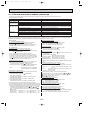
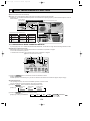
SPLIT-TYPE, HEAT PUMP AIR CONDITIONERS
February 2008
No.OC374
REVISED EDITION-C
SERVICE MANUAL
R410A
Outdoor unit
[model names]
PUHZ-RP35VHA2
PUHZ-RP50VHA2
PUHZ-RP60VHA2
PUHZ-RP71VHA2
PUHZ-RP100VHA2
PUHZ-RP125VHA2
PUHZ-RP140VHA2
PUHZ-RP100YHA2
PUHZ-RP125YHA2
PUHZ-RP140YHA2
Revision:
• PUHZ-RP35/50/60/71/100VHA3
and PUHZ-RP100YHA3 are
added in REVISED EDITIONC.
• Some descriptions have been
modified.
PUHZ-RP35VHA3
PUHZ-RP50VHA3
PUHZ-RP60VHA3
PUHZ-RP71VHA3
PUHZ-RP100VHA3
• Please void OC374 REVISED
EDITION-B.
NOTE:
• This manual describes only
service data of the outdoor
units.
PUHZ-RP100YHA3
• RoHS compliant products have
<G> mark on the spec name
plate.
• For servicing of RoHS compliant products, refer to the RoHS
PARTS LIST.
[Service Ref.]
Service Ref. is on page 2.
CONTENTS
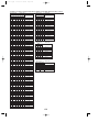
1. TECHNICAL CHANGES·································3
2. REFERENCE MANUAL··································4
3. SAFETY PRECAUTION··································5
4. FEATURES ·····················································9
5. SPECIFICATIONS·········································10
6. DATA ·····························································13
7. OUTLINES AND DIMENSIONS····················20
8. WIRING DIAGRAM ·······································25
9. WIRING SPECIFICATIONS ··························32
10. REFRIGERANT SYSTEM DIAGRAM··············37
11. TROUBLESHOOTING···································40
12. FUNCTION SETTING··································107
13. MONITORING THE OPERATION DATA BY THE REMOTE CONTROLLER······114
14. EASY MAINTENANCE FUNCTION ············124
15. DISASSEMBLY PROCEDURE ···················129
16. PARTS LIST ················································151
17. RoHS PARTS LIST ·····································162
PUHZ-RP60VHA2 PUHZ-RP60VHA21
PUHZ-RP71VHA2 PUHZ-RP71VHA21
PUHZ-RP60VHA3 PUHZ-RP71VHA3
OC374C--1.qxp
08.2.22 8:18 AM
Page 2
[Service Ref.]
PUHZ-RP35VHA2
PUHZ-RP35VHA21
PUHZ-RP50VHA2
PUHZ-RP50VHA21
PUHZ-RP60VHA2
PUHZ-RP60VHA21
PUHZ-RP71VHA2
PUHZ-RP71VHA21
PUHZ-RP100VHA2
PUHZ-RP100VHA21
PUHZ-RP125VHA2
PUHZ-RP125VHA21
PUHZ-RP140VHA2
PUHZ-RP140VHA21
PUHZ-RP100YHA2
PUHZ-RP100YHA21
PUHZ-RP125YHA2
PUHZ-RP125YHA21
PUHZ-RP140YHA2
PUHZ-RP140YHA21
PUHZ-RP35VHA3
PUHZ-RP50VHA3
PUHZ-RP60VHA3
PUHZ-RP71VHA3
PUHZ-RP100VHA3
PUHZ-RP100YHA3
2
OC374C--1.qxp
1
08.2.22 8:18 AM
Page 3
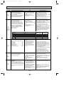
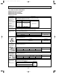
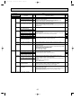
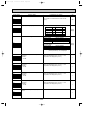
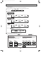
TECHNICAL CHANGES
PUHZ-RP35/50VHA21
PUHZ-RP35/50VHA3
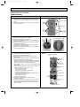
· Muffler has been changed.
· Compressor (MC) has been changed.
· Controller circuit board(C.B.) and power circuit board(P.B.) have been changed.
PUHZ-RP60/71VHA21
·
·
·
·
PUHZ-RP60/71VHA3
Compressor (MC) and oil(type and amount) have been changed.
Refigerant circiuit has been changed.
Ball valve(Gas)
Stop valve
Controller circuit board(C.B.) has been changed.
PUHZ-RP100VHA21
PUHZ-RP100VHA3
· Compressor (MC) has been changed.
· Controller circuit board(C.B.) and power circuit board(P.B.) have been changed.
PUHZ-RP100YHA21
PUHZ-RP100YHA3
· Compressor (MC) has been changed.
· Controller circuit board(C.B.) has been changed.
PUHZ-RP35/50/60/71VHA2
PUHZ-RP35/50/60/71VHA21
· Electrical parts have been changed.
Controller circuit board (C.B.) , Power circuit board (P.B.) , Noise filter circuit board (N.F.)
PUHZ-RP100/125/140VHA2
PUHZ-RP100/125/140VHA21
· Compressor (MC) has been changed.
· Electrical parts have been changed.
Controller circuit board (C.B.) , Power circuit board (P.B.) , Noise filter circuit board (N.F.) , Active filter module (ACTM)
PUHZ-RP100/125/140YHA2
PUHZ-RP100/125/140YHA21
· Compressor (MC) has been changed.
· Electrical parts have been changed.
Controller circuit board (C.B.) , Power circuit board (P.B.) , Noise filter circuit board (N.F.)
3
OC374C--1.qxp
2
08.2.22 8:18 AM
Page 4
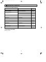
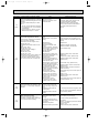
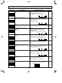
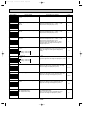
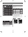
REFERENCE MANUAL
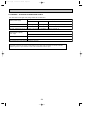
2-1. INDOOR UNIT SERVICE MANUAL
Model name
Service Ref.
PLA-RP35/50/60/71/100/125/140BA
PLA-RP71/100/125BA2
PLA-RP35/50/60/71/100/125/140BA.UK
PLA-RP71/100/125BA2.UK
Service
Manual No.
OCH412
OCB412
PLA-RP35/50/60/71AA.UK
OC335
PLA-RP35/50/60/71AA
OC327
PLA-RP35/50/60/71AA
PLA-RP100/125/140AA2
PLA-RP100/125/140AA2.UK
PCA-RP50/60/71/100/125/140GA
PCA-RP50GA2
PCA-RP50/60/71/100/125/140GA
PCA-RP50GA2
PCA-RP71/125HA
PCA-RP71/125HA
PKA-RP35/50GAL
PKA-RP35/50GAL
PKA-RP60/71/100FAL
PKA-RP50FAL2
PKA-RP60/71/100FAL
PKA-RP50FAL2
PSA-RP71/100/125/140GA
PSA-RP71/100/125/140GA
PEAD-RP50/60/71/125/140EA
PEAD-RP35/100EA2
PEAD-RP60/71/100GA
PEAD-RP50/60/71/125/140EA.UK
PEAD-RP35/100EA2.UK
PEAD-RP60/71/100GA.UK
2-2.TECHNICAL DATA BOOK
Manual No. OCS05
4
OC357
OC328
OC329
OC330
OC331
OC332
HWE05210
HWE05060
OC374C--1.qxp
08.2.22 8:18 AM
3
Page 5
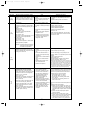
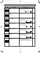
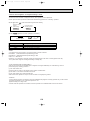
SAFETY PRECAUTION
3-1. ALWAYS OBSERVE FOR SAFETY
Before obtaining access to termnal, all supply
ciucuits must disconnected.
3-2. CAUTIONS RELATED TO NEW REFRIGERANT
Cautions for units utilizing refrigerant R410A
Use new refrigerant pipes.
Do not use refrigerant other than R410A.
In case of using the existing pipes for R22, be careful with
the followings.
· For RP60/71VHA3 and RP100/125/140, be sure to
perform replacement operation before test run.
· Change flare nut to the one provided with this product.
Use a newly flared pipe.
· Avoid using thin pipes.
If other refrigerant (R22 etc.) is used, chlorine in refrigerant can cause deterioration of refrigerant oil etc.
Use a vacuum pump with a reverse flow check
valve.
Vacuum pump oil may flow back into refrigerant cycle and
that can cause deterioration of refrigerant oil etc.
Make sure that the inside and outside of refrigerant piping is clean and it has no contamination
such as sulfur hazardous for use, oxides, dirt,
shaving particles, etc.
In addition, use pipes with specified thickness.
Use the following tools specifically designed for
use with R410A refrigerant.
The following tools are necessary to use R410A refrigerant.
Gauge manifold
Charge hose
Gas leak detector
Torque wrench
Contamination inside refrigerant piping can cause deterioration of refrigerant oil etc.
Tools for R410A
Flare tool
Size adjustment gauge
Vacuum pump adaptor
Electronic refrigerant
charging scale
Store the piping to be used during installation
indoors and keep both ends of the piping sealed
until just before brazing. (Leave elbow joints, etc.
in their packaging.)
Keep the tools with care.
If dirt, dust or moisture enters into refrigerant cycle, that can
cause deterioration of refrigerant oil or malfunction of compressor.
If dirt, dust or moisture enters into refrigerant cycle, that can
cause deterioration of refrigerant oil or malfunction of compressor.
Use ester oil, ether oil or alkylbenzene oil (small
amount) as the refrigerant oil applied to flares
and flange connections.
Do not use a charging cylinder.
If large amount of mineral oil enters, that can cause deterioration of refrigerant oil etc.
If a charging cylinder is used, the composition of refrigerant will change and the efficiency will be lowered.
Ventilate the room if refrigerant leaks during
operation. If refrigerant comes into contact with
a flame, poisonous gases will be released.
Charge refrigerant from liquid phase of gas
cylinder.
If the refrigerant is charged from gas phase, composition
change may occur in refrigerant and the efficiency will be
lowered.
[1] Cautions for service
(1) Perform service after recovering the refrigerant left in unit completely.
(2) Do not release refrigerant in the air.
(3) After completing service, charge the cycle with specified amount of refrigerant.
(4) When performing service, install a filter drier simultaneously.
Be sure to use a filter drier for new refrigerant.
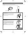
[2] Additional refrigerant charge
When charging directly from cylinder
· Check that cylinder for R410A on the market is syphon type.
· Charging should be performed with the cylinder of syphon stood vertically. (Refrigerant is charged from liquid phase.)
5
OC374C--1.qxp
08.2.22 8:18 AM
Page 6
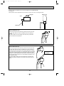
Unit
Gravimeter
[3] Service tools
Use the below service tools as exclusive tools for R410A refrigerant.
No.
1
Tool name
Gauge manifold
Specifications
·Only for R410A
·Use the existing fitting specifications. (UNF1/2)
·Use high-tension side pressure of 5.3MPa·G or over.
2
Charge hose
3
Electronic scale
4
Gas leak detector
·Use the detector for R134a, R407C or R410A.
5
Adaptor for reverse flow check
·Attach on vacuum pump.
6
Refrigerant charge base
7
Refrigerant cylinder
8
Refrigerant recovery equipment
·Only for R410A
·Use pressure performance of 5.09MPa·G or over.
·Only for R410A
·Top of cylinder (Pink)
·Cylinder with syphon
[4] Refrigerant leakage detection function
This air conditioner (outdoor unit PUHZ-RP•HA2/HA3) can detect refrigerant leakage which may happen during a long
period of use. In order to enable the leakage detection, settings are required to let the unit memorize the initial
conditions(initial learning). Refer to 14-3. INITIAL SETTINGS FOR REFRIGERANT LEAKAGE DETECTION FUNCTION.
6
OC374C--1.qxp
08.2.22 8:18 AM
Page 7
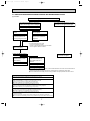
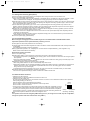
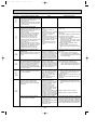
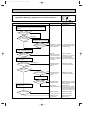
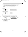
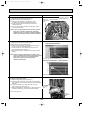
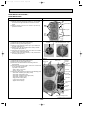
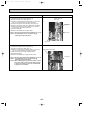
3-3. PRECAUTIONS WHEN REUSING EXISTING R22 REFRIGERANT PIPES
(1) Flowchart
Measure the existing pipe thickness and check for damage.
The existing pipe thickness meets specifications and the pipes are not damaged.
The existing pipe thickness does not meet
specifications or the pipes are damaged.
Check if existing air conditioner can operate.
Existing air conditioner can
operate.
Existing air conditioner
cannot operate.
Perform cooling operation
for about 30 minutes and
then do a pump down work.
Use a refrigerant recovery
equipment to recover the
refrigerant.
w In case existing pipes were used
Disconnect existing air conditioner from piping.
for gas or oil heat pump system,
be sure to clean the pipes for RP100-140 models.
Use new pipes for RP35-71 models.
Existing pipes can be reused.
In case the unit is RP35/50
or RP60/71VHA2(1) which
utilizes HAB oil.
Existing pipes cannot be
reused. Use new pipes.
In case the unit is RP60/71
VHA3 or RP100/125/140
which utilize ester oil or
ether oil.
Connect a new air conditioner.
Connect a new air conditioner.
Perform replacement operation.
·When performing replacement operation, make sure that DIP SW8-2 on outdoor unit controller board is
set to ON.
wChemical compounds containing chlorine left in existing pipes are collected by replace filter.
●The air conditioner automatically performs cooling operation through replace filter for about 2 hours.
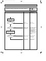
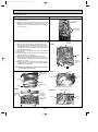
Connecting a new air conditioner
1Flaring work should be done so that flare meets the dimension for R410A.
Use flare nut provided with indoor and outdoor unit.
2When using gas piping of [19.05mm for RP100, 125 or 140.
Make sure that DIP SW8-1 on outdoor unit controller board is set to ON.
WThis is to keep the pressure on pipes within permissible range.
●Use different diameter joint or adjust the piping size by brazing.
3When using pipes larger than specified size for RP35, 50, 60 or 71.
Make sure that DIP SW8-1 on outdoor unit controller board is set to ON.
WThis is to prevent oil flow ratio from lowering due to the decrease in flowing refrigerant.
●Use different diameter joint or adjust the piping size by brazing.
4When existing pipes are specified size.
The pipes can be reused referring to TECHNICAL DATA BOOK (OCS05).
●Use different diameter joint or adjust the piping size by brazing.
★When using existing pipes for RP60/71VHA3 and RP100/125/140
Make sure that DIP SW8-2 on outdoor unit controller board is set to ON and perform
replacement operation.
wChemical compounds containing chlorine left in existing pipes are collected by replace filter.
●The air conditioner automatically performs cooling operation through replace filter for about 2 hours.
7
OC374C--1.qxp
08.2.22 8:18 AM
Page 8
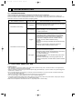
(2) Cautions for refrigerant piping work
New refrigerant R410A is adopted for replacement inverter series. Although the refrigerant piping work for R410A is same
as for R22, exclusive tools are necessary so as not to mix with different kind of refrigerant. Furthermore as the working
pressure of R410A is 1.6 time higher than that of R22, their sizes of flared sections and flare nuts are different.
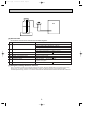
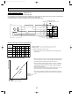
1Thickness of pipes
Because the working pressure of R410A is higher compared to R22, be sure to use refrigerant piping with thickness
shown below. (Never use pipes of 0.7mm or below.)
Diagram below: Piping diameter and thickness
Thickness (mm)
Nominal
Outside
dimensions(inch) diameter (mm)
R410A
R22
1/4
6.35
0.8
0.8
3/8
9.52
0.8
0.8
1/2
12.70
0.8
0.8
5/8
15.88
1.0
1.0
—
3/4
19.05
1.0
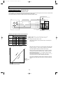
2Dimensions of flare cutting and flare nut
The component molecules in HFC refrigerant are smaller compared to conventional refrigerants. In addition to that,
R410A is a refrigerant, which has higher risk of leakage because its working pressure is higher than that of other refrigerants. Therefore, to enhance airtightness and intensity, flare cutting dimension of copper pipe for R410A have been specified separately from the dimensions for other refrigerants as shown below. The dimension B of flare nut for R410A also
have partly been changed to increase intensity as shown below. Set copper pipe correctly referring to copper pipe flaring
dimensions for R410A below. For 1/2 and 5/8 inch, the dimension B changes.
Use torque wrench corresponding to each dimension.
Dimension A
Dimension B
Flare cutting dimensions
Nominal
Outside
dimensions(inch)
diameter
1/4
6.35
3/8
9.52
1/2
12.70
5/8
15.88
3/4
19.05
(mm)
Dimension A ( +0
-0.4 )
R410A
R22
9.1
9.0
13.2
13.0
16.6
16.2
19.7
19.4
—
23.3
Flare nut dimensions
Nominal
Outside
dimensions(inch)
diameter
1/4
6.35
3/8
9.52
1/2
12.70
5/8
15.88
3/4
19.05
(mm)
Dimension B
R410A
R22
17.0
17.0
22.0
22.0
w36.0mm for
26.0
24.0
indoor unit
29.0 w
27.0
of RP100,
—
36.0
125 and 140
3Tools for R410A (The following table shows whether conventional tools can be used or not.)
Tools and materials
Gauge manifold
Charge hose
Gas leak detector
Refrigerant recovery equipment
Refrigerant cylinder
Applied oil
Use
Air purge, refrigerant charge
and operation check
Gas leak check
Refrigerant recovery
Refrigerant charge
Apply to flared section
R410A tools
Can R22 tools be used? Can R407C tools be used?
Tool exclusive for R410A
Tool exclusive for R410A
Tool for HFC refrigerant
Tool exclusive for R410A
Tool exclusive for R410A
Ester oil and alkylbenzene
Ester oil:
Alkylbenzene oil: minimum amount
oil (minimum amount)
Prevent compressor malfunction Tool exclusive for R410A
Safety charger
when charging refrigerant by
spraying liquid refrigerant
Prevent gas from blowing out Tool exclusive for R410A
Charge valve
when detaching charge hose
Vacuum drying and air
Vacuum pump
Tools for other refrigerants can
(Usable if equipped
(Usable if equipped
with adopter for reverwith adopter for reverpurge
be used if equipped with adopse flow)
se flow)
ter for reverse flow check
Flaring work of piping
Tools for other refrigerants
Flare tool
(Usable by adjusting
(Usable by adjusting
can be used by adjusting
flaring dimension)
flaring dimension)
flaring dimension
Bend the pipes
Tools for other refrigerants can be used
Bender
Tools for other refrigerants can be used
Cut the pipes
Pipe cutter
Tools for other refrigerants can be used
Welder and nitrogen gas cylinder Weld the pipes
Tools for other refrigerants can be used
Refrigerant charging scale Refrigerant charge
Vacuum gauge or thermis- Check the degree of vacuum. (Vacuum Tools for other refrigerants
valve prevents back flow of oil and refri- can be used
tor vacuum gauge and
gerant to thermistor vacuum gauge)
vacuum valve
Refrigerant charge
Charging cylinder
Tool exclusive for R410A
: Prepare a new tool. (Use the new tool as the tool exclusive for R410A.)
: Tools for other refrigerants can be used under certain conditions.
: Tools for other refrigerants can be used.
8
OC374C--1.qxp
08.2.22 8:18 AM
4
Page 9
FEATURES
PUHZ-RP35/ 50VHA2
PUHZ-RP35/ 50VHA21
PUHZ-RP35/ 50VHA3
PUHZ-RP60/ 71VHA2
PUHZ-RP60/ 71VHA21
PUHZ-RP60/ 71VHA3
PUHZ-RP100/ 125/ 140VHA2
PUHZ-RP100/ 125/ 140VHA21
PUHZ-RP100/ 125/ 140YHA2
PUHZ-RP100/ 125/ 140YHA21
PUHZ-RP100VHA3
PUHZ-RP100YHA3
CHARGELESS SYSTEM
PRE-CHARGED REFRIGERANT IS SUPPLIED FOR PIPING LENGTH AT SHIPMENT.
Max.30m(PUHZ-RP35/50/60/71/100/125/140)
The refrigerant circuit with LEV(Linear Expansion Valve) and power receiver always control the optimal refrigerant
level regardless of the length (30m max. and 5m min.) of piping. The additional refrigerant charging work during
installation often causes problems. It is completely eliminated by chargelss system. This unique system improves the quality
and reliability of the work done. It also helps to speed up the installation time.
REFRIGERANT LEAKAGE DETECTION FUNCTION
PUHZ-RP•HA2(1)/HA3 can detect refrigerant leakage which may happen during a long period of use.
9
OC374C--1.qxp
5
08.2.22 8:18 AM
Page 10
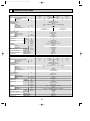
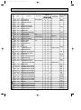
SPECIFICATIONS
PUHZ-RP35VHA2(1) / VHA3
Cooling
OUTDOOR UNIT
Service Ref.
Mode
Power supply (phase, cycle, voltage)
Running current
Max. current
External finish
Refrigerant control
Compressor
Model
Motor output
Starter type
Protection devices
Crankcase heater
Heat exchanger
Fan
Fan(drive) o No.
Fan motor output
Airflow
Defrost method
Noise level
REFRIGERANT PIPING
Dimensions
Weight
Refrigerant
Charge
Oil (Model)
Pipe size O.D.
Connection method
Between the indoor &
outdoor unit
A
A
HP switch
Discharge thermo
kg(lbs)
L
mm(in.)
mm(in.)
Liquid
Gas
Indoor side
Outdoor side
Height difference
Piping length
OUTDOOR UNIT
REFRIGERANT PIPING
Dimensions
Weight
Refrigerant
Charge
Oil (Model)
Pipe size O.D.
Connection method
Between the indoor &
outdoor unit
kW
PUHZ-RP71VHA2(1) / VHA3
PUHZ-RP60VHA2(1) / VHA3
Cooling
Heating
Heating
Cooling
Single, 50Hz, 230V
6.61
7.50
9.74
8.04
19
Munsell 3Y 7.8/1.1
Linear Expansion Valve
Hermetic
VHA2(1) : TNB220FMBH / VHA3 : SNB172FDGM1
1.4
1.6
Inverter
HP switch
Discharge thermo
—
Plate fin coil
Propeller fan o 1
0.060
55(1,940)
Reverse cycle
47
48
950(37-3/8)
330+30(13+1-3/16)
943(37-1/8)
VHA2(1) : 75(165) / VHA3 : 68(150)
R410A
3.5(7.7)
VHA2(1) : 0.87(NEO22) / VHA3 : 0.70(FV50S)
9.52(3/8)
15.88(5/8)
Flared
Flared
Max. 30m
Max. 50m
W
kW
K/min(CFM)
Cooling
Heating
W
D
H
HP switch
Discharge thermo
—
Plate fin coil
Propeller fan o 1
0.043
35(1,240)
Reverse cycle
44
46
800(31-1/2)
300+23(11-13/16+7/8)
600(23-5/8)
VHA2(1) : 45(99) / VHA3 : 42(93)
R410A
2.5(5.5)
0.45(NEO22)
6.35(1/4)
12.7(1/2)
Flared
Flared
Max. 30m
Max. 50m
dB
dB
mm(in.)
mm(in.)
mm(in.)
kg(lbs)
A
A
6.47
Munsell 3Y 7.8/1.1
Linear Expansion Valve
Hermetic
VHA2(1) : SNB130FLBH / VHA3 : SNB130FGCH
1.1
0.9
Inverter
kW
K/min(CFM)
Mode
Power supply (phase, cycle, voltage)
Running current
Max. current
External finish
Refrigerant control
Compressor
Model
Motor output
Starter type
Protection devices
Heating
13
13
kW
Service Ref.
Crankcase heater
Heat exchanger
Fan
Fan(drive) o No.
Fan motor output
Airflow
Defrost method
Noise level
4.01
W
Cooling
Heating
W
D
H
PUHZ-RP50VHA2(1) / VHA3
Heating
Cooling
Single, 50Hz, 230V
4.23
6.16
dB
dB
mm(in.)
mm(in.)
mm(in.)
kg(lbs)
kg(lbs)
L
mm(in.)
mm(in.)
Liquid
Gas
Indoor side
Outdoor side
Height difference
Piping length
10
OC374C--1.qxp
08.2.22 8:18 AM
Page 11
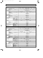
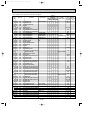
PUHZ-RP100VHA2
Service Ref.
OUTDOOR UNIT
Mode
Power supply (phase, cycle, voltage)
Running current
Max. current
External finish
Refrigerant control
Compressor
Model
Motor output
Starter type
Protection devices
Crankcase heater
Heat exchanger
Fan
Fan(drive) o No.
Fan motor output
Airflow
Defrost method
Noise level
Dimensions
REFRIGERANT PIPING
Between the indoor &
outdoor unit
Cooling
Heating
W
D
H
ANV33FDDMT
1.9
Crankcase heater
Heat exchanger
Fan
Fan(drive) o No.
Fan motor output
Airflow
Defrost method
Noise level
Dimensions
Weight
Refrigerant
Charge
Oil (Model)
Pipe size O.D.
Connection method
Between the indoor &
outdoor unit
19.65
19.92
Munsell 3Y 7.8/1.1
Linear Expansion Valve
Hermetic
ANB33FCKMT
2.4
Inverter
d
HP switch
Discharge thermo
2.9
50
52
950(37-3/8)
330+30(13+1-3/16)
1,350(53-1/8)
116(256)
R410A
121(267)
5.0(11.0)
1.40(MEL56)
9.52(3/8)
15.88(5/8)
Flared
Flared
Max. 30m
Max. 75m
Cooling
Heating
4.08
4.03
ANV33FDBMT
1.9
PUHZ-RP125YHA2
PUHZ-RP140YHA2
Heating
Cooling
Heating
Cooling
3phase, 50Hz, 400V
5.20
6.37
6.46
5.04
13
Munsell 3Y 7.8/1.1
Linear Expansion Valve
Hermetic
ANB33FDFMT
2.9
2.4
Inverter
HP switch
Discharge thermo
—
Plate fin coil
Propeller fan o 2
0.060+0.060
100(3,530)
Reverse cycle
W
kW
K/min(CFM)
Cooling
Heating
W
D
H
Heating
29.5
49
51
PUHZ-RP100YHA2
kW
PUHZ-RP140VHA2
Cooling
—
Plate fin coil
Propeller fan o 2
0.060+0.060
100(3,530)
Reverse cycle
L
mm(in.)
Liquid
mm(in.)
Gas
Indoor side
Outdoor side
Height difference
Piping length
A
A
PUHZ-RP125VHA2
Heating
Cooling
Single 50Hz, 230V
15.98
15.53
28
kg(lbs)
Mode
Power supply (phase, cycle, voltage)
Running current
Max. current
External finish
Refrigerant control
Compressor
Model
Motor output
Starter type
Protection devices
OUTDOOR UNIT
12.39
dB
dB
mm(in.)
mm(in.)
mm(in.)
kg(lbs)
Service Ref.
REFRIGERANT PIPING
12.53
kW
K/min(CFM)
Charge
Connection method
kW
Heating
W
Weight
Refrigerant
Oil (Model)
Pipe size O.D.
A
A
Cooling
50
52
49
51
dB
dB
mm(in.)
mm(in.)
mm(in.)
kg(lbs)
950(37-3/8)
330+30(13+1-3/16)
1,350(53-1/8)
130(287)
135(298)
R410A
5.0(11.0)
kg(lbs)
1.40(MEL56)
9.52(3/8)
15.88(5/8)
Flared
Flared
Max. 30m
Max. 75m
L
mm(in.)
Liquid
mm(in.)
Gas
Indoor side
Outdoor side
Height difference
Piping length
11
OC374C--1.qxp
08.2.22 8:18 AM
Page 12
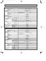
PUHZ-RP100VHA21 / VHA3
Service Ref.
OUTDOOR UNIT
Mode
Power supply (phase, cycle, voltage)
Running current
Max. current
External finish
Refrigerant control
Compressor
Model
Motor output
Starter type
Protection devices
Crankcase heater
Heat exchanger
Fan
Fan(drive) o No.
Fan motor output
Airflow
Defrost method
Noise level
Dimensions
kW
REFRIGERANT PIPING
Between the indoor &
outdoor unit
Cooling
Heating
W
D
H
dB
dB
mm(in.)
mm(in.)
mm(in.)
kg(lbs)
ANV33FDJMT(VHA2(1))
ANB33FCNMT(VHA3)
1.9
Motor output
Starter type
Protection devices
Crankcase heater
Heat exchanger
Fan
Fan(drive) o No.
Fan motor output
Airflow
Defrost method
Noise level
Dimensions
Weight
Refrigerant
Charge
Oil (Model)
Pipe size O.D.
Connection method
Between the indoor &
outdoor unit
kW
VHA21:121(267) / VHA3:116(256)
19.92
Munsell 3Y 7.8/1.1
Linear Expansion Valve
Hermetic
ANB33FCNMT
2.9
2.4
Inverter
HP switch
Discharge thermo
—
Plate fin coil
Propeller fan o 2
0.060+0.060
100(3,530)
Reverse cycle
950(37-3/8)
330+30(13+1-3/16)
1,350(53-1/8)
116(256)
R410A
5.0(11.0)
1.40(FV50S)
9.52(3/8)
15.88(5/8)
Flared
Flared
Max. 30m
Max. 75m
Cooling
Heating
4.08
4.03
ANV33FDGMT(YHA21)
ANB33FDLMT(YHA3)
1.9
kW
K/min(CFM)
dB
dB
mm(in.)
mm(in.)
mm(in.)
kg(lbs)
19.65
50
52
W
Cooling
Heating
W
D
H
Heating
29.5
49
51
PUHZ-RP100YHA21 / YHA3
A
A
PUHZ-RP140VHA21
Cooling
28
L
mm(in.)
Liquid
mm(in.)
Gas
Indoor side
Outdoor side
Height difference
Piping length
Mode
Power supply (phase, cycle, voltage)
Running current
Max. current
External finish
Refrigerant control
Compressor
Model
OUTDOOR UNIT
12.39
kg(lbs)
Service Ref.
REFRIGERANT PIPING
12.53
PUHZ-RP125VHA21
Heating
Cooling
Single 50Hz, 230V
15.98
15.53
kW
K/min(CFM)
Charge
Connection method
Heating
W
Weight
Refrigerant
Oil (Model)
Pipe size O.D.
A
A
Cooling
PUHZ-RP125YHA21
PUHZ-RP140YHA21
Heating
Cooling
Cooling
3phase, 50Hz, 400V
5.20
6.37
5.04
13
Munsell 3Y 7.8/1.1
Linear Expansion Valve
Hermetic
ANB33FDLMT
50
52
950(37-3/8)
330+30(13+1-3/16)
1,350(53-1/8)
130(287)
YHA21:135(298) / YHA3:130(287)
R410A
5.0(11.0)
kg(lbs)
1.40(FV50S)
9.52(3/8)
15.88(5/8)
Flared
Flared
Max. 30m
Max. 75m
L
mm(in.)
Liquid
mm(in.)
Gas
Indoor side
Outdoor side
Height difference
Piping length
12
6.46
2.9
2.4
Inverter
HP switch
Discharge thermo
—
Plate fin coil
Propeller fan o 2
0.060+0.060
100(3,530)
Reverse cycle
49
51
Heating
OC374C--1.qxp
08.2.22 8:18 AM
6
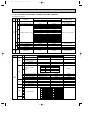
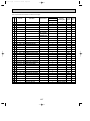
Page 13
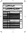
DATA
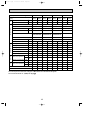
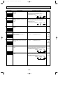
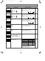
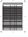
6-1. REFILLING REFRIGERANT CHARGE (R410A : kg)
Service Ref.
PUHZ-RP35VHA2(1)
PUHZ-RP35VHA3
PUHZ-RP50VHA2(1)
PUHZ-RP50VHA3
PUHZ-RP60VHA2(1)
PUHZ-RP60VHA3
PUHZ-RP71VHA2(1)
PUHZ-RP71VHA3
PUHZ-RP100VHA2(1)
PUHZ-RP100VHA3
PUHZ-RP100YHA2(1)
PUHZ-RP100YHA3
PUHZ-RP125VHA2
PUHZ-RP125VHA21
PUHZ-RP125YHA2
PUHZ-RP125YHA21
PUHZ-RP140VHA2
PUHZ-RP140VHA21
PUHZ-RP140YHA2
PUHZ-RP140YHA21
10m
20m
Piping length (one way)
30m
40m
50m
2.1
2.3
2.5
2.7
2.1
2.3
2.5
3.1
3.3
3.1
60m
75m
Initial
charged
2.9
—
—
2.5
2.7
2.9
—
—
2.5
3.5
4.1
4.7
—
—
3.5
3.3
3.5
4.1
4.7
—
—
3.5
4.6
4.8
5.0
5.6
6.2
6.8
7.4
5.0
4.6
4.8
5.0
5.6
6.2
6.8
7.4
5.0
4.6
4.8
5.0
5.6
6.2
6.8
7.4
5.0
Longer pipe than 30m, additional charge is
required.
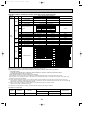
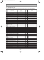
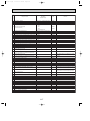
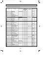
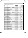
6-2. COMPRESSOR TECHNICAL DATA
(at 20°C)
Serice Ref.
PUHZ-RP35/50VHA2 PUHZ-RP60/71VHA2 PUHZ-RP100VHA2 PUHZ-RP125/140VHA2 PUHZ-RP100YHA2 PUHZ-RP125/140YHA2
PUHZ-RP35/50VHA21 PUHZ-RP60/71VHA21
Compressor model SNB130FLBH
TNB220FMBH
ANV33FDDMT
ANB33FCKMT
ANV33FDBMT
ANB33FDFMT
U-V
Winding
Resistance U-W
(")
W-V
0.300 ~ 0.340
0.865 ~ 0.895
0.266
0.188
1.064
0.302
0.300 ~ 0.340
0.865 ~ 0.895
0.266
0.188
1.064
0.302
0.300 ~ 0.340
0.865 ~ 0.895
0.266
0.188
1.064
0.302
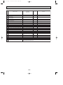
(at 20°C)
PUHZ-RP100VHA21
PUHZ-RP125/140VHA21
PUHZ-RP100VHA3
PUHZ-RP100YHA21
PUHZ-RP125/140YHA21
PUHZ-RP100YHA3
Compressor model
ANV33FDJMT
ANB33FCNMT
ANV33FDGMT
ANB33FDLMT
U-V
Winding
Resistance U-W
(")
W-V
0.266
0.302
1.064
0.302
0.266
0.302
1.064
0.302
0.266
0.302
1.064
0.302
Serice Ref.
(at 20°C)
Serice Ref.
PUHZ-RP35/50VHA3
PUHZ-RP60/71VHA3
Compressor model
SNB130FGCH
SNB172FDGM1
U-V
Winding
Resistance U-W
(")
W-V
0.64
0.72
0.64
0.72
0.64
0.72
13
OC374C--1.qxp
08.2.22 8:18 AM
Page 14
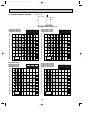
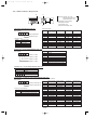
6-3. NOISE CRITERION CURVES
MICROPHONE
1m
UNIT
1.5m
GROUND
90
80
70
NC-70
60
NC-60
50
NC-50
40
NC-40
30
NC-30
20
10
APPROXIMATE
THRESHOLD OF
HEARING FOR
CONTINUOUS
NOISE
63
NC-20
125
250
500 1000 2000 4000
BAND CENTER FREQUENCIES, Hz
PUHZ-RP100VHA2(1)
PUHZ-RP100VHA3
PUHZ-RP100YHA2(1)
PUHZ-RP100YHA3
OCTAVE BAND SOUND PRESSURE LEVEL, dB (0 dB = 0.0002 µbar)
LINE
MODE SPL(dB)
COOLING
49
HEATING
51
LINE
80
NC-70
60
NC-60
50
NC-50
40
NC-40
30
NC-30
20
10
APPROXIMATE
THRESHOLD OF
HEARING FOR
CONTINUOUS
NOISE
63
125
NC-20
250
500
1000
2000
4000
8000
MODE SPL(dB)
COOLING
47
HEATING
48
LINE
90
80
70
NC-70
60
NC-60
50
NC-50
40
NC-40
30
NC-30
20
10
8000
90
70
PUHZ-RP60/71VHA2
PUHZ-RP60/71VHA21
PUHZ-RP60/71VHA3
OCTAVE BAND SOUND PRESSURE LEVEL, dB (0 dB = 0.0002 µbar)
MODE SPL(dB)
COOLING
44
HEATING
46
APPROXIMATE
THRESHOLD OF
HEARING FOR
CONTINUOUS
NOISE
63
NC-20
125
250
500 1000 2000 4000
BAND CENTER FREQUENCIES, Hz
PUHZ-RP125/140VHA2
PUHZ-RP125/140VHA21
PUHZ-RP125/140YHA2
PUHZ-RP125/140YHA21
OCTAVE BAND SOUND PRESSURE LEVEL, dB (0 dB = 0.0002 µbar)
OCTAVE BAND SOUND PRESSURE LEVEL, dB (0 dB = 0.0002 µbar)
PUHZ-RP35/50VHA2
PUHZ-RP35/50VHA21
PUHZ-RP35/50VHA3
MODE SPL(dB)
COOLING
50
HEATING
52
8000
LINE
90
80
70
NC-70
60
NC-60
50
NC-50
40
NC-40
30
NC-30
20
10
BAND CENTER FREQUENCIES, Hz
APPROXIMATE
THRESHOLD OF
HEARING FOR
CONTINUOUS
NOISE
63
125
NC-20
250
500
1000
2000
4000
BAND CENTER FREQUENCIES, Hz
14
8000
OC374C--1.qxp
08.2.22 8:18 AM
Page 15
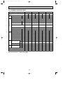
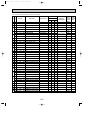
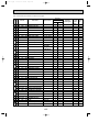
6-4. STANDARD OPERATION DATA
PLA-RP35AA
Representative matching
Electrical circuit
Total
Mode
Refrigerant circuit
PLA-RP60AA
PLA-RP71AA
Cooling
Heating
Cooling
Heating
Cooling
Heating
Cooling
Heating
Capacity
W
3,600
4,100
5,000
6,000
6,000
7,000
7,100
8,000
Input
kW
1.07
1.12
1.55
1.62
1.65
1.85
1.97
2.34
Indoor unit
PLA-RP35AA
PLA-RP50AA
PLA-RP60AA
PLA-RP71AA
Phase , Hz
1 , 50
1 , 50
1 , 50
1 , 50
Voltage
V
230
230
230
230
Current
A
0.79
0.79
0.79
0.79
Outdoor unit
PUHZ-RP35VHA2 PUHZ-RP50VHA2 PUHZ-RP60VHA2 PUHZ-RP71VHA2
Phase , Hz
Outdoor Indoor side
side
PLA-RP50AA
1 , 50
1 , 50
1 , 50
1 , 50
230
230
230
230
Voltage
V
Current
A
4.01
4.23
6.16
6.47
6.61
7.50
8.04
9.74
Discharge pressure
MPa
2.70
2.69
2.91
2.76
2.60
2.63
2.68
2.87
Suction pressure
MPa
1.01
0.74
0.99
0.67
0.99
0.70
0.94
0.73
Discharge temperature
°C
70
71
73
77
65
81
70
74
Condensing temperature
°C
46
41
49
44
44
44
46
48
Suction temperature
°C
15
2
11
-1
12
8
10
1
Ref. pipe length
m
5
5
5
5
5
5
5
5
D.B.
°C
27
20
27
20
27
20
27
20
W.B.
°C
19
15
19
15
19
15
19
15
D.B.
°C
15.6
35.5
15.4
37.8
14.3
40.9
14.2
41.6
D.B.
°C
35
7
35
7
35
7
35
7
W.B.
°C
24
6
24
6
24
6
24
6
SHF
0.89
—
0.86
—
0.78
—
0.74
—
BF
0.11
—
0.14
—
0.14
—
0.18
—
Intake air temperature
Discharge air temperature
Intake air temperature
The unit of pressure has been changed to MPa based on international SI system.
f)
The conversion factor is : 1(MPa)=10.2(kgf/f
15
OC374C--1.qxp
08.2.22 8:18 AM
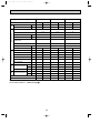
Page 16
PLA-RP100AA2
Representative matching
Electrical circuit
Total
Mode
Refrigerant circuit
PLA-RP140AA2
Cooling
Heating
Cooling
Heating
Cooling
Heating
Capacity
W
10,000
11,200
12,500
14,000
14,000
16,000
Input
kW
3.02
3.02
3.87
3.88
4.65
4.69
Indoor unit
PLA-RP100AA2
PLA-RP125AA2
PLA-RP140AA2
Phase , Hz
1 , 50
1 , 50
1 , 50
Voltage
V
230
230
230
Current
A
0.92
0.92
0.92
PUHZ-RP100VHA2
PUHZ-RP125VHA2
PUHZ-RP140VHA2
1 , 50
1 , 50
1 , 50
230
230
230
Outdoor unit
Phase , Hz
Outdoor Indoor side
side
PLA-RP125AA2
Voltage
V
Current
A
12.53
12.39
15.53
15.98
19.65
19.92
Discharge pressure
MPa
2.55
2.46
2.72
2.73
2.86
2.90
Suction pressure
MPa
0.94
0.70
0.88
0.66
0.81
0.64
Discharge temperature
°C
63
70
69
76
76
83
Condensing temperature
°C
44
42
46
47
48
50
Suction temperature
°C
11
3
9
2
8
1
Ref. pipe length
m
5
5
5
5
5
5
D.B.
°C
27
20
27
20
27
20
W.B.
°C
19
15
19
15
19
15
D.B.
°C
13.0
42.5
12.2
45.5
11.2
49.6
D.B.
°C
35
7
35
7
35
7
W.B.
°C
24
6
24
6
24
6
SHF
0.78
—
0.74
—
0.71
—
BF
0.04
—
0.05
—
0.05
—
Intake air temperature
Discharge air temperature
Intake air temperature
The unit of pressure has been changed to MPa based on international SI system.
f)
The conversion factor is : 1(MPa)=10.2(kgf/f
16
OC374C--1.qxp
08.2.22 8:18 AM
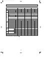
Page 17
PLA-RP100AA2
Representative matching
Electrical circuit
Total
Mode
Refrigerant circuit
PLA-RP140AA2
Cooling
Heating
Cooling
Heating
Cooling
Heating
Capacity
W
10,000
11,200
12,500
14,000
14,000
16,000
Input
kW
3.02
3.02
3.87
3.88
4.65
4.69
Indoor unit
PLA-RP100AA2
PLA-RP125AA2
PLA-RP140AA2
Phase , Hz
1 , 50
1 , 50
1 , 50
Voltage
V
230
230
230
Current
A
0.92
0.92
0.92
PUHZ-RP100YHA2
PUHZ-RP125YHA2
PUHZ-RP140YHA2
3 , 50
3 , 50
3 , 50
400
400
400
Outdoor unit
Phase , Hz
Outdoor Indoor side
side
PLA-RP125AA2
Voltage
V
Current
A
4.08
4.03
5.04
5.20
6.37
6.46
Discharge pressure
MPa
2.55
2.46
2.72
2.73
2.86
2.90
Suction pressure
MPa
0.94
0.70
0.88
0.66
0.81
0.64
Discharge temperature
°C
63
70
69
76
76
83
Condensing temperature
°C
44
42
46
47
48
50
Suction temperature
°C
11
3
9
2
8
1
Ref. pipe length
m
5
5
5
5
5
5
D.B.
°C
27
20
27
20
27
20
W.B.
°C
19
15
19
15
19
15
D.B.
°C
13.0
42.5
12.2
45.5
11.2
49.6
D.B.
°C
35
7
35
7
35
7
W.B.
°C
24
6
24
6
24
6
SHF
0.78
—
0.74
—
0.71
—
BF
0.04
—
0.05
—
0.05
—
Intake air temperature
Discharge air temperature
Intake air temperature
The unit of pressure has been changed to MPa based on international SI system.
f)
The conversion factor is : 1(MPa)=10.2(kgf/f
17
OC374C--1.qxp
08.2.22 8:18 AM
Page 18
PLA-RP35BA
Representative matching
Electrical circuit
Total
Mode
Refrigerant circuit
PLA-RP60BA
PLA-RP71BA2
Cooling
Heating
Cooling
Heating
Cooling
Heating
Cooling
Heating
Capacity
W
3,600
4,100
5,000
6,000
6,000
7,000
7,100
8,000
Input
kW
1.07
1.12
1.55
1.62
1.65
1.85
1.94
1.90
Indoor unit
PLA-RP35BA
PLA-RP50BA
PLA-RP60BA
PLA-RP71BA2
Phase , Hz
1 , 50
1 , 50
1 , 50
1 , 50
Voltage
V
230
230
230
230
Current
A
0.22
0.36
0.36
0.51
Outdoor unit
PUHZ-RP35VHA3 PUHZ-RP50VHA3 PUHZ-RP60VHA3 PUHZ-RP71VHA3
Phase , Hz
Outdoor Indoor side
side
PLA-RP50BA
1 , 50
1 , 50
1 , 50
1 , 50
230
230
230
230
Voltage
V
Current
A
4.01
4.23
6.16
6.47
6.61
7.50
8.04
9.74
Discharge pressure
MPa
2.70
2.69
2.91
2.76
2.60
2.63
2.77
2.51
Suction pressure
MPa
1.01
0.74
0.99
0.67
0.99
0.70
0.99
0.70
Discharge temperature
°C
70
71
73
77
65
81
68
68
Condensing temperature
°C
46
41
49
44
44
44
46
42
Suction temperature
°C
15
2
11
-1
12
8
11
1
Ref. pipe length
m
5
5
5
5
5
5
5
5
D.B.
°C
27
20
27
20
27
20
27
20
W.B.
°C
19
15
19
15
19
15
19
15
D.B.
°C
15.8
34.6
15.3
37.8
14.3
40.8
14.2
40.3
D.B.
°C
35
7
35
7
35
7
35
7
W.B.
°C
24
6
24
6
24
6
24
6
SHF
0.84
—
0.81
—
0.76
—
0.73
—
BF
0.28
—
0.24
—
0.21
—
0.21
—
Intake air temperature
Discharge air temperature
Intake air temperature
The unit of pressure has been changed to MPa based on international SI system.
f)
The conversion factor is : 1(MPa)=10.2(kgf/f
18
OC374C--1.qxp
08.2.22 8:18 AM
Page 19
PLA-RP100BA2
Representative matching
Electrical circuit
Total
Mode
Cooling
Heating
Cooling
Heating
Capacity
W
10,000
11,200
10,000
11,200
Input
kW
2.44
2.54
2.50
2.60
Indoor unit
PLA-RP100BA2
PLA-RP100BA2
Phase , Hz
1 , 50
1 , 50
Voltage
V
230
230
Current
A
1.00
0.92
PUHZ-RP100VHA3
PUHZ-RP100YHA3
1 , 50
3 , 50
230
400
Outdoor unit
Refrigerant circuit
Phase , Hz
Outdoor Indoor side
side
PLA-RP100BA2
Voltage
V
Current
A
12.53
12.39
4.08
4.03
Discharge pressure
MPa
2.55
2.58
2.55
2.58
Suction pressure
MPa
0.95
0.71
0.95
0.71
Discharge temperature
°C
66
74
66
74
Condensing temperature
°C
43
43
43
43
Suction temperature
°C
13
5
13
5
Ref. pipe length
m
5
5
5
5
D.B.
°C
27
20
27
20
W.B.
°C
19
15
19
15
D.B.
°C
13.5
40.0
13.5
40.0
D.B.
°C
35
7
35
7
W.B.
°C
24
6
24
6
SHF
0.74
—
0.74
—
BF
0.21
—
0.21
—
Intake air temperature
Discharge air temperature
Intake air temperature
The unit of pressure has been changed to MPa based on international SI system.
f)
The conversion factor is : 1(MPa)=10.2(kgf/f
19
OC374C--1.qxp
08.2.22 8:18 AM
7
Page 20
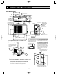
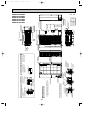
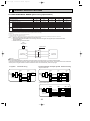
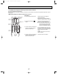
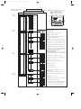
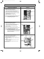
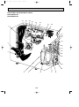
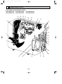
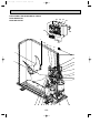
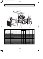
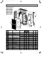
OUTLINES AND DIMENSIONS
Unit : mm
PUHZ-RP35/50VHA2(1)
PUHZ-RP35/50VHA3
400
[33 drain hole
347.5
330
300
Air intake
[33 drain hole
365
155
152
43.6
Air intake
45.4
40
18
23
32.5
4-10 o 21 oval hole
(M10 foundation bolt)
Service panel
Service panel
for charge plug
Air discharge
Handle for
moving
150
43
Connection for
gas pipe
90
10
155
300
35
600
Connection for
liquid pipe
183
69
287.5
Service port
Installation bolt pitch: 500
800
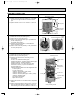
1. FOUNDATION BOLTS
100
mm
Piping and wiring connection can
be made from the rear direction only.
3. ATTACHING THE CONDUIT
<Foundation bolt height>
w1
18 or below
Basically open
Free space around the outdoor unit
(basic example)
100 mm or more as long as
no obstacle is placed on the
rear and right-and-left sides
of the unit.
2. PIPING-WIRING DIRECTION
Please secure the unit firmly
with 4 foundation (M10) bolts.
(Bolts, washer and nut must
be purchased locally.)
ore
m
00 m
or m
1
In order to attach the conduit, it is
necessary to fix the metal plate with
2 screws to the back panel. Procure
the metal plate and make screw holes
locally. It is recommended to use the
metal plate shown below. Align the
metal plate to the marks on the unit
and attach it.
FOUNDATION
or m
ore
w1
w2
ore
m
0m
50
or m
350
mm
40
w The position and the size of
conduit hole depend on the
conduit to be used.
20
or m
ore
2 sides should be open in
the right, left and rear side.
w 1 In the place where short cycle tends to occur, cooling and heating
capacity and power consumption might get lowered 10%. Air outlet
guide (optional PAC-SG58SG) will help them improve.
w 2 If air discharges to the wall, the surface might get stained.
Holes for metal plate fixing screw
w The size of hole depends on the
screw to be used.
20
80
Minimum installation space for outdoor unit
60
w Conduit hole
er
er
50
0m
FREE
Ov
mm
0m
10
10
er
er
Ov
m
1 • • Refrigerant GAS pipe connection (FLARE)[15.88 (5/8 inch)
2 • • Refrigerant LIQUID pipe connection (FLARE)[ 9.52 (3/8 inch)
w1• • Indication of STOP VALVE connection location.
m
mm
10
08.2.22 8:18 AM
Ov
Ov
OC374C--1.qxp
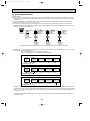
Page 21
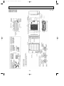
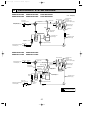
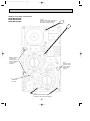
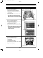
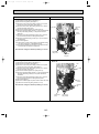
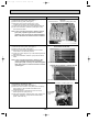
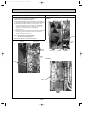
PUHZ-RP60VHA2
PUHZ-RP71VHA2
Unit : mm
21
er
0m
m
Ov
0m
mm
10
10
er
er
Ov
m
Example of Notes
50
mm
FREE
Front piping hole
(Knockout)
Front trunking hole
(Knockout)
92
{92
40
65
45
19
92
75
55
65
45
Power supply wiring hole
(2-{27Knockout)
Right trunking hole
(Knockout)
40
{92
Right piping hole
(Knockout)
63
23 27 92
73
Power supply wiring hole
(2-{27Knockout)
Piping Knockout Hole Details
55
27
Air Intake
Handle for moving
w 1 ···Indication of STOP VALVE connection location.
1···Refrigerant GAS pipe connction (FLARE){15.88(5/8 inch)
2···Refrigerant LIQUID pipe connection (FLARE){ 9.52(3/8 inch)
Ov
10
92
{ 92
40
Power supply wiring hole
(2-{27Knockout)
Rear trunking hole
(Knockout)
Rear piping hole
(Knockout)
Side Air Intake
Handle for moving
Handle for moving
Rear Air Intake
Handle for moving
Side Air Intake
943
er
55
27
330
30
30
23
322
220
175
145
600
145
145
Earth terminal
950
Air Discharge
Installation Feet
175
2-U Shaped notched holes
(Foundfation Bolt M10)
,,
,,
,,
,,
42
Drain hole
(5-{33)
71
2
1
Handle for moving
Service panel
Terminal Connections
Left···Power supply wiring
Reight···Indoor/Outdoor wiring
2-12o36 oval holes
(Foundation Bolt M10)
65
,,,,,,
,,
,,,,
,,
,,,,,,
,,,,
Rear Air Intake
(19)
370
417
28
Ov
73 63
23
73 63
23
473
219
81
45
56
53
71
22
w 1 443
Bottom piping hole
(Knockout)
Rear piping cover
Front piping cover
PUHZ-RP60VHA21
PUHZ-RP71VHA21
673
08.2.22 8:18 AM
w 1 447
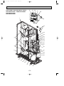
OC374C--1.qxp
Page 22
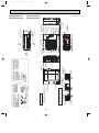
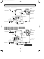
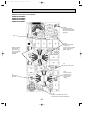
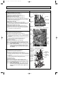
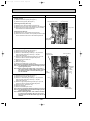
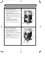
PUHZ-RP60VHA3
PUHZ-RP71VHA3
Unit : mm
r
m
m
0m
1 0m
0
10
er
Ov
15
0
1 0m
er
er
Ov
m
mm
10
Service space
Over
500
Over
Front piping hole
(Knockout)
92
[92
Front trunking hole 40
(Knockout)
65
45
Power supply wiring hole
(2-[27Knockout)
19
92
75
Right piping hole
(Knockout)
Piping Knockout Hole Details
55
[92
Air intake
Handle for moving
w1 • • • Indication of STOP VALVE connection location.
150
Dimensions of space needed
for service access are
shown in the below diagram.
1····Refrigerant GAS pipe connction (FLARE)[15.88 (5/8 inch)
2····Refrigerant LIQUID pipe connection (FLARE)[ 9.52 (3/8 inch)
Example of Notes
e
Ov
Ov
FREE
55
27
Over
500
40
65
45
Right trunking hole
(Knockout)
92
[92
40
FOUNDATION
Rear piping hole
(Knockout)
Rear trunking hole
(Knockout)
Power supply wiring hole
(2-[27Knockout)
Handle for moving
Handle for moving
Side Air Intake
Rear Air Intake
Piping and wiring connections
can be made from 4 directions:
front, right, rear and below.
Please secure the unit firmly
with 4 foundation (M10) bolts.
(Bolts and washers must be
purchased locally.)
<Foundation bolt height>
4 PIPING-WIRING DIRECTIONS
3 FOUNDATION BOLTS
Power supply wiring hole
(2-[27Knockout)
Over
The diagram below shows a
basic example.
Explantion of particular details is
given in the installation manuals etc.
73 63
23
63
73
30
2 SERVICE SPACE
175
322
600
145
Air Discharge
Installation Feet
66
175
2-U Shaped notched holes
(Foundation Bolt M10)
Handle for moving
30
220
145
145
Earth terminal
950
42
Side Air Intake
1350
Rear Air Intake
Drain hole
(5-[33)
71
2
1
Handle for moving
Service panel
Terminal connection
Left • • • Power supply wiring
Right • • Indoor/Outdoor wiring
2-12o36 Oval holes
(Foundation Bolt M10)
71
635
371
417
1 FREE SPACE (Around the unit)
23 27 92
Less than
73 63
23
55
27
330
30
23
219
19
45
56
370
53
28
Front piping cover
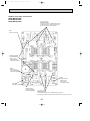
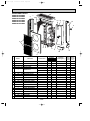
RP·YHA2
RP·VHA2
A
930
1,076
Rear piping cover
Bottom piping hole
(Knockout)
w1 443
23
81
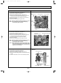
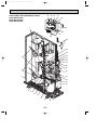
PUHZ-RP100VHA2
PUHZ-RP125VHA2
PUHZ-RP140VHA2
PUHZ-RP100YHA2
PUHZ-RP125YHA2
PUHZ-RP140YHA2
A
08.2.22 8:18 AM
w1 447
OC374C--1.qxp
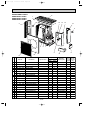
Page 23
Unit : mm
er
1 0m
m
er
15
0
1 0m
er
m
10
Service space
Over
Example of Notes
Ov
Ov
mm
500
Over
Front piping hole
(Knockout)
92
{92
65
Power supply wiring hole
(2-{27Knockout)
Front trunking hole 40
45
(Knockout)
19
92
75
Right piping hole
(Knockout)
Piping Knockout Hole Details
55
{92
Air intake
Handle for moving
w 1 ···Indication of STOP VALVE connection location.
150
Dimensions of space needed
for service access are
shown in the below diagram.
500
40
65
45
Right trunking hole
(Knockout)
92
{92
40
FOUNDATION
Rear piping hole
(Knockout)
Rear trunking hole
(Knockout)
Power supply wiring hole
(2-{27Knockout)
Handle for moving
Handle for moving
Side Air Intake
Rear Air Intake
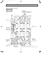
Piping and wiring connections
can be made from 4 directions:
front, right, rear and below.
Please secure the unit firmly
with 4 foundation (M10) bolts.
(Bolts and washers must be
purchased locally.)
<Foundation bolt height>
4 PIPING-WIRING DIRECTIONS
Power supply wiring hole
(2-{27Knockout)
1····Refrigerant GAS pipe connction (FLARE){15.88(5/8 inch)
2····Refrigerant LIQUID pipe connection (FLARE){ 9.52(3/8 inch)
e
Ov
m
0m
00
r1
Ov
FREE
55
27
30
The diagram below shows a
basic example.
Explantion of particular details is
given in the installation manuals etc.
Over
Over
3 FOUNDATION BOLTS
175
322
145
Air Discharge
Installation Feet
600
Rear Air Intake
66
175
2-U Shaped notched holes
(Foundation Bolt M10)
30
220
145
145
Earth terminal
950
42
Handle for moving
Side Air Intake
1350
2 SERVICE SPACE
Drain hole
(5-{33)
71
2
1
Handle for moving
Service panel
Terminal connection
Left···Power supply wiring
Right···Indoor/Outdoor wiring
2-12 x 36 Oval holes
(Foundation Bolt M10)
71
635
371
417
1 FREE SPACE (Around the unit)
73 63
23
63
23 27 92
73
Less than
73 63
23
55
27
330
30
23
219
(19)
45
56
370
53
28
Front piping cover
Rear piping cover
1,079
930
RP·Y
A
RP·V
Bottom piping hole
(Knockout)
w 1 443
24
81
PUHZ-RP100VHA21
PUHZ-RP100VHA3
PUHZ-RP125VHA21
PUHZ-RP140VHA21
PUHZ-RP100YHA21
PUHZ-RP100YHA3
PUHZ-RP125YHA21
PUHZ-RP140YHA21
A
08.2.22 8:18 AM
w 1 447
OC374C--1.qxp
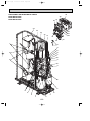
Page 24
Unit : mm
OC374C--1.qxp
08.2.22 8:18 AM
8
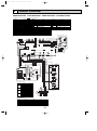
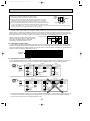
Page 25
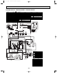
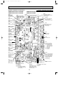
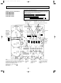
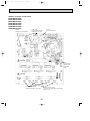
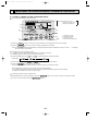
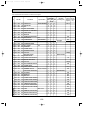
WIRING DIAGRAM
PUHZ-RP35VHA2 PUHZ-RP50VHA2 PUHZ-RP60VHA2 PUHZ-RP71VHA2
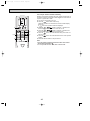
Symbols used in wiring diagram above are,
SYMBOL
TB1
MC
MF1
21S4
63H
SV
TH3, TH33
TH4
TH6
TH7
TH8
LEV(A),LEV(B)
ACL
P.B.
R/S
U/V/W
IPM
CB1~CB3
:Connector,
NAME
Terminal Block<Power Supply, Indoor/Outdoor>
Motor for Compressor
Fan Motors
Solenoid Valve (Four-Way Valve)
High Pressure Switch
Solenoid Valve (Bypass Valve)
Thermistor<Outdoor Pipe>
Thermistor<Discharge>
Thermistor<Outdoor 2-Phase Pipe>
Thermistor<Outdoor>
Thermistor<Heatsink>
Electronic Expansion Valve
Reactor
Power Circuit Board
Connection Terminal<L/N-Phase>
Connection Terminal<U/V/W-Phase>
Power module
Main Smoothing Capacitor
:Terminal(block)
SYMBOL
N.F.
LI/LO
NI/NO
E
52C
C.B.
SW1
SW4
SW5
SW6
SW7
SW8
SW9
SW10
LED1,LED2
F1~4
NAME
Noise Filter Circuit Board
Connection Terminal<L-Phase>
Connection Terminal<N-Phase>
Connection Terminal<Ground>
52C Relay
Controller Circuit Board
Switch<Forced Defrost, Defect History
Record Reset, Refrigerant Address>
Switch<Test Operation>
Switch<Function Switch>
Switch<Model Select>
Switch<Function Setup>
Switch
Switch
Switch<Model Select>
Light Emitting Diodes
<Operation Inspection Indicators>
Fuse<T6.3AL250V>
SYMBOL
SWP
CN31
SS
CNM
CNMNT
NAME
Switch<Pump Down>
Connector<Emergency Operation>
Connector<Connection for Option>
Connector<A-Control Service Inspection Kit>
Connector
<Connected to Optional M-NET Adapter Board>
Connector
CNVMNT
<Connected to Optional M-NET Adapter Board>
Connector
CNDM
< Connected for Option (Contact Input)>
X51,X52,X55 Relay
TH7 TH6
12
TH33
(YLW)
1234
TH7/6
(RED)
TH3
TH4
LEV-A
C.B.
LEV-B
SW11
SW1
LED2
CN52C
(RED)
12
SW7
A
CNS
(WHT) 3 2 1
12
34
F1
CNAC
(WHT)
F4
21S4
1 (GRN)
3
21S4
SV2
1 (BLU)
3
3
SS
1 (WHT)
SV
ACL
LO
NO
N.F.
S
W
CN3
(WHT)
CN2
(WHT)
CB2
CB3
3
1
CB1
CNAC2
(RED)
TH8
21
V
3
12
CN4
(WHT)
U
R
CN5
(RED)
1
I PM
21
PFC
52C
CN52C
(BLK)
7 6 54 3 2 1
RED
w2
U
BLK
WHT
P.B.
1 2
MC
W V
CNAC1
(WHT)
w1 MODEL SELECT
SW6
SW10
ON
OFF
1 2 3 4 5 6
50V
ON
OFF
60V
ON
OFF
71V
ON
OFF
(RED)
CN5
1 2
ON
OFF
1 2 3 4 5 6
1 2
TB1
ON
OFF
1 2 3 4 5 6
L
1 2
1 2 3 4 5 6
N
S1 S2 S3
NO FUSE
BREAKER
ON
OFF
1 2
POWER SUPPLY
~/N
230V 50Hz
w2 RP60/71V only
INDOOR
UNIT
M-NET ADAPTER
SYMBOL
TB7
CN5
CND
CN2M
SW1
SW11
NAME
Terminal Block<M-net connection>
Connector<Transmission>
Connector<Power Supply>
Connector<M-NET communication>
Switch<Status of communication>
Switch<Address setting : 1st digit>
SYMBOL
SW12
LED1
LED2
LED3
LED4
LED5
NAME
Switch<Address setting : 2nd digit>
LED<Power Supply : DC5V>
LED<Connection to Outdoor Unit>
LED<Transmission : Sending>
LED<Transmission : Recelving>
LED<Power Supply : DC12V>
25
NI
ON
OFF
E
35V
LI
MODEL
S
TB7
M-NET
X51
X52
F3
X55
F2
B
1 2
LED1
12
CN2M
(WHT)
LED5
wh 1
CN51
(WHT)
12345
CN4
(WHT)
21
CNDM
(WHT)
1
CN2
(WHT)
1234567
M-NET SUBSTRATE
123
SW1
3
TRANS
CNDC
(PNK)
LED4
SW9
SW6
SW5
CN31
SW10
1 2 3 4 5 6 7 8 9 10 11 12 13 14
CNM
(WHT)
SW4 SWP SW8
63H
(YLW)
F5
LED1
MF1
123456 123 12345
LEV-B
CNVMNT CNMNT
(RED)
(WHT)
(WHT)
SW12
LED3
w1
123456
LEV-A
(WHT)
12 12
TH3 TH4
(WHT) (WHT)
LED2
CNF1
(WHT)
1
4567
3
1
CND
(WHT)
TH33
12345
CN5
(WHT)
When M-NET adaptor is connected
123
OC374C--1.qxp
08.2.22 8:18 AM
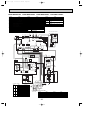
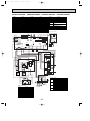
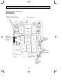
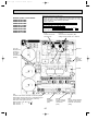
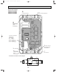
Page 26
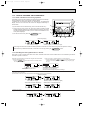
PUHZ-RP35VHA21 PUHZ-RP50VHA21 PUHZ-RP60VHA21 PUHZ-RP71VHA21
NAME
Terminal Block<Power Supply, Indoor/Outdoor>
Motor for Compressor
Fan Motor
Solenoid Valve (Four-Way Valve)
High Pressure Switch
Solenoid Valve (Bypass Valve)
Thermistor<Outdoor Pipe>
Thermistor<Discharge>
Thermistor<Outdoor 2-Phase Pipe>
Thermistor<Outdoor>
Thermistor<Heatsink>
Electronic Expansion Valve
Reactor
Power Circuit Board
Connection Terminal<L/N-Phase>
Connection Terminal<U/V/W-Phase>
Power module
Main Smoothing Capacitor
SYMBOL
N.F.
LI/LO
NI/NO
E
52C
C.B.
SW1
NAME
Noise Filter Circuit Board
Connection Terminal<L-Phase>
Connection Terminal<N-Phase>
Connection Terminal<Ground>
52C Relay
Controller Circuit Board
Switch<Forced Defrost, Defect History
Record Reset, Refrigerant Address>
Switch<Test Operation>
Switch<Function Switch>
Switch<Model Select>
Switch<Function Setup>
Switch
Switch
Light Emitting Diodes
<Operation Inspection Indicators>
Fuse<T6.3AL250V>
Switch<Pump Down>
SW4
SW5
SW6
SW7
SW8
SW9
LED1,LED2
F1~4
SWP
SYMBOL
CN31
SS
CNM
CNMNT
NAME
Connector<Emergency Operation>
Connector<Connection for Option>
Connector<A-Control Service Inspection Kit>
Connector
<Connected to Optional M-NET Adapter Board>
Connector
CNVMNT
<Connected to Optional M-NET Adapter Board>
Connector
CNDM
< Connected for Option (Contact Input)>
X51,X52,X55 Relay
12
2 1
6
1
LEV-A
(WHT)
TH7/6 TH3 TH4
(RED) (WHT) (WHT)
1
6
1
1
3
2
2
F1
21S4 3
(GRN)
F4
3
1
M-NET SUBSTRATE
2
1
CND
(WHT)
3 1
CN31
A B S
TB7
M-NET
4
1
3
X51
1
2
X55
F3
CNAC
(WHT)
1
5
X52
F2
CNS
(WHT)
LED4
3
1 2
1 2
CNDC 1
(PNK)
3
CN52C
(RED)
CN4
(WHT)
7
14
CNM
(WHT)
SW12
LED3
1
1
TRANS
5
5
CN2
(WHT)
1
LEV-B CNVMNT CNMNT
(RED) (WHT) (WHT)
63H
(YLW)
3
3
3
1
SW6
TH33
(YLW)
4
w1
SW1
1
LED2
w2
CNDM
(WHT)
1
1
5
SW11
SW1
LED5 CN2M
(WHT)
LED1
t°
CN51
(WHT)
3
t°
t° t°
SW5
CNF1
7 (WHT)
5
5
3
SW4 SWP SW8
t°
1
M
LED2
MF1
MS
3~
M
TH7 TH6 TH3 TH4
LED1
C. B.
LEV-B
SW9 SW7
63H
TH33
LEV-A
CN5
(WHT)
When M-NET adaptor is connected
1 SV2
3
1 SS
(WHT)
(BLU)
21S4
SV
RED
RED
WHT
WHT
w3 60 / 71 only
RED
WHT
N. F.
ACL
MC
MS
3~
w3 60/71 ony
NO
U
CN52C
(BLK)
2
2
CN5 1
(RED) 2
PFC
2
1
52C
BLK
P. B.
LO
RED
W V
WHT
IPM
2
E3
CN4 1
(WHT) 2
1
THB
CN3 1
(WHT) 2
3
t°
CNAC2
(RED)
TABV
TABW
RED
WHT
TABS
5
1
CN5
(RED)
TABU
TABR
CN2
(WHT)
CB2
CB3
1
7
2
2
E2
CB1
1
CNAC1
(WHT)
3
w4 For 60/71
w4
U
MODEL
35V
SW5-6 w2
SW6
ON
OFF
50V
ON
OFF
YLW
ON
OFF
POWER SUPPLY
~/N 230V 50Hz
ON
OFF
ON
OFF
1 2 3 4 5 6
ON
OFF
ON
OFF
1 2 3 4 5 6 7 8
w2. SW5 -1 to 5 : Function Switch
EI
CY1
CY2
S1
S3 TB1
S2
INDOOR
UNIT
1 2 3 4 5 6
1 2 3 4 5 6 7 8
71V
N
U
1 2 3 4 5 6
1 2 3 4 5 6 7 8
60V
L
ON
OFF
1 2 3 4 5 6 7 8
EI
GRN/YLW
w1MODEL SELECT
U
BLU
NI
ORN
U
LI
BRN
CNAC1
(WHT)
LI
1
NI
3
RED
SYMBOL
TB1
MC
MF1
21S4
63H
SV
TH3, TH33
TH4
TH6
TH7
TH8
LEV-A, LEV-B
ACL
P.B.
R/S
U/V/W
IPM
CB1~CB3
1 2 3 4 5 6
M-NET ADAPTER
SYMBOL
TB7
CN5
CND
CN2M
SW1
SW11
NAME
Terminal Block<M-net connection>
Connector<Transmission>
Connector<Power Supply>
Connector<M-NET communication>
Switch<Status of communication>
Switch<Address setting : 1st digit>
26
SYMBOL
SW12
LED1
LED2
LED3
LED4
LED5
NAME
Switch<Address setting : 2nd digit>
LED<Power Supply : DC5V>
LED<Connection to Outdoor Unit>
LED<Transmission : Sending>
LED<Transmission : Recelving>
LED<Power Supply : DC12V>
OC374C--1.qxp
08.2.22 8:18 AM
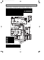
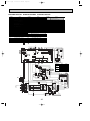
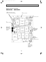
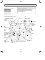
Page 27
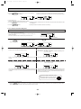
PUHZ-RP35VHA3 PUHZ-RP50VHA3 PUHZ-RP60VHA3 PUHZ-RP71VHA3
SYMBOL
TB1
MC
MF1
21S4
63H
SV
TH3, TH33
TH4
TH6
TH7
TH8
LEV-A, LEV-B
ACL
P.B.
R/S
U/V/W
IPM
CB1~CB3
NAME
Terminal Block<Power Supply, Indoor/Outdoor>
Motor for Compressor
Fan Motor
Solenoid Valve (Four-Way Valve)
High Pressure Switch
Solenoid Valve (Bypass Valve)
Thermistor<Outdoor Pipe>
Thermistor<Discharge>
Thermistor<Outdoor 2-Phase Pipe>
Thermistor<Outdoor>
Thermistor<Heatsink>
Electronic Expansion Valve
Reactor
Power Circuit Board
Connection Terminal<L/N-Phase>
Connection Terminal<U/V/W-Phase>
Inverter
Main Smoothing Capacitor
SYMBOL
N.F.
LI/LO
NI/NO
E
52C
C.B.
SW1
NAME
Noise Filter Circuit Board
Connection Terminal<L-Phase>
Connection Terminal<N-Phase>
Connection Terminal<Ground>
52C Relay
Controller Circuit Board
Switch<Forced Defrost, Defect History
Record Reset, Refrigerant Address>
Switch<Test Operation>
Switch<Function Switch>
Switch<Model Select>
Switch<Function Setup>
Switch
Switch
Light Emitting Diodes
<Operation Inspection Indicators>
Fuse<T6.3AL250V>
Switch<Pump Down>
SW4
SW5
SW6
SW7
SW8
SW9
LED1,LED2
F1~4
SWP
SYMBOL
CN31
SS
CNM
CNMNT
NAME
Connector<Emergency Operation>
Connector<Connection for Option>
Connector<A-Control Service Inspection Kit>
Connector
<Connected to Optional M-NET Adapter Board>
Connector
CNVMNT
<Connected to Optional M-NET Adapter Board>
Connector
CNDM
< Connected for Option (Contact Input)>
X51,X52,X55 Reray
LEV-B
M
M
5
TH7 TH6 TH3 TH4
5
3
5
C. B.
1
6
1
1
3
7
14
CN52C
(RED)
CN4
(WHT)
1 2
1 2
CNDC 1
(PNK)
2
2
F1
21S4 3
(GRN)
F4
3
1
M-NET SUBSTRATE
2
1
CND
(WHT)
3 1
CN31
3
A B S
TB7
M-NET
4
1
3
X51
1
2
X55
F3
CNAC
(WHT)
1
5
X52
F2
CNS
(WHT)
5
CN51
(WHT)
1
TRANS
1
CNM
(WHT)
63H
(YLW)
CN2
(WHT)
3
LEV-B CNVMNT CNMNT
(RED) (WHT) (WHT)
LED5 CN2M
(WHT)
LED1
1
SW9 SW7
6
LEV-A
(WHT)
CNDM
(WHT)
1
2 1
SW5
12
LED4
SW6
4
TH7/6 TH3 TH4
(RED) (WHT) (WHT)
w1
SW1
1
SW12
LED3
SW4 SWP SW8
1
3
3
LED2
t°
LED1
3
TH33
(YLW)
SW11
SW1
3
t°
w1
CNF1
7 (WHT)
1
t°
LED2
MF1
MS
3~
t°
1
t°
1
5
TH33
LEV-A
CN5
(WHT)
When M-NET adaptor is connected
63H
1 SV2
3
1 SS
(WHT)
(BLU)
21S4
RED
SV
w3 60 / 71 only
RED
RED
WHT
t°
WHT
WHT
N. F.
ACL
MC
MS
3~
U
CN52C
(BLK)
2
2
CN5 1
(RED) 2
PFC
2
1
52C
BLK
w3 60/71 ony
NO
RED
P. B.
WHT
W V
LO
IPM
2
E3
CN4 1
(WHT) 2
1
THB
CN3 1
(WHT) 2
TABV
TABW
3
t°
CNAC2
(RED)
RED
WHT
TABS
5
1
CN5
(RED)
TABU
TABR
CN2
(WHT)
CB2
CB3
1
7
2
2
E2
CB1
1
CNAC1
(WHT)
3
W1MODEL SELECT
SW5-6 w2
1 2 3 4 5 6 7 8
1 2 3 4 5 6
U
LI
NI
U
EI
ON
OFF
1 2 3 4 5 6 7 8
L
71V
N
S1
S2
S3 TB1
ON
OFF
ON
OFF
1 2 3 4 5 6 7 8
1 2 3 4 5 6
W2. SW5 -1 to 5 : Function Switch
INDOOR
UNIT
POWER SUPPLY
~/N 230V 50Hz
M-NET ADAPTER
SYMBOL
TB7
CN5
CND
CN2M
SW1
SW11
CY1
CY2
1 2 3 4 5 6
NAME
Terminal Block<M-net connection>
Connector<Transmission>
Connector<Power Supply>
Connector<M-NET communication>
Switch<Status of communication>
Switch<Address setting : 1st digit>
SYMBOL
SW12
LED1
LED2
LED3
LED4
LED5
NAME
Switch<Address setting : 2nd digit>
LED<Power Supply : DC5V>
LED<Connection to Outdoor Unit>
LED<Transmission : Sending>
LED<Transmission : Recelving>
LED<Power Supply : DC12V>
27
U
EI
NI
60V
ON
OFF
CNAC1
(WHT)
ON
OFF
LI
ON
OFF
w4
U
1
BRN
50V
1 2 3 4 5 6
YLW
1 2 3 4 5 6 7 8
w4 For 60/71
3
ORN
ON
OFF
GRN/YLW
SW6
ON
OFF
BLU
35V
RED
MODEL
OC374C--1.qxp
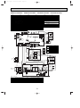
08.2.22 8:18 AM
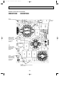
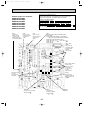
Page 28
PUHZ-RP100VHA2 PUHZ-RP125VHA2 PUHZ-RP140VHA2
:Connector,
NAME
Terminal Block<Power Supply, Indoor/Outdoor >
Motor for Compressor
Fan Motors
Solenoid Valve (Four-Way Valve)
Solenoid Valve (Bypass Valve)
High Pressure Switch
Thermistor<Outdoor Pipe>
Thermistor<Discharge>
Thermistor<Outdoor 2-Phase Pipe>
Thermistor<Outdoor>
Thermistor<Heatsink>
Thermistor<Outdoor Pipe>
Electronic Expansion Valve
Reactor
52C Relay
Rush Current Protect Resistor
Active Filter Module
Main Smoothing Capacitor
:Terminal(block)
SYMBOL
P.B.
TABU/V/W
TABS/T
TABP1/P2/P
TABN1/N2/N
DS2,3
IPM
N.F.
LI/LO
NI/NO
EI
C.B.
F1~4
SW1
NAME
Power Circuit Board
Connection Terminal<U/V/W-Phase>
Connection Terminal<L/N-Phase>
Connection Terminal<DC Voltage>
Connection Terminal<DC Voltage>
Diode Bridge
Power Module
Noise Filter Circuit Board
Connection Lead<L-Phase>
Connection Lead<N-Phase>
Connection Terminal<Ground>
Controller Circuit Board
Fuse<T6.3AL250V>
Switch<Forced Defrost, Defect History Record
Reset, Refrigerant Address>
Switch<Test Operation>
Switch<Function Switch>
Switch<Model Select>
SW4
SW5
SW6
TH33 TH7 TH6 TH3 TH4
LEV-A
LEV-B
123456
123456
C.B.
SYMBOL
SW7
SW8
SW9
SW10
SWP
CN31
LED1,LED2
SS
CNM
CNMNT
CNVMNT
CNDM
NAME
Switch<Function Setup>
Switch
Switch
Switch<Model Select>
Switch<Pump Down>
Connector<Emergency Operation>
Light Emitting Diodes
<Operation Inspection Indicators>
Connector<Connection for Option>
Connector<A-Control Service Inspection Kit>
Connector<Connected to Optional M-NET Adapter Board>
Connector<Connected to Optional M-NET Adapter Board>
Connector< Connected for Option (Contact Input)>
When M-NET adaptor is connected
SW11
SW1
LED2
3
SW7
SW9
SW6
CN31
F1
12
34
F4
3
52C
21S4
1 (GRN) 3
1 (BLK) 3
21S4
CNDM
(WHT)
123
12345
TB7
A B S
M-NET
X51
X52
F3
CNAC
(WHT)
X53
F2
21
123
w1
CN51
(WHT)
CN4
(WHT)
X55
1
CN2
(WHT)
1234567
M-NET SUBSTRATE
LED1
CNM
(WHT)
LED4
12
CN2M
LED5 (WHT)
1 2 3 4 5 6 7 8 9 10 111213 14
TRANS
CNDC
(PNK)
CNS
(WHT) 3 2 1
LEV-B CNVMNT CNMNT
(RED) (WHT) (WHT)
SW10
MF2
F5
LEV-A
(WHT)
TH3 TH4
(WHT) (WHT)
12345
SW12
LED3
w1
123
SW1
TH7/6
(RED)
12
SW4 SWP SW8 SW5
TH33
(YLW)
12
LED1
1234
63H
(YLW)
MF1
12
LED2
1
4 5 6 7 CNF2
(WHT)
(WHT)
1
4 5 6 7 CNF1
3
1
CND
(WHT)
SYMBOL
TB1
MC
MF1,MF2
21S4
SV
63H
TH3
TH4
TH6
TH7
TH8
TH33
LEV-A,B
DCL
52C
RS
ACTM
CB
12345
CN5
(WHT)
Symbols used in wiring diagram above are,
SV2
1 (BLU)
3
SS
1 (WHT)
SV
P.B.
~
N.F.
DS3
TABS
-
~
+
~
LO
NO
1 2
CN5
(RED)
NI
EI
-
DS2
TABP1
(RED)
CNAC2
3 1
TABN1
(WHT)
CNAC1
3 1
LI
TABV
12
+
RED
U
V
TABW
12
TABP
CB
~
+
TABN2
BLK
12
CN3
(WHT)
CN5
(RED)
CN4
(WHT)
TABN
+
TABU
TABP2
IPM
WHT
1234567
+
CN2
(WHT)
-
CNDC 1 3
(PNK)
123456
TH8
TABT
CNAF
(WHT)
W
MC
w1MODEL SELECT
MODEL
SW6
ON
100V OFF
TB1 L
DCL
N
1 2 3 4 5 6
S1 S2 S3
ON
125V OFF
RS
L2
L1
52C
123456
+
P
-
N1
N2
I
ACTM
NO FUSE
BREAKER
SW10
ON
OFF
1 2
ON
OFF
1 2 3 4 5 6
INDOOR
UNIT
POWER SUPPLY
~/N
230V 50Hz
28
ON
140V OFF
1 2
ON
OFF
1 2 3 4 5 6
1 2
M-NET ADAPTER
SYMBOL
TB7
CN5
CND
CN2M
SW1
SW11
SW12
LED1
LED2
LED3
LED4
LED5
NAME
Terminal Block<M-net connection>
Connector<Transmission>
Connector<Power Supply>
Connector<M-NET communication>
Switch<Status of communication>
Switch<Address setting : 1st digit>
Switch<Address setting : 2nd digit>
LED<Power Supply : DC5V>
LED<Connection to Outdoor Unit>
LED<Transmission : Sending>
LED<Transmission : Recelving>
LED<Power Supply : DC12V>
OC374C--1.qxp
08.2.22 8:18 AM
Page 29
PUHZ-RP100VHA21 PUHZ-RP125VHA21 PUHZ-RP140VHA21 PUHZ-RP100VHA3
SYMBOL
TB1
MC
MF1, MF2
21S4
63H
SV
TH3, TH33
TH4
TH6
TH7
TH8
LEV-A, LEV-B
DCL
ACTM
CB
P.B.
TABU/V/W
TABS/T
NAME
Terminal Block<Power Supply, Indoor/Outdoor >
Motor for Compressor
Fan Motor
Solenoid Valve (Four-Way Valve)
High Pressure Switch
Solenoid Valve (Bypass Valve)
Thermistor<Outdoor Pipe>
Thermistor<Discharge>
Thermistor<Outdoor 2-Phase Pipe>
Thermistor<Outdoor>
Thermistor<Heatsink>
Electronic Expansion Valve
Reactor
Active Filter Module
Main Smoothing Capacitor
Power Circuit Board
Connection Terminal<U/V/W-Phase>
Connection Terminal <L/N-Phase>
SYMBOL
TABP1/P2/P
TABN1/N2/N
DS2, DS3
IPM
N.F.
LI / LO
NI / NO
EI, E2
52C
C.B.
SW1
SW4
SW5
SW6
SW7
SW8
SW9
NAME
Connection Terminal<DC Voltage>
Connection Terminal<DC Voltage>
Diode Bridge
Power Module
Noise Filter Circuit Board
Connection Terminal<L-Phase>
Connection Terminal<N-Phase>
Connection Terminal<Ground>
52C Relay
Controller Circuit Board
Switch<Forced Defrost, Defect History Record
Reset, Refrigerant Address>
Switch<Test Operation>
Switch<Function Switch>
Switch<Model Select>
Switch<Function Setup>
Switch
Switch
SYMBOL
SWP
CN31
SS
CNM
CNMNT
NAME
Switch<Pump Down>
Connector<Emergency Operation>
Connector<Connection for Option>
Connector<A-Control Service Inspection Kit>
Connector
<Connected to Optional M-NET Adapter Board>
Connector
CNVMNT
<Connected to Optional M-NET Adapter Board>
Connector
CNDM
< Connected for Option (Contact Input)>
LED1, LED2 Light Emitting Diodes
<Operation Inspection Indicators>
Fuse< T6.3AL250V>
F1~F4
X51,X52,X55 Relay
When M-NET adaptor is connected
M
M
5
C. B.
t°
t°
4
12
2 1
TRANS
1
CN52C
(RED)
CN4
(WHT)
CN2
(WHT)
14
CNM
(WHT)
CNDC 1
(PNK)
2
2
F1
3
21S4 3
(GRN)
F4
3
1
4
1
M-NET SUBSTRATE
CN2M
(WHT)
CND
(WHT)
3 1
3
A B S
TB7
M-NET
3
X51
X55
F3
CNAC
(WHT)
1
X52
F2
1
1
7
CNS
(WHT)
2
CN51
(WHT)
2
SW12
LED4
CN31
1 2
2 1
7
LED3
w1
1
3
5
CNVMNT CNMNT
(WHT) (WHT)
1
63H
(YLW)
1
3
3
LEV-B
(RED)
3
5
1
1
CNDM
(WHT)
LEV-A
(WHT)
6
SW5
1
SW6
6
SW1
1
TH7/6 TH3 TH4
(RED) (WHT) (WHT)
CNF2
(WHT)
2
5
SW4 SWP SW8
1
LED1
3
LED2
1
t°
w2
1
TH33
(YLW)
7
t° t°
1 SV2
3
1 SS
(WHT)
(BLU)
21S4
SV
BLU
WHT
N. F.
NO
2
CN52C
(BLK)
P. B.
1
CNAF
(WHT)
CNDC
(PNK) 2
6
1
2
1
TABN1
3
2
RED
DCL
4
BLK
RED
L1
L2
1
P
N1
N2
BLK
6
RED
L
N
S1
S2
WHT
M-NET ADAPTER
NAME
Terminal Block<M-net connection>
Connector<Transmission>
Connector<Power Supply>
Connector<M-NET communication>
Switch<Status of communication>
Switch<Address setting>
Switch<Address setting : 2nd digit>
LED<Power Supply : DC5V>
LED<Connection to Outdoor Unit>
LED<Transmission : Sending>
LED<Transmission : Recelving>
LED<Power Supply : DC12V>
NI
EI
U
w1MODEL SELECT
CY1
CY2
MODEL
SW5-6 w2
SW6
ON
100VHA2 OFF
S3 TB1
Io
ON
OFF
1 2 3 4 5 6 7 8
125V
ON
OFF
140V
ON
OFF
1 2 3 4 5 6
ON
OFF
1 2 3 4 5 6 7 8
ACTM
SYMBOL
TB7
CN5
CND
CN2M
SW1
SW11
SW12
LED1
LED2
LED3
LED4
LED5
U
LI
MC
BLU
w3
BRN
MC
W
ORN
V
MS
3~
1
GRN/YLW
YLW
U
CN5
(RED)
CNAC1
(WHT)
RED
TABP
w3 RP100VHA21
V
U
W
M
3~
E2
WHT TABN2
RED
CNAC2
(RED)
U
WHT
CB
CN5
(RED)
CN4
(WHT)
TABN
TABW
2
WHT
1
1
2
1
2
WHT TABV
BLK
t° 2
TABS WHT
TABP1 RED
7
1 CN3
2 (WHT)
TH8
DS2
3
IPM
BLK
CN2
(WHT)
TABT BLU
3
1
TABP2
7
DS3
BLU
4
2
1
52C
LO
RED
MF2
MS
3~
1
CNF1
(WHT)
RED TABU
MF1
MS
3~
7
SW11
CN5
(WHT) SW1
1
LED2
5
3
LED1
TH7 TH6 TH3 TH4
LEV-B
LED5
TH33
LEV-A
SW9 SW7
63H
INDOOR
UNIT
POWER SUPPLY
~/N 230V 50Hz
1 2 3 4 5 6 7 8
ON
100VHA3 OFF
1 2 3 4 5 6
ON
OFF
1 2 3 4 5 6 7 8
w2. SW5 -1 to 5 : Function Switch
29
1 2 3 4 5 6
ON
OFF
1 2 3 4 5 6
OC374C--1.qxp
08.2.22 8:18 AM
Page 30
PUHZ-RP100YHA2 PUHZ-RP125YHA2 PUHZ-RP140YHA2
SYMBOL
TB1
TB2
MC
MF1,MF2
21S4
SV
63H
TH3
TH4
TH6
TH7
TH33
LEV
ACL1~ACL4
CB1,CB2
CK
RS
P.B.
TB-U/V/W
TB-L1/L2/L3
TB-P2
TB-C1
TB-N1
CT1, CT2
NAME
Terminal Block(Power Supply )
Terminal Block(Indoor/Outdoor )
Motor for Compressor
Fan Motor
Solenoid Valve (Four-Way Valve)
Solenoid Valve (Bypass Valve)
High Pressure Switch
Thermistor(Outdoor Pipe)
Thermistor(Discharge)
Thermistor(Outdoor 2-Phase Pipe)
Thermistor(Outdoor)
Thermistor(Outdoor Pipe)
Linear Expansion Valve
Reactor
Main Smoothing Capacitor
Capacitor
Rush Current Protect Resistor
Power Circuit Board
Connection Terminal(U/V/W-Phase)
Connection Terminal(L1/L2/L3-Power Supply)
Connection Terminal
Connection Terminal
Connection Terminal
Current Trans
SYMBOL
N.F.
LI1/LI2/LI3/NI
LO1/LO2/LO3/NO
GD1
CONV.B
L1-A1/IN
L1-A2/OU
L2-A2/OU
L3-A2/OU
N-IN
CK-OU
C.B.
F1,F2
F3,F4
SW1
SW4
SW5
SW6
SW7
SW8
SW9
SW10
SWP
NAME
Noise Filter Circuit Board
Connection Terminal(L1/L2/L3/N-Power Supply)
Connection Terminal(L1/L2/L3/N-Power Supply)
Connection Terminal(Ground)
Converter Circuit Board
Connection Terminal(L1-Power Supply)
Connection Terminal(L1-Power Supply)
Connection Terminal(L2-Power Supply)
Connection Terminal(L3-Power Supply)
Connection Terminal
Connection Terminal
Controller Circuit Board
FUSE(T6.3AL250V)
FUSE(T6.3AL250V)
Switch(Forced Defrost, Defect History Record
Reset, Refrigerant Adress)
Switch(Test Operation)
Switch(Function Switch)
Switch(Model Select)
Switch(Function Switch)
Switch(Function Switch)
Switch(Function Switch)
Switch(Model Select)
Switch(Pump Down)
SYMBOL
CN31
21S4
SV2
SS
LEV-A/LEV-B
63H
TH3
TH4
TH7/6
TH33
CNF1/CNF2
LED1/LED2
CNM
CNVMNT
CNMNT
CN3S
CNDM
CN51
NAME
Connector(Emergency Operation)
Connector(Four-Way Valve)
Connector(Bypass Valve)
Connector Connection for Option)
Connector(LEV)
Connector(High Pressure Switch)
Connector(Thermistor)
Connector(Thermistor)
Connector(Thermistor)
Connector(Thermistor)
Connector(Fan Motor Operation)
LED(Operatiion Inspection Indicators)
Connector(A-Control Service Inspection Kit)
Connector(Connect to Optional M-NET Adapter Board)
Connector(Connect to Optional M-NET Adapter Board)
Connector( Connection for Option)
Connector( Connection for Option)
Connector( Connection for Option)
M-NET ADAPTER
Terminal Block(M-NET connection )
Connector(Transmission)
Connector(Power Supply)
Connector(M-NET communication)
Switch(Status of communication)
Switch(Address setting: 1st digit)
Symbols used in wiring diagram above are,
SW12
LED1
LED2
LED3
LED4
LED5
: Connector,
Switch(Address setting. 2nd digit )
LED(Power Supply: DC5V)
LED(Connection to Outdoor Unit)
LED(Transmission: Sending)
LED(Transmission: Receiving)
LED(Power Supply: DC12V)
: Terminal(block)
63H
TH4
SV2
1 (BLU)
3
SV
(w1 MODEL SELECT)
SW6
MODELS
P.B.
CT2
TB-W
+
WHT V
12
12
CN5 CN4
(RED) (WHT)
BLK
TB-L2
WHT
TB-L1
RED
CB1
CNAC1 1
(WHT)
1 2
1 2 3 4 5 6
ON
OFF
1 2
TB-C1
TB-N1
CB2
CK
L1-A1
S3
N.F.
1 2 3 4 5 6
123
CN7
(WHT)
TB-P2
S2
NO FUSE
BREAKER
1 2
ON
OFF
L3-OU
TB-L3
MC
RS
TB2
S1
INDOOR
UNIT
-
140Y
ON
OFF
ON
OFF
U
RED
TB-U
CT1
+
125Y
ON
OFF
SW10
1 2 3 4 5 6
BLK W
TB-V
-
ON
OFF
CNCT 1 2
(RED)
3
1
3 CNAC2
(RED)
L1-A2
1234567
CN2
(WHT)
100Y
CK-OU
123
CN7
(WHT)
CND
(WHT)
M-NET
L2-A2
21S4
3
TB7
A B S
SS
1 (WHT)
L1-OU
3
21S4
1 (GRN)
N-IN
BLK
F4
123
CONV.B.
L1-IN
F1
CNS
(WHT) 3 2 1
w1
L2-OU
F3
CNAC
(WHT)
12
34
X55
F2
SW12
LED3
LED4
LED1
CNDC
(PNK)
CN4
(WHT)
21
LED2
L3-A2
1
CN2
(WHT)
1234567
12345
CN5
(WHT)
SW6
CN31
X51
TRANS
SW9 SW7
w1
SW11
SW1
12
CN2M
LED5 (WHT)
1 2 3 4 5 6 7 8 9 10 11121314
CNM
SW1
123456 123 12345
LEV-B CNVMNT CNMNT
(RED)
(WHT) (WHT)
3
F5
123456
LEV-A
(WHT)
X52
MF2
12 12
TH3 TH4
(WHT) (WHT)
M-NET ADAPTER (OPTION)
SW10
4 5 6 7 CNF2
(WHT)
1234
TH7/6
(RED)
LED1
1
12
TH33
(YLW)
LED2
4 5 6 7 CNF1 1 2 3
(WHT) CN3N
63H
(YLW)
3 1
1
MF1
LEV
LEV
C.B.
CN51 CNDM CN3S
(WHT) (WHT) (WHT)
12345 123 123
TH3
SW4 SWP SW8 SW5
TH33 TH7 TH6
BLU
TB7
CN5
CND
CN2M
SW1
SW11
ACL1
TB1
L1
RED
LI1
LO1
RED
L2
WHT
LI2
LO2
WHT
L3
BLK
LI3
LO3
BLK
NI
NO
ACL2
POWER SUPPLY
3N~
400V
50Hz
ACL3
N
BLU
GD1
GD2
30
CNDC 1
(PNK)
3
3
1 CNL
(BLU)
BLU
ACL4
OC374C--2.qxp
08.2.22 8:16 AM
Page 31
PUHZ-RP100YHA21 PUHZ-RP125YHA21 PUHZ-RP140YHA21 PUHZ-RP100YHA3
SYMBOL
TB1
TB2
MC
MF1, MF2
21S4
63H
SV
TH3, TH33
TH4
TH6
TH7
LEV-A, LEV-B
ACL1~ACL4
CB1, CB2
CK
RS
P.B.
TB-U/V/W
TB-L1/L2/L3
TB-P2
NAME
Terminal Block<Power Supply >
Terminal Block<Indoor/Outdoor >
Motor for Compressor
Fan Motor
Solenoid Valve (Four-Way Valve)
High Pressure Switch
Solenoid Valve (Bypass Valve)
Thermistor<Outdoor Pipe>
Thermistor<Discharge>
Thermistor<Outdoor 2-Phase Pipe>
Thermistor<Outdoor>
Electronic Expansion Valve
Reactor
Main Smoothing Capacitor
Capacitor
Rush Current Protect Resistor
Power Circuit Board
Connection Terminal<U/V/W-Phase>
Connection Terminal<L1/L2/L3-Power Supply>
Connection Terminal
SYMBOL
TB-C1
TB-N1
N.F.
LI1/LI2/LI3/NI
LO1/LO2/LO3/NO
GD1, GD3
CONV.B.
L1-A1/IN
L1-A2/OU
L2-A2/OU
L3-A2/OU
N-IN
CK-OU
C.B.
SW1
NAME
Connection Terminal
Connection Terminal
Noise Filter Circuit Board
Connection Terminal<L1/L2/L3/N-Power Supply>
Connection Terminal<L1/L2/L3/N-Power Supply>
Connection Terminal<Ground>
Converter Circuit Board
Connection Terminal<L1-Power Supply>
Connection Terminal<L1-Power Supply>
Connection Terminal<L2-Power Supply>
Connection Terminal<L3-Power Supply>
Connection Terminal
Connection Terminal
Controller Circuit Board
Switch<Forced Defrost, Defect History Record
Reset, Refrigerant Adress>
Switch<Test Operation>
Switch<Function Switch>
Switch<Model Select>
Switch<Function Setup>
SW4
SW5
SW6
SW7
SYMBOL
SW8
SW9
SWP
CN31
LED1/LED2
F1~F4
CNM
CNMNT
NAME
Switch
Switch
Switch<Pump Down>
Connector<Emergency Operation>
LED<Operatiion Inspection Indicators>
FUSE<T6.3AL250V>
Connector<A-Control Service Inspection Kit>
Connector
<Connect to Optional M-NET Adapter Board>
Connector
<Connect to Optional M-NET Adapter Board>
Connector
< Connection for Option(Contact Input)>
Connector< Connection for Option>
Connector< Connection for Option>
CNVMNT
CNDM
CN3S
CN51
63H
CNF2
(WHT)
1
1
3
63H
(YLW)
TRANS
1
6
1
LEV-A
(WHT)
6
LEV-B
(RED)
1
1 3 1
5
CNVMNT CNMNT
(WHT) (WHT)
14
CNM
(WHT)
1
CNDC
(PNK)
2
F4
1
3
1 21S4 3
(GRN)
1 SV2
(BLU)
5
3
CN5
(WHT)
3
1
CND
(WHT)
3 1
3
A B S
TB7
1
M-NET
1 SS
(WHT)
w1MODEL SELECT
2
BLU
BLK
3 4
X55
F1
CNS
(WHT)
3
X52
F3
CNAC
(WHT)
1 2
SW12
LED3
LED4
M-NET SUBSTRATE
2
1
3
1
X51
7
F2
LED2
CN31
CN4
(WHT)
1 2
CN2
(WHT) 7
SW7
1 2 21
TH3 TH4
(WHT) (WHT)
SW11
SW1
1
SW9
1
4
TH7/6
(RED)
SW5
1 3
TH33
(YLW)
3
w1
SW6
w2
3
2
5
t°
LED5 CN2M
(WHT)
LED1
7
5
SW1
1
MS
3~
When M-NET adaptor is connected)
3
SW4 SWP SW8
MF2
t°
M
LED1
1
MS
3~
t° t°
LEV-B
M
LED2
MF1
t°
CNF1
7 (WHT)
LEV-A
CNDM CN3S
(WHT) (WHT)
C.B.
TH7 TH6 TH3 TH4
CN51
(WHT)
TH33
21S4
SW5-6 w2
SW6
MODEL
SV
ON
100YHA2 OFF
W MC
V
U
V MS
U 3~
1 2 3 4 5 6 7 8
1 2 3 4 5 6 7 8
+
CB2
3
3
1
CK
CONV.B.
2
2
CNCT
(RED) 1
2 1
L1-IN
L1-A1
CB1
BLK
WHT
+
TB-N1
TB-C1
RED
BLK
+
TB-P2
L2
L3
N
RED
LI1
WHT
LI2 U
BLK
BLU
LI3
NI
ACL1
LO1
RED
U
LO2
WHT
U
LO3
BLK
U
NO
BLU
ACL2
ACL3
+
+
U
GD1
GD3
CNDC
(PNK)
2
M-NET ADAPTER
TB7
CN5
CND
CN2M
SW1
SW11
Terminal Block<M-NET connection >
Connector<Transmission>
Connector<Power Supply>
Connector<M-NET communication>
Switch<Status of communication>
Switch<Address setting: 1st digit>
SW12
LED1
LED2
LED3
LED4
LED5
Switch<Address setting. 2nd digit >
LED<Power Supply: DC5V>
LED<Connection to Outdoor Unit>
LED<Transmission: Sending>
LED<Transmission: Receiving>
LED<Power Supply: DC12V>
31
1
3
3
U -1 CNL
(BLU)
BLU
CNAC2
3 (RED)
TB1
L1
POWER SUPPLY
3N~
400V 50Hz
3
RED
CNAC1
(WHT) 1
RED
N.F.
NO FUSE
BREAKER
L1-A2
RS
+
RED
BLK CK-OU
RED
L2-A2
WHT
TB-L1
1 2 3 4 5 6
w2. SW5 -1 to 5 : Function Switch
L1-OU RED
BLK
TB-L2
ON
OFF
N-IN
TB-L3
1 2 3 4 5 6
ON
100YHA3 OFF
L2-OU WHT
YLW
W MC
WHT
RED
TB-U
+
BLK
1 2 3 4 5 6
ON
OFF
WHT
--
RED
S3
2 CN5
1 (RED)
ON
OFF
1 2 3 4 5 6
ON
OFF
1 2 3 4 5 6 7 8
w3
TB-W
+
140Y
RED
ORN
S2
2 CN4
1 (WHT)
2
BRN
INDOOR
UNIT
CN2
(WHT)
TB-V
2
ON
OFF
M
3~
7
--
TB2
S1
1
125Y
L3-A2
1 3
CN7
(WHT)
1 2 3 4 5 6 7 8
w3. For RP100YHA21
7
L3-OU BLK
3
CN7
(WHT)
P.B.
ON
OFF
ACL4
OC374C--2.qxp
9
08.2.22 8:16 AM
Page 32
WIRING SPECIFICATIONS
9-1. FIELD ELECTRICAL WIRING (power wiring specifications)
Outdoor unit model
Outdoor unit power supply
RP35, 50V
~/N (single), 50 Hz,
230 V
*1
Circuit rating
Wiring
Wire No. o
size (mm2)
Outdoor unit input capacity
Main switch (Breaker)
Outdoor unit power supply
Outdoor unit power supply earth
Indoor unit-Outdoor unit
Indoor unit-Outdoor unit earth
Remote controller-Indoor unit
Outdoor unit L-N (single)
Outdoor unit L1-N, L2-N, L3-N (3 phase)
Indoor unit-Outdoor unit S1-S2
Indoor unit-Outdoor unit S2-S3
Remote controller-Indoor unit
RP60, 71V
~/N (single), 50 Hz,
230 V
RP100, 125V
~/N (single), 50 Hz,
230 V
RP140V
~/N (single), 50 Hz,
230 V
RP100, 125, 140Y
3N ~ (3phase), 50 Hz,
400 V
16 A
25 A
32 A
40 A
16 A
*2
*2
*3
2 o Min. 1.5
1 o Min. 1.5
3 o 1.5 (Polar)
1 o Min. 1.5
2 o 0.3 (Non-polar)
2 o Min. 2.5
1 o Min. 2.5
3 o 1.5 (Polar )
1 o Min. 1.5
2 o 0.3 (Non-polar )
2 o Min. 4
1 o Min. 4
3 o 1.5 (Polar)
1 o Min. 1.5
2 o 0.3 (Non-polar)
2 o Min. 6
1 o Min. 6
3 o 1.5 (Polar)
1 o Min. 1.5
2 o 0.3 (Non-polar)
4 o Min. 1.5
1 o Min. 1.5
3 o 1.5 (Polar)
1 o Min. 1.5
2 o 0.3 (Non-polar)
*4
AC 230 V
AC 230 V
AC 230 V
AC 230 V
AC 230 V
*4
*4
*4
AC 230 V
DC 24 V
DC 12 V
AC 230 V
DC 24 V
DC 12 V
AC 230 V
DC 24 V
DC 12 V
AC 230 V
DC 24 V
DC 12 V
AC 230 V
DC 24 V
DC 12 V
*1. A breaker with at least 3 mm contact separation in each poles shall be provided. Use earth leakage beaker(NV).
The breaker shall be provided to ensure disconnection of all active phase conductor of the supply.
*2. Refer to 9-3.
*3. The 10 m wire is attached in the remote controller accessory.
*4. The figures are NOT always against the ground.
S3 terminal has DC 24 V against S2 terminal. However between S3 and S1, these terminals are NOT electrically insulated by the transformer or other device .
Notes: 1. Wiring size must comply with the applicable local and national code..
2. Power supply cables and Indoor/Outdoor unit connecting cables shall not be lighter than polychloroprene sheathed flexible cable.
(Design 60245 IEC 57)
3. Install an earth longer than other cables.
230V
Single phase
Isolator
3 poles isolator
S1
S1
A-Control S2
Outdoor Unit
S2
S3
S3
A-Control
Indoor Unit
Warning:
In case of A-control wiring,
there is high voltage potential on the S3 terminal caused by electrical circuit design that has no electrical insulation between
power line and communication signal line. Therefore, please turn off the main power supply when servicing. And do not touch the S1, S2, S3 terminals
when the power is energized. If isolator should be used between indoor unit and outdoor unit, please use 3-pole type.
1:1 system
Electrical wiring
Synchronized twin and triple system Electrical wiring
• Synchronized twin
Outdoor
unit
Unit
power
supply
B
C
B Earth leakage breaker
C wiring circuit breaker or
isolating switch
L
N
S1
S2
S3
Indoor/outdoor
unit connection
cable
Outdoor
unit
Indoor
unit
1
2
S1
S2
S3
Remote
controller
Unit
power
supply
B
C
B Earth leakage breaker
C wiring circuit breaker or
isolating switch
L
N
S1
S2
S3
Indoor/outdoor
unit connection
cable
Indoor
unit
1
2
Indoor
unit
1
2
Remote
controller
S1
S2
S3
S1
S2
S3
• Synchronized triple
Outdoor
unit
Unit
power
supply
B
C
B Earth leakage breaker
C wiring circuit breaker or
isolating switch
32
Indoor
unit
1
2
L
N
S1
S2
S3
Indoor/outdoor
connection cable
S1
S2
S3
Remote
controller
Indoor
unit
Indoor
unit
1
2
1
2
S1
S2
S3
S1
S2
S3
OC374C--2.qxp
08.2.22 8:16 AM
Page 33
9-2. SEPARATE INDOOR UNIT/ OUTDOOR UNIT POWER SUPPLIES
The following connection patterns are available.
The outdoor unit power supply patterns vary on models.
1:1 System
A Outdoor unit power supply
B Earth leakage breaker
C Wiring circuit breaker or isolating switch
D Outdoor unit
E Indoor unit/outdoor unit connecting cords
F Remote controller
G Indoor unit
H Option
J Indoor unit power supply
<For models without heater>
* The optional indoor power supply terminal kit is required.
G
D
A
B
L
N
C
J
S1
S2
S3
B
L
N
C
H
S1
S2
S3
E
1
2
F
* Affix a label B that is included with the manuals near each wiring diagram for the indoor and outdoor units.
Simultaneous twin/triple system
A Outdoor unit power supply
B Earth leakage breaker
C Wiring circuit breaker or isolating switch
D Outdoor unit
E Indoor unit/outdoor unit connecting cords
F Remote controller
G Indoor unit
H Option
J Indoor unit power supply
<For models without heater>
* The optional indoor power supply terminal kits are required.
A
B
C
D
G
G
G
L
N
L
N
L
N
L
N
S1
S2
S3
S1
S2
S3
1
2
1
2
S1
S2
S3
J
B
C
E
F
H
S1
S2
S3
1
2
* Affix a label B that is included with the manuals near each wiring diagram for the indoor and outdoor units.
If the indoor and outdoor units have separate power supplies, refer to the table below.
If the optional indoor power supply terminal kit is used, change the indoor unit
electrical box wiring referring to the figure in the right and the DIP switch settings of the
Electric heater
outdoor unit control board.
(For models with
heater)
Indoor unit specifications
Required
L
N
Required
S1
S2
S3
ORANGE
CND
Indoor unit
control board
Indoor unit power supplied from outdoor unit
(when shipped from factory)
Electric heater
(For models with
heater)
L
N
Connectors
CND
S1
S2
S3
* There are 3 types of labels (labels A, B, and C). Affix the appropriate labels to
the units according to the wiring method.
If the indoor and
outdoor units have
separate power
supplies, change the
connections of the
connectors as shown
in the following
figure.
BLUE YELLOW
YELLOW BLUE
3
ON
OFF
1 2
(SW8)
Set the SW8-3 to ON.
CND
Required
BLUE YELLOW
BLUE YELLOW
Indoor power supply terminal kit (option)
Indoor unit electrical box connector connection change
Label affixed near each wiring diagram
for the indoor and outdoor units
Outdoor unit DIP switch settings (when
using separate indoor unit/outdoor unit
power supplies only)
Connectors (connections when shipped
from the factory are for indoor unit power
supplied from outdoor unit)
ORANGE
CND
Indoor unit
control board
Separate indoor unit/outdoor unit power
supplies
Indoor unit model
Indoor unit power supply
Indoor unit input capacity
Main switch (Breaker)
Indoor unit power supply
Indoor unit power supply earth
Indoor unit-Outdoor unit
Indoor unit-Outdoor unit earth
Remote controller-Indoor unit
RP35~140
~/N (single), 50 Hz, 230 V
16 A
*1
Circuit
rating
Wiring
Wire No. o size
(mm2)
2 o Min. 1.5
1 o Min. 1.5
*2
2 o Min. 0.3
–
*3
2 o 0.3 (Non-polar)
Indoor unit L-N
*4
AC 230 V
Indoor unit-Outdoor unit S1-S2
*4
–
Indoor unit-Outdoor unit S2-S3
*4
DC24 V
Remote controller-Indoor unit
*4
DC12 V
*1. A breaker with at least 3 mm contact separation in each pole shall be provided. Use earth leakage breaker (NV).
The breaker shall be provided to ensure disconnection of all active phase conductor of the supply.
*2. Max. 120 m
*3.The 10 m wire is attached in the remote controller accessory. Max. 500 m
*4.The figures are NOT always against the ground.
Notes: 1. Wiring size must comply with the applicable local and national code.
2. Power supply cables and indoor unit/outdoor unit connecting cables shall not be lighter than polychloroprene sheathed flexible cable.
(Design 60245 IEC 57)
3. Install an earth longer than other cables.
33
OC374C--2.qxp
08.2.22 8:16 AM
Page 34
9-3. INDOOR – OUTDOOR CONNECTING CABLE
The cable shall not be lighter than design 60245 IEC or 60227 IEC.
Wire No. o Size (E)
Outdoor power supply
Indoor unit-Outdoor unit
Indoor unit-Outdoor unit earth
Max. 45m
Max. 50m
Max. 80m
3 o 1.5 (polar)
3 o 2.5 (polar)
3 o 2.5 (polar) and S3 separated
1 o Min. 1.5
1 o Min. 2.5
1 o Min. 2.5
w The Max. cable length may vary depending on the condition of installation, humidity or materials, etc.
Indoor/Outdoor separate
power supply
Wire No. o Size (E)
Indoor unit-Outdoor unit
2 o Min. 0.3
Max. 120m
Indoor unit-Outdoor unit earth
—
w The optional indoor power supply terminal kit is necessary
Be sure to connect the indoor-outdoor connecting cables directly to the units (no intermediate connections).
Intermediate connections can lead to communication errors if water enters the cables and causes insufficient
insulation to ground or a poor electrical contact at the intermediate connection point.
34
OC374C--2.qxp
08.2.22 8:16 AM
Page 35
9-4. M-NET WIRING METHOD
(Points to notice)
(1) Outside the unit, transmission wires should stay away from electric wires in order to prevent electromagnetic noise from
making an influence on the signal communication. Place them at intervals of more than 5cm. Do not put them in the same
conduit tube.
(2) Terminal block (TB7) for transmission wires should never be connected to 220~240V power supply. If it is connected,
electronic parts on M-NET P.C. board may burn out.
(3) Use 2-core x 1.25mm2 shield wire (CVVS, CPEVS) for the transmission wire. Transmission signals may not be sent or
received normally if different types of transmission wires are put together in the same multi-conductor cable. Never do this
because this may cause a malfunction.
Group
remote
controller
Power
supply
unit for
transmission
wire
Refrigerant
address 00
M-NET
address 01
Refrigerant
address 00
M-NET
address 02
Refrigerant
address 00
M-NET
address 03
A-control
A-control
A-control
remote
remote
remote
controller
controller
controller
It would be ok if M-NET wire (non-polar, 2-cores) is arranged in addition to the wiring for A-control.
(4) Ground only one of any appliances through M-NET transmission wire (shield wire). Communication error may occur due to
the influence of electromagnetic noise.
“Ed” error will appear on the LED display of outdoor unit.
“0403” error will appear on the central-control remote controller.
✕ Bad example (Multi spot grounding of shield wire)
Central
remote
controller
Power
supply
appliance
M-NET type
outdoor unit
M-NET type
outdoor unit
M-NET type
outdoor unit
M-NET transmission wire
Good example 1 (Single spot grounding of shield wire)
Central
remote
controller
Power
supply
appliance
M-NET type
outdoor unit
M-NET type
outdoor unit
M-NET type
outdoor unit
M-NET transmission wire
Good example 2 (Single spot grounding of shield wire)
Central
remote
controller
Power
supply
appliance
M-NET type
outdoor unit
M-NET type
outdoor unit
M-NET type
outdoor unit
M-NET transmission wire
If there are more than 2 grounding spots on the shield wire, noise may enter into the shield wire because the ground wire
and shield wire form 1 circuit and the electric potential difference occurs due to the impedance difference among grounding
spots. In case of single spot grounding, noise does not enter into the shield wire because the ground wire and shield wire
do not form 1 circuit.
To avoid communication errors caused by noise, make sure to observe the single spot grounding method described in the
installation manual.
35
OC374C--2.qxp
08.2.22 8:16 AM
Page 36
● M-NET wiring
(1) Use 2-core x 1.25mm2 shield wire for electric wires.
M-NET
terminal
(Excluding the case connecting to system controller.)
Ground
block
wire
(2) Connect the wire to the M-NET terminal block.Connect one core of the
transmission wire (non-polar) to A terminal and the other to B. Peel the
A B S
shield wire, twist the shield part to a string and connect it to S terminal.
Transmission Shield
(3) In the system which several outdoor units are being connected, the terminal
wire part
(A, B, S) on M-NET terminal block should be individually wired to the other
outdoor unit’s terminal, i.e. A to A, B to B and S to S. In this case, choose one of those outdoor units and drive a screw
to fix an ground wire on the plate as shown on the right figure.
9-4-1. M-NET address setting
In A-control models, M-NET address and refrigerant address should be set only for the outdoor unit. Similar to CITY MULTI
system, there is no need to set the address of outdoor unit and remote controller. To construct a central control system, the
setting of M-NET address should be conducted only upon the outdoor unit. The setting range should be 1 to 50 (the same as
that of the indoor unit in CITY MULTI system), and the address number should be consecutively set in a same group.
23
901
23
901
901
901
78
901
~
45 6
45 6
23
45 6
23
tens
digit
78
78
setting SW12
78
901
50
23
45 6
2
23
45 6
1
45 6
SW11
ones
Switng digit
78
<Setting example> M-NET Address No.
Address number can be set by using rotary switches
(SW11 for ones digit and SW12 for tens digit), which
is located on the M-NET board of outdoor unit.
(Initial setting: all addresses are set to “0”.)
78
9-4-2. Refrigerant address setting
In case of multiple grouping system (multiple refrigerant circuits in one group), indoor units should be connected by remote
controller wiring (TB5) and the refrigerant address needs to be set. Leave the refrigerant addresses to “00” if the group setting is not conducted. Set the refrigerant address by using DIP SW1-3 to -6 on the outdoor controller board. [Initial setting: all
switches are OFF. (All refrigerant addresses are “00”.)]
ON
ON
OFF
Refrigerant
address
ON
OFF
1 2 3 4 5 6
0
ON
1 2 3 4 5 6
ON
9
10
ON
11
7
ON
OFF
1 2 3 4 5 6
12
13
1 2 3 4 5 6
6
ON
OFF
1 2 3 4 5 6
OFF
1 2 3 4 5 6
5
OFF
1 2 3 4 5 6
ON
OFF
1 2 3 4 5 6
4
ON
OFF
1 2 3 4 5 6
ON
OFF
1 2 3 4 5 6
3
OFF
1 2 3 4 5 6
8
ON
OFF
1 2 3 4 5 6
2
ON
OFF
OFF
ON
OFF
1 2 3 4 5 6
1
ON
ON
OFF
1 2 3 4 5 6
OFF
1 2 3 4 5 6
1 2 3 4 5 6
14
15
9-4-3. Regulations in address settings
In case of multiple grouping system, M-NET and refrigerant address settings should be done as explained in the above section. Set the lowest number in the group for the outdoor unit whose refrigerant address is “00” as its M-NET address.
Group A
System
controller
Power
supply
unit for
transmission
wire
Group B
Refrigerant
address 00
M-NET
address 01
Group C
Refrigerant
address 00
M-NET
address 02
Refrigerant
address 01
M-NET
address 03
Refrigerant
address 00
M-NET
address 04
TB5
A-control
remote
controller
A-control
remote
controller
A-control
remote
controller
w Refrigerant addresses can be overlapped if they are in the different group.
Group A
System
controller
Power
supply
unit for
transmission
wire
Refrigerant
address 00
M-NET
address 01
Group B
Refrigerant
address 01
M-NET
address 02
Refrigerant
address 00
M-NET
address 04
Refrigerant
address 01
M-NET
address 03
Refrigerant
address 02
M-NET
address 05
TB5
A-control
remote
controller
A-control
remote
controller
w In group B, M-NET address of the outdoor unit whose refrigerant address is “00” is not set to the minimum in the group. As
“3” is right for this situation, the setting is wrong. Taking group A as a good sample, set the minimum M-NET address in
the group for the outdoor unit whose refrigerant address is “00”.
36
OC374C--2.qxp
08.2.22 8:16 AM
10
Page 37
REFRIGERANT SYSTEM DIAGRAM
PUHZ-RP35VHA2
PUHZ-RP50VHA2
PUHZ-RP35VHA21
PUHZ-RP50VHA21
PUHZ-RP35VHA3
PUHZ-RP50VHA3
unit : mm(inch)
Heat exchanger
Stop valve
(with service port)
Refrigerant GAS pipe
connection(1/2)
Charge plug
4-way valve
Strainer
#50
Thermistor TH7
(Outdoor)
Thermistor TH6
(Outdoor 2-phase pipe)
Thermistor TH3
(Outdoor pipe)
Muffler
Distributor
High pressure
switch 63H
Thermistor TH4
(Discharge)
Strainer
#100
Thermistor TH33
(Outdoor pipe)
Muffler
Linear
expansion valve B
Compressor
Power
receiver
Linear expansion valve A
Stop valve
Refrigerant LIQUID pipe
connection(1/4)
Strainer
#100
PUHZ-RP60VHA2
PUHZ-RP71VHA2
PUHZ-RP60VHA21
PUHZ-RP71VHA21
Heat exchanger
Ball valve
Refrigerant GAS pipe
connection(5/8)
Strainer
#50
4-way valve
Thermistor TH7
(Outdoor)
Thermistor TH6
(Outdoor 2-phase pipe)
Oil separator
Bypass valve
Charge plug
(Low pressure)
Charge plug
(High pressure)
Capillary tube
O.D.4.0OI.D.2.4OL500
Capillary tube
O.D.2.5OI.D.0.6OL1000
Thermistor TH3
(Outdoor pipe)
Distributor
High pressure
switch 63H
Strainer
#100
Thermistor TH4
(Discharge)
Strainer
#100
Stop valve
(with service port)
Refrigerant LIQUID pipe
connection(3/8)
Strainer
#100
Power
receiver
Linear
expansion
valve B
Thermistor TH33
(Outdoor pipe)
Muffler Compressor
Linear expansion valve A
Strainer
#100
Refrigerant flow in cooling
Refrigerant flow in heating
37
OC374C--2.qxp
08.2.22 8:16 AM
Page 38
PUHZ-RP60VHA3 PUHZ-RP71VHA3
unit : mm(inch)
Heat exchanger
Refrigerant GAS pipe
connection [15.88(5/8)
Stop valve Strainer
#50
4-way valve
Thermistor TH7
(Outdoor)
Thermistor TH6
(Outdoor 2-phase pipe)
Thermistor TH3
(Outdoor pipe)
Charge plug
(High pressure)
Muffler
Charge plug
(Low pressure)
Distributor
High pressure
switch 63H
Muffler
Thermistor TH4
(Discharge)
Strainer
#100
Linear
expansion valve B
Stop valve
(with service port)
Refrigerant LIQUID pipe
connection [9.52(3/8)
Strainer
#100
Power
receiver
Linear expansion valve A
Strainer
#100
Strainer
#100
Replace filter
Refrigerant GAS pipe
connection(5/8)
Compressor
Restrictor
valve
Strainer
#100
PUHZ-RP100VHA2
PUHZ-RP100VHA21
PUHZ-RP100YHA2
PUHZ-RP100YHA21
PUHZ-RP100VHA3
Thermistor TH33
(Outdoor pipe)
PUHZ-RP125VHA2
PUHZ-RP125VHA21
PUHZ-RP125YHA2
PUHZ-RP125YHA21
PUHZ-RP100YHA3
Ball valve Strainer
#50
Bypass valve
PUHZ-RP140VHA2
PUHZ-RP140VHA21
PUHZ-RP140YHA2
PUHZ-RP140YHA21
Heat exchanger
Thermistor TH7
(Outdoor)
Thermistor TH6
(Outdoor 2-phase pipe)
4-way valve
Thermistor TH3
(Outdoor pipe)
Charge plug
(High pressure)
Muffler
Charge plug
(Low pressure)
Distributor
High pressure
switch 63H
Strainer
#100
Thermistor TH4
(Discharge)
Strainer
#100
Thermistor TH33
(Outdoor pipe)
Linear
expansion valve B
Stop valve
(with service port)
Refrigerant LIQUID pipe
connection(3/8)
Strainer
#100
Power
receiver
Strainer
#100
Compressor
Linear expansion valve A
Restrictor
valve
Strainer
#100
Strainer
#100
Refrigerant flow in cooling
Replace filter
Bypass valve
38
Refrigerant flow in heating
OC374C--2.qxp
08.2.22 8:16 AM
Page 39
10-1. Refrigerant recovering (pump down)
Perform the following procedures to recover the refrigerant when moving the indoor unit or the outdoor unit.
1Turn on the power supply (circuit breaker).
wWhen power is supplied, make sure that “CENTRALLY CONTROLLED” is not displayed on the remote controller. If “CENTRALLY CONTROLLED” is displayed, the refrigerant recovering (pump down) cannot be completed normally.
2After the liquid stop valve is closed, set the SWP switch on the control board of the outdoor unit to ON. The compressor(outdoor unit) and fans (indoor and outdoor units) start operating and refrigerant recovering operation begins. LED1 and LED2
on the control board of the outdoor unit are lit.
wSet the SWP switch (push-button type) to ON in order to perform refrigerant recovering operation only when the unit is
stopped. However, refrigerant recovering operation cannot be performed until compressor stops even if the unit is stopped.
Wait 3 minutes until compressor stops and set the SWP switch to ON again.
3Because the unit automatically stops in about 2 to 3 minutes after the refrigerant recovering operation (LED1 is not lit and
LED2 is lit), be sure to quickly close the gas stop valve.
wIn case the outdoor unit is stopped when LED1 is lit and LED2 is not lit, open the liquid stop valve completely, and then
repeat step 2 3 minutes later.
wIf the refrigerant recovering operation has been completed normally (LED1 is not lit and LED2 is lit), the unit will remain
stopped until the power supply is turned off.
4Turn off the power supply (circuit breaker.)
10-2. Unit replacement operation
When reusing the existing pipes that carried R22 refrigerant for the RP60/71VHA3 and RP100/125/140 models,
replacement operation must be performed before performing a test run.
1If new pipes are used, these procedures are not necessary.
2If existing pipes that carried R22 refrigerant are used for the RP35-71VHA2 and RP35/50VHA3 model, these procedures are
not necessary.
(The replacement operation cannot be performed.)
3During replacement operation, “C5” is displayed on “A-Control Service Tool(PAC-SK52ST)”. (This is applied to only
RP60/71VHA3 and RP100/125/140 models.)
Replacement operation procedures
1Turn on the power supply.
2Set DIP switch SW8-2 on the control board of the outdoor unit to ON to start replacement operation.
• The replacement operation is performed using the cooling system. Cool air will flow from the indoor unit during the replaceTEST RUN
ment operation.
• During the replacement operation,
is displayed on the remote controller and LED1 (green) and LED2 (red) on the
control board of the outdoor unit flash together.
3Replacement operation requires at least two hours to complete.
• After setting switch SW8-2 to ON, the unit automatically stops after 2 hours.
• Replacement operation can be performed repeatedly by setting switch SW8-2 from OFF to ON. Make sure to perform the
operation more than 2 hours. (If the operation is performed less than 2 hours, the existing pipes cannot be cleaned
enough and the unit may be damaged.)
• If replacement operation is performed over 2 hours, this action is recorded into nonvolatile memory of control board.
4Set switch SW8-2 to OFF. (Replacement operation is completed.)
wThe unit can be operated normally by remote controller even if SW8-2 remains ON.
10-3. Start and finish of test run
• Operation from the indoor unit
Execute the test run using the installation manual for the indoor unit.
• Operation from the outdoor unit
By using the DIP switch SW4 on the control board of outdoor unit, test run can be started and finished, and its operation
mode (cooling/heating) can be set up.
<SW4>
1Set the operation mode (cooling/heating) using SW4-2.
2Turn on SW4-1 to start test run with the operation mode set by SW4-2.
C D
3Turn off SW4-1 to finish the test run.
ON
OFF
• There may be a faint knocking sound around the machine room after power is supplied, but this is
1
2
no problem with product because the linear expansion pipe is just moving to adjust opening pulse.
A
B
• There may be a knocking sound around the machine room for several seconds after compressor
C Operation
starts operating, but this is no problem with product because the check valve itself, generates the A Stop
B Cooling D Heating
sound because pressure difference is small in the refrigerant circuit.
Note:
The operation mode cannot be changed by SW4-2 during test run. (To change test run mode, stop the unit by SW4-1,
change the operation mode and restart the test run by SW4-1.)
39
OC374C--2.qxp
11
08.2.22 8:16 AM
Page 40
TROUBLESHOOTING
11-1. TROUBLESHOOTING
<Error code display by self-diagnosis and actions to be taken for service (summary)>
Present and past error codes are logged and displayed on the wired remote controller and control board of outdoor unit.
Actions to be taken for service, which depends on whether or not the trouble is reoccurring at service, are summarized in the
table below. Check the contents below before investigating details.
Unit conditions at service
Error code
Actions to be taken for service (summary)
Displayed
Judge what is wrong and take a corrective action according
to “11-4. Self-diagnosis action table”.
The trouble is reoccurring.
Not displayed
Logged
Conduct trouble shooting and ascertain the cause of the
trouble according to “11-5. Troubleshooting
by inferior phenomena”.
1Consider the temporary defects such as the work of
protection devices in the refrigerant circuit including
compressor, poor connection of wiring, noise and etc.
Re-check the symptom, and check the installation
environment, refrigerant amount, weather when the
trouble occurred, matters related to wiring
and etc.
2Reset error code logs and restart the unit after finishing
service.
3There is no abnormality in electrical component,
controller board, remote controller and etc.
The trouble is not reoccurring.
Not logged
1Re-check the abnormal symptom.
2Conduct trouble shooting and ascertain the cause of the
trouble according to “11-5. Troubleshooting
by inferior phenomena”.
3Continue to operate unit for the time being if the cause
is not ascertained.
4There is no abnormality concerning of parts such as
electrical component, controller board, remote controller
and etc.
11-2. CHECK POINT UNDER TEST RUN
(1) Before test run
• After installation of indoor and outdoor units, piping work and electric wiring work, re-check that there is no refrigerant leakage, loosened connections and incorrect polarity.
• Measure impedance between the ground and the power supply terminal block(L, N) on the outdoor unit by 500V Megger and
check that it is 1.0M" or over.
wDon’t use 500V Megger to indoor/outdoor connecting wire terminal block(S1, S2, S3) and remote controller terminal block
(1, 2). This may cause malfunction.
• Make sure that test run switch (SW4) is set to OFF before turning on power supply.
• Turn on power supply 12 hours before test run in order to protect compressor.
• For specific models which requires higher ceiling settings or auto-recovery feature from power failure, make proper changes
of settings referring to the description of “12. FUNCTION SETTING”.
Make sure to read operation manual before test run. (Especially items to secure safety.)
40
OC374C--2.qxp
08.2.22 8:16 AM
Page 41
"TEST RUN" and the currently selected
operation mode are displayed altemately.
Displays the remaining
test run time.
Operating procedures
1. Turn on the main power supply.
While the room temperature display on the remote
controller is “PLEASE WAIT”, the remote controller is disabled.
Wait until “PLEASE WAIT” disappears before using remote controller.
“PLEASE WAIT” appears for about 2 minutes after power
supply is turned on. w1
2. Press A TEST button twice.
The TEST RUN appears on the screen.
3. Press B OPERATION SWITCH
button.
Cooling mode: Check if cool air blows and water is drained.
Heating mode: Check if warm air blows. (It takes a little
while until warm air blows.)
4. Press C AIR DIRECTION button. Check for correct motion of auto-vanes.
5. Check the outdoor unit fan for
correct running.
B
C
A
[TEST] button
The outdoor unit features automatic capacity control to
provide optimum fan speeds. Therefore, the fan keeps
running at a low speed to meet the current outside air
condition unless it exceeds its available maximum power.
Then, in actuality, the fan may stop or run in the reverse
direction depending on the outside air, but this does not
mean malfunction.
6. Press the ON/OFF button to reset the test run in progress.
Pipe (liquid) temperature
7. Register the contact number.
• In case of test run, the OFF timer will be activated, and the test run will automatically stop after 2 hours.
• The room temperature display section shows the pipe temperature of indoor units during the test run.
• Check that all the indoor units are running properly in case of simultaneous twin and triple operation. Malfunctions may not
be displayed regardless of incorrect wiring.
w1 After turning on the power supply, the system will go into startup mode, “PLEASE WAIT” will blink on the display section of
the room temperature, and lamp(green) of the remote controller will blink.
As to INDOOR BOARD LED, LED1 will be lit up, LED2 will either be lit up in case the address is 0 or turned off in case the
address is not 0. LED3 will blink.
As to OUTDOOR BOARD LED, LED1(green) and LED2(red) will be lit up. (After the startup mode of the system finishes,
LED2(red) will be turned off.)
In case OUTDOOR BOARD LED is digital display,
— and —
will be displayed alternately every second.
• If one of the above operations doesn’t function correctly, the causes written below should be considered. Find causes from
the symptoms.
The below symptoms are under test run mode. “startup” in the table means the display status of w1 written above.
Symptoms in test run mode
OUTDOOR BOARD LED Display
Remote Controller Display
< > indicates digital display.
After “startup” is displayed, only
Remote controller displays “PLEASE
green lights up. <00>
WAIT”, and cannot be operated.
After “startup” is displayed,
green(once) and red(once) blink
After power is turned on, “PLEASE WAIT” alternately. <F1>
is displayed for 3 minutes, then error code
After “startup” is displayed,
is displayed.
green(once) and red(twice) blink
alternately. <F3, F5, F9>
After “startup” is displayed,
green(twice) and red(once) blink
No display appears even when remote
alternately. <EA. Eb>
controller operation switch is turned on.
After “startup” is displayed, only
(Operation lamp does not light up.)
green lights up. <00>
Display appears but soon disappears
even when remote controller is operated.
After “startup” is displayed, only
green lights up. <00>
Cause
• After power is turned on, “PLEASE WAIT” is displayed for 2
minutes during system startup. (Normal)
• Incorrect connection of outdoor terminal block (L1, L2, L3 and
S1, S2, S3.)
• Outdoor unit’s protection devise connector is open.
• Incorrect wiring between the indoor and outdoor unit (Polarity
is wrong for S1, S2, S3.)
• Remote controller transmission wire short.
• There is no outdoor unit of address 0.
(Address is other than 0.)
• Remote controller transmission wire open.
• After canceling function selection, operation is not possible for
about 30 seconds. (Normal)
w Press the remote controller’s CHECK button twice to perform self-diagnosis. See the table below for the contents of LCD display.
LCD
P1
P2
P4
P5
P6
P8
P9
Fb
Contents of trouble
Abnormality of room temperature thermistor
Abnormality of pipe temperature thermistor/Liquid
Abnormality of drain sensor/ Float switch connector open
Drain overflow protection is working.
Freezing/overheating protection is working.
Abnormality of pipe temperature
Abnormality of pipe temperature thermistor/Cond./Eva
Abnormality of indoor controller board
LCD
U1~UP
F3~F9
E0~E5
E6~EF
---FFFF
PA
Contents of trouble
Malfunction outdoor unit
Malfunction outdoor unit
Remote controller transmitting error
Indoor/outdoor unit communication error
No error history
No applied unit
Forced compressor stop(due to water leakage abnormality)
See the table below for details of the LED display (LED 1, 2, 3) on the indoor controller board.
LED1 (microcomputer power supply)
LED2 (remote controller)
Lits when power is supplied.
Lits when power is supplied for wired remote controller.
The indoor unit should be connected to the outdoor unit with address “0” setting.
LED3 (indoor/outdoor communication)
Flash when indoor and outdoor unit are communicating.
41
OC374C--2.qxp
08.2.22 8:16 AM
Page 42
Test run [for wireless remote controller]
TEST RUN
TEMP
ON/OFF
7
FAN
AUTO STOP
VANE
AUTO START
5
MODE
6
3,4
CHECK LOUVER
min
TEST RUN
2
SET
h
RESET
Measure an impedance between the power supply terminal block on
the outdoor unit and ground with a 500V Megger and check that it is
equal to or greater than 1.0M".
1 Turn on the main power to the unit.
TEST RUN
2 Press the
button twice continuously.
(Start this operation from the status of remote controller display
turned off.)
TEST RUN
A
and current operation mode are displayed.
MODE
3 Press the
(
) button to activate COOL mode, then
check whether cool air is blown out from the unit.
MODE
4 Press the
(
) button to activate HEAT mode, then
check whether warm air is blown out from the unit.
FAN
5 Press the
button and check whether strong air is blown out
from the unit.
VANE
6 Press the
button and check whether the auto vane operates
properly.
7 Press the ON/OFF button to stop the test run.
CLOCK
Note:
• Point the remote controller towards the indoor unit receiver
while following steps 2 to 7.
• It is not possible to run in FAN, DRY or AUTO mode.
42
OC374C--2.qxp
08.2.22 8:16 AM
Page 43
11-3. HOW TO PROCEED "SELF-DIAGNOSIS"
11-3-1. When a Problem Occurs During Operation
If a problem occurs in the air conditioner, the indoor and outdoor units will stop,
and the problem is shown in the remote controller display.
[CHECK] and the refrigerant address are displayed on the temperature
display, and the error code and unit number are displayed alternately as
shown below.
I
F
1 (If the outdoor unit is malfunctioning, the unit number will be "00".)
2 In the case of group control, for which one remote controller controls
multiple refrigerant systems, the refrigerant address and error code of the E
unit that first experienced trouble (i.e., the unit that transmitted the error
code) will be displayed.
G
3 To clear the error code, press the
ON/OFF button.
A
B
H
C
D
(Alternating Display)
Error code (2 or 4 digits)
Address (3 digits) or unit number (2 digits)
When using remote-/local-controller combined operation, cancel the error code after turning off remote operation. During
central control by a MELANS controller, cancel the error code by pressing the
ON/OFF button.
11-3-2. Self-Diagnosis During Maintenance or Service
Since each unit has a function that stores error codes, the latest check code can be recalled even if it is cancelled by the remote
controller or power is turned off.
Check the error code history for each unit using the remote controller.
1 Switch to self-diagnosis mode.
2 Set the unit number or refrigerant address you want to diagnose.
F Press the [TEMP] buttons (
H Press the CHECK
button twice within 3 seconds. The display content
will change as shown below.
and
) to select the desired number
or address. The number (address) changes between [01] and [50] or [00]
and [15].
The refrigerant address will begin to blink
approximately 3 seconds after being
Unit number or refrigerant address
to be diagnosed
selected and the self-diagnosis process will begin.
3 Display self-diagnosis results.
<When there is error code history>
(For the definition of each error code, refer to the indoor unit's installation manual or service handbook.)
(Alternating Display)
Error code (2 or 4 digits)
Address (3 digits) or unit number (2 digits)
<When there is no error code history>
4 Reset the error history.
Display the error history in the diagnosis result display screen (see step 3 ).
43
<When there is no corresponding unit>
OC374C--2.qxp
08.2.22 8:16 AM
Page 44
D Press the
ON/OFF button twice within 3 seconds. The self-diagnosis
address or refrigerant address will blink.
When the error history is reset, the display will look like the one shown below.
However, if you fail to reset the error history, the error content will be displayed again.
5 Cancel self-diagnosis.
Self-diagnosis can be cancelled by the following 2 methods.
H Press the
CHECK
5 Press the
button twice within 3 seconds.
ON/OFF button.
➔ Self-diagnosis will be cancelled and the screen will return to the previous state in effect before the start
of self-diagnosis.
➔ Self-diagnosis will be cancelled and the indoor unit will stop.
11-3-3. Remote Controller Diagnosis
If the air conditioner cannot be operated from the remote controller, diagnose the remote controller as explained below.
1 First, check that the power-on indicator is lit.
If the correct voltage (DC12 V) is not supplied to the remote controller, the
indicator will not light.
If this occurs, check the remote controller's wiring and the indoor unit.
Power on indicator
2 Switch to the remote controller self-diagnosis mode.
H Press the CHECK button for 5 seconds or more. The display content will
A Press the FILTER button to start self-diagnosis.
change as shown below.
3 Remote controller self-diagnosis result
[When the remote controller is functioning correctly]
[When the remote controller malfunctions]
(Error display 1) "NG" blinks. ➝ The remote controller's transmitting-receiving circuit is defective.
Check for other possible causes, as there is no problem with the remote
controller.
The remote controller must be replaced with a new one.
[Where the remote controller is not defective, but cannot be operated.]
(Error display 2) [E3], [6833] or [6832] blinks. ➝ Transmission is not possible.
There might be noise or interference on the transmission path, or the indoor unit
or other remote controllers are defective. Check the transmission path and other
controllers.
(Error display 3) "ERC" and the number of data errors are displayed.
➝ Data error has occurred.
The number of data errors is the difference between the number of bits sent from
the remote controller and the number actually transmitted through the transmission path. If such a problem is occurring, the transmitted data is affected by noise,
etc. Check the transmission path.
When the number of data errors is "02":
Transmission data from remote controller
Transmission data on transmission path
4 To cancel remote controller diagnosis
H Press the
CHECK button for 5 seconds or more. Remote controller diagnosis will be cancelled, "PLEASE WAIT" and operation lamp will blink. After
approximately 30 seconds, the state in effect before the diagnosis will be restored.
44
OC374C--2.qxp
08.2.22 8:16 AM
Page 45
11-3-4. Malfunction-diagnosis method by wireless remote controller
<In case of trouble during operation>
When a malfunction occurs to air conditioner, both indoor unit and outdoor unit will stop and operation lamp blinks to inform
unusual stop.
<Malfunction-diagnosis method at maintenance service>
[Procedure]
1. Press the CHECK button twice.
• "CHECK" lights, and refrigerant
address "00" flashes.
• Check that the remote controller's
display has stopped before continuing.
2. Press the temperature
buttons.
• Select the refrigerant address of the
indoor unit for the self-diagnosis.
Note: Set refrigerant address using the
outdoor unit’s DIP switch (SW1).
(For more information, see the
outdoor unit installation manual.)
Refrigerant
address
display
CHECK
CHECK
display
Temperature
button
TEMP
ON/OFF
ON/OFF
button
MODE
FAN
AUTO STOP
VANE
AUTO START
CHECK LOUVER
CHECK
button
min
TEST RUN
SET
h
RESET
CLOCK
HOUR
button
3. Point the remote controller at the • If an air conditioner error occurs, the
sensor on the indoor unit and
indoor unit's sensor emits an intermitpress the HOUR button.
tent buzzer sound, the operation light
flashes, and the error code is
output.
(It takes 3 seconds at most for error
code to appear.)
4. Point the remote controller at the • The check mode is cancelled.
sensor on the indoor unit and
press the ON/OFF button.
45
OC374C--2.qxp
08.2.22 8:16 AM
Page 46
• Refer to the following tables for details on the check codes.
[Output pattern A]
Beeper sounds
OPERATION
INDICATOR
lamp flash
pattern
Beep
Beep Beep Beep
Off
Beep
1st
2 nd
3 rd
nth
On
On
On
On
Beep Beep
1st
Off
On
2 nd · · · Repeated
On
0.5 sec. Approx. 2.5 sec. 0.5 sec. 0.5 sec.
Self-check Approx. 2.5 sec. 0.5 sec. 0.5 sec. 0.5 sec.
starts
(Start signal
Number of blinks/beeps in pattern indicates the check
Number of blinks/beeps in pattern indicates
received)
code in the following table (i.e., n=5 for “P5”)
the check code in the following table
[Output pattern B]
Beeper sounds
OPERATION
INDICATOR
lamp flash
pattern
Beep
Beep Beep Beep
1st
Off
Self-check Approx. 2.5 sec.
starts
(Start signal
received)
On
Approx. 3 sec.
2nd
Beep
Beep
nth
1st
3 rd
On
On
On
0.5 sec. 0.5 sec. 0.5 sec.
On
Off
0.5 sec. Approx. 2.5 sec.
Number of blinks/beeps in pattern indicates the check
code in the following table (i.e., n=5 for “U2”)
On
Approx. 3 sec.
Beep
2 nd · · · Repeated
On
On
0.5 sec. 0.5 sec.
Number of blinks/beeps in pattern indicates
the check code in the following table
[Output pattern A] Errors detected by indoor unit
Wireless remote controller Wired remote controller
Beeper sounds/OPERATION
INDICATOR lamp flashes
Check code
(Number of times)
1
P1
P2
2
P9
3
E6,E7
4
P4
P5
5
PA
6
P6
7
EE
8
P8
9
E4, E5
–
10
–
11
12
Fb
E0, E3
–
–
E1, E2
Symptom
Intake sensor error
Pipe (TH2) sensor error
Pipe (TH5) sensor error
Indoor/outdoor unit communication error
Drain sensor error/Float switch connector open
Drain pump error
Forced compressor stop(due to water leakage abnormality)
Freezing/Overheating safeguard operation
Communication error between indoor and outdoor units
Pipe temperature error
Remote controller signal receiving error
Remark
As for indoor
unit, refer to
indoor unit's
service manual.
–
–
Indoor unit control system error (memory error, etc.)
Remote controller transmission error
Remote controller control board error
[Output pattern B] Errors detected by unit other than indoor unit (outdoor unit, etc.)
Wireless remote controller Wired remote controller
Beeper sounds/OPERATION
Symptom
INDICATOR lamp flashes
Check code
(Number of times)
Indoor/outdoor unit communication error
1
E9
(Transmitting error) (Outdoor unit)
Compressor overcurrent interruption
2
UP
Open/short of outdoor unit thermistors
3
U3,U4
Compressor overcurrent interruption (When compressor locked)
4
UF
5
Abnormal high discharging temperature/insufficient refrigerant
U2
Abnormal high pressure (63H worked)/Overheating
U1,Ud
6
protection operation
Abnormal temperature of heatsink
U5
7
Outdoor unit fan protection stop
8
U8
9
Compressor overcurrent interruption/Abnormal of power module
U6
Abnormality of superheat due to low discharge temperature
10
U7
Abnormality such as overvoltage or voltage shortage and
U9,UH
11
abnormal synchronous signal to main circuit/Current sensor error
–
–
12
–
–
13
Others
Other errors (Refer to the technical manual for the outdoor unit.)
14
Remark
For details, check
the LED display
of the outdoor
controller board.
*1 If the beeper does not sound again after the initial 2 beeps to confirm the self-check start signal was received and
the OPERATION INDICATOR lamp does not come on, there are no error records.
*2 If the beeper sounds 3 times continuously “beep, beep, beep (0.4 + 0.4 + 0.4 sec.)” after the initial 2 beeps to confirm
the self-check start signal was received, the specified refrigerant address is incorrect.
46
OC374C--2.qxp
08.2.22 8:16 AM
Page 47
11-4. SELF-DIAGNOSIS ACTION TABLE
<Abnormalities detected when the power is put on>
Error Code
None
(Note 1) Refer to indoor unit section for code P and code E.
Abnormal points and detection method
—
Case
Judgment and action
1 No voltage is supplied to termi- 1 Check following items.
nal block(TB1) of outdoor unit.
a) Power supply breaker
a) Power supply breaker is
turned off.
b) Connection of power supply terminal
b) Contact failure or disconblock.(TB1)
nection of power supply terminal
c) Connection of power supply terminal
c) Open phase (L or N phase)
block.(TB1)
2 Check following items.
2 Electric power is not charged
to power supply terminal of
outdoor power circuit board.
a) Connection of power supply terminal
a) Contact failure of power
block.(TB1)
supply terminal
b) Connection of terminal on outdoor power
b) Open phase on the outdoor
circuit board.
power circuit board
RP35-71V :
RP35-71V :Disconnection of
Disconnection of connector R or S.
connector R or S
Refer to 11-9.
RP100V~140V:
RP100V-140V :
Disconnection of connector
Disconnection of connector TABT or TABS.
TABT or TABS
Refer to 11-9.
3 Electric power is not supplied
3 Check connection of the connector (CNDC)
to outdoor controller circuit
on the outdoor controller circuit board.
board.
Check connection of the connector, LD1 and
a) Disconnection of connector
LD2 for RP35-71V and CNDC for RP100(CNDC)
140, on the outdoor power circuit board (V) /
noise filter(Y).Refer to 11-9.
.
4 Disconnection of reactor (DCL 4 Check connection of reactor. (DCL or ACL)
RP35-71V: Check connection of “LO” and
or ACL)
“NO” on the outdoor noise filter circuit board.
Check connection of “R” and “S” on the
outdoor power circuit board.
RP100-140V: Check connection of “L1” and
“L2” on the active filter module.(ACTM)
Refer to 11-9.
5 Disconnection of outdoor noise 5 a) Check connection of outdoor noise filter
circuit board.
filter circuit board or parts failb)
Replace outdoor noise filter circuit board.
ure in outdoor noise filter circuit
Refer to 11-9.
board
As for 100-140VHA21 and
100VHA3 type, it is especially
needed to check the resistance
RS1 on the noise filter circuit
board.
6 Defective outdoor power circuit 6 Replace outdoor power circuit board.
board
7 Defective outdoor controller
circuit board
F5
(5201)
63H connector open
1 Disconnection or contact failure
Abnormal if 63H connector circuit is open
of 63H connector on outdoor
for 3 minutes continuously after power supcontroller circuit board
ply.
2 Disconnection or contact failure
63H: High-pressure switch
of 63H
3 63H is working due to defective
parts.
4 Defective outdoor controller
circuit board
47
7 Replace controller board (When items above
are checked but the units can not be
repaired.)
1 Check connection of 63H connector on
outdoor controller circuit board.
Refer to 11-9.
2 Check the 63H side of connecting wire.
3 Check continuity by tester.
Replace the parts if the parts are defective.
4 Replace outdoor controller circuit board.
OC374C--2.qxp
Error Code
EA
(6844)
Eb
(6845)
EC
(6846)
08.2.22 8:16 AM
Page 48
Abnormal points and detection method
Case
Judgment and action
Miswiring of indoor/outdoor unit connecting wire
1. Outdoor controller circuit board can
automatically check the number of
connected indoor units. Abnormal if the
number cannot be checked automatically
due to miswiring of indoor/outdoor unit
connecting wire and etc. after power is
turned on for 4 minutes.
2. Abnormal if outdoor controller circuit
board recognizes excessive number of
indoor units.
1 Contact failure or miswiring of
indoor/outdoor unit connecting
wire
2 Diameter or length of
indoor/outdoor unit connecting
wire is out of specified capacity.
3 Excessive number of indoor
units are connected to 1 outdoor unit.(4 units or more)
4 Defective transmitting receiving
circuit of outdoor controller
circuit board
5 Defective transmitting receiving
circuit of indoor controller
board
6 Defective indoor power board
7 2 or more outdoor units have
refrigerant address “0” .
(In case of group control)
8 Noise has entered into power
supply or indoor / outdoor unit
connecting wire.
1 Check disconnection or looseness or polarity
of indoor/outdoor unit connecting wire of
indoor and outdoor units.
2 Check diameter and length of indoor/outdoor
unit connecting wire.
Total wiring length: 80m
(including wiring connecting each indoor unit
and between indoor and outdoor unit)
Also check if the connection order of flat
cable is S1, S2, S3.
3 Check the number of indoor units that are
connected to one outdoor unit. (If EA is
detected)
4~6 Turn the power off once, and on again to
check.
Replace outdoor controller circuit board,
indoor controller board or indoor power
board if abnormality occurs again.
7 Check if refrigerant addresses (SW1-3 to
SW1-6 on outdoor controller circuit board)
are overlapping in case of group control
system.
Miswiring of indoor/outdoor unit
connecting wire (converse wiring or
disconnection)
Outdoor controller circuit board can
automatically set the unit number of indoor
units.
Abnormal if the indoor unit number can
not be set within 4 minutes after power on
because of Miswiring (converse wiring or
disconnection) of indoor/outdoor unit connecting wire.
1 Contact failure or miswiring of
indoor/outdoor unit connecting
wire
8 Check transmission path, and remove the
2 Diameter or length of
cause.
indoor/outdoor unit connecting
wire is out of specified capacity.
w The descriptions above, 1-8, are for EA, Eb
4 Defective transmitting receiving
and EC.
circuit of outdoor controller circuit
board
5 Defective transmitting receiving
circuit of indoor controller board
6 Defective indoor power board
7 2 or more outdoor units have
refrigerant address “0” .
(In case of group control)
8 Noise has entered into power
supply or indoor/outdoor unit
connecting wire.
Start-up time over
The unit cannot finish start-up process
within 4 minutes after power on.
1 Contact failure of indoor/
outdoor unit connecting wire
2 Diameter or length of indoor/
outdoor unit connecting wire is
out of specified capacity.
7 2 or more outdoor units have
refrigerant address “0” .
(In case of group control)
8 Noise has entered into power
supply or indoor/outdoor unit
connecting wire.
48
OC374C--2.qxp
08.2.22 8:16 AM
Page 49
<Abnormalities detected while unit is operating>
Error Code
Abnormal points and detection method
High pressure (High-pressure switch
63H worked)
Abnormal if high-pressure switch 63H
worked ( w ) during compressor operation.
w 4.15 MPa
63H: High-pressure switch
U1
(1302)
High discharging temperature
(1) Abnormal if discharge temperature
thermistor (TH4) exceeds 125: or
110: continuously for 5 minutes.
Abnormal if condenser/evaporator
temperature thermistor (TH5) exceeds
40: during defrosting and discharge
temperature thermistor (TH4) exceeds
110:.
U2
(1102)
Case
1 Short cycle of indoor unit
2 Clogged filter of indoor unit
3 Decreased airflow caused by
dirt of indoor fan
4 Dirt of indoor heat exchanger
5 Locked indoor fan motor
6 Malfunction of indoor fan motor
7 Defective operation of stop
valve (Not full open)
8 Clogged or broken pipe
9 Locked outdoor fan motor
0 Malfunction of outdoor fan
motor
1 Short cycle of outdoor unit
2 Dirt of outdoor heat exchanger
3 Decreased airflow caused by
defective inspection of outside
temperature thermistor
(It detects lower temperature
than actual temperature.)
4 Disconnection or contact failure
of connector (63H) on outdoor
controller board
5 Disconnection or contact failure
of 63H connection
6 Defective outdoor controller
board
7 Defective action of linear
expansion valve
8 Malfunction of fan driving
circuit
1 Overheated compressor operation caused by shortage of
refrigerant
2 Defective operation of stop
valve
3 Defective thermistor
4 Defective outdoor controller
board
5 Defective action of linear
expansion valve
(2) Abnormal if discharge superheat
(Cooling: TH4 – TH5 / Heating: TH4 –
TH6) increases.
All the conditions in A or B are detected
simultaneously for 10 minutes
continuously after 6 minutes past from
compressor start-up (including the
thermostat indication or recovery from
defrosting).
<Condition A>
• Heating mode
• When discharge superheat is less
than 70 deg.
• When the TH6 temp is more than the
value obtained by TH7 – 5 deg.
• When the condensing temp of TH5 is
less than 35:.
<Condition B>
• During comp operation (Cooling and
Heating)
• When discharge superheat is less
than 80 deg in Cooling.
• When discharge superheat is less
than 90 deg in Heating.
• When condensing temp of TH6 is
more than –40:. (In Cooling only.)
49
Judgment and action
1~6Check indoor unit and repair defect.
7 Check if stop valve is fully open.
8 Check piping and repair defect.
9~2 Check outdoor unit and repair defect.
3 Check the detected temperature of outside
temperature thermistor on LED display.
(SW2 on A-Control Service Tool : Refer to
11-10.)
4~6Turn the power off and check F5 is
displayed when the power is turned again.
When F5 is displayed, refer to “Judgment
and action” for F5.
7 Check linear expansion valve.
Refer to 11-6.
8 Replace outdoor controller board.
1 Check intake superheat.
Check leakage of refrigerant.
Charge additional refrigerant.
2 Check if stop valve is fully open.
34 Turn the power off and check if U3 is displayed when the power is on again.
When U3 is displayed, refer to “Judgement
and action” for U3.
5 Check linear expansion valve.
Refer to 11-6.
OC374C--2.qxp
Error Code
U3
(5104)
08.2.22 8:16 AM
Page 50
Abnormal points and detection method
Open/short circuit of discharge
temperature thermistor (TH4)
Abnormal if open (3: or less) or short
(217: or more) is detected during
compressor operation.
(Detection is inoperative for 10 minutes of
compressor starting process and for 10
minutes after and during defrosting.)
Open/short of outdoor unit thermistors
(TH3, TH6, TH7, and TH8)
Abnormal if open or short is detected
during compressor operation.
Open detection of thermistors TH3 and
TH6 is inoperative for 10 seconds to 10
minutes after compressor starting and 10
minutes after and during defrosting.
WCheck which unit has abnormality in its
thermistor by switching the mode of
U4
SW2. (PAC-SK52ST)
(TH3:5105)
(Refer to 11-10.)
(TH6:5107)
(TH7:5106)
(TH8:5110)
Symbol
TH3
TH6
TH7
TH8
TH8
U5
(4230)
U6
(4250)
U7
(1520)
Judgment and action
Case
1 Check connection of connector (TH4) on the
outdoor controller circuit board.
Check breaking of the lead wire for
thermistor (TH4). Refer to 11-9.
2 Check resistance value of thermistor (TH4) or
temperature by microcomputer.
(Thermistor/TH4: Refer to 11-6.)
(SW2 on A-Control Service Tool: Refer to 11-10.)
3 Replace outdoor controller board.
1 Disconnection or contact
failure of connector (TH4) on
the outdoor controller circuit
board
2 Defective thermistor
3 Defective outdoor controller
circuit board
1 Disconnection or contact failure 1 Check connection of connector (TH3,TH6/TH7)
of connectors
on the outdoor controller circuit board.
Outdoor controller circuit
Check connection of connector (CN3) on the
board: TH3,TH6/TH7
outdoor power circuit board.
Outdoor power circuit board:
Check breaking of the lead wire for thermistor
CN3
(TH3,TH6,TH7,TH8). Refer to 11-9.
2 Defective thermistor
2 Check resistance value of thermistor
3 Defective outdoor controller
(TH3,TH6,TH7,TH8) or check temperature by
circuit board
microcomputer.
(Thermistor/TH3,TH6,TH7,TH8: Refer to 11-6.)
(SW2 on A-Control Service Tool: Refer to 11-10.)
3 Replace outdoor controller circuit board.
WEmergency operation is available in case of
abnormalities of TH3, TH6 and TH7.
Refer to 11-8.
)
(
Thermistors
Name
Thermistor <Outdoor pipe>
Thermistor <Outdoor 2-phase pipe>
Thermistor <Outdoor>
Thermistor <Heatsink> RP35-140V
Internal thermistor RP100-140Y
Temperature of heatsink
Abnormal if heatsink thermistor(TH8)
detects temperature indicated below.
RP35/ 50··········································· 84:
RP60/ 71VHA2 ································· 77:
RP60/ 71VHA21 ································ 84:
RP60/ 71VHA3 ································· 84:
RP100VHA2(1)/VHA3 ························ 77:
RP125/140VHA2(1)···························· 84:
RP100-140YHA2(1)/YHA3 ················· 95:
1 The outdoor fan motor is
locked.
2 Failure of outdoor fan motor
3 Air flow path is clogged.
4 Rise of ambient temperature
5 Defective thermistor
6 Defective input circuit of
outdoor power circuit board
7 Failure of outdoor fan drive
circuit
Open detection
Short detection
– 40: or below
– 40: or below
– 40: or below
– 27: or below
– 35: or below
90: or above
90: or above
90: or above
102: or above
170: or above
12 Check outdoor fan.
3 Check air flow path for cooling.
4 Check if there is something which causes
temperature rise around outdoor unit.
(Upper limit of ambient temperature is 46:.)
Turn off power, and on again to check if U5
is displayed within 30 minutes.
If U4 is displayed instead of U5, follow the
action to be taken for U4.
5 Check resistance value of thermistor (TH8)
or temperature by microcomputer.
(Thermistor/TH8: Refer to 11-6.)
(SW2 on A-Control Service Tool: Refer to 11-10.)
6 Replace outdoor power circuit board.
7 Replace outdoor controller circuit board.
Power module
1 Outdoor stop valve is closed.
Check abnormality by driving power module 2 Decrease of power supply voltage
in case overcurrent is detected.
3 Looseness, disconnection or
(UF or UP error condition)
converse of compressor wiring
connection
4 Defective compressor
5 Defective outdoor power circuit
board
1 Open stop valve.
2 Check facility of power supply.
3 Correct the wiring (U•V•W phase) to
compressor. Refer to 11-9 (Outdoor power
circuit board).
4 Check compressor referring to 11-6.
5 Replace outdoor power circuit board.
Too low superheat due to low discharge
temperature
Abnormal if discharge superheat is
continuously detected less than or equal
to -15: for 3 minutes even though linear
expansion valve has minimum open pulse
after compressor starts operating for 10
minutes.
12 Check the installation conditions of
discharge temperature thermistor (TH4).
1 Disconnection or loose
connection of discharge
temperature thermistor (TH4)
2 Defective holder of discharge
temperature thermistor
3 Disconnection or loose connection
of linear expansion valve’s coil
4 Disconnection or loose
connection of linear expansion
valve’s connector
5 Defective linear expansion valve
50
3 Check the coil of linear expansion valve.
Refer to 11-7.
4 Check the connection or contact of LEV-A and
LEV-B on outdoor controller circuit board.
5 Check linear expansion valve.
Refer to 11-6.
OC374C--2.qxp
08.2.22 8:16 AM
Error Code
U8
(4400)
Page 51
Abnormal points and detection method
Outdoor fan motor
1 Failure in the operation of
Abnormal if rotational frequency of the fan
the DC fan motor
motor is not detected during DC fan motor 2 Failure in the outdoor circuit
operation.
controller board
Fan motor rotational frequency is abnormal if;
• 100 rpm or below detected continuously
for 15 seconds at 20: or more outside
air temperature.
• 50 rpm or below or 1500 rpm or more
detected continuously for 1 minute.
Overvoltage or voltage shortage and
synchronous signal to main circuit
U9
(4220)
Ud
(1504)
UF
(4100)
Case
Abnormal if any of followings are detected
during compressor operation;
• Decrease of DC bus voltage to 310V
(RP35-140V only)
• Instantaneous decrease of DC bus voltage
RP35-140V : 200V,
RP100-140Y : 350V
• Increase of DC bus voltage to
RP35-71V : 420V
RP100-140V : 400V
RP100-140Y : 760V
• Decrease of input current of outdoor unit
to 0.5A only if operation frequency is
more than or equal to 40Hz or compressor current is more than or equal to 5A.
Over heat protection
Abnormal if outdoor pipe thermistor (TH3)
detects 70: or more during compressor
operation.
Compressor overcurrent interruption
(When compressor locked)
Abnormal if overcurrent of DC bus or
compressor is detected within 30 seconds
after compressor starts operating.
Judgment and action
1 Check or replace the DC fan motor.
2 Check the voltage of the outdoor circuit
controller board during operation.
3 Replace the outdoor circuit controller
board. (when the failure is still indicated
even after performing the action 1
above.)
1 Decrease of power supply volt- 1 Check the facility of power supply.
age
2 Disconnection of compressor
2 Correct the wiring (U•V•W phase) to comwiring
pressor. Refer to 11-9 (Outdoor power circuit
board).
3 Defective 52C
3 Replace 52C.
(RP100-140VHA2)
4 Defective noise filter circuit
4 Replace noise filter circuit board.
board
(RP100-140VHA21, RP100VHA3)
(RP100-140VHA21,100VHA3)
5 Disconnection or loose connec- 5 Check CN52C wiring.
tion of CN52C (RP35-71V,
RP100-140VHA21,
RP100VHA3)
6 Defective PFC module of out6 Replace outdoor power circuit board.
door power board (RP35-71V)
(RP35-71V)
7 Defective ACT module
7 Replace ACT module. (RP100-140V)
(RP100-140V)
8 Defective ACT module drive
8 Replace outdoor power circuit board.
circuit of outdoor power circuit
(RP100-140V)
board (RP100-140V)
9 Disconnection or loose connec- 9Check CNAF wiring. (RP100-140V)
tion of CNAF (RP100-140V)
0 Defective outdoor converter cir- 0 Replace outdoor converter circuit board.
cuit board (RP100-140Y)
(RP100-140Y)
1 Defective 52C drive circuit of
1 Replace outdoor controller circuit board.
outdoor controller circuit board
(RP35-140VHA2)
(RP35-140VHA2)
2 Disconnection or loose
2 Check CN5 wiring on the outdoor power circonnection of CN5 on the
cuit board.
outdoor power circuit board
Refer to 11-9.
3 Defective 52C drive circuit of
3 Replace outdoor power circuit board.
outdoor power circuit board
(RP100-140Y)
(RP100-140Y)
4 Disconnection or loose
4 Check CN2 wiring on the outdoor power circonnection of CN2 on the
cuit board. Refer to 11-9.
outdoor power circuit board
1 Defective outdoor fan (fan
motor) or short cycle of outdoor unit during coling operation
2 Defective outdoor pipe thermistor (TH3)
3 Defective outdoor controller
board
1 Check outdoor unit air passage.
1 Stop valve is closed.
2 Decrease of power supply
voltage
3 Looseness, disconnection or
converse of compressor wiring
connection
4 Defective compressor
1 Open stop valve.
2 Check facility of power supply.
5 Defective outdoor power board
51
23 Turn the power off and on again to check
the error code. If U4 is displayed, follow the
U4 processing direction.
3 Correct the wiring (U•V•W phase) to
compressor.
Refer to 11-9 (Outdoor power circuit board).
4 Check compressor.
Refer to 11-6.
5 Replace outdoor power circuit board.
OC374C--2.qxp
Error Code
UH
(5300)
UL
(1300)
08.2.22 8:16 AM
Page 52
Abnormal points and detection method
Case
Judgment and action
Current sensor error
1 Disconnection of compressor
1 Correct the wiring (U•V•W phase) to compresAbnormal if current sensor detects –1.5A to
sor. Refer to 11-9 (Outdoor power circuit
wiring
1.5A during compressor operation. (This
board).
2 Defective circuit of current senerror is ignored in case of test run mode.)
sor on outdoor power circuit
2 Replace outdoor power circuit board.
board
Low pressure
Abnormal if the following conditions are
detected for continuously 3 minutes after
compressor starts heating operating for 10
minutes.
1. Heating mode
Detection mode1
TH7-TH3[4: and
TH5-Indoor room temperature[2:
Detection mode2
TH7-TH3[2:and
TH5-Indoor room temperature[4: and
TH2-Indoor room temperature[4:
2.Cooling mode
TH6-TH7[2: and
TH3-TH7[2: and
Indoor room temperature - Indoor liquid
pipe temperature (TH2)[5:
1 Stop valve of outdoor unit is
1 Check stop valve.
closed during operation.
2 Leakage or shortage of refriger- 2 Check intake superheat.
ant
Check leakage of refrigerant.
Check additional refrigerant.
3 Malfunction of linear expansion 3 Check linear expansion valve.
valve
Refer to 11-6.
4Clogging with foreign objects in 4 After recovering refrigerant, remove water
refrigerant circuit
from entire refrigerant circuit under vacuum
wClogging occurs in the parts
more than 1 hour.
which become below freezing
point when water enters in
refrigerant circuit.
Thermistor TH3:Outdoor liquid pipe temperature
TH5:Indoor cond./eva. temperature
TH7:Outdoor temperature
UP
(4210)
E0
or
E4
Compressor overcurrent interruption
1 Stop valve of outdoor unit is
Abnormal if overcurrent DC bus or comclosed.
pressor is detected after compressor starts 2 Decrease of power supply voltoperating for 30 seconds.
age
3 Looseness, disconnection or
converse of compressor wiring
connection
4 Defective fan of indoor/outdoor
units
5 Short cycle of indoor/outdoor
units
6 Defective input circuit of outdoor controller board
7 Defective compressor
1Open stop valve.
Remote controller transmission
1 Contact failure at transmission
error(E0)/signal receiving error(E4)
wire of remote controller
1 Abnormal if main or sub remote con2 All remote controllers are set
troller cannot receive normally any transas “sub” remote controller. In
mission from indoor unit of refrigerant
this case, E0 is displayed on
address “0” for 3 minutes.
remote controller, and E4 is
(Error code : E0)
displayed at LED (LED1,
LED2) on the outdoor con2 Abnormal if sub remote controller could
not receive any signal for 2 minutes.
troller circuit board.
(Error code: E0)
3 Miswiring of remote controller
4 Defective transmitting receiving
1 Abnormal if indoor controller board can
circuit of remote controller
not receive normally any data from
5 Defective transmitting receiving
remote controller board or from other
circuit of indoor controller
indoor controller board for 3 minutes.
board of refrigerant address “0”
(Error code: E4)
6 Noise has entered into the
2 Indoor controller board cannot receive
transmission wire of remote
any signal from remote controller for 2
controller.
minutes. (Error code: E4)
1 Check disconnection or looseness of indoor
unit or transmission wire of remote controller.
2 Set one of the remote controllers “main” if
there is no problem with the action above.
3 Check wiring of remote controller.
• Total wiring length: max. 500m
(Do not use cable o 3 or more.)
• The number of connecting indoor units:
max. 16units
• The number of connecting remote controller: max. 2units
2 Check facility of power supply.
3 Correct the wiring (U•V•W phase) to compressor. Refer to 11-9 (Outdoor power circuit
board).
4 Check indoor/outdoor fan.
5Solve short cycle.
6Replace outdoor controller circuit board.
7Check compressor. Refer to 11-6.
W Before the replacement of the outdoor controller circuit board, disconnect the wiring to compressor from
the outdoor power circuit board and check the output voltage among phases, U, V, W, during test run.
No defect on board if voltage among phases (U-V,
V-W and W-U) is same. Make sure to perform the
voltage check with same performing frequency.
When it is not the above-mentioned problem of
1~3
4 Diagnose remote controllers.
a) When “RC OK” is displayed, remote controllers have no problem. Turn the power
off, and on again to check. If abnormality
generates again, replace indoor controller
board.
b) When “RC NG” is displayed, replace
remote controller.
c)When “RC E3” or “ERC 00-66” is displayed, noise may be causing abnormality.
∗ If the unit is not normal after replacing indoor
controller board in group control, indoor controller board of address “0” may be abnormal.
52
OC374C--2.qxp
08.2.22 8:16 AM
Error Code
E1
or
E2
E3
or
E5
Page 53
Abnormal points and detection method
Remote controller control board
1 Abnormal if data cannot be normally
read from the nonvolatile memory of the
remote controller control board.
(Error code: E1)
2 Abnormal if the clock function of remote
controller cannot be normally operated.
(Error code: E2)
Case
1 Defective remote controller
Remote controller transmission
error(E3)/signal receiving error(E5)
1 Abnormal if remote controller could not
find blank of transmission path for 6 seconds and could not transmit.
(Error code: E3)
2 Remote controller receives transmitted
data at the same time, compares the
data, and when detecting it, judges
different data to be abnormal 30
continuous times. (Error code: E3)
1 2 remote controller are set as
“main.”
(In case of 2 remote controllers)
2 Remote controller is connected
with 2 indoor units or more.
3 Repetition of refrigerant
address
4 Defective transmitting receiving
circuit of remote controller
5 Defective transmitting receiving
1 Abnormal if indoor controller board could
circuit of indoor controller
not find blank of transmission path.
board
(Error code: E5)
6 Noise has entered into trans2 Indoor controller board receives transmission wire of remote conmitted data at the same time, compares
troller.
the data,and when detecting it, judges
different data to be abnormal 30
continuous times. (Error code: E5)
Judgment and action
1 Replace remote controller.
1 Set a remote controller to main, and the
other to sub.
2 Remote controller is connected with only one
indoor unit.
3 The address changes to a separate setting.
4~6 Diagnose remote controller.
a) When “RC OK” is displayed, remote controllers have no problem.
Turn the power off, and on again to check.
When becoming abnormal again, replace
indoor controller board.
b)When “RC NG” is displayed, replace
remote controller.
c)When “RC E3” or “ERC 00-66” is displayed, noise may be causing abnormality.
E8
(6840)
Indoor/outdoor unit communication
1 Check disconnection or looseness of indoor/
1 Contact failure of indoor/outerror (Signal receiving error)
outdoor unit connecting wire of indoor or outdoor unit connecting wire
(Outdoor unit)
door units.
2 Defective communication circuit
Abnormal if outdoor controller circuit board
of outdoor controller circuit board 2~4 Turn the power off, and on again to
could not receive anything normally for 3
check. Replace indoor controller board or
3 Defective communication cirminutes.
outdoor controller circuit board if abnormalcuit of indoor controller board
ity is displayed again.
4 Noise has entered into indoor/
outdoor unit connecting wire.
E9
(6841)
Indoor/outdoor unit communication
error (Transmitting error) (Outdoor unit)
1 Abnormal if “0” receiving is detected 30
times continuously though outdoor controller circuit board has transmitted “1”.
2 Abnormal if outdoor controller circuit
board could not find blank of transmission
path for 3 minutes.
1 Indoor/ outdoor unit connecting 1 Check disconnection or looseness of
wire has contact failure.
indoor/outdoor unit connecting wire.
2 Defective communication circuit 2~4 Turn the power off, and on again to
of outdoor controller circuit board
check. Replace outdoor controller circuit
3 Noise has entered power supply.
board if abnormality is displayed again.
4 Noise has entered indoor/ outdoor unit connecting wire.
Non defined error code
This code is displayed when non defined
error code is received.
1 Noise has entered transmission wire of remote controller.
2 Noise has entered indoor/ outdoor unit connecting wire.
3 Outdoor unit is not a series of
power-inverter.
4 Model name of remote controller is PAR-S25A.
Serial communication error
1Abnormal if serial communication
between outdoor controller circuit
board and outdoor power circuit board
is defective.
1 Breaking of wire or contact
12 Check connection of each connector CN2
failure of connector CN2
and CN4 between the outdoor controller
between the outdoor controller
circuit board and the outdoor power circuit
circuit board and the outdoor
board.
power circuit board
2 Breaking of wire or contact
failure of connector CN4
between the outdoor controller
circuit board and the outdoor
power circuit board
3 Defective communication circuit 3 Replace outdoor power circuit board.
of outdoor power circuit board
4 Defective communication circuit 4 Replace outdoor controller circuit board.
of outdoor controller circuit board
for outdoor power circuit board
2 Abnormal if communication between
outdoor controller circuit board and
M-NET board is not available.
1 Breaking of wire or contact
1 Check disconnection, looseness, or breaking of
failure of connector between
connection wire between outdoor controller ciroutdoor controller circuit board
cuit board (CNMNT) and M-NET board (CN5).
and M-NET board
2 Check disconnection, looseness, or breaking of
2 Contact failure of M-NET board
connection wire between outdoor controller cirpower supply line
cuit board(CNMNT) and M-NET board (CND).
3 Noise has entered into M-NET 3 Check M-NET transmission wiring method.
transmission wire.
EF
(6607
or
6608)
Ed
(0403)
53
12 Turn the power off, and on again to check.
Replace indoor controller board or outdoor
controller circuit board if abnormality is
displayed again.
3 Replace outdoor unit with power-inverter type
outdoor unit.
4 Replace remote controller with MA remote
controller.
OC374C--2.qxp
Error Code
P8
08.2.22 8:16 AM
Page 54
Abnormal points and detection method
Pipe temperature
1 Slight temperature difference
<Cooling mode>
between indoor room
Detected as abnormal when the pipe temtemperature and pipe <liquid
perature is not in the cooling range 3 minor condenser / evaporator>
utes after compressor start and 6 minutes
temperature thermistor
after the liquid or condenser/evaporator pipe
• Shortage of refrigerant
is out of cooling range.
• Disconnected holder of pipe
Note 1) It takes at least 9 minutes to detect.
<liquid or condenser /
Note 2) Abnormality P8 is not detected in
evaporator> thermistor
drying mode.
• Defective refrigerant circuit
Cooling range : Indoor pipe temperature
2 Converse connection of
(TH2 or TH5) – intake temperature
extension pipe (on plural units
(TH1) [ -3 deg
connection)
TH: Lower temperature between liquid pipe 3 Converse wiring of indoor/
temperature and condenser/
outdoor unit connecting wire
evaporator temperature
(on plural units connection)
4 Defective detection of indoor
<Heating mode>
room temperature and pipe
When 10 seconds have passed after the
<condenser / evaporator>
compressor starts operation and the hot
temperature thermistor
adjustment mode has finished, the unit is
5 Stop valve is not opened
detected as abnormal when
completely.
condenser/evaporator pipe temperature is
not in heating range within 20 minutes.
Error Code
A0
(6600)
A2
(6602)
A3
(6603)
(
Check pipe <liquid or condenser /
evaporator> temperature with room
temperature display on remote
controller and outdoor controller circuit
board.
Pipe <liquid or condenser / evaporator>
temperature display is indicated by
setting SW2 of outdoor controller circuit
board as follows.
Conduct temperature check with outdoor
controller circuit board after connecting
‘A-Control Service Tool(PAC-SK52ST)’.
)
Temperature display of indoor liquid pipe
Indoor 1
1
2
3
4
5
6
Temperature display of indoor condenser/
evaporator pipe Indoor 1
1
2
3
4
5
6
ON
ON
OFF
OFF
Temperature display of indoor liquid pipe
Indoor 2
1
2
3
4
5
6
Temperature display of indoor condenser/
evaporator pipe Indoor 2
1
2
3
4
6
OFF
OFF
A-Control Service Tool
5
ON
ON
SW2 setting
(Note) “Indoor unit” in the text indicates M-NET board in outdoor unit.
Abnormal points and detection method
Case
Address duplicate definition
1 There are 2 or more same
This error is displayed when transmission
address of controller of outfrom the units of same address is detected.
door unit, indoor unit, FRESH
Note) The address and attribute displayed
MASTER, or LOSSNAY.
at remote controller indicate the con- 2 Noise has entered into transtroller that detected abnormality.
mission signal and signal was
transformed.
Hard ware error of transmission
processor
Transmission processor intended to transmit “0”, but “1” appeared on transmission
wire.
Note) The address and attribute display at
remote controller indicate the controller that detected abnormality.
1~4
23Check converse connection of extension
pipe or converse wiring of indoor/outdoor
unit connecting wire.
Note 3) It takes at least 27 minutes to
detect abnormality.
Note 4) It excludes the period of defrosting
(Detection restarts when defrosting
mode is over)
Heating range : 3 deg [ (Condenser/
Evaporator temperature(TH5) –
intake temperature(TH1))
<M-NET communication error>
Judgment and action
Case
1 Error is detected if waveform is
Judgment and action
Search the unit with same address as abnormality
occurred. If the same address is found, shut the
power supply of outdoor unit and indoor unit and
FRESH MASTER or LOSSNAY at the same time
for 2 minutes or more after the address is corrected, and turn the power on again.
Check transmission waveform or noise on transmission wire.
1 If the works of transmission wire is done with
transformed when wiring works of
the power on, shut off the power supply of
transmission wire of outdoor unit,
outdoor unit and indoor unit and FRESH
indoor unit, FRESH MASTER or
MASTER or LOSSNAY at the same time for
LOSSNAY are done, or polarity is
2 minutes or more, and turn the power on
changed with the power on and
again.
transmission data collide each other.
2 Check transmission waveform or noise on
2 Defective transmitting receiving cirtransmission wire.
cuit of transmission processor
3 Transmission data is changed by the
noise on transmission.
BUS BUSY
1 Check if transmission wire of indoor unit,
1 Transmission processor could
not transmit signal because short
1. Overtime error by collision damage
FRESH MASTER, LOSSNAY, or remote concycle voltage of noise and the
Abnormal if transmitting is not possible
troller is not connected to terminal block for
like have entered into transmisfor 8-10 minutes continuously because
central control (TB7) of outdoor unit.
sion wire continuously.
of collision of transmission.
2 Check if transmission wire of indoor unit,
2. Data could not reach transmission wire 2 Transmission quantity has
FRESH MASTER or LOSSNAY is not conincreased and transmission is
for 8-10 minutes continuously because
nected to terminal block for transmission
not possible because there was
of noise or etc.
wire of outdoor unit.
wiring mistake of terminal block
Note) The address and attribute displayed
3 Check if terminal block for transmission wire
for transmission wire (TB3) and
at remote controller indicate the con(TB3) and terminal block for central control
terminal block for central control
troller that detected abnormality.
(TB7) is not connected.
(TB7) in outdoor unit.
4 Check transmission waveform or noise on
3 Transmission are mixed with
transmission wire.
others and occupation rate on
transmission wire rose because
of defective repeater (a function
to connector or disconnect transmission of control and central
control system) of outdoor unit,
then abnormality is detected.
54
OC374C--2.qxp
08.2.22 8:16 AM
Page 55
Error Code
Abnormal points and detection method
Case
Judgment and action
A6
(6606)
Communication error with communication processor
Defective communication between unit
processor and transmission processor
Note) The address and attribute display at
remote controller indicate the controller that detected abnormality.
1 Data of transmission processor or unit processor is not
transmitted normally because
of accidental trouble such as
noise or thunder surge.
2 Address forwarding from unit
processor is not transmitted
normally because of defective
transmission processor hardware.
Turn off the power supply of outdoor unit,
indoor unit and FRESH MASTER or LOSSNAY
at the same time for 2 minutes or more, and
turn the power on again. System returns normally if abnormality was accidental malfunction.
If the same abnormality generates again,
abnormality-generated controller may be defective.
NO ACK signal
1. Transmitting side controller detects
abnormal if a message was transmitted
but there is no reply (ACK) that a message was received. Transmitting side
detects abnormality every 30 seconds, 6
times continuously.
Note) The address and attribute displayed
at remote controller indicate the controller that did not reply (ACK).
Common factor that has no relation with abnormality source
1 The unit of former address
does not exist as address
switch has changed while the
unit was energized.
2 Extinction of transmission wire
voltage and signal is caused
by over-range transmission
wire.
• Maximum distance ······200m
• Remote controller line (12m)
3 Extinction of transmission wire
voltage and signal is caused
by type-unmatched transmission wire.
Type ······
With shield wireCVVS, CPEVS
With normal wire (no shield)VCTF, VCTFK, CVV
CVS, VVR, VVF, VCT
Diameter····1.25mm2 or more
4 Extinction of transmission wire
voltage and signal is caused
by over-numbered units.
5 Accidental malfunction of
abnormality-detected controller
(noise, thunder surge)
6 Defective of abnormality-generated controller
Always try the followings when the error
“A7” occurs.
A7
(6607)
2. If displayed address or attribute is outdoor unit, indoor unit detects abnormality when indoor unit transmits signal to
outdoor unit and there was no reply
(ACK).
1 Contact failure of transmission
wire of outdoor unit or indoor
unit
2 Disconnection of transmission
connector (CN2M) of outdoor
unit
3 Defective transmitting receiving circuit of outdoor unit or
indoor unit
3. If displayed address or attribute is
indoor unit, remote controller detects
abnormality when remote controller
transmits signal to indoor unit and there
was no reply (ACK).
1 During group operation with
indoor unit of multi- refrigerant
system, if remote controller
transmits signal to indoor unit
while outdoor unit power supply of one refrigerant system is
turned off or within 2 minutes
of restart, abnormality is
detected.
2 Contact failure of transmission
wire of remote controller or
indoor unit
3 Disconnection of transmission
connector (CN2M) of indoor
unit
4 Defective transmitting receiving circuit of indoor unit or
remote controller
1 Turn off the power supply of outdoor unit,
indoor unit and FRESH MASTER or LOSSNAY at the same time for 2 minutes or more,
and turn the power on again. If malfunction
was accidental, the unit returns to normal.
2 Check address switch of abnormality-generated address.
3 Check disconnection or looseness of abnormality-generated or abnormality-detected
transmission wire (terminal block and connector)
4 Check if tolerance range of transmission wire
is not exceeded.
5 Check if type of transmission wire is correct
or not.
If there were some trouble of 1-5 above,
repair the defect, then turn off the power supply
of outdoor unit, indoor unit and FRESH MASTER or LOSSNAY at the same time for 2 minutes or more, and turn the power on again.
• If there was no trouble with 1-5 above in single refrigerant system (one outdoor unit), controller of displayed address or attribute is
defective.
• If there was no trouble with 1-5 above in different refrigerant system (two or more outdoor
units), judge with 6.
6 If address of abnormality source is the
address that should not exist, there is the
unit that memorizes nonexistent address
information. Delete useless address information with manual setting function of remote
controller.
Only the system FRESH MASTER or LOSSNAY are connected to, or the system that is
equipped with group setting of different
refrigerant system.
If there was no trouble with 1-6 above,
replace the controller board of displayed
address or attribute.
If the unit does not return normally, multi-controller board of outdoor unit may be defective
(repeater circuit).
Replace multi-controller board one by one to
check if the unit returns normally.
Continued to the next page.
55
OC374C--2.qxp
08.2.22 8:16 AM
Page 56
From the previous page.
Error Code
Case
Judgment and action
4. If displayed address or attribute is
remote controller, indoor unit detects
abnormality when indoor unit transmits
signal to remote controller and there
was no reply (ACK).
Abnormal points and detection method
1 During group operation with
indoor unit of multi- refrigerant
system, if indoor unit transmit
signal to remote controller
while outdoor unit power supply of one refrigerant system is
turned off or within 2 minutes
of restart, abnormality is
detected.
2 Contact failure of transmission
wire of remote controller or
indoor unit
3 Disconnection of transmission
connector (CN2M) of indoor
unit
4 Defective transmitting receiving circuit of indoor unit or
remote controller
Same as mentioned in “A7” of the previous
page.
5. If displayed address or attribute is
FRESH MASTER, indoor unit detects
abnormality when indoor unit transmits
signal to FRESH MASTER and there
was no reply (ACK).
1 During sequential operation of
indoor unit and FRESH MASTER of other refrigerant system, if indoor unit transmits
signal to FRESH MASTER
while outdoor unit power supply of same refrigerant system
with FRESH MASTER is
turned off or within 2 minutes
of restart, abnormality is
detected.
2 Contact failure of transmission
wire of indoor unit or FRESH
MASTER
3 Disconnection of transmission
connector (CN2M) of indoor
unit or FRESH MASTER
4 Defective transmitting receiving circuit of indoor unit or
FRESH MASTER
6. If displayed address or attribute is
LOSSNAY, indoor unit detects abnormality when indoor unit transmits signal
to LOSSNAY and there was no reply
(ACK).
1 If the power supply of LOSSNAY is off, indoor unit detects
abnormality when it transmits
signal to LOSSNAY.
2 During sequential operation of
indoor unit and LOSSNAY of
other refrigerant system, if
indoor unit transmits signal to
LOSSNAY while outdoor unit
power supply of same refrigerant system with LOSSNAY is
turned off or within 2 minutes
of restart, abnormality is
detected.
3 Contact failure of transmission
wire of indoor unit of LOSSNAY
4 Disconnection of transmission
connector (CN2M) of indoor
unit
5 Defective transmitting receiving circuit of indoor unit or
LOSSNAY
7. If displayed address or attribute is
nonexistent.
1 The unit of former address
does not exist as address
switch has changed while the
unit was energized.
2 Abnormality is detected when
indoor unit transmits signal
because the address of
FRESH MASTER and LOSSNAY are changed after
sequential operation of
FRESH MASTER and LOSSNAY by remote controller.
A7
(6607)
56
OC374C--2.qxp
08.2.22 8:16 AM
Error Code
A8
(6608)
Page 57
Abnormal points and detection method
Case
M-NET NO RESPONSE
1 Transmitting condition is
Abnormal if a message was transmitted
repeated fault because of
and there were reply (ACK) that message
noise and the like.
was received, but response command
2 Extension of transmission wire
does not return. Transmitting side detects
voltage and signal is caused
abnormality every 30 seconds, 6 times
by over-range transmission
continuously.
wire.
Note) The address and attribute displayed
• Maximum distance ······200m
at remote controller indicate the con• Remote controller line (12m)
troller that did not reply (ACK).
3 Extension of transmission wire
voltage and signal is caused
by type-unmatched transmission wire.
Type ······
With shield wireCVVS, CPEVS
With normal wire (no shield)VCTF, VCTFK, CVV
CVS, VVR, VVF, VCT
Diameter····1.25mm2 or more
4 Accidental malfunction of
abnormality-generated
controller
Judgment and action
1 Check transmission waveform or noise on
transmission wire.
2 Turn off the power supply of outdoor unit and
indoor unit and FRESH MASTER or LOSSNAY at the same time for 2 minutes or more,
and turn the power on again. If malfunction
was accidental, the unit returns to normal. If
the same abnormality generates again, controller of displayed address and attribute
may be defective.
11-5. TROUBLESHOOTING BY INFERIOR PHENOMENA
Phenomena
1. Remote controller display does not
work.
Factor
1DC12V is not supplied to remote controller.
(Power supply display
is not indicated on LCD.)
2DC12~15V is supplied to remote controller, however,
no display is indicated.
• “PLEASE WAIT” is not displayed.
• “PLEASE WAIT” is displayed.
Countermeasure
1Check LED2 on indoor controller board.
(1) When LED2 is lit.
Check the remote controller wiring for
breaking or contact failure.
(2) When LED2 is blinking.
Check short circuit of remote controller
wiring.
(3) When LED2 is not lit.
Refer to phenomena No.3 below.
2Check the following.
• Failure of remote controller if “PLEASE
WAIT” is not displayed
• Refer to phenomena No.2 below if
“PLEASE WAIT” is displayed.
2. “PLEASE WAIT” display is remained 1At longest 2 minutes after the power supply “PLEASE 1Normal operation
on the remote controller.
2Self-diagnosis of remote controller
WAIT” is displayed to start up.
3”PLEASE WAIT” is displayed for 6 min2Communication error between the remote controller
utes at most in case of indoor/outdoor unit
and indoor unit
communication error. Check LED3 on
3Communication error between the indoor and outdoor
indoor con troller board.
unit
(1)When LED3 is not blinking.
4Outdoor unit protection device connector is open.
Check indoor/outdoor connecting wire
for Miswiring.
(Converse wiring of S1 and S2, or
break of S3 wiring.)
(2)When LED3 is blinking.
Indoor/outdoor connecting wire is normal.
4Check LED display on outdoor controller
circuit board. Refer to 11-10.
Check protection device connector (63L
and 63H) for contact failure.
Refer to 11-9.
3. When pressing the remote controller 1After cancelling to select function from the remote
operation switch, the OPERATION
controller, the remote controller operation switch will
display is appeared but it will be
be not accepted for approx. 30 seconds.
turned off soon.
57
1Normal operation
OC374C--2.qxp
08.2.22 8:16 AM
Page 58
Factor
Phenomena
4. Even controlling by the wireless
1The pair number settings of the wireless remote
remote controller, no beep is heard
controller and indoor controller board are misand the unit does not start operatmatched.
ing. Operation display is indicated
on wireless remote controller.
Countermeasure
1Check the pair number settings.
5. When operating by the wireless
remote controller, beep sound is
heard, however, unit does not start
operating.
1No operation for 2 minutes at most after the power
1Normal operation
supply ON.
2Local remote controller operation is prohibited.
2Normal operation
• Remote controlling adaptor is connected to CN32
on the indoor controller board.
• Local remote controller operation is prohibited
by centralised controller etc. since it is connected to
MELANS.
3Phenomena of No.2.
3Check the phenomena No.2.
6. Remote controller display works
normally and the unit performs
cooling operation, however, the
capacity cannot be fully obtained.
(The air does not cool well.)
1Refrigerant shortage
2Filter clogging
3Heat exchanger clogging
4Air duct short cycle
1• If refrigerant leaks, discharging temperature rises and LEV opening increases.
Inspect leakage by checking the temperature and opening.
• Check pipe connections for gas leakage.
2Open suction grille and check the filter.
Clean the filter by removing dirt or dust on
it.
3• If the filter is clogged, indoor pipe temperature rises and discharging pressure
increases. Check if heat exchanger is
clogged by inspecting discharging pressure.
• Clean the heat exchanger.
4Remove the shield.
7. Remote controller display works nor- 1Linear expansion valve fault
1• Discharging temperature and indoor heat
mally and the unit performs heating
Opening cannot be adjusted well due to linear expanexchanger temperature does not rise.
operation, however, the capacity
sion valve fault.
Inspect the failure by checking dischargcannot be fully obtained.
ing pressure.
2Refrigerant shortage
• Replace linear expansion valve.
3Lack of insulation for refrigerant piping
2• If refrigerant leaks, discharging tempera
4Filter clogging
ture rises and LEV opening increases.
5Heat exchanger clogging
Inspect leakage by checking the temper6Air duct short cycle
ature and opening.
7Bypass circuit of outdoor unit fault
• Check pipe connections for gas leakage.
3Check the insulation.
4Open suction grille and check the filter.
Clean the filter by removing dirt or dust on
it.
5• If the filter is clogged, indoor pipe temperature rises and discharging pressure
increases. Check if heat exchanger is
clogged by inspecting discharging pressure.
• Clean the heat exchanger.
6Remove the shield.
7Check refrigerant system during operation.
12Normal operation
8. 1For 3 minutes after temperature
(For protection of compressor)
adjuster turns off, the compressor
will not start operating even if
temperature adjuster is turned on.
2For 3 minutes after temperature
adjuster turns on, the compressor
will not stop operating even if temperature adjuster is turned off.
(Compressor stops operating
immediately when turning off by
the remote controller.)
58
12Normal operation
OC374C--2.qxp
08.2.22 8:16 AM
Page 59
Symptoms: “PLEASE WAIT” is kept being displayed on the remote controller.
Diagnosis flow
Cause
Inspection method and
troubleshooting
Check the display time of “PLEASE WAIT”
after turning on the main power.
6 minutes
or more
How long is “PLEASE WAIT”
kept being displayed on the
remote controller?
2 minutes
or less
2 to 6
minutes
Are any error codes
displayed on the
remote controller?
Check the LED display of the
outdoor controller circuit board.
Are any error codes
displayed on the LED?
• Normal.
• “PLEASE WAIT”
The start-up diagnosis will
will be displayed
during the start-up
be over in around 2 minutes.
diagnosis after turning
on the main power.
NO
YES
YES
• Miswiring of indoor/
outdoor connecting
wire
• Breaking of indoor/
outdoor connecting
wire (S3)
• Defective indoor
controller board
• Defective outdoor
controller circuit
board
NO
• Defective indoor
controller board
• Defective remote
controller
59
• Refer to “Self-diagnosis
action table” in order to
solve the trouble.
• In case of communication
errors, the display of
remote controller may not
match the LED display of
the outdoor unit.
OC374C--2.qxp
08.2.22 8:16 AM
Page 60
Symptoms: Nothing is displayed on the remote controller 1
Diagnosis flow
Cause
LED display of the indoor
controller board
LED1 :
LED2 :
LED3 :
Inspection method and
troubleshooting
Check the voltage between S1
and S2 on the terminal block
(TB4) of the indoor unit which
is used to connect the indoor
unit and the outdoor unit.
AC 198V to AC 264V?
YES
NO
Check the voltage among L(L3) and
N on the terminal block (TB1) of the
outdoor power circuit board.
AC 198V to AC 264V?
NO
• Troubles concerning
power supply.
• Check the power wiring
to the outdoor unit.
• Check the breaker.
• Bad wiring of the
outdoor controller
board.
• The fuses on the
outdoor controller
circuit board are
blown.
• Check the wiring of the
outdoor unit.
• Check if the wiring is bad.
Check if the fuses are blown.
The fuses on the outdoor
controller circuit board will
be blown when the indoor
/outdoor connecting wire
short-circuits.
• Bad wiring of the
outdoor controller
board.
• The fuses on the
outdoor controller
circuit board are
blown.
• Check if miswiring, breaking
or poor contact is causing this
problem. Indoor/outdoor
connecting wire is polarized
3-core type. Connect the
indoor unit and the outdoor
unit by wiring each pair of
S1, S2 and S3 on the both
side of indoor/outdoor
terminal blocks.
• Defective indoor
controller board
• Replace the indoor
controller board.
YES
Check the voltage between S1
and S2 on the terminal block
(TB1) of the outdoor unit which
is used to connect the indoor
unit and the outdoor unit.
AC 198V to AC 264V?
NO
YES
Check the voltage of indoor
controller board (CN2D).
DC 12V to DC 16V?
YES
NO
Check the voltage of the unit after
removing the indoor power board
(CN2S).
DC 12V to DC 16V?
YES
• Miswiring, breaking
• Check if there is miswiring
or poor connection of or breaking of wire.
in door/outdoor
connecting wire
NO
• Defective indoor
power board
60
• Replace the indoor
power board.
OC374C--3.qxp
08.2.22 8:15 AM
Page 61
Symptoms: Nothing is displayed on the remote controller 2
Diagnosis flow
Cause
LED display of the indoor
controller board
LED1 :
LED2 :
LED3 :
or
Inspection method and
troubleshooting
Check the voltage between S1 and S2 on the terminal block (TB4)
of the indoor unit which is used to connect the indoor unit and the
outdoor unit.
NO
AC 198V to AC 264V?
YES
Not lighting.
Check the status
of the indoor controller
board LED3 display.
Check the looseness or disconnection
of the indoor/outdoor connecting wire.
Blinking.
Are there looseness or
disconnection of the indoor/
outdoor connecting wire?
YES
• Breaking or poor contact • Fix the breaking or poor
of the indoor/outdoor contact of the indoor/outdoor
connecting wire
connecting wire.
NO
Check the refrigerant address of
the outdoor unit. (SW1-3 to 1-6)
NO
Is the refrigerant
address “0”?
YES
Check the LED display of the
outdoor unit after turning on the
main power again.
Not displayed.
Is anything displayed?
Displayed.
Is “EA” or “Eb”
displayed?
• Normal.
Only the unit which
has the refrigerant
address “0” supplies
power to the remote
controller.
• Set the refrigerant
address to “0”. In case of
the multiple grouping
system, recheck the
refrigerant address again.
• Defective outdoor
controller circuit
board
• Replace the outdoor
controller circuit board.
• Defective outdoor
controller circuit
board
• Replace the outdoor
controller circuit board.
• Defective indoor
controller board
• Replace the indoor controller
board of the indoor unit which
doesn’t operate.
NO
YES
Is “E8” displayed?
YES
NO
Can the unit be restarted?
Can all the indoor
unit be operated?
Check the voltage between S2
and S3 on the terminal block of
the outdoor unit.
DC 17V to DC 28V?
NO
YES
• Influence of
• Not abnormal.
electromagnetic noise There may be the influence
of electromagnetic noise.
Check the transmission wire
and get rid of the causes.
NO
YES
61
• Defective outdoor
power circuit board
• Replace the outdoor
power circuit board.
• Defective indoor
power board
• Replace the indoor
power board.
OC374C--3.qxp
08.2.22 8:15 AM
Page 62
Symptoms: Nothing is displayed on the remote controller 3
Diagnosis flow
Cause
LED display of the indoor
controller board
LED1 :
LED2 :
or
LED3 : —
Inspection method and
troubleshooting
Check the voltage of the
terminal block (TB6) of
the remote controller.
DC 10V to DC 16V?
YES
• Defective
remote controller
• Replace the
remote controller.
NO
Check the status
of the LED2.
Lighting
• Breaking or poor
• Check if there is breaking
contact of the remote or poor contact of the
controller wire
remote controller wire.
Check the voltage of the
terminal block (TB5)
connecting the remote
controller wire.
If it is not between DC 10V
and DC16V, the indoor
controller board must be
defective.
Blinking
Check the status of the LED2
after disconnecting the remote
controller wire from the terminal
block (TB5) of the indoor unit.
Check the status
of the LED2.
Lighting
• The remote controller • Check if the remote
wire short-circuits
controller wire is
short-circuited.
Blinking
• Defective indoor
controller board
62
• Replace the indoor
controller board.
OC374C--3.qxp
08.2.22 8:15 AM
Page 63
• Before repair
Frequent calling from customers
Phone Calls From Customers
How to Respond
Unit does 1 The operating display of remote 1 Check if power is supplied to air conditioner.
not operate
controller does not come on.
Nothing appears on the display unless power is
at all.
supplied.
2 Unit cannot be restarted for a
while after it’s stopped.
2 Wait around 3 minutes to restart unit.
The air conditioner is in a state of being protected
by the microcomputer’s directive. Once the
compressor is stopped, the unit cannot be
restarted for 3 minutes. This control is also applied
when the unit is turned on and off by remote
controller.
3 Error code appears and blinks 3 Error code will be displayed if any protection
on the display of remote
devices of the air conditioner are actuated.
controller.
What is error code?
Remote
controller
Note
1 “PLEASE WAIT” is displayed
on the screen.
1 Wait around 2 minutes.
An automatic startup test will be conducted for
2 minutes when power is supplied to the air
conditioner. “PLEASE WAIT” will be kept being
displayed while that time.
2 “FILTER” is displayed on the
screen.
2 This indicates that it is time to clean the air filters.
Clean the air filters. Press the FILTER button on
the remote controller twice to clear “FILTER” from
the display.
See the operation manual that came with the
product for how to clean the filters.
3 “STANDBY” is displayed on the 3 This is displayed when the unit starts HEAT
screen.
operation, when the thermostat puts the
compressor in operation mode, or when the
outdoor unit ends DEFROST operation and
returns to HEAT operation.
The display will automatically disappear around
10 minutes later.
While “STANDBY” is displayed on the remote
controller, the airflow amount will be restricted
because the indoor unit’s heat exchanger is not
fully heated up. In addition to that, the up/down
vane will be automatically set to horizontal blow
in order to prevent cold air from directly blowing
out to human body. The up/down vane will return
to the setting specified by the remote controller
when “STANDBY” is released.
4 “DEFROST” is displayed on
4 The outdoor unit gets frosted when the outside
the screen. (No air comes out of
temperature is low and the humidity is high.
the unit.)
“DEFROST” indicates the DEFROST
operation is being performed to melt this frost. The
DEFROST operation ends in around 10 minutes
(at most 15 minutes).
During the DEFROST operation, the indoor unit’s
heat exchanger becomes cold, so the fan is
stopped. The up/down vane will be automatically
set to horizontal blow in order to prevent cold air
from directly blowing out to human body. The
display will turn into “STANDBY” when DEFROST
operation ends.
63
Refer to “SELF-DIAGNOSIS
ACTION TABLE”.
Check if servicing is
required for the error.
Display time of “FILTER”
depends on the model.
Long life filter: 2500 hrs.
Regular filter: 100 hrs.
OC374C--3.qxp
08.2.22 8:15 AM
Page 64
Phone Calls From Customers
How to Respond
The room cannot be cooled or heated sufficiently. 1 Check the set temperature of remote controller.
The outdoor unit cannot be operated if the set
temperature is not appropriate.
The outdoor unit operates in the following modes.
COOL: When the set temperature is lower
than the room temperature.
HEAT: When the set temperature is higher
than the room temperature.
Note
2 Check if filters are not dirty and clogged. If filters
are clogged, the airflow amount will be reduced
and the unit capacity will be lowered. See the
instruction manual that came with the product for
how to clean the filters.
3 Check there is enough space around the air
conditioner.
If there are any obstacles in the air intake or air
outlet of indoor/outdoor units, they block the
airflow direction so that the unit capacity will be
lowered.
Sound
1 An gas escaping sound is heard 1 This is not a malfunction.
comes out
This is the sound which is heard when the flow of
sometimes.
from the air
refrigerant in the air conditioner is switched.
conditioner.
2 A cracking sound is heard
2 This is not a malfunction.
sometimes.
This is the sound which is heard when internal
parts of units expand or contract when the
temperature changes.
3 A buzzing sound is heard
sometimes.
3 This is not a malfunction.
This is the sound which is heard when the outdoor
unit starts operating.
4 A ticking sound is heard from
the outdoor unit sometimes.
4 This is not a malfunction.
This is the sound which is heard when the fan of
the outdoor unit is controlling the airflow amount
in order to keep the optimum operating condition.
5 A sound, similar to water
flowing, is heard from the unit.
5 This is not a malfunction.
This is the sound which is heard when the
refrigerant is flowing inside the indoor unit.
Something 1 The fan speed doesn’t match
is wrong
the setting of the remote
with the
controller during DRY
blower…..
operation.(No air comes out
sometimes during DRY
operation.)
1 This is not a malfunction.
During the DRY operation, the blower’s ON/OFF is
controlled by the microcomputer to prevent
overcooling and to ensure efficient dehumidification.
The fan speed cannot be set by the remote
controller during DRY operation.
2 The fan speed doesn’t match
the setting of the remote
controller in HEAT operation.
2 This is not a malfunction.
1) When the HEAT operation starts, to prevent the
unit from blowing cold air, the fan speed is
gradually increased from zero to the set speed,
in proportion to the temperature rise of the
discharged air.
2) When the room temperature reaches the set
temperature and the outdoor unit stops,
the unit starts the LOW AIR operation.
3) During the HEAT operation, the DEFROST
operation is performed to defrost the outdoor
unit. During the DEFROST operation, the
blower is stopped to prevent cold air coming
out of the indoor unit.
64
The up/down vane will be
automatically set to
horizontal blow in these
cases listed up on the left
(1~3). After a while, the
up/down vane will be
automatically moved
according to the setting of
the remote controller.
OC374C--3.qxp
08.2.22 8:15 AM
Page 65
Phone Calls From Customers
Something 3 Air blows out for a while after
is wrong
HEAT operation is stopped.
with the
blower…..
How to Respond
Note
However, this control is also
3 This is not a malfunction.
The blower is operating just for cooling down the applied to the models which
heated-up air conditioner. This will be done within has no electric heater.
1 minute.
This control is conducted only when the HEAT
operation is stopped with the electric heater ON.
Something 1 The airflow direction is changed 1 If the up/down vane is set to downward in COOL
is wrong
operation, it will be automatically set to horizontal
during COOL operation.
with the
blow by the microcomputer in order to prevent
airflow
water from dropping down.
direction….
“1 Hr.” will be displayed on the remote controller if
the up/down vane is set to downward with the fan
speed set to be less than “LOW”.
2 The airflow direction is changed 2 In HEAT operation, the up/down vane is
automatically controlled according to the
during HEAT operation.
temperature of the indoor unit’s heat exchanger.
(The airflow direction cannot be
In the following cases written below, the up/down
set by remote controller.)
vane will be set to horizontal blow, and the setting
cannot be changed by remote controller.
1) At the beginning of the HEAT operation
2) While the outdoor unit is being stopped by
thermostat or when the outdoor unit gets started
to operate.
3) During DEFROST operation
The airflow direction will be back to the setting of
remote controller when the above situations are
released.
“STANDBY” will be displayed
on the remote controller in
case of 1 and 2.
“DEFROSTING” will be
displayed on the screen in
case of 3.
3 1) Check if the vane is set to a fixed position.
3 The airflow direction doesn’t
(Check if the vane motor connector is
change.
removed.)
(Up/down vane, left/right louver)
2) Check if the air conditioner has a function for
switching the air direction.
3) If the air conditioner doesn’t have that
function, “NOT AVAILABLE” will be displayed
on the remote controller when “AIR
DIRECTION” or “LOUVER” button is pressed.
The air conditioner starts operating even though
any buttons on the remote controller are not
pressed.
1 Check if you set ON/OFF timer.
The air conditioner starts operating at the time
designated if ON timer has been set before.
2 Check if any operations are ordered by distant
control system or the central remote controller.
While “CENTRALLY CONTROLLED INDICATOR”
is displayed on the remote controller, the air
conditioner is under the control of external
directive.
There might be a case that
“CENTRALLY CONTROLLED
INDICATOR” will not be
displayed.
3 Check if power is recovered from power failure
(black out).
The units will automatically start operating when
power is recovered after power failure (black out)
occurs. This function is called “auto recovery
feature from power ”.
The air conditioner stops even though any
1 Check if you set ON/OFF timer.
buttons on the remote controller are not pressed.
The air conditioner stops operating at the time
designated if OFF timer has been set before.
2 Check if any operations are ordered by distant
control system or the central remote controller.
While “CENTRALLY CONTROLLED INDICATOR” is
displayed on the remote controller, the air conditioner is
under the control of external directive.
65
There might be a case that
“CENTRALLY
CONTROLLED INDICATOR”
will not be displayed.
OC374C--3.qxp
08.2.22 8:15 AM
Page 66
Phone Calls From Customers
A white mist is expelled from the indoor unit.
Water or moisture is expelled from the outdoor
unit.
How to Respond
This is not a malfunction.
This may occur when the operation gets started in
the room of high humidity.
Cooling; when pipes or piping joints are cooled, they
get sweated and water drips down.
Heating; water drips down from the heat exchanger.
* Make use of optional parts “Drain Socket” and
“Drain pan” if these water needs to be collected and
drained out for once.
The display of wireless remote controller gets dim Batteries are being exhausted. Replace them and
or doesn’t come on.
press the reset button of remote controller.
The indoor unit doesn’t receive a signal from
remote controller at a long distance.
66
Note
OC374C--3.qxp
08.2.22 8:15 AM
Page 67
11-6. HOW TO CHECK THE PARTS
PUHZ-RP35/50/60/71/100VHA2(1)
PUHZ-RP100/125/140YHA2(1)
PUHZ-RP35/50/60/71/100VHA3
PUHZ-RP100YHA3
Check points
Parts name
Thermistor (TH3)
Disconnect the connector then measure the resistance with a tester.
<Outdoor pipe>
(At the ambient temperature 10:~30:)
Thermistor (TH4)
<Discharge>
Normal
Abnormal
Thermistor (TH6)
TH4
160k"~410k"
<Outdoor 2-phase pipe>
TH3
Thermistor (TH7)
TH6
Open or short
<Outdoor>
4.3k"~9.6k"
TH7
Thermistor (TH8)
<Heatsink>
TH33
Thermistor (TH33)
TH8
39k"~105k"
<Outdoor pipe>
Fan motor(MF1,MF2) Refer to next page.
Solenoid valve coil
<Four-way valve>
(21S4)
Measure the resistance between the terminals with a tester.
(At the ambient temperature 20:)
Normal
Abnormal
RP35-71
RP100/125/140
2350±170"
1435±150"
Open or short
Motor for compressor Measure the resistance between the terminals with a tester.
(Winding temperature 20:)
U
(MC)
V
Normal
Abnormal
Refer to 6-2.
Open or short
W
Linear expansion valve Disconnect the connector then measure the resistance with a tester.
(Winding temperature 20:)
(LEV-A/ LEV-B)
For RP35-RP71
M
Red
1
2
Blue
3
Orange
4
Yellow 5
White
6
Normal
Brown
Red - White
Red - Orange
Abnormal
Brown - Yellow
Brown - Blue
Open or short
46±4"
Linear expansion valve Disconnect the connector then measure the resistance with a tester.
(LEV-A/ LEV-B)
(Winding temperature 20:)
For RP100-RP140
M
Gray
Orange
Red
Yellow
Black
1
2
3
4
5
6
Solenoid valve coil
<Bypass valve>
(SV)
For RP60-RP140
Normal
Gray - Black
Abnormal
Gray - Yellow
Gray - Red
Gray - Orange
46±3"
Measure the resistance between the terminals with a tester.
(At the ambient temperature 20:)
Normal
Abnormal
RP60/71/100/125/140
Open
or
short
1197±10"
67
Open or short
OC374C--3.qxp
08.2.22 8:15 AM
Page 68
Check method of DC fan motor (fan motor / outdoor controller circuit board)
1 Notes
· High voltage is applied to the connecter (CNF1, 2) for the fan motor. Give attention to the service.
· Do not pull out the connector (CNF1, 2) for the motor with the power supply on.
(It causes trouble of the outdoor controller circuit board and fan motor.)
2 Self check
Symptom : The outdoor fan cannot turn around.
Fuse check
Check the fuse (F5) on outdoor
controller board.
Did the fuse blow?
Yes
Replace outdoor controller board (C.B)
and fan motor (MF1, 2).
No
Wiring contact check
Contact of fan motor connector (CNF1, 2)
Is there no contact failure?
No
Recover wiring.
Yes
Power supply check (Remove the connector (CNF1, 2))
Measure the voltage in the outdoor controller circuit board.
TEST POINT 1 : VDC (between 1 (+) and 4 (-) of the fan connector): VDC DC250~330V
TEST POINT 2 : VCC (between 5 (+) and 4 (-) of the fan connector): VCC DC15V
Is the voltage normal?
Yes
Replace the fan motor.
Yes
No
Check the operation of fan.
Replace outdoor
controller board.
NG
Replace outdoor controller board.
OK
Check the operation.
END
NG
Replace the fan motor.
68
OK
END
OC374C--3.qxp
08.2.22 8:15 AM
Page 69
11-7. HOW TO CHECK THE COMPONENTS
<Thermistor feature chart>
50
Low temperature thermistors
<Outdoor pipe> (TH3)
<Outdoor 2-phase pipe> (TH6)
<Outdoor> (TH7)
<Outdoor pipe> (TH33)
40
Resistance (k")
• Thermistor
• Thermistor
• Thermistor
• Thermistor
Thermistor R0 = 15k' ± 3%
B constant = 3480 ± 2%
1
1
Rt =15exp{3480( 273+t – 273 )}
0: 15k'
30:
4.3k'
10: 9.6k'
40:
3.0k'
20: 6.3k'
25: 5.2k'
30
20
10
0
-20 -10 0 10 20 30 40 50
Temperature (:)
200
Medium temperature thermistor
• Thermistor <Heatsink> (TH8)
WRP35-RP140V only
150
Resistance (k")
Thermistor R50 = 17k' ± 2%
B constant = 4150 ± 3%
1
1
Rt =17exp{4150( 273+t – 323)}
0:
25:
50:
70:
90:
180k'
50k'
17k'
8k'
4k'
100
50
0
25
50
75
100
Temperature (:)
25
50
75
Temperature (:)
125
500
High temperature thermistor
• Thermistor <Discharge> (TH4)
400
Thermistor R120 = 7.465k' ± 2%
B constant = 4057 ± 2%
20: 250k'
30: 160k'
40: 104k'
50: 70k'
60: 48k'
Resistance (k")
1
1
Rt =7.465exp{4057( 273+t – 393)}
70:
34k'
80:
24k'
90: 17.5k'
100: 13.0k'
110: 9.8k'
300
200
100
0
69
100
120
OC374C--3.qxp
08.2.22 8:15 AM
Page 70
Linear expansion valve
(RP35-RP71)
(1) Operation summary of the linear expansion valve
• Linear expansion valve opens/closes through stepping motor after receiving the pulse signal from the outdoor controller board.
• Valve position can be changed in proportion to the number of pulse signal.
<Connection between the outdoor controller board and the linear expansion valve>
Outdoor controller board
RP35-RP71
LEV
Red
1
Brown
2
Blue
3
DC12V
Drive circuit
3
[4
M
2
1
5
4
6
[4
[3
[3
Orange 4
[2
Yellow 5
[2
[1
White
6
[1
Connector LEV-A
LEV-B
<Output pulse signal and the valve operation>
Output
(Phase)
Output
1
2
3
5
4
6
7
8
[1
ON ON OFF OFF OFF OFF OFF ON
[2
OFF ON
[3
OFF OFF OFF ON
[4
OFF OFF OFF OFF OFF ON ON ON
ON ON OFF OFF OFF OFF
ON ON OFF OFF
Opening a valve : 8 → 7 → 6 → 5 → 4 → 3 → 2 → 1 → 8
Closing a valve : 1 → 2 → 3 → 4 → 5 → 6 → 7 → 8 → 1
The output pulse shifts in above order.
· When linear expansion valve operation stops, all output phase
become OFF.
(2) Linear expansion valve operation
Valve position (capacity)
C
Close
· When the switch is turned on, 700 pulse closing valve signal will
be sent till it goes to A point in order to define the valve position.
(The pulse signal is being sent for about 20 seconds.)
When the valve moves smoothly, there is no sound or vibration
occurring from the linear expansion valve : however, when the
pulse number moves from B to A or when the valve is locked,
more sound can be heard.
No sound is heard when the pulse number moves from B to A in
case coil is burnt out or motor is locked by open-phase.
Open
· Sound can be detected by placing the ear against the screw driver handle while putting the screw driver to the linear expansion
valve.
500 pulse
Opening a valve
all the way
A
B
Pulse number
Extra tightning (about 32 pulse)
70
OC374C--3.qxp
08.2.22 8:15 AM
Page 71
(RP100-RP140)
Linear expansion valve
(1) Operation summary of the linear expansion valve
• Linear expansion valve opens/closes through stepping motor after receiving the pulse signal from the outdoor controller board.
• Valve position can be changed in proportion to the number of pulse signal.
<Connection between the outdoor controller board and the linear expansion valve>
Outdoor controller board
DC12V
Gray
LEV
1
Drive circuit
3
[4
M
2
1
5
4
[3
6
Orange 3
Red
4
[4
[3
[2
Yellow 5
[2
[1
Black
6
[1
Connector LEV-A
LEV-B
<Output pulse signal and the valve operation>
Output
(Phase)
Output
1
2
3
5
4
6
7
8
[1
ON ON OFF OFF OFF OFF OFF ON
[2
OFF ON
[3
OFF OFF OFF ON
[4
OFF OFF OFF OFF OFF ON ON ON
ON ON OFF OFF OFF OFF
ON ON OFF OFF
Opening a valve : 8 → 7 → 6 → 5 → 4 → 3 → 2 → 1 → 8
Closing a valve : 1 → 2 → 3 → 4 → 5 → 6 → 7 → 8 → 1
The output pulse shifts in above order.
· When linear expansion valve operation stops, all output phase
become OFF.
(2) Linear expansion valve operation
Valve position (capacity)
C
Close
· When the switch is turned on, 700 pulse closing valve signal will
be sent till it goes to A point in order to define the valve position.
(The pulse signal is being sent for about 20 seconds.)
When the valve moves smoothly, there is no sound or vibration
occurring from the linear expansion valve : however, when the
pulse number moves from B to A or when the valve is locked,
more sound can be heard.
No sound is heard when the pulse number moves from B to A in
case coil is burnt out or motor is locked by open-phase.
Open
· Sound can be detected by placing the ear against the screw driver handle while putting the screw driver to the linear expansion
valve.
500 pulse
Opening a valve
all the way
A
B
Pulse number
Extra tightning (about 32 pulse)
71
OC374C--3.qxp
08.2.22 8:15 AM
Page 72
(3) How to attach and detach the coil of linear expansion valve (RP35-RP71)
<Composition>
Linear expansion valve is separable into the main body and the coil as shown in the diagram below.
Main body
Coil
Lead wire
Stopper
<How to detach the coil>
Hold the lower part of the main body (shown as A) firmly so that
the main body does not move and detach the coil by pulling it
upward.
Be sure to detach the coil holding main body firmly. Otherwise
pipes can bend due to pressure.
A
<How to attach the coil>
Hold the lower part of the main body (shown as A) firmly so that
the main body does not move and attach the coil by inserting it
downward into the main body. Then securely attach the coil stopper to pipe B. (At this time, be careful that stress is not added to
lead wire and main body is not wounded by lead wire.) If the
stopper is not firmly attached to pipe B, coil may be detached
from the main body and that can cause defective operation of linear expansion valve.
To prevent piping stress, be sure to attach the coil holding the
main body of linear expansion valve firmly. Otherwise pipe may
break.
B
A
Be sure to attach the
stopper to pipe B.
72
OC374C--3.qxp
08.2.22 8:15 AM
Page 73
(4) How to attach and detach the coil of linear expansion valve (RP100-RP140)
<Composition>
Linear expansion valve is separable into the main body and the coil as shown in the diagram below.
Stopper
Main body
Coil
Lead wire
<How to detach the coil>
Hold the lower part of the main body (shown as A) firmly so that
the main body does not move and detach the coil by pulling it
upward.
Be sure to detach the coil holding main body firmly. Otherwise
pipes can bend due to pressure.
A
<How to attach the coil>
Hold the lower part of the main body (shown as A) firmly so that
the main body does not move and attach the coil by inserting it
downward into the main body. Then securely attach the coil stopper to main body. (At this time, be careful that stress is not added
to lead wire and main body is not wounded by lead wire.) If the
stopper is not firmly attached to main body, coil may be detached
from the main body and that can cause defective operation of linear expansion valve.
To prevent piping stress, be sure to attach the coil holding the
main body of linear expansion valve firmly. Otherwise pipe may
break.
Be sure to attach
the stopper.
A
73
OC374C--3.qxp
08.2.22 8:15 AM
Page 74
11-8. EMERGENCY OPERATION
(1) When the error codes shown below are displayed on outdoor unit or microcomputer for wired remote controller or indoor
unit has a failure, but no other problems are found, emergency operation will be available by setting the emergency operation switch (SWE) to ON and short-circuiting the connector (CN31) on outdoor controller board.
●When following abnormalities occur, emergency operation will be available.
Error code Inspected content
U4
Open/short of pipe thermistor (TH3/TH6)
E8
Indoor/outdoor unit communication error •Signal receiving error (Outdoor unit)
E9
Indoor/outdoor unit communication error •Transmitting error (Indoor unit)
E0 ~ E7
Ed
Communication error other than outdoor unit
Communicaiton error between outdoor controller board and M-NET board (Serial communication error)
(2) Check the following items and cautions for emergency operation
1Make sure that there is no abnormality in outdoor unit other than the above abnormalities. (Emergency operation will
not be available when error code other than the above are indicated.)
2For emergency operation, it is necessary to set the emergency operation switch (SWE) on indoor controller board. Refer
to the electrical wiring diagram of indoor unit for how to set the indoor unit.
3During emergency operation, the air-conditioner will continuously be operated by supplying power and stopping it: It can
not be turned on or off by remote control, and temperature control is not possible.
4Do not perform emergency heating operation for an extended period of time: If the outdoor unit starts defrosting during
this period, cold air will blow out from the indoor unit.
5Do not perform emergency cooling operation for more than 10 hours: Neglecting this could result in freezing the heat
exchanger in indoor unit.
(3) Emergency operation procedure
1Turn the main power supply off.
2Turn on the emergency operation switch (SWE) on indoor controller board.
3Set the shorting pins of emergency operation connector (CN31) on outdoor controller board to ON.
4Use SW4-2 on outdoor controller board to set the operation mode (cooling or heating). (SW4-1 is not used.)
CN31
SW4
ON
1
2
Heating
ON
Cooling
OFF
Shorting pins
5Turning the main power supply on will start the emergency operation.
(4) Releasing emergency operation
1Turn the main power supply off.
2Set the emergency operation switch (SWE) on indoor controller board to OFF.
3Set the shorting pins of emergency operation connector (CN31) on outdoor controller
board to OFF.
4Set SW4-2 on outdoor controller board as shown in the right.
wIf shorting pins are not set on emergency operation connector (CN31), the setting remains OFF.
74
SW4
Heating
ON
1
2
Cooling
OC374C--3.qxp
08.2.22 8:15 AM
Page 75
(5) Operation data during emergency operation
During emergency operation, no communication is performed with the indoor unit, so the data items needed for operation
are set to the following values:
Operation mode
Operation data
Remarks
COOL
HEAT
Intake temperature (TH1)
27:
20.5:
—
Indoor pipe temperature (TH2)
5:
45:
—
Indoor 2-phase pipe temperature (TH5)
5:
50:
—
Set temperature
25:
22:
—
Outdoor pipe temperature (TH3)
45:
5:
(w1)
Outdoor discharge pipe temperature (TH4)
80:
80:
(w1)
Outdoor 2-phase pipe temperature (TH6)
50:
5:
(w1)
Outdoor ambient temperature (TH7)
35:
7:
(w1)
5
5
Discharge superheat (SHd)
30deg
30deg
(w2)
Sub-cool (SC)
5deg
5deg
(w2)
Temperature difference code
(room temperature - set temperature) (∆Tj)
—
w1: If the thermistor temperature data is normal (not open/short), that data is loaded into the control as valid data.
When the unit enters emergency operation and TH values are mismatched, set the thermistors to open/short.
And the unit runs emergency operation with the values listed above.
w2: If one thermistor is set to open/short, the values for SHd/SC will be different from the list above.
[Example] When liquid temperature thermistor (TH3) has an open or short circuit.
Thermistor
COOL
HEAT
TH3
45:
5:
Ta
Tb
TH6
Regard normal figure as effective data.
Tc
Td
TH4
Regard normal figure as effective data.
TH5
5:
50:
TH2
5:
45:
Discharge superheat (SHd)
Cooling = TH4 - TH6 = Tc - Ta
Heating = TH4 - TH5 = Td - 50
Degree of subcooling (SC)
Cooling = TH6- TH3 = Ta -45
Heating = TH5- TH2 = 50 - 45 = 5 deg.
75
OC374C--3.qxp
08.2.22 8:15 AM
Page 76
11-9. TEST POINT DIAGRAM
<CAUTION> TEST POINT1 is high voltage.
Outdoor controller circuit board
PUHZ-RP35VHA2
PUHZ-RP50VHA2
PUHZ-RP60VHA2 PUHZ-RP71VHA2
PUHZ-RP100VHA2 PUHZ-RP125VHA2 PUHZ-RP140VHA2
PUHZ-RP100YHA2 PUHZ-RP125YHA2 PUHZ-RP140YHA2
CNS
Communication
power supply
ZD71 Voltage
developed across:
16-30V DC
(Indoor/outdoor unit
connecting wire)
VCC (TEST POINT 2)
VDC (TEST POINT 1)
(voltage between pins of C6B): DC 15V
(voltage between pins of C5E)
: DC250V-380V
63H
High pressure switch
CNDC
+
–
+
–
CNAC
2 to 4: Power supply for
outdoor controller
circuit board
(220V-240V AC)
1 to 3: Power supply for
indoor and outdoor unit
connection wire
(220V-240V AC)
}
DC280V-380V
Connect from outdoor power circuit
board for RP·VHA2,
connect from noise
filter board for
RP·YHA2(CNDC)
VSP (TEST POINT 3)
(voltage between pins of
C5A, C5B): DC 0V (when
stopped), DC 1– 6.5V
(when operated)
VFG (TEST POINT 4)
(voltage between right
pins of PC5C and
PC5D, pin 3 and pin 4)
CN2
Connect to the outdoor
power circuit board (CN2)
1-5:
Power circuit board ➔
Transmitting signal to
the controller circuit board
(0-5V DC)
2-5: Zero cross signal
(0-5V DC)
3-4: Not used
(RP35-71V)
(RP100-140Y)
18V DC
(RP100-140V)
6-5: 16V DC
7-5: 16V DC
TH33
Thermistor
<Outdoor pipe>
TH6
Thermistor
<Outdoor 2-phase pipe>
TH7
Thermistor<Outdoor>
TH3
Thermistor
<Outdoor pipe>
[5: – 1,2,6,7: + ]
TH4
Thermistor
<Discharge>
21S4
Four-way
valve
LEV-A,-B
Linear expansion valve
SW4
SV2
Test operation
RP60-71 : Bypass valve
RP100-140 : Replace
valve
SW5
Function switch
SW6
Model select
SW1
CN4
Forced defrost,
detect history
record reset,
refrigerant address
Transmission
to outdoor
power circuit
board (CN4)
CN52C
(Connect to the outdoor noise filter circuit board (CN52C))
Only for RP35-RP71V
CN51
External signal output
• Compressor operating signal
• Abnormal signal
SW10
Model select
CNDM
SW9
SWP
Pump down
1 to 2: Input of low-level sound priority mode
1 to 3: Input of external contact point
76
SW7
Demand control setting
OC374C--3.qxp
08.2.22 8:15 AM
Page 77
Outdoor controller circuit board
PUHZ-RP35/50/60/71/100VHA21
PUHZ-RP35/50/60/71/100VHA3
PUHZ-RP100/125/140YHA21
PUHZ-RP100YHA3
CN51
CNDM
SW1
Forced defrost,
detect history
record reset,
refrigerant address
<CAUTION> TEST POINT1 is high voltage.
SW7
Demand control setting
1 to 2: Input of low-level sound priority mode
1 to 3: Input of external contact point
External signal output
• Compressor operating signal
• Abnormal signal
CN52C
SW6
(Connect to the noise
filter circuit board
(CN52C)) (RP35-140V)
Model select
SW4
Test operation
SWP
Pump down
SW5
CN4
Function switch
Transmission to outdoor power circuit
board (CN4)
SW8
Pipe replace
Wiring replace
CNM
Connect to A control
service tool
CNMNT
Connect to
M-NET adapter(CN5)
CNVMNT
Connect to
M-NET adapter(CND)
SV2
Bypass valve
(RP60-140)
LEV-A,B
21S4
Linear expansion
valve
Four-way valve
TH4
Thermistor
<Discharge>
TH3
CN2
Thermistor
<Outdoor pipe>
Connect to the outdoor
power circuit board (CN2)
1-5: Reception from
power circuit board
2-5: Zero cross signal
(0-5V DC)
3,4: Not used
6-5: 16V DC
7-5: 16V DC
TH7/6
Thermistor
<Outdoor/
2-phase pipe>
63H
High pressure
switch
TH33
Thermistor
(Outdoor pipe>
VFG
CNAC
(Voltage between
right pins of PC5C
and PC5D, pin 3
and pin 4)
(Same as
(CNF17(+)-4(-))
2 to 4: Power supply for
outdoor controller circuit
board (220V-240V AC)
1 to 3: Power supply for
indoor and outdoor unit
connection wire
(220-240V AC)
VSP
(Voltage between pins
of C5A, C5B): DC 0V
(when stopped), DC 1–
6.5V
(when operated)
CNS
S1-S2:220-240V AC
CNF1, CNF2
Connect to the fan motor
1-4: 280V DC
5-4: 15V DC
6-4: 0-6.5V DC
7-4: 15V DC(When stopped)
7.5V DC(When operated)
(0V-15V pulse)
CNDC
+ -
280V DC
Communication power supply
(1+, 3-)
(Outdoor power circuit D71 Voltage
board for RP35-140V) 24V DC
(Noise filter circuit board
for RP100-140Y)
77
OC374C--3.qxp
08.2.22 8:15 AM
Page 78
Outdoor noise filter circuit board
PUHZ-RP35VHA2
PUHZ-RP50VHA2
LI, NI
Voltage of 220-240V AC is input.
(Connect to the terminal block(TB1))
EI
Connect to the earth
CNAC1, CNAC2
220-240V AC
(Connect to the
outdoor controller
circuit board
(CNAC))
CN5
Primary current
(Connect to the
outdoor power
circuit board
(CN5))
LO, NO
Voltage of
220-240V AC is
output.
(Connect to the ACL)
CN52C
52C relay signal
(Connect to the
outdoor controller
circuit board
(CN52C))
78
OC374C--3.qxp
08.2.22 8:15 AM
Page 79
Outdoor noise filter circuit board
PUHZ-RP35VHA21
PUHZ-RP35VHA3
PUHZ-RP50VHA21
PUHZ-RP50VHA3
LI, NI
Voltage of 220-240V AC is input.
(Connect to the terminal block(TB1))
EI
Connect to the earth
E2
Connect to the earth
E3
Connect to the earth
CNAC1, CNAC2
220-240V AC
(Connect to the
outdoor controller
circuit board
(CNAC))
CN5
Primary current
(Connect to the
outdoor power
circuit board
(CN5))
LO, NO
Voltage of
220-240V AC is
output.
(Connect to the ACL)
CN52C
52C relay signal
(Connect to the
outdoor controller
circuit board
(CN52C))
79
OC374C--3.qxp
08.2.22 8:15 AM
Page 80
Outdoor noise filter circuit board
PUHZ-RP60VHA2
PUHZ-RP71VHA2
EI
Connect to the earth
CNAC1, CNAC2
220-240V AC
(Connect to the
outdoor controller
circuit board
(CNAC))
CN5
Primary current
(Connect to the
outdoor power
circuit board
(CN5))
CN52C
52C relay signal
(Connect to the
outdoor controller
circuit board
(CN52C))
LO, NO
Voltage of 220-240V AC is output.
(Connect ACL)
80
LI, NI
Voltage of 220-240V AC is input.
(Connect to the terminal block(TB1))
OC374C--3.qxp
08.2.22 8:15 AM
Page 81
Outdoor noise filter circuit board
PUHZ-RP60VHA21
PUHZ-RP60VHA3
PUHZ-RP71VHA21
PUHZ-RP71VHA3
EI, E2
Connect to the earth
E3
Connect to
the earth
CNAC1, CNAC2
220-240V AC
(Connect to the
outdoor controller
circuit board
(CNAC))
CN5
Primary current
(Connect to the
outdoor power
circuit board
(CN5))
CN52C
52C relay signal
(Connect to the
outdoor controller
circuit board
(CN52C))
LO, NO
Voltage of 220-240V AC is output.
(Connect ACL)
81
OC374C--3.qxp
08.2.22 8:15 AM
Page 82
Outdoor noise filter circuit board
PUHZ-RP100VHA2
PUHZ-RP125VHA2
PUHZ-RP140VHA2
LO, NO
Voltage of 220-240V AC is output
(Connect to the outdoor power
circuit board (TABS, TABT))
CNAC1, CNAC2
220-240V AC
(Connect to the
outdoor controller
circuit board
(CNAC))
CN5
Primary current
(Connect to the
outdoor power
circuit board
(CN5))
EI
Connect to
the earth
LI, NI
Voltage of 220-240V AC is input
(Connect to the terminal block(TB1))
82
OC374C--3.qxp
08.2.22 8:15 AM
Page 83
Outdoor noise filter circuit board
PUHZ-RP100VHA21
PUHZ-RP125VHA21
PUHZ-RP140VHA21
PUHZ-RP100VHA3
CN52C
52C driving signal
(Connect to the outdoor
controller circuit board
(CN52C).)
RS1
LO, NO
Voltage of 220-240V
AC is output
(Connect to the outdoor
power circuit board
(TABS, TABT))
CNAC1, CNAC2
220-240V AC
(Connect to the
outdoor controller
circuit board
(CNAC))
E2
Connect to the earth
CN5
Primary current
(Connect to the
outdoor power
circuit board
(CN5))
EI
Connect to
the earth
LI, NI
Voltage of 220-240V AC is input
(Connect to the terminal block(TB1)).
83
OC374C--3.qxp
08.2.22 8:15 AM
Page 84
Outdoor noise filter circuit board
PUHZ-RP100YHA2
PUHZ-RP125YHA2
PUHZ-RP140YHA2
LI1, LI2, LI3, NI
POWER SUPPLY
LI1-LI2/LI-LI3/LI3-LI1 : AC380/400/415V input
LI1-NI/LI2-NI/LI3-NI : AC220/230/240V input
(Connect to the terminal block (TB1))
GD1
Connect to the earth
CNAC1, CNAC2
AC220/230/240V
(Connect to the
outdoor controller
circuit board (CNAC))
CNDC
(Connect to the
outdoor controller
circuit board (CNDC))
CNCT
Primary current
(Connect to the
outdoor power
circuit board (CN5))
CNL
Connect to the ACL4
NO
Connect to the
outdoor converter
circuit board(N-IN)
LO1, LO2, LO3
POWER SUPPLY
LO1-LO2/LO2-LO3/LO3-LO1 : AC380/400/415V OUTPUT
(Connect to the outdoor converter circuit board and ACL(L1-IN, ACL2, ACL3))
84
OC374C--3.qxp
08.2.22 8:15 AM
Page 85
Outdoor noise filter circuit board
PUHZ-RP100YHA21
PUHZ-RP125YHA21
PUHZ-RP140YHA21
PUHZ-RP100YHA3
LI1, LI2, LI3, NI
POWER SUPPLY
LI1-LI2/LI-LI3/LI3-LI1 : AC380/400/415V input
LI1-NI/LI2-NI/LI3-NI : AC220/230/240V input
(Connect to the terminal block (TB1))
GD1
Connect to the earth
GD3
Connect to the earth
CNAC1, CNAC2
AC220/230/240V
(Connect to the
outdoor controller
circuit board (CNAC))
CNCT
Primary current
CNDC
(Connect to the
outdoor power
circuit board (CN5))
(Connect to the
outdoor controller
circuit board
(CNDC))
CNL
Connect to the ACL4
NO
Connect to the
outdoor converter
circuit board(N-IN)
LO1, LO2, LO3
POWER SUPPLY
LO1-LO2/LO2-LO3/LO3-LO1 : AC380/400/415V OUTPUT
(Connect to the outdoor converter circuit board and ACL(L1-IN, ACL2, ACL3))
85
OC374C--3.qxp
08.2.22 8:15 AM
Page 86
Brief Check of DIP-IPM and DIP-PFC
W Usually, they are in a state of being short-circuited if they are broken.
Measure the resistance in the following points (connectors, etc.). If they
are short-circuited, it means that they are broken.
1. Check of DIP-IPM
P2 - U , P2 - V , P2 - W , N2 - U , N2 - V , N2 - W
2. Check of DIP-PFC
P1 - L , P1 - N , L - N1 , N - N1
Outdoor power circuit board
PUHZ-RP35VHA2
PUHZ-RP50VHA2
PUHZ-RP60VHA2
PUHZ-RP71VHA2
Note:The marks, L , N , N1 , N2 , P1 , P2 , U , V and W
shown in the diagram are not actually printed on the board.
R, S
Connect to the ACL
220-240V AC
LD1-LD2
280-380V DC
Connect to
the outdoor
controller
circuit board
(CNDC)
(Red)
+ 1
U, V, W
Connect to the compressor (MC)
Voltage among phases: 5V to 180V AC
DIP-PFC
N1
P1
– 3
(White)
N2
N
L
W
N1
V
U
P2
LD9
Connect to
the earth
Only RP60,
71VHA2
DIP-IPM
7
CN2
Connect to the outdoor controller circuit board (CN2)
1-5:Outdoor power circuit board ➔ Transmitting signal
to the outdoor controller circuit board (0-5V DC)
2-5: Zero cross signal (0-5V DC)
3-4: Not used
1, 2, 6, 7 : +
6-5: 16V DC
5:–
7-5: 16V DC
[
1
CN3
Thermistor
<Heatsink>
(TH8)
]
86
CN4
Connect from the
outdoor controller
circuit board
(CN4)
CN5
Primary current detection
(Connect to the outdoor
noise filter circuit board
(CN5))
OC374C--3.qxp
08.2.22 8:15 AM
Page 87
Outdoor power circuit board
PUHZ-RP35VHA21
PUHZ-RP50VHA21
PUHZ-RP60VHA21
PUHZ-RP71VHA21
PUHZ-RP35VHA3
PUHZ-RP50VHA3
PUHZ-RP60VHA3
PUHZ-RP71VHA3
Brief Check of DIP-IPM and DIP-PFC
W Usually, they are in a state of being short-circuited if they are broken.
Measure the resistance in the following points (connectors, etc.). If they
are short-circuited, it means that they are broken.
1. Check of DIP-IPM
P2 - U , P2 - V , P2 - W , N2 - U , N2 - V , N2 - W
2. Check of DIP-PFC
P1 - L , P1 - N , L - N1 , N - N1
Note:The marks, L , N , N1 , N2 , P1 , P2 , U , V and W
shown in the diagram are not actually printed on the board.
R, S
Connect to the ACL
220-240V AC
U, V, W
Connect to the compressor (MC)
Voltage among phases: 5V to 180V AC
LD1-LD2
280-380V DC
Connect to
the outdoor
controller
circuit board
(CNDC)
DIP-PFC
LD9
Connect to
the earth
Only RP60,
71
DIP-IPM
CN2
Connect to the outdoor controller circuit board (CN2)
1-5:Outdoor power circuit board ➔ Transmitting signal
to the outdoor controller circuit board (0-5V DC)
2-5: Zero cross signal (0-5V DC)
3-4: Not used
1, 2, 6, 7 : +
6-5: 16V DC
5:–
7-5: 16V DC
[
CN3
Thermistor
<Heatsink>
(TH8)
]
87
CN4
Connect from the
outdoor controller
circuit board
(CN4)
CN5
Primary current detection
(Connect to the outdoor
noise filter circuit board
(CN5))
OC374C--3.qxp
08.2.22 8:15 AM
Page 88
Outdoor power circuit board
PUHZ-RP100VHA2
PUHZ-RP100VHA21
PUHZ-RP125VHA2
PUHZ-RP125VHA21
PUHZ-RP140VHA2
PUHZ-RP140VHA21
PUHZ-RP100VHA3
CN2
Connect to the outdoor controller circuit board
(CN2)
1-5:Transmitting signal to the outdoor
controller circuit board (0~5V DC)
2-5:Zero cross signal (0~5V DC)
3,4:Not used
6-5:16V DC
7-5:16V DC
Brief Check of POWER MODULE
W Usually, they are in a state of being short-circuited if they are broken.
Measure the resistance in the following points (connectors, etc.).
If they are short-circuited, it means that they are broken.
1. Check of diode bridge
TABP1-TABS, TABN1-TABS, TABP1-TABT,TABN1-TABT
2. Check of DIP-IPM
P-U, P-V, P-W, N-U, N-V, N-W
CNAF
Connect to ACTM
DIP-IPM
CNDC
280-380V DC (1+, 3–)
Connect to the outdoor
controller circuit board
TABS/TABT
Connect to the
outdoor noise
filter circuit
board
Voltage among
phases:220240V AC
CN3
Thermistor (TH8)
<Heatsink>
CN5
Detection of primary
current
Connect to the
outdoor noise filter
circuit board (CN5)
TABP1
Connect to 52C
CN4
Connect to the
outdoor controller
circuit board
(CN4)
TABN1
Connect to
ACTM
TABP2/SC-P2
Connect to the
ACTM
TABN
Connect to the
smoothing capacitor
CB –
TABP
Connect to the
smoothing capacitor CB +
TABU/V/W
Connect to the compressor (MC)
Voltage among phases:10V~180V AC
88
TABN2
Connect to ACTM
OC374C--3.qxp
08.2.22 8:15 AM
Page 89
Brief Check of POWER MODULE
W Usually, they are in a state of being short-circuited if they are broken.
Measure the resistance in the following points (connectors, etc.).
If they are short-circuited, it means that they are broken.
1. Check of POWER MODULE
1.Check of DIODE circuit
L1 - P1 , L2 - P1 , L3 - P1 , L1 - N1 , L2 - N1 , L3 - N1
2.Check of IGBT circuit
P2 - U , P2 - V , P2 - W , N2 - U , N2 - V , N2 - W
Note:The marks, L1 , L2 , L3 , N1 , N2 , P1 , P2 , U , V and W
shown in the diagram are not actually printed on the board.
Outdoor power circuit board
PUHZ-RP100YHA2
PUHZ-RP100YHA21
PUHZ-RP125YHA2
PUHZ-RP125YHA21
PUHZ-RP140YHA2
PUHZ-RP140YHA21
PUHZ-RP100YHA3
CN5
CN4
Detection of
primary current
(Connect to the
outdoor noise filter
circuit board (CNCT))
Connect to the
outdoor controller
circuit board
(CN4)
CN2
Connect to the outdoor controller circuit
board (CN2)
1-5: Power circuit board ➔ Transmitting
signal to the controller board (0-5V DC)
2-5: Zero cross signal (0-5V DC)
3-4: Not used [ 5 : –
1, 2, 6, 7 : + ]
6-5: 16V DC
7-5: 16V DC
TB-U, TB-V,
TB-W
CN7
Connect to the
outdoor converter
circuit board
(CN7)
Connect to the
compressor (MC)
Voltage among
phases:
10V-400V AC
W
W
W
L3
L2
P1
L1
P2
TAB connecter
on X52A
Connect to the
RS resistor
N1
TB-L1, TB-L2, TB-L3
Connect to the
outdoor converter
circuit board
(L1-OU, L2-OU,
L3-OU)
380V-415V AC
N2
TB-N1
Connect to the
smoothing capacitor
CB2 – and the CK
capacitor
TB-P2
TB-C1
Connect to the smoothing
capacitor CB1 +
Connect to the
smoothing capacitor
CB1 – , CB2 +
89
POWER
MODULE
OC374C--3.qxp
08.2.22 8:15 AM
Page 90
Outdoor converter circuit board
PUHZ-RP100YHA2
PUHZ-RP100YHA21
PUHZ-RP125YHA2
PUHZ-RP125YHA21
PUHZ-RP140YHA2
PUHZ-RP140YHA21
PUHZ-RP100YHA3
CK-OU
Connect to the CK capacitor
L1-IN, N-IN
L1-A1
Connect to the noise filter
circuit board (LO1, No)
Connect to the ACL1
CN7
Connect to the
outdoor power
circuit board
(CN7)
L1-A2, L2-A2, L3-A2
L1-OU, L2-OU, L3-OU
Connect to the ACL1, ACL2, ACL3
Connect to the outdoor power circuit board
(TB-L1, L2, L3)
90
08.2.22 8:14 AM
Page 91
Active filter module
PUHZ-RP100VHA2
PUHZ-RP125VHA2
PUHZ-RP140VHA2
+
L1, L2
Connect to the DCL(Reactor)
Connect to the 52C
–
Connect to the
outdoor power
circuit
board(TABN1)
Connect to the outdoor
power circuit
board(CNAF)
1
: GND
2-1 : 15V DC
3-1 : Control signal
4, 5 : Not used
6-1 : Control signal
P
Connect to the outdoor power circuit
board(TABP2)
I
Not used
N2
Connect to the
outdoor power
circuit
board(TABN2)
N1
Non-connect
Connection and internal circuit diagram
DCL
L1
(+)
L2
ACTM
P
+
N1
N2
(- )
I
91
Load
OC374C--4.qxp
OC374C--4.qxp
08.2.22 8:14 AM
Page 92
Active filter module
PUHZ-RP100VHA21
PUHZ-RP125VHA21
PUHZ-RP140VHA21
PUHZ-RP100VHA3
P
Connect to the outdoor power
circuit board(TABP2)
L1, L2
Connect to the
DCL(Reactor)
N1
Non-connect
Upper
side
Lower
side
N2
Non-connect
+
Connect to the
outdoor power
circuit
board(TABP1)
Connect to the outdoor
power circuit board(TABN1)
Connect to the outdoor
power circuit
board(CNAF)
1
: GND
2-1 : 15V DC
3-1 : Control signal
4, 5 : Not used
6-1 : Control signal
Connection and internal circuit diagram
lo
Connect to the outdoor
power circuit board(TABN2)
DCL
L1
L2
(+)
ACTM
P
+
N1
N2
(- )
Io
92
Load
–
OC374C--4.qxp
08.2.22 8:14 AM
Page 93
11-10. FUNCTION OF SWITCHES, CONNECTORS AND JUMPERS
(1) Function of switches
Type
of Switch No.
switch
1
Forced defrost w1
2
Abnormal history clear
3
Dip
switch
SW1
Action by the switch operation
Function
OFF
Start
Normal
When compressor is working
in heating operation. w1
Normal
off or operating
Clear
ON
ON
ON
ON
1 2 3 4 5 6
0
ON
1 2 3 4 5 6
1
ON
1 2 3 4 5 6
2
ON
1 2 3 4 5 6
3
ON
1 2 3 4 5 6
4
1 2 3 4 5 6
5
1 2 3 4 5 6
6
1 2 3 4 5 6
7
4
Refrigerant address setting
ON
5
ON
1 2 3 4 5 6
8
ON
6
SW4
Push
switch
Effective timing
ON
ON
1 2 3 4 5 6
9
1 2 3 4 5 6
10
ON
1 2 3 4 5 6
12
1 2 3 4 5 6
11
ON
1 2 3 4 5 6
13
When power supply ON
ON
ON
1 2 3 4 5 6
14
1 2 3 4 5 6
15
1
Test run
Operating
OFF
2
Test run mode setting
Heating
Cooling
1
Under suspension
Use of existing pipe
Used
Not used
Always
SW8 2
No function
—
—
—
3
No function
—
—
—
Pump down
Start
Normal
Under suspension
SWP
PUHZ-RP35-140VHA2, PUHZ-RP100-140YHA2
Type of
Switch
Switch No.
SW5
Dip
switch
SW8
SW9
SW6
No function
2
Power failure
automatic recovery w1
Auto recovery
No auto recovery
When power supply ON
3
No function
—
—
—
4
No function
—
—
—
2
SW7-1
SW7-2
Power consumption
(Demand switch ON)
Setting of demand
OFF
OFF
0% (Operation stop)
control
w2
ON
OFF
50%
OFF
ON
75%
—
Always
3
Max Hz setting (cooling)
Max Hz(cooling) o 0.8
Normal
Always
4
Max Hz setting (heating)
Max Hz(heating) o 0.8
Normal
Always
5
Defrost Hz setting
Defrost Hz o 0.8
Normal
6
No function
—
—
Always
—
1
Use of existing pipe
Used
Not used
Always
2
Replacement operation
Start
Normal
Under suspension
3
No function
—
—
—
1
No function
—
—
—
2
No function
—
—
1
MODEL
2
35V
4
6
ON
OFF
50V
ON
OFF
SW10
ON
OFF
60V
ON
OFF
71V
ON
OFF
100V
ON
OFF
ON
OFF
1 2 3 4 5 6
ON
OFF
ON
OFF
1 2
ON
OFF
100Y
125Y
140Y
1 2
1 2
ON
OFF
1 2
SW10
SW6
MODEL
1 2
SW10
1 2 3 4 5 6
1 2
ON
OFF
—
SW6
1 2 3 4 5 6
140V
ON
OFF
1 2 3 4 5 6
93
125V
ON
OFF
1 2 3 4 5 6
MODEL
1 2
1 2 3 4 5 6
Model select
1
2
SW6
1 2 3 4 5 6
3
5
SW10
Effective timing
1
1
SW7
w3
Action by the switch operation
ON
OFF
—
—
Function
ON
OFF 1
2
3
4
5 6
ON
OFF 1 2
ON
OFF 1
2
3
4
5 6
ON
OFF 1 2
ON
OFF 1
2
3
4
5
6
ON
OFF
1 2
OC374C--4.qxp
08.2.22 8:14 AM
Page 94
PUHZ-RP35-140VHA21, PUHZ-RP100-140YHA21, PUHZ-RP35-100VHA3, PUHZ-RP100YHA3
Type of
Switch
Switch No.
SW5
Dip
switch
SW8
SW9
No function
2
Power failure
automatic recovery w2
Auto recovery
No auto recovery
When power supply ON
3,4,5
No function
—
—
—
6
model select
2
SW7-1
SW7-2
Power consumption
(Demand switch ON)
Setting of demand
OFF
OFF
0% (Operation stop)
control
w3
ON
OFF
50%
OFF
ON
75%
Always
3
Max Hz setting (cooling)
Max Hz(cooling) o 0.8
Normal
Always
4
Max Hz setting (heating)
Max Hz(heating) o 0.8
Normal
5
No function
—
—
Always
—
6
Defrost setting
For high humidity
Normal
1
Use of existing pipe
Used
Not used
Always
Always
2
No function
—
—
—
3
No function
—
—
—
1
No function
—
—
—
2
Function switch
Valid
Normal
Always
3,4
No function
—
—
—
1
MODEL
2
35VHA2
ON
OFF
50VHA2
ON
OFF
60VHA2
ON
OFF
71VHA2
ON
OFF
4
7
8
1 2 3 4 5
6
6
8
1 2 3 4 5 6 7
8
ON
125YHA2 OFF
1 2 3 4 5
6
ON
140YHA2 OFF
35VHA3
ON
OFF
ON
OFF
1 2 3 4 5 6 7
50VHA3
ON
OFF
60VHA3
ON
OFF
MODEL
71VHA3
1 2 3 4 5
8
ON
OFF
1 2 3 4 5 6 7
1 2 3 4 5 6 7
8
1 2 3 4 5
6
1 2 3 4 5
6
8
1 2 3 4 5
6
8
1 2 3 4 5
6
SW5-6
ON
OFF
ON
OFF
1 2 3 4 5 6 7
6
ON
OFF
6
ON
OFF
8
1 2 3 4 5
6
1 2 3 4 5
6
1 2 3 4 5
6
ON
OFF
ON
100VHA3 OFF
1 2 3 4 5
8
8
SW6
6
1 2 3 4 5
ON
OFF
1 2 3 4 5 6 7
SW5-6
SW6
6
ON
OFF
1 2 3 4 5 6 7
MODEL
1 2 3 4 5
SW5-6
ON
100YHA2 OFF
6
6
8
SW6
1 2 3 4 5
ON
OFF
ON
100VHA2 OFF
1 2 3 4 5 6 7
1 2 3 4 5 6 7
ON
OFF
1 2 3 4 5 6 7
8
ON
OFF
MODEL
1 2 3 4 5
8
1 2 3 4 5 6 7
ON
140VHA2 OFF
ON
OFF
1 2 3 4 5 6 7
Model select
6
ON
OFF
8
ON
OFF
ON
125VHA2 OFF
1 2 3 4 5
8
SW5-6
SW6
MODEL
ON
OFF
1 2 3 4 5 6 7
5
SW5-6
SW6
1 2 3 4 5 6 7
6
SW5
—
Following SW5-6 reference
3
SW6
Effective timing
1
1
SW7
w4
Action by the switch operation
ON
OFF
—
—
Function
1 2 3 4 5 6 7
8
ON
OFF
ON
100YHA3 OFF
1 2 3 4 5 6 7
8
w1 Forced defrost should be done as follows.
1Change the DIP SW1-1 on the outdoor controller board from OFF to ON.
2Forced defrost will start by the above operation 1 if all these conditions written below are satisfied.
• Heat mode setting
• 10 minutes have passed since compressor started operating or previous compulsory defrosting finished.
• Pipe temperature is less than or equal to 8:.
Forced defrost will finish if certain conditions are satisfied.
Forced defrost can be done if above conditions are satisfied when DIP SW1-1 is changed from OFF to ON.
After DIP SW1-1 is changed from OFF to ON, there is no problem if DIP SW1-1 is left ON or changed to OFF again. This
depends on the service conditions.
w2 ‘Power failure automatic recovery’ can be set by either remote controller or this DIP SW. If one of them is set to ON,
‘Auto recovery’ activates. Please set “Auto recovery” basically by remote controller because all units do not have DIP SW.
Please refer to the indoor unit installation manual.
w3 SW7-1,2 are used for demand control. SW7-1,2 are effective only at the demand control.
(Refer to next page : Special function (b))
w4 Please do not use SW7-3~6 usually. Trouble might be caused by the usage condition.
(2) Function of connector
Types
Connector
Function
Connector
CN31
Emergency operation
Action by open/ short operation
Short
Open
Start
Normal
94
Effective timing
When power supply ON
OC374C--4.qxp
08.2.22 8:14 AM
Page 95
Special function
(a) Low-level sound priority mode (Local wiring)
Unit enters into Low-level sound priority mode by external signal input setting.
Inputting external signals to the outdoor unit decreases the outdoor unit operation sound 3 to 4 dB lower than that of usual.
Adding a commercial timer or on-off switch contactor setting to the CNDM connector which is optional contactor for demand
input located on the outdoor controller board enables to control compressor operation frequency.
W The performance depends on the load of conditioned outdoor temperature.
How to wire
<Low-level sound priority mode circuit>
Insulate this point securely as
this is not used.
Purchased locally
Adaptor for external
signal input
(PAC-SC36NA)
Red 3
Brown 2
Orange 1
Relay
supply
~ SW1
X
3
2
1
CNDM
X
SW1 : Switch
X : Relay (Contact spec. : DC1mA)
Outdoor unit
controller board
Max. 10 m including local wiring
1) Make the circuit as shown above with Adaptor for external signal input(PAC-SC36NA).
2) Turn SW1 to on for Low-level sound priority mode.
Turn SW1 to off to release Low-level sound priority mode and normal operation.
(b) On demand control (Local wiring)
Demand control is available by external input. In this mode, power consumption is decreased within the range of usual
0~100%.
How to wire
Basically, the wiring is same with (a).
Connect an SW 1 which is procured at field to the between Orange and Red(1 and 3) of the Adaptor for external signal
input(PAC-SC36NA), and insulate the tip of the brown lead wire.
It is possible to set it to the following power consumption (compared with ratings) by setting the SW7-1, 2.
SW7-1
SW7-2
Power consumption
(SW1 on)
OFF
OFF
0% (Operation stop)
ON
OFF
50%
OFF
ON
75%
95
OC374C--4.qxp
08.2.22 8:14 AM
Page 96
<Display function of inspection for outdoor unit>
The blinking patterns of both LED1(green) and LED2(red) indicate the types of abnormality when it occurs. Types of
abnormality can be indicated in details by connecting an optional part ‘A-Control Service Tool (PAC-SK52ST)’ to connector
CNM on outdoor controller board.
[Display]
(1)Normal condition
Unit condition
When the power is turned on
When unit stops
When compressor is warming up
When unit operates
Outdoor controller board
A-Control Service Tool
LED1 (Green)
LED2 (Red)
Error code
Lighted
Lighted
Lighted
Lighted
Lighted
Not lighted
Not lighted
Lighted
00, etc.
08, etc.
C5, H7 etc.
Indication of the display
Alternately blinking display
Operation mode
(2)Abnormal condition
Indication
Outdoor controller board
LED1 (Green) LED2 (Red)
Error
Contents
Error
code
w1
1 blinking 2 blinking
Connector(63H) is open.
2 blinking 1 blinking Miswiring of indoor/outdoor unit conne-
cting wire, excessive number of indoor
units (4 units or more)
Miswiring of indoor/outdoor unit connecting wire (converse wiring or disconnection)
Startup time over
2 blinking Indoor/outdoor unit communication error
(signal receiving error) is detected by indoor unit.
Indoor/outdoor unit communication error
(transmitting error) is detected by indoor
unit.
Indoor/outdoor unit communication error
(signal receiving error) is detected by
outdoor unit.
Indoor/outdoor unit communication error
(transmitting error) is detected by outdoor
unit.
3 blinking Remote controller signal receiving
error is detected by remote controller.
Remote controller transmitting error
is detected by remote controller.
Remote controller signal receiving
error is detected by indoor unit.
Remote controller transmitting error
is detected by indoor unit.
4 blinking Error code is not defined.
F5
Inspection method
1Check if connector (63H) on the outdoor controller board is
not disconnected.
2Check continuity of pressure switch (63H) by tester.
Detailed
reference
page
P.47
— 1Check if indoor/outdoor connecting wire is connected correctly. P.48
2Check if 4 or more indoor units are connected to outdoor unit. (EA)
— 3Check if noise entered into indoor/outdoor connecting wire P.48
or power supply.
(Eb)
4Re-check error by turning off power, and on again.
P.48
—
(EC)
1Check
if
indoor/outdoor
connecting
wire
is
connected
correctly.
E6
w2
2Check if noise entered into indoor/outdoor connecting wire or
E7 power supply.
3Check if noise entered into indoor/outdoor controller board.
— 4Re-check error by turning off power, and on again.
w2
P.53
(E8)
—
P.53
(E9)
1Check
if
connecting
wire
of
indoor
unit
or
remote
controller
E0
P.52
is connected correctly.
2Check
if noise entered into transmission wire of remote
E3
controller.
3Re-check error by turning off power, and on again.
P.53
E4
P.52
E5
P.53
EF 1Check if remote controller is MA remote controller(PAR-21MAA). P.53
2Check if noise entered into transmission wire of remote controller.
3Check if noise entered into indoor/outdoor connecting wire.
4Re-check error by turning off power, and on again.
5 blinking Serial communication error
<Communication between outdoor
controller board and outdoor power
board>
<Communication between outdoor
controller board and M-NET p.c. board>
Communication error of M-NET
system
Ed 1Check if connector (CN4) on outdoor controller board and
A0~A8
outdoor power board is not disconnected.
2Check if there is poor connection of connector on outdoor
controller board(CNMNT and CNVMNT).
3Check M-NET communication signal.
W1.Error code displayed on remote controller
W2.Refer to service manual for indoor unit.
96
P.53
P.54~
P.57
OC374C--4.qxp
08.2.22 8:14 AM
Indication
Outdoor controller board
LED1 (Green) LED2 (Red)
Page 97
Contents
Error
Error
Inspection method
code
w1
U2 1Check if stop valves are open.
3 blinking 1 blinking Abnormality of shell thermostat
2Check if connectors (TH4, LEV-A, and LEV-B) on outdoor controller
and discharging temperature (TH4)
board are not disconnected.
if unit is filled with specified amount of refrigerant.
Abnormality of superheat due
U7 3Check
4Measure resistance values among terminals on indoor valve and
to low discharge temperature
outdoor linear expansion valve using a tester.
2 blinking Abnormal high pressure (High U1 1Check if indoor/outdoor units have a short cycle on their air ducts.
2Check if connector (63H) on outdoor controller board is not disconnected.
pressure switch 63H worked.)
3Check if heat exchanger and filter is not dirty.
Detailed
reference
page
P.49
P.50
P.49
4Measure resistance values among terminals on linear expansion valve
using a tester.
3 blinking Abnormality of outdoor fan
motor rotational speed
Protection from overheat operation(TH3)
4 blinking Compressor overcurrent
breaking(Start-up locked)
Compressor overcurrent breaking
Abnormality of current sensor (P.B.)
Abnormality of power module
5 blinking Open/short of discharge thermistor (TH4)
Open/short of outdoor thermistors
(TH3, TH6, TH7 and TH8)
6 blinking Abnormality of heatsink
temperature
7 blinking Abnormality of voltage
4 blinking 1 blinking Abnormality of room temperature thermistor (TH1)
Abnormality of pipe temperature thermistor /Liquid (TH2)
Abnormality of pipe temperature
thermistor/Condenser-Evaporator
2 blinking Abnormality of drain sensor (DS)
Float switch(FS) connector open
U8 1Check the outdoor fan motor.
P.51
Ud
UF 1Check if stop valves are open.
P.51
UH
U6
U3 1Check if connectors(TH3,TH4,TH6 and TH7)on outdoor controller board
and connector (CN3) on outdoor power board are not disconnected.
U4 2Measure resistance value of outdoor thermistors.
P.52
P.52
P.50
P.50
P.50
U5 1Check if indoor/outdoor units have a short cycle on their air ducts.
P.50
U9 1Check looseness, disconnection, and converse connection of
P.51
2Check if connector (TH3) on outdoor controller board is disconnected.
2Check looseness, disconnection, and converse connection of
compressor wiring.
UP 3Measure resistance values among terminals on compressor using a tester.
4Check if outdoor unit has a short cycle on its air duct.
2Measure resistance value of outdoor thermistor(TH8).
compressor wiring.
2Measure resistance value among terminals on compressor using a tester.
3Check the continuity of contactor (52C).
4Check if power supply voltage decreases.
5Check the wiring of CN52C.
6Check the wiring of CNAF.
P1 1Check if connectors (CN20, CN21, CN29 and CN44) on indoor
controller board are not disconnected.
P2 2Measure resistance value of indoor thermistors.
P9
W2
W2
W2
P4 1Check if connector (CN31)(CN4F) on indoor controller board is not
W2
disconnected.
2Measure resistance value of indoor thermistors.
resistance value among terminals on drain-up machine using
Indoor drain overflow protection P5 3Measure
a tester.
4Check if drain-up machine works.
5Check drain function.
3 blinking Freezing (cooling)/overheating P6 1Check if indoor unit has a short cycle on its air duct.
2Check if heat exchanger and filter is not dirty.
(heating) protection
3Measure resistance value on indoor and outdoor fan motors.
W2
4 blinking Abnormality of pipe
temperature
W2
4Check if the inside of refrigerant piping is not clogged.
P8 1Check if indoor thermistors(TH2 and TH5) are not disconnected from holder.
2Check if stop valve is open.
3Check converse connection of extension pipe. (on plural units connection)
4Check if indoor/outdoor connecting wire is connected correctly.
(on plural units connection)
W1 Error code displayed on remote controller
W2 Refer to service manual for indoor unit.
97
OC374C--4.qxp
08.2.22 8:14 AM
Page 98
<Outdoor unit operation monitor function>
[When optional part ‘A-Control Service Tool(PAC-SK52ST)’ is connected to outdoor controller board(CNM)]
Digital indicator LED1 displays 2 digit number or code to inform operation condition and the meaning of error code by
controlling DIP SW2 on ‘A-Control Service Tool’.
Operation indicator
SW2 : Indicator change of self diagnosis
Explanation for display
Display detail
SW2 setting
Unit
ON
1 2 3 4 5 6
<Digital indicator LED1 working details>
(Be sure that the 1 to 6 in the SW2 are set to OFF.)
(1) Display when the power supply ON
When the power supply ON, blinking displays by turns.
Wait for 4 minutes at the longest.
(2) When the display lights (Normal operation)
1Operation mode display.
1 second
interval
SW2
(Lighting)
ON
LED1
(Initial setting)
1 2 3 4 5 6
The ones digit : Relay output
Warming-up
Display Compressor Compressor 4-way valve Solenoid valve
The tens digit : Operation mode
Display
Operation Model
O
OFF / FAN
C
COOLING / DRY w
0
—
—
—
—
1
—
—
—
ON
2
—
—
ON
—
wC5 is displayed during replacement operation.
<For RP60/71VHA3, RP100-RP140>
3
—
—
ON
ON
4
—
ON
—
—
2Display during error postponement
Postponement code is displayed when
compressor stops due to the work of
protection device.
Postponement code is displayed while
error is being postponed.
(3) When the display blinks
Inspection code is displayed when compressor
5
—
ON
—
ON
6
—
ON
ON
—
7
—
ON
ON
ON
8
ON
—
—
—
A
ON
—
ON
—
H
HEATING
d
DEFROSTING
Display Inspection unit
0
Outdoor unit
1
Indoor unit 1
2
Indoor unit 2
3
Indoor unit 3
Display
F5
E8
E9
EA
Eb
EC
E0~E7
Display
U1
U2
U3
U4
U5
U6
U7
U8
Ud
UF
UH
UL
UP
P1~P8
A0~A7
stops due to the work of protection devices.
Contents to be inspected (During operation)
Abnormal high pressure (63H worked)
Abnormal high discharging temperature, shortage of refrigerant
Open/short circuit of discharging thermistor(TH4)
Open/short of outdoor unit thermistors(TH3, TH6, TH7 and TH8)
Abnormal temperature of heatsink
Abnormality of power module
Abnormality of superheat due to low discharge temperature
Abnormality in outdoor fan motor
Overheat protection
Compressor overcurrent interruption (When Comp. locked)
Current sensor error
Abnormal low pressure
Compressor overcurrent interruption
Abnormality of indoor units
Communication error of M-NET system
Contents to be inspected (When power is turned on)
63H connector(yellow) is open.
Indoor/outdoor communication error (Signal receiving error) (Outdoor unit)
Indoor/outdoor communication error (Transmitting error) (Outdoor unit)
Miswiring of indoor/outdoor unit connecting wire, excessive number of indoor units (4 units or more)
Miswiring of indoor/outdoor unit connecting wire(converse wiring or disconnection)
Startup time over
Communication error except for outdoor unit
98
OC374C--4.qxp
08.2.22 8:14 AM
SW2 setting
ON
Page 99
Pipe temperature / Liquid(TH3)
– 40~90
1 2 3 4 5 6
Discharge temperature (TH4)
3~217
ON
1 2 3 4 5 6
ON
Explanation for display
Unit
– 40~90
(When the coil thermistor detects 0: or below, “–”
and temperature are displayed by turns.)
(Example) When -10:;
0.5 secs. 0.5secs. 2 secs.
10
:
3~217
(When the discharge thermistor detects 100: or
more, hundreds digit, tens digit and ones digit are
displayed by turns.)
(Example) When 105:;
0.5 secs. 0.5secs. 2 secs.
1
05
:
Display detail
Output step of outdoor FAN
0~10
0~10
The number of ON / OFF times of
compressor
0~9999
0~9999
(When the number of times is 100 or more,
hundreds digit, tens digit and ones digit are
displayed by turns.)
(Example) When 42500 times (425 ✕100 times);
0.5 secs. 0.5secs. 2 secs.
4
25
100 times
0~9999
(When it is 100 hours or more, hundreds digit, tens
digit and ones digit are displayed by turns.)
(Example) When 2450 hours (245 ✕10 hours);
0.5 secs. 0.5secs. 2 secs.
2
45
10 hours
Step
1 2 3 4 5 6
ON
1 2 3 4 5 6
ON
Compressor integrating operation times
0~9999
1 2 3 4 5 6
ON
Compressor operating current
0~50
0~50
wOmit the figures after the decimal fractions.
Compressor operating frequency
0~255
0~255
(When it is 100Hz or more, hundreds digit, tens
digit and ones digit are displayed by turns.
(Example) When 125Hz;
0.5 secs. 0.5secs. 2 secs.
1
25
Hz
0~480
(When it is 100 pulse or more, hundreds digit, tens
digit and ones digit are displayed by turns.
(Example) When 150 pulse;
0.5 secs. 0.5secs. 2 secs.
1
50
Pulse
A
1 2 3 4 5 6
ON
1 2 3 4 5 6
ON
LEV-A opening pulse
0~480
1 2 3 4 5 6
ON
Error postponement code history (1)
of outdoor unit
Postponement code display
Blinking: During postponement
Lighting: Cancellation of postponement
“00” is displayed in case of no postponement.
Operation mode on error occurring
Operation mode of when operation stops due to
error is displayed by setting SW2 like below.
1 2 3 4 5 6
ON
(SW2)
ON
1 2 3 4 5 6
1 2 3 4 5 6
99
Code
display
Code
display
OC374C--4.qxp
08.2.22 8:14 AM
SW2 setting
ON
Page 100
Display detail
Explanation for display
Unit
Pipe temperature / Liquid(TH3) on error
occurring
– 40~90
– 40~90
(When the coil thermistor detects 0: or below, “–”
and temperature are displayed by turns.)
(Example) When –15:;
0.5 secs. 0.5secs. 2 secs.
15
:
Compressor temperature (TH4) or
discharge temperature (TH4) on error
occurring
3~217
3~217
(When the temperature is 100: or more, the
hundreds digit, tens digit and ones digit are
displayed by turns.)
(Example) When 130:;
0.5 secs. 0.5secs. 2 secs.
1
30
:
Compressor operating current on error
occurring
0~20
0~20
1 2 3 4 5 6
ON
1 2 3 4 5 6
ON
A
1 2 3 4 5 6
ON
Error code history (1) (latest)
Alternate display of abnormal unit
number and code
When no error history,
“ 0 ” and “– –” are displayed by turns.
Error code history (2)
Alternate display of error unit number
and code
When no error history,
“ 0 ” and “– –” are displayed by turns.
Thermostat ON time
0~999
0~999
(When it is 100 minutes or more, the hundreds digit,
tens digit and ones digit are displayed by turns.)
(Example) When 245 minutes;
0.5 secs. 0.5secs. 2 secs.
2
45
Code
display
1 2 3 4 5 6
ON
Code
display
1 2 3 4 5 6
ON
1 2 3 4 5 6
Test run elapsed time
0~120
0~120
(When it is 100 minutes or more, the hundreds digit,
tens digit and ones digit are displayed by turns.)
(Example) When 105 minutes;
0.5 secs. 0.5secs. 2 secs.
1
05
100
Minute
Minute
OC374C--4.qxp
08.2.22 8:14 AM
SW2 setting
Page 101
Explanation for display
Display detail
The number of connected indoor units
ON
0~3
(The number of connected indoor units are displayed.)
Unit
Unit
1 2 3 4 5 6
Capacity setting display
Displayed as an outdoor capacity code.
Capacity
RP35V
RP50V
RP60V
RP71V
ON
1 2 3 4 5 6
Outdoor unit setting information
Code Capacity Code
9 RP100V, 100Y 20
10 RP125V, 125Y 25
11 RP140V, 140Y 28
14
Code
display
• The tens digit (Total display for applied setting)
Setting details
Display details
H·P / Cooling only
0 : H·P
Single phase / 3 phase
0 : Single phase 2 : 3 phase
1 : Cooling only
ON
• The ones digit
Setting details
1 2 3 4 5 6
Code
display
Display details
Defrosting switch 0 : Normal
1 : For high humidity
(Example) When heat pump, 3 phase and defrosting
(normal) are set up, “20” is displayed.
ON
Indoor pipe temperature / Liquid
(TH2(1))
Indoor 1
– 39~88
– 39~88
(When the temperature is 0: or less, “–” and
temperature are displayed by turns.)
Indoor pipe temperature / Cond. / Eva.
(TH5(1))
Indoor 1
– 39~88
– 39~88
(When the temperature is 0: or less, “–” and
temperature are displayed by turns.)
Indoor pipe temperature / Liquid
(TH2(2))
Indoor 2
– 39~88
– 39~88
(When the temperature is 0: or less, “–” and
temperature are displayed by turns.)
:
Indoor pipe temperature / Cond. / Eva.
(TH5(2))
Indoor 2
– 39~88
– 39~88
(When the temperature is 0: or less, “–” and
temperature are displayed by turns.)
:
Indoor room temperature (TH1)
8~39
8~39
:
1 2 3 4 5 6
ON
:
1 2 3 4 5 6
ON
1 2 3 4 5 6
ON
1 2 3 4 5 6
ON
:
1 2 3 4 5 6
101
OC374C--4.qxp
08.2.22 8:14 AM
SW2 setting
ON
Page 102
Explanation for display
Display detail
Indoor setting temperature
17~30
17~30
Outdoor pipe temperature / 2-phase
(TH6)
-39~88
-39~88
(When the temperature is 0: or less, “–” and
temperature are displayed by turns.)
Outdoor ambient temperature (TH7)
-39~88
-39~88
(When the temperature is 0: or less, “–” and
temperature are displayed by turns.)
Unit
:
1 2 3 4 5 6
ON
:
1 2 3 4 5 6
ON
:
1 2 3 4 5 6
Outdoor heatsink temperature (TH8)
-40~200
ON
1 2 3 4 5 6
ON
1 2 3 4 5 6
ON
1 2 3 4 5 6
Discharge superheat SHd
0~255
Cooling = TH4-TH6
Heating = TH4-TH5
Sub cool. SC
0~130
-40~200
(When the temperature is 0: or less, “–” and
temperature are displayed by turns.)
(When the thermistor detects 100: or more,
hundreds digit, tens digit and ones digit are
displayed by turns.)
0~255
(When the temperature is 100°C or more, hundreds
digit, tens digit and ones digit are displayed by
turns.)
0~130
(When the temperature is 100°C or more, hundreds
digit, tens digit and ones digit are displayed by turns.)
Cooling = TH6-TH3
Heating = TH5-TH4
Input current of outdoor unit
ON
0~500
(When it is 100 or more, hundreds digit, tens digit
and ones digit are displayed by turns.)
:
°C
°C
0.1 A
1 2 3 4 5 6
LEV-B opening pulse
ON
0~480
(When it is 100 pulse or more, hundreds digit, tens
digit and ones digit are displayed by turns.)
Pulse
1 2 3 4 5 6
ON
Targeted operation frequency
0~255
0~255
(When it is 100Hz or more, hundreds digit, tens
digit and ones digit are displayed by turns.)
Hz
1 2 3 4 5 6
ON
DC bus voltage
180~370(RP35~140V)
300~750(RP100~140Y)
180~370(RP35~140V)
300~750(RP100~140Y)
(When it is 100V or more, hundreds digit, tens
digit and ones digit are displayed by turns.)
1 2 3 4 5 6
102
V
OC374C--4.qxp
08.2.22 8:14 AM
SW2 setting
ON
Page 103
Explanation for display
Display detail
0~100
(When the capacity is 100% hundreds digit, tens digit
and ones digit are displayed by turns.)
(Example) When 100%;
0.5 secs. 0.5secs. 2 secs.
1
00
Capacity save
0~100
When air conditioner is connected to
M-NET and capacity save mode is
demanded, “0”~”100” is displayed.
1 2 3 4 5 6
Unit
%
When there is no setting
of capacity save “100” is
displayed.
ON
Error postponement code history (2)
of outdoor unit
Postponement code display
Blinking: During postponement
Lighting: Cancellation of postponement
“00” is displayed in case of no postponement.
Error postponement code history (3)
of outdoor unit
Postponement code display
Blinking: During postponement
Lighting: Cancellation of postponement
“00” is displayed in case of no postponement.
1 2 3 4 5 6
ON
Code
display
Code
display
1 2 3 4 5 6
ON
Error code history (3) (Oldest)
Alternate display of abnormal unit number and code.
When no error history, “0” and “– –“ are displayed by
turns.
Error thermistor display
3:
6:
7:
8:
Code
display
1 2 3 4 5 6
ON
When there is no error thermistor,
“–“ is displayed.
Outdoor
Outdoor
Outdoor
Outdoor
pipe temperature /Liquid (TH3)
pipe temperature /Cond./Eva. (TH6)
outside temperature (TH7)
radiator panel (TH8)
1 2 3 4 5 6
Operation frequency on error occurring
0~255
ON
1 2 3 4 5 6
ON
Fan step on error occurring
0~10
0~255
(When it is 100Hz or more, hundreds digit, tens digit
and ones digit are displayed by turns.)
(Example) When 125Hz;
0.5 secs. 0.5secs. 2 secs.
1
25
Code
display
Hz
0~10
Step
1 2 3 4 5 6
ON
Outdoor pipe temperature(TH33)
-39~88
-39~88
(When the temperature is 0: or less, “–” and
temperature are displayed by turns.)
1 2 3 4 5 6
103
:
OC374C--4.qxp
08.2.22 8:14 AM
SW2 setting
Page 104
Display detail
Explanation for display
LEV-A opening pulse on error occurring
0~480
0~480
(When it is 100 pulse or more, hundreds digit, tens
digit and ones digit are displayed by turns.)
(Example) When 130 pulse;
0.5 secs. 0.5secs. 2 secs.
1
30
ON
1 2 3 4 5 6
ON
Indoor room temperature (TH1) on error
occurring
8~39
Unit
Pulse
8~39
:
1 2 3 4 5 6
ON
Indoor pipe temperature / Liquid (TH2)
on error occurring
-39~88
1 2 3 4 5 6
ON
Indoor pipe temperature / Cond./ Eva.
(TH5) on error occurring
-39~88
1 2 3 4 5 6
ON
Outdoor pipe temperature / 2-phase
(TH6) on error occurring
-39~88
1 2 3 4 5 6
ON
Outdoor ambient temperature (TH7) on
error occurring
-39~88
1 2 3 4 5 6
Outdoor heatsink temperature (TH8) on
error occurring
-40~200
ON
1 2 3 4 5 6
-39~88
(When the temperature is 0°C or less, “–” and
temperature are displayed by turns.)
(Example) When –15°C;
0.5 secs. 0.5secs. 2 secs.
15
-39~88
(When the temperature is 0°C or less, “–” and
temperature are displayed by turns.)
(Example) When –15°C;
0.5 secs. 0.5secs. 2 secs.
15
-39~88
(When the temperature is 0°C or less, “–” and
temperature are displayed by turns.)
(Example) When –15°C;
0.5 secs. 0.5secs. 2 secs.
15
-39~88
(When the temperature is 0°C or less, “–” and
temperature are displayed by turns.)
(Example) When –15°C;
0.5 secs. 0.5secs. 2 secs.
15
-40~200
(When the temperature is 0°C or less, “–” and
temperature are displayed by turns.)
(When the temperature is 100°C or more, hundreds
digit, tens digit and ones digit are displayed by
turns.)
104
:
:
:
:
:
OC374C--4.qxp
08.2.22 8:14 AM
SW2 setting
Page 105
Display detail
Explanation for display
Unit
Discharge superheat on error occurring
SHd
0~255
0~255
(When the temperature is 100°C or more, hundreds
digit, tens digit and ones digit are displayed by
turns.)
(Example) When 150°C;
0.5 secs. 0.5secs. 2 secs.
1
50
:
0~130
(When the temperature is 100°C or more, hundreds
digit, tens digit and ones digit are displayed by
turns.)
(Example) When 115°C;
0.5 secs. 0.5secs. 2 secs.
1
15
:
ON
1 2 3 4 5 6
Cooling = TH4-TH6
Heating = TH4-TH5
Sub cool on error occurring SC
0~130
ON
Cooling = TH6-TH3
Heating = TH5-TH2
1 2 3 4 5 6
Thermo-on time until error stops
0~999
0~999
(When it is 100 minutes or more, hundreds digit, tens
digit and ones digit are displayed by turns.)
(Example) When 415 minutes;
0.5 secs. 0.5secs. 2 secs.
ON
4
1 2 3 4 5 6
ON
1 2 3 4 5 6
ON
Minute
15
Indoor pipe temperature / Liquid
(TH2 (3))
Indoor 3
-39~88
-39~88
(When the temperature is 0°C or less, “–” and
temperature are displayed by turns.)
Indoor pipe temperature / Cond./ Eva.
(TH5 (3))
Indoor 3
-39~88
-39~88
(When the temperature is 0°C or less, “–” and
temperature are displayed by turns.)
:
:
When there is no indoor unit, “00” is displayed.
1 2 3 4 5 6
ON
1 2 3 4 5 6
ON
1 2 3 4 5 6
Replacement operation
WIf replacement operation is conducted
even once, “1” is displayed.
If replacement operation time is less
than 2 hrs. “0” is displayed.
1: Conducted.
0: Not yet.
U9 Error status during the Error
postponement period
Description
Normal
Overvoltage error
Undervoltage error
Input current sensor error
L1-phase open error
Abnormal power synchronous signal
PFC error (RP35-71VHA2)
(Overvoltage / Undervoltage / Overcurrent)
PFC/ ACTM error (RP35-140VHA2)
Undervoltage
–
Detection point
Display
—
00
Power circuit board
01
Controller circuit board
02
Controller circuit board
04
Power circuit board
08
Power circuit board
10
Check CNAF wiring.
Defective ACTM/ P.B.
20
W Display examples for multiple errors:
Overvoltage (01) + Undervoltage (02) = 03
Undervoltage (02) + Power-sync signal error (08) = 0A
L1 phase open error (04) + PFC error (10) = 14
105
Code
display
OC374C--4.qxp
08.2.22 8:14 AM
SW2 setting
Page 106
Explanation for display
Display detail
Controlling status of compressor
operating frequency
Unit
The following code will be a help to know the
operating status of unit.
•The tens digit
Display Compressor operating frequency control
1
Primary current control
Secondary current control
2
•The ones digit (In this digit, the total number of
ON
1 2 3 4 5 6
activated control is displayed.)
Display Compressor operating frequency control
Preventive control for excessive temp1
erature rise of discharge temperature
Preventive control for excessive temp2
erature rise of condensing temperature
4
Frosting preventing control
Preventive control for excessive temp8
erature rise of heatsink
(Example)
The following controls are activated.
LED
• Primary current control
• Preventive control for excessive temperature rise of condensing temperature
• Preventive control for excessive temperature rise of heatsink
1a
106
Code
display
OC374C--4.qxp
08.2.22 8:14 AM
12
Page 107
FUNCTION SETTING
12-1. UNIT FUNCTION SETTING BY THE REMOTE CONTROLLER
Each function can be set according to necessity using the remote controller. The setting of function for each unit can only be
done by the remote controller. Select function available from the table 1.
(1) Functions available when setting the unit number to 00 (Select 00 referring to 4 setting the indoor unit number.)
W1 The functions below are available only when the wired remote controller is used. The functions are not available for
floor standing models.
W2 PUHZ-RP·HA21/HA3 : Setting No.2
PUHZ-RP·HA2 : Setting No.1
<Table 1> Function selections
Function
Mode No. Setting No.
Settings
Power failure
automatic recovery
Indoor temperature
detecting W1
OFF
ON
Average data from each indoor unit
Data from the indoor unit with remote controller
Data from main remote controller
LOSSNAY
Not supported
connectivity
Supported (Indoor unit does not intake outdoor air through LOSSNAY)
Supported (Indoor unit intakes outdoor air through LOSSNAY)
Power supply
240V
voltage
220V, 230V
Auto operating
Auto energy-saving operation ON
mode
Auto energy-saving operation OFF
Frost prevention
2: (Normal)
temperature
3:
Humidifier control
When the compressor operates, the humidifier also operates.
When the fan operates, the humidifier also operates.
Change of
Standard
defrosting control
For high humidity
Refrigerant leakage 70%(RP35,50)/ 80%(RP60-140)
setting (%)
50%(RP35,50)/ 60%(RP60-140)
01
02
03
04
05
15
16
17
21
: Initial setting
(when sent from the factory)
1
2
1
2
3
1
2
3
1
2
1
2
1
2
1
2
1
2
1
2
Remarks
The setting is
applied to all
the units in the
same
refrigerant
system.
w2
Meaning of "Function setting"
mode02:indoor temperature detecting
OUTDOOR
OUTDOOR
INDOOR
INDOOR
INDOOR
INDOOR
OUTDOOR
OUTDOOR
INDOOR
INDOOR
No Indoor temperature(ta)=
REMOTE
(MAIN)
No.1 Average data of the
sensor on all the
indoor units
Initial ta=(A+B)/2
setting
REMOTE
(SUB)
REMOTE
(MAIN)
REMOTE
(SUB)
REMOTE
(MAIN)
REMOTE
(SUB)
REMOTE
(MAIN)
ta=(A+B)/2
ta=A
ta=A
No.2 The data of the sensor
on the indoor unit that
connected
with remote controller
ta=A
ta=B
ta=A
ta=A
No.3 The data of the sensor
on main remote
controller.
ta=C
ta=C
ta=C
ta=C
107
OC374C--4.qxp
08.2.22 8:14 AM
Page 108
(2) Functions available when setting the unit number to 01-03 or AL (07 in case of wireless remote controller)
• When setting functions for an indoor unit in an independent system, set the unit number to 01 referring to 4 setting the
indoor unit number of Operating Procedure.
• When setting functions for a simultaneous- Twin Triple indoor unit system, set the unit number to 01 to 03 for each indoor
unit in case of selecting different functions for each unit referring to 4 setting the indoor unit number of Operating Procedure.
• When setting the same functions for an entire simultaneous Twin Triple-indoor unit system, set refrigerant address to AL
(07 in case of wireless remote controller) referring to 4 setting the indoor unit number of Operating Procedure.
Function
: Initial setting (Factory setting)
- : Not available
Ceiling
Wall
Mode Setting 4-Way
Ceiling suspended
No.
No.
cassette concealed
mounted
Settings
PLA- PLA- PEAD-EA(2) PCA-GA(2)
BA(2) AA(2) PEAD-GA
Filter sign
100Hr
2500Hr
No filter sign indicator
Quiet
Standard
Standard
High ceiling 1
PLA-AA
High ceiling
High ceiling 2
4 directions
3 directions
2 directions
Not supported
Supported
No vanes (Vane No.3 setting : PLA only)
Vane No.1 setting
Vane No.2 setting
Disabled
Enabled
Not supported
Supported
No.1 setting (TH5: 24-28:)
No.2 setting (Standard, TH5:28-32:)
No.3 setting (TH5: 32-38:)
Not available Swing
PLA-BA
Available
Wave air flow
Available
Temperature correction: Valid PLA-BA
Not available Temperature correction: Invalid
Extra low
Stop
Set fan speed
Set fan speed
Stop
Available
Not available
}
Air flow
(Fan speed)
No.of air outlets
Optional high efficiency
filter
Vane setting
Energy saving air
flow (Heating mode)
Optional humidifier
(PLA only)
Vane differential setting
in heating mode
(cold wind prevention)
Swing
Set temperature in heating
mode (4 deg up)
Fan speed when the
heating thermostat is OFF
Fan speed when the
cooling thermostat is OFF
Detection of abnormality of
the pipe temperature (P8)
}
}
1
2
3
1
2
3
1
2
3
1
2
1
2
3
1
2
1
2
1
2
3
1
2
1
2
1
2
3
1
2
1
2
07
08
09
10
11
12
13
14
23
24
25
27
28
-
-
-
-
Floor
standing
PCA-HA
PKA-GAL
PKA-FAL(2)
PSA-GA
-
-
-
Mode No.11
Setting No.
PLA-BA(2) / AA(2)
Settings
PCA-GA(2)
1
Vane No.3 setting
No Vanes
Less smudging
( Downward position than the standard )
No vane function
2
Vane No.1 setting
3
Vane No.2 setting
Standard
Less draft *
( Upward position than the standard )
Standard
Less draft *
( Upward position than the standard )
* Be careful of the smudge on ceiling.
108
OC374C--4.qxp
08.2.22 8:14 AM
Page 109
12-1-1. Selecting functions using the wired remote controller
First, try to familiarize yourself with the flow of the function selection procedure. In this section, an example of setting the room
temperature detection position is given.
For actual operations, refer to steps 1 to 0 .
Setting number
Refrigerant address
Unit number
Mode number
I
F
A
E
B
G
Modes 01 to 14 can be activated
by pressing buttons A and B
simultaneously, and modes 15 to
28 by pressing buttons B and J .
J
D
C
Selecting functions using the wired remote controller
1 Check the function selection setting.
2 Switch to function setting mode.
(Press A and B at the same time
with the remote controller stopped.)
For modes 15 and higher,
press J and B at the same time.
3 Specify refrigerant address 00 (outdoor unit)
4 Specify unit No. 00. (indoor unit)
(Use C and D .)
5 Enter the setting.
(Press E .)
NO
6 Select mode No. 02
(room temperature detection position).
7 Select setting No. 03 (remote controller fixed).
(Use F and G .)
8 Enter the setting.
(Press E .)
Finished
YES
(Specified indoor unit:
FAN operation)
Example:
Selecting room temperature
detection position
Change refrigerant
address or unit No.
9
NO
YES
0 End function display.
(Press A and B at the same time.)
The above procedure must be carried out only if changes are necessary.
109
OC374C--4.qxp
08.2.22 8:14 AM
Page 110
[Operating Procedure]
1 Check the setting items provided by function selection.
If settings for a mode are changed by function selection, the functions of that mode will be changed accordingly. Check all the current settings according to steps 2
to 7 , fill in the "Check" column in Table 1, then change them as necessary. For initial settings, refer to the indoor unit's installation manual.
2 Switch off the remote controller.
A Hold down the FILTER (
mode is 15 to 28)and B
TEST
buttons simultaneously for at least 2 seconds. FUNCTION
SELECTION will start to blink,
3 Set the outdoor unit's refrigerant address.
and
) to select the desired
C Press the [ CLOCK] buttons (
refrigerant address. The refrigerant address changes from "00" to "15".
(This operation is not possible for single refrigerant systems.)
then the remote controller's display content will change as shown below.
Refrigerant address
display section
* If the unit stops after FUNCTION
blinked for 2 seconds or "88" blinks in the room temperature display area for 2 seconds, a transmission error may have occurred.
SELECTION
Check to see if there are any sources of noise or interference near the transmission path.
Note
If you have made operational mistakes during this procedure, exit function selection (see step 0 ) then restart from step 2 .
4 Set the indoor unit number.
D Press the
area.
ON/OFF button so that "- -" blinks in the unit number display
and
) to select the unit number
C Press the [ CLOCK] buttons (
of the indoor unit for which you want to perform function selection. The unit
number changes to "00", "01", "02","03",04" and "AL" each time a button is
pressed.
Unit number
display section
* To set modes 01 to 06 or 15 to 22, select unit number "00".
* To set modes 07 to 14 or 23 to 28, carry out as follows:
• To set each indoor unit individually, select "01" to "04".
• To set all the indoor units collectively, select "AL".
E When the refrigerant address and unit number are confirmed by pressing the
MODE button, the corresponding indoor unit will start fan operation. This
helps you find the location of the indoor unit for which you want to perform function
selection. However, if "00" or "AL" is selected as the unit number, all the indoor
units corresponding to the specified refrigerant address will start fan operation.
5 Check the refrigerant address and unit number.
E Press the MODE button to confirm the refrigerant address and unit
number.
After a while, "- - " will start to blink in the mode number display area.
Example) When the refrigerant address is set to 00 and the unit number is 02.
00 refrigerant address
Outdoor unit
Mode number
display section
*
Indoor unit
"88" will blink in the room temperature display area if the selected refrigerant
address does not exist in the system.
Furthermore, if "F" appears and blinks in the unit number display area and the
refrigerant address display area also blinks, there are no units that correspond to the selected unit number. In this case, the refrigerant address and unit
number may be incorrect, so repeat steps 2 and 3 to set the correct ones.
Designate operation
*
Unit number 01
Unit number 02
Remote controller
Fan draft
Unit number 03
When grouping different refrigerant systems, if an indoor unit other than the
one to which the refrigerant address has been set to perform fan operation,
there may be another refrigerant address that is the same as the specified one.
In this case, check the DIP switch of the outdoor unit to see whether such a
refrigerant address exists.
6 Select the mode number.
F Press the [
TEMP] buttons (
and
) to set the desired mode
number.
(Only the selectable mode numbers can be selected.)
Mode number
display section
Mode number 02 = Indoor tempreture detection
7 Select the setting content for the selected mode.
G Press the
MENU button. The currently selected setting number will
blink, so check the currently set content.
Setting number display section
F Press the [
number.
Setting number 1 = Indoor unit operating average
8 Register the settings you have made in steps 3 to 7 .
E Press the MODE button. The mode number and setting number will start
to blink and registration starts.
TEMP] buttons (
and
) to select the desired setting
Setting number 3 = Remote controller built-in sensor
The mode number and setting number will stop blinking and remain lit, indicating the
end of registration.
" blinks in the room temperature display area, a transmission error may have occurred.
* If " - - - " is displayed for both the mode number and setting number and "
Check to see if there are any sources of noise or interference near the transmission path.
9 If you wish to continue to select other functions, repeat steps 3 to 8 .
0 Complete function selection.
A Hold down the FILTER (
mode is 15 to 28) and TEST buttons
simultaneously for at least 2 seconds.
After a while, the function selection screen will disappear and the air conditioner OFF screen will reappear.
* Do not operate the remote controller for at least 30 seconds after completing
function selection. (No operations will be accepted even if they are made.)
Note
If a function of an indoor unit is changed by function selection after installation is complete, make sure that a " " mark, etc., is given in the "Check" column of Table
1 to indicate the change.
110
OC374C--4.qxp
08.2.22 8:15 AM
Page 111
12-1-2. Selecting functions using the wireless remote controller (Type C)
Functions can be selected with the wireless remote controller. Function selection using wireless remote controller is available only for refrigerant system with wireless function. Refrigerant address cannot be specified by the wireless remote controller.
[Flow of function selection procedure]
The flow of the function selection procedure is shown below. This example shows how to turn
off the function that raises the set temperature by 4 degrees during HEAT operation.
The procedure is given after the flow chart.
1 Check the function selection setting.
CHECK
2 Switch to function selection mode.
(Enter address "50" in troubleshooting
mode, then press the HOUR button.)
TEMP
ON/OFF
MODE
FAN
AUTO STOP
VANE
AUTO START
CHECK LOUVER
h
min
TEST RUN
SET
Troubleshooting mode is the mode entered when
you press the INSPECT button twice to display
"INSPECT".
RESET
CLOCK
3 Specify unit No. "01" (since the function applies to unit 01).
(Set address "01" while still in troubleshooting mode, then press the MINUTE button.)
Note: You cannot specify the refrigerant address.
6
NO
4 Select mode No. "24" (function that raises set temperature by 4 degrees during HEAT operation).
(Set address "24" while still in troubleshooting mode, then press the HOUR button.)
7
YES
Change
unit No.
5 Select setting No. "02" (OFF).
(Set address "02" while still in troubleshooting mode, then press the HOUR button.)
Finished
NO
YES
8 End function selection mode. Note: When you switch to function selection mode
on the wireless remote controller's operation
(End troubleshooting mode.)
area, the unit ends function selection mode
automatically if nothing is input for 10 minutes
or longer.
[Operating instructions]
1 Check the function settings.
CHECK
2 Press the
button twice continuously. → CHECK is lit and “00” blinks.
Press the temp
button once to set “50”. Direct the wireless remote controller toward the receiver of the indoor unit and press
h
the
button.
3 Set the unit number.
Press the temp
button to set the unit number. (Press “01” to specify the indoor unit whose
unit number is 01.)
min
Direct the wireless remote controller toward the receiver of the indoor unit and press the
button.
min
By setting unit number with the
button, specified indoor unit starts performing fan operation.
Detect which unit is assigned to which number using this function. If unit number is set to AL, all the indoor units in same
refrigerant system start performing fan operation simultaneously.
* If a unit number that cannot be recognized by the unit is entered, 3 beeps of 0.4 seconds will be heard. Reenter the unit number
setting.
* If the signal was not received by the sensor, you will not hear a beep or a “double beep” may be heard. Reenter the unit number
setting.
4 Select a mode.
Press the temp
button to set a mode. Press “24” to turn on the function that raises the set temperature by 4 degree
h
during heat operation. Direct the wireless remote controller toward the sensor of the indoor unit and press the
button.
→ The sensor-operation indicator will flash and beeps will be heard to indicate the current setting number.
Current setting number: 1 = 1 beep (1 second)
2 = 2 beeps (1 second each)
3 = 3 beeps (1 second each)
* If a mode number that cannot be recognized by the unit is entered, 3 beeps of 0.4 seconds will be heard. Reenter the mode
number.
* If the signal was not received by the sensor, you will not hear a beep or, a “double beep” may be heard. Reenter the mode
number.
5 Select the setting number.
Press the temp
button to select the setting number. (02: Not available)
h
Direct the wireless remote controller toward the receiver of the indoor unit and press the
button.
→ The sensor-operation indicator will flash and beeps will be heard to indicate the the setting number.
Setting number: 1 = 2 beeps (0.4 seconds each)
2 = 2 beeps (0.4 seconds each, repeated twice)
3 = 2 beeps (0.4 seconds each, repeated 3 times)
* If a setting number that cannot be recognized by the unit is entered, the setting will turn back to the original setting.
* If the signal was not received by the sensor, you will not hear a beep or a “double beep” may be heard. Reenter the setting number.
6 Repeat steps 4 and 5 to make an additional setting without changing unit number.
7 Repeat steps 3 to 5 to change unit number and make function settings on it.
8 Complete the function settings
Press
button.
* Do not use the wireless remote controller for 30 seconds after completing the function setting.
111
OC374C--4.qxp
08.2.22 8:15 AM
Page 112
12-2. FUNCTION SELECTION OF REMOTE CONTROLLER
The setting of the following remote controller functions can be changed using the remote controller function selection mode.
Change the setting when needed.
Item 2
Item 1
Language setting to display
1.Change Language
("CHANGE LANGUAGE")
(1) Operation function limit setting (operation lock) ("LOCKING FUNCTION")
2.Function limit
("FUNCTION SELECTION") (2) Use of automatic mode setting ("SELECT AUTO MODE")
(3) Temperature range limit setting ("LIMIT TEMP FUNCTION")
3.Mode selection
(1) Remote controller main/sub setting ("CONTROLLER MAIN/SUB")
("MODE SELECTION")
(2) Use of clock setting ("CLOCK")
(3) Timer function setting ("WEEKLY TIMER")
(4) Contact number setting for error situation ("CALL.")
(1) Temperature display :/°F setting ("TEMP MODE :/°F")
4.Display change
("DISP MODE SETTING") (2) Room air temperature display setting ("ROOM TEMP DISP SELECT")
(3) Automatic cooling/heating display setting ("AUTO MODE DISP C/H")
Item 3 (Setting content)
• Display in multiple languages is possible.
• Setting the range of operation limit (operation lock)
• Setting the use or non-use of "automatic" operation mode
• Setting the temperature adjustable range (maximum, minimum)
• Selecting main or sub remote controller
* When 2 remote controllers are connected to 1 group, 1 controller must be set to sub.
• Setting the use or non-use of clock function
• Setting the timer type
• Contact number display in case of error
• Setting the telephone number
• Setting the temperature unit (: or °F) to display
• Setting the use or non-use of the display of indoor (suction) air temperature
• Setting the use or non-use of the display of "Cooling" or "Heating" display during
operation with automatic mode
[Function selection flowchart] Refer to next page.
[1] Stop the air conditioner to start remote controller function selection mode. ➔ [2] Select from item1. ➔ [3] Select from item2. ➔ [4] Make the setting.
(Details are specified in item3) ➔ [5] Setting completed. ➔ [6] Change the display to the normal one. (End)
[Detailed setting]
[4] -1. CHANGE LANGUAGE setting
The language that appears on the dot display can be selected.
• Press the [ MENU] button to change the language.
1 Japanese (JP), 2 English (GB), 3 German (D), 4 Spanish (E),
5 Russian (RU), 6 Italian (I), 7 Chinese (CH), 8 French (F)
[4] -2. Function limit
(1) Operation function limit setting (operation lock)
• To switch the setting, press the [ ON/OFF] button.
1 no1 : Operation lock setting is made on all buttons other than
the [ ON/OFF] button.
2 no2 : Operation lock setting is made on all buttons.
3 OFF (Initial setting value) : Operation lock setting is not made
* To make the operation lock setting valid on the normal screen, it is
necessary to press buttons (Press and hold down the [FILTER]
and [ ON/OFF] buttons at the same time for 2 seconds.) on
the normal screen after the above setting is made.
.
(2) Use of automatic mode setting
When the remote controller is connected to the unit that has automatic operation mode, the following settings can be made.
• To switch the setting, press the [ ON/OFF] button.
1 ON (Initial setting value) : The automatic mode is displayed when
the operation mode is selected.
2 OFF
: The automatic mode is not displayed
when the operation mode is selected.
(3) Temperature range limit setting
After this setting is made, the temperature can be changed within the
set range.
• To switch the setting, press the [ ON/OFF] button.
1 LIMIT TEMP COOL MODE :
The temperature range can be changed on cooling/dry mode.
2 LIMIT TEMP HEAT MODE :
The temperature range can be changed on heating mode.
3 LIMIT TEMP AUTO MODE :
The temperature range can be changed on automatic mode.
4 OFF (initial setting) : The temperature range limit is not active.
* When the setting, other than OFF, is made, the temperature range limit setting
on cooling, heating and automatic mode is made at the same time. However
the range cannot be limited when the set temperature range has not changed.
• To increase or decrease the temperature, press the [ TEMP ( ) or ( )] button.
• To switch the upper limit setting and the lower limit setting, press the [
]
button. The selected setting will flash and the temperature can be set.
• Settable range
Cooling/Dry mode : Lower limit: 19 : ~ 30 : Upper limit: 30 : ~ 19 :
Heating mode :
Lower limit: 17 : ~ 28 : Upper limit: 28 : ~ 17 :
Automatic mode : Lower limit: 19 : ~ 28 : Upper limit: 28 : ~ 19 :
[4] -3. Mode selection setting
(1) Remote controller main/sub setting
• To switch the setting, press the [ ON/OFF] button.
1 Main : The controller will be the main controller.
2 Sub : The controller will be the sub controller.
(2) Use of clock setting
• To switch the setting, press the [ ON/OFF] button.
1 ON : The clock function can be used.
2 OFF : The clock function cannot be used.
(3) Timer function setting
• To switch the setting, press the [ ON/OFF] button (Choose one of
the followings.).
1 WEEKLY TIMER (initial setting):
The weekly timer can be used.
2 AUTO OFF TIMER: The auto off timer can be used.
3 SIMPLE TIMER:
The simple timer can be used.
4 TIMER MODE OFF: The timer mode cannot be used.
* When the use of clock setting is OFF, the "WEEKLY TIMER" cannot be
used.
(4) Contact number setting for error situation
• To switch the setting, press the [ ON/OFF] button.
1 CALL OFF: The set contact numbers are not displayed in case of error.
2 CALL **** *** **** : The set contact numbers are displayed in case
of error.
CALL_
: The contact number can be set when the display is as
shown on the left.
• Setting the contact numbers
To set the contact numbers, follow the following procedures.
Move the flashing cursor to set numbers. Press the [ TEMP. ( ) and
( )] button to move the cursor to the right (left). Press the [ CLOCK
( ) and ( )] button to set the numbers.
[4] -4. Display change setting
(1) Temperature display :/ °F setting
• To switch the setting, press the [ ON/OFF] button.
1 : : The temperature unit : is used.
2 ° F: The temperature unit °F is used.
(2) Room air temperature display setting
• To switch the setting, press the [ ON/OFF] button.
1 ON : The room air temperature is displayed.
2 OFF : The room air temperature is not displayed.
(3) Automatic cooling/heating display setting
• To switch the setting, press the [ ON/OFF] button.
1 ON : One of "Automatic cooling" and "Automatic heating" is displayed
under the automatic mode is running.
2 OFF : Only "Automatic" is displayed under the automatic mode.
112
OC374C--4.qxp
08.2.22 8:15 AM
Page 113
[Function selection flowchart]
Setting language (English)
Normal display
(Display when the air conditioner is not running)
Hold down the E button and press the D button for 2 seconds.
Hold down the E button and press the D button for 2 seconds.
Press the operation mode button.
Press theTIMER MENU button.
Press theTIMER ON/OFF button.
Remote controller function selection mode
Item 1
G
Change
Language
Item 2
English
Dot display
G
Germany
F
Spanish
TEMP.
Russian
E
G
E
Italian
G
MENU
BACK
MONITOR/SET
PAR-21MAA
ON/OFF
ON/OFF
FILTER
DAY
CLOCK
CHECK TEST
OPERATION
CLEAR
Chinese
H
C
French
Japanese
Item 3
OFF
D
D
Operation lock setting is except On/Off button.
no2
Operation lock setting is all buttons.
ON
E
D
G
D
Operation lock setting is not used.
(Initial setting value)
no1
D
G
G
D
D
D
G
Function
selection
I
A
B
D
The automatic mode is displayed when the operation
mode is selected. (Initial setting value)
The automatic mode is not displayed when the operation mode
is selected.
OFF
The temperature range limit is not active. (Initial setting value)
OFF
D
The temperature range can be changed on cooling/dry mode.
E
D
G
The temperature range can be changed on heating mode.
The temperature range can be changed on automatic mode.
Automatic filter elevation panel up/down operation mode
Not necessary to set this mode. Refer to OPERATION MANUAL of
Optional Parts (Panel) for details on operation.
G
Not necessary to set this mode. Refer to OPERATION MANUAL of
indoor unit for details on operation.
D
G
Mode
selection
Fixed air flow direction mode
The remote controller will be the main controller. (Initial setting value)
D
G
D
E
The remote controller will be the sub controller.
The clock function can be used. (Initial setting value)
ON
D
G
G
D
D
The clock function cannot be used.
OFF
D
Weekly timer can be used. (Initial setting value)
D
Auto off timer can be used.
D
G
Simple timer can be used.
Timer mode cannot be used.
D
OFF
D
D
G
Display
mode setting
D
G
D
The temperature unit ˚C is used. (Initial setting value)
D
F
The temperature unit ˚F is used.
Room air temperature is displayed. (Initial setting value)
D
Room air temperature is not displayed.
OFF
ON
D
113
The set contact numbers are not displayed in case of error.
(Initial setting value)
The set contact numbers are displayed in case of error.
ON
D
G
CALL-
C
D
G
D
D
OFF
One of “Automatic cooling” and “Automatic heating” is displayed
under the automatic mode is running. (Initial setting value)
Only “Automatic” is displayed under the automatic mode.
OC374C--4.qxp
13
08.2.22 8:15 AM
Page 114
MONITORING THE OPERATION DATABYTHE REMOTE CONTROLLER
13-1. HOW TO "MONITOR THE OPERATION DATA"
•
Turn on the [Monitoring the operation data]
C
Example) Request code "004"
Discharge temperature 69;
Refrigerant address "00"
A
D
B
(7)
(3)
(5)
(1)
(2) (6)
(4)
(1) Press the
TEST
A: Maintenance mode
B: Refrigerant address
C: Data display area
D: Request code display area
button for 3 seconds so that [ Maintenance mode] appears on the screen (at A ).
(2) Press the CHECK button for 3 seconds to switch to [Maintenance monitor].
Note) It is not possible to switch to [Maintenance monitor] during data request in maintenance mode (i.e., while " - - - -" is blinking)
since no buttons are operative.
Operating the service inspection monitor
[ - - - ] appears on the screen (at D) when [Maintenance monitor] is activated.
(The display (at D ) now allows you to set a request code No.)
and
) to select the desired refrigerant address.
(3) Press the [TEMP] buttons (
[Screen B ]
(4) Press the [CLOCK] buttons (
and
) to set the desired request code No.
(5) Press the FILTER button to perform data request.
(The requested data will be displayed at C in the same way as in maintenance mode.)
Data collected during operation of the remote controller will be displayed.
The collected data such as temperature data will not be updated automatically even if the data changes.
To display the updated data, carry out step (4) again.
Canceling the Monitoring the operation data
(6) While [Maintenance monitor] is displayed, press the
(7) To return to normal mode, press the
CHECK
ON/OFF button.
114
button for 3 seconds to return to maintenance mode.
OC374C--4.qxp
08.2.22 8:15 AM
Page 115
13-2. REQUEST CODE LIST
Request code
* Certain indoor/outdoor combinations do not have the request code function; therefore, no request codes are displayed.
Description
Request content
(Display range)
Unit
0
Operation state
Refer to 13-2-1. Detail Contents in Request Code.
–
1
Compressor-Operating current (rms)
0 – 50
A
2
Compressor-Accumulated operating time
0 – 9999
10 hours
3
Compressor-Number of operation times
0 – 9999
100 times
4
Discharge temperature (TH4)
3 – 217
:
5
Outdoor unit - Liquid pipe 1 temperature (TH3)
-40 – 90
:
6
Outdoor unit - Liquid pipe 2 temperature
-40 – 90
:
7
Outdoor unit-2-phase pipe temperature (TH6)
-39 – 88
:
9
Outdoor unit-Outside air temperature (TH7)
-39 – 88
:
10
Outdoor unit-Heatsink temperature (TH8)
-40 – 200
:
12
Discharge superheat (SHd)
0 – 255
:
13
Sub-cool (SC)
0 – 130
:
16
Compressor-Operating frequency
0 – 255
Hz
17
Compressor-Target operating frequency
0 – 255
Hz
18
Outdoor unit-Fan output step
0 – 10
Step
0 – 9999
rpm
0 – 9999
rpm
Remarks
8
11
14
15
19
20
Outdoor unit-Fan 1 speed
(Only for air conditioners with DC fan motor)
Outdoor unit-Fan 2 speed
(Only for air conditioners with DC fan motor)
"0" is displayed if the air conditioner is a single-fan
type.
21
22
LEV (A) opening
0 – 500
Pulses
23
LEV (B) opening
0 – 500
Pulses
25
Primary current
0 – 50
A
26
DC bus voltage
180 – 370
V
29
Number of connected indoor units
0–4
30
Indoor unit-Setting temperature
17 – 30
31
Indoor unit-Intake air temperature <Measured by thermostat> 8 – 39
24
27
28
32
33
34
35
Indoor unit-Intake air temperature (Unit No. 1)
Units
:
:
8 – 39
:
"0" is displayed if the target unit is not present.
<Heat mode-4-deg correction>
Indoor unit-Intake air temperature (Unit No. 2)
8 – 39
:
<Heat mode-4-deg correction>
Indoor unit-Intake air temperature (Unit No. 3)
8 – 39
:
<Heat mode-4-deg correction>
Indoor unit-Intake air temperature (Unit No. 4)
8 – 39
:
<Heat mode-4-deg correction>
36
37
Indoor unit - Liquid pipe temperature (Unit No. 1)
-39 – 88
:
38
Indoor unit - Liquid pipe temperature (Unit No. 2)
-39 – 88
:
39
Indoor unit - Liquid pipe temperature (Unit No. 3)
-39 – 88
:
40
Indoor unit - Liquid pipe temperature (Unit No. 4)
-39 – 88
:
42
Indoor unit-Cond./Eva. pipe temperature (Unit No. 1)
-39 – 88
:
43
Indoor unit-Cond./Eva. pipe temperature (Unit No. 2)
-39 – 88
:
44
Indoor unit-Cond./Eva. pipe temperature (Unit No. 3)
-39 – 88
:
45
Indoor unit-Cond./Eva. pipe temperature (Unit No. 4)
-39 – 88
:
48
Thermostat ON operating time
0 – 999
Minutes
49
Test run elapsed time
0 – 120
Minutes
"0" is displayed if the target unit is not present.
41
"0" is displayed if the target unit is not present.
46
47
115
Not possible to activate maintenance mode during the test run.
08.2.22 8:15 AM
Request code
OC374C--4.qxp
Page 116
Description
Request content
(Display range)
Unit
50
Indoor unit-Control state
Refer to 13-2-1.Detail Contents in Request Code.
–
51
Outdoor unit-Control state
Refer to 13-2-1.Detail Contents in Request Code.
–
52
Compressor-Frequency control state
Refer to 13-2-1.Detail Contents in Request Code.
–
53
Outdoor unit-Fan control state
Refer to 13-2-1.Detail Contents in Request Code.
–
54
Actuator output state
Refer to 13-2-1.Detail Contents in Request Code.
–
55
Error content (U9)
Refer to 13-2-1.Detail Contents in Request Code.
–
56
57
58
59
60
Signal transmission demand capacity
0 – 255
%
61
Contact demand capacity
Refer to 13-2-1.Detail Contents in Request Code.
–
62
External input state (silent mode, etc.)
Refer to 13-2-1.Detail Contents in Request Code.
–
63
64
65
66
67
68
69
70
Outdoor unit-Capacity setting display
Refer to 13-2-1.Detail Contents in Request Code.
–
71
Outdoor unit-Setting information
Refer to 13-2-1.Detail Contents in Request Code.
–
73
Outdoor unit-SW1 setting information
Refer to 13-2-1.Detail Contents in Request Code.
–
74
Outdoor unit-SW2 setting information
Refer to 13-2-1.Detail Contents in Request Code.
–
72
75
76
Outdoor unit-SW4 setting information
Refer to 13-2-1.Detail Contents in Request Code.
–
77
Outdoor unit-SW5 setting information
Refer to 13-2-1.Detail Contents in Request Code.
–
78
Outdoor unit-SW6 setting information
Refer to 13-2-1.Detail Contents in Request Code.
–
79
Outdoor unit-SW7 setting information
Refer to 13-2-1.Detail Contents in Request Code.
–
80
Outdoor unit-SW8 setting information
Refer to 13-2-1.Detail Contents in Request Code.
–
81
Outdoor unit-SW9 setting information
Refer to 13-2-1.Detail Contents in Request Code.
–
82
Outdoor unit-SW10 setting information
Refer to 13-2-1.Detail Contents in Request Code.
–
M-NET adapter connection (presence/absence)
"0000": Not connected
"0001": Connected
–
89
Display of execution of replace/wash operation
"0000": Not washed
"0001": Washed
–
90
Outdoor unit-Microcomputer version information
Examples) Ver 5.01 ➝ "0501"
Ver
83
84
85
86
87
88
Auxiliary information (displayed after
91
–
Outdoor unit-Microcomputer version information (sub No.) version information)
Examples) Ver 5.01 A000 ➝ "A000"
92
93
94
95
96
97
98
99
100 Outdoor unit - Error postponement history 1 (latest)
101 Outdoor unit - Error postponement history 2 (previous)
102 Outdoor unit - Error postponement history 3 (last but one)
Displays postponement code. (" - - " is
displayed if no postponement code is present)
Displays postponement code. (" - - " is
displayed if no postponement code is present)
Displays postponement code. (" - - " is
displayed if no postponement code is present)
116
Code
Code
Code
Remarks
08.2.22 8:15 AM
Request code
OC374C--4.qxp
Page 117
Description
Request content
(Display range)
Unit
103 Error history 1 (latest)
Displays error history. (" - - " is displayed if no history is present.)
Code
104 Error history 2 (second to last)
Displays error history. (" - - " is displayed if no history is present.)
Code
105 Error history 3 (third to last)
Displays error history. (" - - " is displayed if no history is present.)
Code
Remarks
3 : TH3
106
Abnormal thermistor display
(TH3/TH6/TH7/TH8)
6 : TH6
7 : TH7
Sensor
8 : TH8
number
0 : No thermistor error
107 Operation mode at time of error
Displayed in the same way as request code "0".
–
108 Compressor-Operating current at time of error
0 – 50
A
109 Compressor-Accumulated operating time at time of error 0 – 9999
10 hours
110 Compressor-Number of operation times at time of error 0 – 9999
100 times
111 Discharge temperature at time of error
3 – 217
:
112 Outdoor unit - Liquid pipe 1 temperature (TH3) at time of error
-40 – 90
:
113 Outdoor unit - Liquid pipe 2 temperature at time of error -40 – 90
:
-39 – 88
:
116 Outdoor unit-Outside air temperature (TH7) at time of error -39 – 88
:
117 Outdoor unit-Heatsink temperature (TH8) at time of error -40 – 200
:
114 Outdoor unit-2-phase pipe temperature (TH6) at time of error
115
118 Discharge superheat (SHd) at time of error
0 – 255
119 Sub-cool (SC) at time of error
0 – 130
:
120 Compressor-Operating frequency at time of error
0 – 255
Hz
0 – 10
Step
121
Outdoor unit at time of error
• Fan output step
Outdoor unit at time of error
:
0 – 9999
rpm
0 – 9999
rpm
125 LEV (A) opening at time of error
0 – 500
Pulses
126 LEV (B) opening at time of error
0 – 500
Pulses
0 – 999
Minutes
-39 – 88
:
-39 – 88
:
-39 – 88
:
150 Indoor-Actual intake air temperature
-39 – 88
:
151 Indoor - Liquid pipe temperature
-39 – 88
:
152 Indoor-2-phase pipe temperature
-39 – 88
:
122
123
• Fan 1 speed (Only for air conditioners with DC fan)
Outdoor unit at time of error
• Fan 2 speed (Only for air conditioners with DC fan)
"0" is displayed if the air conditioner is a singlefan type.
124
127
128
129
130 Thermostat ON time until operation stops due to error
131
132
133
134
Indoor - Liquid pipe temperature at time of error
Indoor-2-phase pipe temperature at time of error
Indoor at time of error
• Intake air temperature <Thermostat judge temperature>
Average value of all indoor units is displayed if the air conditioner consists of 2 or more indoor units (twin, triple, quad).
Average value of all indoor units is displayed if the air conditioner consists of 2 or more indoor units (twin, triple, quad).
135
136
137
138
139
140
~
146
147
148
149
117
08.2.22 8:15 AM
Request code
OC374C--4.qxp
Page 118
Description
Request content
(Display range)
Unit
Remarks
153
154
155
Indoor-Fan operating time
(After filter is reset)
Indoor-Total operating time
(Fan motor ON time)
0 – 9999
1 hour
0 – 9999
10 hours
156
0 – 255
Fan control data
–
For indoor fan phase control
"00 **" "**" indicates fan control data.
–
For indoor fan pulsation control
"00 **" "**" indicates fan control data.
–
For indoor DC brushless motor control
162 Indoor unit-Model setting information
Refer to 13-2-1 Detail Contents in Request Code.
–
163 Indoor unit-Capacity setting information
Refer to 13-2-1 Detail Contents in Request Code.
–
164 Indoor unit-SW3 information
Undefined
–
165 Wireless pair No. (indoor control board side) setting
Refer to 13-2-1 Detail Contents in Request Code.
–
166 Indoor unit-SW5 information
Undefined
–
Examples) Ver 5.01 ➝ "0501"
Ver
157 Indoor fan output value (Sj value)
158
Indoor fan output value
(Pulsation ON/OFF)
159 Indoor fan output value (duty value)
160
161
167
~
189
190 Indoor unit-Microcomputer version information
191 Indoor unit-Microcomputer version information (sub No.) Auxiliary information (displayed after version information)
Examples) Ver 5.01 A000 ➝ "A000"
–
192
~
764
765 Stable operation (Heat mode)
This request code is not provided to collect data. It is used to fix the operation state.
766 Stable operation (Cool mode)
This request code is not provided to collect data. It is used to fix the operation state.
767 Stable operation cancellation
This request code is not provided to collect data. It is used to cancel the operation state that has been
fixed by request codes "765" and "766".
118
OC374C--4.qxp
08.2.22 8:15 AM
Page 119
13-2-1. Detail Contents in Request Code
A
C
Example) Request code "004"
Discharge temperature 69:
Refrigerant address "00"
D
[Operation state] (Request code ":0")
B
Relay output state
Data display
Display
C
4
0
1
2
3
4
5
6
7
8
A
Relay output state
Operation mode
Operation mode
Display
0
C
H
d
A: Maintenance mode display
B: Refrigerant address
C: Data display area
D: Request code display area
Operation mode
STOP • FAN
COOL • DRY
HEAT
DEFROST
Power currently
supplied to compressor
–
Compressor
Four-way valve
Solenoid valve
–
–
–
ON
ON
ON
ON
ON
ON
ON
ON
ON
ON
ON
ON
ON
ON
ON
[Indoor unit – Control state] (Request code :" 50 ")
Display
0
1
2
3
4
5
6
7
F
Data display
Unit No. 4 state
Unit No. 3 state
Unit No. 2 state
Unit No. 1 state
State
Normal
Preparing for heat operation
–
–
Heater is ON.
Anti-freeze protection is ON.
Overheat protection is ON.
Requesting compressor to turn OFF
There are no corresponding units.
[Outdoor unit – Control state] (Request code ":51")
0
0
0
Data display
0
0
0
0
0
1
0
0
2
State
Normal
Preparing for heat operation
Defrost
[Compressor – Frequency control state] (Request code ":52")
Frequency control state 2
Data display
0
Display
0
Frequency control state 2
Frequency control state 1
Frequency control state 1
Display
0
1
2
Current limit control
No current limit
Primary current limit control is ON.
Secondary current limit control is ON.
0
1
2
3
4
5
6
7
8
9
A
b
C
d
E
F
119
Discharge temperature Condensation temperature
Anti-freeze
Heatsink temperature
overheat prevention
overheat prevention
protection control overheat prevention
Controlled
Controlled
Controlled
Controlled
Controlled
Controlled
Controlled
Controlled
Controlled
Controlled
Controlled
Controlled
Controlled
Controlled
Controlled
Controlled
Controlled
Controlled
Controlled
Controlled
Controlled
Controlled
Controlled
Controlled
Controlled
Controlled
Controlled
Controlled
Controlled
Controlled
Controlled
Controlled
OC374C--4.qxp
08.2.22 8:15 AM
Page 120
[Fan control state] (Request code :" 53 ")
Data display
0
0
Fan step correction value by heatsink temperature overheat prevention control
Fan step correction value by cool condensation temperature overheat prevention control
Display
- (minus)
0
1
2
Correction value
–1
0
+1
+2
[Actuator output state] (Request code :"54")
Data display
0
0
Actuator output state 1
Actuator output state 2
Actuator output state 1
Display
SV1
0
1
ON
2
3
ON
4
5
ON
6
7
ON
8
9
ON
A
b
ON
C
d
E
F
Actuator output state 2
Four-way valve
Compressor
Compressor is
warming up
ON
ON
ON
ON
ON
ON
ON
ON
ON
ON
ON
ON
52C
0
1
ON
2
3
4
5
6
7
ON
ON
ON
ON
ON
ON
Display
ON
SV2
ON
ON
ON
ON
ON
ON
ON
ON
ON
ON
ON
ON
ON
ON
[Error content (U9)] (Request code :"55 ")
Data display
0
0
Error content 1
Error content 2
Error content 1
Display
Overvoltage
error
: Detected
Undervoltage
error
L1-phase
open error
Power synchronizing
signal error
0
1
2
3
4
5
6
7
8
9
A
b
C
d
E
F
Error content 2
Display
0
1
2
3
120
Converter Fo
error
SS
: Detected
PAM error
ON
ON
ON
ON
OC374C--5.qxp
08.2.22 8:12 AM
Page 121
[Contact demand capacity] (Request code "61")
Data display
0
0
Setting content
0
Setting content
Display
Setting value
0
1
2
3
0%
50%
75%
100%
Setting
SW7-1
SW7-2
ON
ON
ON
ON
Silent mode
input
Spare 1
input
[External input state] (Request code "62")
Data display
Input state
0
0
0
Input state
Display
Contact demand
input
0
1
2
3
4
5
6
7
8
9
A
b
C
d
E
F
[Outdoor unit -–Capacity setting display] (Request code : "70")
Data display
9
10
11
14
20
25
28
40
50
Capacity
35
50
60
71
100
125
140
200
250
[Outdoor unit – Setting information] (Request code "71")
Data display
0
0
Setting information 1
Setting information 2
Setting information 1
Display
Defrost mode
0
Standard
1
For high humidity
Setting information 2
Single-/
Display
3-phase
0
Single-phase
1
2
3-phase
3
121
Heat pump/
cooling only
Heat pump
Cooling only
Heat pump
Cooling only
: Input present
Spare 2
input
OC374C--5.qxp
08.2.22 8:12 AM
Page 122
[Outdoor unit switch setting display (SW1 to SW10, except SW3)] Request codes: 73 to 82
0: Swich OFF
1: Swich ON
SW1, SW2, SW6, SW7
Data display
1
2
3
4
5
6
0
1
0
1
0
1
0
1
0
1
0
1
0
1
0
1
0
1
0
1
0
1
0
1
0
1
0
1
0
1
0
1
0
1
0
1
0
1
0
1
0
1
0
1
0
1
0
1
0
1
0
1
0
1
0
1
0
1
0
1
0
1
0
1
0
0
1
1
0
0
1
1
0
0
1
1
0
0
1
1
0
0
1
1
0
0
1
1
0
0
1
1
0
0
1
1
0
0
1
1
0
0
1
1
0
0
1
1
0
0
1
1
0
0
1
1
0
0
1
1
0
0
1
1
0
0
1
1
0
0
0
0
1
1
1
1
0
0
0
0
1
1
1
1
0
0
0
0
1
1
1
1
0
0
0
0
1
1
1
1
0
0
0
0
1
1
1
1
0
0
0
0
1
1
1
1
0
0
0
0
1
1
1
1
0
0
0
0
1
1
1
1
0
0
0
0
0
0
0
0
1
1
1
1
1
1
1
1
0
0
0
0
0
0
0
0
1
1
1
1
1
1
1
1
0
0
0
0
0
0
0
0
1
1
1
1
1
1
1
1
0
0
0
0
0
0
0
0
1
1
1
1
1
1
1
1
0
0
0
0
0
0
0
0
0
0
0
0
0
0
0
0
1
1
1
1
1
1
1
1
1
1
1
1
1
1
1
1
0
0
0
0
0
0
0
0
0
0
0
0
0
0
0
0
1
1
1
1
1
1
1
1
1
1
1
1
1
1
1
1
0
0
0
0
0
0
0
0
0
0
0
0
0
0
0
0
0
0
0
0
0
0
0
0
0
0
0
0
0
0
0
0
1
1
1
1
1
1
1
1
1
1
1
1
1
1
1
1
1
1
1
1
1
1
1
1
1
1
1
1
1
1
1
1
00
00
00
00
00
00
00
00
00
00
00
00
00
00
00
00
00
00
00
00
00
00
00
00
00
00
00
00
00
00
00
00
00
00
00
00
00
00
00
00
00
00
00
00
00
00
00
00
00
00
00
00
00
00
00
00
00
00
00
00
00
00
00
00
00
01
02
03
04
05
06
07
08
09
0A
0b
0C
0d
0E
0F
10
11
12
13
14
15
16
17
18
19
1A
1B
1C
1D
1E
1F
20
21
22
23
24
25
26
27
28
29
2A
2B
2C
2D
2E
2F
30
31
32
33
34
35
36
37
38
39
3A
3B
3C
3D
3E
3F
0: Swich OFF
SW5
1
2
3
0
1
0
1
0
1
0
1
0
1
0
1
0
1
0
1
0
0
1
1
0
0
1
1
0
0
1
1
0
0
1
1
1: Swich ON
4
0
0
0
0
1
1
1
1
0
0
0
0
1
1
1
1
0
0
0
0
0
0
0
0
1
1
1
1
1
1
1
1
0: Swich OFF
SW8
1
2
3
0
1
0
1
0
1
0
1
0
0
1
1
0
0
1
1
Data display
00
00
00
00
00
00
00
00
00
00
00
00
00
00
00
00
00
01
02
03
04
05
06
07
08
09
0A
0b
0C
0d
0E
0F
1: Swich ON
Data display
0
0
0
0
1
1
1
1
00
00
00
00
00
00
00
00
00
01
02
03
04
05
06
07
0: Swich OFF
1: Swich ON
SW4, SW9, SW10
Data display
1
2
0
1
0
1
0
0
1
1
00
00
00
00
122
00
01
02
03
OC374C--5.qxp
08.2.22 8:12 AM
Page 123
[Indoor unit – Model setting information] (Request code : 162)
Data display
0
Display
0
See the table on the right.
00
01
02
03
04
05
06
07
08
09
0A
0b
0C
0d
0E
0F
10
11
12
13
14
15
16
17
18
19
1A
1b
1C
1d
1E
1F
Model setting state
PSA-RP•GA, PSH-PGAH
PEAD-RP•EA(2)/GA, PEHD-P•EAH
SEZ-KA•VA
SLZ-KA•VA(L)
PCA-RP•HA
PEA-RP•EA
MEXZ-GA•VA(L)
Display
20
21
22
23
24
25
26
27
28
29
2A
2b
2C
2d
2E
2F
30
31
32
33
34
35
36
37
38
39
3A
3b
3C
3d
3E
3F
Model setting state
PKA-RP•FAL(2), PKH-P•FALH
PCA-RP·GA(2), PCH-P•GAH, PLA-RP·BA(2)
PKA-RP•GAL, PKH-P•GALH
PLA-RP• AA
PLH-P•AAH
PLA-RP•AA2
[Indoor unit – Capacity setting information] (Request code 163 )
Data display
0
0
See the table on the right.
Display
Capacity setting state
Display
Capacity setting state
00
01
02
03
04
05
06
07
08
09
0A
0b
0C
0d
0E
0F
12
16
22
25
28
32
35, 36
40
45
50
56
63
71
80
90
100
10
11
12
13
14
15
16
17
18
19
1A
1b
1C
1d
1E
1F
112
125
140
160
200
224
250
280
[Wireless pair No. (indoor control board side) setting] (Request code 165 )
Data display
0
Display
0
See the table on the right.
00
01
02
03
123
Pair No. setting state
No.
No.
No.
No.
0
1 J41 disconnected
2 J42 disconnected
3 J41, J42 disconnected
OC374C--5.qxp
14
08.2.22 8:12 AM
Page 124
EASY MAINTENANCE FUNCTION
● Reduces maintenance work drastically.
● Enables you to check operation data of the indoor and outdoor units by remote controller.
Furthermore, use of maintenance stable-operation control that fixes the operating frequency, allows smooth inspection, even for
inverter models.
Smooth Maintenance Function
Discharge temperature 64:
● Conventional inspection work
●Outdoor unit ●
●Indoor unit ●
Measure
the intake air
temperature.
Remove the
service panel.
Easy maintenance information (unit)
1
2
3
Compressor
Accumulated operating
4
time (o10 hours)
Number of ON/OFF
5
times (o10 times)
Operating
6
current (A)
Outdoor unit
Heat exchanger
temperature (:)
Discharge
temperature (:)
Outside air
temperature (:)
7
8
9
Indoor unit
Intake air
temperature (:)
Heat exchanger
temperature (:)
Filter operating
time* (Hours)
Measure the discharge
temperature.
Measure the outside air
temperature
* The filter operating time is the time that has elapsed since the filter was reset.
14-1. MAINTENANCE MODE OPERATION METHOD
*
If you are going to use 14-2. "GUIDE FOR OPERATION CONDITION", set the airflow to "High" before activating maintenance mode.
● Switching to maintenance mode
Maintenance mode can be activated either when the air conditioner is operated or stopped.
It cannot be activated during test run.
w Maintenance information can be viewed even if the air conditioner is stopped.
■ Remote controller button information
A
C
B
D
Operation mode
Compressor information Outdoor unit information Indoor unit information
Confirm
Activate/cancel maintenance mode
(1) Press the TEST button for 3 seconds to switch to maintenance mode.
[Display A] MAINTENANCE
If stable operation is unnecessary or if you want to check the data with the air conditioner stopped, skip to step (4).
● Fixed Hz operation
The operating frequency can be fixed to stabilize operation of inverter model.
If the air conditioner is currently stopped, start it by this operation.
(2) Press the
[Display A]
MODE button to select the desired operation mode.
Stable cooling
operation
Stable heating
operation
Stable operation
cancellation
COOL
STABLE MODE
HEAT
STABLE MODE
STABLE MODE
CANCEL
(3) Press the FILTER ( ) button to confirm the setting.
[Display D] Waiting for stabilization
Stabilized
After 10 to 20 minutes
124
OC374C--5.qxp
08.2.22 8:12 AM
Page 125
● Data measurement
When the operation is stabilized, measure operation data as explained below.
(4) Press the [TEMP] buttons (
and
) to select the desired refrigerant address.
[Screen B ]
(5) Select the type of data to be displayed.
After selecting, go to step (6).
Compressor information
MENU button
1
[Display A ]
Cumulative
operation time
2 ON/OFF Number
COMP ON
x10 HOURS
3
COMP ON
x100 TIMES
Operating current
COMP ON
CURRENT (A)
Outdoor unit information
ON/OFF button
exchanger
4 Heat
temperature
[Display A ]
5
OUTDOOR UNIT
H·EXC. TEMP
Comp discharge
temperature
OUTDOOR UNIT
OUTLET TEMP
6
Outdoor ambient
temperature
OUTDOOR UNIT
OUTDOOR TEMP
Indoor unit information
button
7
[Display A ]
Indoor room
temperature
Heat exchanger
8 temperature
INDOOR UNIT
INLET TEMP
INDOOR UNIT
H·EXC. TEMP
Filter operating
9 time
INDOOR UNIT
FILTER USE H
(6) Press the FILTER ( ) button to confirm the setting.
[Display example for accumulated operating time]
Display C
Blinking
Waiting for response
After approx.
10 seconds
12,340 hours
(7) Data is displayed on the display (at C ).
To check the data for each item, repeat steps (5) to (7).
(8) To cancel maintenance mode, press the
TEST
button for 3 seconds or press the
■ Refrigerant address
Single refrigerant system
ON/OFF button.
Multi refrigerant system (group control)
In the case of single refrigerant system, the refrigerant address
is "00" and no operation is required.
Simultaneous twin, triple units belong to this category
(single refrigerant system).
[1:1]
Refrigerant
address=00
[Twin]
Refrigerant
address=00
Outdoor
unit
Outdoor
unit
Indoor unit
01
Indoor unit
01
Remote
controller
Remote
controller
Indoor unit
02
Up to 16 refrigerant systems (16 outdoor units) can be connected as a group by 1 remote controller. To check or set the
refrigerant addresses.
Refrigerant
address
00
Outdoor
unit
Refrigerant
address
01
Outdoor
unit
Refrigerant
address
02
Outdoor
unit
Refrigerant
address
15
Outdoor
unit
Indoor unit
01
Indoor unit
01
Indoor unit
01
Indoor unit
01
Remote
controller
125
OC374C--5.qxp
08.2.22 8:12 AM
Page 126
14-2. GUIDE FOR OPERATION CONDITION
Check Points
Retightened
Outdoor Unit
Good
Retightened
Indoor Unit
Good
Retightened
(Insulation resistance)
M"
(Voltage)
Com-
CleanliTemperature
ness
Temperature
Cleanliness
Outdoor Unit
pressor
Indoor Unit
V
1 Accumulated operating time
Time
2 Number of ON/OFF times
Times
3 Current
Enter the temperature differences between 5 , 4 , 7 and 8 into
the graph given below.
Operation state is determined according to the plotted areas on
the graph.
For data measurements, set the fan speed to "Hi" before activating maintenance mode.
A
4 Refrigerant/heat exchanger temperature
COOL
: HEAT
:
5 Refrigerant/discharge temperature
COOL
: HEAT
:
6 Air/outside air temperature
COOL
: HEAT
:
(Air/discharge temperature)
COOL
: HEAT
:
Appearance
Good
Cleaning required
Heat exchanger
Good
Cleaning required
Sound/vibration
None
Present
7 Air/intake air temperature
(Air/discharge temperature)
COOL
: HEAT
Inspection
: HEAT
:
: HEAT
:
difference
Good
Cleaning required
Filter
Good
Cleaning required
Fan
Good
Cleaning required
Heat exchanger
Good
Cleaning required
Sound/vibration
None
Present
* The filter operating time is the time that has elapsed since the filter was reset.
Is "D000" displayed stably on the remote
(7 Indoor intake air temperature) – (8
Is "D000" displayed stably on the remote
controller?
Temperature (5 Discharge temperature) – (8 Indoor
difference
Normal operation state
Filter inspection
Filter may be clogged. *1
Inspection A
Performance has dropped. Detailed in-
Heat
spection is necessary.
Inspection B
Refrigerant amount is dropping.
Inspection C
Filter or indoor heat exchanger may be
:
Heat mode
:
:
45
40
Inspection C
35
30
25
Filter inspection
20
Normal
15
10
Inspection B
Inspection A
5
0 10
20 30 40 50 60 70 80
:
[5 Discharge temperature] – [4 Outdoor
heat exchanger temperature)
clogged.
*
:
heat exchanger temperature)
* Fixed Hz operation may not be possible under the following temperature ranges.
A)In cool mode, outdoor intake air temperature is 40 : or higher or
indoor intake air temperature is 23 : or lower.
B)In heat mode, outdoor intake air temperature is 20 : or higher or
indoor intake air temperature is 25 : or lower.
* If the air conditioner is operated at a temperature range other than the
ones above but operation is not stabilized after 30 minutes or more have
elapsed, carry out inspection.
* In heat mode, the operation state may vary due to frost forming on the
outdoor heat exchanger.
(7 Indoor intake air temperature)— (8Indoor
heat exchanger temperature)
Normal
Stable Unstable
(8 Indoor heat exchanger temperature) –
Judgment
Cool
:
(7 Indoor intake air temperature)
Result
Check item
:
heat exchanger temperature)
Cool mode
Area
Stable Unstable
Indoor heat exchanger temperature)
Time
Decorative panel
Result
Temperature (5 Discharge temperature) – (4 Outdoor
Inspection
COOL
Item
controller?
:
8 Refrigerant/heat exchanger temperature COOL
9 Filter operating time*
Classification
The above judgement is just guide based on Japanese standard
conditions.
It may be changed depending on the indoor and outdoor
temperature.
*1 It may be judged as "Filter inspection" due to the outdoor and
indoor temperature, even though it is not clogged.
126
(8 Indoor heat exchanger temperature) —
(7 Indoor intake air temperature)
Good
Cool
Terminal block
Result
Breaker
Heat
Power supply
Loose connection
Inspection item
45
40
Inspection C
Filter inspection
35
30
25
Normal
20
15
10
Inspection B
Inspection A
5
0 10
20 30 40 50 60 70 80
:
[5 Discharge temperature] – [8 Indoor
heat exchanger temperature)
OC374C--5.qxp
08.2.22 8:12 AM
Page 127
14-3. INITIAL SETTINGS FOR REFRIGERANT LEAKAGE DETECTION FUNCTION
■Remote controller button position
A
C
B
This air conditioner (Outdoor unit) can detect refrigerant leakage
which may happen during a long period of use. In order to enable
the leakage detection, the following settings are required to let the
unit memorize the initial condition (initial refregerant amount).
D
Operation mode
Compressor information Outdoor unit information Indoor unit information
Confirm
Caution :
Make sure to perform the "test run" and confirm the unit works
without any problems, before starting the following setting.
For more precise detection, make sure to set the airflow at
"High notch" before enabling this setting.
[Display A ]
1.How to select the "Refrigerant Leakage Detection" mode
Refrigerant leakage
detection
(initial teaching)
GAS LEAK
TEST START
Refrigerant leakage
detection judgement
GAS LEAK
JUDGE
Detection is possible regardless the unit`s operation (ON or OFF).
1Press TEST button for more than 3 seconds to switch to
"EASY MAINTENANCE" mode.[Display A]
2.How to start the initial learning
2Press w CLOCK
button and select the [GAS LEAK TEST START]
* The initial learning for the leakage detection is always done once after
the new installation or the data reset.
[Display D ] Waiting for stabilization
Stabilized
After 45 minutes
3Press
FILTER
( )button to confirm.
How to finish the initial learning
Once the unit`s operation is stabilized, the initial learning is completed.
4'Press TEST button for more than 3 seconds to cancel the initial leaning.
The initial learning can also be cancelled by pressing 1ON/OFF button.
127
OC374C--5.qxp
08.2.22 8:12 AM
Page 128
3. How to start "Judgment of refrigerant leakage " mode.
To know the current condition of refrigerant amount, same operation must be performed.
Please repeat the same procedure 1~3 as when "Initial learning operation" for "Checking operation".
4Press w CLOCK
button and select the [GAS LEAK JUDGE]
Refrigerant leakage
detection
(initial teaching)
Refrigerant leakage
detection judgment
GAS LEAK
TEST START
5Press
FILTER
GAS LEAK
JUDGE
( ) button to confirm. (Display A LOADING)
Display C
Flashing
Waiting for response
Display[C] indication
"0"
" 20 "
" 8888 "
"
Loading
0"
Judgment
Meaning (% setting : 80%,RP60-RP140)
Refrigerant leakage is less than 20% of initial condition.
Refrigerant leakage is more than 20% of initial condition.
"Error"=No initial data is available.
<Note>
% for judgment can be changed by "Unit function setting of remote controller".
RP35-RP50 : Selectable either 70%(initial setting) or 50%
RP60-RP140 : Selectable either 80%(initial setting) or 60%
Refer to 12-1 Mode No.21.
(When the "%" for judgment is changed, please start "Initial learning 1~3" about 1 minute (3)and cancel 4'.)
Then, please start "Judgment of refrigerant leakage" mode(1~5).
<H ow to reset the initial condition (data) >
When the unit is removed and installed again or refrigerant is changed additionally, the "Initial learning" must be
performed again by following procedure.
(1)Turn "Main Power" OFF.
(2)Connect the pin of CN31 to ON position on the outdoor controller board.
(3)Turn SW4-1 on the outdoor controller board to ON.
(4)Turn "Main Power" ON to reset the initial data.
After reset the data, please turn the pin of CN31 and SW4-1 to original(OFF) position.
<Caution>
1.On the following condition, the operation cannot be stabillized and judgment of cheking operation may not be accurate.
(a)Outdoor temperature ] 40:or Room temperature [ 23:
(b)Airflow setting is not "High-notch".
2.Please check the operation and unit status, when the operation is not stabilized after more than 45 minutes.
128
OC374C--5.qxp
08.2.22 8:12 AM
15
Page 129
DISASSEMBLY PROCEDURE
PUHZ-RP35, 50VHA2(1)/VHA3
OPERATING PROCEDURE
PHOTOS
1. Removing the top panel, service panel, front panel and
back panel
(1) Remove the top panel fixing screws (4 ✕ 10), one from
the right and two from the eft side, and detach the top
panel.
Photo 1
Top panel
Back panel
(2) Remove 1 service panel fixing screw (4 ✕ 10) and detach
the service panel by pulling it downward. (See photo 2.)
(3) Remove the front panel fixing screws (4 ✕ 10), 5 from the
front, 2 from the right and 2 from the left side, and detach
the front panel.
(4) Remove the back panel fixing screws (4 ✕ 10), 4 from the
right and 3 from the rear side, and detach the back panel.
Top panel
fixing screws
Service panel
for charge
plug
Grille
Front panel
Service panel
Photo 2
Service panel
fixing screw
Pull down
4 hooks
2. Removing the fan motor
Photo 3
(1) Remove the top panel. (See photo 1.)
(2) Remove the front panel. (See photo 1.)
(3) Remove 1 nut (M6, left-screw) and detach the propeller.
(4) Disconnect the connector CNF1 on the controller circuit
board in the electrical parts box.
(5) Loosen the clamp for the lead wire in the motor support.
(6) Remove 4 fan motor fixing screws (4 ✕ 18) and detach the
fan motor. (See photo 3.)
Propeller
Electrical parts box
Nut
Photo 4
Fan motor fixing screws
Clamp
Fan
motor
(MF1)
Motor support
Fan motor fixing screws
129
OC374C--5.qxp
08.2.22 8:12 AM
Page 130
OPERATING PROCEDURE
PHOTOS
3. Removing the electrical parts box
Photo 5
(1) Remove the service panel. (See photo 2.)
(2) Remove the top panel. (See photo 1.)
(3) Remove the front panel. (See photo 1.)
(4) Disconnect the indoor/outdoor connecting wire from
terminal block.
(5) Remove all the following connectors from controller circuit board;
fan motor, LEV, thermistor<Outdoor pipe>,
thermistor<Discharge>, thermistor<Outdoor 2-phase pipe>,
thermistor<Outdoor>, high pressure switch, 4-way valve
and bypass valve.
Pull out the disconnected wire from the electrical parts box.
<Diagram symbol in the connector housing>
• Fan motor (CNF1)
• LEV (LEV-A and LEV-B)
• Thermistor <Outdoor pipe> (TH3) (TH33)
• Thermistor <Discharge> (TH4)
• Thermistor <Outdoor 2-phase pipe, Outdoor> (TH6/7)
• High pressure switch (63H)
(6) Remove the terminal cover and disconnect the compressor
lead wire.
(7) Remove the electrical parts box fixing screws, 1 from the
front, the right and the rear side, and detach the electrical
parts box by pulling it upward.
4. Removing the thermistor <Outdoor 2-phase pipe> (TH6)
and thermistor <Outdoor pipe> (TH3) (TH33)
(1) Remove the service panel. (See photo 2.)
(2) Remove the top panel. (See photo 1.)
(3) Remove the front panel. (See photo 1.)
(4) Remove the back panel fixing screws, 4 from the right and
3 from the rear side, and detach the back panel.
(See photo 1.)
(5) Disconnect the connector TH3 (white) or TH6/7 (red) or
TH33 (yellow) on the controller circuit board in the
electrical parts box.
(6) Loosen the clamp for the lead wire in the rear of the
electrical parts box.
(7) Pull out the thermistor <Outdoor pipe> (TH3), (TH33) and
thermistor <Outdoor 2-phase pipe> (TH6) from the
sensor holder.
Electrical parts box
Controller circuit
board (C.B.)
Terminal
block
(TB1)
Electrical
parts box
fixing
screw
Terminal
cover
Compressor (MC)
Photo 6
Electrical
parts box
Thermistor
<Outdoor 2-phase pipe>
(TH6)
Clamp
Note: Replace the thermistor <Outdoor 2-phase pipe> (TH6)
and the thermistor <Outdoor> (TH7) together since
they are combined.
Refer to No. 5. to remove the thermistor <Outdoor> (TH7).
Thermistor
<Outdoor pipe>
(TH33)
130
Thermistor
<Outdoor pipe>
(TH3)
OC374C--5.qxp
08.2.22 8:12 AM
Page 131
OPERATING PROCEDURE
PHOTOS
5. Removing the thermistor <Outdoor> (TH7)
Photo 7
(1) Remove the service panel. (See figure 1.)
(2) Remove the top panel. (See figure 1.)
(3) Disconnect the connector TH7 (red) on the controller circuit
board in the electrical parts box.
(4) Loosen the clamp for the lead wire in the rear of the
electrical parts box. (See photo 4.)
(5) Pull out the thermistor <Outdoor> (TH7) from the sensor
holder.
Thermistor <Outdoor>
(TH7)
Electrical parts box
Note: In case of replacing thermistor <Outdoor> (TH7),
replace it together with thermistor <Outdoor 2-phase
pipe> (TH6), since they are combined together.
Refer to No.4. to remove thermistor
<Outdoor 2-phase pipe>.
Sensor holder
6. Removing the thermistor <Discharge> (TH4)
(1) Remove the service panel. (See photo 2.)
(2) Remove the top panel. (See photo 1.)
(3) Remove the front panel. (See photo 1.)
(4) Remove the back panel. (See photo 1.)
(5) Remove the electrical parts box. (See photo 5.)
(6) Pull out the thermistor <Discharge> (TH4) from the sensor
holder. (See photo 8.)
Photo 8
Thermistor <Discharge>
(TH4)
w When attaching the thermistor <Discharge> (TH4), place it
to its original position.
7. Removing the 4-way valve (21S4) and LEV coil (LEV (A),
LEV (B))
(1) Remove the service panel. (See photo 2.)
(2) Remove the top panel. (See photo 1.)
(3) Remove the front panel. (See photo 1.)
(4) Remove the back panel. (See photo 1.)
(5) Remove the electrical parts box. (See photo 5.)
Photo 9
LEV coil (LEV A)
LEV coil (LEV B)
4-way valve (21S4)
[Removing the 4-way valve (21S4)]
(6) Remove 1 4-way valve fixing screw (M4 ✕ 6).
(7) Remove the 4-way valve by sliding the coil to the right.
[Removing the LEV coil (LEV (A), LEV (B)) ]
(6) Remove the LEV coil by sliding the coil upward.
4-way valve
LEV
131
4-way valve fixing screw
OC374C--5.qxp
08.2.22 8:12 AM
Page 132
OPERATING PROCEDURE
PHOTOS
8. Removing the 4-way valve
(1) Remove the service panel. (See photo 2.)
(2) Remove the top panel. (See photo 1.)
(3) Remove the front panel. (See photo 1.)
(4) Remove the back panel. (See photo 1.)
(5) Remove the electrical parts box. (See photo 5.)
(6) Remove the 4-way valve (See photo 8.)
(7) Recover refrigerant.
(8) Remove the welded part of 4-way valve.
Note 1: Recover refrigerant without spreading it in the air.
Note 2: The welded part can be removed easily by removing the right side panel.
Note 3: When installing the 4-way valve, cover it with a
wet cloth to prevent it from heating (120°C or
more), then braze the pipes so that the inside of
pipes are not oxidized.
Photo 10
LEV coil (LEV A)
LEV coil (LEV B)
4-way valve (21S4)
9. Removing LEV
(1) Remove the service panel. (See photo 2.)
(2) Remove the top panel. (See photo 1.)
(3) Remove the front panel. (See photo 1.)
(4) Remove the back panel. (See photo 1.)
(5) Remove the electrical parts box. (See photo 5.)
(6) Remove the LEV coil . (See photo 8.)
(7) Recover refrigerant.
(8) Remove the welded part of LEV.
Note 1: Recover refrigerant without spreading it in the air.
Note 2: The welded part can be removed easily by removing the back panel.
Note 3: When installing the LEV, cover it with a wet cloth
to prevent it from heating (120°C or more), then
braze the pipes so that the inside of pipes are not
oxidized.
10. Removing the high pressure switch (63H)
(1) Remove the service panel. (See photo 2.)
(2) Remove the top panel. (See photo 1.)
(3) Remove the front panel. (See photo 1.)
(4) Remove the back panel. (See photo 1.)
(5) Remove the electrical parts box. (See photo 5.)
(6) Pull out the lead wire of high pressure switch.
(7) Recover refrigerant.
(8) Remove the welded part of high pressure switch.
4-way valve
LEV
4-way valve fixing screw
Photo 11
High pressure
switch (63H)
Charge plug
Note 1: Recover refrigerant without spreading it in the air.
Note 2: The welded part can be removed easily by
removing the back panel.
Note 3: When installing the high pressure switch, cover it
with a wet cloth to prevent it from heating (100°C
or more), then braze the pipes so that the inside
of pipes are not oxidized.
11. Removing the reactor (ACL)
(1) Remove the service panel. (See photo 2.)
(2) Remove the top panel. (See photo 1.)
(3) Remove the front panel. (See photo 1.)
(4) Remove the back panel. (See photo 1.)
(5) Remove 3 reactor fixing screws (4 ✕ 20) and remove the
reactor.
w The reactor is attached to the rear of the electrical parts box.
Photo 12
Reactor fixing screw
Reactor
(ACL)
Electrical
parts box
Reactor fixing screws
132
OC374C--5.qxp
08.2.22 8:12 AM
Page 133
OPERATING PROCEDURE
PHOTOS
12. Removing the compressor (MC)
(1) Remove the service panel. (See photo 2.)
(2) Remove the top panel. (See photo 1.)
(3) Remove the front panel. (See photo 1.)
(4) Remove the back panel. (See photo 1.)
(5) Remove the electrical parts box. (See photo 5.)
(6) Remove 3 separator fixing screws (4 ✕ 10) and remove
the separator.
(7) Recover refrigerant.
(8) Remove 3 compressor fixing nuts by using a spanner or a
adjustable wrench.
(9) Remove the welded pipe of motor for compressor inlet
and outlet.
Photo 13
Compressor
(MC)
Power
receiver
Note: Recover refrigerant without spreading it in the air.
Separator
Valve bed
Separator
fixing screw
Compressor
fixing nut
13. Removing the power receiver
(1) Remove the service panel. (See photo 2.)
(2) Remove the top panel. (See photo 1.)
(3) Remove the front panel. (See photo 1.)
(4) Remove the back panel. (See photo 1.)
(5) Remove the electrical parts box. (See photo 5.)
(6) Recover refrigerant.
(7) Remove 4 welded pipes of power receiver inlet and outlet.
(8) Remove 2 receiver leg fixing screws (4 ✕ 10).
(9) Remove the power receiver together with the receiver leg.
Photo 14
Outlet
Note: Recover refrigerant without spreading it in the air.
Inlet
Power
receiver
Receiver leg
fixing screw
133
Receiver leg
OC374C--5.qxp
08.2.22 8:12 AM
Page 134
PUHZ-RP60,71VHA2(1)/VHA3
PHOTOS & ILLUSTRATION
OPERATING PROCEDURE
1. Removing the service panel and top panel
(1) Remove 3 service panel fixing screws (5 ✕ 10) and slide
the hook on the right downward to remove the service
panel.
(2) Remove screws (3 for front, 3 for rear/5 ✕ 10) of the top
panel and remove it.
Figure 1
Top panel fixing screws
Top panel
Slide
Service panel
Service panel
fixing screws
Fan grille
Grille fixing screws
2. Removing the fan motor (MF1)
(1) Remove the service panel. (See figure 1.)
(2) Remove the top panel. (See figure 1.)
(3) Remove 5 fan grille fixing screws (5 ✕ 10) to detach the
fan grille. (See figure 1.)
(4) Remove a nut (for right handed screw of M6) to detach
the propeller. (See photo 1.)
(5) Disconnect the connector CNF1 on controller circuit
board in electrical parts box.
(6) Remove 4 fan motor fixing screws (5 ✕ 25) to detach the
fan motor. (See photo 2.)
Photo 1
Front panel
Propeller
Photo 2
Fan
motor
Fan motor fixing screws (MF1)
Nut
Front panel fixing screws
3. Removing the electrical parts box
(1) Remove the service panel. (See figure 1.)
(2) Remove the top panel. (See figure 1.)
(3) Disconnect the indoor/outdoor connecting wire from
terminal block.
(4) Remove all the following connectors from controller circuit board;
fan motor, LEV, thermistor<Outdoor pipe>,
thermistor<Discharge>, thermistor<Outdoor 2-phase pipe>,
thermistor<Outdoor>, thermistor<Heatsink>,
high pressure switch, 4-way valve and bypass valve.
Then remove a screw (4 ✕ 8) from the valve bed to
remove the lead wire.
Pull out the disconnected wire from the electrical parts box.
<Diagram symbol in the connector housing>
• Fan motor (CNF1)
• LEV (LEV-A and LEV-B)
• Thermistor <Outdoor pipe> (TH3) (TH33)
• Thermistor <Discharge> (TH4)
• Thermistor <Outdoor 2-phase pipe, Outdoor> (TH6/7)
• Thermistor <Heatsink> (CN3)
• High pressure switch (63H)
• 4-way valve coil (21S4)
• Bypass valve coil (SV2)
(5) Remove the terminal cover and disconnect the compressor
lead wire.
(6) Remove an electrical parts box fixing screw (4 ✕ 10) and
detach the electrical parts box by pulling it upward. The
electrical parts box is fixed with 2 hooks on the left and 1
hook on the right.
134
Fan motor
fixing screws
Photo 3
Electrical parts box
Controller circuit
board
(C.B.)
Electrical parts
box fixing screw
Terminal block
(TB1)
Valve bed
Terminal cover
Screw
Compressor (MC)
Cover panel
(Front)
Cover panel fixing screws
OC374C--5.qxp
08.2.22 8:12 AM
Page 135
OPERATING PROCEDURE
PHOTOS
4. Removing the thermistor <Outdoor 2-phase pipe> (TH6)
(1) Remove the service panel. (See figure 1.)
(2) Remove the top panel. (See figure 1.)
(3) Disconnect the connectors, TH7/6 (red), on the
controller circuit board in the electrical parts box.
Photo 4
Controller
circuit board
(C.B.)
Electrical parts box
Thermistor
<Outdoor 2-phase pipe>
(TH6)
(4) Loosen the clamp for the lead wire in the rear of the
electrical parts box.
(5) Pull out the thermistor <Outdoor 2-phase pipe> (TH6)
from the sensor holder.
Clamp
Note: In case of replacing thermistor <Outdoor 2-phase
pipe> (TH6), replace it together with thermistor
<Outdoor> (TH7), since they are combined together.
Refer to No.5 below to remove thermistor <Outdoor>.
5. Removing the thermistor <Outdoor> (TH7)
(1) Remove the service panel. (See figure 1.)
(2) Remove the top panel. (See figure 1.)
(3) Disconnect the connector TH7/6 (red) on the controller
circuit board in the electrical parts box.
(4) Loosen the clamp for the lead wire in the rear of the
electrical parts box. (See photo 4.)
(5) Pull out the thermistor <Outdoor> (TH7) from the sensor
holder.
Note: In case of replacing thermistor <Outdoor> (TH7),
replace it together with thermistor <Outdoor 2-phase
pipe> (TH6), since they are combined together.
Refer to No.4 above to remove thermistor
<Outdoor 2-phase pipe>.
Photo 5
PUHZ-RP60/71VHA2
Lead wire of thermistor
<Outdoor> (TH7)
Sensor holder
PUHZ-RP60/71VHA21 PUHZ-RP60/71VHA3
Lead wire of thermistor <Outdoor> (TH7)
6. Removing the thermistor <Outdoor pipe> (TH3) (TH33) and
thermistor <Discharge> (TH4)
(1) Remove the service panel. (See figure 1.)
(2) Disconnect the connectors, TH3 (white) and TH4 (white),
TH33(yellow) on the controller circuit board in the
electrical parts box.
(3) Loosen the clamp for the lead wire in the rear of the
electrical parts box. (See photo 4.)
(4) Pull out the thermistor <Outdoor pipe> (TH3), (TH33) and
thermistor <Discharge> (TH4) from the sensor holder.
Photo 6
Sensor holder
PUHZ-RP60/71VHA2(1)
VHA2(1)(TH33 : See Photo 9.)
VHA3(TH3, TH33 : See figure 2.)
Thermistor<Discharge> (TH4) Thermistor<Outdoor pipe> (TH3)
135
OC374C--5.qxp
08.2.22 8:13 AM
Page 136
PHOTOS
OPERATING PROCEDURE
7. Removing the 4-way valve coil (21S4), LEV coil (LEV(A),
LEV(B)) and bypass valve coil (SV)
(1) Remove the service panel. (See figure 1)
(2) Remove the top panel. (See figure 1)
(3) Remove the electrical parts box. (See photo 4)
[Removing the 4-way valve coil]
(4) Remove 4-way valve coil fixing screw (M4 ✕ 6).
(5) Remove the 4-way valve coil by sliding the coil toward you.
(6) Disconnect the connector 21S4 (green) on the controller
board in the electrical parts box.
[Removing the LEV coil]
(4) Remove the LEV coil by sliding the coil upward.
(5) Disconnect the connectors, LEV A (white) and LEV B (red),
on the controller circuit board in the electrical parts box.
[Removing the bypass valve coil]
(4) Remove the bypass valve coil fixing screw (M4 ✕ 6).
(5) Remove the bypass valve coil by sliding the coil upward.
(6) Disconnect the connector SV2 (blue) on the controller circuit board in the electrical parts box.
8. Removing the 4-way valve
(1) Remove the service panel. (See figure 1)
(2) Remove the top panel. (See figure 1)
(3) Remove the electrical parts box. (See photo 3)
(4) Remove 3 valve bed fixing screws (4 ✕ 10) and 4 ball valve
and stop valve fixing screws (5 ✕ 16) and then remove the
valve bed.
(5) Remove 3 right side panel fixing screws (5 ✕ 10) in the rear
of the unit and then remove the right side panel.
(6) Remove the 4-way valve coil. (See photo 7)
(7) Recover refrigerant.
(8) Remove the welded part of four-way valve.
Note 1: Recover refrigerant without spreading it in the air.
Note 2: The welded part can be removed easily by removing the right side panel.
Note 3: When installing the 4-way valve, cover it with a wet
cloth to prevent it from heating (120°C or more),
then braze the pipes so that the inside of pipes are
not oxidized.
Photo 7
(PUHZ-RP60/71VHA2(1))
LEV coil (LEV B)
Bypass valve
coil fixing
screw
4-way valve
4-way valve
fixing screw
Bypass valve
coil (SV)
4-way valve
coil (21S4)
Photo 8
(PUHZ-RP60/71VHA2(1))
LEV coil (LEV B)
LEV coil (LEV A)
Bypass
valve
coil (SV)
Bypass
valve
LEV
4-way
valve
LEV
Charge
plug
(High
pressure)
Figure 2
9. Removing the LEV
(1) Remove the service panel. (See figure 1)
(2) Remove the top panel. (See figure 1)
(3) Remove the electrical parts box. (See photo 3)
(4) Remove 3 valve bed fixing screws (4 ✕ 10) and 4 ball valve
and stop valve fixing screws (5 ✕ 16) and then remove the
valve bed.
(5) Remove 3 right side panel fixing screws (5 ✕ 10) in the rear
of the unit and then remove the right side panel.
(6) Remove the LEV.
(7) Recover refrigerant.
(8) Remove the welded part of linear expansion valve.
Note 1: Recover refrigerant without spreading it in the air.
Note 2: The welded part can be removed easily by removing the right side panel.
Note 3: When installing the LEV, cover it with a wet cloth
to prevent it from heating (120°C or more), then
braze the pipes so that the inside of pipes are not
oxidized.
LEV coil (LEV A)
Charge
plug
(Low
pressure)
4-way valve coil (21S4)
(PUHZ-RP60/71VHA3)
Bypass valve coil
fixing screw
Bypass valve
coil (SV)
Bypass valve
4-way valve
coil (21S4)
High pressure
switch(63H)
LEV coil
(LEV B)
Thermistor
<Discharge>
(TH4)
136
Stop valve
LEV coil
(LEV A)
LEV
Thermistor
<Outdoor pipe>
(TH33)
Thermistor
<Outdoor pipe>
(TH3)
4-way
valve
OC374C--5.qxp
08.2.22 8:13 AM
Page 137
OPERATING PROCEDURE
PHOTOS
10. Removing the bypass valve
(1) Remove the service panel. (See figure 1.)
(2) Remove the top panel. (See figure 1.)
(3) Remove the electrical parts box. (See photo 3.)
(4) Remove 3 right side panel fixing screws (5 ✕ 10) in the
rear of the unit and remove the right side panel.
(5) Remove the bypass valve solenoid coil. (See photo 7.).
(6) Recover refrigerant.
(7) Remove the welded part of bypass valve.
Note 1: Recover refrigerant without spreading it in the air.
Note 2: The welded part can be removed easily by
removing the right side panel.
Photo 9
(PUHZ-RP60/71VHA2(1))
Bypass valve coil
(SV)
LEV coil (LEV B)
LEV coil (LEV A)
LEV
Bypass
valve
LEV
4-way valve coil
(21S4)
11. Removing the high pressure switch (63H)
(1) Remove the service panel. (See figure 1.)
(2) Remove the top panel. (See figure 1.)
(3) Remove the electrical parts box. (See photo 3.)
(4) Remove 3 right side panel fixing screws (5 ✕ 10) in the
rear of the unit and remove the right side panel.
(5) Pull out the lead wire of high pressure switch.
(6) Recover refrigerant.
(7) Remove the welded part of high pressure switch.
4-way valve Thermistor
<Outdoor pipe>
(TH33)
Photo 10
Lead wire of
high pressure switch
High pressure switch (63H)
Note 1: Recover refrigerant without spreading it in the air.
Note 2: The welded part can be removed easily by
removing the right side panel.
Note 3: When installing the high pressure switch, cover it
with a wet cloth to prevent it from heating (100°C
or more), then braze the pipes so that the inside
of pipes are not oxidized.
12. Removing the reactor (ACL)
(1) Remove the service panel. (See figure 1.)
(2) Remove the top panel. (See figure 1.)
(3) Remove the electrical parts box. (See photo 3.)
(4) Remove 3 reactor fixing screws (4 ✕ 16) and remove the
reactor.
w The reactor is attached to the rear of the electrical parts box.
Photo 11
Reactor fixing screw
Reactor
(ACL)
Reactor fixing screws
137
Electrical parts box
OC374C--5.qxp
08.2.22 8:13 AM
Page 138
OPERATING PROCEDURE
PHOTOS
13. Removing the compressor (MC)
(1) Remove the service panel. (See figure 1.)
(2) Remove the top panel. (See figure 1.)
(3) Remove 2 front cover panel fixing screws (5 ✕ 10) and
remove the front cover panel. (See photo 3.)
(4) Remove 2 back cover panel fixing screws (5 ✕ 10) and
remove the back cover panel.
(5) Remove the electrical parts box. (See photo 3.)
(6) Remove 3 valve bed fixing screws (4 ✕ 10) and 4 ball valve
and stop valve fixing screws (5 ✕ 16) and then remove the
valve bed.
(7) Remove 3 right side panel fixing screws (5 ✕ 10) in the
rear of the unit then remove the right side panel.
(8) Remove 3 separator fixing screws (4 ✕ 10) and remove
the separator.
(9) Recover refrigerant.
(10) Remove the 3 points of the compressor fixing
nut using a spanner or a adjustable wrench.
(11) Remove the welded pipe of compressor inlet
and outlet then remove the compressor.
Note: Recover refrigerant without spreading it in the air.
Photo 12
Valve bed
fixing
screws
Valve bed
Compressor
(MC)
Power
receiver
Separator
Separator
fixing screw
Compressor
fixing nut
14. Removing the power receiver
(1) Remove the service panel. (See figure 1.)
(2) Remove the top panel. (See figure 1.)
(3) Remove 2 front cover panel fixing screws (5 ✕ 10) and
remove the front cover panel. (See photo 3.)
(4) Remove 2 back cover panel fixing screws (5 ✕ 10) and
remove the back cover panel.
(5) Remove the electrical parts box. (See photo 3.)
(6) Remove 3 valve bed fixing screws (4 ✕ 10) and 4 ball valve
and stop valve fixing screws (5 ✕ 16) then remove the
valve bed.
(7) Remove 3 right side panel fixing screws (5 ✕ 10) in the
rear of the unit then remove the right side panel.
(8) Recover refrigerant.
(9) Remove 4 welded pipes of power receiver inlet and outlet.
(10) Remove 2 receiver leg fixing screws (4 ✕ 10).
Photo 13
Inlet
Outlet
Power
receiver
Receiver
leg
Note: Recover refrigerant without spreading it in the air.
Receiver leg
fixing screws
138
OC374C--5.qxp
08.2.22 8:13 AM
Page 139
PUHZ-RP100, 125, 140VHA2(1)
PUHZ-RP100VHA3
PHOTOS & ILLUSTRATION
OPERATING PROCEDURE
1. Removing the service panel and top panel
(1) Remove 3 service panel fixing screws (5 ✕ 10) and slide
the hook on the right downward to remove the service
panel.
(2) Remove screws (3 for front, 3 for rear/5 ✕ 10) of the top
panel and remove it.
Figure 1
Top panel fixing screws
Top panel
Service panel
Slide
Grille
fixing
screws
Fan grille
Grille
fixing
screws
2. Removing the fan motor (MF1, MF2)
(1) Remove the service panel. (See figure 1.)
(2) Remove the top panel. (See figure 1.)
(3) Remove 5 fan grille fixing screws (5 ✕ 10) to detach the
fan grille. (See figure 1.)
(4) Remove a nut (for right handed screw of M6) to detach
the propeller. (See photo 1.)
(5) Disconnect the connectors, CNF1, CNF2 on controller
circuit board in electrical parts box.
(6) Remove 4 fan motor fixing screws (5 ✕ 25) to detach the
fan motor. (See photo 2.)
Service panel
fixing screws
Photo 1
Front panel Photo 2
Fan
Propeller
Fan motor fixing screws motor
Nut
Fan motor fixing screws
3. Removing the electrical parts box
(1) Remove the service panel. (See figure 1.)
(2) Remove the top panel. (See figure 1.)
(3) Disconnect the indoor/outdoor connecting wire from
terminal block.
(4) Remove all the following connectors from controller circuit board;
fan motor, LEV, thermistor <Outdoor pipe>,
thermistor <Discharge>, thermistor <Outdoor 2-phase pipe>,
thermistor <Outdoor>, high pressure switch, low pressure
switch, 4-way valve coil and bypass valve coil.
Then remove a screw (4 ✕ 8) from the valve bad to remove
the lead wire.
Pull out the disconnected wire from the electrical parts box.
<Diagram symbol in the connector housing>
• Fan motor (CNF1, CNF2)
• LEV (LEV-A and LEV-B)
• Thermistor <Outdoor pipe> (TH3) (TH33)
• Thermistor <Discharge> (TH4)
• Thermistor <Outdoor 2-phase pipe, Outdoor> (TH6/7)
• High pressure switch (63H)
• 4-way valve coil (21S4)
• Bypass valve coil (SV2)
(5) Remove the terminal cover and disconnect the
compressor lead wire.
(6) Remove an electrical parts box fixing screw (4 ✕ 10) and
detach the electrical parts box by pulling it upward. The
electrical parts box is fixed with 2 hooks on the left and 1
hook on the right.
Photo 3
Controller circuit board
(C.B.)
Electrical
parts box
Electrical parts
box fixing screw
Terminal block
(TB1)
Valve bed
Compressor(MC)
Terminal cover
Screw
Cover panel
(Front)
Cover panel fixing screws
139
OC374C--5.qxp
08.2.22 8:13 AM
Page 140
OPERATING PROCEDURE
PHOTOS
4. Removing the thermistor <Outdoor 2-phase pipe> (TH6)
(1) Remove the service panel. (See figure 1.)
(2) Remove the top panel. (See figure 1.)
(3) Disconnect the connectors, TH7/6 (red), on the
controller circuit board in the electrical parts box.
(4) Loosen the clamp for the lead wire in the rear of the
electrical parts box.
(5) Pull out the thermistor <Outdoor 2-phase pipe> (TH6)
from the sensor holder.
Photo 4
Controller
circuit board
(C.B.)
Electrical parts box
Thermistor <Outdoor
2-phase pipe>(TH6)
Note: In case of replacing thermistor <Outdoor 2-phase
pipe> (TH6), replace it together with thermistor
<Outdoor> (TH7) since they are combined together.
Refer to No.5 below to remove thermistor <Outdoor>.
Clamp
5. Removing the thermistor <Outdoor> (TH7)
(1) Remove the service panel. (See figure 1.)
(2) Remove the top panel. (See figure 1.)
(3) Disconnect the connector TH7/6(red) on the controller
circuit board in the electrical parts box.
(4) Loosen the clamp for the lead wire in the rear of the
electrical parts box. (See photo 4.)
(5) Pull out the thermistor <Outdoor> (TH7) from the sensor
holder.
Photo 5
PUHZ-RP100/125/140VHA2
Note: In case of replacing thermistor <Outdoor> (TH7),
replace it together with thermistor <Outdoor 2-phase
pipe> (TH6), since they are combined together.
Refer to No.4 above to remove thermistor
<Outdoor 2-phase pipe>.
Lead wire of thermistor <Outdoor> (TH7)
Sensor holder
PUHZ-RP100/125/140VHA21 PUHZ-RP100VHA3
Lead wire of thermistor <Outdoor> (TH7)
6. Removing the thermistor <Outdoor pipe> (TH3) (TH33) and
Photo 6
thermistor <Discharge> (TH4)
(1) Remove the service panel. (See figure 1.)
(2) Disconnect the connectors, TH3 (white) and TH4 (white),
TH33 (yellow) on the controller circuit board in the electrical
parts box.
(3) Loosen the clamp for the lead wire in the rear of the
Thermistor
electrical parts box. (See photo 4.)
<Discharge>
(4) Pull out the thermistor <Outdoor pipe> (TH3), (TH33) and
(TH4)
thermistor <Discharge> (TH4) from the sensor holder.
Sensor holder
Thermistor <Outdoor pipe> (TH3)
(TH33 : See Photo 8.)
Motor for
compressor
(MC)
140
OC374C--5.qxp
08.2.22 8:13 AM
Page 141
PHOTOS
OPERATING PROCEDURE
7. Removing the 4-way valve coil (21S4), and LEV coil
(LEV(A), LEV(B))
(1) Remove the service panel. (See figure 1.)
(2) Remove the top panel. (See figure 1.)
Photo 7
4-way valve coil
(21S4)
[Removing the 4-way valve coil]
(3) Remove 4-way valve coil fixing screw (M4 ✕ 6).
(4) Remove the 4-way valve coil by sliding the coil toward you.
(5) Disconnect the connector 21S4 (green) on the controller
circuit board in the electrical parts box.
LEV coil (LEV A)
4-way valve
[Removing the LEV coil]
(3) Remove the LEV coil by sliding the coil
upward.
(4) Disconnect the connectors, LEV A (white) and LEV B (red),
on the controller circuit board in the electrical parts box.
4-way valve coil
fixing screw
8. Removing the 4-way valve
Photo 8
(1) Remove the service panel. (See figure 1.)
(2) Remove the top panel. (See figure 1.)
(3) Remove 3 valve bed fixing screws (4 ✕ 10) and 4 ball
Charge plug
valve and stop valve fixing screws (5 ✕ 16) then
(High pressure)
remove the valve bed.
(4) Remove 4 right side panel fixing screws (5 ✕ 10) in the
rear of the unit then remove the right side panel.
(5) Remove the 4-way valve coil. (See photo 7.)
(6) Recover refrigerant.
(7) Remove the welded part of 4-way valve.
Note 1: Recover refrigerant without spreading it in the air.
Note 2: The welded part can be removed easily by removing the right side panel.
Note 3: When installing the 4-way valve, cover it with a
wet cloth to prevent it from heating (120°C or more),
then braze the pipes so that the inside of pipes
are not oxidized.
LEV coil
(LEV B)
9. Removing LEV
(1) Remove the service panel. (See figure 1.)
(2) Remove the top panel. (See figure 1.)
(3) Remove 3 valve bed fixing screws (4 ✕ 10) and 4 ball
valve and stop valve fixing screws (5 ✕ 16) then
remove the valve bed.
(4) Remove 4 right side panel fixing screws (5 ✕ 10) in the
rear of the unit then remove the right side panel.
(5) Remove the LEV. (See photo 7.)
(6) Recover refrigerant.
(7) Remove the welded part of LEV.
Note 1: Recover refrigerant without spreading it in the air.
Note 2: The welded part can be removed easily by removing the right side panel.
Note 3: When installing the LEV, cover it with a wet cloth
to prevent it from heating (120°C or more), then
braze the pipes so that the inside of pipes are not
oxidized.
141
LEV coil
(LEV B)
LEV coil (LEV A)
LEV
Thermistor
<Outdoor
pipe>
(TH33)
4-way valve
LEV
Charge plug
(Low pressure)
OC374C--5.qxp
08.2.22 8:13 AM
Page 142
OPERATING PROCEDURE
PHOTOS
10. Removing the bypass valve coil (SV) and bypass valve
(1) Remove the service panel. (See figure 1.)
(2) Remove the top panel. (See figure 1.)
(3) Remove 3 right side panel fixing screws (5 ✕ 10) in the
rear of the unit and remove the right side panel.
(4) Remove the bypass valve coil fixing screw (M4 ✕ 6).
(5) Remove the bypass valve coil by sliding the coil upward.
(6) Disconnect the connector SV2 (blue) on the controller
circuit board in the electrical parts box.
(7) Recover refrigerant.
(8) Remove the welded part of bypass valve.
Photo 9
Bypass valve fixing screw
Bypass valve coil
(SV)
Bypass valve
Note 1: Recover refrigerant without spreading it in the air.
Note 2: The welded part can be removed easily by
removing the right side panel.
4-way valve
11. Removing the high pressure switch (63H)
(1) Remove the service panel. (See figure 1.)
(2) Remove the top panel. (See figure 1.)
(3) Remove 3 right side panel fixing screws (5 ✕ 10) in the
rear of the unit and remove the right side panel.
(4) Pull out the lead wire of high pressure switch.
(5) Recover refrigerant.
(6) Remove the welded part of high pressure switch.
Photo 10
High pressure switch (63H)
4-way
valve
Note 1: Recover refrigerant without spreading it in the air.
Note 2: The welded part can be removed easily by
removing the right side panel.
Note 3: When installing the high pressure switch, cover it
with a wet cloth to prevent it from heating (100°C
or more), then braze the pipes so that the inside
of pipes are not oxidized.
12. Removing the reactor (DCL) and capacitor (CE)
(1) Remove the service panel. (See figure 1.)
(2) Remove the top panel. (See figure 1.)
(3) Remove the electrical parts box. (See photo 3.)
<Removing the reactor>
(4) Remove 4 reactor fixing screws (4 ✕ 10) and remove the
reactor.
<Removing the capacitor>
(4) Remove 2 capacitor band fixing screws (4 ✕ 10) and
remove the capacitor.
w The reactor and capacitor is attached to the rear of the
electrical parts box.
Photo 11
Reactor
(DCL)
Reactor
fixing
screws
Reactor
fixing
screws
Capacitor (CE)
142
Electrical parts box
Capacitor band
fixing screws
OC374C--5.qxp
08.2.22 8:13 AM
Page 143
OPERATING PROCEDURE
PHOTOS
13. Removing the compressor (MC)
(1) Remove the service panel. (See figure 1.)
(2) Remove the top panel. (See figure 1.)
(3) Remove 2 front cover panel fixing screws (5 ✕ 10) and
remove the front cover panel. (See photo 3.)
(4) Remove 2 back cover panel fixing screws (5 ✕ 10) and
remove the back cover panel.
(5) Remove the electrical parts box. (See photo 3.)
(6) Remove 3 valve bed fixing screws (4 ✕ 10) and 4 ball valve
and stop valve fixing screws (5 ✕ 16) then remove the
valve bed.
(7) Remove 3 right side panel fixing screws (5 ✕ 10) in the
rear of the unit then remove the right side panel.
(8) Remove 3 separator fixing screws (4 ✕ 10) and remove
the separator.
(9) Recover refrigerant.
(10) Remove the 3 points of the motor for compressor fixing
nut using a spanner or a adjustable wrench.
(11) Remove the welded pipe of motor for compressor inlet
and outlet then remove the compressor.
Photo 12
Valve bed
fixing
screws
Valve bed
Power
receiver
Separator
Compressor
(MC)
Note: Recover refrigerant without spreading it in the air.
Separator
fixing screw
Compressor
fixing nut
14. Removing the power receiver
(1) Remove the service panel. (See figure 1.)
(2) Remove the top panel. (See figure 1.)
(3) Remove 2 front cover panel fixing screws (5 ✕ 10) and
remove the front cover panel. (See photo 3.)
(4) Remove 2 back cover panel fixing screws (5 ✕ 10) and
remove the back cover panel.
(5) Remove the electrical parts box. (See photo 3.)
(6) Remove 3 valve bed fixing screws (4 ✕ 10) and 4 ball valve
and stop valve fixing screws (5 ✕ 16) then remove the
valve bed.
(7) Remove 3 right side panel fixing screws (5 ✕ 10) in the
rear of the unit then remove the right side panel.
(8) Recover refrigerant.
(9) Remove 4 welded pipes of power receiver inlet and outlet.
(10) Remove 2 receiver leg fixing screws (4 ✕ 10).
Photo 13
Inlet
Outlet
Power
receiver
Receiver
leg
Note: Recover refrigerant without spreading it in the air.
Compressor
(MC)
143
Receiver leg
fixing screws
OC374C--5.qxp
08.2.22 8:13 AM
Page 144
PUHZ-RP100/125/140YHA2(1)
PUHZ-RP100YHA3
PHOTOS & ILLUSTRATION
OPERATING PROCEDURE
1. Removing the service panel and top panel
(1) Remove 3 service panel fixing screws (5 ✕ 10) and slide
the hook on the right downward to remove the service
panel.
(2) Remove screws (3 for front, 3 for rear/5 ✕ 10) of the top
panel and remove it.
Figure 1
Top panel fixing screws
Top panel
Service panel
Slide
Grille
fixing
screws
Fan grille
Grille
fixing
screws
Service panel
fixing screws
Photo 1
2. Removing the fan motor (MF1, MF2)
Front panel Photo 2
Fan
(1) Remove the service panel. (See figure 1.)
Propeller
Fan motor fixing screws motor
(2) Remove the top panel. (See figure 1.)
(3) Remove 5 fan grille fixing screws (5 ✕ 10) to detach the
fan grille. (See figure 1.)
(4) Remove a nut (for right handed screw of M6) to detach
the propeller. (See photo 1.)
(5) Disconnect the connectors, CNF1 and CNF2 on controller
Nut
circuit board in electrical parts box.
(6) Remove 4 fan motor fixing screws (5 ✕ 25) to detach the
fan motor. (See photo 2.)
Fan motor fixing screws
Photo 3
3. Removing the electrical parts box
(1) Remove the service panel. (See figure 1.)
Front panel
(2) Remove the top panel. (See figure 1.)
(3) Disconnect the indoor/outdoor connecting wire from
terminal block.
(4) Disconnect the connector CNF1, CNF2, LEV-A and LEV-B
on the controller circuit board.
<Symbols on the board>
• CNF1, CNF2 : Fan motor
• LEV-A, LEV-B : LEV
(5) Disconnect the pipe-side connections of the following parts.
• Thermistor <Outdoor pipe>(TH3) (TH33)
• Thermistor <Discharge>(TH4)
• Thermistor <Outdoor 2-phase pipe>(TH6)
• Thermistor <Outdoor>(TH7)
• High pressure switch (63H)
• 4-way valve coil (21S4)
• Bypass valve coil (SV)
Screw8
Controller circuit
board (C.B.)
Electrical
parts box
Noise filter
circuit
board (N.F.)
Terminal
block (TB1)
Terminal
block (TB2)
Valve bed
Compressor
(MC)
Terminal
cover
Cover panel
(Front)
Screw9
Cover panel fixing screws
Continued to the next page.
144
OC374C--5.qxp
08.2.22 8:13 AM
Page 145
From the previous page.
PHOTOS & ILLUSTRATION
OPERATING PROCEDURE
(6) Remove the terminal cover and disconnect the
compressor lead wire.
(7) Remove 2 electrical parts box fixing screws (4 ✕ 10) and
detach the electrical parts box by pulling it upward. The
electrical parts box is fixed with 2 hooks on the left and 1
hook on the right.
Photo 4
Electrical
parts box
Electrical parts
box fixing screw
4. Disassembling the electrical parts box
(1) Disconnect all the connectors on the controller circuit board.
(2) Remove the 3 screws, screw 1, 2 and 3, that fix the
Photo 5
plate equipped with the outdoor controller circuit board,
and the electrical parts box, screw 1 from the front and
the screw 2 and 3 from the bottom of the electrical parts
box. (See photo 5 and 6.)
(3) Slide the plate in the direction of the arrow A and remove it.
(See photo 5.)
(4) Remove the lead wires from the clamp on the bottom of the
electrical parts box. (See photo 7.)
(5) Remove the 3 screws, screw 4 and 5, that fix the
bottom side of the electrical parts box and remove the
bottom side plate by sliding in the direction of the arrow B.
(See photo 7 and 8.)
(6) Remove the 2 screws, screw 6 and 7, that fix the plate
equipped with the noise filter circuit board and converter
circuit board. (See photo 9.)
Bottom plate of
electrical parts
box
Screw1
Controller
circuit board
(C.B.)
A
Note: When reassembling the electrical parts box, make
sure the wirings are correct.
Photo 6
Electrical
parts box
Photo 7
Clamp
Screw4
Screw5
Screw2
Screw3
Electrical parts
box
Heatsink
Photo 8
Noise filter
circuit board
(N.F.)
Bottom plate of electrical parts box
Photo 9
Electrical parts box
B
Converter
circuit board
(CONV.B.)
Screw6
Screw7
Power circuit
board (P.B.)
Noise filter circuit board (N.F.)
145
OC374C--5.qxp
08.2.22 8:13 AM
Page 146
PHOTOS
OPERATING PROCEDURE
5. Removing the thermistor <Outdoor 2-phase pipe> (TH6)
(1) Remove the service panel. (See figure 1.)
(2) Remove the top panel. (See figure 1.)
(3) Disconnect the connector TH7/6 (red), on the
controller circuit board in the electrical parts box.
(4) Loosen the 2 wire clamps on top of the electrical parts box.
(5) Pull out the thermistor <Outdoor 2-phase pipe> (TH6)
from the sensor holder.
Photo 10
Electrical parts box
Thermistor
<Outdoor 2-phase pipe>(TH6)
Note: In case of replacing thermistor <Outdoor 2-phase
pipe> (TH6), replace it together with thermistor
<Outdoor> (TH7) since they are combined together.
Refer to No.6 below to remove thermistor <Outdoor>.
Clamp
Photo 11
6. Removing the thermistor <Outdoor> (TH7)
(1) Remove the service panel. (See figure 1.)
(2) Remove the top panel. (See figure 1.)
(3) Disconnect the connector TH7/6(red) on the controller
circuit board in the electrical parts box.
(4) Loosen the 2 wire clamps on top of the electrical parts box.
(See photo 10.)
(5) Pull out the thermistor <Outdoor> (TH7) from the sensor
holder.
Note: In case of replacing thermistor <Outdoor> (TH7),
replace it together with thermistor <Outdoor 2phase pipe> (TH6), since they are combined together.
Refer to No.5 above to remove thermistor <Outdoor
2-phase pipe>.
PUHZ-RP100/125/140YHA2
Lead wire of thermistor <Outdoor> (TH7)
PUHZ-RP100/125/140YHA21 PUHZ-RP100YHA3
Lead wire of thermistor <Outdoor> (TH7)
7. Removing the thermistor <Outdoor pipe> (TH3) (TH33)
and thermistor <Discharge> (TH4)
(1) Remove the service panel. (See figure 1.)
(2) Disconnect the connectors, TH3 (white) and TH4 (white),
TH33 (yellow) on the controller circuit board in the
electrical parts box.
(3) Loosen the clamp for the lead wire in the rear of the
electrical parts box. (See photo 4.)
(4) Pull out the thermistor <Outdoor pipe> (TH3), (TH33) and
thermistor <Discharge> (TH4) from the sensor holder.
(TH33 : See Photo 14.)
Sensor holder
Photo 12
Sensor holder
Thermistor <Outdoor pipe> (TH3)
Thermistor
<Discharge>
(TH4)
Compressor (MC)
146
OC374C--5.qxp
08.2.22 8:13 AM
Page 147
PHOTOS
OPERATING PROCEDURE
8. Removing the 4-way valve coil (21S4), and LEV coil
(LEV(A), LEV(B))
(1) Remove the service panel. (See figure 1.)
(2) Remove the top panel. (See figure 1.)
Photo 13
4-way valve coil (21S4)
[Removing the 4-way valve coil]
(3) Remove 4-way valve coil fixing screw (M4 ✕ 6).
(4) Remove the 4-way valve coil by sliding the coil toward you.
(5) Disconnect the connector 21S4 (green) on the controller
circuit board in the electrical parts box.
LEV coil (LEV A)
4-way valve
[Removing the LEV coil]
(3) Remove the LEV coil by sliding the coil upward.
(4) Disconnect the connectors, LEV A (white) and LEV B (red),
on the controller circuit board in the electrical parts box.
4-way valve coil
fixing screw
9. Removing the 4-way valve
(1) Remove the service panel. (See figure 1.)
(2) Remove the top panel. (See figure 1.)
(3) Remove 3 valve bed fixing screws (4 ✕ 10) and 4 ball
valve and stop valve fixing screws (5 ✕ 16) then
remove the valve bed.
(4) Remove 4 right side panel fixing screws (5 ✕ 10) in the
rear of the unit then remove the right side panel.
(5) Remove the 4-way valve coil.
(See photo 13.)
(6) Recover refrigerant.
(7) Remove the welded part of 4-way valve.
Note 1: Recover refrigerant without spreading it in the air.
Note 2: The welded part can be removed easily by removing the right side panel.
Note 3: When installing the 4-way valve, cover it with a
wet cloth to prevent it from heating (120°C or more),
then braze the pipes so that the inside of pipes
are not oxidized.
10. Removing LEV
(1) Remove the service panel. (See figure 1.)
(2) Remove the top panel. (See figure 1.)
(3) Remove 3 valve bed fixing screws (4 ✕ 10) and 4 ball
valve and stop valve fixing screws (5 ✕ 16) then
remove the valve bed.
(4) Remove 4 right side panel fixing screws (5 ✕ 10) in the
rear of the unit then remove the right side panel.
(5) Remove the LEV. (See photo 13.)
(6) Recover refrigerant.
(7) Remove the welded part of LEV.
Note 1: Recover refrigerant without spreading it in the air.
Note 2: The welded part can be removed easily by removing the right side panel.
Note 3: When installing the LEV, cover it with a wet cloth
to prevent it from heating (120°C or more), then
braze the pipes so that the inside of pip-es are not
oxidized.
147
LEV coil
(LEV B)
Photo 14
Charge plug
(High pressure)
LEV coil (LEV-A)
LEV
Thermistor
<Outdoor
pipe>
(TH33)
LEV
(LEV-B)
4-way
valve
LEV
Charge plug
(Low pressure)
OC374C--5.qxp
08.2.22 8:13 AM
Page 148
OPERATING PROCEDURE
PHOTOS
11. Removing bypass valve coil (SV) and bypass valve
(1) Remove the service panel. (See figure 1.)
(2) Remove the top panel. (See figure 1.)
(3) Remove 3 right side panel fixing screws (5 ✕ 10) in the
rear of the unit and remove the right side panel.
(4) Remove the bypass valve coil fixing screw (M4 ✕ 6).
(5) Remove the bypass valve coil by sliding the coil upward.
(6) Disconnect the connector SV2 (blue) on the controller
circuit board in the electrical parts box.
(7) Recover refrigerant.
(8) Remove the welded part of bypass valve.
Photo 15
Bypass valve coil
fixing screw
Bypass valve
coil (SV)
Note 1: Recover refrigerant without spreading it in the air.
Note 2: The welded part can be removed easily by
removing the right side panel.
Bypass valve
4-way valve
Photo 16
12. Removing the high pressure switch (63H)
(1) Remove the service panel. (See figure 1.)
(2) Remove the top panel. (See figure 1.)
(3) Remove 3 right side panel fixing screws (5 ✕ 10) in the
rear of the unit and remove the right side panel.
(4) Pull out the lead wire of high pressure switch.
(5) Recover refrigerant.
(6) Remove the welded part of high pressure switch.
High pressure switch (63H)
Note 1: Recover refrigerant without spreading it in the air.
Note 2: The welded part can be removed easily by
removing the right side panel.
Note 3: When installing the high pressure switch, cover it
with a wet cloth to prevent it from heating (100°C
or more), then braze the pipes so that the inside
of pipes are not oxidized.
148
4-way valve
OC374C--5.qxp
08.2.22 8:13 AM
Page 149
OPERATING PROCEDURE
PHOTOS
13. Removing the reactors (ACL1, ACL2, ACL3)
Photo 17
(1) Remove the service panel. (See figure 1.)
(2) Remove the top panel. (See figure 1.)
(3) Remove the 6 screws, screw 8 and 9 (5 ✕ 10), that fix
the front panel and remove the front panel. (See photo 3.)
(4) Remove the 2 screws, screw 0 and 1 (both 4 ✕ 10),
that fix the separator, screw 0 from the valve bed and
screw 1 from the bottom of the separator, and tilt the
separator to the side of the fan motor slightly.
(See photo 17.)
(5) Disconnect the lead wires from the reactor and remove the
4 screws, screw 2, that fix the reactor to remove the
reactor. (See photo 18 and 19.)
Electrical parts box
Note 1: The reactor is very heavy (4kg)!
Be careful when handling it.
Note 2: The reactor box is also removable.
Photo 18
Propeller
Screw0
Valve
bed
Reactor box
Electrical
parts box
Reactor box
Separator
4-way
valve
Photo 19
Reactors
Reactor box
Screw2
149
Screw1
OC374C--5.qxp
08.2.22 8:13 AM
Page 150
OPERATING PROCEDURE
PHOTOS
14. Removing the compressor (MC)
(1) Remove the service panel. (See figure 1.)
(2) Remove the top panel. (See figure 1.)
(3) Remove 2 front cover panel fixing screws (5 ✕ 10) and
remove the front cover panel. (See photo 3.)
(4) Remove 2 back cover panel fixing screws (5 ✕ 10) and
remove the back cover panel.
(5) Remove the electrical parts box. (See photo 3.)
(6) Remove 3 valve bed fixing screws (4 ✕ 10) and 4 ball valve
and stop valve fixing screws (5 ✕ 16) and then remove the
valve bed.
(7) Remove 3 right side panel fixing screws (5 ✕ 10) in the
rear of the unit and then remove the right side panel.
(8) Remove 3 separator fixing screws (4 ✕ 10) and remove
the separator.
(9) Recover refrigerant.
(10) Remove the 3 points of the compressor fixing
nut using a spanner or a adjustable wrench.
(11) Remove the welded pipe of compressor inlet
and outlet and then remove the compressor.
Photo 20
Valve bed
fixing
screws
Valve bed
Power
receiver
Separator
Compressor
(MC)
Note: Recover refrigerant without spreading it in the air.
Separator
fixing screw
Compressor
fixing nut
15. Removing the power receiver
Photo 21
(1) Remove the service panel. (See figure 1.)
(2) Remove the top panel. (See figure 1.)
(3) Remove 2 front cover panel fixing screws (5 ✕ 10) and
remove the front cover panel. (See photo 3.)
(4) Remove 2 back cover panel fixing screws (5 ✕ 10) and
remove the back cover panel.
(5) Remove the electrical parts box. (See photo 3.)
(6) Remove 3 valve bed fixing screws (4 ✕ 10) and 4 ball valve
and stop valve fixing screws (5 ✕ 16) and then remove the
valve bed.
(7) Remove 3 right side panel fixing screws (5 ✕ 10) in the
rear of the unit and then remove the right side panel.
(8) Recover refrigerant.
(9) Remove 4 welded pipes of power receiver inlet and outlet.
(10) Remove 2 receiver leg fixing screws (4 ✕ 10).
Inlet
Outlet
Power
receiver
Receiver
leg
Note: Recover refrigerant without spreading it in the air.
Compressor
(MC)
150
Receiver leg
fixing screws
OC374C--6.qxp
08.2.22 8:11 AM
16
Page 151
PARTS LIST (non-RoHS compliant)
STRUCTURAL PARTS
PUHZ-RP35VHA2
PUHZ-RP50VHA2
10
9
8
7
6
13
12
1
11
2
3
4
5
,
Q ty/set
No.
Part No.
1
R01 E10 691
GRILLE
1
2
R01 E02 668
FRONT PANEL BASE
1
3
R01 E15 686
BASE ASSY
1
4
—
SEPARATOR
1
5
R01 E02 667
SERVICE PANEL
1
6
R01 E00 518
SERVICE PANEL
1
7
R01 E02 682
BACK PANEL
1
8
R01 E21 130
MOTOR SUPPORT
1
9
R01 E01 684
CONDENSER NET
1
TOP PANEL
1
10 T7W E01 641
Part Name
Specification
PUHZ-RP35VHA2
PUHZ-RP50VHA2
Remarks
(Drawing No.)
(SU00B229G35)
11
—
LABEL (MITSUBISHI)
1
(DG79R130H01)
12
—
LABEL (INVERTER)
1
(BK79C208G02)
13
—
F.ST SCREW
12
(Z004R279H02)
(4✕10)
151
Wiring RecomDiagram mended
,
Q ty
Symbol
OC374C--6.qxp
08.2.22 8:11 AM
STRUCTURAL PARTS
PUHZ-RP60VHA2
PUHZ-RP71VHA2
Page 152
17
1
18
16
2
15 14 13
12
9
5
6
7
8
9
11
10
3
4
Q'ty/set
No.
Part No.
1
—
2 R01
E01
Part Name
F.ST SCREW
Specification
(5✕10)
PUHZ-RP60VHA2
PUHZ-RP71VHA2
31
662 SIDE PANEL (L)
(DG12F536H10)
1
3 T7W E02 691 FAN GRILLE
1
4 T7W E01 667 FRONT PANEL
1
5
1
—
Remarks
(Drawing No.)
SEPARATOR
6 R01
E13
686 BASE ASSY
1
7 R01
E06
130 MOTOR SUPPORT
1
VALVE BED ASSY
1
8
—
9 R01
30L
655 HANDLE
2
10 R01
E02
658 COVER PANEL (FRONT)
1
11 R01
E05
658 COVER PANEL (REAR)
1
12 R01
E03
661 SIDE PANEL (R)
1
13 T7W E02 668 SERVICE PANEL
(BK00C143G82)
(BK00C142G16)
1
14
—
LABEL (MITSUBISHI)
1
(DG79R130H01)
15
—
LABEL (INVERTER)
1
(BK79C208G02)
16 R01
E00
698 REAR GUARD
1
17 R01
E04
641 TOP PANEL
1
18 R01
E00
655 HANDLE
1
152
Wiring RecomDiagram mended
Q'ty
Symbol
OC374C--6.qxp
08.2.22 8:11 AM
Page 153
STRUCTURAL PARTS
PUHZ-RP100VHA2
PUHZ-RP125VHA2
PUHZ-RP140VHA2
PUHZ-RP100YHA2
PUHZ-RP125YHA2
PUHZ-RP140YHA2
17
2
1
18
16 15 14 13
12
9
3
5
6 7
8
9
10
11
4
No.
Part No.
1
—
2 T7W
E02
3 T7W
4 T7W
5
—
Part Name
Specification
(5✕10)
,
Q ty/set
PUHZ-RP
100, 125, 140
VHA2 YHA2
38
38
662 SIDE PANEL (L)
1
1
E02
691 FAN GRILLE
2
2
E02
667 FRONT PANEL
1
1
F.ST SCREW
1
SEPARATOR
6 R01
E14
686 BASE ASSY
1
1
7 R01
E25
130 MOTOR SUPPORT
1
1
VALVE BED ASSY
1
1
—
9 R01
30L
655 HANDLE
2
2
10 R01
E04
658 COVER PANEL (FRONT)
1
1
11 R01
E05
658 COVER PANEL (REAR)
1
1
12 T7W
E15
661 SIDE PANEL (R)
1
1
T7W
E03
668 SERVICE PANEL
1
T7W
E04
668 SERVICE PANEL
13
14
—
15
—
(BK00C409G08)
(BK00C142G16)
1
LABEL (MITSUBISHI)
1
1
(DG79R130H01)
LABEL (INVERTER)
(BK79C208G02)
1
1
16 R01
E01
698 REAR GUARD
1
1
R01
E04
641 TOP PANEL
1
R01
E08
641 TOP PANEL
18 R01
E00
655 HANDLE
17
(DG12F536H10)
(BK00C143G98)
1
8
Remarks
(Drawing No.)
1
1
153
1
Wiring RecomDiagram mended
,
Symbol
Q ty
OC374C--6.qxp
08.2.22 8:11 AM
Page 154
FUNCTIONAL AND ELECTRICAL PARTS
PUHZ-RP35VHA2
PUHZ-RP50VHA2
27
26
25
24
23
22
21
20
1
19
13
18
17
16
2
15
14
13
3
12
11
10
9
4
5
6
154
7
8
OC374C--6.qxp
08.2.22 8:11 AM
Page 155
Part numbers that are circled are not shown in the figure.
,
Q ty/set
No.
Part No.
Part Name
Specification
PUHZ-RP35VHA2
PUHZ-RP50VHA2
1 R01 E40 221 FAN MOTOR
1
2 R01 E02 115 PROPELLER
1
3 R01 E04 097 NUT
1
4 R01 E09 467 MUFFLER
Remarks
(Drawing No.)
Wiring RecomDiagram mended
,
Symbol
Q ty
MF1
1
SNB130FLBH
Including
RUBBER MOUNT
1
MC
6 R01 E03 201 THERMISTOR (DISCHARGE)
1
TH4
7 R01 E15 440 POWER RECEIVER
1
8 R01 30L 450 STRAINER
1
5 T97 420 210 COMPRESSOR
9 R01 E11 410 STOP VALVE (GAS)
1/2
1
10 R01 E08 411 STOP VALVE (LQUID)
1/4
1
11 R01 E56 202 THERMISTOR (OUTDOOR PIPE)
1
TH3
12 T7W E11 242 SOLENOID COIL (4-WAY VALVE)
1
21S4
13 R01 E39 401 EXPANSION VALVE
2
14 R01 E16 242 LEV COIL
1
15 R01 E10 413 CHARGE PLUG
1
16 R01 E04 208 HIGH PRESSURE SWITCH
1
17 R01 E08 403 4-WAY VALVE
1
18 R01 E17 242 LEV COIL
1
LEV(B)
19 R01 E69 202 THERMISTOR (OUTDOOR 2-PHASE PIPE, OUTDOOR)
1
TH6,7
20 R01 E06 259 REACTOR
1
ACL
1
TB1
22 T7W E11 346 NOISE FILTER
1
N.F.
23 T7W E31 315 CONTROLLER CIRCUIT BOARD
1
C.B.
24 T7W E19 313 POWER CIRCUIT BOARD
1
P.B.
25 R01 E65 202 THERMISTOR (HEATSINK)
1
26
1
21 T7W E21 716 TERMINAL BLOCK
—
6P(L,N,;,S1,S2,S3)
ELECTRICAL PARTS BOX
63H
TH8
(RG00N040G12)
1
27 R01 E70 408 HEAT EXCHANGER
28 R01 E02 239 FUSE
LEV(A)
250V 6.3A
29 R01 E84 202 THERMISTOR (OUTDOOR PIPE) PIPE)
155
4
F1,2,3,4
1
TH33
OC374C--6.qxp
08.2.22 8:11 AM
Page 156
FUNCTIONAL AND ELECTRICAL PARTS
PUHZ-RP60VHA2
PUHZ-RP71VHA2
30 29
28
27
26
25
24
23
31
1
22
21
20
2
19
18
17
5
3
6
7
8
16
9
15
10
14
4
11 12
156
13
OC374C--6.qxp
08.2.22 8:11 AM
Page 157
Part numbers that are circled are not shown in the figure.
,
Q ty/set
No.
Part Name
Part No.
Specification
PUHZ-RP
Remarks
(Drawing No.)
60/71VHA2
EHDS81B86MS1
1 R01
E44
221 FAN MOTOR
2 R01
E01
115 PROPELLER
1
3 R01
E02
097 NUT
1
—
5 T7W
E15
242 SOLENOID VALVE COIL <BYPASS VALVE>
1
6 R01
E11
428 BYPASS VALVE
1
7 R01
E15
425 CAPILLARY TUBE
[4.0 ✕ [2.4 ✕ 500mm
1
[2.5 ✕ [0.6 ✕ 1000mm
1
1
ELECTRICAL PARTS BOX
8 R01
E16
425 CAPILLARY TUBE
9 R01
17T
201 THERMISTOR (DISCHARGE)
10 R01
E10
413 CHARGE PLUG
MF1
1
4
1
Wiring
RecomDiagram mended
,
Symbol
Q ty
(BK00B055G21)
SV
TH4
2
TNB220FMBH
Including
RUBBER MOUNT
11 T97
410
240 COMPRESSOR
12 R01
E71
202 THERMISTOR (OUTDOOR PIPE)
13 R01
E09
410 STOP VALVE
3/8
1
14 R01
E05
410 BALL VALVE
5/8
1
15 R01
36L
450 STRAINER
1
16 R01
E13
440 POWER RECEIVER
1
17 R01
E09
403 4-WAY VALVE
1
18 T7W
E11
242 SOLENOID COIL <4-WAY VALVE>
1
19 R01
E34
401 EXPANSION VALVE
2
20 R01
E16
242 LEV COIL
1
LEV(A)
21 R01
E17
242 LEV COIL
1
LEV(B)
22 T7W
E43
202 THERMISTOR (OUTDOOR 2-PHASE PIPE, OUTDOOR)
1
TH6,7
23 R01
E04
208 HIGH PRESSURE SWITCH
1
63H
24 R01
E01
490 OIL SEPARATOR
1
25 R01
E17
259 REACTOR
1
ACL
26 T7W
E13
346 NOISE FILTER CIRCUIT BOARD
1
N.F.
27 T7W
E31
315 CONTROLLER CIRCUIT BOARD
1
C.B.
28 R01
E65
202 THERMISTOR (HEATSINK)
1
TH8
29 T7W
E20
313 POWER CIRCUIT BOARD
1
P.B.
30 R01
E44
408 HEAT EXCHANGER
1
31 T7W
E16
716 TERMINAL BLOCK
6P(L,N,;,S1,S2,S3)
1
TB1
32 R01
E02
239 FUSE
250V 6.3A
4
F1,2,3,4
33 R01
E84
202 THERMISTOR (OUTDOOR PIPE)
1
TH33
157
1
MC
1
TH3
21S4
OC374C--6.qxp
08.2.22 8:11 AM
Page 158
FUNCTIONAL AND ELECTRICAL PARTS
PUHZ-RP100VHA2
PUHZ-RP125VHA2
PUHZ-RP140VHA2
34 33 32
31
30
1
29
28
25
27
26
24
23
22
21
15
20
2
19
18
17
3
16
4
15
14
13
12
5
6
7
8
9
10
158
11
OC374C--6.qxp
08.2.22 8:11 AM
Page 159
Part numbers that are circled are not shown in the figures.
,
Q ty/set
No.
Part No.
Part Name
Specification
PUHZ-RP
100
125 140
Remarks
(Drawing No.)
Wiring RecomDiagram mended
,
Symbol
Q ty
VHA2
2
2
2
115 PROPELLER
2
2
2
2
2
1 R01
E44
221 FAN MOTOR
2 R01
E01
EHDS81B86MS1
3 R01
E02
097 NUT
2
4 R01
E76
408 HEAT EXCHANGER
1
1
1
5 T7W
E11
242 SOLENOID COIL <4WAY VALVE>
1
1
1
6 R01
E26
403 4-WAY VALVE
1
1
1
7 R01
E05
467 MUFFLER
1
1
1
8 R01
17T
201 THERMISTOR (DISCHARGE)
1
1
1
9 R01
E09
410 STOP VALVE
3/8
1
1
1
T97
410
745 COMPRESSOR
ANV33FDDMT
1
T97
410
744 COMPRESSOR
ANB33FCKMT
11 R01
E28
440 POWER RECEIVER
10
1
1
1
1
1
1
1
1
12 R01
E05
410 BALL VALVE
13 R01
36L
450 STRAINER
1
1
1
14 R01
E05
413 CHARGE PLUG
1
1
1
15 R01
E55
401 EXPANSION VALVE
2
2
2
16 T7W
E23
242 LEV COIL
1
1
1
17
—
1
1
1
5/8
REPLACE FILTER
MF1,2
21S4
TH4
Including
RUBBER MOUNT
MC
MC
LEV(B)
(BK00C119G02)
18 R01
E11
428 BYPASS VALVE
1
1
1
19 T7W
E10
242 SOLENOID COIL <BYPASS VALVE>
1
1
1
20 R01
E02
418 RESTRICTOR VALVE
1
1
1
21 T7W
E22
242 LEV COIL
1
1
1
LEV(A)
1
1
63H
SV
22 R01
E04
208 HIGH PRESSURE SWITCH
1
23 R01
E08
413 CHARGE PLUG
1
1
1
24 T7W
E43
202 THERMISTOR (OUTDOOR 2-PHASE PIPE, OUTDOOR)
1
1
1
TH6,7
25 T7W
E16
716 TERMINAL BLOCK
1
1
1
TB1
26
—
1
1
1
27 T7W
E02
259 52C RELAY
1
1
1
52C
28 T7W
E01
234 RESISTOR
1
1
1
RS
29 T7W
E03
259 REACTOR
1
1
1
DCL
T7W
E21
313 POWER CIRCUIT BOARD
1
T7W
E26
313 POWER CIRCUIT BOARD
1
1
P.B.
31 T7W
E32
315 CONTROLLER CIRCUIT BOARD
1
1
1
C.B.
32 R01
E65
202 THERMISTOR (HEATSINK)
1
1
1
TH8
33 T7W
E00
233 ACTIVE FILTER MODULE
1
1
1
ACTM
34 T7W
E14
346 NOISE FILTER CIRCUIT BOARD
1
1
1
N.F.
35 R01
E02
239 FUSE
4
4
4
F1,2,3,4
36 R01
E66
202 THERMISTOR (OUTDOOR PIPE)
1
1
1
TH3
37 T7W
E05
254 MAIN SMOOTHING CAPACITOR
1
1
1
CB
38 T7W
E44
202 THERMISTOR (OUTDOOR PIPE)
1
1
1
TH33
30
6P(L,N,;,S1,S2,S3)
ELECTRICAL PARTS BOX
250V 6.3A
159
(BK00B055G25)
P.B.
OC374C--6.qxp
08.2.22 8:11 AM
Page 160
FUNCTIONAL AND ELECTRICAL PARTS
PUHZ-RP100YHA2
PUHZ-RP125YHA2
PUHZ-RP140YHA2
29
28
26
27
25
24
30
31
23
22
21
32
35
34
1
20
19
13
2
18
17
16
3
15
14
13
12
11
4
5
10
9
6
8
7
160
33
OC374C--6.qxp
08.2.22 8:11 AM
Page 161
Part numbers that are circled are not shown in the figures.
,
Q ty/set
No.
Part No.
Part Name
Specification
PUHZ-RP
100
125
140
Remarks
(Drawing No.)
Wiring RecomDiagram mended
,
Symbol
Q ty
YHA2
2
2
2
115 PROPELLER
2
2
2
E02
097 NUT
2
2
2
4 T7W
E07
259 REACTOR
3
3
3
5 R01
E05
413 CHARGE PLUG
1
1
1
6 R01
A19
201 THERMISTOR (DISCHARGE)
1
1
1
T97
410
743 COMPRESSOR
1
1
1
1
1 R01
E44
221 FAN MOTOR
2 R01
E01
3 R01
7
T97
410
748 COMPRESSOR
EHDS81B86MS1
ANV33FDBMT
1
ANB33FDFMT
8 R01
E09
410 STOP VALVE
3/8
1
9 R01
E05
410 BALL VALVE
5/8
1
1
1
10 R01
36L
450 STRAINER
1
1
1
11 R01
E28
440 POWER RECEIVER
1
1
1
12 R01
E05
467 MUFFLER
1
1
1
13 R01
E55
401 EXPANSION VALVE
2
2
2
14 T7W
E23
242 LEV COIL
1
1
1
15 R01
E11
428 BYPASS VALVE
1
1
1
16 T7W
E10
242 SOLENOID COIL <BYPASS VALVE>
1
1
1
1
1
1
17
—
REPLACE FILTER
MF1,2
ACL1,2,3
TH4
Including
RUBBER MOUNT
MC
MC
LEV(B)
SV
(BK00C119G02)
18 R01
E02
418 RESTRICTOR VALVE
1
1
1
19 T7W
E22
242 LEV COIL
1
1
1
LEV(A)
20 R01
E75
202 THERMISTOR (OUTDOOR 2-PHASE PIPE, OUTDOOR)
1
1
1
TH6,7
21 R01
E26
403 4-WAY VALVE
1
1
1
22 T7W
E24
242 SOLENOID COIL <4-WAY VALVE>
1
1
1
21S4
23 R01
E04
208 HIGH PRESSURE SWITCH
1
1
1
63H
24 R01
E08
413 CHARGE PLUG
1
1
1
25 R01
E76
408 HEAT EXCHANGER
1
1
1
26 T7W
E12
346 NOISE FILTER CIRCUIT BOARD
1
1
1
N.F.
1
1
CONV.B.
27 T7W
E45
310 CONVERTER CIRCUIT BOARD
1
28 T7W
E23
313 POWER CIRCUIT BOARD
1
1
1
29
—
1
1
1
ELECTRICAL PARTS BOX
P.B.
(BK00C410G07)
30 R01
E08
233 RESISTOR
1
1
1
RS
31 T7W
E03
254 MAIN SMOOTHING CAPACITOR
2
2
2
CB1, CB2
32 T7W
E06
259 REACTOR
1
1
1
ACL4
33 T7W
E22
716 TERMINAL BLOCK
3P (S1,S2,S3)
1
1
1
TB2
34 T7W
E06
716 TERMINAL BLOCK
5P (L1,L2,L3,N,;)
1
1
1
TB1
35 T7W
E33
315 CONTROLLER CIRCUIT BOARD
1
1
1
C.B.
36 R01
E02
239 FUSE
4
4
4
F1,2,3,4
37 R01
E66
202 THERMISTOR (OUTDOOR PIPE)
1
1
1
TH3
38 T7W
E06
254 CAPACITOR
1
1
1
CK
39 R01
E84
202 THERMISTOR (OUTDOOR PIPE)
1
1
1
TH33
250V 6.3A
161
OC374C--6.qxp
17
08.2.22 8:11 AM
Page 162
RoHS PARTS LIST
FUNCTIONAL AND ELECTRICAL PARTS
PUHZ-RP35VHA2 PUHZ-RP35VHA21
PUHZ-RP35VHA3
PUHZ-RP50VHA2 PUHZ-RP50VHA21
PUHZ-RP50VHA3
27
26
25
24
23
22
21
20
1
19
13
18
17
16
2
15
14
13
3
12
11
10
9
4
5
6
162
7
8
OC374C--6.qxp
08.2.22 8:11 AM
Page 163
No.
RoHS
Part numbers that are circled are not shown in the figure.
,
Q ty/set
Part No.
Part Name
Specification
PUHZ-RP35,50
Remarks
(Drawing No.)
VHA2 VHA21 VHA3
1 G R01
E47
221 FAN MOTOR
1
1
1
2 G R01
E07
115 PROPELLER FAN
1
1
1
3 G R01
E08
097 NUT
1
1
1
467 MUFFLER
1
1
4
G R01
E23
G T97
425
210 COMPRESSOR
SNB130FLBH
G T92
574
280 COMPRESSOR
SNB130FGCH
G R01
E08
201 THERMISTOR (DISCHARGE)
G R01
E13
201 THERMISTOR (DISCHARGE)
7 G R01
E41
440 POWER RECEIVER
8 G R01
31L
450 STRAINER
9 G R01
E23
410 STOP VALVE (GAS)
10 G R01
E10
411 STOP VALVE (LIQUID)
6
11 G R01
12
E98
MF1
1
G T7W E07 467 MUFFLER
5
Wiring
RecomDiagram mended
,
Symbol
Q ty
1
1
1
Including
MC
RUBBER MOUNT
MC
1
TH4
1
1
1
1
1
1
1
1
1/2
1
1
1
1/4
1
1
1
1
1
1
202 THERMISTOR (OUTDOOR PIPE)
TH4
TH3
1
G T7W E30 242 SOLENOID COIL (4-WAY VALVE)
G T7W E34 242 SOLENOID COIL (4-WAY VALVE)
21S4
1
1
21S4
13 G R01
E75
401 LEV
2
2
2
14 G R01
E36
242 LEV COIL
1
1
1
15 G R01
E24
413 CHARGE PLUG
1
1
1
16 G R01
E06
208 HIGH PRESSURE SWITCH
1
1
1
17 G R01
E29
403 4-WAY VALVE
1
1
1
18 G R01
E37
242 LEV COIL
1
1
1
LEV(B)
19 G R01
E97
202 THERMISTOR (OUTDOOR 2-PHASE PIPE, OUTDOOR)
1
1
1
TH6,7
20 G R01
E22
259 REACTOR
1
1
1
ACL
1
1
1
TB1
21 G T7W E28 716 TERMINAL BLOCK
22
6P(L,N,;,S1,S2,S3)
G T7W E17 346 NOISE FILTER
N.F.
1
G T7W E42 315 CONTROLLER CIRCUIT BOARD
1
C.B.
1
24 G T7W E38 313 POWER CIRCUIT BOARD
P.B.
1
G T7W E48 313 POWER CIRCUIT BOARD
P.B.
1
P.B.
202 THERMISTOR (HEATSINK)
1
1
1
TH8
ELECTRICAL PARTS BOX
1
1
1
1
1
1
4
4
4
27 G R01
E88
408 HEAT EXCHANGER
28 G R01
E06
239 FUSE
G R01
E93
202 THERMISTOR (OUTDOOR PIPE)
29
C.B.
1
G T7W E34 313 POWER CIRCUIT BOARD
—
N.F.
C.B.
G T7W E65 315 CONTROLLER CIRCUIT BOARD
26 G
1
1
23 G T7W E49 315 CONTROLLER CIRCUIT BOARD
E99
63H
1
G T7W E20 346 NOISE FILTER
25 G R01
LEV(A)
250V 6.3A
1
G T7W E51 202 THERMISTOR (OUTDOOR PIPE)
F1,2,3,4
TH33
1
163
(RG00N040G12)
1
TH33
OC374C--6.qxp
08.2.22 8:11 AM
Page 164
FUNCTIONAL AND ELECTRICAL PARTS
PUHZ-RP60VHA2 PUHZ-RP60VHA21
PUHZ-RP71VHA2 PUHZ-RP71VHA21
30 29
28
27
26
25
24
23
31
1
22
21
20
2
19
18
17
5
3
6
7
8
16
9
15
10
14
4
11 12
164
13
OC374C--6.qxp
08.2.22 8:11 AM
Page 165
No.
RoHS
Part numbers that are circled are not shown in the figure.
,
Q ty/set
Part No.
Part Name
Specification
PUHZ-RP60,71
VHA2
EHDS81B86MS1
VHA21
1
1
115 PROPELLER FAN
1
1
097 NUT
1
1
1
1
5 G T7W E15 242 SOLENOID VALVE COIL <BYPASS VALVE>
1
1
6 G R01
E13
428 BYPASS VALVE
1
1
7 G R01
E24
425 CAPILLARY TUBE
[4.0 ✕ [2.4 ✕ 500mm
1
1
8 G R01
E25
425 CAPILLARY TUBE
[2.5 ✕ [0.6 ✕ 1000mm
1
1
G R01
E09
201 THERMISTOR (DISCHARGE)
G R01
E14
201 THERMISTOR (DISCHARGE)
10 G R01
E24
413 CHARGE PLUG
1 G R01
E44
221 FAN MOTOR
2 G R01
E08
3 G R01
E09
4 G
9
—
ELECTRICAL PARTS BOX
11 G T97
415
240 COMPRESSOR
G R01
E96
202 THERMISTOR (OUTDOOR PIPE)
12
1
2
2
1
1
N03
202 THERMISTOR (OUTDOOR PIPE)
13 G R01
E13
410 STOP VALVE
3/8
1
1
14 G R01
E12
410 BALL VALVE
5/8
1
1
15 G R01
32L
450 STRAINER
1
1
16 G R01
E42
440 POWER RECEIVER
1
1
17 G R01
E13
403 4-WAY VALVE
1
1
1
1
G T7W E30 242 SOLENOID COIL <4WAY VALVE>
G T7W E29 242 SOLENOID COIL <4-WAY VALVE>
MF1
(BK00B055G21)
SV
TH4
MC
TH3
1
G R01
18
Wiring
Diagram
Symbol
TH4
1
TNB220FMBH
Including
RUBBER MOUNT
Remarks
(Drawing No.)
TH3
21S4
1
21S4
401 EXPANSION VALVE
2
2
E36
242 LEV COIL
1
1
LEV(A)
21 G R01
E37
242 LEV COIL
1
1
LEV(B)
22 G R01
E94
202 THERMISTOR (OUTDOOR 2-PHASE PIPE, OUTDOOR)
1
1
TH6,7
23 G R01
E06
208 HIGH PRESSURE SWITCH
1
1
63H
24 G R01
E11
490 OIL SEPARATOR
1
1
25 G R01
E22
259 REACTOR
1
1
G T7W E18 346 NOISE FILTER CIRCUIT BOARD
1
19 G R01
20 G R01
26
27
G T7W E21 346 NOISE FILTER CIRCUIT BOARD
1
G T7W E49 315 CONTROLLER CIRCUIT BOARD
202 THERMISTOR (HEATSINK)
1
G T7W E29 313 POWER CIRCUIT BOARD
1
E99
G T7W E39 313 POWER CIRCUIT BOARD
30 G R01
E89
N.F.
C.B.
1
C.B.
1
TH8
P.B.
1
408 HEAT EXCHANGER
ACL
N.F.
1
G T7W E42 315 CONTROLLER CIRCUIT BOARD
28 G R01
29
E79
1
1
P.B.
31 G T7W E29 716 TERMINAL BLOCK
6P(L,N,;,S1,S2,S3)
1
1
TB1
32 G R01
E06
239 FUSE
250V 6.3A
4
4
F1,2,3,4
G R01
E93
202 THERMISTOR (OUTDOOR PIPE)
33
1
G T7W E52 202 THERMISTOR (OUTDOOR PIPE)
TH33
1
165
TH33
Recommended
,
Q ty
OC374C--6.qxp
08.2.22 8:11 AM
Page 166
FUNCTIONAL AND ELECTRICAL PARTS
PUHZ-RP60VHA3
PUHZ-RP71VHA3
29
28 27
26
30
25
1
24
23
22
21
14
2
20
19
3
18
17
16
8
15
14
13
4
5
6 7 8 9 10
166
11
12
OC374C--6.qxp
08.2.22 8:11 AM
Page 167
No.
RoHS
Part numbers that are circled are not shown in the figure.
Q'ty/set
Part No.
Part Name
Specification
PUHZ-RP60, 71
VHA3
1 G T7W E27 763 FAN MOTOR
EHDS81B86MS1
MF1
1
2 G R01
E08
115 PROPELLER FAN
1
3 G R01
E09
097 NUT
1
4 G T7W E07 467 MUFFLER
1
5 G R01
E13
428 BYPASS VALVE
1
6 G R01
E14
201 THERMISTOR (DISCHARGE)
SNB172FDGM1
Including
RUBBER MOUNT
Wiring RecomRemarks
Diagram mended
(Drawing No.) Symbol
Q'ty
1
TH4
1
MC
7 G T92
573
280 COMPRESSOR
8 G R01
E24
413 CHARGE PLUG
2
9 G R01
E06
208 HIGH PRESSURE SWITCH
1
10 G R01
E13
410 STOP VALVE
3/8
1
11 G R01
E24
410 STOP VALVE
5/8
1
12 G R01
E42
440 POWER RECEIVER
1
13 G R01
32L
450 STRAINER
1
14 G R01
E79
401 EXPANSION VALVE
2
63H
15 G T7W E46 242 LEV COIL
1
16 G R01
E13
403 4-WAY VALVE
1
17 G R01
N03
202 THERMISTOR (OUTDOOR PIPE)
1
TH3
18 G T7W E52 202 THERMISTOR (OUTDOOR PIPE)
1
TH33
19 G R01
E36
242 LEV COIL
1
LEV(A)
20 G R01
E94
202 THERMISTOR (OUTDOOR 2-PHASE PIPE, OUTDOOR)
1
TH6,7
21 G T7W E29 242 SOLENOID COIL <4-WAY VALVE>
1
21S4
22 G T7W E15 242 SOLENOID COIL <BYPASS VALVE>
1
SV
23 G T7W E46 408 HEAT EXCHANGER
1
24 G
1
25 G R01
—
E33
ELECTRICAL PARTS BOX
LEV(B)
(BK00B055G21)
1
259 REACTOR
ACL
26 G T7W E21 346 NOISE FILTER CIRCUIT BOARD
1
N.F.
27 G T7W E65 315 CONTROLLER CIRCUIT BOARD
1
C.B.
28 G R01
202 THERMISTOR (HEATSINK)
1
TH8
29 G T7W E39 313 POWER CIRCUIT BOARD
1
P.B.
E99
30 G T7W E29 716 TERMINAL BLOCK
6P(L,N,;,S1,S2,S3)
1
TB1
31 G R01
E06
239 FUSE
250V 6.3A
4
F1,2,3,4
32 G R01
E03
418 RESTRICTOR VALVE
33 G
—
1
1
REPLACE FILTER
167
(BK00C119G02)
OC374C--6.qxp
08.2.22 8:11 AM
Page 168
FUNCTIONAL AND ELECTRICAL PARTS
PUHZ-RP100VHA2
PUHZ-RP125VHA2
PUHZ-RP140VHA2
34 33 32
31
30
1
29
28
25
26
27
24
23
22
21
15
20
2
19
18
17
3
16
4
15
14
13
12
5
6
7
8
9
10
168
11
OC374C--6.qxp
08.2.22 8:11 AM
Page 169
No.
RoHS
Part numbers that are circled are not shown in the figures.
Part No.
Part Name
Specification
,
Q ty/set
PUHZ-RP
100
125
140
Remarks
(Drawing No.)
Wiring RecomDiagram mended
,
Symbol
Q ty
VHA2
2
2
2
115 PROPELLER FAN
2
2
2
E09
097 NUT
2
2
2
E90
408 HEAT EXCHANGER
1
1
1
5 G T7W E30 242 SOLENOID COIL <FOUR-WAY VALVE>
1
1
1
6 G R01
E26
403 4-WAY VALVE
1
1
1
7 G R01
E10
467 MUFFLER
1
1
1
8 G R01
E09
201 THERMISTOR (DISCHARGE)
1
1
1
9 G R01
E13
410 STOP VALVE
3/8
1
1
1
G T97
415
740 COMPRESSOR
ANV33FDDMT
1
G T97
415
744 COMPRESSOR
ANB33FCKMT
11 G R01
E43
440 POWER RECEIVER
12 G R01
E12
410 BALL VALVE
13 G R01
32L
14 G R01
E26
1 G R01
E44
221 FAN MOTOR
2 G R01
E08
3 G R01
4 G R01
10
EHDS81B86MS1
1
1
1
1
1
1
1
1
450 STRAINER
1
1
1
413 CHARGE PLUG
1
1
1
2
2
5/8
MF1,2
21S4
TH4
Including
RUBBER MOUNT
MC
MC
15 G R01
H20
401 EXPANSION VALVE
2
16 G R01
E49
242 LEV COIL
1
1
1
1
1
1
1
1
1
19 G T7W E31 242 SOLENOID VALVE COIL <BYPASS VALVE>
1
1
1
20 G R01
E03
418 RESTRICTOR VALVE
1
1
1
21 G R01
E50
242 LEV COIL
1
1
1
LEV(A)
22 G R01
E06
208 HIGH PRESSURE SWITCH
1
1
1
63H
23 G R01
E25
413 CHARGE PLUG
1
1
1
24 G R01
E94
202 THERMISTOR (OUTDOOR 2-PHASE PIPE, OUTDOOR)
1
1
1
1
1
1
1
1
1
27 G T7W E10 259 52C RELAY
1
1
1
52C
28 G R01
E00
234 RESISTOR
1
1
1
RS
29 G R01
E20
259 REACTOR
1
1
1
DCL
17 G
18 G R01
—
E13
REPLACE FILTER
428 BYPASS VALVE
25 G T7W E29 716 TERMINAL BLOCK
26 G
30
—
6P(L,N,;,S1,S2,S3)
ELECTRICAL PARTS BOX
1
G T7W E30 313 POWER CIRCUIT BOARD
G T7W E31 313 POWER CIRCUIT BOARD
LEV(B)
(BK00C119G02)
SV
TH6,7
TB1
(BK00B055G25)
P.B.
1
1
P.B.
31 G T7W E43 315 CONTROLLER CIRCUIT BOARD
1
1
1
C.B.
32 G R01
E99
202 THERMISTOR (HEATSINK)
1
1
1
TH8
33 G R01
E09
233 ACTIVE FILTER MODULE
ACTM
1
1
1
34 G T7W E16 346 NOISE FILTER CIRCUIT BOARD
1
1
1
N.F.
35 G R01
E06
239 FUSE
4
4
4
F1,2,3,4
36 G R01
H00
202 THERMISTOR (OUTDOOR PIPE)
1
1
1
TH3
37 G R01
E20
254 MAIN SMOOTHING CAPACITOR
1
1
1
CB
38 G T7W E45 202 THERMISTOR (OUTDOOR PIPE)
1
1
1
TH33
250V 6.3A
169
OC374C--6.qxp
08.2.22 8:11 AM
Page 170
FUNCTIONAL AND ELECTRICAL PARTS
PUHZ-RP100VHA21 PUHZ-RP100VHA3
PUHZ-RP125VHA21
PUHZ-RP140VHA21
32
31
30
1
29
28
27
25
26
24
23
22
21
15
20
2
19
18
17
3
16
4
15
14
13
12
5
6
7
8
9
10
170
11
OC374C--6.qxp
08.2.22 8:11 AM
Page 171
No.
RoHS
Part numbers that are circled are not shown in the figure.
Part No.
Part Name
Specification
,
Q ty/set
PUHZ-RP
100 125,140 100
VHA21 VHA3
G R01
E44
221 FAN MOTOR
G T7W
E27
763 FAN MOTOR
2
G R01
E08
115 PROPELLER FAN
2
2
2
3
G R01
E09
097 NUT
2
2
2
4
G R01
E90
408 HEAT EXCHANGER
1
1
1
5
G T7W
E29
242 SOLENOID COIL <4-WAY VALVE>
1
1
1
6
G R01
E32
403 4-WAY VALVE
1
1
1
7
G R01
E10
467 MUFFLER
1
1
1
8
G R01
E14
201 THERMISTOR (DISCHARGE)
1
1
1
9
G R01
E13
410 STOP VALVE
3/8
1
1
1
G T97
415
749 COMPRESSOR
ANV33FDJMT
1
G T97
415
751 COMPRESSOR
ANB33FCNMT
1
10
2
2
2
1
1
1
1
1
1
1
450 STRAINER
1
1
1
413 CHARGE PLUG
1
1
1
H20
401 LEV
2
2
2
E49
242 LEV COIL
1
1
1
1
1
1
E43
440 POWER RECEIVER
12 G R01
E12
410 BALL VALVE
13 G R01
32L
14 G R01
E26
15 G R01
16 G R01
—
5/8
REPLACE FILTER
Wiring RecomDiagram mended
,
Symbol
Q ty
MF1,2
1
11 G R01
17 G
EHDS81B86MS1
Remarks
(Drawing No.)
18 G R01
E13
428 BYPASS VALVE
1
1
1
19 G T7W
E36
242 SOLENOID COIL <BYPASS VALVE>
1
1
1
1
1
MF1,2
21S4
TH4
Including
RUBBER MOUNT
MC
MC
LEV(B)
(BK00C119G02)
SV
20 G R01
E03
418 RESTRICTOR VALVE
1
21 G R01
E50
242 LEV COIL
1
1
1
LEV(A)
22 G R01
E06
208 HIGH PRESSURE SWITCH
1
1
1
63H
23 G R01
E25
413 CHARGE PLUG
1
1
1
24 G R01
E94
202 THERMISTOR (OUTDOOR 2-PHASE PIPE, OUTDOOR)
1
1
1
TH6,7
25 G T7W
E29
716 TERMINAL BLOCK
1
1
1
TB1
26 G
—
1
1
1
1
1
6P(L,N,;,S1,S2,S3)
ELECTRICAL PARTS BOX
27 G R01
E20
259 REACTOR
1
G T7W
E40
313 POWER CIRCUIT BOARD
1
E41
313 POWER CIRCUIT BOARD
G R01
E65
313 POWER CIRCUIT BOARD
G T7W
E50
315 CONTROLLER CIRCUIT BOARD
G T7W
E66
315 CONTROLLER CIRCUIT BOARD
30 G R01
E99
202 THERMISTOR (HEATSINK)
1
1
G T7W
E02
233 ACTIVE FILTER MODULE
1
1
G R01
E07
233 ACTIVE FILTER MODULE
G T7W
E22
346 NOISE FILTER CIRCUIT BOARD
G R01
E18
346 NOISE FILTER CIRCUIT BOARD
33 G R01
E06
239 FUSE
4
34 G R01
H00
202 THERMISTOR (OUTDOOR PIPE)
1
G T7W
E20
255 MAIN SMOOTHING CAPACITOR
1
1
G R01
E22
255 MAIN SMOOTHING CAPACITOR
36 G T7W
E52
202 THERMISTOR (OUTDOOR PIPE)
31
32
35
P.B.
1
1
1
250V 6.3A
1
171
P.B.
C.B.
1
C.B.
1
TH8
ACTM
1
1
DCL
P.B.
1
28 G T7W
29
(BK00B055G31)
1
ACTM
N.F.
1
N.F.
4
4
F1,2,3,4
1
1
TH3
1
CB
1
CB
1
TH33
OC374C--6.qxp
08.2.22 8:11 AM
Page 172
FUNCTIONAL AND ELECTRICAL PARTS
PUHZ-RP100YHA2 PUHZ-RP100YHA3
PUHZ-RP100YHA21
PUHZ-RP125YHA2
PUHZ-RP125YHA21
PUHZ-RP140YHA2
PUHZ-RP140YHA21
29
28
26
27
25
24
30
31
23
22
21
32
35
34
1
20
19
13
2
18
17
16
3
15
14
13
12
11
4
5
10
9
6
8
7
172
33
OC374C--6.qxp
08.2.22 8:11 AM
Page 173
No.
1
RoHS
Part numbers that are circled are not shown in the figures.
G R01
G T7W
Part No.
E44
E27
EHDS81B86MS1
2
763 FAN MOTOR
115 PROPELLER FAN
2
2
2
2
097 NUT
2
2
2
2
2
E12
259 REACTOR
3
3
3
3
3
G R01
E26
413 CHARGE PLUG
1
1
1
1
1
G R01
E10
201 THERMISTOR (DISCHARGE)
1
1
G R01
E14
201 THERMISTOR (DISCHARGE)
1
1
1
G T97
415
743 COMPRESSOR
G T97
415
752 COMPRESSOR
G T97
415
748 COMPRESSOR
G R01
E08
3
G R01
E09
4
G T7W
5
7
221 FAN MOTOR
Specification
2
2
6
Part Name
,
Q ty/set
PUHZ-RP
Remarks
100 125,140 100 125,140 100 (Drawing No.)
YHA2 YHA21 YHA3
2
2
2
2
ANV33FDBMT
ACL1,2,3
TH4
TH4
MC
1
ANV33FDGMT
Including
RUBBER MOUNT
1
G T97
415
753 COMPRESSOR
ANB33FDLMT
8
G R01
E13
410 STOP VALVE
3/8
1
1
9
5/8
1
1
1
1
1
G R01
E12
410 BALL VALVE
1
1
1
1
1
10 G R01
32L
450 STRAINER
1
1
1
1
1
11 G R01
E43
440 POWER RECEIVER
1
1
1
1
1
12 G R01
E10
467 MUFFLER
1
1
1
1
1
13 G R01
H20
401 LEV
2
2
2
2
2
14 G R01
E49
242 LEV COIL
1
1
1
1
1
15 G R01
E13
428 BYPASS VALVE
1
1
1
1
1
16 G T7W
E31
242 SOLENOID COIL <BYPASS VALVE>
1
1
1
1
1
17 G
—
1
1
1
1
1
REPLACE FILTER
MF1,2
MF1,2
1
ANB33FDFMT
Wiring RecomDiagram mended
,
Symbol
Q ty
MC
MC
MC
LEV(B)
SV
(BK00C119G02)
18 G R01
E03
418 RESTRICTOR VALVE
1
1
1
1
1
19 G R01
E50
242 LEV COIL
1
1
1
1
1
LEV(A)
20 G R01
H01
202 THERMISTOR (OUTDOOR 2-PHASE PIPE, OUTDOOR)
1
1
1
1
1
TH6,7
G R01
E26
403 4-WAY VALVE
1
1
21
G R01
E32
403 4-WAY VALVE
1
1
1
22 G T7W
E24
242 SOLENOID COIL <4-WAY VALVE>
1
1
1
1
1
21S4
23 G R01
E06
208 HIGH PRESSURE SWITCH
1
1
1
1
1
63H
24 G R01
E25
413 CHARGE PLUG
1
1
1
1
1
25 G R01
E90
408 HEAT EXCHANGER
1
1
1
1
1
G T7W
E12
346 NOISE FILTER CIRCUIT BOARD
1
1
G T7W
E23
346 NOISE FILTER CIRCUIT BOARD
1
1
1
G T7W
E54
310 CONVERTER CIRCUIT BOARD
G T7W
E63
310 CONVERTER CIRCUIT BOARD
G T7W
E32
313 POWER CIRCUIT BOARD
G T7W
E42
313 POWER CIRCUIT BOARD
26
27
28
29 G
—
ELECTRICAL PARTS BOX
1
1
1
1
N.F.
1
1
1
1
1
1
1
1
1
1
1
1
1
2
2
2
1
1
1
ACL4
TB2
E10
233 RESISTOR
1
1
E07
254 MAIN SMOOTHING CAPACITOR
2
2
G T7W
E21
255 MAIN SMOOTHING CAPACITOR
G T7W
E11
259 REACTOR
G R01
E31
259 REACTOR
33 G R01
E18
246 TERMINAL BLOCK
3P (S1,S2,S3)
1
1
1
1
1
34 G T7W
E30
716 TERMINAL BLOCK
5P (L1,L2,L3,N,;)
1
1
1
1
1
G T7W
E44
315 CONTROLLER CIRCUIT BOARD
1
1
35 G T7W
E51
315 CONTROLLER CIRCUIT BOARD
G T7W
E67
315 CONTROLLER CIRCUIT BOARD
36 G R01
E06
239 FUSE
37 G R01
H00
38 G T7W
39
P.B.
1
G T7W
32
CONV.B.
P.B.
30 G R01
31
N.F.
CONV.B.
1
(BK00C410G09)
RS
CB1, CB2
1
CB1, CB2
ACL4
TB1
C.B.
1
1
C.B.
1
C.B.
4
4
4
4
4
F1,2,3,4
202 THERMISTOR (OUTDOOR PIPE)
1
1
1
1
1
TH3
E10
254 CAPACITOR
1
1
1
1
1
G R01
E93
202 THERMISTOR (OUTDOOR PIPE)
1
1
G T7W
E52
202 THERMISTOR (OUTDOOR PIPE)
250V 6.3A
1
173
CK
TH33
1
1
TH33
OC374C--6.qxp
08.2.22 8:11 AM
Page 174
STRUCTURAL AND ELECTRICAL PARTS
PUHZ-RP35VHA2 PUHZ-RP35VHA21
PUHZ-RP35VHA3
PUHZ-RP50VHA2 PUHZ-RP50VHA21
PUHZ-RP50VHA3
10
9
8
7
6
13
12
No.
RoHS
1
11
2
3
4
5
,
Q ty/set
Part No.
Part Name
Specification
PUHZ-RP35,50
1
VHA2 VHA2
VHA3
1 G R01
E30
691 GRILLE
1
1
2 G R01
E09
668 FRONT PANEL
1
1
3 G R01
E29
686 BASE ASSY
1
1
1
4 G
5
G R01
—
SEPARATOR
1
E14
667 SERVICE PANEL
1
G T7W E12 668 SERVICE PANEL
Remarks
(Drawing No.)
(SU00B229G35)
1
6 G R01
E02
518 SERVICE PANEL
1
1
7 G R01
E06
682 BACK PANEL
1
1
8 G R01
E29
130 MOTOR SUPPORT
1
1
9 G R01
E02
684 CONDENSER NET
1
1
1
1
10 G T7W E05 641 TOP PANEL
11 G
—
LABEL (MITSUBISHI)
1
1
(DG79R130H01)
12 G
—
LABEL (INVERTER)
1
1
(BK79C208G02)
13 G
—
F.ST SCREW
12
12
(Z504K189H37)
(4✕10)
174
Wiring RecomDiagram mended
,
Q ty
Symbol
OC374C--6.qxp
08.2.22 8:11 AM
Page 175
STRUCTURAL PARTS
PUHZ-RP60/71VHA2
PUHZ-RP60/71VHA21
PUHZ-RP60/71VHA3
17
1
18
16
2
15 14 13
12
9
5
6
7
8
9
11
10
4
No.
RoHS
3
1 G
Q'ty/set
Part No.
—
Part Name
F.ST SCREW
Specification
(5o10)
PUHZ-RP60, 71
VHA2(1)
VHA3
31
31
2 G R01 E16 662
SIDE PANEL (L)
1
1
3 G T7W E03 691
FAN GRILLE
1
1
4 G T7W E05 667
FRONT PANEL
1
1
5 G
SEPARATOR
1
1
G R01 E30 686
BASE ASSY
1
G R01 E32 686
BASE ASSY
6
—
7 G R01 E30 130
8
1
1
—
VALVE BED ASSY
G
—
VALVE BED ASSY
(DG12F536H10)
(BK00C143GA6)
1
MOTOR SUPPORT
G
Remarks
(Drawing No.)
1
(BK00C142G28)
1
9 G R01 E01 655
HANDLE
2
2
10 G R01 E12 658
COVER PANEL (FRONT)
1
1
11 G R01 E11 658
COVER PANEL (REAR)
1
1
12 G R01 E31 661
SIDE PANEL (R)
1
1
13 G T7W E07 668
(BK00C375G06)
SERVICE PANEL
1
1
14 G
—
LABEL (MITSUBISHI)
1
1
(DG79R130H01)
15 G
—
LABEL (INVERTER)
1
1
(BK79C208G02)
16 G R01 E06 698
REAR GUARD
1
1
17 G R01 E14 641
TOP PANEL
1
1
18 G R01 E02 655
HANDLE
1
1
175
Wiring RecomDiagram mended
Q'ty
Symbol
OC374C--6.qxp
08.2.22 8:11 AM
STRUCTURAL PARTS
PUHZ-RP100VHA2
PUHZ-RP125VHA2
PUHZ-RP140VHA2
PUHZ-RP100YHA2
PUHZ-RP125YHA2
PUHZ-RP140YHA2
Page 176
17
2
1
18
16 15 14 13
12
9
3
5
6 7
8
9
10
11
4
No.
RoHS
,
Q ty/set
PUHZ-RP
100, 125, 140
VHA2
YHA2
1
G
—
38
38
2
G T7W
E03
662 SIDE PANEL (L)
1
1
3
G T7W
E03
691 FAN GRILLE
2
2
4
G T7W
E06
667 FRONT PANEL
1
1
5
Part No.
G
G
—
Part Name
F.ST SCREW
Specification
(5✕10)
1
SEPARATOR
6
G R01
E31
686 BASE ASSY
1
1
7
G R01
E27
130 MOTOR SUPPORT
1
1
8
G
1
1
9
VALVE BED ASSY
G R01
E01
655 HANDLE
2
2
10 G R01
E13
658 COVER PANEL (FRONT)
1
1
11 G R01
E11
658 COVER PANEL (REAR)
1
1
12 G T7W
E17
661 SIDE PANEL (R)
1
1
G T7W
E08
668 SERVICE PANEL
1
G T7W
E09
668 SERVICE PANEL
13
14 G
15 G
—
—
(BK00C409G06)
(BK00C142G28)
1
LABEL (MITSUBISHI)
1
1
(DG79R130H01)
LABEL (INVERTER)
(BK79C208G02)
1
1
16 G R01
E07
698 REAR GUARD
1
1
G R01
E14
641 TOP PANEL
1
G R01
E15
641 TOP PANEL
18 G R01
E02
655 HANDLE
17
(DG12F536H10)
(BK00C143G91)
1
—
Remarks
(Drawing No.)
1
1
176
1
Wiring RecomDiagram mended
,
Symbol
Q ty
OC374C--6.qxp
08.2.22 8:11 AM
Page 177
STRUCTURAL PARTS
PUHZ-RP100VHA21
PUHZ-RP125VHA21
PUHZ-RP140VHA21
PUHZ-RP100YHA21
PUHZ-RP125YHA21
PUHZ-RP140YHA21
PUHZ-RP100VHA3
PUHZ-RP100YHA3
17
2
1
18
16 15 14 13
12
9
3
5
6 7
8
9
10
11
4
RoHS
,
Q ty/set
Part No.
1
G
—
2
G R01
E20
662 SIDE PANEL (L)
1
1
3
G T7W
E03
691 FAN GRILLE
2
2
4
G T7W
E06
667 FRONT PANEL
1
1
No.
5
G
G
—
Part Name
F.ST SCREW
Specification
(5✕10)
PUHZ-RP100,125,140
VHA21
VHA3
YHA21
YHA3
38
38
1
SEPARATOR
1
G R01
E31
686 BASE ASSY
1
1
7
G R01
E27
130 MOTOR SUPPORT
1
1
8
G
9
G R01
E01
10 G R01
11 G R01
12 G R01
13
1
1
655 HANDLE
2
2
E13
658 COVER PANEL (FRONT)
1
1
E11
658 COVER PANEL (REAR)
1
1
E34
661 SIDE PANEL (R)
1
1
G T7W
E08
668 SERVICE PANEL
1
G T7W
E09
668 SERVICE PANEL
VALVE BED ASSY
(DG12F536H10)
(BK00C143G98)
6
—
Remarks
(Drawing No.)
(BK00C409G08)
(BK00C142G28)
1
14 G
—
LABEL (MITSUBISHI)
1
1
(DG79R130H01)
15 G
—
LABEL (INVERTER)
1
1
(BK79C208G02)
1
16 G R01
E07
698 REAR GUARD
1
G R01
E14
641 TOP PANEL
1
G R01
E15
641 TOP PANEL
18 G R01
E02
655 HANDLE
17
1
1
177
1
Wiring RecomDiagram mended
,
Symbol
Q ty
OC374C--6.qxp
08.2.22 8:11 AM
Page 178
HEAD OFFICE : TOKYO BLDG., 2-7-3, MARUNOUCHI, CHIYODA-KU, TOKYO 100-8310, JAPAN
CCopyright 2006 MITSUBISHI ELECTRIC ENGINEERING CO., LTD.
Distributed in Feb. 2008 No.OC374 REVISED EDITION-C PDF 8
Distributed in May 2007 No.OC374 REVISED EDITION-B PDF 9
Distributed in Jul. 2006 No.OC374 REVISED EDITION-A PDF 8
Distributed in Feb. 2006 No.OC374 PDF 9
Made in Japan
New publication, effective Feb. 2008
Specifications subject to change without notice