1
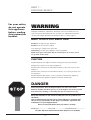
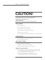
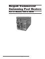
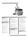
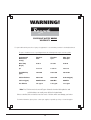
Raypak Commercial
Swimming Pool Heaters
Part 1: Safety warning
Part 2: Models 538 to 4224
Part 3: Warranty
CONTENTS
Part 1: For Your Safety
Part 2: Models 538 to 4224
Section 1. Installation Instructions
Section 2. Owners Operating
Instructions
Part 3: Warranty
Date of Installation:
//
//
Model No.
Serial No.
Installed by:
Purchased from:
This Installation and Operating Instructions Manual is
provided with the necessary information for the proper
installation, operation and maintenance of your Raypak
Heater. Please review and follow these procedures
carefully. Keep this manual in a safe and accessible place
for easy reference in the future.
3
PART 1 FOR YOUR SAFETY
For your safety
do not operate
this appliance
before reading
this instruction
booklet.
WARNING
Improper installation, adjustment, alteration, service or maintenance can
cause injury or property damage. For assistance or additional information
consult your Raypak distributor, qualified installer, or service agency.
WHAT TO DO IF YOU SMELL GAS?
DO NOT try to light any gas appliance
DO NOT touch any electrical switch.
Turn off the gas supply at the gas meter
Immediately, call your gas supplier or licensed gasfitter.
NOTE: Some gases are heavier than air and it may be necessary to check
for gas leaks at floor level.
CAUTION
DO NOT Operate this appliance before reading this instruction booklet.
DO NOT Place articles on or against appliance.
DO NOT Store chemicals or flammable materials in the same room as this
appliance.
DO NOT Store chemicals or flammable materials, on, or spray aerosols near
this appliance.
DO NOT Operate with panels, covers or guards removed from appliance.
DO NOT Enclose this appliance (applies to external models only).
DANGER
Water temperatures above 45 Degrees Celsius can cause severe burns.
Children, disabled and elderly persons are at the highest risk of being scalded.
Feel water before bathing or showering and supervise where necessary.
Keep this manual in a safe and accessible place for easy reference in
the future.
This Installation and Operating Instructions Manual is provided with
the necessary information for the proper installation, operation and
maintenance of your Raypak Heater.
Please review and follow these procedures carefully.
Model No. ..................... Serial No. .................... Installation Date ..................
Part No. 209130.5: Effective 08/01/2001 (Replaces: 01/10/2000)
4
PART 1 - FOR YOUR SAFETY
CAUTION!
Ceramic Firetile Refractory is used in Raypak Heaters
Possible risks of irreversible effects
Harmful by inhalation
May be irritating to the skin, eyes and respiratory system.
WHEN HANDLING
• Minimise airborne dust.
• Wear an approved mask or respirator.
• Avoid any contact with the skin and eyes.
• Wear suitable loose-fitting, long-sleeved clothing.
• Wear gloves and eye protection.
• Consult Occupational Health and Safety Authority for any further information.
AFTER HANDLING
• Rinse any exposed skin areas with clean water.
• Wash work clothing separately.
FIRST FIRING OF HEATER
• Fumes and smoke may be produced.
• Avoid breathing fumes, ventilate area to clear.
• Production of smoke should cease within 30 minutes
REMOVAL OF USED PRODUCT
• Wear an approved mask. Over-exposure to dust formed after service
may cause respiratory disease since cristobalite, a form of crystalline
silica may be formed above 900 degrees Celsius.
• Consult Occupational Health and Safety Authority for further
information regarding removal of used ceramic fibre linings.
5
Raypak Commercial
Swimming Pool Heaters
Part 2: Models 538 to 4224
6
PART 2 - SECTION I INSTALLATION INSTRUCTIONS
Before commencing installation:
1.
Read these instructions in full !
2.
Check that the heater you have
been supplied is suitable for the type of
installation and the gas available. The gas
supply pressure must be between the
minimum and maximum shown on the
heater data plate.
GENERAL
These instructions are provided to ensure the
correct installation and operation of your
Raypak Swimming Pool Heater.
Should any questions arise regarding the
specifications, installation, operation or
servicing of this heater, we suggest that the
local representative or Raypak Customer
Service be consulted.
Raypak heaters utilise a finned copper tube
heat exchanger resulting in a low water content
and reduced "stand by" heat losses. Therefore
a circulator pump of sufficient capacity to
match the heater model must be installed in
the system.
BEEN DAMAGED, WITHOUT FIRST
CONSULTING RAYPAK, AS ANY DAMAGE
OR FAULTS CAUSED BY UNAUTHORISED
START UP MAY NOT BE COVERED BY
OUR WARRANTY.
HEATER LOCATION AND
CLEARANCES
The heater should be located so that any
possible water leaks will not cause damage to
any adjacent areas or structures.
When such locations cannot be avoided, it is
recommended that a suitable drain pan,
adequately drained, be installed under the heater.
This pan must not restrict combustion air flow.
The heater must be mounted on a level noncombustible base such as a concrete slab,
concrete plinth, steel plate etc.
Raypak heaters and equipment must not be
installed on carpeting.
The front of the heater must not be obstructed
by any gas or water piping, electrical conduits,
trees, fences, or other equipment, etc.
A =1.5 X T
Where A = Minimum free ventilation area (cm2)
T = Total hourly input of all appliances (Mj/h)
Note: The minimum dimension of any opening
shall be 6mm.
Please take the heater location into account
when locating the fresh air vents because any
excessive draft will cause flame disturbance
and probable pilot outage. In some cases
where excessive draft effects the burner, the
risk of major damage is high due to
incomplete combustion.
Installations which obtain air from a source
other than directly from outside must comply
to AG601.
Warning: Air supply to the heater room
must not be affected by mechanical
exhaust vents located in other parts of
the house or building, such as kitchen or
bathroom fans, spa blowers, etc.
Mechanical exhaust vents may create a negative
pressure in the heater room that can become a
hazard by asphyxiation, explosion or fire.
Raypak heaters are fitted with Australian Gas
Association approved components and all
boilers in this range are designed to comply
to AG501.
Caution: Do not store chemicals or flammable
materials in the same room or near this
heater. Do not use aerosols near this heater
whilst it is in operation.
Some models are designed for either indoor or
outdoor installation subject to the appropriate
indoor draft hood or outdoor stackless top
being fitted.
FLUEING
The correct Draft hood must be fixed to the top
of the heater and connected to a properly
constructed flue, vented to the outside using
only approved fittings.
Check that the correct top for your installation
has been supplied.
INSTALLATION PROCEDURES
All electrical, gas piping, gas connection and
flueing of the heater must only be undertaken
by a properly authorised person. The
installation must comply with local gas, AG6012000 and electrical codes and/or statutory
body codes and regulations.
Raypak heaters must be installed in the
filtration system, in the pool return line,
downstream from the filter.
INSPECTION OF EQUIPMENT
Check the heater and associated equipment for any
damage and if so notify your local representative or
Raypak for any further instructions.
DO NOT INSTALL OR START UP ANY
RAYPAK SUPPLIED PRODUCT THAT HAS
COMBUSTION/VENTILATION
AIR
Indoor model heaters must only be installed in
a protective enclosure or properly constructed
plant room with adequate ventilation in
accordance with AG 601 - 2000 Gas
Installation Code.
Ventilation shall be via 2 permanent openings
directly to outside, one at an upper level and
one at low level.
The minimum free area provided by each vent
shall be as calculated by using the following
formula, unless otherwise stated in AG 601.
7
Reduction of the flue diameter or alteration to
the draft hood voids all warranty. Where
flueing may be difficult, please contact Raypak
for advice, we will have solutions, particularly
where a fan assisted flue may be the answer.
The weight of the flue must not rest on the
heater draft diverter, the flue must be self
supporting and be fitted with a disconnection
section (bolted sleeve) to enable the heater top
and draft diverter to be removed easily, for
servicing. Where practicable the flue should run
vertically. Lateral (raised above horizontal) is
acceptable but the run of a flue shall not
exceed 50% of total flue height and shall be
designed to rise not less than 20 mm per 1 m
run. The flue must be terminated with an
approved cowl.
PART 2 - SECTION I - INSTALLATION INSTRUCTIONS
Raypak recommends a minimum length of
vertical flue of three (3) metres to ensure
correct draft.
AGA Approved Cowl
Distance above roof must be
as stated in AG601
Minimum
flue length
3 metres
Self-supporting flue
Bolted sleeve
HIGH WIND CONDITIONS
On rare occasions or in areas where high
winds frequently occur, it may be necessary to
locate the heater a minimum of one (1) metre
from high vertical walls, or install a wind break
so that the heater is not in direct wind current.
Models 538 to 1852, where the installation
may cause "Down draft", Raypak can supply a
Wind Deflection Plate (at extra cost), to
eliminate constant ignition failures or flame
disturbance, the need for which would be
determined by an approved Raypak Service
Person or Agent.
Wind Deflection Plate
Correct draft converter
(Indoor hood)
Prevailing
Winds
When installing the heater on a raised base,
please make sure that the base material is
solid and filled in. E.G. If steel mesh decking is
used, a suitable plate material must be used to
fill in the perforations. This is very important, as
any excessive drafts must not be able to enter
the unit from directly underneath.
Failure to follow this procedure may result
in damage to the gas valve. (Over
pressured valves and equipment are not
covered by our warranty.)
The heater and it's gas connection must be
thoroughly leak tested before placing in
operation. Use soapy water and a manometer
for leak test.
DO NOT USE NAKED FLAME.
The heater must be installed to the appropriate
and/or local codes. For typical piping systems
and heater applications it is essential that
Raypak be consulted, Raypak heaters do have
some special requirements and if you are not
familiar with Raypak products we can save you
unnecessary inconvenience!
High Wind Windbreak
An outdoor heater must not be installed inside
any roofed structure or under eaves, roof
overhangs, or pool decks. It should also be at
least 1500 mm, in any direction from any
window or fresh air opening.
Dissipate test pressure before reconnecting to
the heater.
WATER CONNECTIONS AND
SYSTEM PIPING
Heater
OUTDOOR INSTALLATIONS.
Caution: The gas supply must be isolated from
the heater during pressure testing of the gas
fitting line.
In areas of "constant extreme winds" or where
a Wind Deflection Plate is not appropriate, it
may be necessary to replace the "standard"
low profile outdoor hood with a HIGH WIND TOP
which would be at extra cost.
The HIGH WIND TOP serves the same function
as the low profile outdoor hood and should be
installed in accordance with the same
clearance requirements.
Water pipe connections to heater are:
538 to 1292 - 50 mm copper slip fit or 2" NPT,
1362 to 1922 - 80mm BSP and
2004 to 4224 - 100 mm BSP.
Do not reduce the pipework size and heater
water connections without allowing for any
friction loss which will occur. Low water flow
will cause damage to the heater and system
components. Please install pipework using
approved fittings and isolating valves that will
allow easy disconnection for any future
maintenance requirements.
HIGH WIND TOP
Water
Connections
Gas
Connection
610 mm
This area must be
filled in
• On large elevated
decks fill in to at
least one metre all
around unit
Use a minimum of one (1) metre of copper or
stainless steel tube for the final connections to
the heater inlet and outlet.
GAS SUPPLY
Elevated Deck
The gas supply pipe must be sized to give
sufficient pressure for the correct operation
of the heater. The gas line must be fitted
with an isolation valve. Consult AG 601 for
further details.
8
NEVER CONNECT LOW TEMPERATURE PVC
PRESSURE PIPE DIRECTLY TO THE HEATER.
A non-return valve must be installed on the
inlet side of the heater, after the filter.
PART 2 - SECTION I - INSTALLATION INSTRUCTIONS
PUMP SELECTION
The filtration pump must be sized to provide an
adequate water flow for the filtration system
and the heater. In some cases however, this
can cause a high back pressure which reduces
the filtration capacity and in this case it would
be more of on advantage to install an additional
pump for the heater only. This pump must be
installed on the inlet side.
DO NOT connect the pump to the heater outlet.
Some heater models incorporate their own ByPass Pump but this is used to control the
temperature of the water entering the heater to
prevent condensation and scale and will not be
suitable as the additional pump described above.
SYSTEM OVER TEMPERATURE
CUT OUT
The installation may require a "System Manual Reset High Limit", refer to AG601 and
other relevant codes.
AUTOMATIC CHEMICAL
DOSING EQUIPMENT
All automatic chemical dosing devices,
including salt chlorination, MUST be installed
downstream of the heater and in a manner that
will not allow the chemically dosed solution to
enter the heater before being thoroughly mixed
with the main pool or spa water.
PRESSURE RELIEF VALVE
Refer to the Flow Rate chart following when
sizing the pump.
The standard pressure relief valve supplied is
set to 410 kPa (60 PSI).
Where the water flow rate exceeds the
maximum shown in the chart, a by pass valve
must be installed to reduce the water flow
through the heater.
WATER SENSOR LOCATION
A pump run on timer must be fitted to remove
any residual heat from the boiler and prevent
any nuisance tripping of the high limit switch.
WATER FLOW RATES.
Model
538 to 1292
1362 / 1412
1492 / 1552
1662 / 1722
1852 / 1922
2004 / 2214
2404 / 2634
2804 / 3164
3304 / 3694
3804 / 4224
On models 1362 to 4224, where a By-Pass
pump is an integral part of the heater, the
water sensor of the Digital Thermostat is
supplied with the unit but it is not installed to
the pipework.
Please insert the sensor as shown in the
drawing below.
Water flow (l/sec)
ELECTRICAL WIRING
min
max
4.5
1.9
2.2
2.5
2.8
3.2
3.8
4.7
5.6
6.2
7.5
3.2
3.5
4.1
4.4
5.0
5.9
7.2
8.4
9.4
The electrical power consumption of the
heaters is:
Models 538 - 1292 (No By-Pass Pump):
240 Volts AC, 50/60 Hz, 100 VA approx.
Models 1362 - 1922 (UPS 32-80B By-Pass Pump):
240 Volts AC, 50 Hz, 1.4 Amps approx.
Models 2004 - 3164 (UMT 50-30Z By-Pass Pump):
240 Volts AC, 50 Hz, 3.0 Amps approx.
Models3304 - 4224 (UMT 50-60Z By-Pass Pump):
240 Volts AC, 50 Hz, 3.0 Amps approx.
A normal 10 or 15 Amp, single phase power
circuit would be suitable.
We recommend that the pump be selected that
will deliver the maximum flow and the
installation of an external by-pass in all cases so
as to allow for the field adjustment if required.
Access to the electricals is achieved by
removing the cover of the control panel. (See
Location of Controls for different models.)
IMPORTANT: When installing a new heater
to an old system, it is a Raypak
requirement that the system and its
equipment be inspected and if necessary,
drained and flushed out with clean fresh
water, before the new heater is
connected. Failure to do this may cause
blockages and/or heater damage which is
NOT COVERED BY WARRANTY and any
damage caused would result in extra
costs to repair etc.
THE HEATER MUST NOT BE ABLE TO
OPERATE WITHOUT THE CIRCULATING
WATER PUMP RUNNING.
IF THERE IS ANY DOUBTS ABOUT SYSTEM,
DRAIN AND FLUSH AS A PRECAUTION.
The heater must be properly earthed and
Raypak highly recommends the installation of
an RCD (Residual Current Device) for added
electrical safety. If the site is "electrically
noisy", a mains filter can be supplied at extra
cost, to eliminate failures.
The heater (240 Volts) power supply must be
"interlocked" via the auxiliary contacts of the
pump contactor (relay) etc or alternatively the
power supply for the pump and the heater
must operate off the same circuit and isolation
switch. (Parallel connection)
9
A Flow Switch is not regarded as an
interlock and must not be used as one.
Any other form of interlocking must be
approved by Raypak.
A pump run on timer is required so that at any
time that the heater is no longer required, the
heater shuts off and the pump continues for at
least ten (10) minutes.
A Raypak "economaster" is an optional extra
available at extra cost for all heaters.
For servicing purposes we suggest that the
isolation switch be installed as near as
practical to the heater.
If there is any control wiring etc which is not
isolated by this switch then a suitable warning
label must be affixed to the heater which will
also direct the service person to the isolation
switch for that particular wiring. E.G. More than
one isolation switch is required to turn off the
power supply, Extra switch(es) on switchboard
etc.
Caution: Do not locate cables in front of or
underneath the burner, please consult Raypak
for advice if unsure.
Where cables or conduit, trunking etc are to be
mounted on the heater casing, please keep at
least 10mm air gap from the heater casing to
eliminate possible overheating.
Do not locate cables etc where they will
restrict access covers, doors etc.
Where the clearance from the right hand side
of the heater (models 538 to 1922) is
restrictive, please notify Raypak at the time of
manufacture and we may be able to relocate
the control panel for a minimal extra cost, if
this is not possible then a field retrofit may be
the best solution. (At extra cost)
There are many variations to the types of
controls available and also RUN & FAIL indication
can be supplied. Ask Raypak what is available.
PART 2 - SECTION I - INSTALLATION INSTRUCTIONS
COMMISSIONING
WARNING: COMMISSIONING MUST ONLY BE
UNDERTAKEN BY A PROPERLY AUTHORISED
AND IN SOME CASES APPROPRIATELY
LICENSED PERSON WHO IS FAMILIAR WITH
SAFE COMMISSIONING PROCEDURES. THE
COMMISSIONING MAY REQUIRE
INSPECTION BY THE GAS SUPPLY
AUTHORITY, CHECK IF THIS IS APPLICABLE.
RECOMMENDED
COMMISSIONING PROCEDURE.
1. Check that all necessary approvals and
appropriate documents have been obtained.
2. Ensure that the heater is clean and the
surrounding area is clear of all combustible and
flammable materials.
3. Remove all liquids and chemicals from the
plant room and check that combustion air
openings are not obstructed. Chemicals must not
be stored in the plant room - this is extremely
dangerous and may damage the heater.
4. Fill the system with water and expel any air
as required.
5. Purge all air from gas supply piping.
CAUTION: Liquid Propane Gas is heavier than
air and sinks to the ground, exercise extreme
care in lighting boiler in confined areas.
6. Test ALL gas connections for leaks, using
soapy water and a manometer.
(NOT A NAKED FLAME)
7. Conduct a visual inspection of the heater
and equipment for any damage or installation
problems and report as necessary.
8. Check that the correct power supply is
available and the circulation pump is
electrically interlocked with the heater.
9. Check that the ventilation to the plant room
complies with Raypak requirements, AG601
and local authority regulations.
If mechanical ventilation is provided, check its
operation and any interlocks.
10. Check that the flue complies with the
appropriate regulations and is fitted with an
approved termination cowl.
11. Check that the gas supply is isolated and
with the main gas valve isolation switch turned
off, check the boiler gas train and components
for gas escapes.
12. Start the circulation pump and verify the
pressure switch operation, then test the
operation of the heater with no gas flow to
confirm its operation up to the lockout status.
Pressure switch adjustment is required if the
unit won’t fire and after faultfinding it is verified
that the pressure switch has not closed.
Adjust the pressure setting at the thumbwheel
to a lower setting, then re start the heater.
If the heater fires up but won’t shutdown when
the water is reduced then it will require
adjustment to the thumbwheel to a
higher setting and the heater restarted.
(In some cases the electrical interlock between
the pump and heater may require a temporary
disconnection to carry out tests.)
13. Open the gas supply valve, switch on the
main valve isolation switch and reset the
ignition control to fire the heater.
14. When the unit fires and reaches high fire,
set the burner gas pressure to that shown on
the data plate which is located on
the front of the heater.
15. Verify that the high limit and any other
safety devices are operating correctly.
16. Check the water temperature rise of the
heater and adjust the water flow as necessary.
For models 538-1292, measure the
temperature difference between the Inlet and
Outlet pipes at the heater, with the unit at full
fire.
The difference should be approximately 5 - 10
Deg. C.
If it is lower than recommended, decrease the
water flow through the heater.
If it is higher than recommended it indicates
that the water flow rate is too low.
For models 1362 to 4224, the temperature
gauges which are fitted to the heater can be
used as a guide.
The objective is to maintain a temperature of
approximately 50 Deg C at the outlet side of
the heater, 30 Deg C at the inlet side, with the
unit at full fire.
10
The digital display on the electronic thermostat
will indicate the pool water temperature.
17. Check that the flue is operating correctly
or if there is evidence of Down draft etc report
as necessary.
18. Check operation of any water pressure
relief valves etc and set up the controls to
desired settings.
19. Ensure that the customer is supplied with
this manual and you have demonstrated the
operation of the unit etc.
It is quite normal for the heater to produce
some smoke and possible condensation for the
first thirty (30) minutes of firing from new.
WARNING - Should overheating occur or the
gas fail to shut off, turn off the gas isolation
valve adjacent to the heater and then
examine the unit or call for assistance.
SECTION II OPERATING INSTRUCTIONS
WHAT IF YOU CAN
SMELL GAS?
Always keep the heater clean and the
surrounding area clear of all combustible and
flammable materials.
If you do not smell any gas continue ...
SAFETY INSTRUCTIONS
Remove all dangerous liquids and chemicals
from the plant room and check that the
combustion air openings are not obstructed.
Don’t attempt to light the burner by hand.
• DON’T TRY TO LIGHT ANY
GAS APPLIANCE.
• DON’T TOUCH OR OPERATE ANY
ELECTRICAL SWITCH.
Chemicals must not be stored in plant room.
This is extremely dangerous and also very
damaging to the heater.
• TURN OFF THE GAS SUPPLY AT THE
GAS METER OR ISOLATION POINT.
If you don't know what to do.
• CALL YOUR GAS SUPPLIER OR
QUALIFIED GASFITTER FROM A
NEIGHBOUR’S TELEPHONE.
LIGHTING
PROCEDURE.
Use only your hand to turn the pilot gas control
knob. Never use any tools.
If the knob will not turn by hand do not try to
repair it, call a qualified service technician.
Force or attempted repair may result in a fire or
explosion.
Do not use this heater if any part has been
under water.
Call a qualified service technician immediately
to replace any part or control system that has
been under water.
TO TURN OFF
THE HEATER
1. Turn the heater ON/OFF power
isolation switch to the "OFF" position.
EMERGENCY SHUT-DOWN
1. Turn "OFF" the power supply to the heater
2. Turn "OFF" the gas isolation valve fitted
close to the heater or the main gas supply.
AFTER START-UP WARNING
Should overheating occur or the gas supply fail
to shut off, turn off the gas isolation valve
located adjacent to the heater turn off the
power supply switch and call for assistance.
VISUAL INSPECTION FOR DANGER!
Keep the heater area free from chemicals,
combustibles and flammable materials.
Do not obstruct the flow of ventilation air into
the plant room.
Regularly clean the heater cabinet air louvres of
any dust, lint and debris.
Ring for assistance.
1. STOP read the safety information.
2. Turn heater ON/OFF power isolation
switch to the "OFF" position.
3. Turn "OFF" any other electrical
power to the heater. (If required)
4. Turn the gas supply valve, fitted next to the
heater "OFF".
5. Wait 5 minutes to clear out any gas.
6. This heater is equipped with an ignition
device that automatically lights the burners.
7. Turn the gas supply valve to the "ON"
position.
8. Turn on all electrical power to the
heater. (If required)
9. Set the thermostat or temperature
control to the desired temperature
setting and turn the heater ON/OFF
switch to the ON position.
10. The heater will go through its light up
sequence.
If the heater fails and the "red" reset light
illuminates, turn off the power supply, wait one
(1) minute, turn the power supply back on and
when the reset illuminates again, push the
reset button, which will turn off the fail light
and restart the light up sequence.
If heater still does not light, turn off gas and
power supply and contact your qualified
service technician.
STOP!
If you smell gas, follow safety instructions.
Failure to follow these safety precautions can
cause fire, explosion, or asphyxiation.
With the heater turned on and heating, remove
the door (if fitted) and make a visual check of
the burners. The flame should be blue with a
well-defined pattern.
A yellow or floating flame indicates restricted air
openings, incorrect orifice size or possible
excessive draft. Continual yellow flames indicate
some restriction of the combustion air openings.
A bright orange, luminous flame is not normal and
can cause sooting under prolonged operation.
Observe for any indication of soot. The
presence of soot accumulation would indicate
an abnormal operating condition.
Should any abnormalities occur, turn the
heater off and contact your installer or
service organisation.
WARNING: Operation of the heater when faulty
will result in rapid and severe damage to the
heater, which is not covered by our warranty.
11
SERVICE ASSISTANCE
Service must only be undertaken by properly
authorised personnel.
It is a requirement of all Raypak and all gas
authorities that the heater be serviced at least
once per year, where it is used in a specific
application, e.g. heating, it would be practical
to perform the service at the commencement
of the heating season, or at any time there may
be an indication of a problem.
This service should include the cleaning of the
gas burners, inspection of waterways, and
checking of all controls for correct operation.
It is important and very often will save time if
you state the model number, serial number and
type of gas used. This information will be found
on the heater data plate.
Your local Raypak distributor will arrange for
your service or recommend a qualified
service organisation or visit:
www.raypak.com.au
PART 2 - SECTION II - OPERATING INSTRUCTIONS
LOCATION OF CONTROLS
FLOW SWITCH (ON SOME MODELS ONLY)
MODELS 2214, 2634, 3164, 3694, 4224
MODELS 538 TO 2004, 2404, 2804, 3304, 3804
1. Flame Fail Reset (Illuminates on FAIL) 2. Alarm Fail & Mute Button (if fitted)
3. Alarm Siren (if fitted) 4. Temperature Control (Digital Thermostat)
1. FLAME FAILURE RESET:
This is a combination rest button
and indicator lamp. It indicates,
when illuminated, that the ignition
system has shutdown on its safety
control.
2. ALARM FAIL &
MUTE BUTTON:
This is an optional extra, which will
illuminate when the heater has
generally failed to operate on its
safety controls. The circuitry
activates an audible alarm on fail,
which can be silenced by pressing
the reset button, however the light
will remain illuminated until the
cause of the failure has been reset.
4. TEMPERATURE CONTROL:
Digital type thermostat with
pushbutton adjustment.
12
3. ALARM SIREN:
This is used in conjunction with the
optional extra, ALARM FAIL system
and emits a high pitched "warble"
when activated.
PART 2 - SECTION II - OPERATING INSTRUCTIONS
LOCATION OF CONTROLS
RL1
MTR12
INSTRUCTIONS FOR USE OF
LAE ELECTRONIC
THERMOSTATS.
Raypak uses the MTR12T1RES series
thermostats which is programmed to operate in
the heating mode.
The only adjustments that should normally be
required are:Set point (set):Which is the water
temperature that you require.
Differential (hys): - Which is the difference
between the thermostat turning OFF and then
ON again when the temperature has fallen.
eg. 1ºC would be ideal for controlling a
swimming pool.
To Adjust the Set Point:• Turn on the power supply to the heater.
•The Digital display will show the actual water
temperature.
To Adjust the differential:-
rt1-(RL1 Rest Time) 0 min
• Turn on the power supply to the heater.
- there is no delay in relay operation.
• The Digital Display will show the actual water
temperature.
PF1-(Probe Failure) OFF
• Press the "hys" button, HY1 will be displayed
for 2 seconds.
ADJ-(Probe Offset) 0 Deg. C
• Then the value will be displayed. ( It must be
a negative value. )
- the relay operates on actual temperature of
the sensor.
• Press the "UP" or "DOWN" button to set your
desired differential
HY1-(Mode) -25
• This is adjustable from - 1 to -25 which
relates to 1 to 25 Deg. C.
LAE ELECTRONIC
THERMOSTAT DEFAULT
SETTINGS.
Raypak may have programmed this thermostat
to avoid any "nuisance" failures as:vSP-(Min Set Point) 0ºC
• Press the "set" button, L1 will be displayed
for 2 seconds.
- the heater won’t operate if the water
temperature is below this setting.
• Then the Set Point temperature will be
displayed.
^SP-(Max Set Point) 40 Deg. C
• By pressing the "UP" or "DOWN" button, you
can set the desired temperature.
- if the Probe (water sensor) fails, the relay will
turn off the heater..
- the device turns off the heater if the water
temperature exceeds this setting.
13
- the negative value programs the device for
heating.
TAMPER PROOF SETTINGS.
Decide what values for the set point and the
differential suits the application. Adjust the
program so that "vSP & ^SP" are the same
value as the set point and adjust the program
so that "HY1" is the same value as the
differential. The operator now cannot adjust the
settings, however this is not totally foilproof, as
re-programming is still possible. For total
protection against tampering, fit a locked or
anchored cover over the thermostat buttons.
PART 2 - SECTION II - OPERATING INSTRUCTIONS
MODELS WHICH ARE
CONNECTED TO A MICROZONE
SYSTEM
If the heater(s) are operated by a Microzone
system, there will be a rotary type control knob
fitted which should be aligned to the desired
temperature.
WATER TREATMENT
For your health and the protection of your pool
equipment it is absolutely essential that your
pool water is chemically balanced.
WARRANTY PROCEDURE FOR
WATER LEAKS FROM HEAT
EXCHANGER.
HIGH LIMIT SWITCH.
ALL heaters are fitted with a manual reset high
limit switch. This control will shut down the heater
in the event of a fault with the temperature control
and/or overheat of the system.
This setting will vary, depending on the type of
system being used but must not be too close to
the operating temperature, as nuisance tripping
will occur.
The usual setting is approximately 60 - 65 ºC
To set the Honeywell L6188C High Limit,
remove Philips Head screw next to red reset
button, remove lighter grey cover, pull out
darker grey top cover to reveal adjustment.
CORROSIVE WATER
VOIDS ALL
WARRANTIES!
1. The service technician inspects the tube
bundle, if the water leak is through one or
more pinholes (usually caused by corrosion)
then the warranty is voided and therefore any
repairs will be paid for by the owner.
2. If the service technician deems that the
water leak is not caused by corrosion, the
14
technician can replace the faulty parts at the
technician’s risk. Raypak will supply the new
components, the service technician will pay all
charges and then there may be a refund when
the parts have been returned to Raypak and we
have agreed that the warranty is applicable.
3. If there is an objection to this policy, we
suggest that the faulty components be
submitted to an independent testing facility for
analysis, at the customer’s expense. If the
testing facility deems that the leaking was
caused by a manufacturing defect, on
production of the official report and details of
costs, Raypak will refund all relevant expenses
incurred by the customer.
PART2 - SECTION II - OPERATING INSTRUCTIONS
RECOMMENDED SERVICE
PROCEDURES
It is a Raypak requirement that all Raypak
supplied equipment is serviced at least
annually.
In some installations, due to the appliance
location and/or workload it may be necessary
to perform a service every six months.
RECOMMENDED SERVICE
PROCEDURE FOR ANNUAL
SERVICE.
• Isolate gas, electricity and water as required.
• Remove access covers and door(s) as
required.
• Disconnect and remove Burner Tray.
• Dismantle and clean pilot assembly(ies),
including injector(s).
• Clean and re-align electrode(s) and/or flame
rod(s) and /or thermocouple(s).
• Clean main burner injectors and burner bars
as required.
• Inspect, repair if minor and clean
combustion chamber.
• Report on any major combustion chamber
damage.
• Inspect external area of heat exchanger,
clean fins and repair if minor.
• Check water seal area and report any
damage.
• Operate Pressure Relief Valve (if Fitted)
manually to check that the drain is clear and
the valve reseals.
operation if needed.
• Pool Heater: Remove and test Unitherm
Governor(s), replace if faulty.
• Check over the appliance thoroughly and
report any damage immediately.
• Refit Burner Tray and reconnect gas train etc.
• Pool Heater: Remove and test Unitherm
Governor(s), - (if faulty, Unitherm must be
replaced before re-commissioning appliance).
• Perform gas soundness tests to the gas train.
(Any failures must be reported and repaired
before recommissioning appliance.)
• Check all air vents and louvres, clean as
required.
• If necessary, remove Burner Tray and service
as required. (Refer to Annual Service).
• Check the heat exchanger and water seal
areas and report any damage, if necessary.
• Restore gas, electricity and water as required.
• Check air vents and louvres, clean as
required.
• Recommission unit, check and prove the
operation of all safety devices.
• Check operation of ignition system and all
safety devices.
• Check and monitor the operation of the
appliance for at least ten (10) minutes.
• Check operation and calibration of all
temperature control devices.
• Refit access covers and doors as required.
• Check operation (and monitor the operation)
of appliance for at least ten (10) minutes.
• Clear and remove any dust and debris from
the appliance and its immediate area.
• Refit access covers and doors as required.
RECOMMENDED SERVICE
PROCEDURE FOR SIX
MONTHLY SERVICE.
• Isolate gas, electricity and water as required.
• Remove access covers and doors as
required.
• Restore the gas, electricity and water as
required.
• Visually inspect main burner and pilot, check
15
• Clean and remove any dust and debris from
the appliance and its immediate area.
ONLY A SUITABLY LICENSED PERSON
MAY PERFORM ANY REPAIRS,
SERVICE AND/OR COMMISSIONING OF
GAS APPLIANCES.
WARNING!
CORROSIVE WATER VOIDS
WARRANTY
For your health and the protection of your pool equipment, it is essential that your water is chemically balanced.
For years of trouble-free use of your Raypak heater, the following levels may be used as a guide:
Recommended
Maintenance
Level(s)
Fibreglass
Pools
Fibreglass
Spas
Other Types
Pools/Spas
Water Temp
(Deg C)
20 to 31
32 to 40
20 to 40
pH
7.3 to 7.4
7.3 to 7.4
7.6 to 7.8
Total Alkalinity
(ppm)
120 to150
120 to 150
150 to 200
Calcium Hardness
200 to 300
150 to 200
80 to 100 (ppm)
Salt Level (ppm)
6000 Maximum
6000 Max
6000 Max
Free Chlorine
2 to 3 ppm
2 to 3 ppm
2 to 3 ppm
Note: Free Chlorine must not exceed 5 ppm. Automatic chemical dosing devices and
salt chlorinators are usually more efficient in heated water.
Unless controlled, this can lead to excessive levels of chlorine which can damage your heater.
For further information, please please contact your supplier, a reputable pool shop or chemical supplier.
16
PART 4 WARRANTY
RAYPAK WARRANTY
FOR COMMERCIAL
SWIMMING POOL
HEATERS.
Raypak Australia Pty Ltd* will:
a) repair or, if necessary, replace any Raypak
pool heater; or
b) replace any component (or, if necessary,
arrange the installation of a new pool heater),
which falls within the Warranty Periods
specified below, in accordance with and subject
to the following table and terms and conditions.
Component and Heat Exchanger Warranty
(From Date of Installation)
Period
12 Months
Installation
All Installations
Model
P0538 - P4224
Warranty
New component, tube bundle
or heat exchanger (at Raypaks sole discretion)
free of charge, including labour**
Notes:
* Rheem Australia Pty Ltd provides warranty
service on behalf of Raypak Australia Pty Ltd.
**Refer to item 5 of warranty conditions.
Raypak Australia Pty Ltd reserves the right to
transfer fully functional components from the
defective pool heater to the replacement pool
heater if required.
WARRANTY CONDITIONS
1. This warranty is applicable only to pool
heaters manufactured from 1st August 2002.
2. The pool heater must be correctly
commissioned by an authorised and licensed
person and certified by the relevant State
Gas Authority.
3. The pool heater must be installed in
accordance with the Raypak installation
instructions, supplied with the pool heater, and
in accordance with all relevant statutory and
local requirements of the State in which the
pool heater is to be installed.
4. Where a failed component or pool heater is
replaced under Warranty, the balance of the
original warranty period will remain effective.
The replaced part or pool heater does not carry
a new warranty.
5. Where the pool heater is installed outside
the boundaries of a metropolitan area as
defined by Rheem Australia Pty Ltd or further
than 25 km from a regional Rheem branch
office or a Rheem Accredited Service Agent,
the costs of transport, insurance and travelling
between the nearest Rheem Australia Pty Ltd
Accredited Service Agent’s premises and the
installed site shall be the owner’s responsibility.
6. The warranty only applies to the pool
heater and original or genuine (company)
component replacement parts and therefore
does not cover any plumbing or electrical parts
supplied by the installer and not an integral
part of the pool heater, eg. pressure limiting
valve, stop cock, non-return valve, electrical
switches, pumps, or fuse.
7. The pool heater must be sized to supply
the hot water demand in accordance with the
guidelines in Raypak Pool Heater literature.
WARRANTY EXCLUSIONS
1. REPAIR AND REPLACEMENT WORK WILL
BE CARRIED OUT AS SET OUT IN THE RAYPAK
POOL HEATER WARRANTY ABOVE, BUT THE
FOLLOWING EXCLUSIONS MAY CAUSE THE
POOL HEATER WARRANTY TO BECOME VOID,
AND MAY INCUR A SERVICE CHARGE AND/OR
COST OF PARTS.
a) Accidental damage to the pool heater or
any component, including: acts of God, failure
due to misuse; incorrect installation; attempts to
repair the pool heater other than by a Rheem
Accredited Service Agent or Rheem Service.
b) Where it is found there is nothing wrong
with the pool heater, where the complaint is
related to excessive discharge from the
pressure relief valve due to high water
pressure; where there is no flow of water due
to faulty plumbing; where water leaks are
related to plumbing and not the pool heater
components; where there is a failure of gas,
electricity or water supplies; where the supply
of gas, electricity or water does not comply
with relevant codes or acts.
c) Where the pool heater or pool heater
component failed directly as a result of;
excessive water pressure, temperature and/or
thermal input; incorrect flow rate through the
heat exchanger; corrosive atmosphere.
d) Where the pool heater is located in a
position that does not comply with the
17
Raypak installation instructions or relevant
statutory requirements, causing the need for
major dismantling or removal of cupboards,
doors or walls, or use of special equipment to
bring the pool heater to floor level, or to a
serviceable position.
e) Repairs to the pool heater due to
corrosion or scale formation in the waterways
where the pool water chemistry is outside the
guidelines detailed in the Operating and
Installation Instructions.
2. SUBJECT TO ANY STATUTORY PROVISIONS
TO THE CONTRARY, THIS WARRANTY EXCLUDES
ANY AND ALL CLAIMS FOR DAMAGE TO
FURNITURE, WALLS, FOUNDATIONS OR ANY
OTHER CONSEQUENTIAL LOSS EITHER
DIRECTLY OR INDIRECTLY DUE TO LEAKAGE
FROM THE POOL HEATER.
In addition to this warranty, the Trade Practices
Act 1974 and similar laws in each state and
territory provide the owner under certain
circumstances with certain minimum statutory
rights in relation to your Raypak pool heater.
This warranty must be read subject to that
legislation and nothing in this warranty has the
effect of excluding, restricting or modifying
those rights.
FOR SERVICE TELEPHONE
Raypak Australia Pty Ltd
A.B.N. 65 078 743 414
131 031 AUSTRALIA
0800 657 335 NEW ZEALAND
or refer to local Yellow Pages
NOTE: Every care has been taken to ensure
accuracy in preparation of this publication. No
liability can be accepted for any consequences,
which may arise as a result of its application .
NOTES
18
Manufactured by
Raypak Australia
7 Geddes St.
Mulgrave Vic 3170
Ph. (03) 9535 3333
Fax (03) 9560 4974
JAN 2003
Quality System
RHEEM SERVICE 131 031
WWW.RHEEM.COM.AU
Quality
Endorsed
Company
P/NO 96209131