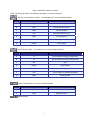
1
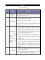
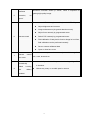
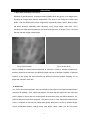
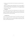
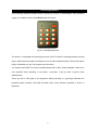
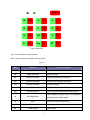
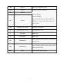
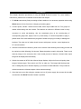
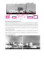
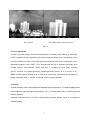
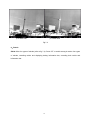
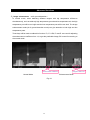
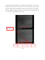
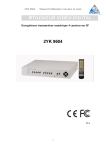
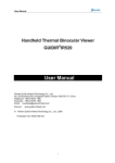
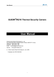
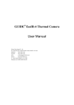
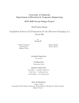
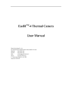
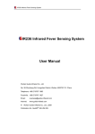
IR136 Thermal Camera
User Manual
Wuhan Guide Infrared Technology Co., Ltd.
No. 26 Shucheng Rd, Hongshan Dist, Wuhan 430070 P. R. China
Telephone: +86-27-8767 1926
Facsimile: +86-27-8767 1927
Email: [email protected]
Internet:
www.guide-infared.com
© Wuhan Guide Infrared Technology Co., Ltd., 2004
Publication No: IR136 UM 006
1
Contents
Precautions……………………………………………………………………………………………3
Introduction……………………………………………………………………………………………5
Features………………………………………………………………………………………………..7
Annotation ……………………………………………………………………………………………9
Controlling keyboard ………………………………………………………………………………11
Procedures……………………………………………………………………………………………14
Basic functions ……………………………………………………………………………………..15
Advanced functions………………………………………………………………………………...19
Quick trouble shooting…………………………………………………………………………….20
2
Precautions
All User Manuals and leaflets should be read thoroughly before proceeding with operation of the
equipment
It is also advisable that all User Manuals and Instruction Leaflets supplied are kept readily available,
for reference when the equipment is in general use
The following precautions must be adhered to at all times and must be considered in addition to any
advised precautions issued at the relevant worksite or work area
•
Do not supply power to IR136 Thermal Camera beyond the followed requirement:
DC +24V(±1V)
AC 110V-240V, 50-60 Hz, power rate≥50W
•
You will use PC, monitor, power and etc with IR136 Thermal Camera, so it is highly
recommended to connect all the electric systems with ground
•
It is highly recommended to use IR136 Thermal Camera statically although it is static
protected. By this, to avoid any damage to the precise electronics inside the camera
•
Do not frequently power on/off the camera. Time between on and off should be not less
than 30 sec.
•
Do not pull in/out power cord, video cable, control cable etc. when the camera is on; And
highly recommended to cut off power of all the connected electric systems like monitor
when pulling in/out all the cables.
•
Do not direct the IR136 Thermal Camera at very high intensity radiation sources such as the
sun, carbon dioxide lasers or arc welders etc
•
Do follow the environmental conditions as follows:
Storage Temp: -45℃ ~ 65℃
Work Temp: -40℃ ~ 55℃
Vibration: 5-500 Hz, 12.7mm peak
Shock: 20G, 11ms
3
The IR136 Thermal Camera does not incorporate any user serviceable parts. Never attempt
to disassemble or modify the camera. Opening the unit invalidates the warranty
•
Do not loose the bolts on the bottom of the camera, to avoid any effect on the detection and
image.
•
Do not use thinner to clean the camera parts, especially the optical part.
•
Please power off the camera if you will not use the camera for a while.
4
Introduction
IR136 Thermal Camera is a long range camera used for anti-aircraft and surveillance
application. Based on general IR technology, and integrated Guide unique research, IR136 is a
thermal Camera is with several optimized solutions.
IR object lens
Programmed lens cover
Interfaces
IR module
IR lens
Fig 2-1 IR136 Thermal Camera
Interfaces
Power button
Air tap
5
Fig 2-2 Interfaces at back of camera
Note: The air tap is used for air loading and sealing, not user-access part
RS-232 communication / Video,The definition for 9-core is listed as follows:
No
Definition
Description
A
TXD
RS-232 sending-end
B
RXD
RS-232 Receiving-end
C
GND
RS-232 ground
D
+8V
External power for LCD
E
GND
Power-ground
F
GND
G
VIDEO
Video-ground
Video signal
RS-422 control / video,The definition for 7-core is listed as follows:
No
Definition
Description
A
A
RS-422 data receiving in-phase end
B
B
RS-422 data receiving out-phase end
C
NC
Null
D
VIDEO
Video signal
E
GND
Video-ground
F
+8V
Power supply for external keyboard
G
GND
Power-ground
Power, The definition for 5-core is listed as follows:
No.
Definition
Description
B
+24V
Positive power
E
GND
Negative power
Internal debug
6
Features
Fig 3-1 IR136 Features
No.
1
2
Technical
Specifications
Description
Long detection
High detection sensitivity ensured by micro-cooling technology
range
and multi-level object lens system
Switch FOV fast
z
Built-in double focus IR lens system
z
Switch FOV fast by remote control
z
Search target in wide FOV and accurate sighting in narrow
FOV
z
When detecting high altitude, low altitude and ground
simultaneously with big temperature difference, in order to
keep high sensitivity, the temperature part will be too white
Auto-adjusted air
&
detection
3
and low temperature part will be too dark.
ground
mode
z
temperature area of high altitude can’t be detected. It is really
(image
enhancement
removing
Target in high temperature area of low altitude and low
dangerous.
by
low
z
Auto-adjusted sky & ground detection mode enables soldiers
see any object within any temperature area under any of
frequency)
above described conditions simultaneously. This mode is
extremely important for specialized anti-aircraft infrared
thermal
4
Auto calibration
z
Correction and calibration of the camera can be done by
built-in programmed shutter.
z
No extra manual work needed for calibration, such as covering
the lens cover or finding clean and cloud-free sky
7
Nonlinear correction clears up “Ghost”, which is important for
Nonlinear
5
correction,
no
getting high-quality image.
“ghost”
Remote control IR136 through control keyboard with RS422 port:
6
Remote control
z
Adjust brightness and contrast
z
Image enhancement (air-ground detection mode)
z
Adjust focus remotely by programmed motor
z
Switch FOV remotely by programmed motor
z
Field calibration: if bad pixel is found or image isn’t uniform,
field calibration can be performed remotely
7
Remote
control
Hermetically
8
with
Save or restore calibrated data
z
Open or close lens cover
Control lens cover open or close remotely to avoid damage from
rain, sand, dust and etc.
lens cover
sealed
z
z
in chamber.
housing
military
Hermetically sealed & military standard housing with gas-filled
z
Without any rotary or movable parts in camera
standard
8
Annotation
1. NUC (non-uniformity correction)
Because of special technic, a thermal camera without NUC will get the 4-1a image when
shooting at a target with uniform temperature. The spots in the image are called “bad
pixels”, and the shade (with uneven brightness) is generally called “ghost”. Both of them
will affect detection especially when detecting a long range target. After NUC, when
shooting at a target with temperature, the camera will get the 4-1b image. Thus, it is avoid
that the camera will get a false target.
Fig 4-1a before NUC
Fig 4-1b after NUC
NUC is fulfilled for camera before delivering to customer. However, different temperature,
different electrical environment and different target will ask for different condition of thermal
camera, so we supply the most effective and efficient correction method, enabling you to
adjust the camera in work site
2. Bad Pixels
In 4-1a, the spots are bad pixels,they are caused by ultra-high or low response rate between
pixel and IR radiation. Their values are relative. It means that the response value from bad
pixel is higher or lower than the normal pixels around them which will affect detection. So,
general bad pixels have their response. Only part of them is “real” bad pixels because they
have no response at all, they are called dead pixels. Bad pixel is a spot in infrared image
whose coordinates doesn’t change along with target varies. When you do bad pixels
9
correction, you can change the relative value. We will call the value “bad pixels threshold”.
3. Calibration
Calibration is an operation to obtain the original data for NUC. For camera, calibration is
actually an algorithm after taking a uniform target image. In work site, the uniform target can
be clear sky, the built-in shutter, or the closed lens cover; for you, calibration is pressing
some buttons in the keyboard!
4. Background
When you calibrate, a uniform image you get is called background. It is the original data needed
for auto calculating calibration coefficient K. Generally, you need to get 2 backgrounds here
called B1, B2. They stand for background with high-temp and low-temp. They are saved inside
of the camera, and come into function when needed.
5、SDRAM & FLASH
B1, B2, K1, and some control coefficients are saved in a FLASH inside of the camera. When
powering on and adjusting the camera, you can get the data from the FLASH to the SDRAM.
(Take PC for example, FLASH is the hard disk, and SDRAM is the EMS memory). When
powering off, data in SDRAM will not be saved.
10
Controlling keyboard
This controlling keyboard realizes all the functions by RS 422. Its smart design, easy operation
supply you a stable control of the IR136 Thermal Camera.
Fig 5-1 controlling keyboard
The above 4×3 keyboard has red and green parts. SHIFT is used for switching between red and
green. When red part is bright, it indicates you can use the red part functions, when green part is
bright, it indicates you can use the green part functions.
You need to press SHIFT for 3 sec to switch between the 2 colors. Green is default. If there is no
new operation after switching to red within 4 seconds, it will go back to green mode
automatically.
There are also 2 LED lights in the keyboard. When powering on, green light indicates the
keyboard works normally. Red light will flash when every effective operation is done on
keyboard.
11
SHIFT
B+ SB1
C+ *SV
C+
A
F
B- LB1
C- *LD
Z
N
E+
SK
E0 *B1
P
B1
E-
LK
Srp CV
ST
B2
Fig 5-2 Keyboard
Fig 5-3 is introduction to the keyboard.
Note: The keys that are not listed here don’t work.
Fig 5-3
Key
Full name
Function Description
B+
Bright Increase
Bright Increase
B-
Bright Decrease
Bright Decrease
E+
Enhance Increase
Increase enhancement coefficient
E-
Enhance Decrease
Decrease enhancement coefficient
C+
Contrast Increase
Contrast Increase
C-
Contrast Decrease
Contrast Decrease
E0
Cancel Enhance
A
Auto Brightness
Z
Zoom
P
Polarity
ST
Small Target
Return to normal mode without enhancement
Switch between manual mode, auto brightness
mode and auto contrast mode.
Electronic zoom and switch FOV
Choose polarity
Switch reticle
12
SB1
Save B1
Save B1 in SDRAM to FLASH
LB1
Load B1
Load B1 in FLASH to SDRAM
SK
Save k1
Save K to FLASH
Load K to SDRAM
Press LK and then SK to perform three-point
LK
Load K1
calibration in current FOV without help of
built-in shutter
*B1
Calibration With Shutter
Calibration With Shutter
CV
Close/Open lens cover
Close/Open lens cover
F
(Focus)Far
Adjust focus
N
(Focus)Near
Adjust focus
B1
Calibration B1
B2
Calibration B2
SHIFT
SHIFT
1-point calibration without help of built-in shutter
in current FOV
2-point calibration with B1 without help of built-in
shutter in current FOV
Switch between green and red
13
Procedures
This chapter describes procedures of using the IR136 Thermal Camera. For more detailed
instructions, please refer to followed contents after this chapter.
1、 Fix IR136 camera body firmly according to field conditions. It is necessary operation when using
IR136 camera for the first time or changing its working place.
2、 Connect power, RS422 / RS232 control cable, video output cable and etc. Four groups of
cables offered along with the camera. The interface is multi-core. Different cores in every
connector to avoid mis-inserting. Aim the attachment plug at the mousing-slug of
corresponding plug base, lightly screw it up clock-wisely; if it seems impossible to plug in,
please check if the cable matches the plug base. Please don't plug in forcedly or damage the
interface. The other end of cables should connect with power, monitor, control keyboard or
PC control interface.
3、 After all connections are finished, power on the camera. Self-checking and cooling process will
be carried out within following 5~8 minutes. Please be patient to wait in this period. There is only
stand-by image on the screen by then. After cooled process of detector, infrared video output
image will be displayed automatically.
4、 Switch the camera to NFOV after infrared image displays. Adjust its focus until getting clear
image of distant target. Then switch over FOV to wide one. The image shall be kept clear
also. If finding bad pixel or shadow displays, you need to do field calibration. The procedures
will be introduced in followed chapter “Quick trouble shooting”.
5、 Close the lens cover after using the camera and cut off power supply; dis-connect all the cable
connections with IR136 Thermal Camera if possible.
14
Basic functions
Note: When turning off the camera, all the current parameters will be recorded down, including:
brightness, contrast, camera mode, zoom, polarity, reticle and etc. When turning on next time,
these parameters will be used.
1. Brightness adjustment
IR136 Thermal Camera also has auto brightness and auto contrast function. Press “A” to switch
between manual, auto brightness and auto contrast modes. Adjusting results will be displayed in
bottom parameter bar (refer to fig 7-1)
When A=2, image brightness and contrast will be auto adjusted by system.
When A=1, image brightness is a relative value. Real brightness value will be adjusted to
suitable value automatically along with target varies.
Press “B+” or “B-“on control keyboard to brighten or darken the image. Please refer to picture
7-1 “B: 135”. It is the brightness value of current image. If you keep pressing “B+” or “B-“,
brightness value will increase or decrease correspondingly. When A=0, image brightness will
not vary along with target and outer conditions. It is necessary to adjust the brightness value
manually by pressing “B+” or “B-“to get a suitable value.
It is advisable to set A=1 or A=2 first to observe target. Then, setting A=0 to micro-adjust
brightness value to get best image quality.
2. Contrast adjustment
When A=2, contrast will be auto adjusted by system dynamically. When A=0 or A=1, Press “C+”
or “C-“on control keyboard to intensify or weaken black &white contrast. Adjusting results will be
displayed in bottom parameter bar. Please refer to picture 7-1 “C: 52”. It is the contrast value of
current image. If you keeps pressing “C+” or “C-“, brightness value will increase or decrease
correspondingly. Concept of brightness and contrast mentioned here is the same as standard
TV image.
15
Fig. 7-1
Brightness
Contrast
Camera Mode
Polarity
Zoom
Fig 7-1
3. FOV switchover and electronic zoom in
Image zoom can be switched between 1x, 2x, 4x and 8x by changing its FOV and carrying out
electronic zoom. FOV switchover and electronic zoom both are used for deflating or magnifying
the image. Nevertheless, 1x and 4x are realized by changing multiplying factor through built-in
two sets of IR optical lenses. 2x and 8x are done by electronic zoom. Fig.7-2 shows images with
different multiplying factors.
Its original multiplying factor is 1x after starting up. Press “Z” , it will be changed to 2x, press “Z”
again to get 4x zoom, and then 8x zoom in. It will change to 1x if pressing “Z’ for the fourth time.
So, it is a circulatory process.
Z=2(WFOV & 2× electronic zoom)
Z=1,WFOV
16
Z=4,NFOV
Z=8(NFOV & 2× electronic zoom)
Fig 7-2
4. Focus Adjustment
In order to get clear image, manual focus adjustment is necessary after starting up. Generally,
NFOV is sensitive to focus adjustment. So, switch camera to NFOV firstly. After getting correct
focus, then switch it to WFOV. The image quality should be the same for the same target. Focus
adjustment method: Press “SHIFT” for 3 seconds until red part in keyboard get bright; then
release “SHIFT”; Keep pressing “SHIFT” and then “F” to adjust far focus, keep pressing
“SHIFT” and then “N” to adjust nearfocus. If keeping pressing “SHIFT” & “F” or “SHIFT” & “N”,
IR136 Thermal Camera will adjust far or near focus continuously. Information bar on bottom of
image will display “FAR” or “NEAR” to indicate current focusing operation.
5. Polarity
In positive polarity mode, higher brightness indicates higher temperature,. In negative polarity mode,
lower brightness indicates higher temperature,. Fig. 7-3 shows image effect of same target with
different polarities.
Operation method: Press “P” to invert. If current mode is positive polarity, press “P” to change into
negative polarity.
17
p=0 white heat
p=1 black heat
Fig 7-3
6、Reticle
IR136 offers four types of reticles (refer to fig 7-4). Press “ST” to switch among 6 modes: four types
of reticles, canceling reticle and displaying debug information bar, canceling both reticle and
information bar.
18
4 types of reticles
Original
background data
Corrected value
Running
Time
FPA
Temperature
Fig 7-4
19
Advanced functions
1.Image enhancement (air & ground detection)
In normal mode, when detecting different targets with big temperature difference
simultaneously, such as relatively high temperature ground and low temperature air, the high
temperature part will be too bright and the low temperature part will be too dark. The image
enhancement mode (air & ground detection mode) can give attention to both high and low
temperature parts.
Three keys will be used to realize this function: E+, E- & E0; E+ and E- are used for adjusting
the enhancement coefficient from 1-8, to get the preferable image; E0 is used for returning to
the normal mode.
Enhancement coefficient
Normal Mode
Program version no.
Enhancement Mode
Fig. 8-1
20
Quick Trouble Shooting
This chapter includes:
z
How to clear up “Ghost”?
z
How to correct bad pixels?
z
How to save data and restore misoperation in the field?
1. Clear up “Ghost”
Self-check and cooling process will last for about 5~8 minutes after powering on the camera.
When it finishes, after 30 seconds, the camera will switch between two FOVs and perform auto
1-point calibration separately. The lens cover will open automatically after auto calibration. If you
find some shade when powering on, you can do calibration in work site. Use B1 and B2 to
perform 2-point calibration. B1 & B2 are calibrations with real targets. You can point the camera
at a low-temp target (clear sky) and press B1. Then point the camera at a relative higher-temp
target (or close the lens cover) and press B2. After calibration, system will calculate calibration
coefficient K and perform 2-point calibration.
If the “ghost” still can’t be eliminated by 2-point calibration, user can perform 3-point calibration.
Point the camera at uniform target with different temperature as anterior two targets and press
“LK” and then “SK”, system will calculate calibration coefficient to clear up “Ghost”. In general
condition, it is advised not to carry out 3-point calibration. Press “SB1” to save the calibration
result if it is satisfying.
Note: 1) 2 FOV will have 2 different B and K. So you should do the same operation if you find
shade in another FOV.
2) Press “*B1” to perform calibration with help of built-in shutter.
2. Search and correction of Bad Pixels
When searching or correcting bad pixels, in order to identify bad pixel, please close lens cover or
aim the camera at uniform target.
Bad pixels will be automatically searched. The procedures is like this: Keep pressing “ST”, then
press “P” for 3 sec until you see a flickering cross, now you are in the mode. The junction of the
21
cross should be a bright spot (please note, not all bright spots are bad pixels). You can change
the Bad Pixel Threshold by “B+” and “B-“, and also you can use the default value. Then system
will search a bright spot with the set Bad Pixel Threshold, you should judge if it is a bad pixel by
moving the camera. If it is a bad pixel, press “E+” to correct it; If not, you can pass it by pressing
“E-“. Press “SB1” to save bad pixel correction result.
Find bad pixel,
Flickering cross
Correct
bad pixel
Pass
bad
pixel
Current
Corrected
coordinate
bad pixel no.
Fig. 9-1
22
Threshold
3. Save and restore data
Two keys will be used for saving or restoring data: SB1 and LB1
SB1: Save B1 (both NFOV & WFOV) in SDRAM into FLASH (save data)
LB1: Load B1 (both NFOV & WFOV) in FLASH to SDRAM (restore data)
23
24