1
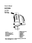
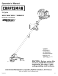
Operator's
Manual
2-Cycle
WEEDWACKER
®TRIMMER
Model No. 316.791020
INCREDI.PULL
TM
UNBELIEVABLE
STARTING
EA
SE
• SAFETY
ASSEMBLY
OPERATION
MAINTENANCE
PARTS LIST
ESPANOL, R 11
CAUTION: Before using this
product, read this manual and
understand all safety rules and
operating instructions.
Sears Brand Management
Corporation,
Visit our website:
769-06232
POO
Hoffman
Estates,
IL 60179, U.S.A.
www.craftsman.com
6/10
TABLE OF CONTENTS
Safety Rules ..................................................................................................
Warranty ........................................................................................................
Know Your Unit .............................................................................................
2
4
4
Assembly Instructions ...................................................................................
Oil and Fuel Information ................................................................................
4
5
Starting/Stopping
Instructions ......................................................................
5
Operating Instructions ..................................................................................
6
Maintenance and Repair Instructions ...........................................................
7
Cleaning and Storage ...................................................................................
8
Troubleshooting Chart ...................................................................................
9
Specifications .............................................................................................
10
Parts List .....................................................................................................
30
Service Numbers ..........................................................................
Back Cover
CALiFORNiA
PROPOSiTiON
he purpose of safety symbols is to attract your attention to possible dangers. I
he safety symbols, and their explanations, deserve your careful attention I
nd understanding. The safety warnings do not by themselves eliminate any I
anger. The instructions or warnings they give are not substitutes for proper_
ccident prevention measures.
|
SYMBOL
SAFETYis ALERT:
danger,
warning
or caution.
Attention
required in Indicates
order to avoid
serious
personal
injury.
May be used in conjunction with other symbols or pictographs.
NOTE:
THE ENGINE EXHAUST FROM THiS PRODUCT CONTAINS CHEMICALS
KNOWN TO THE STATE OF CAMFORNIA TO CAUSE CANCER, BIRTH
DEFECTS OR OTHER REPRODUCTIVE HARM
All information, illustrations, and specifications in this manual are based on the
latest product information available at the time of printing. We reserve the right
to make changes at any time without notice.
NOTE:
This Unit Can Use an Electric Start or Power Start Bit TM Optional
Accessory!
Please refer to the Electric Starter or Power Start Bit TM operator's manual for
proper use of these features. (Items Sold Separately! Please refer to page 8
of this manual for more information about purchasing these accessories.)
Read the Operator's Manual and follow all warnings and safety instructions.
Failure to do so can result in serious injury to the operator and/or bystanders.
•
Carefully inspect the area before starting the unit. Remove all debris such
as rocks, broken glass, nails, wire, string and other objects which may be
thrown or become entangled in the unit.
•
Squeeze the throttle control and check that it returns automatically to the
idle position. Make all adjustments or repairs before using the unit.
•
Always stop the unit when operation
one location to another.
•
Always hold the unit with both hands when operating. Keep a firm grip
on both handles or grips.
•
Do not force the unit. It will do the job better and with less likelihood of
injury at a rate for which it was designed.
Do not overreach or use from unstable surfaces such as ladders, trees,
steep slopes, rooftops, etc. Always keep proper footing and balance.
Do not operate the unit faster than the speed needed to do the job. Do
not run the unit at high speed when not in use.
If the unit strikes or becomes entangled with a foreign object, stop the
unit immediately and check for damage. Do not operate before repairing
damage. Do not operate the unit with loose or damaged parts.
n order keep
to ensure
safety of for
the later
operator
Please
these the
instructions
use. and any bystanders.
GENERAL SAFETY
Read the instructions
use of the unit.
Failure
obey afollow
safetythe
warning
result in injur_
others. toAlways
safety can
precautions
to
reduce the risk of fire, electric shock and personal injury.
SAFETY INSTRUCTIONS
BEFORE OPERATING
WARNING:
using the
unit, all safety
must be
followed.
PleaseWhen
read these
instructions
beforerules
operating
the unit
•
WARNING:
to yourself and
CAUTION:
Failure
to obey injury
a safety
warning or
may
property damage
or personal
to yourself
to result
others.in
Always follow the safety precautions to reduce the risk of fire,
electric shock and personal injury.
SPARK ARRESTOR NOTE
• IMPORTANT
vital to the operation or
Failure
to obey
safety warning
will result
in
to yourself
or toaothers.
Always follow
the safety
precautions to reduce the risk of fire, electric shock and personal
injury.
,_
READ ALL INSTRUCTIONS
Advises of information or instructions
maintenance of the equipment.
DANGER:
serious injury
65 WARNING
NOTE: For users on U.S. Forest Land and in the states of California, Maine,
Oregon and Washington.
All U.S. Forest Land and the state of California
(Public Resources Codes 4442 and 4443), Oregon and Washington require, by
law that certain internal combustion engines operated on forest brush and/or
grass-covered areas be equipped with a spark arrestor, maintained in effective
working order, or the engine be constructed, equipped and maintained for the
prevention of fire. Check with your state or local authorities for regulations
pertaining to these requirements. Failure to follow these requirements could
subject you to liability or a fine. This unit is factory equipped with a spark
arrestor. If it requires replacement, ask your LOCAL SERVICE DEALER to
install the Accessory Part #753=06418 Muffler Assembly
MEANING
carefully. Be familiar with the controls and proper
Keep these instructions. Refer to them often and use them to instruct
other users. If loaning this unit to others, also loan them these
instructions.
•
Do not operate this unit when tired, ill or under the influence of alcohol,
drugs or medication.
•
Children and teens under the age of 15 must not use the unit, except
teens guided by an adult.
•
•
Use the right tool. Only use this tool for its intended
purpose.
•
Use the unit only in daylight or good artificial light.
Wear safety glasses or goggles that meet ANSI Z87.1 standards and are
marked as such. Wear ear/hearing protection when operating this unit.
Wear a face or dust mask if the operation is dusty.
•
Wear heavy long pants, boots, gloves and a long sleeve shirt. Do not
wear loose clothing, jewelry, short pants, sandals or go barefoot. Secure
hair above shoulder level.
•
Inspect the unit before use. Replace damaged parts. Make sure all
fasteners are in place and secure. Replace parts that are cracked,
chipped or damaged in any way. Do not operate the unit with loose or
damaged parts.
•
All guards and safety attachments
operating the unit.
must be installed properly before
•
Use only replacement parts or accessories recommended for this
unit that are distributed by Sears or a Craftsman outlet. Use of any
replacement parts or accessories purchased elsewhere may be
hazardous, and will void the warranty.
o
•
Be aware of risk of injury to the head, hands and feet.
Clear the area of children, bystanders and pets; keep them outside a
50-foot (15 m) radius, at a minimum. Even then, they are still at risk
from thrown objects. Encourage bystanders to wear eye protection. If
approached, stop the unit immediately.
is delayed or when walking from
•
Keep unit clean of vegetation and other materials that may clog, gum
or bind moving parts, which may cause serious personal injury and or
damage to the unit.
•
Keep hands, face, and feet away from all moving parts. Do not touch or
try to stop any moving parts while they are in motion.
•
Allow the unit to cool before storing or transporting.
the unit while transporting.
Be sure to secure
•
Never douse or squirt the unit with water or any other liquid. Keep
handles dry, clean and free from debris. Clean after each use, see
Cleaning and Storage instructions.
•
Store the unit in a dry place, secured or at a height to prevent
unauthorized use or damage. Keep out of the reach of children.
OIL AND FUEL SAFETY
_
WARNING:
explode if ignited.
Gasoline
Take
•
Store fuel only in containers specifically
storage of such materials.
the
is highly
following
flammable
precautions:
and its vapors can
designed and approved for the
•
Always stop the engine and allow it to cool before filling the fue! tank.
Never remove the fue! tank cap or add fue! when the engine is hot. Never
operate the unit without the fue! cap securely in place.
•
Always mix or add fue! in a clean, well-ventilated
there are no sparks or flames. Do not smoke.
outdoor
Nevern Operate the unit without the fue! cap securely in place.
•
Avoid creating a source of ignition for spilled fue!. Wipe up any spilled
fuel from the unit immediately before startnqg the unblt. Move the unit at
least 30 fett (9.1 m) from the fuehng source and site before starting the
unit. Do not smoke.
•
•
•
Never start or run the unit inside a closed room or bulldnqg. Breathing
exhaust fumes can be fatal. Operate this unit only in a well-venhlated
outdoor area.
•
Check the unit for fuel leaks.
•
•
Loosen the fuel tank cap slowly to relieve any pressure in the tank.
Never store the unit with fuel in the tank, Hqslde a bulldHqg where fumes
may reach an open flame (pilot hghts, etc.) or sparks (switches, electrical
motors, etc.).
•
To reduce fire hazard, replace a faulty muffler and spark arrestor. Keep
the engine and muffler free from grass, leaves, excesswe grease or
carbon build up.
Avoid accidental startnqg. Be Hqthe starhng poslhon whenever pulhng
the starter rope. The operator and unit must be in a stable poslhon while
starting. Refer to Starting/Stopping
Instructions.
• SAFETY
Turn the engine to off and disconnect
repair.
TRIMMER SAFETY
MEANING
• SAFETY
Indicates ALERT
danger, SYMBOL
warnung or cauhon. May be used an
conjuncbon wuth other symbols or p_ctographs.
the spark plug for maintenance
or
•
The trimmer attachment shield must always be in place while operahng
the Emit. Do not operate unit without both trimming hnes extended, and
the proper hne _nstalled. Do not extend the tnmm_ng hne beyond the
length of the shield.
•
Adjust the D-handle that prowdes the best possible gnp.
•
Be sure the trimmer attachment
startnqg the unit.
•
Use only 0.095 H_.(2.41 mm) diameter replacement hne. Never use metalrenqforced hne, wire, chain or rope. These can break off and become
dangerous projechles.
Keep unit clean of vegetahon and other materials. They may become
lodged between the trimmer attachment and shield.
Keep hands, face, and feet away from all mowng parts. Do not touch or
try to stop the trimmer attachment when _trotates.
•
•
is not in contact with anything before
SAVE THESE
& INTERNATIONAL
This operator's manual describes safety and H_ternahonal symbols and plctographs
safety, assembly, operahng and manqtenance and repair informahon.
SYMBOL
Do not touch the engine, gear housing or muffler. These parts get
extremely hot from operahon, even after the unit is turned off.
This unit has a clutch. The unit attachment remaHqs stationary when the
engine is idhng. If _t does not, take the unit to a Sears or other quahfled
service dealer for an adjustment.
area where
•
•
•
INSTRUCTIONS
SYMBOLS
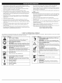
that may appear on this product.
Read the operator's
manual for complete
SYMBOL
MEANING
_7_o,_
/ _
• THROWN OBJECTS AND ROTATING CUTTER CAN
CAUSE SEVERE iNJURY
_-_'_-_J_
WARNING:
Small objects can be propelled
at hgh
speed, causing injury. Keep away from the rotating rotor.
Read the
operator's manual(s) and fellow
'_ WARNING:
READ OPERATOR'S
MANUAL
all warnings and safety instrucbone. Failure to do so can
result unserious injury to the operator and/or bystanders.
O
®
m
_,
• WEAR EYE AND HEARING
PROTECTION
WARNING:
Thrown objects and loud noise can cause
severe eye unjury and heanng loss. Wear eye protecbon
meeting ANSI Z87.1-1989 standards and ear protecben when
operabng th_s unit. Use a full face shield when needed
',UNLEADED
" WARNING:
KEEP BYSTANDERS
Keep allAWAY
bystanders, espec_aly cMdren
and pets, at Heast 50 feet (15 m.) from the operat,ng area.
FUEL
WARNING: Do not touch any metal eng=ne
, components.
HOT SURFACE
The engine gets extremely hot from
operation and may cause severe burns. Allow the unit to
completely cool pnor to any ma,ntence or serwc,ng.
,_ OiL
Refer to operator's
_i_
manual for the proper type of o_H.
Always use clean, fresh unleaded fuel
• PRIMER BULB
WARNING: it has been proven that fuel contain,rig
• DO NOT USE E85 FUEL iN THIS UNiT
greater than 10% ethanol w_lHhkely damage th,s eng,ne
and void the warranty.
(_
Push pnmer bulb, fully and slowly, t0 bmes.
SHARP BLADE
WARNING:
I
= ON/OFF CONTROL
ON / START / RUN
_ ON/OFF CONTROL
OFF or STOP
Sharp blade on trimmer attachment
shield. To prevent serious injury, do not touch the line
cutbng blade.
CRAFTSMAN
2 YEAR
FULL
WARRANTY
FOR 2 YEAR(S) from the date of purchase, this product is warranted against any defects in material or workmanship.
or free replacement if repair is unavailable.
For warranty coverage details to obtain repair or replacement, visit the web site: www.craftsman.com
This warranty
covers ONLY defects
in material
and workmanship.
Warranty
coverage
Defective product will receive free repair
does NOT include:
•
Expendable
items that can wear out from normal use within the warranty period, such as line, filters, or spark plugs.
•
•
Product damage resulting from user attempts at product modification or repair or caused by product accessories.
Repairs necessary because of accident or failure to operate or maintain the product according to all supplied instructions.
•
Preventive maintenance, or repairs necessary due to improper fuel mixture, contaminated or stale fuel.
This warranty is void if this product is ever used while providing commercial services or if rented to another person. This warranty gives you specific legal
rights, and you may also have other rights which vary from state to state.
Sears Brands Management
Corporation,
Hoffman Estates, IL 60179
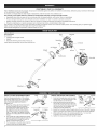
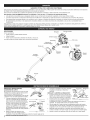
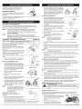
APPLiCATiONS
AS a trimmer:
Muffler
*
Cutting grass and light weeds.
.
.
Edging
Decorative trimming
around trees, fences, etc.
Other optional accessories
Starter
Sparl : Plug
Rope
may be used with this unit.
On/Off
Switch
Choke
D-Handle
Throttle
Convertible
Coupler
Lever
Fuel Cap
Control
TM
Shield
Cutting
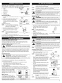
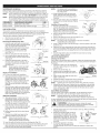
INSTALL CUTTING ATTACHMENT
SHIELD
Shield
Use the following instructions if the cutting
attachment shield on the unit is not installed.
Use only the instructions that apply to the
type of shaft and shield that the unit is
equipped with.
"_
1.
2.
3.
Place the
the shaft
mounting
the edge
cutting attachment shield onto
housing. Be sure the guard
bracket slides into the slot on
of the cutting shield. Rotate
(Fig. 1). The holes in the guard mounting
bracket and cutting attachment shield will
line up.
the shield into place, counterclockwise
___I
From inside the cutting attachment shield,
push the square bolt through the hole until
the threaded end protrudes through the
guard mounting bracket (Fig. 2).
Put the washer on the bolt, then screw the
wing nut onto the bolt and tighten.
\
Mount
[' jDra_Ket
_--'
iNSTALL AND ADJUST
1.
2.
the handle and push through. Place the
washer on the bolt, then screw the wing
nut onto the bolt. Do not tighten until
making the handle adjustment.
Fig. 1
square Bolt
I
I Washer
wing Nut
Fig.2
THE D-HANDLE
Push the D-handle down onto the shaft
housing (Fig. 3). The hex bolt hole in the
handle should be on the left side.
Insert the the bolt into the hex hole in
D-Handle
Grip
IJWing
Nut
Min. 6 in.
(15.24 cm)
"Bolt
Fig. 3
3.
Rotate the D-handle to place the grip above the top of the shaft housing.
Place it a minimum of 6 inches (15.24 cm) from the end of the shaft grip.
4.
While holding the unit in the operating position (Fig. 11), move the
D-handle to the location that provides the best grip.
5.
Tighten the wing nut until the D-handle is secure.
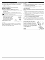
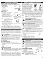
OPERATING THE CONVERTIBLE
TM
COUPLER
SYSTEM
The Convertible TM coupler system enables the use of these optional add-ons.
For information about attachments, call 1-800-4-MY-HOME®.
Rapid Link
Cou
Edger
Cultivator
Turbo Blower
Release
Button
TM
IF...
the unit came with a bottle of 2-cycle oil; pour the entire bottle into
1 gallon of gas and mix thoroughly.
NOTE:
One gallon (3.8 liters) of unleaded fuel mixed with one 3.2 oz. (95
ml.) bottle of 2-cycle oil makes a 40:1 fuel/oil ratio.
NOTE:
Dispose of the old fuel/oil mix in accordance
Local regulations.
to Federal, State and
Brushcutter
may explode. Always stop the engine and allow it to cool before
filling the fuel tank.
Do notis smoke
while
filling the Ignited
tank. Keep
WARNING:
Gasoline
extremely
flammable.
vapors
sparks and open flames at a distance from the area.
Pole Saw
Hedge Trimmer
Guide Recesss
Removing the Add-On
1. Turn the knob counterclockwise
(Fig. 6).
FUELING THE UNIT
Fig. 4
to loosen
_
Primary
Hole
2.
WARNING:
Remove
slowly
avoid
frominfuel
spray. Never operate
the fuel
unit cap
without
thetofuel
cap injury
securely
place.
\
Press and hold the release button (Fig. 4). _
\
While firmly holding the upper shaft
.._.q__\__ ______________\
housing, pull the lower shaft housing
straight out of the Convertible TM coupler
(Fig. 5).
Upper Shaft
Lower Shaft
Housing
Installing the Add=On
Housing
3.
NOTE:
1.
2.
To make installing or removing the
add-on easier, place the unit on the
ground or on a work bench.
Turn knob counterclockwise to loosen (Fig. 6).
While firmly holding the add-on, push it
straight into the Convertible TM coupler
(Fig. 5).
NOTE:
_,
Turn unit on its side, with the fuel cap facing up, and remove the fuel cap.
Place the gas container's spout into the
fill hole on the fuel tank and fill the tank.
(Fig. 7)
NOTE:
Do not overfill the tank.
1.
2.
Hole
Knob
Fig. 6
3.
Wipe up any gasoline that may have
spilled.
4.
5.
Reinstall the fuel cap.
Move the unit at least 30 ft. (9.1 m) from
the fueling source and site before starting
the engine.
3. Turn the knob clockwise to tighten (Fig. 6).
For decorative trimming/edging
with the line cutting head, lock the release
button into the 90 ° hole (Fig. 6).
OiL AND FUEL MIXING INSTRUCTIONS
_1_
Old and/or improperly mixed fuel are the main reasons for the unit not
running properly. Be sure to use fresh, clean unleaded fuel. Follow the
instructions carefully for the proper fuel/oil mixture.
Definition of Blended Fuels
: It has
proven
fuel containing
greater
than II
will
likelybeen
damage
thisthat
engine
and void the
warranty.
I
Fuels
WARNING:
reliability, pay
For proper
andmixing
maximum
strict
attentionengine
to theoperation
oil and fuel
instructions on the 2-cycle oil container. Using improperly mixed
fuel can severely damage the engine.
If choosing to use a blended fuel, or its use is unavoidable,
recommended precautions:
NOTE:
This unit has the Incredi-Pull TM starting system, which significantly
reduces the effort required to pull the starter rope.
STARTING INSTRUCTIONS
1.
manual
Drain the tank and run the engine dry before storing the unit
It is recommended to use the manufacturers 2-cycle oil with this unit. If
unavailable, use a good 2-cycle oil designed for air-cooled engines along
with a fuel additive, such as STA-BIL® Gas Stabilizer or an equivalent.
Add 0.8 oz. (23 ml.) of fuel additive
per gallon of fuel according to the
instructions on the container. NEVER
add fuel additives directly to the unit's
fuel tank.
Mixing The Fuel
UNLEADED
1 GALLON
GAS
US
(3.8 LITERS}
1 LITER
MiXiNG
2 CYCLE
elL
3,2 FL OZ,
(95 ML)
25 ML
RATIO - 40:1
Mix fuel with oil. See Oil and Fuel Mixing Instructions.
On/Off
2.
Fill the fuel tank with fresh, clean fuel mix.
Refer to Fueling the Unit.
NOTE:
There is no need to turn the unit on.
The On/Off Control is in the ON ( I )
position at all times (Fig. 8).
3.
Fully press and release the primer bulb 10
times, slowly. Some amount of fuel should
be visible in the primer bulb and fuel lines
(Fig. 9). If fuel can not be seen in the bulb,
press and release the bulb until fuel is
visible.
4.
Flip the choke lever clockwise
(Fig. 9).
5.
Crouch in the starting position (Fig. 10). Do
not squeeze the throttle. Pull the starter
rope in a controlled motion until the unit
starts.
Wait and allow the unit to idle for 5 - 10
seconds. If the unit stops running during
this time, squeeze the throttle control and
pull the starter rope in a controlled motion
until the unit starts.
Using Fuel Additives
Thoroughly mix the proper ratio of
2-cycle engine oil with unleaded fuel
in a separate fuel can. Use a 40:1 fuel/
oil ratio. Do not mix them directly in
the engine fuel tank. See the table for
specific gas and oil mixing ratios
monoxide
Operate this
exhaust
unit fumes
only in can
a well-ventilated
be lethal in a outdoor
confined area.
Make(Fig.
sure10).
to be
in the
rope
To avoid
serious injury, the operator and unit must be in a stable position
while starting.
follow
Always use the fresh fuel mix explained in the operator's
Always agitate the fuel mix before fueling the unit
WARNING:
area. Carbon
WARNING:
starting position Avoid
when accidental
pulling the starting.
starter
Today's fuels are often a blend of gasoline and oxygenates such as ethanol,
methanol, or MTBE (ether). Alcohol-blended
fuel absorbs water. As little as
1% water in the fuel can make fuel and oil separate. It forms acids when
stored. When using alcohol-blended
fuel, use fresh fuel (less than 30 days
old).
Using Blended
Add up
fuelany
in aspilled
clean, fuel
levelimmediately.
and well ventilated
Wipe
Avoid
creating a source of ignition for spilled fuel. Do not start the
engine until fuel vapors dissipate.
Fig. 5
goo Edging
Aligning the release button with the
guide recess will help installation
(Fig. 4).
WARNING
10% ethanol
WARNING:
outdoor area.
6.
7.
control
Throttle
control
J
Fig, 8
until it clicks
Fig. 9
Starting
Squeeze and hold the throttle control for 30
Position
to 60 seconds to allow the unit to warm up.
IF,..
The engine does not start, go back
to step 3.
Fig, 10
NOTE:
If the unit is hot and fails to start
within 3 pulls of the starter rope, squeeze the throttle control and
pull the starter rope until the unit starts.
STOPPING INSTRUCTIONS
HOLDING
1.
Release the throttle control and allow the engine to cool down by idling.
2.
Press and hold the On/Off Control switch in the OFF (O) position until the
unit comes to a complete stop (Fig. 8).
Before operating the unit, stand in the operating position (Fig. 11). Check for
the following:
NOTE:
This Unit Can Use an Power Start or Power Start Bit Optional
Accessory!
Please refer to the Power Starter or Power Start Bit operator's
manual for proper use of these features. (Items may be Sold
Separately! Please refer to page 8 of this manual for more
information about purchasing these accessories.)
STARTING INSTRUCTIONS
1.
Mix fuel with oil. See Oil and Fuel Mixing Instructions.
2. Fill the fuel tank with fresh, clean fuel mix. Refer to Fueling the Unit.
NOTE:
There is no need to turn the unit on. The On/Off Control is in the
ON ( I ) position at all times (Fig. 8).
3.
4.
Fully press and release the primer bulb 10 times, slowly. Some amount of
fuel should be visible in the primer bulb (Fig. 9). If fuel cannot be seen in
the bulb, press and release the bulb until fuel is visible.
Flip the choke lever clockwise until it clicks (Fig. 7).
5.
Crouch in the starting position (Fig. 8). Do not squeeze the throttle. Place
the Plug-In Power Start or Power Bit Start into the back of the unit. Refer
to the Operation section of the Plug-In Power Start or Power Bit Start
operator's manual.
6.
Press and hold the ON (I) button of the Plug-in Power Start or Power Bit
Start equipped drill in intervals no longer than 4 seconds each until the
unit starts.
7.
Wait and allow the unit to idle for 5 - 10 seconds. If the unit stops running
during this time, squeeze the throttle control, then press and hold the ON
(I) button of the Plug-in Power Start or Power Bit Start equipped drill in
intervals no longer than 4 seconds each until the unit starts.
8.
9.
THE UNiT
•
The operator is wearing eye protection
and proper clothing
•
With a slightly-bent right arm, the
operator's hand is holding the shaft grip
•
The operator's left arm is straight, the left
hand holding the D-handle
The unit is at waist level
•
•
Fig. 11
The cutting head is parallel to the ground
and easily contacts the grass without the need to bend over
ADJUSTING
TRIMMING
LINE LENGTH
The Bump Head TM cutting head allows the release of trimming line without
stopping the engine. To release more line, lightly tap the cutting head on the
ground (Fig. 12) while operating the unit at high speed.
NOTE:
Always keep the trimming line fully
extended. Line release becomes
more difficult when the cutting line
gets shorter.
Each time the head is bumped, about 1 inch
(25.4 mm) of trimming line releases. A blade in
the cutting head shield will cut the line to the
proper length if any excess line is released.
Fig. 12
For best results, tap the bump knob on
bare ground or hard soil. If attempting a line
release in tall grass, the engine may stall. Always keep the trimming line fully
extended. Line release becomes more difficult when the cutting line gets
shorter.
NOTE:
Do not rest the Bump Head
running.
TM
on the ground while the unit is
Some line breakage will occur from:
•
•
Entanglement with foreign matter
Normal line fatigue
•
•
Attempting to cut thick, stalky weeds
Forcing the line into objects such as walls or fence posts
Remove the Plug-In Power Start or drill from the unit.
Squeeze and hold the throttle control for 30 to 60 seconds to allow the
unit to warm up.
IF...
The engine does not start, go back to step 3.
TIPS FOR BEST TRIMMING
IF...
•
Keep the cutting head parallel to the ground.
•
Do not force the cutting head. Allow the tip of the line to do the cutting,
especially along walls. Cutting with more than the tip will reduce cutting
efficiency and may overload the engine.
Cut grass over 8 inches (200 mm) by working from top to bottom in small
increments to avoid premature line wear or engine drag.
Cut from right to left whenever possible. Cutting to the left improves the
unit's cutting efficiency. Clippings are thrown away from the operator.
Slowly move the unit into and out of the cutting area at the desired
height. Move either in a forward-backward
or side-to-side motion.
Cutting shorter lengths produces the best results.
The engine fails to start after a few attempts, squeeze the throttle
control, then press and hold the Plug-In Power Start or drill ON
(I) button in intervals no longer than 4 seconds each until the unit
starts.
STOPPING INSTRUCTIONS
1.
Release the throttle control and allow the engine to cool down by idling.
2.
Press and hold the On/Off Control switch in the OFF (O) position until the
unit comes to a complete stop (Fig. 8).
•
•
•
RESULTS
•
Trim only when grass and weeds are dry.
•
•
The life of the cutting line is dependent
Following the trimming techniques
•
•
What vegetation is being cut
Where vegetation is cut
upon:
For example, the line will wear faster when trimming
wall as opposed to trimming around a tree.
DECORATIVE TRiMMiNG
against a foundation
Decorative trimming is accomplished by
removing all vegetation around trees, posts,
fences, etc..
Rotate the whole unit so that the cutting head
is at a 30 ° angle to the ground (Fig. 13).
Fig. 13
MAINTENANCE
SCHEDULE
NOTE:
Perform these required maintenance procedures at the frequency stated in
the table. These procedures should also be a part of any seasonal tune-up.
NOTE:
NOTE:
Some maintenance procedures may require special tools or skills. For
these types of repairs call 1-800-4-MY-HOME®
for more information.
Please read the California/EPA statement that came with the unit
for a complete listing of terms and coverage for the emissions
control devices, such as the spark arrestor, muffler, carburetor, etc
FREQUENCY
MAINTENANCE
REQUIRED
SEE
Every 10 hours
Clean and re-oil air filter
p. 7
Every 25 hours
Check spark plug condition and gap
p. 8
LiNE INSTALLATION
This section covers both SplitLine® and standard single line installation.
Always use original equipment manufacturer 0.095 in. (2.41 mm) replacement
line. Line other than the specified may make the engine overheat or fail.
There are two methods to replace the trimming line:
Wind the inner reel with new line
Knob
Install a prewound
inner reel
Bolt
Removing the Existing inner Reel
1. Hold the outer spool with one hand and
unscrew the bump knob counterclockwise
(Fig. 14). Inspect the bolt inside the
bump knob to make sure it moves freely.
Replace the bump knob if damaged.
2.
Remove the inner reel from the outer
spool (Fig. 15).
3.
4.
Remove spring from the inner reel (Fig. 15).
Use a clean cloth to clean the the inner
reel, spring, shaft, and inner surface of the
outer spool.
5.
Check the indexing teeth on the inner
reel and outer spool for wear (Fig. 16). If
necessary, remove burrs or replace the
reel and spool,
NOTE:
Always use the correct line length
when installing trimming line on
the unit. The line may not release
properly if the line is too long.
Single Line Installation
Go To Step 8 for SplitLine®
The spring must be assembled on
the inner reel before reassembling
the cutting head.
14. While holding the inner reel and outer
spool, grasp the ends and pull firmly to
release the line from the holding slots in
the spool.
15. Hold the inner reel in place and install the
bump knob by turning clockwise. Tighten
securely.
Installing a Prewound Reel
1. Hold the outer spool with one hand and
unscrew the bump knob counterclockwise
(Fig. 14). Inspect the bolt inside the
bump knob to make sure it moves freely.
Replace the bump knob if damaged.
2. Remove the old inner reel from the outer
spool (Fig. 15).
3.
4.
5.
Take approximately
20 feet (6 m) of new
7.
lengths. Insert each end of the line
through one of the two holes in the inner
reel (Fig. 17). Pull the line through the
inner reel so that the loop is as small as
trimming
possible. line, loop it into two equal
Wind the lines in tight even layers onto the
reel (Fig. 18). Wind the line in the direction
indicated on the inner reel. Place an index
finger between the two lines to stop the
lines from overlapping. Do not overlap the
ends of the line. Proceed to step 12.
SplitLine® InstaUation
8. Take approximately 10 feet (3 m) of new
trimming line. Insert one end of the line
through one of the two holes in the inner
reel (Fig. 19). Pull the line through the inner
reel until only about 4 inches is left out.
9. Insert the end of the line into the open
hole in the inner reel and pull the line tight
to make the loop as small as possible
(Fig. 19).
20
Fig.
21
The spring must be assembled on the inner reel before
reassembling the cutting head.
Insert or slide the ends of the line through or into the eyelets in the outer
spool (Fig. 21).
6.
Fig.14
Outer
-_
Spool
\
--_
Place the new inner reel inside the outer spool. Push the inner reel and
outer spool together. While holding the inner reel and outer spool, grasp
the ends and pull firmly to release the line from the holding slots in the
spool.
7. Hold the inner reel in place and install the bump knob by turning
clockwise. Tighten securely.
AiR FILTER MAINTENANCE
Cleaning the Air Filter
The air filter is an important item to maintain. Failure to maintain the air filter
properly can result in poor performance or can cause permanent damage to
the engine.
\\
Fig.15
index Teeth
Fig.16
1.
Open the air filter cover by pressing the
lock tab in and pulling out on the air filter
cover (Fig. 22).
2.
3.
Remove the air filter (Fig. 22).
Wash the filter in detergent and water.
Rinse the filter thoroughly and allow it to
dry.
4.
Apply enough clean SAE 30 motor oil to
lightly coat the filter.
5.
. J..dJ/Loop
LockTab
AirFilterCover
Air Filter
Fig. 22
Squeeze the filter to spread and remove excess oil.
6. Replace the air filter into the base plate (Fig. 22).
NOTE:
Operating the unit without the air filter WILL VOID the warranty.
7. Reinstall the air filter cover. Position the two small tabs on the air filter
cover into the two slots in the base plate and press the air filter cover
down, making sure to align the lock tab with the lock tab slot, until it
snaps into place (Fig. 22).
IDLE SPEED ADJUSTMENT
Fig.17
The idle speed of the engine is adjustable. An idle adjustment screw is
between the air filter cover and the engine starter housing (Fig. 23).
NOTE:
Careless adjustments can seriously damage the unit. An
authorized service dealer should make carburetor adjustments.
If, after checking the fuel mixture and cleaning the air filter, the engine still will
not idle, adjust the idle speed screw as follows:
\
Fig.18
WARNING,
Cutting
head may
spin and
during
idle speed
adjustments. Wear
protective
clothing
observe
all safety
instructions to prevent serious personal injury.
1.
10. Before winding, split the line back about
6 inches.
11. Wind the line in tight even layers in the
direction indicated on the inner reel.
NOTE:
Failure to wind the line in the
direction indicated will cause the
cutting head to operate incorrectly.
Fig.
Teeth
Remove the spring from the old inner reel (Fig. 15).
Place the spring in the new inner reel.
NOTE:
Installation:
6.
P,
\index
2.
Loop
Fig.19
12. Insert the ends of the line into the two holding slots (Fig. 20).
13. Insert or slide the ends of the line through or into the eyelets in the outer
spool and place inner reel with spring inside the outer spool (Fig. 21).
Push the inner reel and outer spool together.
3.
Start the engine and run for one minute to warm up. Refer to Starting/
Stopping Instructions.
Release the throttle trigger and let the
engine idle. If the engine stops, insert
a small phillips screwdriver into the idle
adjustment screw (Fig. 23). Turn the idle
speed screw clockwise 1/8 of a turn at
a time (as needed) until the engine idles
smoothly.
If the engine appears to be idling
Fig. 23
too fast, turn the idle speed screw
counterclockwise
1/8 of a turn at a time (as needed), to reduce idle
speed.
Checking
thefuelmixture,
cleaning
theairfilterandadjusting
theidlespeed
should
solve
most
engine
problems.
Ifnotandallofthefollowing
aretrue:
• theengine
willnotidle
• theengine
hesitates
orstalls
onacceleration
• there
isalossofengine
power
Have
thecarburetor
adjusted
byanauthorized
service
dealer.
STORAGE
REPLACING
LONG TERM STORAGE
THE SPARK PLUG
•
Never store a fueled unit where fumes may reach an open flame or spark.
•
•
Allow the engine to cool before storing.
Store the unit locked up to prevent unauthorized
•
•
Store the unit in a dry, well-ventilated area.
Store the unit out of the reach of children.
use or damage.
Use replacement #753=06193, a Champion RDJ7J spark plug, or
equivalent. The correct air gap is 0.025 inch (0.635 mm).
If planning on storing the unit for an extended time, use the following storage
procedure:
1.
Stop the engine and allow it to cool. Grasp the plug wire firmly and pull it
from the spark plug.
1.
2.
Clean around the spark plug. Remove the spark plug from the cylinder
head by turning a 5/8-inch socket counterclockwise.
2.
WARNING:
Do not
sand blast,
scrape or clean electrodes. Grit
in the engine could
damage
the cylinder.
3.
4.
Replace a cracked, fouled or dirty spark
plug. Set the air gap at 0.025 in. (0.635
mm) using a feeler gauge (Fig. 24).
Install a correctly-gapped
spark plug in
the cylinder head. Tighten by turning the
5/8-inch socket clockwise until snug.
If using a torque wrench, torque to:
110=120 in.-Ib. (12.3=13.5 Nora)
3.
Drain all fuel from the fuel tank into a container with the same 2-cycle
fuel mixture. Do not use fuel that has been stored for more than 30 days.
Dispose of the old fuel/oil mix in accordance to Federal, State and Local
regulations.
Start the engine and allow it to run until it stalls. This ensures that all fuel
has been drained from the carburetor.
Allow the engine to cool. Remove the spark plug and put 3 - 5 drops of
any high quality motor oil or 2-cycle oil into the cylinder. Pull the starter
rope slowly to distribute the oil. Reinstall the spark plug.
NOTE:
4.
Remove the spark plug and drain all of the oil from the cylinder
before attempting to start the unit after storage.
Thoroughly clean the unit and inspect it for any loose or damaged parts.
Repair or replace damaged parts and tighten loose screws, nuts or bolts.
The unit is ready for storage.
Fig. 24
Do not over tighten.
START FEATURES
CLEANING
This unit can be started with an optional Plug-in
Power Start or Power Bit Start, (items may be sold
PLUG=iN
START
ANDthePOWER
separately).POWER
If choosing
to start
unit usingBiT
one of _I[_H
these features or have questions, please contact your
Use a small brush to clean off the outside of the unit. Do not use strong
detergents. Household cleaners that contain aromatic oils such as pine
and lemon, and solvents such as kerosene, can damage plastic housing or
handle. Wipe off any moisture with a soft cloth.
for more information and purchasing. You may also
go
local
to Craftsman
www.craftsman.com.
retailer or call 1-800-4-MY-HOME®
_
_C%Ij_
_
Electric
iTEM NO.
a _
Start
Feature
DESCRiPTiON
316.85951 ........................................................................
Plug-In Power Start
316.85952 ...............................................................................
Power Bit Start
PROBLEM
SOLUTION
Primer bulb wasn't pressed enough
Slowly press primer bulb 10 times
Fouled spark plug
Replace or clean the spark plug
Improper idle speed
Adjust according to the Idle Speed Adjustments
Fouled spark plug
Replace or clean the spark plug
Cutting head out of line
Refill with new line
Cutting head dirty
Clean inner reel and outer spool
Line twisted when refilled
Disassemble and rewind the line
Oil, cleaner or lubricant in cutting head
Clean and thoroughly
dry the cutting head
section.
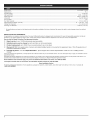
Engine
Type
..................................................................................................................................................................
Air-Cooled,
2-Cycle
Displacement
.................................................................................................................................................................
25cc
Operating
RPM
..............................................................................................................................................................
6,500
rpm
IdleSpeed
RPM
..............................................................................................................................................................
3,200
- 4,400
rpm
Spark
Plug
Gap
..............................................................................................................................................................
0.025
in.(0.635
mm)
Lubrication
...................................................................................................................................................................
Fuel
Oil/Mixture
Fuel/Oil
Ratio
................................................................................................................................................................
40:1
Fuel
Tank
Capacity
...........................................................................................................................................................
10fl.oz.(296
ml)
Approximate
UnitWeight
(Nofuel)
...........................................................................................................................................
10-11Ibs.(4.5-5kg)
Cutting
PathDiameter
.......................................................................................................................................................
16in.(40.64
cm)
Trimming
LineDiameter
......................................................................................................................................................
0.095
in.(2.41
mm)
* Allspecifications
arebased
onthelatest
product
information
available
atthetimeofprinting.
Wereserve
theright
tomake
changes
atanytimewithout
notice.
REPAIR PROTECTION
AGREEMENTS
Congratulations on making a smart purchase. Your new Craftsman@ product is designed and manufactured for years of dependable operation. But like all
products, it may require repair from time to time. That's when having a Repair Protection Agreement can save you money and aggravation.
Here is what the Repair Protection
58
Expert
service
by our 10,000
58
Unlimited
58
Product
58
Discount
preventive
of 10% from
maintenance
58
Fast help
manual."
by phone
service
and
replacement
Plan Agreement
professional
no charge
for parts
includes:
repair
specialists
and labor on all covered
up to $1 500 if your covered
regular price of service
checks
- we call it Rapid
product
and related
Resolution
- phone
repairs
can not be fixed
installed
parts
not covered
by the agreement;
support
from a Sears representative.
also,
10% off regular
Think of us as a "talking
price of
owner's
Once you purchase the Agreement, a simple phone call is all that it takes for you to schedule service. You can call anytime day or night, or schedule a service
appointment online.
The Repair Protection Agreement is a risk-free purchase. If you cancel for any reason during the product warranty period, we will provide a full refund. Or a
prorated refund anytime after the product warranty period expires. Purchase you Repair Protection Agreement today!
Some limitations and exclusions
*Coverage
For Sears professional
1=800=4=MY=HOME®.
10
apply. For prices and additional
in Canada varies on some items. For full details
installation of home appliances,
information
in the U.S.A. call 1=800=827=6655.
call Sears Canada at 1 =800=361 =6665.
Sears installation
Service
garage door openers, water heaters, and other major home items, in the U.S.A. or Canada call
Manual del Operador
RECORTADORA
® WEEDWACKER
de 2 Tiempos
Modelo No. 316.791020
INCREDI.PULL
TM
UNBELIEVABLE
STARTING
EA
SE
•
•
•
•
SEGURIDAD
ENSAMBLAJE
OPERACION
MANTENIMIENTO
LISTA DE PIEZAS
PRECAUCION: Antes de utilizar
este producto, lea este manual y
familiaricese
con todas las reglas
de seguridad e instrucciones de
operaci6n.
Sears Brand Management
Corporation,
Hoffman Estates, iL 60179, U.S.A.
Visite nuestro sitio web: www.craftsman.com
769-06232
POO
6/10
TABLADECONTENIDO
Reglas de seguridad .....................................................................................
Garantia ........................................................................................................
Conozca su unidad .......................................................................................
2
4
4
Instrucciones de ensamblaje ........................................................................
4
Informaci6n sobre aceite y combustible .......................................................
5
Instrucciones de arranque y apagado ..........................................................
5
Instrucciones de operaci6n ...........................................................................
6
Instrucciones de mantenimiento y reparaci6n ..............................................
7
Limpieza y almacenamiento .........................................................................
8
Tabla de Iocalizaci6n y soluci6n de problemas .............................................
9
Especificaciones .........................................................................................
10
Lista de piezas ............................................................................................
30
NQmeros de servicio ...............................................................
Contracubierta
ADVERTENCIA
SOBRE LA PROPOSIClON
CALIFORNIA
El prop6sito de los simbolos de seguridad es Ilamar su atenci6n sobre I
posibles peligros. Los simbolos de seguridad y sus explicaciones merecen
toda su atenci6n y comprensi6n. Las advertencias de seguridad no eliminan
por si mismas ningOn peligro. Las instrucciones o advertencias que dan no
sustituyen a las medidas adecuadas de prevenci6n de accidentes.
I
SJMBOLO
SIGNIFICADO
ALERTA
SEGURIDAD:
peligro,graves
advertencia
o precauci6n.DE
Debe
prestar atenci6n Indica
para evitar
lesiones
personales. Puede utilizarse junto a otros simbolos o pictografias.
NOTA:
Indica informaci6n o instrucciones de vital importancia
operaci6n o el mantenimiento del equipo.
para la
PELIGRO:
El no
como consecuencia
obedecer
advertencia
seguridad
traera
que usteduna
u otras
personasdesufran
graves
lesiones. Siga siempre las precauciones de seguridad para reducir
el riesgo de incendio, descarga el_ctrica o lesiones personales.
65 DEL ESTADO DE
ADVERTENCIA:
una advertencia
de
seguridad puede Ilevar El
a no
queobedecer
usted u otras
personas sufran
lesiones. Siga siempre las precauciones de seguridad para reducir
el riesgo de incendio, descarga electrica o lesiones personales.
CONGENITAS
PRECAUCK)N:
El no obedecer
advertencia
de usted u
seguridad puede provocar
daSos a launa
propiedad
o que
otras personas se lesionen. Siga siempre las precauciones de
seguridad para reducir el riesgo de incendio, descarga electrica
o lesiones personales.
U OTROS DANOS AL SJSTEMA REPRODUCTOR.
NOTA SOBRE EL PARACHISPAS
NOTA: Para usuarios de la Zona Forestal de EE. UU., y los estados de
California, Maine, Orog6n y Washington.
Todas las Zonas Forestales de
EE.UU, asi como los estados de California (C6digos de Recursos PQblicos
4442 y 4443), Oreg6n y Washington exigen, por ley, que determinados
motores de combusti6n interna operados en matorrales boscosos y/o zonas
cubiertas de hierba, est_n equipados con un parachispas y se mantengan
en buen estado de funcionamiento,
o que el motor sea construido, equipado
y mantenido con vista a la prevenci6n de incendios. Compruebe con sus
autoridades estatales o locales las regulaciones relacionadas con estos
requisitos. Si no cumple estos requisitos podria estar sujeto a responsabilidad
civil o multa. Esta unidad viene oquipada de f_brica con un parachispas.
Si necesita reemplazarlo, pidale a su DISTRIBUIDOR DE SERVlCIO LOCAL
instalarle la PJeza AccesorJo #753-06418 deJ conjunto deJ silencJador.
Toda la informaci6n, las ilustraciones y especificaciones
que contiene este
manual se basan en la informaci6n mas reciente del producto, existente en el
momento de la impresi6n. Nos reservamos el derecho de hacer cambios en
cualquier momento, sin previo aviso.
NOTA:
iEsta unidad puedo utJlizar un arrancador
el_ctrico oun
accosorio opcionaJ Power Bit StartTM!
Para utilizar correctamente estos dispositivos, consulte el manual
del operador del arrancador electrico o del accesorio Power Bit
Start TM. (iLos accesorios se venden pot separado! Para informarse
mas sobre la compra de estos accesorios, vaya a la pagina 8 de
este manual).
Lea el Manual del Operador y siga todas las advertencias e instrucciones de
seguridad. No hacerlo puede ocasionar lesiones graves al operador y/o alas
personas presentes.
• INSTRUCCIONES DE SEGURIDAD IMPORTANTES
LEA TODAS LAS INSTRUCCIONES ANTES DE OPERAR LA UNIDAD
• Utilice solamente las piezas o accesorios de repuesto recomendados
para esta unidad, distribuidos pot Sears ouna tienda Craftsman. Usar
cualquier otra pieza o accesorio de repuesto comprada en otra parte
puede ser peligroso y anulara su garantia.
SEGURJDAD GENERAL
ADVERTENCIA:
normas de seguridad.
AI
usar
la unidad
deben seguirse
las
Lea
estas
instrucciones
antes de todas
operarla
a fin de garantizar la seguridad del operador y de cualquier
otra persona presente. Guarde estas instrucciones para poder
usarlas m&s adelante.
Tenga en cuenta el riesgo de lesiones a la cabeza, las manos y los pies.
Aleje a los ni_os, personas presentes y animales domesticos del area;
mant_ngalos fuera de un radio de 50 pies (15 m) como minimo. AQn asi,
todavia corren el riesgo de set alcanzados pot los objetos que salen
despedidos. Sugiera a los presentes usar protecci6n para los ojos. Si
alguien se le acerca, apague la unidad de inmediato.
•
Inspeccione cuidadosamente
el area antes de encender la unidad. Retire
las piedras, vidrios rotos, clavos, alambres, cadenas y otros objetos que
podrian salir despedidos o enredarse en la unidad.
Apriete el control del regulador y compruebe que regrese
automaticamente a la posici6n de marcha en vacio. Haga todos los
ajustes o reparaciones antes de usar la unidad.
•
Lea detenidamente las instrucciones.
uso adecuado de la unidad.
•
Guarde estas instrucciones. ConsQItelas con frecuencia y utilicelas
para instruir a otros usuarios. Si le presta esta unidad a otras personas,
prestele tambien estas instrucciones.
•
No opere esta unidad siesta cansado,
alcohol, drogas o medicamentos.
•
Los ni_os y adolescentes menores de 15 arcs no deben usar la unidad.
Los adolescentes pueden hacerlo bajo la supervisi6n de un adulto.
•
•
Use la herramienta correcta. Use esta herramienta solamente para el
prop6sito previsto.
Use la unidad Qnicamente a la luz del dia o con buena luz artificial.
Apague siempre la unidad cuando la operaci6n
de un lugar a otro.
•
Sostenga siempre la unidad con ambas manos al operarla. Agarre
firmemente ambas manijas o empu_aduras.
•
No fuerce la unidad. El equipo funcionara mejor y con menos
probabilidad de accidentes a la velocidad para la que fue dise_ado.
No intente alcanzar demasiado lejos ni Io use parado en superficies
inestables como escaleras, arboles, pendientes pronunciadas, techos,
etc. Mantenga siempre la posici6n y el equilibrio adecuados.
•
•
Familiaricese
•
•
con los controles y el
enfermo o bajo los efectos del
Lleve puestas gafas o lentes de seguridad que cumplan con las normas
ANSI Z87.1 y est_n marcados como tales. Use siempre protecci6n para
los oidos al operar esta unidad. P6ngase una mascara facial o contra el
polvo si la operaci6n levanta polvo.
•
Use pantalones largos y gruesos, botas, guantes y camisa de mangas
largas. No use ropa holgada, alhajas, pantalones cortos, sandalias ni
ande descalzo. Asegure su cabello pot encima del nivel de los hombros.
•
Inspeccione la unidad antes de utilizarla.
AsegQrese de que todos los sujetadores
Reemplace las piezas rajadas, melladas
No opere la unidad si tiene piezas flojas
•
Todos los los accesorios de protecci6n y seguridad deben estar
correctamente instalados antes de comenzar a operar la unidad.
12
Reemplace las piezas da_adas.
esten en su sitio y asegurados.
o da_adas de cualquier forma.
o da_adas.
•
•
se demote o al caminar
•
No opere la unidad a una velocidad mayor que la necesaria para realizar
el trabajo. No ponga a funcionar la unidad a alta velocidad si no Io esta
usando.
•
Si la unidad golpea o se enreda con un objeto extra_o, pare
inmediatamente la unidad y compruebe si ha habido algQn da_o. No
ponga a funcionar el equipo antes de reparar el da_o. No opere la unidad
si tiene piezas flojas o da_adas.
Mantenga la unidad limpia de vegetaci6n y otros materiales que
puedan obstruir, pegar o atorar las piezas en movimiento, Io que podria
ocasionar lesiones personales graves o da_os a la unidad.
•
•
Mantenga las manos, la cara y los pies lejos de todas las partes movlles.
No trate de tocar nl detener nlnguna de las ptezas m6vtles mlentras
esten glrando.
•
Deje que la unidad se enfrie antes de almacenarla o transportarla.
Cerciorese de asegurar la unldad al transportarla.
•
No moje nunca ni rocie la unidad con agua nl con ning0n otro liquldo.
Mantenga las manuas secas, hmptas y sin sucledades. Limpte la
unldad despues de cada uso, lea las Instrucclones de Dmpteza y
almacenamlento.
•
SOBRE EL ACEITE Y COMBUSTIBLE
prenderse, sus vapores La
pueden
hacer
las slgulentes
ADVERTENCIA:
gasohna
es explosl6n
sumamenteTome
inflamable
y de
precauclones
•
Almacene el combustible solamente en los reclptentes dtsehados y
aprobados especiflcamente para estos matenales.
•
Pare slempre el motor y deje que se enfrie antes de Ilenar el tanque de
combustible. No quite nunca la tapa del tanque de combushble ni eche
combustible cuando el motor este cahente. No opere nunca la unldad st
la tapa de! combustible no est& bten asegurada en su lugar.
•
•
•
Mezcle o eche stempre el combustible en un &rea exterior bten ventHada
y hmpta, donde no haya chlspas ni llamas. No fume.
No opere nunca la unldad sl la tapa del combustible no esta bten
asegurada en su lugar.
Evlte e! pehgro de incendlo debldo a combustible derramado. Limpte
de inmedlato todo combustible derramado de la unidad antes de
encenderla. Antes de arrancar el motor, aleje la unidad a una dlstancia
de 30 pies (9.1 m) como minlmo del lugar de abasto de combustible. No
fume.
•
Nunca arranque ni opere la unidad dentro de una habltact6n o edtflcto
cerrados. Resptrar los gases de escape puede ser fatal. Opere esta
unldad solamente en un &rea exterior blen ventllada.
•
Verlflque que la unidad no tenga fugas de combushble.
•
Afloje la tapa de! tanque de combustible
prest6n del mlsmo.
lentamente para dlstpar la
No guarde nunca la unidad con combustible en e! tanque ni dentro de
una edlficacl6n en la que los gases puedan ponerse en contacto con
una llama expuesta (luces ptlotos, etc.) o chlspas 0nterruptores, motores
electncos, etc.).
Para evltar e! pehgro de incendlo, reemplace el sllenclador y parachispas
defectuosos. Mantenga e! motor y el sllenciador sin hlerbas, hojas, grasa
exceslva e incrustaclones de carbon.
•
Evtte los arranques acctdentales. Debe estar en la poslct6n de arranque
stempre que tire de la cuerda. El operador y la unidad deben estar en
una postcl6n estable durante el arranque. Consulte las Instrucclones de
arranque y apagado.
•
No toque e! motor, e! bastldor de! engranaje ni el stlenclador. Estas
partes se ponen extremadamente cahentes durante el funclonamlento y
aun despues de apagada la unldad.
Esta unidad hene un embrague. El accesorlo de la unidad permanece
estactonano cuando el motor est& en marcha en vacio. De no hacerlo,
Ileve la unldad a Sears o a otro dlstnbuldor de servtclo cahflcado para su
ajuste.
Apague el motor y desconecte la bujia para darle mantenlmlento o hacer
Guarde la unidad en un lugar seco, bajo Ilave o en alto, a fin de evltar su
uso no autonzado o dal)o. Mantengala fuera de! alcance de los nl_os.
SEGURIDAD
•
•
•
•
una
reparaclon.
SEGURIDAD
DE LA RECORTADORA
•
El protector del accesono de la recortadora debe estar slempre en su
sltlo mientras que se opere la unidad. No opere la unidad sin las dos
lineas de la recortadora extendtdas y la linea correcta instalada. No
exhenda la linea de corte m&s all& de la Iongitud de! protector.
•
Ajuste la manua en Den la postcl6n que proporclone
postble.
•
Antes de arrancar la unidad, aseg0rese de que el accesono
recortadora no este en contacto con nlngL_n objeto.
•
Use solamente la linea de repuesto de 0.095 pulg. (2.41 mm) de
dl&metro. No use nunca la linea reforzada con metal, alambre, cadena
o soga. Estas lineas pueden romperse y converhrse en proyectlles
pehgrosos.
•
Mantenga la unldad hmpla de vegetact6n y otros matenales. Pudteran
trabarse entre e! accesono de la recortadora y el protector.
•
Mantenga las manos, la cara y los pies lejos de todas las partes moviles.
No toque nl trate detener el accesono de la recortadora mlentras este
glrando.
GUARDE
• SiMBOLOS
INTERNAClONALES
Y DE SEGURIDAD
ESTAS
el mejor agarre
INSTRUCClONES
•
Este manual del operador describe los simbo!os y plctografias internaclonales y de segundad que poslblemente aparezcan en este producto.
del operador para informarse a cabahdad sobre la segundad, ensamblaje, operacl6n, mantenlmlento y reparacl6n.
SIMBOLO
SlMBOLO
SIGNIFICADO
• SJMBOLO
Indlca pehgro,
DE advertenc_a
ALERT.&. DE oSEGURIDAD
precaucuSn. Puede ut_hzarse
junto a otros simbolos o plctografias.
de la
Lea el manual
SlGNIFICADO
_' LOS OBJETOS QUE SALEN VOLANDO Y LA
CUCHILLA GIRATORIA PUEDEN OCASIONAR
LESIONES GRAVES
ADVERTENClA:
el o los manuales del operador
• ADVERTENCIA:
LEA EL MANUAL DELLea
OPERADOR
y slga todas las advertenclas e instrucclones de
segundad. No hacedo puede ocas_onar leslones graves
al operador y/o alas personas presentes.
O
®
m
(_
_
8
USE PROTECC_ON
PARA LOS OJOS Y OJDOS
ADVERTENClA:
Los objetos desped_dos y el ruldo
fuerte pueden ocas,onar les_ones graves a los ojos
y p_rdlda de la aud,c,6n. AI operar esta un_dad, Ileve
puestas gafas o lentes de segundad que cumplan con las
normas ANSI Z87.1-1989 y proteccl6n para los oidos. De
ser necesano, use un protector fac,al completo.
• COMBUSTIBLE
SIN PLOMO
Use s_empre combustible
hmp_o, fresco y s_n plomo
ADVERTENClA:
Se ha comprobado que es
• NO USE COMBUSTIBLE
E85 EN ESTA UNIDAD
probable que el combustible con mAs de 10% de etanol
daSe este motor, Io que anulara la garantia.
" CONTROL DE ENCEND_DO Y APAGADO
ENCENDIDO / ARRANOUE / FUNCIONAMIENTO
O
, CONTROL DE ENCEND_DO Y APAGADO
APAGADO o PARADA
Los objetos pequeSos pueden
ser lanzados a gran veloc_dad y ocas_onar les_ones.
Mant_ngase alejado del rotor cuando este g_rando.
MANTENGA
ALEJADOS
A LOS PRESENTES
ADVERTENClA:
Mantenga a todos los presentes,
especlalmente a los n,r_os y an_males domeshcos, a una
dlstancla de 50 pies (15 m) como minlmo dei &rea de
operacl6n.
SUPERFICIE
CALIENTE
ADVERTENC_A:
No toque nlnguno de los
componentes met&hcos del motor. El motor se pone
extremadamente cahente durante el func,onam_ento y
puede ocas=onar graves quemaduras. Deje que la unldad
se enfrie completamente antes de hacede cualqu_er
manten_m_ento o serwc,o.
ACEITE
Consulte el hpo de ace_te adecuado en el manual del
operador.
PERA DEL CEBADOR
Opnma 10 veces la pera del cebador, lentamente y por
completo.
CUCN_LLA AF_LADA
ADVERTENCIA:
Cuchllla aNada en el protector
del accesono de la recortadora. A fin de ewtar les_ones
graves, no toque nunca la cuchdla de corte de la line&
13
GARANT{A
TOTAL
POR 2 ANOS
DE CRAFTSMAN
Este producto se garantiza contra defectos de materiales o mano de obra POR 2 ANOS a partir de la fecha de compra. El producto defectuoso
sin ningOn costo o ser_, remplazado gratuitamente si no puede ser reparado.
Para conocer
los detalles de la cobertura
Esta garantia
cubre SOLAMENTE
consumibles
de garantia para la reparaci6n o reemplazo, visite el sitio web: www.craftsman.com
defectos
de rnateriales
o rnano de obra.
La cobertura
de garantia
NO incluye:
•
Los elementos
•
•
Los da_os al producto a consecuencia de intentos de modificaci6n o reparaci6n por parte del usuario u ocasionados por accesorios
Las reparaciones necesarias debidas aun accidente o por no operar o mantener el producto de acuerdo con todas las instrucciones
•
El mantenimiento
contaminado.
preventivo
sera reparado
que se desgasten debido al uso normal dentro del periodo de garantia, como lineas, filtros o bujias.
ni las reparaciones
necesarias debido a una mezcla incorrecta
de combustible
del producto.
suministradas.
o a al uso de un combustible
viejo o
Esta garantia se anula si el producto en algOn momento se utiliza para prestar servicios comerciales o se alquila a otra persona. Esta garantia le confiere a
usted derechos legales especificos y usted puede tener otros derechos que difieren de un estado a otro.
Sears Brands Management
Corporation,
Hoffman Estates, IL 60179
APLICACIONES
Como recortadora:
Silenciador
•
Cortar c_sped y malas hierbas escasas.
•
•
Orillar (bordear)
Hacer recortes decorativos
Cuerda
alrededor de Arboles, cercas, etc.
Con esta unidad se pueden utilizar otros accesorios
Bujia de encendido
de arranque
opcionales.
sire
Empu6adura
Interruptorde
Encendido/Apagado
Palanca
Manija
del
obturador
en D
de combustible
Taps deitanque
Control
_t
del
regulador
"
Acoplador
Convertible
-
"""
cebador
TM
Protector
Cabezal
de come
INSTALAR EL PROTECTOR
ACCESORIO DE CORTE
DEL
Protector
Soporte
de
Si el protector del accesorio de corte no esta
instalado en la unidad, siga las instrucciones
a continuaci6n: Siga solamente las
instrucciones que corresponden al tipo de eje
y protector con que est& equipada la unidad.
1.
Coloque el protector del accesorio de
corte en la carcasa del eje. AsegOrese de
que el soporte de montaje del protector
caiga en la ranura del borde del protector
de corte. Gire el protector en sentido
contrario alas agujas del reloj hasta que
14
Coloque la arandela en el perno, atornille
la tuerca de mariposa en el perno y
aprietela.
INSTALAR Y AJUSTAR
1.
2.
Fig. 1
.......
0 o0o
,
c alga
en su de
lugat
(Fig.l). del
Losprotector
orificios y el __t-t_l
del
soporte
montaje
protector del accesorio de corte quedar&n
alineados.
2.
3.
Arandela
3.
Tuerca de
mariposa
Desde el interior del protector del
Fig.2
accesorio de corte, empuje el perno
cuadrado a traves del orificio hasta que el extremo roscado salga por el
@orte
de montae del rotector Fi . 2.
_
en D
LA MANIJA EN D
Empuje la manija en D en la carcasa del
pulgadas
_ _'_/--_
\ Tuerca
eje (Fig. 3). El orificio del perno hexagonal
(15.24 cm) _J_/_
"
de
de la manija debe quedar a la izquierda.
Perno_
Arandela
maflposa
Inserte el perno en el agujero hexagonal
Fig. 3
y p&selo de un lado al otro. Coloque
la arandela en el perno, atornille la tuerca de mariposa en el perno y
aprietela. No apriete hasta hacer que ajuste la manija.
Gire la manija en D hasta colocar la empuSadura encima de la parte
de arriba de la carcasa del eje. Col6quela a una distancia minima de 6
pulgadas (15.24 cm) a partir de la base de la empuSadura del eje.
4.
Mientras sujeta la unidad en la posici6n de funcionamiento (Fig. 11),
mueva la manija en D hacia el lugar que le proporcione el mejor agarre.
5.
Apriete la tuerca de mariposa hasta que la manija en D este segura.
OPERAR EL SISTEMA DE ACOPLADOR
El sistema del acoplador Convertible
opcionales. Para obtener informaci6n
1=800-4=MY=HOME®.
Recortador de bordes
CONVERTIBLE
Mezclar
TM
permite usar estos accesorios
sobre los accesorios, Ilame al
TM
Acoplamiento
Rapid Link
Bot6n
\
TM
de
desconexi6n
Turbosopladora
Uesbrozadora
Cultivadora
Sierra de p_rtiga
Recortadora de setos
Agujero
Quitar el accesorio
1.
Para aflojar, gire la perilla en sentido
2.
Oprima el bot6n de desconexi6n y
mantengalo oprimido (Fig. 4).
contrario a las agujas del reloj (Fig. 6).
Mientras sostiene la caja del eje superior
3.
con firmeza, hale en linea recta y hacia
afuera la cubierta inferior del eje del
acoplador Convertible TM (Fig. 5).
Instalar el accesorio
NOTA:
1.
Para facilitar la instalaci6n o
remoci6n del accesorio, coloque la
unidad sobre el suelo o sobre un
banco de taller.
Agujeroprincipal
_-
\
Carcasa
superior
Carcasa
del eje
inferior del
Sl...
la unidad vine con una botella de aceite para motor de 2 tiempos,
vierta la botella entera en 1 gal6n de gasolina y mezclelos bien.
NOTA:
Un gal6n (3.8 litros) de combustible sin plomo mezclado con una
botella de 3.2 oz. (95 ml) de aceite para motores de 2 tiempos
representa una proporci6n de combustible/aceite
40:1.
Deseche la mezcla vieja de combustible/aceite
conforme a las
regulaciones federales, estatales y locales.
eje
Fig,5
NOTA:
Odficio para
bordeadorade 90°
\
j_
Para aflojar, gire la perilla en sentido
contrario alas agujas del reloj (Fig. 6).
Mientras sostiene el accesorio con
firmeza, introdOzcalo directamente en el
acoplador Convertible TM (Fig. 5).
2.
gala
de
Fig.4
el combustible
Si no es posible, utilice un buen aceite
para motores de 2 tiempos enfriados
por aire elaborado con un aditivo como
el estabilizador de gasolina STA-BIL®
o similar. Agregue 0.8 onzas (23 ml) de
ACEITE PARA
GASOLINA SIN
aditivo por gal6n de combustible segOn
MOTOR DE 2
PLOMO
las instrucciones del recipiente. No
TIEMPOS
aSada NUNCA los aditivos directamente
1 GALON EE. UU.
3,20NZAS
LiQUIDAS, 195 ML)
en el tanque de combustible de la
(3.8 LITROS)
1 LITRO
25 ML
unidad. Mezcle bien el aceite para
motor de 2 tiempos con combustible
PROPORCION
- 40:1
sin plomo en la proporci6n correcta, en
una lata aparte para combustible. Use una proporci6n de combustible/aceite
40:1 No los mezcle directamente en el tanque de combustible del motor. Vea
en la tabla las proporciones especificas de las mezclas de gasolina y aceite.
prenderse, los gases pueden hacer explosi6n. Pare siempre el
motor y deje que se enfrie antes de Ilenar el tanque de combustible.
NoDVERTENClA:
fume mientras Ilena La
el tanque.
alejadas
del Area De
las
gasolinaMantenga
es sumamente
inflamable.
chispas y llamas expuestas.
_
ilia
Fig.6
Alinear el bot6n de desconexi6n con el agujero de guia facilitara la
instalaci6n (Fig. 4).
3. Para apretar, gire la perilla en el sentido de las agujas del reloj (Fig. 6).
Para hacer recortes/bordeados
decorativos con el cabezal de corte, trabe el
bot6n de desconexi6n en el orificio de 90 ° (Fig. 6).
ABASTERCER
DE COMBUSTIBLE
de evitar lesiones por
ADMERTENCIA:
NOTA:
tapa del combustible
1.
LA UNIDAD
salpicaduras.
No opere
nunca
la unidad si la
Quite lentamente
la tapa
de combustible
a fin
no esta bien asegurada en su lugar.
Coloque
la unidad sobre el costado,
con la tapa del tanque
combustible
mirando
hacia arriba y quitele
la tapa.
de
ADVERTENCIA:
y bien ventilada. Limpie
INSTRUCCIONES
PARA MEZCLAR
EL ACEITE Y EL COMBUSTIBLE
Un combustible viejo y/o mal mezclado es la principal causa de que la
unidad no funcione bien. AsegQrese de usar un combustible fresco, limpio y
sin plomo. Siga atentamente las instrucciones para mezclar adecuadamente
el aceite/combustible.
Definici6n
de combustibles
Eche
de inmediato
el combustible
todo el en
combustible
un Area exterior
derramado.
liana
Evite el peligro de incendio debido a combustible
derramado.
No
arranque el motor hasta que no se hayan disipado los vapores de
combustible.
mezclados
combustible
ADVERTENCIA:
con mas deSe10%
ha comprobado
de etanol daSe
queeste
es probable
motor, Io que
que el
anulara la garantia.
Coloque
2.
4.
Vuelva a colocar la tapa del tanque de
gasolina.
5.
Antes de arrancar el motor, aleje la unidad
a una distancia de 30 pies (9.1 m) como
minimo del lugar de abasto de combustible.
,_
de aditivos
para
en el orificio
de Ilenado
ADVERTENClA:
esta unidad
solamente
exterior bien ventilada. Opere
El mon6xido
de carbono
de
mezclados
_
En esta unidad se recomienda usar el aceite para motor de 2 tiempos del
fabricante. Si es inevitable, use un buen aceite de 2 ciclos elaborado para
motores enfriados per aire junto con un aditivo para el combustible come
per ejemplo el estabilizador de gasolina STA-BIL@ o similar. Agregue 23 mL
(0,8 onzas) de aditivo de combustible per gal6n de combustible de acuerdo
con las instrucciones del envase. NUNCA agregue aditivos directamente en
el tanque de combustible de la unidad.
en
Areade
los un
gases
ADVERTENOIA:
Cercidrese de estar
Iosarranquesaccidentales.
enEvite
la posicidn
de arranque al tirar de la
cuerda (Fig. 10). A fin de evitar lesiones graves, el operador y la
unidad deben estar en una posici6n estable durante el arranque.
NOTA:
el combustible
confiabilidad
ADVERTENCIA:
del motor, Para
hay el
que
funcionamiento
prestar rigurosaadecuado
atenci6n y alas
maxima
instrucciones
para mezclar el aceite y el combustible
que estan en
el recipiente del aceite para motores de 2 tiempos.
El uso de un
combustible
mal mezclado puede daSar seriamente
el motor.
del
escape puede ser letal en un Area reducida.
indicada en su manual
Agite siempre la mezcla de combustible antes de abastecer la unidad
Drene el tanque y eche a andar el motor en seco antes de guardar la
unidad
Uso
de gasolina
Limpie toda la gasolina que pueda haberse
derramado.
Si decide usar un combustible mezclado, o no puede utilizar otro, le
recomendamos tomar las siguientes precauciones:
Utilice siempre la mezcla fresca de combustible
del operador
del dep6sito
3.
Los combustibles actuales con frecuencia son una mezcla de gasolina
e hidrocarburos oxigenados come el etanol, metanol o MTBE (eter). El
combustible mezclado con alcohol absorbe agua. Un 1% de agua es
suficiente para separar la mezcla de aceite y alcohol. AI guardarla, se forman
acidos. Si utiliza combustible mezclado con alcohol, Qselo siempre fresco
(con menos de 30 dias)
Uso de combustibles
la boquilla
tanque de combustible y Ilenelo. (Fig. 7)
NOTA:
No rebose el tanque.
Esta unidad utiliza el sistema de arranque Incredi-Pull TM, que
reduce notablemente el esfuerzo necesario para tirar de la soga de
arranque.
Control de Encendido
INSTRUCClONES
1.
Mezcle la gasolina con aceite. Vea las
Instrucciones para mezclar el aceite y el
combustible.
2.
Llene el tanque de combustible con
mezcla limpia y fresca. Consulte
"Abastecer de combustible la unidad",
NOTA:
y Apagado
DE ARRANQUE
regulador
Fig. 8
No hay necesidad de arrancar la
unidad. El control de Encendido/Apagado
esta en la posici6n
ENCENDIDO (I) en todo memento (Fig. 8).
15
3.
4.
Oprima y suelte despacio por completo
la pera del cebador 10 veces. Debera
verse alguna cantidad de combustible
en la pera del cebador y en las tuberias
de combustible (Fig. 9). Si no se ve
combustible en la pera, oprima y suelte la
pera hasta que se vea el combustible.
De vuelta a la palanca del obturador en
sentido de las agujas del reloj hasta que
encaje en su lugar (Fig. 9).
5.
Agachese en la posici6n de arranque
(Fig. 10). No oprima el regulador. Tire de
la cuerda de arranque con un movimiento
firme hasta que la unidad arranque.
6.
Espere y deje que la unidad funcione
en marcha en vacio por unos 5 a 10
segundos. Si la unidad se detiene durante
este tiempo, presione el control del
regulador y tire de la cuerda de arranque
con un movimiento firme hasta que la unidad arranque.
7.
Sl...
El motor no arranca despues de varios intentos, apriete el control
del regulador y, despues, oprima y mantenga oprimido el bot6n de
encendido (ON) (I) del arrancador electrico con enchufe del taladro
a intervalos no mayores de 4 segundos cada vez, hasta que la
unidad arranque.
INSTRUCCIONES
Suelte el control del regulador y deje que el motor se enfrie funcionando
a la velocidad de marcha en vacio.
2.
Presione y mantenga oprimido el interruptor de control de Encendido y
Apagado en la posici6n APAGADO (O) hasta que el motor se detenga
por completo (Fig. 8).
Fig. 9
Posicibn
rranque
SUJETAR
Fig, 10
Apriete y sostenga el control del regulador durante 30 a 60 segundos
para que la unidad se caliente.
Sl...
NOTA:
El motor no arranca, regrese al paso 3.
Si la unidad esta caliente y no arranca despues de haber tirado 3
veces de la cuerda de arranque, oprima el control del regulador y
tire de la cuerda hasta que la unidad arranque.
INSTRUOOIONES DE APAGADO
•
•
Que el brazo izquierdo del operador este
recto y la mano izquierda sujetando la
manija en D.
Que la unidad est_ a la altura de la cintura
Suelte el control del regulador y deje que el motor se enfrie funcionando
a la velocidad de marcha en vacio.
•
9.
Presione y mantenga oprimido el interruptor de control de Encendido y
Apagado en la posici6n APAGADO (O) hasta que el motor se detenga
por completo (Fig. 8).
AJUSTAR
iEsta unidad puede usar un arrancador
el_ctrico o un
accesorio optional
Power Bit Start!
iPara utilizar correctamente estos dispositivos, consulte el manual
del operador del arrancador electrico o del accesorio Power Bit
Start! (iLos accesorios se venden por separado! Para informarse
mas sobre la compra de estos accesorios, vaya a la pagina 8 de
este manual).
INSTRUCCIONES
1.
2.
DE ARRANQUE
Mezcle la gasolina con aceite. Vea las Instrucciones para mezclar el
aceite y el combustible.
Llene el tanque de combustible con mezcla limpia y fresca. Consulte
"Abastecer de combustible la unidad".
NOTA:
3.
4.
5.
6.
7.
8.
9.
Sl...
16
No hay necesidad de arrancar la unidad. El control de Encendido/
Apagado esta en la posici6n ENCENDIDO ( I ) en todo momento
(Fig. 8).
Oprima y suelte despacio por completo la pera del cebador 10 veces.
Deber& verse alguna cantidad de combustible en la pera del cebador
(Fig. 9). Si no se ve combustible en la pera, oprima y suelte la pera hasta
que se vea el combustible.
De vuelta a la palanca del obturador en sentido de las agujas del reloj
hasta que encaje en su lugar (Fig. 7).
Ag&chese en la posici6n de arranque (Fig. 8). No oprima el regulador.
Coloque el enchufe el arrancador electrico con enchufe o el Power Bit
Start en la parte trasera de la unidad. Consulte la secci6n Operaci6n del
manual del operador del arrancador electrico con enchufe o del Power
Bit Start.
Oprima y mantenga oprimido el bot6n ON (I) del arrancador electrico
con enchufe o del Power Bit Start equipado con taladro a intervalos no
mayores de 4 segundos hasta que la unidad arranque.
Espere y deje que la unidad funcione en marcha en vacio por unos 5
a 10 segundos. Si la unidad deja de funcionar durante este tiempo,
apriete el control del regulador y, despues, oprima y sostenga el bot6n
ENCENDIDO (ON) (I) del arrancador electrico con enchufe o del Power
Bit Start equipado con taladro a intervalos no mayores de 4 segundos
hasta que la unidad arranque.
Quite el arrancador electrico con enchufe o el taladro de la unidad.
Apriete y sostenga el control del regulador durante 30 a 60 segundos
para que la unidad se caliente.
El motor no arranca, regrese al paso 3.
LA UNIDAD
Antes de poner a funcionar la unidad, parese en la posici6n de operaci6n
(Fig. 11). Compruebe Io siguiente:
•
Que el operador use protecci6n para los
ojos y ropa adecuada.
•
Que la mano del operador est_
sosteniendo la empuRadura del eje con el
brazo derecho levemente flexionado.
8.
NOTA:
DE APAGADO
1.
rig. 11
Que la cuchilla de corte est_ paralela al piso y que haga contacto con la
hierba sin necesidad de inclinarse.
LA LONGITUD
DE LA LJNEA DE CORTE
El cabezal de corte Bump Head TM le permite soltar linea de corte sin apagar
el motor. Para soltar m&s linea, golpee
ligeramente el cabezal de corte contra el
suelo (Fig. 12) mientras opera la unidad a alta
velocidad.
NOTA:
Mantenga siempre la linea de corte
completamente extendida. Resulta
mas dificil soltar linea al acortarse la
linea de corte.
Cada vez que se golpea el cabezal, se suelta
Fig.12
alrededor de 1 pulgada (25.4 mm.) de linea de
corte. Una cuchilla en el protector del cabezal de corte cortara la linea a la
Iongitud correcta si se suelta demasiada linea.
Para obtener mejores resultados, golpee la perilla percusiva sobre terreno
limpio o tierra dura. Si intenta soltar linea en un cesped alto, el motor podria
ahogarse. Mantenga siempre la linea de corte completamente extendida.
Resulta mas dificil soltar linea al acortarse la linea de corte.
NOTA:
No apoye el Bump Head
funcionando.
TM
sobre el suelo mientras la unidad este
La linea puede romperse debido a:
•
Enredarse con un objeto extraSo
•
Fatiga normal de la linea
•
•
Intentar cortar hierbas gruesas y le_osas
Forzar la linea en objetos como paredes o postes de cercas
RECOMENDAOIONES
RECORTAR
PARA LOS MEJORES
RESULTADOS
AL
•
•
Mantenga el cabezal de corte paralelo al suelo.
No fuerce el cabezal de corte. Deje que la punta de la linea realice el
corte, en especial a Io largo de paredes. Si corta con un tramo de linea
mayor que la punta, reducira la eficacia del corte y puede sobrecargar el
motor.
•
Corte el cesped de m&s de 8 pulgadas (200 mm) trabajando de arriba
hacia abajo en peque_os incrementos para evitar el desgaste prematuro
de la linea y el arrastre del motor.
•
•
Corte de derecha a izquierda siempre que sea posible. Cortar desde la
izquierda mejora la eficiencia de corte de la unidad. Los recortes salen
arrojados en sentido contrario al operador.
Mueva lentamente la unidad hacia dentro y fuera del &rea de corte a
la altura deseada. Haga movimientos ya sea de adelante hacia atr&s y
viceversa, o de lado a lado. El corte en longitudes mas cortas produce
mejores resultados.
Recorte Onicamente cuando el c_sped y las hierbas esten secas.
•
La vida de su linea de corte depende de:
•
•
Seguir las tecnicas de corte
Que vegetaci6n se corta
•
D6nde se corta la vegetaci6n
•
Porejemplo,
lalinea
sedesgastara
mas
rapido
cuando
corte
contra
unmuteque
cuando
corte
alrededor
deunarbol.
RECORTE
DECORATIVO
Elrecorte
decorativo
seIogra
eliminando
toda
lavegetaci6n
alrededor
dearboles,
postes,
cercas,
etc.
Gire
todalaunidad
demanera
queelcabezal
decorte
seubique
aunangulo
de30°
respecto
alsuelo
(Fig13).
PROGRAMA
Bobine las lineas en el carrete en capas
uniformes y apretadas (Fig. 18). Bobine la
linea en el sentido indicado en el carrete
interior. Coloque el dedo indice entre las
dos lineas para evitar que las lineas se
solapen. No solape los extremos de la
linea. ContinQe con el paso 12.
Instalaci6n de SplitMne®
8. Tome aproximadamente
10 pies (3 m) de
linea de corte nueva. Inserte un extremo
de la linea a traves de uno de los dos
agujeros del carrete interior (Fig. 19). Pase
la linea a traves del carrete interior hasta
que queden afuera solo aproximadamente
4 pulgadas.
Fig. 13
DE MANTENIMIENTO
Lleve a cabo los procedimientos
necesarios de mantenimiento con la
frecuencia indicada en la tabla. Estos procedimientos deberian tambien
format parte de cualquier afinamiento de temporada.
NOTA:
9.
Es posible que algunos procedimientos de mantenimiento
precisen de herramientas o habilidades especiales. Para
informarse mas acerca de este tipo de reparaciones, Ilame al
1-800-4-MY-HOME®.
Para ver la lista completa de terminos y la cobertura de los
dispositivos de control de emisiones como parachispas,
silenciador, carburador, etc., lea la declaraci6n de California/EPA
que viene junto con la unidad.
FRECUENCIA
MANTENIMIENTO NECESARIO
OBSERVAR
Limpie y vuelva a engrasar el filtro de aire
p. 7
Cada 25 horas
Revise la abertura de la bujia de encendido y el
estado en que se encuentra
p. 8
INSTALACION
Perno
Instalar un carrete interior prebobinado
interior
percusiva
daSada.
se
mueva siesta
con libertad.
Cambie la perilla
3.
2.
4.
5.
Bobina
exterior
_ \
en uso
1. Sostenga la bobina exterior con una
mano y desenrosque la perilla percusiva
en sentido contrario alas agujas del reloj
(Fig. 14). Inspeccione el perno de adentro
de la perilla percusiva para verificar que
exterior (Fig. 15).
Saque
carrete
Saque el
el resorte
carrete del
interior
de lainterior
bobina
(Fig. 15).
Use un paso limpio para limpiar el carrete
interior, el resorte, el eje y la superficie
interior de la bobina exterior.
carrete
interior
Fig.15
de posici6n
Dientes
-'__
f""
Use siempre la Iongitud de linea
correcta al instalar linea de corte en
la unidad. Es posible que la linea
no se suelte correctamente si es
demasiado larga.
Instalaci6n
Fig.
21
Ojete
NOTA:
Si no se enrolla la linea en la
direcci6n indicada el cabezal
de corte funcionara de forma
incorrecta.
13. Inserte o deslice los extremes de la linea per o en los ojetes en la bobina
exterior y coloque el carrete interior con el resorte dentro de la bobina
exterior (Fig. 21). Empuje al mismo tiempo el carrete interior y la bobina
exterior.
El resorte tiene que armarse en el carrete interior antes de volver a
ensamblar el cabezal de corte.
15. Sostenga el carrete interior en su lugar e instale la perilla percusiva
girando en sentido de las agujas del reloj. Apriete firmemente.
Instalar un carrete prebobinado
1. Sostenga la bobina exterior con una mano y desenrosque la perilla
percusiva en sentido contrario alas agujas del reloj (Fig. 14). Inspeccione
el perno de adentro de la perilla percusiva para verificar que se mueva
con libertad. Cambie la perilla percusiva si est& daSada.
2.
3.
Saque el carrete interior viejo de la bobina exterior (Fig. 15).
Saque el resorte del carrete interior viejo (Fig. 15).
4. Coloque el resorte en el nuevo carrete interior.
NOTA:
El resorte tiene que armarse en el carrete interior antes de volver a
ensamblar el cabezal de corte.
_-m
5.
Inserte o deslice los extremos de la linea a traves de o en los ojetes en la
bobina exterior (Fig. 21).
6.
Coloque el carrete interior nuevo dentro de la bobina exterior. Empuje al
mismo tiempo el carrete interior y la bobina exterior. Mientras sostiene el
carrete interior y la bobina exterior, sujete los extremes y tire con firmeza
para liberar la linea de las ranuras de fijaci6n en la bobina.
7.
Sostenga el carrete interior en su lugar e instale la perilla percusiva
girando en sentido de las agujas del reloj. Apriete firmemente.
Fig.16
Cerci6rese de que los dientes de posici6n
del carrete interior y la bobina exterior
no est_n desgastados (Fig. 16). Si fuera
necesario, quite las rebabas o cambie el
carrete y la bobina.
NOTA:
20
14. Mientras sostiene el carrete interior y la bobina exterior, sujete los
extremes y tire con firmeza para liberar la linea de las ranuras de fijaci6n
en la bobina.
Fig.14
-_.
Fig.
11. Bobine la linea en capas uniformes y
apretadas en la direcci6n indicada en el
carrete interior.
NOTA:
Utilice siempre la linea de reemplazo de 0.095
pulgadas (2.41 mm) del fabricante de equipo
original. Usar otro tipo de linea podria causar
que el motor se recaliente o falle.
Existen dos metodos para cambiar la linea de
corte.
Bobinar el carrete interior con linea nueva
Sacar el carrete
Inserte el extremo de la linea en el agujero
abierto en el carrete interior y tense la
linea para hacer el lazo Io mas pequeSo
posible (Fig. 19).
de
12. Inserte los extremos de la linea en una de las dos ranuras de fijaci6n
(Fig. 20).
DE LA LiNEA
Esta secci6n abarca tanto la instalaci6n de
la linea SplitLine® come la de una linea sola
estandar.
19
Dientes
10. Antes de bobinar, separe la linea alrededor
de 6 pulgadas.
NOTA:
Cada 10 horas
Lazo
Fig.
MANTENIMIENTO
ADVERTENCIA:
ajustes de la marca en vacio.
El cabezal
Use ropa
de corte
de protecci6n
puede girary durante
observe los
todas las instrucciones de seguridad para evitar lesiones personales
graves.
Lazo
Fig.17
de una linea sola
Vaya al Paso 8 para la instalaci6n de
SplitLineTM:
6. Tome aproximadamente
20 pies (6 m) de
linea de corte nueva y enl&cela en dos
\
tramos de igual Iongitud. Inserte cada uno
Fig.18
de los extremes de la linea a traves de uno
de los dos agujeros del carrete interior (Fig. 17). Pase la linea a traves del
carrete interior de manera que el lazo quede Io mas peque_o posible.
DEL FILTRO DE AIRE
Limpieza del filtro de aire
Es importante darle mantenimiento al filtro de aire. No dar mantenimiento
al filtro de aire correctamente puede hacer que el motor funcione real o
causarle daSo permanente.
1.
Abra la tapa del filtro de aire presionando
sobre la lengQeta de cierre hacia adentro y
tirando de la tapa del filtro de aire
(Fig. 22).
2.
3.
Quite el filtro de aire (Fig. 22).
Lave el filtro con detergente y agua.
Enjuague bien el filtro y d_jelo secar.
Lengi3eta
de traba
Tapa del filtro
de aire
Filtro de aire
Fig.
22
17
4.
Aplique suficiente aceite limpio de motor SAE 30 para recubrir
ligeramente el filtro.
5.
6.
Exprima el filtro para esparcir y eliminar el exceso de aceite.
Vuelva a colocar el filtro de aire en la placa de base (Fig. 22).
NOTA:
LIMPIEZA
Si opera la unidad sin el filtro de aire, la garantia sera ANULADA.
7.
Vuelva a instalar la tapa del filtro de aire. Coloque las dos lengOetas
peque_as de la tapa del filtro de aire en las dos ranuras y empuje la tapa
del filtro de aire hacia abajo, asegurandose de alinear la lengOeta del
seguro con la ranura de la lengOeta, hasta que encaje en su lugar
(Fig. 22).
AJUSTE DE LA VELOCIDAD DE MARCHA EN VACJO
Use un cepillo peque_o para limpiar la parte exterior de la unidad. No
utilice detergentes fuertes. Los limpiadores caseros que contienen aceites
aromaticos como el pino y el lim6n, y los disolventes como el queroseno,
pueden da_ar la caja de plastico o la manija. Limpie la humedad con un
paso suave.
ALMACENAMIENTO
*
No guarde nunca la unidad con combustible en el tanque en un lugar
en el que las emanaciones puedan ponerse en contacto con una llama
expuesta o chispas.
.
Espere a que el motor se enfrie para guardar la unidad.
La velocidad de marcha en vacio del motor se puede ajustar. Hay un tornillo
de regulaci6n de marcha en vacio entre la tapa del filtro de aire y la carcasa
del motor de arranque (Fig. 23).
.
.
.
Guarde la unidad con Ilave para evitar su da6o o uso no autorizado.
Guarde el cargador en un lugar seco y bien ventilado.
Guarde la unidad fuera del alcance de los ni_os.
NOTA:
ALMACENAMIENTO
Los ajustes negligentes pueden da_ar seriamente la unidad. Los
ajustes del carburador deben ser hechos por un distribuidor de
servicio autorizado.
Si, luego de verificar la mezcla de combustible y limpiar el filtro de aire,
el motor aOn no se mantiene en marcha en vacio, ajuste el tornillo de
regulaci6n de marcha en vacio de la siguiente manera:
1.
1.
Arranque el motor y d6jelo funcionar un
minuto para que se caliente. Consulte las
Instrucciones de arranque y apagado.
2.
Suelte el gatillo del regulador y deje
que el motor se mantenga en marcha
en vacio. Si el motor se detiene, inserte
un destornillador peque_o phillips en el
tornillo de ajuste de marcha en vacio (Fig.
23). Gire el tornillo de marcha en vacio
Fig.23
en sentido de las agujas del reloj 1/8 de
vuelta cada vez (segOn sea necesario) hasta que el motor funcione en
marcha en vacio sin inconvenientes.
3.
Sial parecer el motor esta funcionando en marcha en vacio muy rapido,
gire el tornillo de marcha en vacio en sentido contrario a las agujas del
reloj 1/8 de vuelta cada vez (segOn sea necesario) para reducir la marcha
en vacio.
el motor falla o se cala al acelerar
•
hay una perdida de potencia del motor
Lleve el carburador a un distribuidor de servicio autorizado
ajuste.
CAMBIAR LA BUJJA DE ENCENDIDO
3.
ADVERTENClA:
No sople, raspe ni limpie los electrodos
arena. La arenisca ene motor puede daSar e c ndro.
Reemplace la bujia si esta rajada, corroida
o sucia. Ajuste la abertura de la bujia a
0.025 pulgadas (0.635 mm) con la ayuda
de un calibrador de hoja (Fig. 24).
Instale una bujia con la abertura correcta
en la culata del motor. Gire el receptaculo
de 5/8 de pulgada en sentido de las
agujas del reloj para apretarlo hasta que
quede ajustado.
Si usa una Ilave dinamometrica, apriete a:
110-120 pulg -lb. (12.3-13.5 N.m)
0.025
4.
No apriete
18
demasiado.
puigadas
.L.
"_EE_
(0.635 ram) __)
Fig. 24
Drene todo el combustible del tanque hacia un contenedor con la misma
mezcla de combustible para motor de 2 tiempos. No use el combustible
que Ileve almacenado m&s de 30 dias. Deseche la mezcla vieja de
combustible/aceite
conforme alas regulaciones federales, estatales y
locales.
Arranque el motor y d6jelo funcionar hasta que pare. Con esto se
asegura drenar todo el combustible del carburador.
3. Espere a que el motor se enfrie. Quitele la bujia y eche de 3 a 5 gotas de
cualquier aceite de motor de 2 tiempos de alta calidad en el cilindro. Tire
lentamente de la cuerda de arranque para distribuir el aceite. Vuelva a
poner la bujia.
NOTA:
Saque la bujia y drene todo el aceite del cilindro antes de intentar
arrancar de nuevo la unidad despues de estar almacenada.
4. Limpie bien la unidad y compruebe que no haya piezas sueltas o
da_adas. Repare o reemplace las piezas da_adas y apriete los tornillos,
tuercas o pernos sueltos. La unidad esta lista para guardarse.
DISPOSITIVOS ARRANCADOR EL¢:CTRICO
CON ENCHUFE Y POWER START BIT
Esta unidad se puede arrancar utilizando
un arrancador electrico con enchufe o un
Power Start Bit (estos componentes pueden
venderse por separado). Si opta por arrancar
la unidad utilizando uno de estos sistemas
o tiene alguna pregunta, comuniquese con
el distribuidor Craftsman de su Iocalidad
o Ilame al 1-800-4-MY-HOME®
para m&s
para que Io
Use la pieza de repuesto No. 753-06193, una bujia Champion RDJ7J, o el
equivalente. La abertura correcta de la bujia es de 0.025 pulgadas
(0.635 mm).
1. Detenga el motor y d6jelo enfriar. Agarre firmemente el cable de la bujia y
saquelo de la bujia.
2. Limpie alrededor de la bujia. Saque la bujia de la culata gir_indola en
sentido contrario alas agujas del reloj con una Ilave de bujia de 5/8 de
pulgada.
_1_
utilice el
2.
Comprobar la mezcla de combustible, limpiar el filtro de aire y ajustar la
marcha en vacio, deberian resolver la mayoria de los problemas del motor.
De Io contrario y ser cierto todo Io siguiente:
•
el motor no funciona en marcha en vacio
•
A LARGO PLAZO
Si tiene planeado guardar la unidad un tiempo prolongado,
siguiente procedimiento:
con
informaci6n y la compra. Tambien puede ir a
www.craftsma
n.com.
ARTJCULO
NO.
_ueel_.ctrico
DESCRIPCl6N
316.85951 ..................................................
Arrancador electrico con enchufe
316.85952 ...............................................................................
Power Bit Start
PROBLEMA
I
SOLUCION
La pera del cebador no se oprimi6 Io suficiente
Oprima despacio la pera del cebador unas 10 veces
Bujia sucia
Reemplace o limpie la bujia
Velocidad de marcha en vacio inadecuada
Haga el ajuste de acuerdo con la secci6n de "Ajustes de velocidad
maroha en vacio".
Bujia sucia
Reemplace o limpie la bujia
El cabezal de corte no tiene linea
Instale una linea nueva
El cabezal de corte esta sucio
Limpie el carrete interior y la bobina exterior
La linea se torci6 al cambiarla
Desarme y rebobine la linea
Hay aceite, limpiador o lubricante
en el cabezal de corte
de
Limpie y seque bien el cabezal de corte
SITA HAS AYUDA?
_i!iiiiiiiii
o Busque en intemet _ste y tos demAs manua{es de pmductos.
_ Pregflnte{e a nuestro eq@po de expertos en el hogar.
_ £edba un p{an de mantenimiento
_ Busque informad6n
y herramientas
persona{izado
para su hogar.
que ayuden en sus pmyectos
en el hogar.
iiiTi@i!
19
Tipo de motor ..................................................................................................................................................................................
Enfriado por aire, de 2 tiempos
Cilindrada ..................................................................................................................................................................................................................................
25 cc
RPM de operaci6n ..............................................................................................................................................................................................................
6,500 rpm
RPM de marcha en vacio ....................................................................................................................................................................................
3,200 - 4,400 rpm
Abertura de la bujia ................................................................................................................................................................................
0.025 pulgadas (0.635 mm)
Lubricaci6n ........................................................................................................................................................................................
Mezcla de aceite/combustible
Proporci6n de aceite/combustible
..............................................................................................................................................................................................
40:1
Capacidad del tanque de combustible .....................................................................................................................................................
10 onzas liquidas (296 ml)
Peso aproximado de la unidad (sin combustible) ...........................................................................................................................................
10 - 11 Ibs. (4.5 - 5 kg)
Di&metro del area de corte ............................................................................................................................................................................
16 pulgadas (40.64 cm)
Diametro de la linea de corte .............................................................................................................................................................................
0.095 pulg (2.41 mm)
*
Todas las especificaciones
se basan en la informaci6n mas reciente del producto,
de hacer cambios en cualquier momento, sin previo aviso.
CONVENIO
DE PROTECClON
disponible
en el momento de la impresi6n. Nos reservamos el derecho
DE REPARACION
Felicidades pot haber realizado una compra inteligente.Su nuevo producto Craftsman® esta disefiado y fabricado para ofrecerle afios de funcionamiento
confiable. Pero como todos los productos, es posible que sea necesario repararlo de vez en cuando. Ahi es cuando tener un Convenio de Protecci6n de
Reparaci6n puede ahorrarle dinero y problemas.
Esto es Io que incluye el Cenvenio
[_
Servicio
experto
[_
Servicio
ilimitado
[_
Reemplazo
[_
Descuento
descuento
[_
Ayuda r_pida
pot tel_fono
nosotros
como si fueramos
del Plan de Proteeeibn de Reparaeibn:
de nuestros
y sin costo
del producto
10,000
especialistas
alguno
por piezas
por un valor
profesionales
y mano
de hasta $1500
en reparaciones
de obra en todas
si el producto
las reparaciones
cubierto
no se puede
del 10% en el precio regular del servicio, asi como de las piezas instaladas
en el precio regular de las inspecciones
de mantenimiento
preventivo
- la Ilamamos
Soluci6n
R_pida - asistencia
un "manual del usuario que habla".
tecnica
que esten cubiertas
reparar
que el convenio
por telefono
no cubra;
de un representante
igualmente,
de Sears.
10% de
Piense
en
Una vez que adquiera el Convenio, todo Io que necesita es hacer una simple Ilamada para programar el servicio de reparaci6n. Puede Ilamar a cualquier hora
del dia o de la noche, o programar una cita de servicio por Internet.
El Convenio de Protecci6n de Reparaci6n es una compra libre de riesgo. Si usted cancela por cualquier motivo durante el periodo de garantia del producto,
le haremos un reembolso completo. O, un reembolso prorrateado en cualquier momento despues de que venza el periodo de garantia del producto, iAdquiera
hoy mismo su Convenio de Protecci6n de Reparaci6n!
Se aplican algunas
*La cobertura
lirnitaciones y exclusiones.
en Canada
varia en algunos
Para obtener
articulos.
precios
e informaci6n
Para la instalaci6n de electrodomesticos,
abridores de puertas de garaje, calentadores
Estados Unidos o Canada, Ilame al 1-800-4-MY-HOME®.
20
adicional
en Estados
Para todos los detalles, Uarne a Sears de Canada
Servicio de Instalaci6n Sears
Unidos,
llame al 1=800=827=6655.
al 1=800=361 =6665.
de agua, y otros productos
para el hogar por profesionales
de Sears, en
21
REPLACEM ENT PARTS - MODEL 316,791020
2=CYCLE TRIMMER
PPN 41AD322C799
Item
1
2
3
4
5
6
7
8
9
10
11
12
13
14
15
16
17
18
22
Pa_
No.
753-06177
791-181345
791-181862
753-06174
753-06175
753-06247
753-06218
753-06530
753-05860
753-06181
753-06418
753-06419
791-182366
753-06183
791-181930
791-182612
753-06303
753-06193
Description
Rear Cover Assembly (includes 2 & 34)
Cover Screw
Housing Screw
O-Ring
Flywheel Assembly
Washer
Spacer
Starter Housing (includes 3 & 13)
Clutch Assembly
Clutch Cover (includes 2)
Muffler Assembly (includes 12 & 33)
Muffler Gasket
U-shaped Nut
Fuel Tank Assembly (includes 15 & 16)
Tank Screw
Fuel Cap
Module Assembly
Spark Plug
item
19
20
21
22
23
24
25
26
27
28
29
30
31
32
33
34
35
36
Part
No.
791-182723
753-06275
753-06189
753-06184
753-06185
753-06288
753-06500
753-06417
753-06188
753-06187
791-182519
753-04003
791-180217
753-06253
753-06294
791-182195
753-06173
753-06523
Description
Crankcase Bolt
Crankcase O-Ring
Insulator Assembly (includes 22 & 23)
Insulator O-Ring
Carburetor O-Ring
Carburetor
Aircleaner Cover Assembly (includes 26)
Aircleaner Filter
Throttle Cable
Lead Wires
Anti-rotation Screw
Clamp Screw
Clamp Nut
Air Cleaner Gasket
Muffler Screw
Rear Housing Screw
Electric Starter Cover Assembly
Short Block Assembly (includes 4-7 & 17-20)
REPLACEM ENT PARTS - MODEL 316.791020
2-CYCLE TRIMMER
PPN 41AD322C799
item
1
2
3
4
5
6
7
8
9
10
11
12
13
14
15
16
17
18
19
2O
21
Part
No.
753-04234
791-1824o5
753-04119
791-18269o
753-04344
753-05461
791-181587
753-119o
791-182o57
791-181617
791-181981
753-04386
753-04508
753-04282
753-04283
791-18o553
753-04284
791-610660
791-610317B
753-1155
791-153066B
753-1156
753-05778
791-180920
Description
Throttle Housing Assembly (includes 2-4)
Switch
Throttle Trigger
Throttle Trigger Spring
Upper Shaft Housing Assembly
D-Handle (includes 7)
D-Handle Hardware Assembly
Split Boom Coupler (includes 9-12)
Anti-Rotation Screw
Bolt
Adjustment Knob
Knob Retainer Nut
Lower Shaft Housing Assembly
Shield Mounting Hardware
Shield Assembly (includes 16)
Blade Assembly
Outer Spool Assembly (includes 18)
Retainer
Spring
Inner Reel
Bump Head Knob Assembly
Reel & Line Assembly
Fixed Line Insert
.095 Replacement Line
Items Not Shown
23
Your Home
For expert troubleshooting
and home solutions
advice:
managemylife
www.managernylife.corn
For repair - in your home - of all major brand appliances,
lawn and garden equipment, or heating and cooling systems,
no matter who made it, no matter who sold it!
For the replacement parts, accesspries and
owner's manuals that you need to do-it-yourself.
For Sears professional installation of home appliances
and items like garage door openers and water heaters.
1-800-4-MY-HOME
Call anytime,
®
(1-800-469-4663)
day or night (U.S.A. and Canada)
www.sears.com
www.sears.ca
Our Home
For repair of carry-in items like vacuums, lawn equipment,
and electronics, call anytime for the location of your nearest
Sears Parts & Repair Service Oenter
1-800-488-1222
(U.S.A.)
www.sears.com
Para pedir servicio de reparaci6n
a domicilio, y para ordenar piezas:
1-800-SU-HOGAFI
®
(1-888-784-6427)
WWW.sears.com
1-800-469-4663
(Canada)
www.sears.ca
Au Canada pour service
en fran(_ais:
1-800-LE-FOYER
(1-800-533-6937)
www. sears .ca
® Registered Trademark / TMTrademark of KCD IP, LLC in the United States, or Sears Brands, LLC in other countries
® Marca Registrada / TMMarca de Fabrica de KCD IP,en Estados Unidos, o Sears Brands, LLC in otros paises
MCMarque de commerce
/ MDMarque d_pos6e de Sears Brands, LLC
Mc