1
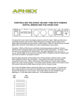
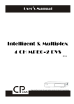
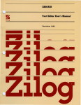
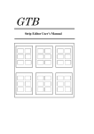
R E M O T E
-R
C O N T R O L L E R
FOR USE WITH
THE MODEL 1788 8-CHANNEL
MICROPHONE PREAMPLIFIER
USER’S GUIDE
R E M O T E
-R
C O N T R O L L E R
Copyright©1999 by Aphex Systems, LTD. All rights reserved. All Aphex products are
trademarks or registered trademarks of Aphex Systems, LTD. Other brand and product names are trademarks or registered trademarks of their respective holders.
Manual Production: KW Marketing Services
Printing: CitiPrint
2
TABLE OF CONTENTS
1.0 INTRODUCTION
1.1 The Model 1788-R Remote Controller
1.2 The 1788-R Remote Controller at a Glance
1.3 Quick Setup
2.0 FUNCTIONS
2.1 Overview
2.2 Selection and Validation Block
2.3 Preset Handling Block
2.4 Secondary Functions
5.0
4
6
8
8
9
3.0 INTERFACING
3.1 Interfacing
3.2 When Using the 1788 Remote Program
4.0
4
WARRANTY
4.1 Limited Warranty
4.2 Service Information
12
13
15
15
16
SPECIFICATIONS
3
R E M O T E
-R
C O N T R O L L E R
1.0 INTRODUCTION
1.1 THE MODEL 1788-R REMOTE CONTROLLER
To control up to sixteen Model 1788 8-Channel Microphone Preamplifiers from a remote location we
created the Model 1788-R Remote Controller. The 1788-R has been designed to closely match the layout
of the Model 1788, ensuring easy and familiar operation.
The 1788-R comes with preset handling which allows the user to create and instantly recall up to 60
presets, for "on-the-fly" changes during a session or live concert. Presets can also be loaded (recalled) on
demand by using MIDI Preset Change Commands allowing the 1788-R to be integrated in a fully automated show control system.
Communication between the 1788-R Remote Controller and the Model 1788(s) is based on a customized
MIDI SysEx protocol using a serial port connection (RS-232 or RS-422) or standard MIDI connections.
All connectors for the 1788-R are found on the separate power supply. It is possible to attach the 1788-R
and the power supply together or leave them as separate entities depending on the arrangement you
prefer.
If you are not yet familiar with all of the functionality of the Model 1788, please refer to the User’s
Manual that came with the unit since the 1788-R duplicates most of the main functions. Information
that is vital to both the Model 1788 and the 1788-R is ONLY supplied in the Model 1788 User’s Manual.
This includes material referring to the power connection, expanded explanations on the uses of the
communication ports, a wide assortment of hook-up diagrams and a pin configuration for all connectors.
This manual covers only those features, functions and interfacing configurations that are specific to the
1788-R.
1.2 THE MODEL 1788–R REMOTE CONTROLLER AT A GLANCE
This section is meant to serve as a quick reference to familiarize you with the controls found on the
1788-R Remote Controller. Further details are found in section 2.0 with regard to the Selection &
Validation Block, Preset Handling Block and Secondary Functions. Since the Local Block and Test Tone
Block are duplications of the same set of controls found on the Model 1788, we have not included
detailed explanations for those two sets of controls in this manual. Refer to the Model 1788 User’s Guide
for complete information on the proper use of the functions found in these two blocks of controls. For
your convenience, we have, however, included basic descriptions of the the Local Block and Test Tone
Block as a quick reference in this section.
SELECTION AND VALIDATION BLOCK
Valid LED
When LED light is a
solid color, it indicates
unit status.
Green = Connected
Red = Not Connected
When LED light is
flashing, it indicates
preset status.
Green = Load
Red = Selected
Comm LED
This LED illuminates
whenever data is
being received or
transmitted between
the 1788-R and the
Model 1788(s).
Clip/Lim LED
This LED serves a dual
purpose. The LED will
illuminate when either
clipping occurs or when
limiting occurs (MicLim™
must be activated).
4
Unit Select
Select one of 16
connected 1788’s
using these buttons.
Once selected, the
Local Block controls
and modifies the
settings of that
specific unit.
Comm Test
Initiates a communication test to verify
connection status of
all Model 1788(s) in
the system. This
button must be activated after power up
to start communication procedure.
1.0 INTRODUCTION
LOCAL BLOCK
Gain Select
Determines the function of the
GAIN control; Input, Main
Output or Aux Output.
Channel Status Readout
Displays input and output
gains settings, headroom,
and function status.
Channel Select
Chooses one of
eight channels
from the
currently selected unit.
Mute
Shut down the analog output of
the selected channel. All functions can be adjusted while a
channel is muted. This does not
effect digital output on Model
1788.
Multiple Select
Allows simultaneous
control of a group of
channels. When this
function is activated,
any channel selected
becomes part of the
group.
Phantom +48V
Engages the 48V phantom
power for condensor microphones.
Gain Control
Adjusts gain
setting for
selected
function;
Input, Main
Output and
Aux Output.
Polarity Reverse
Reverses polarity on
the input stage.
Enable Limiter
Engages the proprietary MicLm™
limiter.
Low Cut 75Hz
Engages a
12dB/octave low cut
filter with a corner
frequency of 75Hz.
26dB PAD
Inserts a 26dB PAD (attenuation) on the input stage.
PRESET HANDLING BLOCK
Status LEDs
Shows status of preset in the
NEXT display; Mismatch,
Empty or Protected.
Preset Readout
The CURRENT
display shows the
preset that is in use.
The NEXT display
shows the next
preset to be loaded.
Load
Loads preset displayed
in NEXT readout. This
initiates a download of
all current settings from
connected Model 1788s
(except in Preset Edit
Mode).
Protect/Unprotect
Toggling this switch protects
and unprotects presets. A
protected preset can not be
overwritten or erased.
Select
Selects the next
preset to be edited
or loaded. Selected
preset is displayed
in NEXT readout.
Preset Edit Mode
When activated, presets
can be edited without
transmitting control
data to the connected
Model 1788s.
Snap Shot
Used to take a snapshot
of the current settings
from all connected units.
This operation saves
settings into the preset
number that is shown in
the NEXT readout.
TEST TONE BLOCK
700 Hz Test Tone
Used to adjust system levels. One of two test
tone levels may be used. (0dBfs or -20 dBfs).
5
Erase
Erases preset
settings, turning
the selected preset
that is displayed in
NEXT readout into
an empty preset.
R E M O T E
-R
C O N T R O L L E R
1.3 QUICK SETUP
The following instructions are a quick start for setting up the 1788-R with a single Model 1788 or a
bank of Model 1788s. The Model 1788s should already be installed. If they are not installed, refer to the
Model 1788 User’s Guide.
To interface the 1788-R, it must first be connected to the power supply via a DB-25 connection. Use
either the supplied parallel cable or any standard parallel DB-25 cable. The maximum cable run for
guaranteed operation is ten feet.
Using either the RS-232 or RS-422 DB-9 connectors on the 1788-R Power Supply (labeled “To Preamp”)
to connect the 1788-R to the Link In (RS-232/RS-422) on the first Model 1788 in the system using the
appropriate connection cable. Use a null modem cable when connecting via RS-232 and a standard
serial mouse/monitor extension cable when connecting via RS-422.
Note: On older Model 1788’s the DB-9 connectors are labeled Master RS-232 and RS-422.
For long communication distance (> 100 feet, 33 meters) always use the RS-422 communication link.
For shorter distances choose between RS-232 and RS-422 based on availability of the proper communication cable.
Place the 1788-R Power Supply either on the floor close by the remote or if the remote is mounted in a
rack the power supply can be physically attached to the back of the remote. Four screws are supplied
for that purpose.
1788-R HOOKUP
DB-25 Cable
TO CONTROLLER
TO 1788-R CONTROLLER
TO PREAMP
RS-232
TO POWER SUPPLY
RS-232
RS-422
RS-422
1788-R Controller
UTIL
1 2 3 4
ON
MIDI
OUT
IN
THRU
1788-R Power Supply
MIDI
OUT
P
<
IN
˙
˙
UTIL
THRU
Link In RS-232
AES/EBU OUTPUT
1 2 3 4
AUX
OUTPUT
Ch 8
Ch 7
Ch 6
Ch 5
Ch 4
Ch 3
Ch 2
Ch 1
ON
Link In RS-422
90-260 VAC 50/60 HZ 60 WATTS
ADAT
IN
WORD
OUT
CLOCK
˙
˙
OPTICAL
Link Out RS-422
TDIF-1
˙
MODEL 1788 - 8 Channel Mic Pre
Aphex Systems Sun Valley, CA
First Model 1788 in system chain
Refer to sections 3.0 for more details on interfacing the 1788-R into a system, particularly
a system running the proprietary, PC-based, 1788 Remote Program.
6
1.0 INTRODUCTION
The following step-by-step instructions will first assist you in configuring the Model 1788(s) into a
system so they will be recognized by the 1788-R and then you are guided through a comm test procedure. Finally, we show how presets are created, loaded and changed.
On the Model 1788
1. Tap the LOCAL CONTROL button (so it illuminates) on all connected Model 1788s.
2. On the first Model 1788 in the chain, press SET PORT to select RS-232 or RS-422 (depending on
port used to connect to 1788-R). Select the RS-422 for the reminder of units in the chain.
3. Toggle the SELECT button until the baud rate of 19.2kHz is displayed in the status readout.
4. Press the MIDI button until the LED marked “Chan.” illuminates, then select MIDI channel 1 by
toggling the ADJUST button until the status readout displays “ch1”. All units must be set to channel 1.
5. After the channel has been selected on all units, press MIDI button once again so that the LED
marked “Dev.” is illuminated. Select Device 1 as the first unit in system by toggling the ADJUST
button until the status readout displays “dev1”. For each remaining Model 1788 in the chain follow
the same procedure and select “dev 2”, “dev 3” and so on.
On the 1788-R
6. Tap on the COMM TEST button so it illuminates. The 1788-R will now perform a series of tasks
with all connected Model 1788s. The completion of the communication test is indicated by the illumination (green) of the VALID LED for all connected units and the COMM TEST button will no
longer be lit. The COMM TEST button will flash during test procedure. At the end of comm test,
unit 1 is selected as the default unit. All settings from each connected Model 1788 are loaded into
the 1788-R during the Comm Test.
7. Select desired unit with the corresponding UNIT SELECT button. Make sure the VALID LED is
green. Only a validated unit may be selected.
8. The Local Block now reflects the settings for that specific unit. Changes to that unit can now be
made directly from the 1788-R.
9. Continue steps 7 & 8 with all connected units and make any desired changes to each unit.
10. To save all settings of the units in the system, you want to create a preset. This is accomplished by dialing in the desired preset number with the SELECT knob and pressing the SNAP
SHOT button. This will copy the created preset number into the current (loaded) display. The three
preset status LEDs will now reflect the status of the newly selected preset.
11. Repeat steps 7-10 to create/edit presets at will.
12. To load already created presets into the connected 1788-R, dialup the desired preset number so
it is displayed in the NEXT display. To load that preset (making it the CURRENT preset), press the
LOAD button. The selected preset number will now be displayed in the CURRENT display panel.
Note: The Comm LEDs for all the connected units are illuminated when presets are
loading. You must wait for the LEDs to turn off before proceeding. For more info on
working with presets refer to Section 2.3.
7
R E M O T E
-R
C O N T R O L L E R
2.0 FUNCTIONS
2.1 OVERVIEW
The 1788-R Remote Controller provides all the functions from the Model 1788’s Local Block and Test
Tone Block. For complete details on the functions in both these blocks, refer to the Model 1788 User’s
Manual. A quick reference to these basic functions is found in this manual’s Section 1.2 -The 1788-R
Remote Controller at a Glance.
The following two sections provide further details beyond what was in the quick reference for the
Selection and Validation Block and the Preset Handling Block.
There is also a set of Secondary functions; Clip/Lim Metering ballistics, brightness control and software
version display, which is explained in Section 2.4.
2.2 SELECTION AND VALIDATION BLOCK
The upper portion of the 1788-R is used for selecting and validating all Model 1788s in a system chain.
The COMM TEST button initiates a communication test, which verifies the connection status of all
Model 1788s in the system. The COMM TEST button and the VALID LED’s will flash during the test
procedure. At the end of the test, identified units will be indicated by a solid green light in the respective
VALID LED‘s and the COMM TEST button will stop flashing.
Whenever a Model 1788 is added to the system or right after power up, it’s recommended that you run a
communication test, though a communication test can be run at any time just to check status of the
Model 1788s. If changes are made locally on one or more of the connected Model 1788s, the communication test can be run to upload all new settings.
The VALID LED indicates the communication status of all units identified under the communication test.
A solid green light means valid communication, solid red light means invalid communication. Under
normal operation the VALID LED should never turn red. If the Valid LED should turn red, inspect the
cabling between the Model 1788’s, and the settings in the control block, then rerun the communication
test. After the communication test only the valid units may be selected using the UNIT SELECT button.
Specific units are selected with the UNIT SELECT buttons (illuminates when selected). When a unit is
selected all specific unit settings are transferred to the 1788-R. In Preset Edit Mode the number of units
in a preset can be modified by using the UNIT SELECT buttons. Please refer to the next Section 2.3
–Preset Handling Block.
During the time the remote is communicating (sending or receiving information) the COMM LED will
illuminate. When one or more COMM LED’s are illuminated no new functions can be activated.
The CLIP/LIM indicator illuminates when any one of the eight channels of that particular unit is clipping
or when limiting occurs (if MicLim™ circuit is activated). To determine which channel is exhibiting clipping or limiting, select the unit in question with the UNIT SELECT button and the Local Block CLIP/LIM
LED indicator for the individual channel or channels will illuminate. To be able to indicate a short
Clip/Lim event the Model 1788-R has a build-in programmable Clip/Lim memory function. This function keeps the Clip/Lim LED (both in the Local Block and the Selection and Validation Block ) illuminated
for a certain amount of time. This user programmable function is explained in Section 2.4 - Secondary
Functions.
8
2.0 FUNCTIONS
2.3 PRESET HANDLING BLOCK
In applications using multiple Model 1788’s, such as theater and live concerts, it is critical that mic
preamp settings can be stored and changed quickly as Presets. The Model 1788-R is a state-of the-art
solution that not only duplicates the key functions of the Model 1788 but provides a means to quickly
recall a series of settings that are used in every performance.
From the Preset Handling Block presets are created (SNAP SHOT), loaded (recalled), edited and erased.
The readout displays two different digital numbers representing individual presets. The CURRENT readout indicates the loaded preset number (preset in use), while the NEXT readout indicates the next preset
to be loaded (which becomes the next preset in use). After power up the CURRENT readout will contain
two dashes until the comm test has been run and a preset loaded.
Note: While in the Preset Edit Mode the CURRENT display indicates which preset is
currently being modified. It DOES NOT indicate which preset is currently loaded to the
connected Model 1788’s.
If any presets are created on the Model 1788-R, the LOAD button will illuminate just after the comm
test, indicating the ‘Next’ selected preset is ready to be loaded into the connected Model 1788(s). Loading
a preset initiates a download of all current settings. The preset change is done when the Comm LED is
no longer illuminated.
To select the next preset, turn the SELECT knob to the desired preset which is displayed in the NEXT
readout. Pressing the LOAD button, loads the preset into the controller and shifts the preset number
from the NEXT readout to the CURRENT readout.
When selected a new preset with the SELECT knob, the three LEDs next to the readout indicate the
preset’s status as follows:
MISMATCH - when the number of units in the selected presets do not match the number of units
detected in the comm test. A preset can still be loaded even when mismatch occurs.
PRESETS EMPTY - no preset found.
PROTECTED – the preset is locked and cannot be overwritten or erased.
The PROTECT/UNPROTECT button can be used as a second level of protection to prevent accidental
overwritting of any or all created presets. Use the PROTECT/UNPROTECT button to toggle the protection
status of any preset. If you want to make a SNAP SHOT of a protected preset, the preset has to be
unprotected. All new presets (created with SNAP SHOT) are automatically protected.
To ERASE a preset, select the desired preset with the SELECT knob (appears in NEXT display) and
press the ERASE button. For instance, in order to prevent any confusion an invalid preset can just be
erased, removing it from the list of available presets. Preset number 1 can not be erased, as it is the
default preset in the preset edit mode.
The SNAP SHOT button is used to create a new preset or edit an existing preset. When creating a new
preset:
1. Make necessary settings on all Model 1788s
2. Use the SELECT knob to dial up a new preset number. Selection appears in NEXT display.
3. Press SNAP SHOT to create the preset, automatically shifting the preset to the CURRENT readout, indicating that is the preset in use.
When editing an existing preset:
1. Select the desired preset number with the SELECT knob. Selection appears in NEXT display.
2. Load the preset by pressing the LOAD button. The preset shifts to the CURRENT display.
3. Make setting changes on all units. If the preset is protected it must be unprotected at this time.
An existing preset can not be updated if it is protected.
4. Press SNAP SHOT to overwrite the preset with the new settings.
9
R E M O T E
-R
C O N T R O L L E R
Activating the PRESET EDIT button (illuminates when activated) allows a user to edit an existing
preset(s) without transmitting control data. This means that a preset can be selected and modified using
the Local Block without actually transmitting the changes to the selected unit. This makes it possible to
change settings for an upcoming preset, for example the next preset used in a live show, without interfering with the current settings of the connected Model 1788s. Presets can also be modified without
having the modified 1788’s connected or without running the COMM TEST.
The Preset Edit Mode can be used as follow:
1. At any time, it is possible to enter the Preset Edit Mode by pressing the PRESET EDIT button.
When entering the preset edit mode, the 1788-R automatically loads the preset in the CURRENT
readout. If no presets have been loaded, preset #1 is chosen as the default preset. To edit a new
preset continue with steps 2 and 3.
2. Use the SELECT knob to select a preset number, which appears in the NEXT display. The VALID
LED’s will flash red to indicate which unit’s are present in the selected (next) preset.
3. Press the LOAD button to load the selected presets data into the 1788-R’s memory without
transmitting this data to the connected Model 1788’s. The VALID LED’s will now flash green to
indicate that the selected (next) preset is ready to be loaded into the 1788-R.
4. Select the unit you want to modify with the UNIT SELECT buttons. Make all desired function
changes in the Local Block. Repeat this step for all the units you want to modify.
5. To save the new settings select the ‘Next’ preset number (using SELECT knob) in which the
changes will be saved and press the SNAP SHOT button. (If the selected preset is protected first
unprotect it by pressing the UNPROTECT button or the new setting will not be saved.)
6. Exit the Preset Edit Mode by pressing the PRESET EDIT button again (LED will no longer be illuminated) The 1788-R will now upload all settings from the connected Model 1788’s. Uploading for
each connected unit is indicated by the illumination of that units respective red comm test LED on
the 1788-R.
Note: If the Preset Edit Mode is exited without first saving the changes by pressing the
SNAP SHOT button, all changes will be lost.
In the Preset Edit Mode it is also possible to add/remove units from a preset.
To add a unit, press the UNIT SELECT button that is next to the last connected unit that shows a
flashing green VALID LED. The new unit selected will now be added to the preset containing the
same function settings as the unit with the unit number just before itself. For instance, if unit #4 is
added to a preset it will, by default, contain the same functions as unit #3. To indicate that this
unit now is a part of the preset, the corresponding VALID LED will start flashing green.
Use the ERASE button to remove a unit from a preset. Only the last unit in a preset can be
removed (one at a time). Select the unit with the UNIT SELECT button and press the ERASE
button. To indicate that a unit has been removed from a preset, the corresponding VALID LED will
no longer be flashing.
To save the changes after adding or removing a unit(s) from a preset make a SNAP SHOT of the settings
to the desired preset number.
10
2.0 FUNCTIONS
2.4 SECONDARY FUNCTIONS
The 1788-R has a set of functions not directly accessible from the front panel. These functions, named
secondary functions, are accessed by pressing down both TEST TONE buttons and a pre-designated
CHANNEL SELECT button. To Exit this mode, press any key.
CLIP/LIM MEMORY FUNCTION. (Press both TEST TONE buttons and CHANNEL SELECT #6).
To be able to indicate a single, fast Clip/Lim event and give the user of the 1788-R a chance to
react to the event, the 1788-R’s Clip/Lim indicators has a built-in user-definable memory function.
This means every time the remote receives a signal level meter feedback indicating a Clip/Lim situation, the related LED (Local Block and Selection and Validation Block) will illuminate for a predefined period of time. Each time the remote receives a new feedback telling that the same channel
is in a Clip/Lim situation the time is reset. The time is programmable in steps 0 to 4 equaling the
times of 1,6,12,18 and 24 seconds. The memory time is adjusted by rotating the GAIN CONTROL
knob, and the adjusted time appears in the status display.
When a Clip/Lim situation is received for a unit not selected with the UNIT SELECT buttons, the
CLIP/LIM LED for that specific unit will illuminate ONLY in the Selection and Validation Block. By
selecting the unit with the UNIT SELECT button while the CLIP/LIM LED is illuminated, the memory time is reset, and the Local Block now indicates (using the independent channel CLIP/LIM
LED’s), which channel(s) was causing the Clip/Lim situation to occur in the first place.
Note: This programmable Clip/Lim Memory Function gives the user a change to react to a
single Clip/Lim situation that otherwise would have been impossible to detect without
constant monitoring of the signal level meter from all channels in use.
DIMMING (Press both TEST TONE buttons and CHANNEL SELECT #7)
To enable your Model 1788-R to integrate into varying lighting conditions, we have added the capability to adjust the brightness of the front panel display. The brightness level is set in steps from 0
to 4 (4 is brightest). Brightness is adjusted by rotating the GAIN CONTROL knob, and the adjusted
level appears in the status display. To exit this function, press any button on the front panel.
FLASH PROGRAM VERSION (Press both TEST TONE buttons and CHANNEL SELECT #8).
To verify which Flash Program Version your 1788-R is running, the version number can be
displayed in the Preset Handling Block’s display. At the time of publication, the current version was
"FL B". You can get new software releases on our web site, www.aphex.com, posted under downloads or you can contact Aphex Systems’ customer service.
11
R E M O T E
-R
C O N T R O L L E R
3.0 INTERFACING
3.1 INTERFACING
The main advantage of the Model 1788 is its ability to be controlled remotely, allowing the unit to be
located near the microphones, providing many sonic and operational benefits. The audio industry has
accepted for years the necessity of running microphone lines from the microphone back to the mix position. Once at the mixing console (or dedicated microphone preamp) the microphone levels are amplified
to line levels. Advancements in digital and fiber technology with regards to audio transmissions have
created a demand for amplification of microphone levels closer to the microphones. While a fixed gain
stage may work for many applications, anyone who has mixed a live show or has done a tracking
session knows there will inevitably be adjustments made to the microphone preamps. Absent an engineer riding gain at the preamps, remote control becomes a necessity.
With the 1788-R (or the 1788 Remote Program) it’s possible to create and save presets. By using presets,
gain and function settings from all connected Model 1788s in the system chain can be saved and
recalled seamlessly. Several groups of channels along with any number of individual channels can be
controlled directly from the 1788-R.
Standard MIDI, RS-232 and RS-422 communication ports are provided on the 1788-R’s external power
supply for connecting the 1788-R to a bank of Model 1788’s. No matter what port is selected the protocol will always be MIDI, although the communication standard will vary.
The RS-232 and RS-422 ports are functionally the same, however the length of cable that can be used is
variable. Moreover, there is a significant different in the noise immunity between the two connections.
The following table supplies the key differences of the two connectors.
Connection
Noise Immunity
Max Length
RS-232
Low
100 ft, 33m
RS-422
High
3000 ft, ~1km
Cable Type
Null Modem
Standard Pin-To Pin Serial
(monitor mouse extension cable)
Refer to Section 3.8 (Communication Ports) in the Model 1788 User’s Guide for detailed
illustrations and pin configurations of these connections.
Using MIDI as a Secondary Control Input
On the power supply that contains all connections for interfacing the 1788-R, there is a dip switch to
select between the MIDI or RS-232/RS-422 “To Controller” port when using a secondary controller such
as a PC loaded with the proprietary 1788 Remote Program. Only the switch marked “1” is used. In the
up position, MIDI is chosen and in the down (factory default) position, RS232/RS-422 is selected.
We have including MIDI connectors on the 1788-R to provide the capability of synchronized preset
changes from a MIDI device ( such as digital mixing consoles and DAW workstations), thus making the
1788-R part of an automated show control system. In this configuration, the 1788-R is used as an interface between another MIDI-based device and the Model 1788 (using RS-232/RS-422). Due to the different baud rates between MIDI (31.25kHz) and RS-232/RS-422 (19.2kHz) care must be taken when the
1788-R is used in this fashion because communication overflow can occur.
When receiving a MIDI preset change command, the 1788-R will load the preset corresponding to the
received preset change number. This preset number will be displayed in the CURRENT display. If the
received preset number corresponds to an empty preset, the MIDI preset change command will be
ignored. MIDI preset change commands will still load a MISMATCH preset.
12
3.0 INTERFACING
Note: The baud rate for the RS-232/RS-422 is fixed at the factory to the default 19.2kHz
on the 1788-R to match our proprietary 1788 Remote Program for PCs.
Refer to Section 5.8 in the Model 1788 Users Manual for details on MIDI protocol and
MIDI commands with respect to controlling Model 1788s remotely.
Using the RS-232/RS-422 Communication Ports as Secondary Control Input
To synchronize the 1788-R with a PC running our proprietary 1788 Remote Program use either the RS232 or RS-422 connection (under the heading “To Controller”) on the 1788R’s separate power supply
box. The 1788-R’s Dip Switch #1 must be in the off (down) postion to ensure proper communication
between the 1788-R controller and the PC. (See diagram in the next section.)
3.2 WHEN USING THE 1788 REMOTE PROGRAM
Up to sixteen Model 1788s may be daisy-chained together and controlled remotely via the 1788-R
Controller and or the 1788 Remote Program. While both the controller and the program have detailed
instructions on their use in separate manuals, this is the only section that addresses using both the
controller and the remote program together.
While the 1788-R is fast and intuitive, duplicating the majority of functions found on the unit’s front
panel, it can be useful to use the 1788 Remote Program alongside the 1788-R due to certain advantages
it offers.
For instance, each Model 1788 in the system as well as all of their individual channels can be given a
specific alphanumeric name, making it much easier to identify as many as 16 units and 128 channels.
Presets can be saved as files on the remote program, immediately loading up from a Project File. The
1788 Remote Program provides a monitoring window to watch channel levels on several units simultaneously. The 1788-R can only monitor levels on one unit at a time. Compared to the numbered presets on
the 1788-R, the 1788 Remote Program can save presets with user-defined names making recall of
presets easier and time efficient.
When the 1788-R is used with the 1788 Remote Program, the 1788-R must be set up as the primary
controller. The prime controller is the first device to receive remote commands from the Model 1788(s). It
also passes on the same data (like a through port) to the PC with the remote program installed, enabling
synchronization. As this is the case, its important to note that when the prime controller fails, the entire
system fails.
The illustration on the following page shows how to interface a 1788-R and a PC loaded with the 1788
Remote Program.
Note: When the 1788-R is connected to a PC via the RS-232 or RS-422 port it is not possible to simultaneously use its MIDI connectors.
13
R E M O T E
-R
C O N T R O L L E R
PC TO 1788-R (PRIME CONTROLLER) TO MODEL 1788
PRIMARY
CONTROLLER
To 1788R
Controller
TO CONTROLLER
TO 1788-R CONTROLLER
TO PREAMP
RS-232
RS-232
RS-422
RS-422
UTIL
1 2 3 4
ON
MIDI
OUT
IN
THRU
MIDI
OUT
P
<
IN
˙
˙
UTIL
THRU
Link In RS-422
ADAT
Ch 8
Ch 7
Ch 6
Ch 5
Ch 4
Ch 3
Ch 2
IN
WORD
OUT
CLOCK
˙
Ch 1
˙
OPTICAL
Link Out RS-422
SECONDARY
CONTROLLER
AUX
OUTPUT
ON
90-260 VAC 50/60 HZ 60 WATTS
PC running proprietary
1788 Remote Program
AES/EBU OUTPUT
1 2 3 4
Link In RS-232
To Serial Port
(RS-232)
TDIF-1
˙
MODEL 1788 - 8 Channel Mic Pre
Aphex Systems Sun Valley, CA
First Model 1788 in system chain
When the 1788-R is linked to a PC loaded with the 1788 Remote Program, it is possible to exchange
preset data in either direction. To administer this exchange open the ‘1788-R Link’ found in the Preset
Handling Window in the Tools Menu of the 1788 Remote Program.
1788-R LINK MENU FROM 1788 REMOTE PROGRAM
A dialog box will appear offering three choices.
• Upload Presets from 1788-R to 1788 Remote Program - Remember the 1788-R preset numbers
are not always continuous. When uploading to the 1788 Remote Program, the presets will be
renumbered in sequence during the upload.
• Download Presets to 1788-R - Presets are downloaded according to the 1788 Remote Program’s
preset list.
• Download Scenes to 1788-R - Instead of downloading from the preset list, presets are downloaded
in the order allocated by each scene. Even though scenes are in non-sequential order they will be
loaded into the 1788-R sequentially. (It is possible for the same preset to be applied to different
scenes, which means the same preset can be downloaded to several preset locations.
The advantage of exchanging preset data from the PC to the 1788-R, is the user-defined names that can
be saved in the 1788 Remote Program. Calling up a preset you know by name or that is named according to the show plan can be much simpler than trying to remember numbered presets.
14
4.0
WARRANTY
4.1 LIMITED WARRANTY
Aphex Systems, Ltd. warrants to the original purchaser that the Model 1788 will be free from
defects in materials and workmanship for a period of one (1) year from the date of purchase.
The above warranty is in lieu of any other warranty, whether expressed, implied or statutory,
including, but not limited to, any warranty of merchantability, fitness for any particular
purpose, or any warranty arising out of any proposal, specification or sample. Aphex
Systems, Ltd. shall not be liable for incidental or consequential damages. Aphex Systems,
Ltd. neither assumes nor authorizes any person to assume for it any other liability.
4.2 SERVICE INFORMATION
If it becomes necessary to return this unit for repair, you must first contact Aphex Systems,
Ltd. for a Return Authorization Number, which will need to be included with your shipment
for proper identification. Repack this unit in its original carton and packing material, along
with a letter explaining the symptoms and or/defect(s). Be sure to reference the Return
Authorization Number. If you believe the problem should be covered under the terms of the
warranty, you must also include proof of purchase. Insure your shipment and send it to:
Aphex Systems, Ltd.
ATTN: RA# (enter RA # here)
11068 Randall Street
Sun Valley, CA. 91352
PH: (818) 767-2929 FAX: (818) 767-2641
CAUTION: To reduce the risk of fire or electrical shock, do not expose this device to
rain or moisture. Do not operate this unit with the metal chassis cover removed.
This equipment has been tested and found to comply with the limits for Class A
digital device pursuant to Part 15 of the FCC Rules. These limits are designed to
provide reasonable protection against harmful interference when the equipment
is operated in a commercial environment. This equipment generates, uses, and
can radiate radio frequency energy and, if not installed and used in accordance with the operating guide, may cause interference to radio communications. Operation of this equipment in
a residential area is likely to cause interference in which case the user will be required to
correct the interference at his own expense. The user is cautioned that changes and modifications made to the equipment without approval of the manufacturer could void the user’s
authority to operate this equipment. It is suggested that the user use only shielded and
grounded cables to ensure compliance with FCC Rules.
!
15
5.0
SPECIFICATIONS
CONNECTORS
Type:
“To Controller”
RS-232, RS-422, MIDI
“To Controller”
RS-232, RS-422
OTHER
Power
60 VAC
Dimensions
3.5” H x 19” W x 13.25” D
(88.9mm x 482.6mm x 336.55mm)
Weight
2 lbs.
Aphex Systems, Ltd. • 11068 Randall Street • Sun Valley, CA 91352
PH: (818) 767-2929 FAX: (818) 767-2641
Copyright©1999 by Aphex Systems, LTD. All rights reserved. All Aphex products are trademarks
or registered trademarks of Aphex Systems, LTD. Other brand and product names are trademarks or registered trademarks of their respective holders.
All features and specifications are subject to change without notice.