1
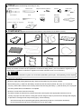
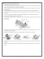
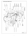
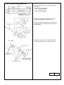
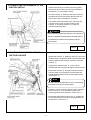
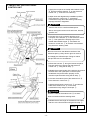
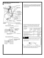
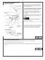
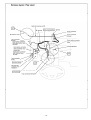
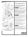
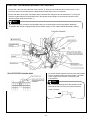
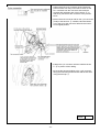
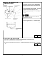
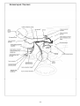
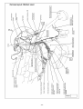
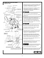
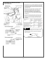
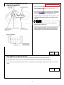
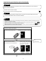
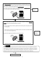
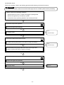
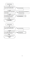
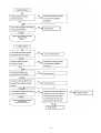
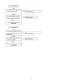
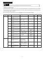
REMOTE ENGINE STARTER
MZ360360EX
INSTALLATION INSTRUCTIONS
Applicable Models
GALANT(09.5MY-), ECLIPSE/SPYDER(10MY-), ENDEAVOR(09MY-)
!
Warning
This system is exclusively for automatic transmission vehicles. Never install this system on manual
transmission vehicles.
Thank you for purchasing the Mitsubishi Genuine Accessory.
To install and use the product correctly with proper knowledge of it, read this publication carefully.
Keep this publication for reference when maintenance is required.
Attention
- This publication gives precautionary instructions in the boxes titled as follows.
Read through these instructions thoroughly.
Warning
!
!
Caution
Describes precautions that should be observed in order to prevent serious injury or
death to the user.
Describes precautions that should be observed in order to prevent injury or damage
to the vehicle or its components, which may occur if sufficient care is not taken.
Note
Provides additional information that facilitates installation work.
- Failure to follow these instructions not only prevents the product from working properly but may lead to trouble
with the vehicle. Be sure to follow all instructions carefully.
- If there is anything unclear about the installation, handling and/or usage of the product, contact your Mitsubishi
Motors dealer for clarification.
- Mitsubishi Motors Corporation is not responsible for any defects or difficulties caused by or resulting from the
failure to follow given instructions.
- We recommend you to have the installation performed at an authorized Mitsubishi Motors dealer.
To the dealer:
Be sure that the customer receives this publication.
ZZ100-00420-0
10, 8
■ TOOLS (Make the following tools ready for use.)
Socket wrench (10mm)
Trim remover
Extension bar
Phillips screwdriver (medium)
Scale
Isopropyl alcohol or degreaser
Vinyl tape
Scissors
Cutting pliers
Multimeter
Pliers
Shop towel
■ COMPONENTS (Make sure that all of the following components were included in the kit.)
① Electronic control unit
(ECU):1
②Antenna unit:1
③Harness:1
④Urethane sheet:1
⑤Protective sheet:1
⑥Double-sided Adhesive tape:2
⑦Tie-wrap:17
⑧Sub harness for hood
1
Switch* :1
⑩Installation Instructions:1
(this document)
⑪Owner’s Manual:1
2
⑨Remote controller* :1
*1:For GALANT without theft alarm system
*2:Only one remote controller can be registered to a vehicle for safety reason. (It is not possible to register two or
more remote controllers to a vehicle nor register one remote controller to two or more vehicles.)
Note
On GALANT without theft alarm system, the hood switch (Mitsubishi genuine part, sold separately) is also required.
■ PRECAUTIONS
- Be sure to apply the parking brake securely. Remove the ignition key from the key cylinder.
- Disconnecting the (–) cable from the battery causes the radio and audio presets, the clock, etc. to lose their
memory. Record the contents of the memory before disconnecting the battery (–) cable to allow you to reprogram
the radio presets after the installation is completed.
- Be sure to connect the connectors securely.
- At positions where the harness may interfere with other vehicle parts, take appropriate measures such as
winding vinyl tape over the harness or fixing the harness using tie-wraps to prevent it from damage and dangling.
- To prevent the cut edges of tie wraps causing injury, do the following:
- Wind the tie wrap with its protruding part pointing downward (so that its cut end points downward).
- Cut off the excess tie wrap close to the head. Do not cut at an angle.
-2-
Before installation
- Be sure to disconnect the
negative terminal cable from
the battery.
When installing or removing parts
- Loosen or tighten bolts and
- Use a Phillips screwdriver that - To remove plastic parts, use a
nuts using tools that match their fits the recess in the head of the trim remover.
sizes.
screw being loosened or
tightened.
Wiring
- When disconnecting connectors, - When connecting connectors,
first unlock them, then separate
push them against each other
the connectors by pulling on
until the lock clicks.
themselves, not on cables.
click!
- Do not pull on wiring harnesses
strongly.
- Do not let harnesses be pinched
between parts.
click!
click!
- Route the harness away from hot - Protect the harness from sharp
- Apply sealant to grommets at
components such as the engine
edges by covering the edges with portions where the harness run
and radiator.
tape or other suitable materials.
through.
Clamping harness
- Fasten the additional harness
to an existing vehicle harness
using tape or tie wraps.
- Do not fasten the harness to
brake pipes or high pressure air
conditioner pipes.
After installation
- Bind up extra length of the
harness using a tie wrap.
- Check the product and wiring
for installed condition before
connecting the cable to the
battery.
- Check the installed product for
function. Also check lamps,
horn, wipers, etc. for proper
operation.
Beep
- If one tie wrap is too short, use
two connected together.
-3-
■ QUICK SPLICE CONNECTOR
Precautions for installing quick splice connector
- Be careful not to damage the vehicle harness when cutting the vinyl tape wound around the harness to expose
the wire to which the quick splice connector is to be installed.
- When connecting a quick splice connector, confirm that a click is heard and also visually check that its two locks
are engaged firmly.
- Before installing a quick splice connector, re-check the colors of the two wires to be connected and also the
connector terminal number from where the wire to which the connector is connected comes to prevent incorrect
connection.
- If two or more quick splice connectors are to be installed on adjacent wires, do not install them side by side
but stagger them to prevent interference between them.
- If its two locks are engaged securely, the quick splice connector will still perform properly even if its hinge breaks.
1) If the wire of the vehicle harness to which the connector is installed is covered with vinyl tube or vinyl tape, cut
it off properly and expose the wire.
2) Insert the wire of the vehicle harness firmly into the guide groove of the quick splice connector.
3) Fold the connector, then press the connector with a pair of pliers as shown until it clicks and the two locks are
engaged.
4) After confirming that the connector is connected firmly, wind vinyl tape around the connector to prevent it from
rattling.
-4-
INSTALLATION PROCEDURES FOR ECLIPSE/SPYDER
A. PREPARATORY WORK
1) Confirm that the ignition key is removed and all the
electrical switches are off. Then disconnect the
battery (–) cable from the battery.
2) Remove the following parts in accordance with the
workshop manual.
1. Instrument panel side cover
2. Instrument lower panel assembly
3. Steering column upper cover
4. Steering column lower cover
5. Combination meter assembly
6. Cowl side trim
7. Front pillar trim
Check
B. ROUTING THE HARNESS
1) Route the harness ③ along the vehicle harness as shown in the following two drawings.
!
Caution
Do not fix the harness ③ yet. It should be fixed after completing all the connecting works.
Note
Details of sections C to H are shown in the following steps.
-5-
-6-
-7-
C. INSTALLING THE ANTENNA UNIT
1) Cut the urethane sheet ④ into the following
dimensions.
A: 35 x 140 mm (2 pieces)
B: 70 x 20 mm (4 pieces)
C: 70 x 70 mm (1 piece)
D: 70 x 10 mm (1 piece)
A
B B B B
C
D
A
2) Wrap the two pieces of urethane sheet A ④
around the cable of the antenna unit ②.
3) Pass the cable of the antenna unit ② into the
backside of the instrument panel at the bottom of
the front pillar.
4) Bind the antenna unit ② to the roof harness
using the three pieces of urethane sheet B ④.
Check
-8-
D. CONNECTING THE HARNESS TO THE
IGNITION SWITCH
1) Disconnect the 6-pin connector from the ignition
switch and connect the 6-pin connector (female) of
the harness ③ to the ignition switch.
2) Fix the harness ③ leading to the 6-pin connector
(female) to the instrument panel harness near the
branch to the disconnected 6-pin connector.
3) Turn back the disconnected 6-pin connector and
connect it to the 6-pin connector (male) of the
harness ③. Route the harness ③ along the
instrument panel harness.
!
Caution
Tilt the steering wheel up and down to check that no
tension is applied to the harnesses and that there is
no interference between the harnesses and the
vehicle parts.
Check
E. ROUTING THE HARNESS AROUND
THE FUSE HOLDER
1) Route the harness ③ leading to the 6-pin connector
(male) along the instrument panel harness and bundle
these harnesses near the 6-pin connector using the
tie-wrap ⑦.
2) Apply the protective sheet ⑤ over the knee
absorber bracket to prevent damage to the harnesses.
3) Route the harness ③ along the instrument panel
harness at the front of the deck crossmember and
bundle these harnesses near the fuse holder using
the tie-wraps ⑦.
Note
Use the harness clip marked with “★” in the drawing
as a reference for the tie-wrap position.
4) Pass the 13-pin connector and the 12-pin connector
of the harness ③ over the steering shaft to the
mounting position of the electronic control unit ①.
5) Route the cable of the antenna unit ② passing the
front of the ETACS-ECU to the mounting position of
the electronic control unit ①.
Check
-9-
F. INSTALLING THE ELECTRONIC
CONTROL UNIT
1) Apply the two pieces of double-sided adhesive tape
⑥ and the urethane sheet B ④ on the electronic
control unit ① as shown in the drawing.
2) Wipe clean and degrease the installation position
of the electronic control unit ① at the deck
crossmember stay above the steering shaft using
isopropyl alcohol or degreaser.
!
Caution
- Perform this work in a well-ventilated space.
- Never use organic solvent such as thinner, benzine,
gasoline, etc.
3) Connect the 13-pin connector and the 12-pin
connector of the harness ③ to the electronic control
unit ①. Then peel off the backing strips of the
double-sided adhesive tape ⑥ and attach the
electronic control unit ① to the deck crossmember
stay above the steering shaft.
!
Caution
Be sure not to touch the adhesive surface of the
adhesive tape by a dirty hand or glove or remove
and reapply the adhesive tape. Doing so makes
the tape lose much of its adhesion.
4) Route the harness ③ along the instrument panel
harness and fix the harness near the electronic
control unit ① using the tie-wrap ⑦.
5) Bundle the excess lengths of the wires to the ground
terminal and to the quick splice connector (with
white/black wire) and fix them properly on the
instrument panel harness using the tie-wrap ⑦.
6) Connect the antenna jack of the antenna unit ②
to the electronic control unit ①.
7) Secure the electronic control unit ① and also the
cable of the antenna unit ② on the deck
crossmember stay using the tie-wraps ⑦.
!
Caution
Route the cable of the antenna unit ② so that it
does not interfere with the steering shaft.
8) Bundle the excess length of the antenna unit cable
and fix it to the front harness using the tie-wrap ⑦.
Check
- 10 -
G. ROUTING THE HARNESS AROUND
THE ETACS-ECU
1) Connect the 1-pin connector (female) of the harness
③ to the 1-pin connector of the front harness taped
with the black tape on the front harness at the front of
the ETACS-ECU.
2) Connect the three quick splice connectors of the
harness ③ to the wires from the gray and white
24-pin connectors connected to the ETACS-ECU
as follows.
Note
The connector drawings show the positions of the
terminals as seen from the front (arrow direction)
of the connector.
3) Bundle the excess lengths of the wires and fix them
to the vehicle harness using the tie-wraps ⑦.
- 11 -
4) Disconnect the 3-pin connector of the instrument
panel harness from the junction block. Draw out the
No. 3 terminal from the connector and install the
terminal with red/green wire of the harness ③ to
that cavity. Reconnect the connector to the junction
block.
5) Disconnect the connector half on the 1-pin connector
(male) of the harness ③. Install the terminal drawn
out in step 4) to that connector half and reconnect it
to its original position.
6) Fix the 1-pin connector as shown in the drawing
using the tie-wrap ⑦.
7) Bundle the excess length of the harness ③ leading
to the 1-pin connector and fix it to the instrument
panel harness using the tie-wrap ⑦.
Check
- 12 -
H. ROUTING THE HARNESS TO THE
COMBINATION METER
1) Route the quick splice connector with white/black
wire and the ground terminal of the harness ③ to
the combination meter.
2) Connect the quick splice connector with white/black
wire to the black/white wire from the No. 13 terminal
of the 18-pin connector for combination meter.
3) Wrap the connector with the urethane sheet C ④
as shown in the drawing to prevent the connector
from rattling.
4) Tighten the ground terminal of the harness ③ with
the instrument panel mounting nut as shown in the
drawing.
Note
Refer to the workshop manual for the tightening
torque of the mounting nut.
5) Cut the urethane sheet D ④ to an appropriate size
and fix the ground terminal wire to the instrument
panel with it to prevent the wire from dangling.
Check
I. CHECKING AFTER INSTALLATION
1) Check that all the harnesses are connected correctly while referring to the wiring diagram.
2) Check that all the connectors are connected securely.
3) Fix the harnesses properly to prevent them from interference and dangling using the tie-wraps ⑦ and vinyl
tape.
Check
- 13 -
J. REGISTRATION AND OPERATION CHECK
1) Perform the registration and operation check in accordance with “REGISTRATION AND OPERATION CHECK
PROCEDURES” (Page 37).
Check
K. REINSTALLATION
1) Reinstall the removed parts to the vehicle in accordance with the workshop manual.
!
Caution
Be careful not to pinch the harnesses or damage the parts.
2) Reprogram the radio and audio memories and adjust the clock. For the reprogramming procedure, refer to the
owner’s manual.
Note
The remote engine start sequence includes a minor starter run-on to guarantee reliable engine starts
under varying temperature conditions. This condition is normal and does not harm vehicle engine and
starter systems.
Check
- 14 -
INSTALLATION PROCEDURES FOR GALANT
A. PREPARATORY WORK
1) Confirm that the ignition key is removed and all the
electrical switches are off. Then disconnect the
battery (–) cable from the battery.
2) Remove the following parts in accordance with the
workshop manual.
1. Instrument lower panel
2. Instrument panel garnish
3. Combination meter assembly
4. Instrument panel side cover
5. Steering column covers (upper and lower)
6. Cowl side trim
7. Front pillar trim
Check
B. ROUTING THE HARNESS
1) Route the harness ③ along the vehicle harness as shown in the following two drawings.
!
Caution
Do not fix the harness ③ yet. It should be fixed after completing all the connecting works.
Note
Details of sections C to H are shown in the following steps.
- 15 -
- 16 -
- 17 -
C. INSTALLING THE ANTENNA UNIT
1) Cut the urethane sheet ④ into the following
dimensions.
A: 35 x 140 mm (2 pieces)
B: 70 x 20 mm (4 pieces)
C: 70 x 60 mm (1 piece)
D: 70 x 10 mm (1 piece)
A
B B B B
C
D
A
2) Wrap the two pieces of urethane sheet A ④
around the cable of the antenna unit ②.
3) Pass the cable of the antenna unit ② into the
backside of the instrument panel at the bottom of
the front pillar.
4) Bind the antenna unit ② to the roof harness
using the three pieces of urethane sheet B ④.
Check
- 18 -
D. CONNECTING THE HARNESS TO THE
IGNITION SWITCH
1) Disconnect the 6-pin connector from the ignition
switch and connect the 6-pin connector (female) of
the harness ③ to the ignition switch.
2) Fix the harness ③ leading to the 6-pin connector
(female) to the instrument panel harness near the
branch to the disconnected 6-pin connector.
3) Turn back the disconnected 6-pin connector and
connect it to the 6-pin connector (male) of the
harness ③. Route the harness ③ along the
instrument panel harness.
!
Caution
Tilt the steering wheel up and down to check that no
tension is applied to the harnesses and that there is
no interference between the harnesses and the
vehicle parts.
Check
E. ROUTING THE HARNESS AROUND
THE FUSE HOLDER
1) Route the harness ③ leading to the 6-pin connector
(male) along the instrument panel harness and fix the
harnesses just before the knee absorber bracket using
the tie-wrap ⑦ as shown in the drawing.
2) Apply the protective sheet ⑤ over the knee
absorber bracket to prevent damage to the harnesses.
3) Route the harness ③ along the instrument panel
harness at the front of the deck crossmember and
fix the harnesses near the fuse holder using the
tie-wraps ⑦.
Note
Use the harness clip marked with “★” in the drawing
as a reference for the tie-wrap position.
4) Pass the 13-pin connector and the 12-pin connector
of the harness ③ over the steering shaft to the
mounting position of the electronic control unit ①.
5) Route the ground terminal and quick splice
connector with white/black wire of the harness ③
to the combination meter. Bundle the excess lengths
of their wires and fix them to the instrument panel
harness.
6) Route the cable of the antenna unit ② to the
mounting position of the electronic control unit ①.
Check
- 19 -
F. INSTALLING THE ELECTRONIC
CONTROL UNIT
1) Apply the two pieces of double-sided adhesive tape
⑥ and the urethane sheet B ④ on the electronic
control unit ① as shown in the drawing.
2) Wipe clean and degrease the installation position
of the electronic control unit ① at the deck
crossmember stay above the steering shaft using
isopropyl alcohol or degreaser.
!
Caution
- Perform this work in a well-ventilated space.
- Never use organic solvent such as thinner, benzine,
gasoline, etc.
3) Connect the 13-pin connector and the 12-pin
connector of the harness ③ to the electronic control
unit ①. Then peel off the backing strips of the
double-sided adhesive tape ⑥ and attach the
electronic control unit ① to the deck crossmember
stay above the steering shaft.
!
Caution
Be sure not to touch the adhesive surface of the
adhesive tape by a dirty hand or glove or remove
and reapply the adhesive tape. Doing so makes
the tape lose much of its adhesion.
4) Route the harness ③ along the instrument panel
harness and fix the harness near the electronic
control unit ① using the tie-wrap ⑦.
5) Connect the antenna jack of the antenna unit ②
to the electronic control unit ①.
6) Secure the electronic control unit ① and also the
cable of the antenna unit ② on the deck
crossmember stay using the tie-wraps ⑦.
!
Caution
Route the cable of the antenna unit ② so that it
does not interfere with the steering shaft.
7) Bundle the excess length of the antenna unit cable
and fix it to the front harness using the tie-wrap ⑦.
Check
- 20 -
G. ROUTING THE HARNESS AROUND THE ETACS-ECU
1) Route the 1-pin connector (female) of the harness ③ along the front harness and connect it to the 1-pin
connector of the front harness which is taped with the black tape on the front harness.
2) Route the three quick splice connectors and the terminal with red/green wire of the harness ③ along the
instrument panel harness to the ETACS-ECU. Bundle the excess lengths of the wires and fix them to the
vehicle harness using the tie-wraps ⑦.
Note
For the quick splice connector with blue/white wire, its connecting point and routing differs depending
on whether the vehicle is equipped with the theft alarm system or not. Details will be described in step 5).
3) Connect the quick splice connector with green/yellow
wire to the green/yellow wire from the No. 5 terminal
of the 24-pin gray connector connected to the
ETACS-ECU.
Note
The connector drawings show the positions of the
terminals as seen from the front (arrow direction)
of the connector.
- 21 -
4) Connect the quick splice connector with blue/red
wire to the blue/red wire from the No. 18 terminal of
the 24-pin white connector connected to the
ETACS-ECU.
5a) On vehicles with theft alarm system, connect the
quick splice connector with blue/white wire to the
blue/white wire from the No. 6 terminal of the 24-pin
white connector connected to the ETACS-ECU.
5b) On vehicles without theft alarm system, do as
follows:
1. Remove the 38-pin connector of the front harness
together with its mounting bracket from the vehicle.
!
Caution
Never separate the 38-pin connector halves.
2. Connect the quick splice connector with blue/white
wire to the blue/white wire from the No. 4 terminal of
the 38-pin connector.
6) Bundle the excess lengths of the wires to the quick
splice connectors and fix them to the vehicle harness
using the tie-wraps ⑦.
- 22 -
7) Disconnect the 3-pin connector of the instrument
panel harness from the junction block. Draw out the
No. 3 terminal from the connector and install the
terminal with red/green wire of the harness ③ to
that cavity. Reconnect the connector to the junction
block.
8) Disconnect the connector half on the 1-pin connector
(male) of the harness ③. Install the terminal drawn
out in step 4) to that connector half and reconnect it
to its original position.
9) Wrap the 1-pin connector with the urethane sheet
C ④ to prevent it from rattling.
10) Route the harness leading to the 1-pin connector
along the instrument panel harness and secure them
using the tie-wrap ⑦.
Check
- 23 -
H. INSTALLING THE HOOD SWITCH (vehicles without theft alarm system)
In order to install this system on a vehicle without the theft alarm system, the hood switch (sold separately)
and the sub harness for hood switch ⑧ must be installed.
1) Release the 2-pin connector (female) fixed with the
black tape near the left headlamp in the engine
compartment.
2) Remove the front holder of the 2-pin connector.
Install the terminal of the sub harness for hood switch
⑧ to the open cavity (No. 1) of the connector.
3) Reinstall the front holder to the connector. It clicks
when it seats in position.
4) Route the sub harness ⑧ along the front harness
and connect it to the ground point securely. Refer to
the workshop manual for the correct tightening torque.
5) Install the hood switch (sold separately). Connect
the 2-pin connector (female) to the hood switch.
Check
- 24 -
I. ROUTING THE HARNESS TO THE
COMBINATION METER
1) Route the quick splice connector with white/black
wire and the ground terminal of the harness ③ to the
combination meter.
2) Connect the quick splice connector with white/black
wire to the white/black wire from the No. 1 terminal of
the 22-pin connector for combination meter.
3) Tighten the ground terminal of the harness ③ with
the instrument panel mounting nut as shown in the
drawing.
Note
Refer to the workshop manual for the tightening
torque of the mounting nut.
4) Cut the urethane sheet D ④ into several pieces
and fix the ground terminal wire to the instrument
panel with them to prevent the wire from dangling.
Check
J. CHECKING AFTER INSTALLATION
1) Check that all the harnesses are connected correctly while referring to the wiring diagram.
2) Check that all the connectors are connected securely.
3) Fix the harnesses properly to prevent them from interference and dangling using the tie-wraps ⑦ and vinyl
tape.
Check
- 25 -
K. REGISTRATION AND OPERATION CHECK
1) Perform the registration and operation check in accordance with “REGISTRATION AND OPERATION CHECK
PROCEDURES” (Page 37).
Check
L. REINSTALLATION
1) Reinstall the removed parts to the vehicle in accordance with the workshop manual.
!
Caution
Be careful not to pinch the harnesses or damage the parts.
2) Reprogram the radio and audio memories and adjust the clock. For the reprogramming procedure, refer to the
owner’s manual.
Note
The remote engine start sequence includes a minor starter run-on to guarantee reliable engine starts
under varying temperature conditions. This condition is normal and does not harm vehicle engine and
starter systems.
Check
- 26 -
INSTALLATION PROCEDURES FOR ENDEAVOR
A. PREPARATORY WORK
1) Confirm that the ignition key is removed and all the
electrical switches are off. Then disconnect the
battery (–) cable from the battery.
2) Remove the following parts in accordance with the
workshop manual.
1. Side cover
2. Lower panel
3. Combination meter assembly
4. Steering column upper cover
5. Steering column lower cover
6. Instrument panel under cover
7. Cowl side trim
8. Front pillar trim
Check
B. ROUTING THE HARNESS
1) Route the harness ③ along the vehicle harness as shown in the following two drawings.
!
Caution
Do not fix the harness ③ yet. It should be fixed after completing all the connecting works.
Note
Details of sections C to H are shown in the following steps.
- 27 -
- 28 -
- 29 -
C. INSTALLING THE ANTENNA UNIT
1) Cut the urethane sheet ④ into the following
dimensions.
A: 35 x 140 mm (2 pieces)
B: 70 x 20 mm (4 pieces)
C: 70 x 60 mm (1 piece)
D: 70 x 10 mm (1 piece)
A
B B B
C
D
A
2) Wrap the two pieces of urethane sheet A ④
around the cable of the antenna unit ②.
3) Pass the cable of the antenna unit ② into the
backside of the instrument panel at the bottom of
the front pillar.
4) Bind the antenna unit ② to the roof harness
using the three pieces of urethane sheet B ④.
Check
- 30 -
D. CONNECTING THE HARNESS TO THE
IGNITION SWITCH
1) Disconnect the 6-pin connector from the ignition
switch and connect the 6-pin connector (female) of
the harness ③ to the ignition switch.
2) Tilt the steering shaft to its uppermost position.
Align the instrument panel harness with the rear end
of the vinyl tube of the harness ③ and secure them
with the tie-wrap ⑦.
3) Fix the harness ③ leading to the 6-pin connector
(female) to the instrument panel harness near the
branch to the disconnected 6-pin connector.
4) Turn back the disconnected 6-pin connector and
connect it to the 6-pin connector (male) of the
harness ③. Route the harness ③ along the
instrument panel harness.
!
Caution
Tilt the steering wheel up and down to check that no
tension is applied to the harnesses and that there is
no interference between the harnesses and the
vehicle parts.
Check
E. ROUTING THE HARNESS AROUND
THE FUSE HOLDER
1) Route the harness ③ leading to the 6-pin connector
(male) along the instrument panel harness and bundle
the harnesses just before the connector using the
tie-wrap ⑦ as shown in the drawing.
2) Apply the protective sheet ⑤ over the knee
absorber bracket to prevent damage to the
harness ③.
3) Route the harness ③ along the instrument panel
harness at the front of the deck crossmember and
fix the harnesses near the fuse holder using the
tie-wraps ⑦.
Note
Use the harness clip marked with “★” in the drawing
as a reference for the tie-wrap position.
4) Pass the 13-pin connector and the 12-pin connector
of the harness ③ over the steering shaft to the
mounting position of the electronic control unit ①.
5) Route the cable of the antenna unit ② to the
mounting position of the electronic control unit ①.
Check
- 31 -
F. INSTALLING THE ELECTRONIC
CONTROL UNIT
1) Apply the two pieces of double-sided adhesive tape
⑥ and the urethane sheet B ④ on the electronic
control unit ① as shown in the drawing.
2) Wipe clean and degrease the installation position
of the electronic control unit ① at the deck
crossmember stay above the steering shaft using
isopropyl alcohol or degreaser.
!
Caution
- Perform this work in a well-ventilated space.
- Never use organic solvent such as thinner, benzine,
gasoline, etc.
3) Connect the 13-pin connector and the 12-pin
connector of the harness ③ to the electronic control
unit ①. Then peel off the backing strips of the
double-sided adhesive tape ⑥ and attach the
electronic control unit ① to the deck crossmember
stay above the steering shaft.
!
Caution
Be sure not to touch the adhesive surface of the
adhesive tape by a dirty hand or glove or remove
and reapply the adhesive tape. Doing so makes
the tape lose much of its adhesion.
4) Route the harness ③ along the instrument panel
harness and fix the harnesses near the electronic
control unit ① using the tie-wraps ⑦.
5) Bundle the excess lengths of the wires to the
ground terminal and to the quick splice connector
(with white/black wire) and fix them properly on the
instrument panel harness using the tie-wrap ⑦.
6) Connect the antenna jack of the antenna unit ②
to the electronic control unit ①.
7) Secure the electronic control unit ① and also the
cable of the antenna unit ② on the deck
crossmember stay using the tie-wraps ⑦.
!
Caution
Route the cable of the antenna unit ② so that it
does not interfere with the steering shaft.
8) Bundle the excess length of the antenna unit cable
and fix it to the front harness using the tie-wrap ⑦.
Check
- 32 -
G. ROUTING THE HARNESS AROUND
THE ETACS-ECU
1) Connect the 1-pin connector (female) of the harness
③ to the 1-pin connector of the front harness taped
with the black tape on the front harness at the front of
the ETACS-ECU.
2) Route the three quick splice connectors and the
terminal with red/green wire of the harness ③
along the instrument panel harness toward the
ETACS-ECU. Bundle the excess lengths of the
wires and fix them to the vehicle harness using the
tie-wraps ⑦.
3) Connect the three quick splice connectors of the
harness ③ to the wires from the gray and white
24-pin connectors connected to the ETACS-ECU
as follows.
Note
The connector drawings show the positions of the
terminals as seen from the front (arrow direction)
of the connector.
- 33 -
4) Bundle the excess lengths of the wires and fix them
to the instrument panel harness using the tie-wraps
⑦.
5) Disconnect the 3-pin connector of the instrument
panel harness from the junction block. Draw out the
No. 3 terminal from the connector and install the
terminal with red/green wire of the harness ③ to
that cavity. Reconnect the connector to the junction
block.
6) Disconnect the connector half on the 1-pin connector
(male) of the harness ③. Install the terminal drawn
out in step 4) to that connector half and reconnect it
to its original position.
7) Wrap the urethane tape C ④ around the 1-pin
connector to prevent rattling.
8) Fix the 1-pin connector harness as shown in the
drawing using the tie-wraps ⑦.
Check
- 34 -
H. ROUTING THE HARNESS TO THE
COMBINATION METER
correction: white/black
1) Route the quick splice connector with white/black
wire and the ground terminal of the harness ③ to
the combination meter.
2) Connect the quick splice connector with white/black
wire to the black/white wire from the No. 1 terminal
of the 22-pin connector for combination meter.
3) Tighten the ground terminal of the harness ③ with
the instrument panel mounting nut as shown in the
drawing.
Note
Refer to the workshop manual for the tightening
torque of the mounting nut.
4) Cut the urethane sheet D ④ into several pieces
and fix the ground terminal wire to the instrument
panel with them to prevent the wire from dangling.
Check
I. CHECKING AFTER INSTALLATION
1) Check that all the harnesses are connected correctly while referring to the wiring diagram.
2) Check that all the connectors are connected securely and the harnesses are routed properly.
3) Fix the harnesses properly to prevent them from interference and dangling using the tie-wraps ⑦ and vinyl
tape.
Check
- 35 -
J. REGISTRATION AND OPERATION CHECK
1) Perform the registration and operation check in accordance with “REGISTRATION AND OPERATION CHECK
PROCEDURES” (Page 37).
Check
K. REINSTALLATION
1) Reinstall the removed parts to the vehicle in accordance with the workshop manual.
!
Caution
Be careful not to pinch the harnesses or damage the parts.
2) Reprogram the radio and audio memories and adjust the clock. For the reprogramming procedure, refer to the
owner’s handbook.
Note
The remote engine start sequence includes a minor starter run-on to guarantee reliable engine starts
under varying temperature conditions. This condition is normal and does not harm vehicle engine and
starter systems.
Check
- 36 -
REGISTRATION AND OPERATION CHECK PROCEDURES
!
Caution
Never perform the registration and operation check procedures simultaneously on some vehicles to
prevent duplicated registration.
(1) Operation check of remote controller
Check
Perform the operation check in the following procedure.
!
Caution
- The remote controller should be checked with the (-) terminal of the vehicle’s battery disconnected.
- For how to install batteries, refer to the owner’s handbook.
Note
- Before starting the work, refer to the drawing in the owner’s manual to confirm the name and use of the
controls on the remote controller.
- Release the Switch Lock referring to the drawing in the owner’s manual if the Switch Lock Mark (
)
lights when the switch of the remote controller is pushed.
- Replace the battery for the new article referring to the owner’s manual if the Battery Mark (
) lights
when the switch of the remote controller is pushed.
1) Perform the engine start operation.
①Push Function SW short once. .
→ Start Mark blinks approx. 3 seconds.
OK
②While Start Mark is blinking,
push Start SW until sounding Buzzer.
NG
→ Buzzer sounds, and the idling
time, Transmission, Start Mark
lights approx. 3 seconds.
Beep
In case
idling time is
10 minutes.
- 37 -
In case
idling time is
30 minutes.
Go to
Troubleshooting A.
2) Perform the engine stop operation.
①Push Stop SW for 1 seconds or more.
→ Buzzer sounds, and
Transmission, Stop Mark
lights approx. 3 seconds.
NG
Go to
Troubleshooting A.
Beep
(2) Registration of the remote controller
Check
Connect the (-) terminal of the vehicle's battery and perform the registration in the following procedure.
!
Caution
-The engine starter cannot function unless the remote controller is registered correctly.
- This procedure requires the keyless-entry key registered to the vehicle.
- Some steps of this procedure must be performed within the limited time. Be sure to understand this
procedure fully before starting the work.
If the required operation have not finished in a specified time, the buzzer of the ECU will beep three times.
In such case, retry the registration procedure from the beginning.
The step that has a time limit is shown by a black arrow "
".
- The remote controller will not be registered if the procedure is not performed in the correct way. In such
case, disconnect the (-) terminal of the vehicle's battery once and then retry the registration procedure
from the beginning.
1) Set the vehicle in the following condition.
- Open the hood.
- Close all doors (including backdoor and trunk lid). (The worker should get in the vehicle.)
- Remove the ignition key from the ignition key cylinder.
2) Insert the ignition key into the key cylinder.
Turn the key from LOCK (OFF) to ACC to LOCK (OFF).Repeat this operation 5 times within
10 seconds.
When the key is finally returned to the LOCK(OFF) position after the above operation, the
buzzer of the ECU beeps once. If the buzzer sounds once, remove the key.
OK
- 38 -
NG
Go to
Troubleshooting B.
3) Within 10 seconds after the sound of the buzzer in the above step 2), push
three switches (Function Switch, Start Switch, and Stop Switch) on the right side
of the remote controller at the same time for 1 second or more.
The buzzer of the remote controller sounds when pushing for 1 second or more,
NG
and the Start Mark and Stop Mark begin blinking.
Faulty remote
controller
Beep
Pushes at the same time
for 1 second or more
OK
While the Start Mark and Stop Mark of the remote controller is blinking (about 20
seconds), perform the following operations 4) and 5).
4) Insert the ignition key into the key cylinder and turn the key from LOCK (OFF) to ACC
to LOCK (OFF).
When the key is returned to the LOCK(OFF) position, the buzzer of the ECU will beep
once. Then remove the ignition key.
Faulty remote
NG
5) Perform the engine stop operation by the remote controller.
controller, ECU
or antenna
Beep
Pushes the Stop Switch
for 1 second or more
If the remote controller is operated correctly, the buzzer of the ECU will beep twice.
Note
If any switch except the engine stop switch is pushed in the above step 5), the registration operation is
discontinued. (The Start Mark and Stop Mark stop blinking, and all the marks on display are turned off.)
If the registration operation is discontinued by misoperation, disconnect the (-) terminal of the vehicle's
battery once and reconnect it, and then retry the registration procedure from the beginning.
OK
Registration is completed
- 39 -
(3) Operation check
Perform the operation check in the following procedure while referring to the owner's manual.
!
Caution
On ENDEAVOR models, make sure to set the interior light switch to "ROOM" position before proceeding.
1) Set the vehicle in the following conditions.
- Set the shift lever in the "P" position and apply the parking brake.
- Remove the ignition key from the key cylinder.
- Close all the doors (including backdoor and trunk lid) and hood.
Check
2) Check the engine start operation
Perform the engine start operation.
OK
NG
The engine starts.
Go to
Troubleshooting C.
OK
3) Check the hazard answer-back function.
Check
Are hazard warning lamps flash once when the engine is starting?
NG
OK
Go to
Troubleshooting D.
Are the hazard warning lamps flash three times if the engine start
operation is performed while the engine is starting?
OK
4) Check the engine stop operation.
Check
Perform the engine stop operation.
OK
NG
The engine stops.
OK
- 40 -
Faulty ECU
Check
5) Failsafe function check
Perform the engine start operation with a door opened. → The engine would
not start.
OK
NG
Close all doors, insert the ignition key into the key cylinder, and perform
the engine start operation. → The engine would not start.
OK
Remove the ignition key from the key cylinder, open the hood, and
perform the engine start operation. → The engine would not start.
OK
Operation check completed.
- 41 -
Go to
Troubleshooting C.
Circuit Diagram
- 42 -
- 43 -
Troubleshooting
<P.38 step (2)>
- 44 -
<P.38 step (2)-3)>
- 45 -
<P.41 step (3)-3)>
- 46 -
<P.51 terminal No.3>
<P.51 >
- 47 -
<P.51 >
<P.51 terminal No.13>
- 48 -
<P.51 terminal No.18>
<P.51 terminal No.24>
- 49 -
- 50 -
Checking Harnesses
Note
The probes of the multimeter must be applied from the harness side of the connector.
1. Checking connector terminals
Check that the battery voltage is 10 V or higher. Then, while referring to the circuit diagram, check each connector
of the connector ①(13-pin, natural) and the connector ②(12-pin, black) connected to the ECU in accordance with
the following table using a multimeter.
If any terminal is out of specification, perform the applicable troubleshooting shown in the table.
Connector
No.
①
Terminal
No.
1,5,7
3
4,12
9
6
8
10
11
13
②
15
Item
Voltage between the
terminal and the body
ground
Voltage between the
terminal and the body
ground
Voltage between the
terminal and the body
ground
Voltage between the
terminal and the body
ground
Voltage between the
terminal and the body
ground
Continuity between the
terminal and the body
ground
Continuity between the
terminal and the body
ground
Continuity between the
terminal and the body
ground
Continuity between the
terminal and the body
ground
Voltage between the
terminal and the body
ground
18
Voltage between the
terminal and the body
ground
24
Voltage between the
terminal and the body
ground
Check condition
10 to 14 V
Troubleshooting
E
Ignition key position
"ON" → "ST"
0 V→10 to 14 V
F
Ignition key position
"ACC" → "ON"
0 V→10 to 14 V
F
Ignition key position
"ACC" → "ON"
0 V→10 to 14 V
F
Ignition key position
"OFF" → "ACC"
0 V→10 to 14 V
F
No continuity
→ Continuity
exists
No continuity
→ Continuity
exists
No continuity
→ Continuity
exists
Continuity
exists
G
10 to 14 V→0 V
I
0 V→10 to 14 V
J
0 V→10 to 14 V
K
Any time
Hazard warning lamp
switch
"OFF" → "ON"
Insert the ignition key
into the key cylinder.
→ Remove the key.
Hood closed
→ Opened
Any time
All door closed →
A door opened
(Perform on every
door.)
Ignition key in "ON"
position → Start the
engine using ignition
key.
Ignition key position
"ACC" → "ON"
- 51 -
Specification
Check
G
H
L