1
Software Configuration Guide
For Cisco 2600 Series, Cisco 3600
Series, and Cisco 3700 Series Routers
Corporate Headquarters
Cisco Systems, Inc.
170 West Tasman Drive
San Jose, CA 95134-1706
USA
http://www.cisco.com
Tel: 408 526-4000
800 553-NETS (6387)
Fax: 408 526-4100
Text Part Number: OL-1957-03
THE SPECIFICATIONS AND INFORMATION REGARDING THE PRODUCTS IN THIS MANUAL ARE SUBJECT TO CHANGE WITHOUT NOTICE. ALL
STATEMENTS, INFORMATION, AND RECOMMENDATIONS IN THIS MANUAL ARE BELIEVED TO BE ACCURATE BUT ARE PRESENTED WITHOUT
WARRANTY OF ANY KIND, EXPRESS OR IMPLIED. USERS MUST TAKE FULL RESPONSIBILITY FOR THEIR APPLICATION OF ANY PRODUCTS.
THE SOFTWARE LICENSE AND LIMITED WARRANTY FOR THE ACCOMPANYING PRODUCT ARE SET FORTH IN THE INFORMATION PACKET THAT
SHIPPED WITH THE PRODUCT AND ARE INCORPORATED HEREIN BY THIS REFERENCE. IF YOU ARE UNABLE TO LOCATE THE SOFTWARE LICENSE
OR LIMITED WARRANTY, CONTACT YOUR CISCO REPRESENTATIVE FOR A COPY.
The Cisco implementation of TCP header compression is an adaptation of a program developed by the University of California, Berkeley (UCB) as part of UCB’s public
domain version of the UNIX operating system. All rights reserved. Copyright © 1981, Regents of the University of California.
NOTWITHSTANDING ANY OTHER WARRANTY HEREIN, ALL DOCUMENT FILES AND SOFTWARE OF THESE SUPPLIERS ARE PROVIDED “AS IS” WITH
ALL FAULTS. CISCO AND THE ABOVE-NAMED SUPPLIERS DISCLAIM ALL WARRANTIES, EXPRESSED OR IMPLIED, INCLUDING, WITHOUT
LIMITATION, THOSE OF MERCHANTABILITY, FITNESS FOR A PARTICULAR PURPOSE AND NONINFRINGEMENT OR ARISING FROM A COURSE OF
DEALING, USAGE, OR TRADE PRACTICE.
IN NO EVENT SHALL CISCO OR ITS SUPPLIERS BE LIABLE FOR ANY INDIRECT, SPECIAL, CONSEQUENTIAL, OR INCIDENTAL DAMAGES, INCLUDING,
WITHOUT LIMITATION, LOST PROFITS OR LOSS OR DAMAGE TO DATA ARISING OUT OF THE USE OR INABILITY TO USE THIS MANUAL, EVEN IF CISCO
OR ITS SUPPLIERS HAVE BEEN ADVISED OF THE POSSIBILITY OF SUCH DAMAGES.
CCIP, the Cisco Powered Network mark, the Cisco Systems Verified logo, Cisco Unity, Fast Step, Follow Me Browsing, FormShare, Internet Quotient, iQ Breakthrough, iQ
Expertise, iQ FastTrack, the iQ Logo, iQ Net Readiness Scorecard, Networking Academy, ScriptShare, SMARTnet, TransPath, and Voice LAN are trademarks of Cisco
Systems, Inc.; Changing the Way We Work, Live, Play, and Learn, Discover All That’s Possible, The Fastest Way to Increase Your Internet Quotient, and iQuick Study are
service marks of Cisco Systems, Inc.; and Aironet, ASIST, BPX, Catalyst, CCDA, CCDP, CCIE, CCNA, CCNP, Cisco, the Cisco Certified Internetwork Expert logo, Cisco
IOS, the Cisco IOS logo, Cisco Press, Cisco Systems, Cisco Systems Capital, the Cisco Systems logo, Empowering the Internet Generation, Enterprise/Solver, EtherChannel,
EtherSwitch, GigaStack, IOS, IP/TV, LightStream, MGX, MICA, the Networkers logo, Network Registrar, Packet, PIX, Post-Routing, Pre-Routing, RateMUX, Registrar,
SlideCast, StrataView Plus, Stratm, SwitchProbe, TeleRouter, and VCO are registered trademarks of Cisco Systems, Inc. and/or its affiliates in the U.S. and certain other
countries.
All other trademarks mentioned in this document or Web site are the property of their respective owners. The use of the word partner does not imply a partnership relationship
between Cisco and any other company. (0201R)
Software Configuration Guide for the Cisco 2600 series, Cisco 3600 Series, and Cisco 3700 Series Routers
Copyright © 2002, Cisco Systems, Inc.
All rights reserved.
C ON T E N T S
Preface
xi
Objectives
Audience
xi
xi
Organization
xii
Document Conventions
xii
Additional Information
xiii
Related and Referenced Documents xiii
To Access Online User Documentation (PDF and HTML Formats): xiv
Access User Documentation on the Documentation CD-ROM (HTML format only):
xiv
Obtaining Documentation xvi
World Wide Web xvi
Documentation CD-ROM xvii
Ordering Documentation xvii
Documentation Feedback xvii
Obtaining Technical Assistance xvii
Cisco.com xviii
Technical Assistance Center xviii
Contacting TAC by Using the Cisco TAC Website
Contacting TAC by Telephone xviii
CHAPTER
1
xviii
Understanding Interface Numbering and Cisco IOS Software Basics
1-1
Understanding Interface Numbering 1-1
Cisco 2600 Series Interface Numbering 1-1
WAN and LAN Interface Numbering 1-2
Voice Interface Numbering in Cisco 2600 Series Routers 1-4
Cisco 3600 Series Interface Numbering 1-4
Cisco 3600 Series Router Slot Numbering 1-4
Cisco 3600 Series Router Unit Numbering 1-8
Cisco 3600 Series Routers Voice Interface Numbering 1-9
Cisco 3700 Series Interface Numbering 1-9
Cisco 3725 Router Slot Numbering 1-10
Cisco 3745 Router Slot Numbering 1-11
Cisco 3700 Series Routers Voice Interface Numbering 1-13
Understanding Cisco IOS Software Basics
1-13
Software Configuration Guide For Cisco 2600 Series, Cisco 3600 Series, and Cisco 3700 Series Routers
OL-1957-03
iii
Contents
Getting Help 1-13
Understanding Command Modes 1-14
Undoing a Command or Feature 1-15
Saving Configuration Changes 1-15
Upgrading to a New Cisco IOS Release
Where to Go Next
CHAPTER
2
1-15
1-15
Using the Setup Command Facility 2-1
Before Starting Your Router 2-1
Using the setup Command Facility
Configuring Global Parameters
2-2
2-2
Configuring Interface Parameters 2-6
Ethernet Interface Configuration 2-6
FastEthernet Interface Configuration 2-6
Token Ring Interface Configuration 2-7
Serial Interface Configuration 2-7
Frame Relay Encapsulation 2-8
LAPB Encapsulation 2-8
X.25 Encapsulation 2-9
ATM-DXI Encapsulation 2-9
SMDS Encapsulation 2-9
Serial Cisco IOS Commands Generated 2-9
Asynchronous/Synchronous Serial Interface Configuration 2-10
Synchronous Configuration 2-10
Asynchronous Configuration 2-12
ISDN BRI Interface Configuration 2-12
ISDN BRI Line Configuration 2-15
ISDN BRI Provisioning by Switch Type 2-16
Defining ISDN Service Profile Identifiers 2-17
E1/T1 ISDN PRI Configuration 2-18
E1/T1 PRI Mode 2-18
E1 Channelized Mode 2-18
T1 Channelized Mode 2-21
1-Port, 4-Wire 56-kbps DSU/CSU Configuration Setup 2-22
Choosing Circuit-Switched or Dedicated-Line Service 2-23
Switched Mode 2-23
Dedicated Mode 2-23
Completing the Configuration
Where to Go Next
2-24
2-25
Software Configuration Guide For Cisco 2600 Series, Cisco 3600 Series, and Cisco 3700 Series Routers
iv
OL-1957-03
Contents
CHAPTER
3
Configuring with the Command-Line Interface
3-1
Configuring the Host Name and Password 3-2
Verifying the Host Name and Password 3-3
Configuring 1-Port and 2-Port Ethernet Interfaces
Configuring Fast Ethernet Interfaces
3-3
3-4
Configuring Asynchronous/Synchronous Serial Network Modules or WAN Interface Cards
Configuring 16-Port and 32-Port Asynchronous Network Modules
3-5
3-9
Configuring ISDN BRI WAN Interface Cards 3-10
Configuring ISDN BRI Lines 3-12
ISDN BRI Provisioning by Switch Type 3-13
Defining ISDN Service Profile Identifiers 3-14
Configuring T1 and E1 Interfaces 3-15
Configuring T1 Interfaces 3-15
Configuring E1 Interfaces 3-16
Configuring TDM Connect (Data Pass-Through)
Configuring Codec Complexity 3-18
Configuring T1 (FT1) WAN Interface Cards
Default Configuration 3-19
3-17
3-19
Configuring ATM Interfaces 3-20
Configuring PVCs 3-21
Configuring SVCs 3-22
Configuring Inverse Multiplexing for ATM Interfaces
Configuring the ATM T1/E1 Interface 3-23
Configuring the IMA Interface 3-25
Checking the IMA Configuration 3-26
3-23
Configuring Analog Modem Interfaces 3-26
Checking the Modem Configuration 3-28
Configuring Wireless Multipoint Interfaces
Checking the Interface Configuration
3-29
3-29
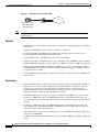
Configuring 1-Port ADSL WAN Interface Card 3-29
Benefits 3-30
Restrictions 3-30
Prerequisites 3-31
Configuration Tasks 3-31
Configuring the ADSL Port on the ADSL WAN Interface Card
Verifying ATM Configuration 3-32
Configuration Examples 3-34
Configuring the NM-AIC-64, Contact Closure Network Module
3-31
3-34
Software Configuration Guide For Cisco 2600 Series, Cisco 3600 Series, and Cisco 3700 Series Routers
OL-1957-03
v
Contents
Serial Communication Channels 3-35
Serial Data Channel 3-36
Asynchronous Craft Port 3-36
Configuring the AIC 3-36
Configuration Tasks 3-37
Configuring the AIC 3-38
Accessing the AIC 3-40
Configuring the NOC IP Address 3-40
Configuring Alarms 3-41
Programming the Analog Contact Points 3-41
Programming the Discrete Contact Points 3-43
Verifying the IP Address 3-43
Troubleshooting Tips 3-45
Monitoring and Maintaining the NM-AIC-64 Contact Closure Network Module
Software Upgrade 3-45
Configuration Backup 3-46
Override 3-46
Configuration Examples 3-46
3-45
Configuring the 1-Port HSSI Network Module 3-46
Configuration Tasks 3-47
Specify a HSSI 3-47
Specify HSSI Encapsulation 3-47
Invoke ATM on a HSSI Line 3-48
Convert HSSI to Clock Master 3-48
Disable Fair Queueing 3-48
Configuration Examples 3-48
Configuring the Compression Network Module for the
Cisco 3600 Series Routers 3-49
Configuration Task 3-49
Configuration Example 3-50
Configuring the Digital Modem Network Module for the
Cisco 3640 Router 3-50
Prerequisites 3-51
Configuration Tasks 3-51
Configure the E1/T1 Network Module for ISDN PRI 3-52
Configure Channelized E1 ISDN PRI 3-52
Configure Channelized T1 ISDN PRI 3-53
Configure the ISDN D-Channel Serial Interfaces 3-53
Configure the ISDN D-Channel Serial Interface for E1 Modules
Configure the ISDN D-Channel Serial Interface for T1 Modules
3-54
3-54
Software Configuration Guide For Cisco 2600 Series, Cisco 3600 Series, and Cisco 3700 Series Routers
vi
OL-1957-03
Contents
Configure the Loopback Interface 3-55
Configure the LAN Interface 3-55
Create the Group Asynchronous Interface 3-55
Configure the ISDN Dialer Interface 3-56
Configure the Default IP Pool Information 3-57
Configure Modem Lines for Dial-In and Dial-Out 3-57
Configure the Modem for Dial-In 3-58
Configure the Modem for Dial-Out 3-58
Configuration Example 3-58
Configuring 1-Port G.SHDSL WAN Interface Card 3-58
Restrictions 3-60
Prerequisites 3-60
Configuration Tasks 3-60
Configuring G.SHDSL on a Cisco Router 3-60
Configuring ILMI on the DSLAM Connected to the ADSL WAN
Verifying ATM Configuration 3-62
Configuration Examples 3-64
Saving Configuration Changes
Where to Go Next
CHAPTER
4
3-62
3-65
3-65
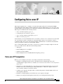
Configuring Voice-over-IP 4-1
Voice-over-IP Prerequisites
4-1
Configuring the Voice Interface
4-2
Voice-over-IP Configuration Examples 4-3
FXS-to-FXS Connection Using RSVP 4-4
Configuration for Router RLB-1 4-4
Configuration for Router RLB-w 4-5
Configuration for Router R12-e 4-5
Configuration for Router RLB-2 4-6
Linking PBX Users with E&M Trunk Lines 4-6
Router SJ Configuration 4-7
Router SLC Configuration 4-8
PSTN Gateway Access Using FXO Connection 4-8
Router SJ Configuration 4-9
Router SLC Configuration 4-9
PSTN Gateway Access Using FXO Connection (PLAR Mode)
Router SJ Configuration 4-10
Router SLC Configuration 4-11
Configuring Direct-Inward Dialing on a BRI Port 4-11
4-10
Software Configuration Guide For Cisco 2600 Series, Cisco 3600 Series, and Cisco 3700 Series Routers
OL-1957-03
vii
Contents
Router 1 Configuration
Router 2 Configuration
Router 3 Configuration
Where to Go Next
APPENDIX
A
4-12
4-12
4-12
4-12
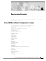
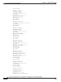
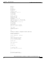
Configuration Examples
A-1
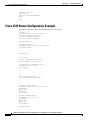
Cisco 2600 Series Router Configuration Example
Cisco 3631 Router Configuration Example
A-6
Cisco 3725 Router Configuration Example
A-10
A-1
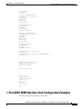
1-Port ADSL WAN Interface Card Configuration Examples A-11
VoATM over AAL2 on the ATM Interface Configuration Example
VoATM over AAL5 on the ATM Interface Configuration Example
A-12
A-14
NM-AIC-64, Contact Closure NetworkConfiguration Examples A-16
AIC IP Address Configuration Example A-16
IP Route to the AIC Configuration Examples A-20
With an Unnumbered IP Address A-20
Without an Unnumbered IP Address A-21
AIC CLI Configuration for Alarms A-22
Discrete Alarm A-22
Analog Alarm Monitoring Current A-22
Analog Alarm Monitoring Current Configured as a Discrete A-22
Cisco 3640 Central Site Configuration to Support ISDN and Modem Calls
Configuration in CPE Mode Example A-25
Configuration in CO Mode Example A-27
APPENDIX
B
Formatting the Compact Flash Memory Cards
A-23
B-1
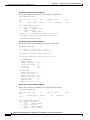
Formatting Procedures for Compact Flash Memory Cards B-1
Formatting Procedures B-1
Determining the File System on a Compact Flash Memory Card B-1
Formatting Compact Flash Memory as a Class B Flash File System B-3
Formatting Compact Flash Memory as a Class C File System B-4
File and Directory Operations B-4
Operations for Use With Class B Flash File System B-4
Operations for Use with Class C Flash File System B-7
File Operations for Class C Flash File System B-7
Directory Operations for Class C Flash File System B-10
B-12
Software Configuration Guide For Cisco 2600 Series, Cisco 3600 Series, and Cisco 3700 Series Routers
viii
OL-1957-03
Contents
APPENDIX
C
Using the ROM Monitor
C-1
Entering the ROM Monitor Mode C-1
Configure C-1
Verify C-1
ROM Monitor Commands C-2
ROM Monitor Syntax Conventions C-2
Command Descriptions C-3
Debugging Commands C-5
Configuration Register Commands C-5
Using the show rom-monitor command C-6
Using the upgrade rom-monitor Command C-7
Procedures for Recovering Boot and System Images
Using the xmodem Command C-8
Using the tftpdnld Command C-8
C-8
INDEX
Software Configuration Guide For Cisco 2600 Series, Cisco 3600 Series, and Cisco 3700 Series Routers
OL-1957-03
ix
Contents
Software Configuration Guide For Cisco 2600 Series, Cisco 3600 Series, and Cisco 3700 Series Routers
x
OL-1957-03
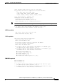
Preface
This preface discusses the objectives, audience, organization, and conventions of this software
configuration guide, and where to get the latest version of this guide.
Objectives
After installing the router, use this guide to complete a basic router configuration using the setup
command facility. It also contains information on using the Cisco IOS software to perform other
configuration tasks, such as configuring a Voice-over-IP interface and other features.
This guide does not provide complete configuration instructions. Refer to the Cisco IOS configuration
guides and command references for detailed configuration instructions. These publications are available
on the Documentation CD-ROM that came with your router and on Cisco.com. See the “Obtaining
Documentation” section on page xvi for more information.
Audience
This publication is designed for the person who will be responsible for configuring your router. This
guide is intended primarily for the following audiences:
•
Customers with technical networking background and experience
•
System administrators who are familiar with the fundamentals of router-based internetworking, but
who might not be familiar with Cisco IOS software
•
System administrators who are responsible for installing and configuring internetworking
equipment, and who are familiar with Cisco IOS software
Software Configuration Guide for Cisco 2600 Series, Cisco 3600 Series, and Cisco 3700 Series Routers
OL-1957-03
xi
Preface
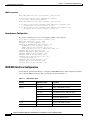
Organization
Organization
The major sections of this software configuration guide include:
Chapter
Title
Description
Chapter 1
Understanding Interface
Numbering and Cisco IOS
Software Basics
Provides an overview of the interface numbering
conventions for the Cisco routers. Also provides a basic
understanding of the Cisco IOS software.
Chapter 2
Using the Setup Command Describes how to use the setup command facility to
Facility
configure your router.
Chapter 3
Configuring with the
Command-Line Interface
Describes how to use the Cisco IOS software
command-line interface (CLI) to configure basic router
functionality.
Chapter 4
Configuring Voice-over-IP
Describes how to configure voice network modules
with recEive and transMit (E&M), Foreign Exchange
Office (FXO), and Foreign Exchange Station (FXS)
interfaces for your router.
Appendix A
Configuration Examples
Provides configuration examples of the Cisco 2600
series, Cisco 3600 series, and Cisco 3700 series routers.
Appendix B
Appendix B, “Formatting
Provides configuration information for the Cisco Flash
the Compact Flash Memory memory.
Cards”
Appendix C
Appendix C, “Using the
ROM Monitor”
Describer how the ROM Monitor works in the Cisco
2600 series, Cisco 3600 series, and Cisco 3700 series
routers.
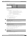
Document Conventions
This publication uses the following conventions to convey instructions and information:
Convention
Description
boldface font
Commands and keywords.
italic font
Variables for which you supply values.
[
Keywords or arguments that appear within square brackets are optional.
]
{x | y | z}
A choice of required keywords appears in braces separated by vertical bars.
You must select one.
screen font
Examples of information displayed on the screen.
boldface
screen font
Examples of information you must enter.
<
>
Nonprinting characters, for example passwords, appear in angle brackets in
contexts where italic font is not available.
[
]
Default responses to system prompts appear in square brackets.
Software Configuration Guide for Cisco 2600 Series, Cisco 3600 Series, and Cisco 3700 Series Routers
xii
OL-1957-03
Preface
Additional Information
Note
Timesaver
Caution
Tip
This symbol means reader take note. Notes contain helpful suggestions or references to additional
information and material.
This symbol means the described action saves time. You can save time by performing the action
described in the paragraph.
This symbol means reader be careful. In this situation, you might do something that could result in
equipment damage or loss of data.
This symbol means the following information will help you solve a problem. The tips information
might not be troubleshooting or even an action, but could be useful information, similar to a
Timesaver.
Additional Information
This guide does not contain the following:
•
Network design information
•
Application case studies
•
Troubleshooting information
•
A comprehensive reference to access services
For l information about any of the above topics, refer to the following resources:
•
Cisco.com
•
Documentation CD-ROM
•
Cisco Technical Assistance Center (TAC)
Related and Referenced Documents
The documents described here are available online and on the documentation CD-ROM that you received
with your router. To be sure of obtaining the latest information, you should access the online
documentation.
To print a document in its original page format, access the online document, and click on the PDF icon.
You can also order printed copies of documents. See the Ordering Documentation.
Software Configuration Guide for Cisco 2600 Series, Cisco 3600 Series, and Cisco 3700 Series Routers
OL-1957-03
xiii
Preface
Related and Referenced Documents
To Access Online User Documentation (PDF and HTML Formats):
From Cisco.com at http://www.cisco.com, under Service & Support, select Technical Documents and
select Cisco Product Documentation.
Access User Documentation on the Documentation CD-ROM (HTML format only):
On the Documentation CD-ROM, select Cisco Product Documentation.
Paths to specific documents are provided below, starting at Cisco Product Documentation.
Tip
To navigate up to the next higher level in the documentation hierarchy, click on CONTENTS in the
navigation bar at the top of each page.
Table 1
Related and Referenced Documents
Cisco Product
Cisco 2600 series routers
Cisco 3600 series routers
Document Title
•
Cisco 2600 Series Routers Hardware
Installation Guide
•
Cisco 2600 Series Modular Routers Quick
Access Guide
•
Cisco Network Modules Hardware
Installation Guide
•
Cisco WAN Interface Cards Hardware
Installation Guide
•
Regulatory Compliance and Safety
Information
•
Cisco 3600 Series Routers Hardware
Installation Guide
•
Cisco 3620 and Cisco 3640 Modular Access
Routers Quick Start Guide
•
Cisco 3660 Modular Access Router Quick
Start Guide
•
Cisco Network Modules Hardware
Installation Guide
•
Cisco WAN Interface Cards Hardware
Installation Guide
•
Cisco RPS Hardware Installation Guide
•
Regulatory Compliance and Safety
Information
Software Configuration Guide for Cisco 2600 Series, Cisco 3600 Series, and Cisco 3700 Series Routers
xiv
OL-1957-03
Preface
Related and Referenced Documents
Table 1
Related and Referenced Documents (continued)
Cisco Product
Cisco 3700 series routers
Cisco IOS software
Note
Refer to the modular reference
publication that corresponds to the
Cisco IOS software release installed on
your server.
Document Title
•
Cisco 3700 Series Routers Hardware
Installation Guide
•
Cisco 3725 and Cisco 3745 Modular Access
Routers Quick Start Guide
•
Cisco Network Modules Hardware
Installation Guide
•
Cisco WAN Interface Cards Hardware
Installation Guide
•
Regulatory Compliance and Safety
Information
•
Cisco IOS Configuration Fundamentals
Configuration Guide
•
Cisco IOS Configuration Fundamentals
Command Reference
•
Cisco IOS Dial Technologies Configuration
Guide
•
Cisco IOS Wide-Area Networking
Configuration Guide
•
Cisco IOS IP Configuration Guide
Release 12.2
•
Cisco IOS Wide-Area Networking Command
Reference
•
Debug Command Reference
•
System Error Messages
•
Cisco IOS Software Command Summary
•
Cisco IOS Release notes for your release
Software Configuration Guide for Cisco 2600 Series, Cisco 3600 Series, and Cisco 3700 Series Routers
OL-1957-03
xv
Preface
Obtaining Documentation
Table 1
Related and Referenced Documents (continued)
Cisco Product
Other documents
Document Title
•
Information about TL1 commands can be
found in the Telcordia Technology (formerly
Bellcore) document Network Maintenance:
Network Element and Transport Surveillance
Messages, GR-833-CORE, Issue 5,
November 1996. For a reference of
security-related commands (ACT-USER and
CANC-USER) refer to Telcordia
Technology’s Operations Applications
Messages-Network Element and Network
System Security Admin Messages,
TR-NWT-000835, Issue 2, January 1993.
•
Information about the PRI network module,
refer to the 1-Port and 2-Port ISDN-PRI
Network Module Configuration Note. For
information on how to install an Ethernet
module, refer to the 1-Port Ethernet Network
Module Configuration Note or the 4-Port
Ethernet Network Module Configuration
Note.
•
For information on how to correctly install
and configure the Digital Network module
and the PRI module, refer to the Digital
Modem Network Module Configuration Note.
•
To configure the router for voice traffic, refer
to the Voice over IP Configuration document
•
To configure DLAMs, refer to the
Configuration Guide for DSLAs with NI-2.
Obtaining Documentation
The following sections provide sources for obtaining documentation from Cisco Systems.
World Wide Web
You can access the most current Cisco documentation on the World Wide Web at the following sites:
•
http://www.cisco.com
•
http://www-china.cisco.com
•
http://www-europe.cisco.com
Software Configuration Guide for Cisco 2600 Series, Cisco 3600 Series, and Cisco 3700 Series Routers
xvi
OL-1957-03
Preface
Obtaining Technical Assistance
Documentation CD-ROM
Cisco documentation and additional literature are available in a CD-ROM package, which ships
with your product. The Documentation CD-ROM is updated monthly and may be more current than
printed documentation. The CD-ROM package is available as a single unit or as an annual subscription.
Ordering Documentation
Cisco documentation is available in the following ways:
•
Registered Cisco Direct Customers can order Cisco Product documentation from the Networking
Products MarketPlace:
http://www.cisco.com/cgi-bin/order/order_root.pl
•
Registered Cisco.com users can order the Documentation CD-ROM through the online Subscription
Store:
http://www.cisco.com/go/subscription
•
Nonregistered Cisco.com users can order documentation through a local account representative by
calling Cisco corporate headquarters (California, USA) at 408 526-7208 or, in North America, by
calling 800 553-NETS(6387).
Documentation Feedback
If you are reading Cisco product documentation on the World Wide Web, you can submit technical
comments electronically. Click Feedback in the toolbar and select Documentation. After you complete
the form, click Submit to send it to Cisco.
You can e-mail your comments to [email protected].
To submit your comments by mail, for your convenience many documents contain a response card
behind the front cover. Otherwise, you can mail your comments to the following address:
Cisco Systems, Inc.
Document Resource Connection
170 West Tasman Drive
San Jose, CA 95134-9883
We appreciate your comments.
Obtaining Technical Assistance
Cisco provides Cisco.com as a starting point for all technical assistance. Customers and partners can
obtain documentation, troubleshooting tips, and sample configurations from online tools. For Cisco.com
registered users, additional troubleshooting tools are available from the TAC website.
Software Configuration Guide for Cisco 2600 Series, Cisco 3600 Series, and Cisco 3700 Series Routers
OL-1957-03
xvii
Preface
Obtaining Technical Assistance
Cisco.com
Cisco.com is the foundation of a suite of interactive, networked services that provides immediate, open
access to Cisco information and resources at anytime, from anywhere in the world. This highly
integrated Internet application is a powerful, easy-to-use tool for doing business with Cisco.
Cisco.com provides a broad range of features and services to help customers and partners streamline
business processes and improve productivity. Through Cisco.com, you can find information about Cisco
and our networking solutions, services, and programs. In addition, you can resolve technical issues with
online technical support, download and test software packages, and order Cisco learning materials and
merchandise. Valuable online skill assessment, training, and certification programs are also available.
Customers and partners can self-register on Cisco.com to obtain additional personalized information and
services. Registered users can order products, check on the status of an order, access technical support,
and view benefits specific to their relationships with Cisco.
To access Cisco.com, go to the following website:
http://www.cisco.com
Technical Assistance Center
The Cisco TAC website is available to all customers who need technical assistance with a Cisco product
or technology that is under warranty or covered by a maintenance contract.
Contacting TAC by Using the Cisco TAC Website
If you have a priority level 3 (P3) or priority level 4 (P4) problem, contact TAC by going to the TAC
website:
http://www.cisco.com/tac
P3 and P4 level problems are defined as follows:
•
P3—Your network performance is degraded. Network functionality is noticeably impaired, but most
business operations continue.
•
P4—You need information or assistance on Cisco product capabilities, product installation, or basic
product configuration.
In each of the above cases, use the Cisco TAC website to quickly find answers to your questions.
To register for Cisco.com, go to the following website:
http://www.cisco.com/register/
If you cannot resolve your technical issue by using the TAC online resources, Cisco.com registered users
can open a case online by using the TAC Case Open tool at the following website:
http://www.cisco.com/tac/caseopen
Contacting TAC by Telephone
If you have a priority level 1(P1) or priority level 2 (P2) problem, contact TAC by telephone and
immediately open a case. To obtain a directory of toll-free numbers for your country, go to the following
website:
http://www.cisco.com/warp/public/687/Directory/DirTAC.shtml
Software Configuration Guide for Cisco 2600 Series, Cisco 3600 Series, and Cisco 3700 Series Routers
xviii
OL-1957-03
Preface
Obtaining Technical Assistance
P1 and P2 level problems are defined as follows:
•
P1—Your production network is down, causing a critical impact to business operations if service is
not restored quickly. No workaround is available.
•
P2—Your production network is severely degraded, affecting significant aspects of your business
operations. No workaround is available.
Software Configuration Guide for Cisco 2600 Series, Cisco 3600 Series, and Cisco 3700 Series Routers
OL-1957-03
xix
Preface
Obtaining Technical Assistance
Software Configuration Guide for Cisco 2600 Series, Cisco 3600 Series, and Cisco 3700 Series Routers
xx
OL-1957-03
C H A P T E R
1
Understanding Interface Numbering and
Cisco IOS Software Basics
This chapter provides an overview of the interface numbering in the Cisco 2600 series, Cisco 3600
series, and Cisco 3700 series routers. It also describes how to use the Cisco IOS software commands.
Understanding Interface Numbering
This section contains information with which you should be familiar before you begin to configure your
router for the first time, including interface numbering and what you should do before starting your
router.
Cisco 2600 Series Interface Numbering
Each network interface on a Cisco 2600 series router is identified by a slot number and a unit number.
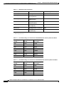
Table 1-1 lists the router models and summarizes the interfaces supported on each model that are
available in the Cisco 2600 series routers.
Table 1-1
Summary of Cisco 2600 Series Router Models and Interfaces
Model
Ethernet
(10BASE-T)
Cisco 2610
1
Fast
Token-Ring Ethernet
(RJ-45)
(10/100)
Network
Module Slot
WAN
Interface
Card Slots
Advanced
Integration
Module Slots
1
2
1
1
2
1
1
2
1
1
2
1
1
1
2
1
1
1
2
1
Cisco 2610XM
Cisco 2611
1
2
Cisco 2611XM
Cisco 2612
Cisco 2613
2
1
Cisco 2620
1
1
2
1
Cisco 2620XM
1
1
2
1
Cisco 2621
2
1
2
1
Cisco 2621XM
2
1
2
1
Cisco 2650
1
1
2
1
Software Configuration Guide For Cisco 2600 Series, Cisco 3600 Series, and Cisco 3700 Series Routers
OL-1957-03
1-1
Chapter 1
Understanding Interface Numbering and Cisco IOS Software Basics
Understanding Interface Numbering
Table 1-1
Summary of Cisco 2600 Series Router Models and Interfaces (continued)
Model
Note
Ethernet
(10BASE-T)
Fast
Token-Ring Ethernet
(RJ-45)
(10/100)
Network
Module Slot
WAN
Interface
Card Slots
Advanced
Integration
Module Slots
Cisco 2650XM
1
1
2
1
Cisco 2651
2
1
2
1
Cisco 2651XM
2
1
2
1
Cisco 2691
2
1
3
2
The number and type of interfaces vary depending on the router.
WAN and LAN Interface Numbering
The Cisco 2600 series router chassis contains the following wide-area network (WAN) and local-area
network (LAN) interface types:
•
Built-in LAN interfaces: Ethernet, FastEthernet, Token Ring
•
Two or three slots in which you can install WAN interface cards (WICs)
•
One slot in which you can install a network module
The numbering format is Interface-type Slot-number/Interface-number. Two examples are:
Ethernet 0/0
Serial 1/2
The slot number is 0 for all built-in interfaces and 0 for all WIC interfaces; the slot number is 1 for
network module interfaces.
Interface (port) numbers begin at 0 for each interface type, and continue from right to left and (if
necessary) from bottom to top.
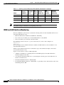
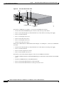
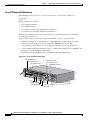
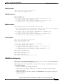
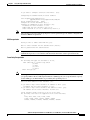
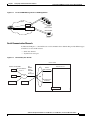
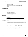
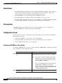
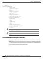
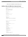
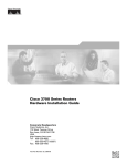
Figure 1-1 below shows a router of 1 RU height with:
•
A WIC in each WIC slot (containing interface Serial 0/0 in physical slot W0, and interface
Serial 0/1 in physical slot W1)
•
A 4-serial-port network module in slot 1 (containing the following ports: Serial 1/0, Serial 1/1,
Serial 1/2, and Serial 1/3)
•
First built-in Ethernet interface—Ethernet 0/0
•
Second built-in Ethernet interface—Ethernet 0/1, or optionally in Cisco 2612 and Cisco 2613 only:
Token Ring interface 0/0
Software Configuration Guide For Cisco 2600 Series, Cisco 3600 Series, and Cisco 3700 Series Routers
1-2
OL-1957-03
Chapter 1
Understanding Interface Numbering and Cisco IOS Software Basics
Understanding Interface Numbering
Figure 1-1
Example of 1RU Router
Serial 0/1 Serial 0/0
3
CN/LP
RXC
RXD
TXC
TXD
2
CN/LP
RXC
RXD
TXC
TXD
1
CN/LP
RXC
RXD
CONN
TXC
W1
TXD
0
CN/LP
RXC
RXD
TXC
TXD
EN
SERIAL
W0
CONN
Cisco 26
12
SERIAL
W0
LINK TOK
EN RIN
G 0/0 ACT
W0
LINK ETH
ERNET
0/0
ACT CON
SOLE
100-24
0V– 1A
50/60 Hz
47 W
28308
SERIAL
A/S
AUX
Serial 1/3 Serial 1/1
Ethernet Auxiliary
0/0
port
Ethernet 0/1
Console
port
Serial 1/2 Serial 1/0
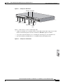
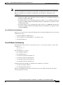
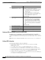
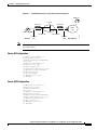
Figure 1-2 below shows a router of 2 RU height with:
•
A WIC in each WIC slot (containing interfaces Serial 0/0 and Serial 0/1 in physical slot W0,
interface Serial 0/2 in physical slot W1, and interface BRI 0/0 in physical slot W2)
•
A 2-port T1 network module in slot 1 (containing the following ports: T1 1/0 and T1 1/1)
•
Two built-in Ethernet 10/100 interfaces—FastEthernet 0/0 and FastEthernet 0/1
Figure 1-2
Example of a 2RU Router
NM-HDV
BANK 4
BA
Software Configuration Guide For Cisco 2600 Series, Cisco 3600 Series, and Cisco 3700 Series Routers
OL-1957-03
1-3
Chapter 1
Understanding Interface Numbering and Cisco IOS Software Basics
Understanding Interface Numbering
Note
The slot number for all WIC interfaces is always 0. (The W0 and W1 slot designations are for
physical slot identification only.) Interfaces in the WICs are numbered from right to left, starting with
0/0 for each interface type, regardless of which physical slot the WICs are installed in. Some
examples are:
– If physical slot W0 is empty and physical slot W1 contains a 1-port serial WIC, the interface
number in the WIC is numbered Serial 0/0.
– If slot W0 contains a 2-port serial WIC and slot W1 contains a 1-port serial WIC, the interfaces
in physical slot W0 are numbered Serial 0/0 and Serial 0/1, and the interface in physical slot W1
is numbered Serial 0/2.
– If slot W0 contains a 2-port serial WIC and slot W1 contains a 1-port BRI WIC, the interfaces
in physical slot W0 are numbered Serial 0/0 and Serial 0/1, and the interface in physical slot W1
is numbered BRI 0/0.
Voice Interface Numbering in Cisco 2600 Series Routers
Voice interfaces are numbered differently from the WAN interfaces described in the previous section.
Voice interfaces are numbered as follows:
chassis slot/voice module slot/voice interface
If a 4-channel voice network module is installed in chassis slot 1, the voice interfaces are:
•
1/0/0—Chassis slot 1/Voice module slot 0/Voice interface 0
•
1/0/1—Chassis slot 1/Voice module slot 0/Voice interface 1
•
1/1/0—Chassis slot 1/Voice module slot 1/Voice interface 0
•
1/1/1—Chassis slot 1/Voice module slot 1/Voice interface 1
Cisco 3600 Series Interface Numbering
Each individual network interface on a Cisco 3600 series router is identified by a slot number and a unit
number.
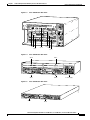
Cisco 3600 Series Router Slot Numbering
A Cisco 3600 series router chassis includes up to six slots in which you can install modules. The
Cisco 3600 series includes the Cisco 3660 (see Figure 1-3), Cisco 3640 (see Figure 1-4) and Cisco 3620
routers (see Figure 1-5). The Cisco 3660 has six network module slots, the Cisco 3640 has four slots,
the Cisco 3620 has two slots, and the Cisco 3631 (see Figure 1-6) has four slots. You can install any
module into any available slot in the chassis.
Software Configuration Guide For Cisco 2600 Series, Cisco 3600 Series, and Cisco 3700 Series Routers
1-4
OL-1957-03
Chapter 1
Understanding Interface Numbering and Cisco IOS Software Basics
Understanding Interface Numbering
Figure 1-3
Cisco 3660 Router Rear View
VCC OK
SYSTEM
FDX
LINK
100Mbps
FDX
LINK
100Mbps
1
0
18030
HIGH SPEED SERIAL
1HSSI
SEE MANUAL BEFORE INSTALLATION 0
V0
H
TC
EN
TD
LB/CN
1
RC
V1
RD
VIC
FXS
IN USE
IN USE
VOICE
2V
SERIAL
4T
ETHERNET
4E
SERIAL 3
SERIAL 2
SERIAL 1
SERIAL 0
ETH 3
ETH 2
ETH 1
3 2 1
CN/LP RXC
TXC
TXD
CN/LP RXC
RXD
TXC
TXD
CN/LP RXC
EN
RXD
Slot 6
Slot 4
Slot 2
Figure 1-4
ETH 0
0
LINK
RXD
TXC
TXD
CN/LP RXC
RXD
TXC
ACT
TXD
Slot 5
Slot 3
Slot 1
Slot 0
Cisco 3640 Router Rear View
Slot 2
Slot 3
2
BRI
NT1
WO 2E W1
DO NOT INSTALL WAN INTERFACE
CARDS WITH POWER APPLIED
2W
SERIAL
ACT
STP
ETHERNET 1
LNK
AUI
EN
ETHERNET 0
LNK
LNK
ACT
SERIAL
ETHERNET 1
ACT
1
LNK
ACT
SEE MANUAL BEFORE INSTALLATION
H6551
B2
ACT
B1
ACT
2E
W1
2W
NT1
3
AUI
EN
ETHERNET 0
INPUT 100-240VAC 50/60HZ 3.0-1.5 AMPS
Slot 1
Power supply
Cisco 3620 Router Rear View
H7238
Figure 1-5
Slot 0
2W
DO NOT INSTALL WAN INTERFACE
CARDS WITH POWER APPLIED
ETHERNET 0
ETHERNET
ETH 1 1
Slot 1
ACT
ACT
AUI
EN
LNK
SERIAL
LNK
ACT
LNK
ACT
1
ETHERNET 1
WO 2E W1
SERIAL
INSTALLATION
ACT
BRI
NT1
B2
SEE MANUAL BEFORE
LNK
B1
ACT
NT1
2E
W1
2W
AUI
EN
0
ETHERNET 0
Slot 0
Software Configuration Guide For Cisco 2600 Series, Cisco 3600 Series, and Cisco 3700 Series Routers
OL-1957-03
1-5
Chapter 1
Understanding Interface Numbering and Cisco IOS Software Basics
Understanding Interface Numbering
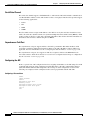
Figure 1-6
Cisco 3631 Router Rear View
Slot 2
W1
W0
AIC-64
CONN
1
CONN
2
ASYNC
CONN
3
CONN
4
STAT
31
30
27
29
26
28
25
ASYNC
EN
24-31
24
23
15
14
11
13
10
12
9
ASYNC
22
19
21
18
20
17
ASYNC
16-23
16
8-15
8
ASYNC
0-7
CD
1
TD
2
4
RD
3
5
LP
6
AL
7
0
EN
SEE MANU
AL BEFO
RE INSTA
LLATION
DSU
56K
SEE MANU
AL BEFO
RE INSTA
LLATION
FastEthernet 0/0
Console/AUX
ports
68501
Slot 1
For the Cisco 3660 router (see Figure 1-3), the slots are numbered as follows:
•
Slot 0 contains fixed FastEthernet ports and is located at the top of the chassis.
•
Slot 1 is at the bottom right (as viewed from the rear of the chassis), near the power supply.
•
Slot 2 is at the bottom left.
•
Slot 3 is at the right, above slot 1.
•
Slot 4 is at the left, above slot 2
•
Slot 5 is at the right, above slot 3.
•
Slot 6 is at the left, above slot 4.
For the Cisco 3620 and Cisco 3640 routers shown in Figure 1-4 and Figure 1-5, the slots are numbered
as follows:
•
Slot 0 is at the bottom right (as viewed from the rear of the chassis), near the power supply.
•
Slot 1 is at the bottom left.
•
Slot 2 is at the top right, above slot 0.
•
Slot 3 is at the top left, above slot 1.
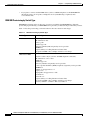
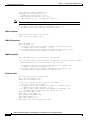
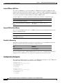
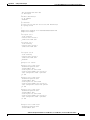
For the Cisco 3631 router shown in Figure 1-6, the slots are numbered as follows:
•
Slot 0 for all built-in interfaces like the FastEthernet port at the bottom center near the Console/AUX
ports
•
Slot 0 for all WAN interface card (WIC) interfaces
•
Slot 1 for network module interfaces at the bottom left.
•
Slot 2 for network module interfaces at the top left, above slot 1.
Software Configuration Guide For Cisco 2600 Series, Cisco 3600 Series, and Cisco 3700 Series Routers
1-6
OL-1957-03
Chapter 1
Understanding Interface Numbering and Cisco IOS Software Basics
Understanding Interface Numbering
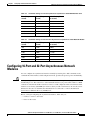
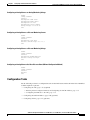
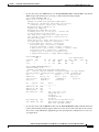
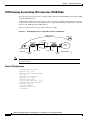
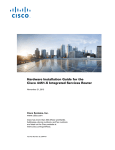
Figure 1-7
Example of the Cisco 3631 Router Interface Numbering
Internal connections to serial 2/0
Serial 0/0
Serial 0/2
Serial 0/1
AIC-64
CONN
1
CONN
2
ASYNC
CONN
3
CONN
4
STAT
31
30
27
29
26
28
25
ASYNC
24-31
ASYNC
8-15
EN
24
23
14
11
13
10
12
9
22
19
21
18
20
17
ASYNC
16-23
16
62052
15
8
ASYNC
0-7
CD
1
TD
2
4
RD
3
5
LP
6
AL
7
0
EN
SEE MANU
AL BEFO
RE INSTA
LLATION
DSU
56K
SEE MANU
AL BEFO
RE INSTA
LLATION
FastEthernet 0/0
Serial 1/0 to 1/7
Console/AUX
Serial 1/16 to 1/23
ports
Serial 1/8 to 1/15
Serial 1/24 to 1/31
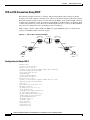
Figure 1-7 shows an example of the interface numbering where the following interfaces are installed:
Note
•
A WIC in each WIC slot (containing interfaces serial 0/0 and serial 0/1 in physical slot W0, and
interface serial 0/2 in physical slot W1)
•
A 32-port asynchronous network module in slot 1 (containing interfaces serial 1/0 through serial
1/31)
•
An alarm interface controller network module in slot 2 (internally connected to interface serial 2/0)
•
One built-in Ethernet 10/100 interface—FastEthernet 0/0
The logical slot number for all WIC interfaces is always 0. (The W0 and W1 slot designations are for
physical slot identification only.) Interfaces in the WICs are numbered from right to left, starting with
0/0 for each interface type, regardless of which physical slot the WICs are installed in. Some
examples are:
– If physical slot W0 is empty and physical slot W1 contains a 1-port serial WIC, then the logical
interface in the WIC is numbered serial 0/0.
– If physical slot W0 contains a 2-port serial WIC and slot W1 contains a 1-port serial WIC, then
the logical interfaces in physical slot W0 are numbered serial 0/0 and serial 0/1 and the logical
interface in physical slot W1 is numbered Serial 0/2.
– If physical slot W0 contains a 2-port serial WIC and slot W1 contains a 1-port BRI WIC, then
the logical interfaces in physical slot W0 are numbered serial 0/0 and serial 0/1, and the logical
interface in physical slot W1 is numbered BRI 0/0.
Software Configuration Guide For Cisco 2600 Series, Cisco 3600 Series, and Cisco 3700 Series Routers
OL-1957-03
1-7
Chapter 1
Understanding Interface Numbering and Cisco IOS Software Basics
Understanding Interface Numbering
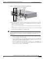
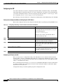
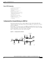
Some modules have two small slots, labeled W0 and W1, for WAN interface cards. For example,
Figure 1-8 shows the W0 and W1 slots of the 2 Ethernet 2 WAN card slot (2E 2-slot) module. You can
install WAN interface cards into the small module slots (W0 and W1). Integrated Services Digital
Network (ISDN) Basic Rate Interface (BRI) WAN interface cards are keyed so that you can install them
into slot W1 only. Serial WAN interface cards can be installed into either slot, W0 or W1.
WAN Interface Card Slots
ETHERNET 1
Slot W0
WO
AUI
EN
LNK
ACT
ACT
STP
ILNK
Slot W1
2E
2W W1
ETHERNET 0
H8603
Figure 1-8
Cisco 3600 Series Router Unit Numbering
Cisco 3600 series routers unit numbers identify the interfaces on the modules and WAN interface cards
installed in the router. Unit numbers begin at 0 for each interface type, and continue from right to left
and (if necessary) from bottom to top. Modules and WAN interface cards are identified by interface type,
slot number, followed by a forward slash
(/), and then the unit number; for example, Ethernet 0/0.
Note
In the Cisco 3660 router, the fixed FastEthernet ports are located in chassis slot 0, and are identified
by:
interface type chassis slot/ unit number
For example: FastEthernet 0/0
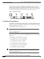
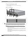
Figure 1-9 shows a router with a 2E 2-slot module in slots 0 and 1. Two serial WAN interface cards are
installed in the module in slot 0. One serial and one ISDN BRI WAN interface card are installed in the
module in slot 1.
As shown in Figure 1-9, the unit numbers are as follows:
Note
•
Slot 0, Ethernet interface 0, referred to as Ethernet 0/0
•
Slot 0, Ethernet interface 1, referred to as Ethernet 0/1
•
Slot 0, serial interface 0, referred to as serial 0/0
•
Slot 0, serial interface 1, referred to as serial 0/1
•
Slot 1, Ethernet interface 0, referred to as Ethernet 1/0
•
Slot 1, Ethernet interface 1, referred to as Ethernet 1/1
•
Slot 1, serial interface 0, referred to as serial 1/0
•
Slot 1, BRI interface 0, referred to as BRI 1/0
The 2E 2-slot module described in this example provides both an attachment unit interface (AUI) and
10BASE-T port. Only one of these ports can be used at a time. The module automatically detects
which port, AUI or 10BASE-T, is in use.
Software Configuration Guide For Cisco 2600 Series, Cisco 3600 Series, and Cisco 3700 Series Routers
1-8
OL-1957-03
Chapter 1
Understanding Interface Numbering and Cisco IOS Software Basics
Understanding Interface Numbering
Cisco 3600 Series Routers Voice Interface Numbering
Voice interfaces are numbered differently from WAN interfaces described in the previous section,
“Cisco 3600 Series Router Unit Numbering.” Voice interfaces are numbered as follows:
interface type chassis slot/voice module slot/voice interface
If you have a 4-channel voice network module installed in slot 1 of your router, the voice interfaces will
be:
•
Slot 1, voice network module slot 0, voice interface 0, referred to as voice 1/0/0 (closest to chassis
slot 0)
•
Slot 1, voice network module slot 0, voice interface 1, referred to as voice 1/0/1
•
Slot 1, voice network module slot 1, voice interface 0, referred to as voice 1/1/0
•
Slot 1, voice network module slot 1, voice interface 1, referred to as voice 1/1/1 (farthest from
chassis slot 0)
Figure 1-9
Cisco 3600 Series Unit Numbers
BRI 1/0
Serial 1/0
Serial 0/1
Serial 0/0
2
WO 2E W1
2W
ACT
BRI
NT1
SERIAL
ETHERNET 1
ETHERNET 0
ETHERNET 1
ACT
LNK
STP
LNK
LNK
ACT
SERIAL
AUI
EN
ACT
1
LNK
ACT
SEE MANUAL BEFORE INSTALLATION
H8604
B2
ACT
B1
ACT
2E
W1
2W
NT1
3
AUI
EN
ETHERNET 0
INPUT 100-240VAC 50/60HZ 3.0-1.5 AMPS
Ethernet 1/1
Ethernet 1/0
Ethernet 0/1
Ethernet 0/0
Power supply
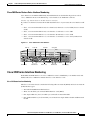
Cisco 3700 Series Interface Numbering
Each WAN and LAN interface on a Cisco 3700 series router is identified by a slot number and a unit
number. The Cisco 3700 series includes the Cisco 3725 and Cisco 3745.
Cisco 3725 Router Interface Numbering
The Cisco 3725 router chassis contains the following wide-area network (WAN) and local area network
(LAN) interface types:
•
Two built-in FastEthernet LAN interfaces
•
Three slots in which you can install WAN interface cards (WICs)
•
One single-width slot (slot 1) in which you can install one network module
•
One double-width slot (slot 2) in which you can install one single-width or double-width network
module
Software Configuration Guide For Cisco 2600 Series, Cisco 3600 Series, and Cisco 3700 Series Routers
OL-1957-03
1-9
Chapter 1
Understanding Interface Numbering and Cisco IOS Software Basics
Understanding Interface Numbering
Cisco 3725 Router Slot Numbering
The numbering format is Interface-type Slot-number/Interface-number. Two examples are:
FastEthernet 0/0
Serial 1/2.
The slot numbers are as follows:
•
0 for all built-in interfaces
•
0 for all WIC interfaces
•
1 for interfaces in the single-width network module slot
•
2 for interfaces in the double-width network module slot
Interface (port) numbers begin at 0 for each interface type, and continue from right to left and (if
necessary) from bottom to top.
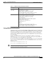
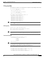
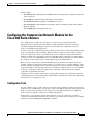
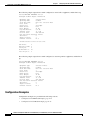
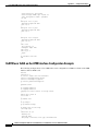
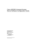
Figure 1-10 below shows an example of interface numbering on a Cisco 3725 router with:
•
A WIC in each WIC slot (containing interfaces Serial 0/0 and Serial 0/1 in physical slot W0,
interface Serial 0/2 in physical slot W1, and interface BRI 0/0 in physical slot W2)
•
A 2-port T1 network module in slot 1 (containing the following ports: T1 1/0 and T1 1/1)
•
A 36-port Etherswitch network module in slot 2 (containing the following ports: FastEthernet 2/0
through 2/35, and GigabitEthernet 2/0 and 2/1)
•
Two built-in Ethernet 10/100 interfaces—FastEthernet 0/0 and FastEthernet 0/1
Figure 1-10 Cisco 3725 Router Rear View
Gigabit Ethernet 2/1
Fast Ethernet 2/35
Fast Ethernet 2/17
Fast Ethernet 2/18
Fast Ethernet 2/0
Gigabit Ethernet 2/0
56482
2
NM-HDV
AL
LP
E1
MANUAL
BEFORE
INSTALLATI
ON
DSU
56K
CD
LLATION
TD
RE INSTA
RD
SEE MANU
AL BEFO
LP
V0
EN
AL
CD
CTRLR
TD
SEE
CD
E2
RD
CTRLR
LP
VWIC
BANK 4
2MFT-E1
BANK 3
BANK 2
BANK 1
BANK 0
AL
1
SEE MANU
AL BEFO
RE INSTA
LLATION
DSU
56K
SEE MANU
AL BEFO
TI 1/1
RE INSTA
LLATION
TI 1/0
Fast Ethernet 0/1
Fast Ethernet 0/0
BRI 0/0
Compact Serial 0/2
Flash slot
Serial 0/1
Serial 0/0
Software Configuration Guide For Cisco 2600 Series, Cisco 3600 Series, and Cisco 3700 Series Routers
1-10
OL-1957-03
Chapter 1
Understanding Interface Numbering and Cisco IOS Software Basics
Understanding Interface Numbering
Note
The slot number for all WIC interfaces is always 0. (The W0 and W1 slot designations are for
physical slot identification only.) Interfaces in the WICs are numbered from right to left, starting with
0/0 for each interface type, regardless of which physical slot the WICs are installed in. Some
examples are:
– If physical slot W0 is empty and physical slot W1 contains a 1-port serial WIC, the interface in
the WIC is numbered Serial 0/0.
– If slot W0 contains a 2-port serial WIC and slot W1 contains a 1-port serial WIC, the interfaces
in physical slot W0 are numbered Serial 0/0 and Serial 0/1, and the interface in physical slot W1
is numbered Serial 0/2.
– If slot W0 contains a 2-port serial WIC and slot W1 contains a 1-port BRI WIC, the interfaces
in physical slot W0 are numbered Serial 0/0 and Serial 0/1, and the interface in physical slot W1
is numbered BRI 0/0.
Cisco 3745 Router Interface Numbering
The Cisco 3745 router chassis contains the following wide-area network (WAN) and local-area network
(LAN) interface types:
•
2 built-in FastEthernet LAN interfaces
•
3 slots in which you can install WAN or voice interface cards
•
4 network module slots.
Cisco 3745 Router Slot Numbering
The numbering format in the Cisco 3745 router is Interface type Slot number/Interface number. Two
examples are:
FastEthernet 0/0
Serial 1/2.
The slot numbers are as follows:
•
0 for all built-in interfaces
•
0 for all WIC interfaces
•
1 for the lower right network module slot
•
2 for the lower left network module slot
•
3 for the upper right network module slot
•
4 for the upper left network module slot
If double-wide network modules are installed, the slot numbers are as follows:
•
2 for the lower double-wide slot
•
4 for the upper double-wide slot
Interface (port) numbers begin at 0 for each interface type, and continue from right to left and (if
necessary) from bottom to top.
Software Configuration Guide For Cisco 2600 Series, Cisco 3600 Series, and Cisco 3700 Series Routers
OL-1957-03
1-11
Chapter 1
Understanding Interface Numbering and Cisco IOS Software Basics
Understanding Interface Numbering
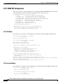
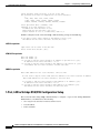
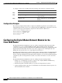
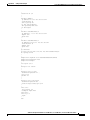
Figure 1-11 shows the rear panel of the Cisco 3745 with:
•
A WIC in each of the three WAN interface card slots
•
A single-width network module in each of the four network module slots
•
Two AC power supplies
Figure 1-11 Cisco 3745 Rear Panel
1
10
SEE MANU
AL BEFO
RE INSTA
LLATI
ON
CD
TD
WIC
2T
RD
CONN
LP
SERIAL
0
SEE MAN
UAL BEFO
RE INST
ALLATION
AL
SERIAL
1
CONN
NM-HDV
NM-HDV
DSU
56K
SERIAL
1
CONN
SERIAL
0
SEE MAN
UAL BEFO
RE INST
ALLATION
BANK
VWIC
4 BAN
2MFT-E1
K 3 BAN
K 2 BAN
K 1 BAN
K0
CONN
WIC
2T
AL
LP
CTRLR
E1
SEE
MANU
AL
BEFORE
INSTA
LLATION
E1
SEE
MANU
AL
BEFORE
INSTA
LLATION
CD
E2
CTRLR
NM-HDV
V0
LP
CTRLR
CD
E2
CTRLR
NM-HDV
BANK
VWIC
4 BAN
2MFT-E1
K 3 BAN
K 2 BAN
K 1 BAN
K0
AL
LP
CTRLR
E1
SEE
MANU
AL
BEFORE
INSTA
LLATION
E1
SEE
MANU
AL
BEFORE
INSTA
LLATION
CD
E2
CTRLR
63390
EN
BANK
VWIC
4 BAN
2MFT-E1
K 3 BAN
K 2 BAN
K 1 BAN
K0
AL
V0
EN
V0
EN
9
8
BANK
VWIC
4 BAN
2MFT-E1
K 3 BAN
K 2 BAN
K 1 BAN
K0
LP
CTRLR
CD
E2
CTRLR
V0
EN
7
6
5
4
Note
AL
3
2
1 Console port
5 Compact Flash slot
2 Auxiliary port
6 Power supplies
3 FastEthernet 0/1
7 Network module slots
4 FastEthernet 0/0
8 WAN or voice interface card slots
The slot number for all WIC interfaces is always 0. (The W0, W1, and W2 slot designations are for
physical slot identification only.) Interfaces in the WICs are numbered from right to left, starting with
0/0 for each interface type, regardless of which physical slot the WICs are installed in. Some
examples are:
– If physical slot W0 is empty and physical slot W1 contains a 1-port serial WIC, the interface in
the WIC is numbered Serial 0/0.
– If slot W0 contains a 2-port serial WIC and slot W1 contains a 1-port serial WIC, the interfaces
in physical slot W0 are numbered Serial 0/0 and Serial 0/1, and the interface in physical slot W1
is numbered Serial 0/2.
– If slot W0 contains a 2-port serial WIC and slot W1 contains a 1-port BRI WIC, the interfaces
in physical slot W0 are numbered Serial 0/0 and Serial 0/1, and the interface in physical slot W1
is numbered BRI 0/0.
Software Configuration Guide For Cisco 2600 Series, Cisco 3600 Series, and Cisco 3700 Series Routers
1-12
OL-1957-03
Chapter 1
Understanding Interface Numbering and Cisco IOS Software Basics
Understanding Cisco IOS Software Basics
Cisco 3700 Series Routers Voice Interface Numbering
Voice interfaces in Cisco 3725 and Cisco 3745 routers are numbered differently from the WAN interfaces
described in the previous section Voice interfaces are numbered as follows:
chassis slot/voice module slot/voice interface
If a 4-channel voice network module is installed in chassis slot 1, the voice interfaces are:
•
1/0/0—Chassis slot 1/Voice module slot 0/Voice interface 0
•
1/0/1—Chassis slot 1/Voice module slot 0/Voice interface 1
•
1/1/0—Chassis slot 1/Voice module slot 1/Voice interface 0
•
1/1/1—Chassis slot 1/Voice module slot 1/Voice interface 1
Understanding Cisco IOS Software Basics
This section describes what you need to know about the Cisco IOS software before you configure the
router using the command-line interface (CLI). This chapter includes the following:
•
Getting Help, page 1-13
•
Understanding Command Modes, page 1-14
•
Undoing a Command or Feature, page 1-15
•
Saving Configuration Changes, page 1-15
•
Where to Go Next, page 1-15
Understanding these concepts will save time as you begin to use the CLI. If you have never used the
Cisco IOS software or need a refresher, take a few minutes to read this chapter before you proceed to the
next chapter.
If you are already familiar with Cisco IOS software, proceed to Chapter 2, “Using the Setup Command
Facility.”
Getting Help
Use the question mark (?) and arrow keys to help you enter commands:
•
For a list of available commands, enter a question mark:
Router> ?
•
To complete a command, enter a few known characters followed by a question mark (with no space):
Router> s?
•
For a list of command variables, enter the command followed by a space and a question mark:
Router> show ?
•
To redisplay a command you previously entered, press the up arrow key. You can continue to press
the up arrow key for more commands.
Software Configuration Guide For Cisco 2600 Series, Cisco 3600 Series, and Cisco 3700 Series Routers
OL-1957-03
1-13
Chapter 1
Understanding Interface Numbering and Cisco IOS Software Basics
Understanding Cisco IOS Software Basics
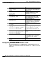
Understanding Command Modes
The Cisco IOS user interface is divided into different modes. Each command mode permits you to
configure different components on your router. The commands available at any given time depend on
which mode you are currently in. Entering a question mark (?) at the prompt displays a list of commands
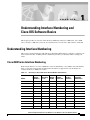
available for each command mode. Table 1-2 lists the most common command modes.
Table 1-2
Timesaver
Common Command Modes
Command Mode
Access Method
Router Prompt
Displayed
User EXEC
Log in.
Router>
Use the logout
command.
Privileged EXEC
From user EXEC mode,
enter the enable
command.
Router#
To exit to user EXEC
mode, use the disable,
exit, or logout
command.
Global configuration
From the privileged
EXEC mode, enter the
configure terminal
command.
Router (config)#
To exit to privileged
EXEC mode, use the
exit or end command,
or press Ctrl-z.
Interface configuration
From the global
configuration mode,
enter the interface type
number command, such
as interface serial 0/0.
Router (config-if)#
To exit to global
configuration mode, use
the exit command.
Exit Method
To exit directly to
privileged EXEC mode,
press Ctrl-z.
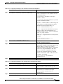
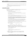
Each command mode restricts you to a subset of commands. If you are having trouble entering a
command, check the prompt, and enter the question mark (?) for a list of available commands. You
might be in the wrong command mode or using the wrong syntax.
In the following example, notice how the prompt changes after each command to indicate a new
command mode:
Router> enable
Password: <enable password>
Router# configure terminal
Router(config)# interface serial 0/0
Router(config-if)# line 0
Router(config-line)# controller t1 0
Router(config-controller)# exit
Router(config)# exit
Router#
%SYS-5-CONFIG_I: Configured from console by console
The last message is normal and does not indicate an error. Press Return to get the Router# prompt.
Software Configuration Guide For Cisco 2600 Series, Cisco 3600 Series, and Cisco 3700 Series Routers
1-14
OL-1957-03
Chapter 1
Understanding Interface Numbering and Cisco IOS Software Basics
Upgrading to a New Cisco IOS Release
Note
You can press Ctrl-z in any mode to immediately return to enable mode (Router#), instead of
entering exit, which returns you to the previous mode.
Undoing a Command or Feature
If you want to undo a command you entered or disable a feature, enter the keyword no before most
commands; for example, no ip routing.
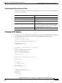
Saving Configuration Changes
You need to enter the copy running-config startup-config command to save your configuration changes
to nonvolatile random-access memory (NVRAM), so the changes are not lost if there is a system reload
or power outage. For example:
Router# copy running-config startup-config
Building configuration...
It might take a minute or two to save the configuration to NVRAM. After the configuration has been
saved, the following appears:
[OK]
Router#
Upgrading to a New Cisco IOS Release
To install or upgrade to a new Cisco IOS release, refer to Appendix B, “Formatting the Compact Flash
Memory Cards.”
Where to Go Next
Now that you have learned some Cisco IOS software basics, you can begin to configure the router using
the CLI.
Remember that:
•
You can use the question mark (?) and arrow keys to help you enter commands.
•
Each command mode restricts you to a set of commands. If you have difficulty entering a command,
check the prompt and then enter the question mark (?) for a list of available commands. You might
be in the wrong command mode or using the wrong syntax.
•
To disable a feature, enter the keyword no before the command; for example, no ip routing.
•
You need to save your configuration changes to NVRAM so the changes are not lost if there is a
system reload or power outage.
Proceed to Chapter 2, “Using the Setup Command Facility,” to begin configuring the router.
Software Configuration Guide For Cisco 2600 Series, Cisco 3600 Series, and Cisco 3700 Series Routers
OL-1957-03
1-15
Chapter 1
Understanding Interface Numbering and Cisco IOS Software Basics
Where to Go Next
Software Configuration Guide For Cisco 2600 Series, Cisco 3600 Series, and Cisco 3700 Series Routers
1-16
OL-1957-03
C H A P T E R
2
Using the Setup Command Facility
This chapter describes how to use the setup command facility to configure your router. The setup
command facility prompts you to enter information needed to start a router functioning quickly. The
facility steps you through a basic configuration, including local-area network (LAN) and wide-area
network (WAN) interfaces. The following sections are included:
•
Before Starting Your Router, page 2-1
•
Using the setup Command Facility, page 2-2
•
Configuring Global Parameters, page 2-2
•
Configuring Interface Parameters, page 2-6
•
Completing the Configuration, page 2-24
•
Where to Go Next, page 2-25
If you prefer to configure the router manually or you wish to configure a module or interface that is not
included in the setup command facility, proceed to “Chapter 3, “Configuring with the Command-Line
Interface,” for step-by-step instructions.
Before Starting Your Router
Before you power on your router and begin to use the setup command facility, make sure you follow
these steps:
Step 1
Set up the hardware as described in the documentation appropriate to your router.
Step 2
Configure your PC terminal emulation program for 9600 baud, 8 data bits, no parity, and 1 stop bit.
Step 3
Determine which network protocols you are supporting (for example, AppleTalk, IP, Novell IPX, and so
on).
Step 4
Determine the following for each network protocol:
•
Addressing plan
•
Which WAN protocols you will run on each interface (for example, Frame Relay, HDLC, X.25, and
so on)
Software Configuration Guide for Cisco 2600 Series, Cisco 3600 Series, and Cisco 3700 Series Routers
OL-1957-03
2-1
Chapter 2
Using the Setup Command Facility
Using the setup Command Facility
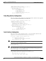
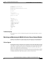
Using the setup Command Facility
The setup command facility displays from your PC terminal emulation program window.
To create a basic configuration for your router, do the following:
Note
•
Complete the steps in the “Configuring Global Parameters” section on page 2-2.
•
Complete the steps in the “Configuring Interface Parameters” section on page 2-6 that apply to your
router and network.
•
Complete the steps in the “Completing the Configuration” section on page 2-24.
If you make a mistake while using the setup command facility, you can exit and run the facility again.
Press Ctrl-c, and type setup at the enable mode prompt (2600#).
Configuring Global Parameters
Step 1
Power on the router. The power switch is on the rear panel of the router, at the lower right corner, near
the power cord.
Messages will begin to appear in your terminal emulation program window.
Caution
Do not press any keys on the keyboard until the messages stop. Any keys pressed during this time
are interpreted as the first command typed when the messages stop, which might cause the router to
power off and start over. It takes a few minutes for the messages to stop.
The messages look similar to the following:
Note
The messages vary, depending on the Cisco IOS software release, interface modules in place
in your router, and feature set you select. The screen displays in this section are for reference
only and might not exactly reflect the messages on your console.
System Bootstrap, Version 11.3(1)XA, PLATFORM SPECIFIC RELEASE SOFTWARE (fc1)
Copyright (c) 1998 by cisco Systems, Inc.
C2600 platform with 32768 Kbytes of main memory
rommon 1 b f
program load complete, entry point: 0x80008000, size: 0xef4e0
Self decompressing the image : ###############################################
[OK]
Notice: NVRAM invalid, possibly due to write erase.
program load complete, entry point: 0x80008000, size: 0x415b20
Self decompressing the image :
##########################################################################################
##########################################################################################
##########################################################################################
###############[OK]
Restricted Rights Legend
Software Configuration Guide for Cisco 2600 Series, Cisco 3600 Series, and Cisco 3700 Series Routers
2-2
OL-1957-03
Chapter 2
Using the Setup Command Facility
Configuring Global Parameters
Use, duplication, or disclosure by the Government is
subject to restrictions as set forth in subparagraph
(c) of the Commercial Computer Software - Restricted
Rights clause at FAR sec. 52.227-19 and subparagraph
(c) (1) (ii) of the Rights in Technical Data and Computer
Software clause at DFARS sec. 252.227-7013.
Cisco Systems, Inc.
170 West Tasman Drive
San Jose, California 95134-1706
Cisco Internetwork Operating System Software
IOS (tm) C2600 Software (C2600-JS-M), Version 11.3(2)XA,
PLATFORM SPECIFIC RELEASE SOFTWARE (fc1)
Copyright (c) 1986-1998 by cisco Systems, Inc.
Compiled Tue 10-Mar-98 14:18 by rnapier
Image text-base: 0x80008084, data-base: 0x809CD49C
cisco 2611 (MPC860) processor (revision 0x100) with 24576K/8192K bytes of memory.
Processor board ID 04614954
M860 processor, part number 0 mask 32
Bridging software.
X.25 software, Version 3.0.0.
2 Ethernet/IEEE 802.3 interface(s)
3 Serial network interface(s)
32 terminal line(s)
DRAM configuration parity is disabled.
32K bytes of non-volatile configuration memory.
8192K bytes of processor board System flash (Read/Write)
--- System Configuration Dialog --At any point you may enter a question mark '?' for help.
Use ctrl-c to abort configuration dialog at any prompt.
Default settings are in square brackets '[]'.
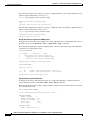
Step 2
When the following message appears, enter yes to begin the initial configuration dialog:
Would you like to enter the initial configuration dialog? [yes/no]:
Note
If you answer no to this message, you are prompted to terminate AutoInstall. AutoInstall is
a procedure that configures a new router based on the configuration of an existing router.
If you terminate AutoInstall, you enter the Cisco IOS software CLI.
Note
The interface numbering that appears in the next step is dependent on the type of
Cisco modular router platform. This example shows a Cisco 2600 series router.
Software Configuration Guide for Cisco 2600 Series, Cisco 3600 Series, and Cisco 3700 Series Routers
OL-1957-03
2-3
Chapter 2
Using the Setup Command Facility
Configuring Global Parameters
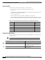
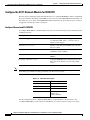
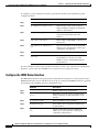
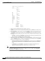
Step 3
When the following message appears, press Return to see the current interface summary:
First, would you like to see the current interface summary? [yes]:
Any interface listed with OK? value “NO” does not have a valid configuration
Interface
Ethernet0/0
Serial0/0
BRI0/0
Serial0/1
Serial0/2
Step 4
IP-Address
unassigned
unassigned
unassigned
unassigned
unassigned
OK?
NO
NO
NO
NO
NO
Method
unset
unset
unset
unset
unset
Status
up
up
up
up
up
Protocol
up
down
up
down
down
Enter a host name for the router (this example uses 2600):
Configuring global parameters:
Enter host name [Router]: 2600
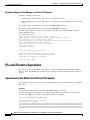
The enable secret is a password used to protect access to privileged EXEC and
configuration modes. This password, after entered, becomes encrypted in the configuration.
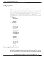
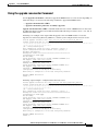
Step 5
Enter an enable secret password. This password is encrypted (more secure) and cannot be seen when
viewing the configuration:
Enter enable secret: xxxx
The enable password is used when you do not specify an enable secret password, with some
older software versions, and some boot images.
Step 6
Enter an enable password that is different from the enable secret password. This password is not
encrypted (less secure) and can be seen when viewing the configuration:
Enter enable password: guessme
The virtual terminal password is used to protect access to the router over a network
interface.
Step 7
Enter the virtual terminal password, which prevents unauthenticated access to the router through ports
other than the console port:
Enter virtual terminal password: guessagain
Step 8
Respond to the following prompts as appropriate for your network:
Configure SNMP Network Management? [yes]:
Community string [public]:
Configure LAT? [no]:
Configure AppleTalk? [no]:
Configure DECnet? [no]:
Configure IP? [yes]:
Configure IGRP routing? [yes]:
Your IGRP autonomous system number [1]: 15
Note
If you answer no to IGRP, you are prompted to configure RIP.
Configure
Configure
Configure
Configure
Configure
Configure
CLNS? [no]:
IPX? [no]:
Vines? [no]:
XNS? [no]:
Apollo? [no]:
bridging? [no]:
Software Configuration Guide for Cisco 2600 Series, Cisco 3600 Series, and Cisco 3700 Series Routers
2-4
OL-1957-03
Chapter 2
Using the Setup Command Facility
Configuring Global Parameters
Step 9
Configure the ISDN switch type used by the Basic Rate Interface (BRI) module:
BRI interface needs isdn switch-type to be configured
Valid switch types are :
[0] none..........Only if you don't want to configure BRI.
[1] basic-1tr6....1TR6 switch type for Germany
[2] basic-5ess....AT&T 5ESS switch type for the US/Canada
[3] basic-dms100..Northern DMS-100 switch type for US/Canada
[4] basic-net3....NET3 switch type for UK and Europe
[5] basic-ni......National ISDN switch type
[6] basic-ts013...TS013 switch type for Australia
[7] ntt...........NTT switch type for Japan
[8] vn3...........VN3 and VN4 switch types for France
Choose ISDN BRI Switch Type [2]:
Step 10
Configure the asynchronous serial lines for the integrated modems on the modules installed in the router.
(If you want to allow users to dial in through the integrated modems, you must configure the
asynchronous lines.)
Async lines accept incoming modems calls. If you will have
users dialing in via modems, configure these lines.
Configure Async lines? [yes]:
Async line speed [115200]:
Note
Cisco recommends that you do not change this speed.
Will you be using the modems for inbound dialing? [yes]:
Note
If your asynchronous interfaces will be using the same basic configuration parameters, Cisco
recommends answering yes to the next prompt. That way, you group the modems so that they
can be configured as a group. Otherwise, you will need to configure each interface separately.
Would you like to put all async interfaces in a group and configure them all at one time?
[yes]:
Allow dial-in users to choose a static IP addresses? [no]:
Configure for TCP header compression? [yes]:
Configure for routing updates on async links? [no]:
Enter the starting address of IP local pool? [X.X.X.X]:
172.20.30.40
Note
Make sure the starting and ending addresses of the IP pool are in the same subnet.
Enter the ending address of IP local pool? [X.X.X.X]: 172.20.30.88
You can configure a test user to verify that your
dial-up service is working properly
What is the username of the test user? [user]:
What is the password of the test user? [passwd]:
Will you be using the modems for outbound dialing? [no]:
Configuring interface parameters:
Software Configuration Guide for Cisco 2600 Series, Cisco 3600 Series, and Cisco 3700 Series Routers
OL-1957-03
2-5
Chapter 2
Using the Setup Command Facility
Configuring Interface Parameters
Configuring Interface Parameters
From this point on in the setup process, the prompts you see vary depending on the network modules
and WAN interface cards in place in your router. The following sections provide examples of the setup
steps for each interface module. Refer to the sections appropriate to your router.
Configuration for network modules includes:
•
Ethernet Interface Configuration, page 2-6
•
FastEthernet Interface Configuration, page 2-6
•
Token Ring Interface Configuration, page 2-7
•
Serial Interface Configuration, page 2-7
•
Asynchronous/Synchronous Serial Interface Configuration, page 2-10
•
ISDN BRI Interface Configuration, page 2-12
•
E1/T1 ISDN PRI Configuration, page 2-18
– E1/T1 PRI Mode, page 2-18
– E1 Channelized Mode, page 2-18
– T1 Channelized Mode, page 2-21
•
1-Port, 4-Wire 56-kbps DSU/CSU Configuration Setup, page 2-22
When you complete the setup steps for your interface modules, go to the “Completing the Configuration”
section on page 2-24 for directions on saving your configuration.
Ethernet Interface Configuration
This section contains a sample configuration for the Ethernet interface. Enter the values appropriate for
your router and network. The messages you see may vary.
Do you want to configure Ethernet0/0 interface [yes]:
Configure IP on this interface? [yes]:
IP address for this interface: 255.255.255.0
Subnet mask for this interface [255.0.0.0]:
Class A network is 1.0.0.0, 8 subnet bits, mask is /8
Configure IPX on this interface? [no]: y
IPX network number [1]:
Need to select encapsulation type
[0] sap (IEEE 802.2)
[1] snap (IEEE 802.2 SNAP)
[2] arpa (Ethernet_II)
[3] novell-ether (Novell Ethernet_802.3)
Enter the encapsulation type [2]:
FastEthernet Interface Configuration
This section contains a sample configuration for the FastEthernet interface. Enter the values appropriate
for your router and network. The messages you see may vary.
Do you want to configure FastEthernet0/0 interface [yes]:
Use the 100 Base-TX (RJ-45) connector? [yes]:
Operate in full-duplex mode? [no]:
Configure IP on this interface? [no]: yes
IP address for this interface: 6.0.0.1
Software Configuration Guide for Cisco 2600 Series, Cisco 3600 Series, and Cisco 3700 Series Routers
2-6
OL-1957-03
Chapter 2
Using the Setup Command Facility
Configuring Interface Parameters
Number of bits in subnet field [0]:
Class A network is 6.0.0.0, 0 subnet bits, mask is /8
Configure IPX on this interface? [yes]:
IPX network number [1]:
Need to select encapsulation type
[0] sap (IEEE 802.2)
[1] snap (IEEE 802.2 SNAP)
[2] arpa (Ethernet_II)
[3] novell-ether (Novell Ethernet_802.3)
Enter the encapsulation type [2]:
Token Ring Interface Configuration
This section contains a sample configuration for the Token Ring interface. Enter the values appropriate
for your router and network. The messages you see may vary.
Do you want to configure TokenRing0/0 interface? [yes]:
Tokenring ring speed (4 or 16)? [16]:
Configure IP on this interface? [yes]:
IP address for this interface: 1.0.0.1
Subnet mask for this interface [255.0.0.0]:
Class A network is 1.0.0.0, 8 subnet bits; mask is /8
Configure IPX on this interface? [no]: y
IPX network number [1]:
Need to select encapsulation type
[0] sap (IEEE 802.2)
[1] snap (IEEE 802.2 SNAP)
Enter the encapsulation type [0]:
Serial Interface Configuration
This section contains a sample configuration for the 1- or 2-port serial interface. Enter the values
appropriate for your router and network. The messages you see may vary.
Do you want to configure Serial0/0 interface? [yes]:
Some encapsulations supported are
ppp/hdlc/frame-relay/lapb/atm-dxi/smds/x25
Choose encapsulation type
[ppp]:
Note
The following sections describe the prompts for each encapsulation type. For PPP and HDLC
encapsulation, no further configuration is needed.
No serial cable seen.
Choose mode from (dce/dte) [dte]:
Note
If no cable is plugged in to your router, you need to indicate whether the interface is to be used as
DTE or DCE. If a cable is present, the setup command facility determines the DTE/DCE status. If
the serial cable is DCE, you see the following prompt:
Serial interface needs clock rate to be set in dce mode.
The following clock rates are supported on the serial interface.
0
1200, 2400, 4800, 9600, 19200, 38400
56000, 64000, 72000, 125000, 148000, 500000
Software Configuration Guide for Cisco 2600 Series, Cisco 3600 Series, and Cisco 3700 Series Routers
OL-1957-03
2-7
Chapter 2
Using the Setup Command Facility
Configuring Interface Parameters
800000, 1000000, 1300000, 2000000, 4000000, 8000000
Choose clock rate from above: [2000000]:
Configure IP on this interface? [yes]:
IP address for this interface: 2.0.0.1
Subnet mask for this interface [255.0.0.0]:
Class A network is 2.0.0.0, 8 subnet bits; mask is /8
Configure IPX on this interface? [no]: yes
IPX network number [8]:
Frame Relay Encapsulation
The following lmi-types are available to be set,
when connected to a frame relay switch
[0] none
[1] ansi
[2] cisco
[3] q933a
Enter lmi-type [2]:
Note
The setup command facility only prompts for the data-link connection identifier (DLCI) number if
you specify none for the Local Management Interface (LMI) type. If you accept the default or specify
another LMI type, the DLCI number is provided by the specified protocol.
Enter the DLCI number for this interface [16]:
Do you want to map a remote machine’s IP address to dlci? [yes]:
IP address for the remote interface: 2.0.0.2
Do you want to map a remote machine’s IPX address to dlci? [yes]:
IPX address for the remote interface: 40.1234.5678
Serial interface needs clock rate to be set in dce mode.
The following clock rates are supported on the serial interface.
0
1200, 2400, 4800, 9600, 19200, 38400
56000, 64000, 72000, 125000, 148000, 500000
800000, 1000000, 1300000, 2000000, 4000000, 8000000
choose speed from above: [2000000]: 1200
Configure IP on this interface? [yes]:
IP address for this interface: 2.0.0.1
Subnet mask for this interface [255.0.0.0]:
Class A network is 2.0.0.0, 8 subnet bits; mask is /8
If IPX is configured on the router, the setup command facility prompts for the IPX map:
Do you want to map a remote machine's IPX address to dlci? [yes]:
IPX address for the remote interface: 40.0060.34c6.90ed
LAPB Encapsulation
lapb circuit can be either in dce/dte mode.
Choose either from (dce/dte) [dte]:
Software Configuration Guide for Cisco 2600 Series, Cisco 3600 Series, and Cisco 3700 Series Routers
2-8
OL-1957-03
Chapter 2
Using the Setup Command Facility
Configuring Interface Parameters
X.25 Encapsulation
x25 circuit can be either in dce/dte mode.
Choose from either dce/dte [dte]:
Enter local x25 address: 1234
We will need to map the remote x.25 station’s x25 address
to the remote stations IP/IPX address
Enter remote x25 address: 4321
Do you want to map the remote machine’s x25 address to IP address? [yes]:
IP address for the remote interface: 2.0.0.2
Do you want to map the remote machine’s x25 address to IPX address? [yes]:
IPX address for the remote interface: 40.1234.5678
Enter
Enter
Enter
Enter
Enter
lowest 2-way channel [1]:
highest 2-way channel [64]:
frame window (K) [7]:
Packet window (W) [2]:
Packet size (must be powers of 2) [128]:
ATM-DXI Encapsulation
Enter VPI number [1]:
Enter VCI number [1]:
Do you want to map the remote machine’s IP address to vpi and vci’s? [yes]:
IP address for the remote interface: 2.0.0.2
Do you want to map the remote machine’s IPX address to vpi and vci’s? [yes]:
IPX address for the remote interface: 40.1234.5678
SMDS Encapsulation
Enter smds address for the local interface: c141.5556.1415
We will need to map the remote smds station’s address
to the remote stations IP/IPX address
Enter smds address for the remote interface: c141.5556.1414
Do you want to map the remote machine’s smds address to IP address? [yes]:
IP address for the remote interface: 2.0.0.2
Do you want to map the remote machine’s smds address to IPX address? [yes]:
IPX address for the remote interface: 40.1234.5678
Serial Cisco IOS Commands Generated
The following is an example of the Cisco IOS commands generated by a typical serial configuration:
interface Serial0/0
encapsulation ppp
clock rate 2000000
ip address 2.0.0.1 255.0.0.0
Software Configuration Guide for Cisco 2600 Series, Cisco 3600 Series, and Cisco 3700 Series Routers
OL-1957-03
2-9
Chapter 2
Using the Setup Command Facility
Configuring Interface Parameters
Asynchronous/Synchronous Serial Interface Configuration
This section contains sample configurations for an asynchronous/synchronous serial interface. Enter the
values appropriate for your router and network. The messages you see may vary.
Do you want to configure Serial1/0 interface? [yes]:
Enter mode (async/sync) [sync]:
Synchronous Configuration
If you select synchronous, you see screen displays similar to the following:
Do you want to configure Serial1/0 interface? [yes]:
Enter mode (async/sync) [sync]:
Some supported encapsulations are
ppp/hdlc/frame-relay/lapb/x25/atm-dxi/smds
Choose encapsulation type [hdlc]:
Note
The following sections describe the prompts for each encapsulation type. For PPP and HDLC
encapsulation, no further configuration is needed.
No serial cable seen.
Choose mode from (dce/dte) [dte]:
Note
If no cable is plugged in to your router, you need to indicate whether the interface is to be used as
DTE or DCE. If a cable is present, the setup command facility determines the DTE/DCE status. If
the serial cable is DCE, you see the following prompt:
Configure IP on this interface? [no]: yes
Configure IP unnumbered on this interface? [no]:
IP address for this interface: 2.0.0.0
Subnet mask for this interface [255.0.0.0]:
Class A network is 2.0.0.0, 0 subnet bits; mask is /8
Configure LAT on this interface? [no]:
Frame Relay Encapsulation
The following lmi-types are available to be set,
when connected to a frame relay switch
[0] none
[1] ansi
[2] cisco
[3] q933a
Enter lmi-type [2]:
Note
The setup command facility only prompts for the data-link connection identifier (DLCI) number if
you specify none for the Local Management Interface (LMI) type. If you accept the default or specify
another LMI type, the DLCI number is provided by the specified protocol.
Enter the DLCI number for this interface [16]:
Do you want to map a remote machine’s IP address to dlci? [yes]:
IP address for the remote interface: 2.0.0.2
Do you want to map a remote machine’s IPX address to dlci? [yes]:
IPX address for the remote interface: 40.1234.5678
Software Configuration Guide for Cisco 2600 Series, Cisco 3600 Series, and Cisco 3700 Series Routers
2-10
OL-1957-03
Chapter 2
Using the Setup Command Facility
Configuring Interface Parameters
Serial interface needs clock rate to be set in dce mode.
The following clock rates are supported on the serial interface.
0
1200, 2400, 4800, 9600, 19200, 38400
56000, 64000, 72000, 125000, 148000, 500000
800000, 1000000, 1300000, 2000000, 4000000, 8000000
choose speed from above: [2000000]: 1200
Configure IP on this interface? [yes]:
IP address for this interface: 2.0.0.1
Subnet mask for this interface [255.0.0.0]:
Class A network is 2.0.0.0, 8 subnet bits; mask is /8
Note
If IPX is configured on the router, the setup command facility prompts for the IPX map:
Do you want to map a remote machine's IPX address to dlci? [yes]:
IPX address for the remote interface: 40.0060.34c6.90ed
LAPB Encapsulation
lapb circuit can be either in dce/dte mode.
Choose either from (dce/dte) [dte]:
X.25 Encapsulation
x25 circuit can be either in dce/dte mode.
Choose from either dce/dte [dte]:
Enter local x25 address: 1234
We will need to map the remote x.25 station’s x25 address
to the remote stations IP/IPX address
Enter remote x25 address: 4321
Do you want to map the remote machine’s x25 address to IP address? [yes]:
IP address for the remote interface: 2.0.0.2
Do you want to map the remote machine’s x25 address to IPX address? [yes]:
IPX address for the remote interface: 40.1234.5678
Enter
Enter
Enter
Enter
Enter
lowest 2-way channel [1]:
highest 2-way channel [64]:
frame window (K) [7]:
Packet window (W) [2]:
Packet size (must be powers of 2) [128]:
ATM-DXI Encapsulation
Enter VPI number [1]:
Enter VCI number [1]:
Do you want to map the remote machine’s IP address to vpi and vci’s? [yes]:
IP address for the remote interface: 2.0.0.2
Do you want to map the remote machine’s IPX address to vpi and vci’s? [yes]:
IPX address for the remote interface: 40.1234.5678
Software Configuration Guide for Cisco 2600 Series, Cisco 3600 Series, and Cisco 3700 Series Routers
OL-1957-03
2-11
Chapter 2
Using the Setup Command Facility
Configuring Interface Parameters
SMDS Encapsulation
Enter smds address for the local interface: c141.5556.1415
We will need to map the remote smds station’s address
to the remote stations IP/IPX address
Enter smds address for the remote interface: c141.5556.1414
Do you want to map the remote machine’s smds address to IP address? [yes]:
IP address for the remote interface: 2.0.0.2
Do you want to map the remote machine’s smds address to IPX address? [yes]:
IPX address for the remote interface: 40.1234.5678
Asynchronous Configuration
If you select asynchronous, you see screen displays similar to the following:
Do you want to configure Serial1/1 interface? [yes]:
Enter mode (async/sync) [sync]: async
Configure IP on this interface? [yes]:
Configure IP unnumbered on this interface? [no]:
IP address for this interface: 2.0.0.0
Subnet mask for this interface [255.0.0.0]:
Class A network is 2.0.0.0, 0 subnet bits; mask is /8
Configure LAT on this interface? [no]:
Configure AppleTalk on this interface? [no]:
Configure DECnet on this interface? [no]:
Configure CLNS on this interface? [no]:
Configure IPX on this interface? [no]: yes
IPX network number [8]:
Configure Vines on this interface? [no]:
Configure XNS on this interface? [no]:
Configure Apollo on this interface? [no]:
ISDN BRI Interface Configuration
Use the System Configuration Dialog to configure an ISDN BRI interface. This configuration requires
you to enter the ISDN switch type. These switch types are shown in Table 2-1.
Table 2-1
ISDN Switch Types
Country
ISDN Switch Type
Description
Australia
basic-ts013
Australian TS013 switches
Europe
basic-1tr6
German 1TR6 ISDN switches
basic-nwnet3
Norwegian NET3 ISDN switches (phase 1)
basic-net3
NET3 ISDN switches (UK and others)
basic-net5
NET5 switches (UK and others)
vn2
French VN2 ISDN switches
vn3
French VN3 ISDN switches
Japan
ntt
Japanese NTT ISDN switches
New Zealand
basic-nznet3
New Zealand NET3 switches
Software Configuration Guide for Cisco 2600 Series, Cisco 3600 Series, and Cisco 3700 Series Routers
2-12
OL-1957-03
Chapter 2
Using the Setup Command Facility
Configuring Interface Parameters
Table 2-1
ISDN Switch Types (continued)
Country
ISDN Switch Type
Description
North America
basic-5ess
AT&T basic rate switches
basic-dms100
NT DMS-100 basic rate switches
basic-ni1
National ISDN-1 switches
When you reach the following prompt on the System Configuration Dialog, enter an ISDN switch type
from Table 2-1:
BRI interface needs isdn switch-type to be configured
Valid switch types are:
[0] none..........Only if you don't want to configure BRI.
[1] basic-1tr6....1TR6 switch type for Germany
[2] basic-5ess....AT&T 5ESS switch type for the US/Canada
[3] basic-dms100..Northern DMS-100 switch type for US/Canada
[4] basic-net3....NET3 switch type for UK and Europe
[5] basic-ni......National ISDN switch type
[6] basic-ts013...TS013 switch type for Australia
[7] ntt...........NTT switch type for Japan
[8] vn3...........VN3 and VN4 switch types for France
Choose ISDN BRI Switch Type [2]:
Do you want to configure BRI0/0 interface? [yes]:
Some encapsulations supported are
ppp/hdlc/frame-relay/lapb/x25
Choose encapsulation type
[ppp]:
Note
The following sections describe the prompts for each encapsulation type. No further configuration is
needed for HDLC encapsulation.
Do you have a service profile identifiers (SPIDs) assigned? [no]: y
Enter SPID1: 12345
Enter SPID2: 12345
Note
The setup command facility only prompts for the SPID number if you specify basic-5ess, basic-ni1,
or basic-dms100 for the switch type.
Do you want to map the remote machine's
IP address for the remote interface:
Do you want to map the remote machine's
IPX address of the remote interface:
IP address in dialer map? [yes]:
2.0.0.1
IP address in dialer map? [yes]:
40.0060.34c6.90ed
To get to 2.0.0.1 we will need to make a phone call.
Please enter the phone number to call: 1234567890
Configure IP on this interface? [yes]:
Note
If your router has at least one configured LAN interface, you can choose to use an unnumbered IP
address on the interface.
Configure IP unnumbered on this interface? [no]: y
Assign to which interface [Ethernet0/0]:
Software Configuration Guide for Cisco 2600 Series, Cisco 3600 Series, and Cisco 3700 Series Routers
OL-1957-03
2-13
Chapter 2
Using the Setup Command Facility
Configuring Interface Parameters
Note
If your router does not have a configured LAN interface, you must use a numbered IP address.
IP address for this interface: 2.0.0.0.1
Enter the subnet mask [255.0.0.0]:
PPP Encapsulation
Would you like to enable multilink PPP [yes]:
Enter a remote hostname for PPP authentication [Router]:
Enter a password for PPP authentication:
Note
The password, which is used by the Challenge Handshake Authentication Protocol (CHAP)
authentication process, is case sensitive and must match the remote router’s password exactly.
Frame Relay Encapsulation
The following lmi-types are available to be set,
when connected to a frame relay switch
[0] none
[1] ansi
[2] cisco
[3] q933a
Enter lmi-type [2]:
Note
The setup command facility only prompts for the data-link connection identifier (DLCI) number if
you specify none for the Local Management Interface (LMI) type. If you accept the default or specify
another LMI type, the DLCI number is provided by the specified protocol.
Enter the DLCI number for this interface [16]:
Do you want to map a remote machine’s IP address to dlci? [yes]:
IP address for the remote interface: 2.0.0.2
Do you want to map a remote machine’s IPX address to dlci? [yes]:
IPX address for the remote interface: 40.1234.5678
Serial interface needs clock rate to be set in dce mode.
The following clock rates are supported on the serial interface.
0
1200, 2400, 4800, 9600, 19200, 38400
56000, 64000, 72000, 125000, 148000, 500000
800000, 1000000, 1300000, 2000000, 4000000, 8000000
choose speed from above: [2000000]: 1200
Configure IP on this interface? [yes]:
IP address for this interface: 2.0.0.1
Subnet mask for this interface [255.0.0.0]:
Class A network is 2.0.0.0, 8 subnet bits; mask is /8
Note
If IPX is configured on the router, the setup command facility prompts for the IPX map:
Do you want to map a remote machine's IPX address to dlci? [yes]:
IPX address for the remote interface: 40.0060.34c6.90ed
Software Configuration Guide for Cisco 2600 Series, Cisco 3600 Series, and Cisco 3700 Series Routers
2-14
OL-1957-03
Chapter 2
Using the Setup Command Facility
Configuring Interface Parameters
LAPB Encapsulation
lapb circuit can be either in dce/dte mode
Choose either from (dce/dte) [dte]:
ATM-DXI Encapsulation
Enter VPI number [1]:
Enter VCI number [1]:
Do you want to map the remote machine's IP address to vpi and vci's? [yes]:
IP address for the remote interface: 6.0.0.1
Do you want to map the remote machine's IPX address to vpi and vci's? [yes]:
IPX address for the remote interface: 40.0060.34c6.90ed
SMDS Encapsulation
Enter smds address for the local interface: c141.5556.1415
We will need to map the remote smds station's address to the remote stations IP address
Enter smds address for the remote interface: c141.5556.1414
Do you want to map the remote machine's smds address to IP address? [yes]:
IP address for the remote interface: 2.0.0.1
Do you want to map the remote machine's smds address to IP address? [yes]:
IPX address for the remote interface: 40.0060.34c6.90ed
X.25 Encapsulation
x25 circuit can be either in dce/dte mode.
Choose from either dce/dte [dte]:
Enter local x25 address: 1234
We will need to map the remote x.25 station's x25 address
to the remote stations IP/IPX address
Do you want to map the remote machine's x25 address to IP address? [yes]:
IP address for the remote interface: 6.0.0.1
Do you want to map the remote machine's x25 address to IPX address? [yes]:
IPX address for the remote interface: 40.0060.34c6.90ed
Enter remote x25 address: 4321
Enter lowest 2-way channel [1]:
Enter highest 2-way channel [64]:
Enter frame window (K) [7]:
Enter Packet window (W) [2]:
Enter Packet size (must be powers of 2) [128]:
ISDN BRI Line Configuration
Before using a router with an ISDN BRI interface, you must order a correctly configured ISDN BRI line
from your local telecommunications service provider.
The ordering process varies from provider to provider and from country to country. However, here are
some general guidelines:
•
Ask for two channels to be called by one number.
•
Ask for delivery of calling line identification, also known as caller ID or Automatic Number
Identification (ANI).
•
If the router will be the only device attached to the ISDN BRI line, ask for point-to-point service
and a data-only line.
Software Configuration Guide for Cisco 2600 Series, Cisco 3600 Series, and Cisco 3700 Series Routers
OL-1957-03
2-15
Chapter 2
Using the Setup Command Facility
Configuring Interface Parameters
•
If you plan to connect another ISDN device (such as an ISDN telephone) to the ISDN BRI line
through the router, ask for point-to-multipoint service (subaddressing is required) and a
voice-and-data line.
ISDN BRI Provisioning by Switch Type
ISDN BRI provisioning refers to the types of services provided by the ISDN BRI line. Although
provisioning is performed by your ISDN BRI service provider, you must tell the provider what you want.
Table 2-2 lists the provisioning you should order for the router based on switch type.
Table 2-2
ISDN Provisioning by Switch Type
Switch Type
Provisioning
5ESS Custom BRI
For data only
2 B channels for data
Point to point
Terminal type = E
1 directory number (DN) assigned by service provider
MTERM = 1
Request delivery of calling line ID on Centrex lines
Set speed for ISDN calls to 56 kbps outside local exchange
5ESS Custom BRI
For voice and data
(Use these values only if you have an ISDN telephone connected.)
2 B channels for voice or data
MultiPoint
Terminal type = D
2 directory numbers assigned by service provider
2 service profile identifiers (SPIDs) required, assigned by service provider
MTERM = 2
Number of call appearances = 1
Display = No
Ringing/idle call appearances = idle
Autohold= no
Onetouch = no
Request delivery of calling line ID on Centrex lines
Set speed for ISDN calls to 56 kbps outside local exchange
Directory number 1 can hunt to directory number 2
Software Configuration Guide for Cisco 2600 Series, Cisco 3600 Series, and Cisco 3700 Series Routers
2-16
OL-1957-03
Chapter 2
Using the Setup Command Facility
Configuring Interface Parameters
Table 2-2
ISDN Provisioning by Switch Type (continued)
Switch Type
Provisioning
5ESS National ISDN
(NI-1) BRI
Terminal type = A
2 B channels for voice and data
2 directory numbers assigned by service provider
2 SPIDs required; assigned by service provider
Set speed for ISDN calls to 56 kbps outside local exchange
Directory number 1 can hunt to directory number 2
DMS-100 BRI
2 B channels for voice and data
2 directory numbers assigned by service provider
2 SPIDs required; assigned by service provider
Functional signaling
Dynamic terminal endpoint identifier (TEI) assignment
Maximum number of keys = 64
Release key = no, or key number = no
Ringing indicator = no
EKTS = no
PVC = 2
Request delivery of calling line ID on Centrex lines
Set speed for ISDN calls to 56 kbps outside local exchange
Directory number 1 can hunt to directory number 2
Defining ISDN Service Profile Identifiers
Some service providers assign service profile identifiers (SPIDs) to define the services subscribed to by
an ISDN device. If your service provider requires SPIDs, your ISDN device cannot place or receive calls
until it sends a valid SPID to the service provider when initializing the connection. A SPID is usually a
seven-digit telephone number plus some optional numbers, but service providers may use different
numbering schemes. SPIDs have significance at the local access ISDN interface only; remote routers are
never sent the SPID.
Currently, only DMS-100 and NI-1 switch types require SPIDs. Two SPIDs are assigned for the
DMS-100 switch type, one for each B channel. The AT&T 5ESS switch type may support SPIDs, but
Cisco recommends that you set up that ISDN service without SPIDs.
If your service provider assigns you SPIDs, you must define these SPIDs on the router. To define SPIDs
and the local directory number (LDN) on the router for both ISDN BRI B channels, use the following
isdn spid commands:
Router(config-if)# isdn spid1 spid-number [ldn]
Router(config-if)# isdn spid2 spid-number [ldn]
Note
Although the LDN is an optional parameter in the command, you may need to enter it so the router
can answer calls made to the second directory number.
Software Configuration Guide for Cisco 2600 Series, Cisco 3600 Series, and Cisco 3700 Series Routers
OL-1957-03
2-17
Chapter 2
Using the Setup Command Facility
Configuring Interface Parameters
E1/T1 ISDN PRI Configuration
This section contains a sample configuration for the channelized E1/T1 ISDN PRI interface. Enter the
values appropriate for your router and network. The messages you see may vary.
The following ISDN switch types are available:
[0] none............If you do not want to configure ISDN
[1] primary-4ess....AT&T 4ESS switch type for US and Canada
[2] primary-5ess....AT&T 5ESS switch type for US and Canada
[3] primary-dms100..Northern Telecom switch type for US and Canada
[4] primary-net5....European switch type for NET5
[5] primary-ni......National ISDN Switch type for the U.S
[6] primary-ntt.....Japan switch type
[7] primary-ts014...Australian switch type
Choose ISDN PRI Switch Type [2]:
Configuring controller T1 1/0 in pri or channelized mode
Do you want to configure this interface controller? [no]:
Will you be using PRI on this controller? [yes]:
E1/T1 PRI Mode
The following is an example of a E1/T1 PRI mode configuration using the setup command facility:
The following framing types are available:
esf | sf
Enter the framing type [esf]:
The following linecode types are available:
ami | b8zs
Enter the line code type [b8zs]:
Enter number of time slots [24]:
Do you want to configure Serial1/0:23 interface? [yes]:
Configuring the PRI D-channel
Would you like to enable multilink PPP? [yes]:
Configure IP on this interface? [no]: y
Configure IP unnumbered on this interface? [no]: y
Assign to which interface [Ethernet0/0]:
All users dialing in through the PRI will need to be
authenticated using CHAP. The username and password are
case sensitive.
Enter more username and passwords for PPP authentication? [no]: y
Enter the username used for dial-in CHAP authentication [Router]:
of the user dialling in on PRI:
Enter more username and passwords for PPP authentication? [no]:
Enter the PPP password
E1 Channelized Mode
The following is an example of an E1 channelized mode configuration using the setup command facility:
The following framing types are available:
no-crc4 | crc4
Enter the framing type [crc4]:
The following linecode types are available:
ami | hdb3
Enter the line code type [hdb3]:
Software Configuration Guide for Cisco 2600 Series, Cisco 3600 Series, and Cisco 3700 Series Routers
2-18
OL-1957-03
Chapter 2
Using the Setup Command Facility
Configuring Interface Parameters
Do you want to configure Serial1/1:0 interface?: [Yes]:
Configuring the Channelized E1/T1 serial channels
Some encapsulations supported are
ppp/hdlc/frame-relay/lapb/atm-dxi/smds/x25
Choose encapsulation type
[ppp]:
Configure IP on this interface? [no]: y
Configure IP unnumbered on this interface? [no]:
IP address for this interface: 3.0.0.1
Subnet mask for this interface [255.0.0.0]:
Class A network is 3.0.0.0, 8 subnet bits; mask is /8
Note
The following sections describe the prompts for each encapsulation type. No further configuration is
needed for HDLC encapsulation.
PPP Encapsulation
Would you like to enable multilink PPP [yes]:
Enter a remote hostname for PPP authentication [Router]:
Enter a password for PPP authentication:
Note
The password, which is used by the Challenge Handshake Authentication Protocol (CHAP)
authentication process, is case sensitive and must match the remote router’s password exactly.
Frame Relay Encapsulation
The following lmi-types are available to be set,
when connected to a frame relay switch
[0] none
[1] ansi
[2] cisco
[3] q933a
Enter lmi-type [2]:
Note
The setup command facility only prompts for the data-link connection identifier (DLCI) number if
you specify none for the Local Management Interface (LMI) type. If you accept the default or specify
another LMI type, the DLCI number is provided by the specified protocol.
Enter the DLCI number for this interface [16]:
Do you want to map a remote machine’s IP address to dlci? [yes]:
IP address for the remote interface: 2.0.0.2
Do you want to map a remote machine’s IPX address to dlci? [yes]:
IPX address for the remote interface: 40.1234.5678
Serial interface needs clock rate to be set in dce mode.
The following clock rates are supported on the serial interface.
0
1200, 2400, 4800, 9600, 19200, 38400
56000, 64000, 72000, 125000, 148000, 500000
800000, 1000000, 1300000, 2000000, 4000000, 8000000
Software Configuration Guide for Cisco 2600 Series, Cisco 3600 Series, and Cisco 3700 Series Routers
OL-1957-03
2-19
Chapter 2
Using the Setup Command Facility
Configuring Interface Parameters
choose speed from above: [2000000]: 1200
Configure IP on this interface? [yes]:
IP address for this interface: 2.0.0.1
Subnet mask for this interface [255.0.0.0]:
Class A network is 2.0.0.0, 8 subnet bits; mask is /8
Note
If IPX is configured on the router, the setup command facility prompts for the IPX map:
Do you want to map a remote machine's IPX address to dlci? [yes]:
IPX address for the remote interface: 40.0060.34c6.90ed
LAPB Encapsulation
lapb circuit can be either in dce/dte mode
Choose either from (dce/dte) [dte]:
ATM-DXI Encapsulation
Enter VPI number [1]:
Enter VCI number [1]:
Do you want to map the remote machine's IP address to vpi and vci's? [yes]:
IP address for the remote interface: 6.0.0.1
Do you want to map the remote machine's IPX address to vpi and vci's? [yes]:
IPX address for the remote interface: 40.0060.34c6.90ed
SMDS Encapsulation
Enter smds address for the local interface: c141.5556.1415
We will need to map the remote smds station's address to the remote stations IP address
Enter smds address for the remote interface: c141.5556.1414
Do you want to map the remote machine's smds address to IP address? [yes]:
IP address for the remote interface: 2.0.0.1
Do you want to map the remote machine's smds address to IP address? [yes]:
IPX address for the remote interface: 40.0060.34c6.90ed
X.25 Encapsulation
x25 circuit can be either in dce/dte mode.
Choose from either dce/dte [dte]:
Enter local x25 address: 1234
We will need to map the remote x.25 station's x25 address
to the remote stations IP/IPX address
Do you want to map the remote machine's x25 address to IP address? [yes]:
IP address for the remote interface: 6.0.0.1
Do you want to map the remote machine's x25 address to IPX address? [yes]:
IPX address for the remote interface: 40.0060.34c6.90ed
Enter remote x25 address: 4321
Enter lowest 2-way channel [1]:
Enter highest 2-way channel [64]:
Enter frame window (K) [7]:
Enter Packet window (W) [2]:
Enter Packet size (must be powers of 2) [128]:
Software Configuration Guide for Cisco 2600 Series, Cisco 3600 Series, and Cisco 3700 Series Routers
2-20
OL-1957-03
Chapter 2
Using the Setup Command Facility
Configuring Interface Parameters
T1 Channelized Mode
The following is an example of a T1 channelized mode configuration using the setup command facility:
The following framing types are available:
esf | sf
Enter the framing type [esf]:
The following linecode types are available:
ami | b8zs
Enter the line code type [b8zs]:
T1 is capable of being configured for channel 1-24
Enter number of time slots [24]: 3
Configure more channel groups? [no]: y
Enter number of time slots [21]: 3
Configure more channel groups? [no]: y
Enter number of time slots [18]: 3
Configure more channel groups? [no]: y
Enter number of time slots [15]:
Configure more channel groups? [no]:
Note
The following sections describe the prompts for each encapsulation type. No further configuration is
needed for HDLC encapsulation.
PPP Encapsulation
Would you like to enable multilink PPP [yes]:
Enter a remote hostname for PPP authentication [Router]:
Enter a password for PPP authentication:
Note
The password, which is used by the Challenge Handshake Authentication Protocol (CHAP)
authentication process, is case sensitive and must match the remote router’s password exactly.
Frame Relay Encapsulation
The following lmi-types are available to be set,
when connected to a frame relay switch
[0] none
[1] ansi
[2] cisco
[3] q933a
Enter lmi-type [2]:
Note
The setup command facility only prompts for the data-link connection identifier (DLCI) number if
you specify none for the Local Management Interface (LMI) type. If you accept the default or specify
another LMI type, the DLCI number is provided by the specified protocol.
Enter the DLCI number for this interface [16]:
Do you want to map a remote machine’s IP address to dlci? [yes]:
IP address for the remote interface: 2.0.0.2
Do you want to map a remote machine’s IPX address to dlci? [yes]:
IPX address for the remote interface: 40.1234.5678
Software Configuration Guide for Cisco 2600 Series, Cisco 3600 Series, and Cisco 3700 Series Routers
OL-1957-03
2-21
Chapter 2
Using the Setup Command Facility
Configuring Interface Parameters
Serial interface needs clock rate to be set in dce mode.
The following clock rates are supported on the serial interface.
0
1200, 2400, 4800, 9600, 19200, 38400
56000, 64000, 72000, 125000, 148000, 500000
800000, 1000000, 1300000, 2000000, 4000000, 8000000
choose speed from above: [2000000]: 1200
Configure IP on this interface? [yes]:
IP address for this interface: 2.0.0.1
Subnet mask for this interface [255.0.0.0]:
Class A network is 2.0.0.0, 8 subnet bits; mask is /8
If IPX is configured on the router, the setup command facility prompts for the IPX map:
Do you want to map a remote machine's IPX address to dlci? [yes]:
IPX address for the remote interface: 40.0060.34c6.90ed
LAPB Encapsulation
lapb circuit can be either in dce/dte mode
Choose either from (dce/dte) [dte]:
ATM-DXI Encapsulation
Enter VPI number [1]:
Enter VCI number [1]:
Do you want to map the remote machine's IP address to vpi and vci's? [yes]:
IP address for the remote interface: 6.0.0.1
Do you want to map the remote machine's IPX address to vpi and vci's? [yes]:
IPX address for the remote interface: 40.0060.34c6.90ed
SMDS Encapsulation
Enter smds address for the local interface: c141.5556.1415
We will need to map the remote smds station's address to the remote stations IP address
Enter smds address for the remote interface: c141.5556.1414
Do you want to map the remote machine's smds address to IP address? [yes]:
IP address for the remote interface: 2.0.0.1
Do you want to map the remote machine's smds address to IP address? [yes]:
IPX address for the remote interface: 40.0060.34c6.90ed
1-Port, 4-Wire 56-kbps DSU/CSU Configuration Setup
This section describes using setup command facility to configure a 1-port, 4-wire 56-kbps DSU/CSU
WAN interface card. It discusses the following:
•
Choosing Circuit-Switched or Dedicated-Line Service
•
Switched Mode
•
Dedicated Mode
Software Configuration Guide for Cisco 2600 Series, Cisco 3600 Series, and Cisco 3700 Series Routers
2-22
OL-1957-03
Chapter 2
Using the Setup Command Facility
Configuring Interface Parameters
Choosing Circuit-Switched or Dedicated-Line Service
The switched-56 WAN interface card is configured for dedicated or leased-line service by default, but it
can also be configured for circuit-switched service. Depending on the type of data transmissions you
typically use, you can configure the switched-56 WAN interface card for circuit-switched or
dedicated-line service.
Generally, circuit-switched service is ideal for short duration data transmissions or as an alternative route
if a dedicated line fails. For example, circuit-switched service is ideal for sending electronic mail
messages or doing such tasks as updating inventory and ordering records from one network database to
another at the end of each day.
Dedicated service is ideal for heavy network traffic. Dedicated service is ideal if you need a constant
network connection or you need connection for more than eight hours per day.
Switched Mode
The following is an example of a 1-port, 4-wire 56-kbps DSU/CSU switched-mode configuration using
the setup command facility:
Do you want to configure Serial0/0 interface? [yes]:
Some encapsulations supported are
ppp/hdlc/frame-relay/lapb/atm-dxi/smds/x25
Choose encapsulation type
[ppp]:
Switched 56k interface may either be in switched/Dedicated mode
Choose from either (switched/dedicated) [switched]:
The following switched carrier types are to be set when in switched mode
(at&t, sprint or other)
Choose carrier (at&t/sprint/other) [other]:
Do you want to map the remote machine's ip address in dialer map? [yes]:
IP address for the remote interface : 1.0.0.2
Do you want to map the remote machine's ipx address in dialer map? [yes]:
IPX address for the remote interface : 40.0060.34c6.90ed
Note
The setup command facility will ask for only one telephone number for both IP and IPX (if enabled).
Please enter the phone number to call : 1234567890
Configure IP on this interface? [yes]:
IP address for this interface: 1.0.0.1
Subnet mask for this interface [255.0.0.0] :
Class A network is 1.0.0.0, 8 subnet bits; mask is /8
Dedicated Mode
The following is an example of a 1-port, 4-wire 56-kbps DSU/CSU dedicated-mode configuration using
the setup command facility:
Do you want to configure Serial0/0 interface? [yes]:
Some encapsulations supported are
ppp/hdlc/frame-relay/lapb/atm-dxi/smds/x25
Choose encapsulation type
[ppp]:
Switched 56k interface may either be in switched/Dedicated mode
Choose from either (switched/dedicated) [switched]: dedi
Software Configuration Guide for Cisco 2600 Series, Cisco 3600 Series, and Cisco 3700 Series Routers
OL-1957-03
2-23
Chapter 2
Using the Setup Command Facility
Completing the Configuration
When in dds mode, the clock for sw56 module can either from line/internal.
Choose clock from (line/internal) [line]:
Note
If internal is selected, speed cannot be set to “auto.” Auto-sensing is only allowed when the clock
source is line.
When in dds mode, the clock for sw56 module can either from line/internal.
Choose clock from (line/internal) [line]: internal
Warning: internal can be choose only when connected back to back.
Serial interface needs clock rate to be set in dce mode.
The following clock rates are supported on the serial interface.
auto, 2.4, 4.8, 9.6, 19.2, 38.4
56, 64
choose clock rate from above [56]:
Configure IP on this interface? [yes]:
IP address for this interface: 1.0.0.1
Subnet mask for this interface [255.0.0.0] :
Class A network is 1.0.0.0, 8 subnet bits; mask is /8
Completing the Configuration
When you have provided all the information prompted for by the setup command facility, the
configuration appears. Some examples of the configurations of the Cisco 2600 Series, Cisco 3600 series,
and Cisco 3700 series routers are shown inAppendix A, “Configuration Examples.”
To complete your router configuration, do the following:
Step 1
A setup command facility prompt asks if you want to save this configuration.
If you answer no, the configuration information you entered is not saved, and you return to the router
enable prompt (2600#). Type setup to return to the System Configuration Dialog.
If you answer yes, the configuration is saved and your are returned to the EXEC prompt(2600>).
Use this configuration? {yes/no} : yes
Building configuration...
Use the enabled mode 'configure' command to modify this configuration.
Press RETURN to get started!
%LINK-3-UPDOWN:
%LINK-3-UPDOWN:
%LINK-3-UPDOWN:
%LINK-3-UPDOWN:
%LINK-3-UPDOWN:
%LINK-3-UPDOWN:
%LINK-3-UPDOWN:
%LINK-3-UPDOWN:
Interface
Interface
Interface
Interface
Interface
Interface
Interface
Interface
Ethernet0/0, changed state to up
Ethernet0/1, changed state to up
Serial0/0, changed state to up
Serial0/1, changed state to down
Serial0/2, changed state to down
Serial1/0, changed state to up
Serial1/1, changed state to down
Serial1/2, changed state to down
<Additional messages omitted.>
Software Configuration Guide for Cisco 2600 Series, Cisco 3600 Series, and Cisco 3700 Series Routers
2-24
OL-1957-03
Chapter 2
Using the Setup Command Facility
Where to Go Next
Step 2
When the messages stop displaying on your screen, press Return to get the 2600> prompt.
Note
If you see the next message, it means that no other AppleTalk routers were found on the
network attached to the port.
%AT-6-ONLYROUTER: Ethernet0/0: AppleTalk port enabled; no neighbors found
Step 3
The 2600> prompt indicates that you are now at the command-line interface (CLI) and you have just
completed a basic router configuration. However, this is not a complete configuration. At this point you
have two choices:
•
Run the setup command facility again and create another configuration. Enter the following:
2600> enable
Password: password
2600# setup
•
Modify the existing configuration or configure additional features with the CLI as described in
Chapter 3, “Configuring with the Command-Line Interface.”
Where to Go Next
At this point you can proceed to the following:
•
“Chapter 3, “Configuring with the Command-Line Interface,” to learn how to use the CLI to
configure additional features.
•
The Cisco IOS software configuration guide and command reference publications for more
advanced configuration topics. These publications are available on Cisco.com, the Documentation
CD-ROM that came with your router, or you can order printed copies. For more information, refer
to “Obtaining Documentation.”
Software Configuration Guide for Cisco 2600 Series, Cisco 3600 Series, and Cisco 3700 Series Routers
OL-1957-03
2-25
Chapter 2
Using the Setup Command Facility
Where to Go Next
Software Configuration Guide for Cisco 2600 Series, Cisco 3600 Series, and Cisco 3700 Series Routers
2-26
OL-1957-03
C H A P T E R
3
Configuring with the Command-Line Interface
This chapter describes how to use the Cisco IOS software command-line interface (CLI) to configure
basic router functionality, including:
•
Configuring the Host Name and Password, page 3-2
•
Configuring 1-Port and 2-Port Ethernet Interfaces, page 3-3
•
Configuring Fast Ethernet Interfaces, page 3-4
•
Configuring Asynchronous/Synchronous Serial Network Modules or WAN Interface Cards, page
3-5
•
Configuring 16-Port and 32-Port Asynchronous Network Modules, page 3-9
•
Configuring ISDN BRI WAN Interface Cards, page 3-10
•
Configuring T1 and E1 Interfaces, page 3-15
•
Configuring T1 (FT1) WAN Interface Cards, page 3-19
•
Configuring ATM Interfaces, page 3-20
•
Configuring Inverse Multiplexing for ATM Interfaces, page 3-23
•
Configuring Analog Modem Interfaces, page 3-26
•
Configuring Wireless Multipoint Interfaces, page 3-29
•
Configuring 1-Port ADSL WAN Interface Card, page 3-29
•
Configuring the NM-AIC-64, Contact Closure Network Module, page 3-34
•
Configuring the 1-Port HSSI Network Module, page 3-46
•
Configuring the Compression Network Module for the Cisco 3600 Series Routers, page 3-49
•
Configuring the Digital Modem Network Module for the Cisco 3640 Router, page 3-50
•
Configuring G.SHDSL on a Cisco Router, page 3-60
•
Saving Configuration Changes, page 3-65
•
Where to Go Next, page 3-65
Follow the procedures in this chapter to configure the router manually, or if you want to
change the configuration after you have run the setup command facility Using the Setup Command
Facility, page 2-1.
Software Configuration Guide for Cisco 2600 Series, Cisco 3600 Series, and Cisco 3700 Series Routers
OL-1957-03
3-1
Chapter 3
Configuring with the Command-Line Interface
Configuring the Host Name and Password
This chapter does not describe every configuration possible—only a small portion of the most commonly
used configuration procedures. For advanced configuration topics, refer to the Cisco IOS configuration
guide and command reference publications. These publications are available on the Documentation
CD-ROM that came with your router, on the World Wide Web from Cisco’s home page, or you can order
printed copies separately.
Note
If you skipped the previous chapter, Chapter 2, “Using the Setup Command Facility,” and you have
never configured a Cisco router, go back to that chapter and read it now. The chapter contains
important information you need to successfully configure your router.
Configuring the Host Name and Password
One of the first configuration tasks you might want to do is configure the host name and set an encrypted
password. Configuring a host name allows you to distinguish multiple Cisco routers from each other.
Setting an encrypted password allows you to prevent unauthorized configuration changes.
Command
Step 1 Router> enable
Password: password
Router#
Step 2 Router# configure terminal
Enter configuration commands, one per line.
End with CNTL/Z.
Purpose
Enter enable mode. Enter the password.
You have entered enable mode when the prompt
changes to Router#.
Enter global configuration mode. You have
entered global configuration mode when the
prompt changes to Router(config)#.
Router(config)#
Step 3 Router(config)# hostname Router
Router(config)#
Change the name of the router to a meaningful
name. Substitute your host name for Router.
Step 4 Router(config)# enable secret guessme
Enter an enable secret password. This password
provides access to privileged EXEC mode. When
a user types enable at the EXEC prompt
(Router> ), they must enter the enable secret
password to gain access to configuration mode.
Substitute your enable secret for guessme.
Step 5 Router(config)# line con 0
Enter line configuration mode to configure the
console port. When you enter line configuration
mode, the prompt changes to
Router(config-line)#.
Router(config-line)# exec-timeout 0 0
Prevent the router’s EXEC facility from timing out
if you do not type any information on the console
screen for an extended period.
Router(config-line)# exit
Exit back to global configuration mode.
Router(config)#
Software Configuration Guide for Cisco 2600 Series, Cisco 3600 Series, and Cisco 3700 Series Routers
3-2
OL-1957-03
Chapter 3
Configuring with the Command-Line Interface
Configuring 1-Port and 2-Port Ethernet Interfaces
Verifying the Host Name and Password
To verify that you configured the correct host name and password:
Step 1
Enter the show config command:
Router(config)# show config
Using 1888 out of 126968 bytes
!
version XX.X
.
.
.
!
hostname Router
!
enable secret 5 $1$60L4$X2JYOwoDc0.kqa1loO/w8/
.
.
.
Check the host name and encrypted password displayed near the top of the command output.
Step 2
Exit global configuration mode and attempt to re-enter it using the new enable password:
Router# exit
.
.
.
Router con0 is now available
Press RETURN to get started.
Router> enable
Password: guessme
Router#
Tip
If you are having trouble, check the following:
•
Caps Lock is off.
•
You entered the correct passwords. Passwords are case sensitive.
Configuring 1-Port and 2-Port Ethernet Interfaces
You can configure Ethernet interfaces manually by entering Cisco IOS commands on the command line.
This method, called configuration mode, provides the greatest power and flexibility.
Timesaver
Before you begin, disconnect all WAN cables from the router to keep it from trying to run the
AutoInstall process. The router tries to run AutoInstall whenever you power it on, if there is a WAN
connection on both ends and the router does not have a valid configuration file stored in nonvolatile
random-access memory (NVRAM) (for instance, when you add a new interface). It can take several
minutes for the router to determine that AutoInstall is not connected to a remote Transmission
Control Protocol/Internet Protocol (TCP/IP) host.
Software Configuration Guide for Cisco 2600 Series, Cisco 3600 Series, and Cisco 3700 Series Routers
OL-1957-03
3-3
Chapter 3
Configuring with the Command-Line Interface
Configuring Fast Ethernet Interfaces
Before you begin configuring the Ethernet interface, make sure you:
•
Connect a console to the router.
•
Power on the router.
Command
Step 1 Router> enable
Password: password
Router#
Step 2 Router# configure terminal
Enter configuration commands, one per line.
End with CNTL/Z.
Purpose
Enter enable mode. Enter the password.
You have entered enable mode when the prompt
changes to Router#.
Enter global configuration mode. You have
entered global configuration mode when the
prompt changes to Router(config)#.
Router(config)#
Step 3 Router# ip routing
Router# appletalk routing
Router# ipx routing
Step 4 Router(config)# interface ethernet 0/0
Router(config-if)#
Step 5 Router(config-if)# ip address 172.16.74.3
255.255.255.0
Step 6 Router(config-if)# appletalk static
cable-range 3-3
Router(config-if)# appletalk zone ZZEth
Router(config-if)# ipx network B005
Step 7 Router(config-if)# exit
Enable routing protocols as required for your
global configuration. This example uses IP
routing, AppleTalk routing, and Internetwork
Packet Exchange (IPX) routing.
Enter the interface configuration mode. You have
entered interface configuration mode when the
prompt changes to Router(config-if)#.
Assign the IP address and subnet mask to the
interface.
Configure routing protocols on the interface. You
must have previously enabled these protocols as
part of global configuration. In this example,
AppleTalk and IPX are being configured on the
interface.
Exit back to global configuration mode.
Repeat Step 4 through Step 6 if your router has
more that one LAN interface that you need to
configure.
Step 8 Router(config)# Ctrl-z
Router#
When you finish configuring interfaces, return to
enable mode.
Configuring Fast Ethernet Interfaces
To configure a Fast Ethernet interface, use the configuration software provided with your router or
network module, if any. Otherwise, for greatest power and flexibility use configuration mode (manual
configuration). In this mode, you enter Cisco IOS commands at the router prompt.
Note
Before you begin, disconnect all WAN cables from the router to keep it from trying to run the
AutoInstall process. The router tries to run AutoInstall whenever you power it on if there is a WAN
connection on both ends and the router does not have a valid configuration file stored in NVRAM
(for instance, when you add a new interface). It can take several minutes for the router to determine
that AutoInstall is not connected to a remote Transmission Control Protocol/Internet Protocol
(TCP/IP) host.
Software Configuration Guide for Cisco 2600 Series, Cisco 3600 Series, and Cisco 3700 Series Routers
3-4
OL-1957-03
Chapter 3
Configuring with the Command-Line Interface
Configuring Asynchronous/Synchronous Serial Network Modules or WAN Interface Cards
This section describes basic configuration, including enabling the interface and specifying IP routing.
Depending on your own requirements and the protocols you plan to route, you might also need to enter
other configuration commands.
Before you begin configuring the interfaces, make sure you:
•
Connect a console to the router.
•
Power on the router.
Command
Purpose
Step 1 Router> enable
Password: password
Router#
Step 2 Router# configure terminal
Enter configuration commands, one per line.
End with CNTL/Z.
Enter enable mode. Enter the password.
You have entered enable mode when the prompt
changes to Router#.
Enter global configuration mode. You have
entered global configuration mode when the
prompt changes to Router(config)#.
Router(config)#
Step 3 Router# ip routing
Router# appletalk routing
Router# ipx routing
Step 4 Router(config)# interface fastethernet 0/0
Router(config-if)#
Step 5 Router(config-if)# ip address 172.16.74.3
255.255.255.0
Step 6 Router(config-if)# appletalk static
cable-range 3-3
Router(config-if)# appletalk zone ZZEth
Router(config-if)# ipx network B005
Step 7 Router(config-if)# exit
Enable routing protocols as required for your
global configuration. This example uses IP
routing, AppleTalk routing, and Internetwork
Packet Exchange (IPX) routing.
Enter interface configuration mode. You have
entered interface configuration mode when the
prompt changes to Router(config-if)#.
Assign an IP address and subnet mask to the
interface.
Configure routing protocols on the interface. You
must have previously enabled these protocols as
part of global configuration. In this example,
AppleTalk and IPX are being configured on the
interface.
Exit back to global configuration mode.
Repeat Step 4 through Step 6 if your router has
more than one interface that you need to
configure.
Step 8 Router(config)# Ctrl-z
Router#
When you finish configuring interfaces, return to
enable mode.
Configuring Asynchronous/Synchronous Serial Network
Modules or WAN Interface Cards
You can configure the serial interfaces on your asynchronous/synchronous serial network module or
WAN interface card manually by entering Cisco IOS commands on the command line. This method,
called configuration mode, provides the greatest power and flexibility.
Software Configuration Guide for Cisco 2600 Series, Cisco 3600 Series, and Cisco 3700 Series Routers
OL-1957-03
3-5
Chapter 3
Configuring with the Command-Line Interface
Configuring Asynchronous/Synchronous Serial Network Modules or WAN Interface Cards
Timesaver
Before you begin, disconnect all WAN cables from the router to keep it from trying to run the
AutoInstall process. The router tries to run AutoInstall whenever you power it ON, if there is a WAN
connection on both ends and the router does not have a valid configuration file stored in nonvolatile
random-access memory (NVRAM) (for instance, when you add a new interface). It can take several
minutes for the router to determine that AutoInstall is not connected to a remote Transmission
Control Protocol/Internet Protocol (TCP/IP) host.
Before you begin configuring the asynchronous/synchronous serial interface, make sure you:
•
Connect a console to the router.
•
Power on the router.
Command
Step 1 Router> enable
Password: password
Router#
Step 2 Router# configure terminal
Enter configuration commands, one per line.
End with CNTL/Z.
Purpose
Enter enable mode. Enter the password.
You have entered enable mode when the prompt
changes to Router#.
Enter global configuration mode. You have
entered global configuration mode when the
prompt changes to Router(config)#.
Router(config)#
Step 3 Router# ip routing
Router# appletalk routing
Router# ipx routing
Step 4 Router(config)# interface serial 0/0
Router(config-if)#
Step 5 Router(config-if)# ip address 172.16.74.1
255.255.255.0
Step 6 Router(config-if)# appletalk static
cable-range 5-5
Router(config-if)# appletalk zone ZZSerial
Router(config-if)# ipx network B003
Enable routing protocols as required for your
global configuration. This example uses IP
routing, AppleTalk routing, and Internetwork
Packet Exchange (IPX) routing.
Enter the interface configuration mode. You have
entered interface configuration mode when the
prompt changes to Router(config-if)#.
Assign the IP address and subnet mask to the
interface.
Configure routing protocols on the interface. You
must have previously enabled these protocols as
part of global configuration. In this example,
AppleTalk and IPX are being configured on the
interface.
Step 7 Router(config-if)# physical-layer async
All serial ports are initially configured as
synchronous. Enter this command if you want to
configure the port as asynchronous.
Step 8 Router(config-if)# async mode dedicated
Configure asynchronous parameters according to
your needs.
Router(config-if)# async default routing
Step 9 Router(config-if)# line async <#>
Configure the asynchronous line setting.
Step 10 Router(config-if)# half-duplex timer
Specify the time that the interface waits in
controlled carrier mode. See Table 3-1 for a list of
half-duplex timer commands.
dcd-drop-delay 100
Software Configuration Guide for Cisco 2600 Series, Cisco 3600 Series, and Cisco 3700 Series Routers
3-6
OL-1957-03
Chapter 3
Configuring with the Command-Line Interface
Configuring Asynchronous/Synchronous Serial Network Modules or WAN Interface Cards
Command
Purpose
Step 11 Router(config-if)# clockrate 7200
To use a port in DCE mode, connect a DCE cable
and set the internal transmit clock signal (TXC)
speed in bits per second. See Table 3-2 through
Table 3-5 for a list of clock rate settings for your
specific interface. (For ports used in DTE mode,
the router automatically uses the external timing
signal.)
Step 12 Router(config-if)#
When a port is operating in DCE mode, the default
operation is for the DCE to send serial clock
transmit (SCT) and serial clock receive (SCR)
clock signals to the DTE, and for the DTE to
return a serial clock transmit external (SCTE)
signal to the DCE.
dce-terminal-timing-enable
If the DTE does not return SCTE, enter this
command to configure the DCE port to use its own
clock signal.
Step 13 Router(config-if)# invert-txc
Routers that use long cables might experience
high error rates when operating at higher
transmission speeds, because the clock and data
signals can shift out of phase.
If a DCE port is reporting a high number of error
packets, inverting the clock using this command
can often correct the shift.
Step 14 Router(config-if)# nrzi-encoding
All serial interfaces support both nonreturn to zero
(NRZ) and nonreturn to zero inverted (NRZI)
formats. NRZ is the default; NRZI is commonly
used with EIA/TIA-232 connections in IBM
environments. To enable NRZI encoding on an
interface, enter this command.
Step 15 Router(config-if)# exit
Exit back to global configuration mode.
Repeat Step 4 through Step 14 if your router has
more that one serial interface that you need to
configure.
Step 16 Router(config)# Ctrl-z
Router#
When you finish configuring interface, return to
enable mode.
Software Configuration Guide for Cisco 2600 Series, Cisco 3600 Series, and Cisco 3700 Series Routers
OL-1957-03
3-7
Chapter 3
Configuring with the Command-Line Interface
Configuring Asynchronous/Synchronous Serial Network Modules or WAN Interface Cards
Table 3-1
Half-Duplex Timer Commands
Timer
Syntax
Default Setting (Milliseconds)
half-duplex timer cts-delay
100
CTS drop timeout
half-duplex timer
cts-drop-timeout
5000
DCD drop delay
half-duplex timer
dcd-drop-delay
100
DCD transmission start delay
half-duplex timer
dcd-txstart-delay
100
RTS2 drop delay
half-duplex timer
rts-drop-delay
100
RTS timeout
half-duplex timer rts-timeout
2000
Transmit delay
half-duplex timer
transmit-delay
0
CTS delay
1
1. CTS = Clear To Send.
2. RTS = Request To Send.
Table 3-2
Clock Rate Settings for 1-Port/2-Port Serial WAN Interface Card in Synchronous Mode
Timer (bits per
second)
Syntax (bits per
second)
Default Setting (bits
per second)
1200
38400
148000
2400
56000
500000
4800
57600
800000
9600
64000
1000000
14400
72000
1300000
19200
115200
2000000
28800
125000
4000000
32000
128000
148000
Table 3-3
Clock Rate Settings for 1-Port/2-Port Serial WAN Interface Card in Asynchronous Mode
Timer (bits per
second)
Syntax (bits per
second)
Default Setting (bits
per second)
1200
28800
72000
2400
32000
115200
4800
38400
125000
9600
56000
128000
14400
57600
19200
64000
Software Configuration Guide for Cisco 2600 Series, Cisco 3600 Series, and Cisco 3700 Series Routers
3-8
OL-1957-03
Chapter 3
Configuring with the Command-Line Interface
Configuring 16-Port and 32-Port Asynchronous Network Modules
Table 3-4
Clock Rate Settings for 2-Port Asynchronous/Synchronous Serial WAN Interface Card
Timer (bits per
second)
Syntax (bits per
second)
Default Setting (bits
per second)
1200
28800
72000
2400
32000
115200
4800
38400
125000
9600
56000
128000
14400
57600
19200
64000
Table 3-5
Clock Rate Settings for 4-Port/8-Port Asynchronous/Synchronous Serial Network Module
Timer (bits per
second)
Syntax (bits per
second)
Default Setting (bits
per second)
300
19200
64000
1200
28800
72000
2400
32000
115200
4800
38400
128000
9600
56000
14400
57600
Configuring 16-Port and 32-Port Asynchronous Network
Modules
You can configure the asynchronous interface manually by entering Cisco IOS commands on the
command line. This method, called configuration mode, provides the greatest power and flexibility.
Timesaver
Before you begin, disconnect all WAN cables from the router to keep it from trying to run the
AutoInstall process. The router tries to run AutoInstall whenever you power it ON, if there is a WAN
connection on both ends and the router does not have a valid configuration file stored in nonvolatile
random-access memory (NVRAM) (for instance, when you add a new interface). It can take several
minutes for the router to determine that AutoInstall is not connected to a remote Transmission
Control Protocol/Internet Protocol (TCP/IP) host.
Before you begin configuring the asynchronous interface, make sure you:
•
Connect a console to the router.
•
Power on the router.
Software Configuration Guide for Cisco 2600 Series, Cisco 3600 Series, and Cisco 3700 Series Routers
OL-1957-03
3-9
Chapter 3
Configuring with the Command-Line Interface
Configuring ISDN BRI WAN Interface Cards
Command
Step 1 Router> enable
Password: password
Router#
Step 2 Router# configure terminal
Enter configuration commands, one per line.
End with CNTL/Z.
Purpose
Enter enable mode. Enter the password.
You have entered enable mode when the prompt
changes to Router#.
Enter global configuration mode. You have
entered global configuration mode when the
prompt changes to Router(config)#.
Router(config)#
Step 3 Router# ip routing
Router# appletalk routing
Router# ipx routing
Step 4 Router(config)# interface async 45
Router(config-if)#
Step 5 Router(config-if)# ip address 172.16.74.1
255.255.255.0
Step 6 Router(config-if)# appletalk static
cable-range 5-5
Router(config-if)# appletalk zone ZZAsync
Router(config-if)# ipx network B003
Step 7 Router(config-if)# async mode dedicated
Router(config-if)# async default routing
Enable routing protocols as required for your
global configuration. This example uses IP
routing, AppleTalk routing, and Internetwork
Packet Exchange (IPX) routing.
Enter the interface configuration mode and specify
the asynchronous interface to configure. You have
entered interface configuration mode when the
prompt changes to Router(config-if)#.
Assign the IP address and subnet mask to the
interface.
Configure routing protocols on the interface. You
must have previously enabled these protocols as
part of global configuration. In this example,
AppleTalk and IPX are being configured on the
interface.
Configure asynchronous parameters according to
your needs.
Router(config-if)# line async 45
Router(config-if)# speed 115200
Step 8 Router(config-if)# exit
Return to the global configuration mode and
repeat Step 4 through Step 7 if your router has
more than one interface that you need to
configure.
Step 9 Router(config)# Ctrl-z
Return to enable mode.
Router#
Configuring ISDN BRI WAN Interface Cards
You can configure the interfaces on your BRI WAN interface card manually by entering Cisco IOS
commands on the command line. This method, called configuration mode, provides the greatest power
and flexibility.
Software Configuration Guide for Cisco 2600 Series, Cisco 3600 Series, and Cisco 3700 Series Routers
3-10
OL-1957-03
Chapter 3
Configuring with the Command-Line Interface
Configuring ISDN BRI WAN Interface Cards
Timesaver
Before you begin, disconnect all WAN cables from the router to keep it from trying to run the
AutoInstall process. The router tries to run AutoInstall whenever you power it ON, if there is a WAN
connection on both ends and the router does not have a valid configuration file stored in nonvolatile
random-access memory (NVRAM) (for instance, when you add a new interface). It can take several
minutes for the router to determine that AutoInstall is not connected to a remote Transmission
Control Protocol/Internet Protocol (TCP/IP) host.
Before you begin configuring the BRI interface, make sure you:
•
Connect a console to the router.
•
Power on the router.
Command
Purpose
Step 1 Router> enable
Password: password
Router#
Step 2 Router# configure terminal
Enter configuration commands, one per line.
End with CNTL/Z.
Enter enable mode. Enter the password.
You have entered enable mode when the prompt
changes to Router#.
Enter global configuration mode. You have
entered global configuration mode when the
prompt changes to Router(config)#.
Router(config)#
Step 3 Router(config)# isdn switch-type basic-5ess
Enter an ISDN switch type. See Table 3-5 for a list
of ISDN switch types.
Note
Step 4 Router(config)# ip routing
Router(config)# appletalk routing
Router(config)# ipx routing
Step 5 Router(config)# interface bri 0/0
Router(config-if)#
Step 6 Router(config-if)# ip address 172.16.74.2
255.255.255.0
Router(config-if)# isdn switch-type
basic-5ess
Step 7 Router(config-if)# appletalk static
cable-range 5-5
Router(config-if)# appletalk zone ZZBRI
Router(config-if)# ipx network B004
Router(config-if)# isdn incoming-voice modem
Switch types configured in interface
configuration mode override this setting
for the configured interface.
Enable routing protocols as required for your
global configuration. This example uses IP
routing, AppleTalk routing, and Internetwork
Packet Exchange (IPX) routing.
Enter the interface configuration mode. You have
entered interface configuration mode when the
prompt changes to Router(config-if)#.
Assign the IP address and subnet mask to the
interface.
If you are configuring this interface for voice,
enter the switch type instead of an IP address.
Configure routing protocols on the interface. You
must have previously enabled these protocols as
part of global configuration. In this example,
AppleTalk and IPX are being configured on the
interface.
If you are configuring this router for voice, use the
isdn incoming-voice modem command.
Software Configuration Guide for Cisco 2600 Series, Cisco 3600 Series, and Cisco 3700 Series Routers
OL-1957-03
3-11
Chapter 3
Configuring with the Command-Line Interface
Configuring ISDN BRI WAN Interface Cards
Command
Purpose
Step 8 Router(config-if)# exit
Exit back to global configuration mode.
Repeat Step 5 through Step 7 if your router has
more than one BRI interface that you need to
configure.
Step 9 Router(config-if)# memory-size iomem 40
By default, the router allocates 25 percent of
DRAM to shared memory (used for data
transmitted or received by network modules and
WAN interface cards). If your router includes 16
or more ISDN BRI interfaces, you must increase
the amount of shared memory by entering the
memory-size iomem command. This example
increases shared memory from 25 percent to
40 percent.
Step 10 Router(config)# Ctrl-z
When you finish configuring interfaces, return to
enable mode.
Table 3-6
ISDN Switch Types
Country
ISDN Switch Type
Description
Australia
basic-ts013
Australian TS013 switches
Europe
basic-1tr6
German 1TR6 ISDN switches
basic-nwnet3
Norwegian NET3 ISDN switches (phase 1)
basic-net3
NET3 ISDN switches (UK and others)
vn2
French VN2 ISDN switches
vn3
French VN3 ISDN switches
Japan
ntt
Japanese NTT ISDN switches
New Zealand
basic-nznet3
New Zealand NET3 switches
North America
basic-5ess
AT&T basic rate switches
basic-dms100
NT DMS-100 basic rate switches
basic-nil1
National ISDN-1 switches
Configuring ISDN BRI Lines
Before using a router with an ISDN BRI interface, you must order a correctly configured ISDN BRI line
from your local telecommunications service provider.
Software Configuration Guide for Cisco 2600 Series, Cisco 3600 Series, and Cisco 3700 Series Routers
3-12
OL-1957-03
Chapter 3
Configuring with the Command-Line Interface
Configuring ISDN BRI WAN Interface Cards
The ordering process varies from provider to provider and from country to country; however, here are
some general guidelines:
•
Ask for two channels to be called by one number.
•
Ask for delivery of calling line identification, also known as caller ID or Automatic Number
Identification (ANI).
•
If the router will be the only device attached to the ISDN BRI line, ask for point-to-point service
and a data-only line.
•
If you plan to connect another ISDN device (such as an ISDN telephone) to the ISDN BRI line
through the router, ask for point-to-multipoint service (subaddressing is required) and a
voice-and-data line.
ISDN BRI Provisioning by Switch Type
ISDN BRI provisioning refers to the types of services provided by the ISDN BRI line. Although
provisioning is performed by your ISDN BRI service provider, you must tell the provider what you want.
Table 3-7 lists the provisioning you should order for your router.
Table 3-7
ISDN Provisioning by Switch Type
Switch Type
Provisioning
5ESS Custom BRI
For data only:
2 B channels for data
Point to point
Terminal type = E
1 directory number (DN) assigned by service provider
MTERM = 1
Request delivery of calling line ID on Centrex lines
Set speed for ISDN calls to 56 kbps outside local exchange
5ESS Custom BRI
For voice and data:
(Use these values only if you have an ISDN telephone connected.)|
2 B channels for voice or data
Multipoint
Terminal type = D
2 directory numbers assigned by service provider
2 service profile (SPIDs) required, assigned by service provider
MTERM = 2
Number of cal appearances = 1
Display = No
Ringing/idle call appearances = 1
Autohold = no
Onetouch = no
Request delivery of calling line ID on Centrex lines
Set speed for ISDN calls to 56 kbps outside local exchange
Directory number 1 can hunt to directory number 2
Software Configuration Guide for Cisco 2600 Series, Cisco 3600 Series, and Cisco 3700 Series Routers
OL-1957-03
3-13
Chapter 3
Configuring with the Command-Line Interface
Configuring ISDN BRI WAN Interface Cards
Table 3-7
ISDN Provisioning by Switch Type (continued)
Switch Type
Provisioning
5ESS National ISDN (NI-1) BRI Terminal type = A
2 B channels for voice or data
2 directory numbers assigned by service provider
2 SPIDs required, assigned by service provider
Set speed for ISDN calls to 56 kbps outside local exchange
Directory number 1 can hunt to directory number 2
DMS-100 BRI
2 B channels for voice or data
2 directory numbers assigned by service provider
2 SPIDs required, assigned by service provider
Functional signaling
Dynamic terminal endpoint identifier (TEI) assignment
Maximum number of keys = 64
Release key = no, or key number = no
Ringing indicator = no
EKTS = no
PVC = 2
Request delivery of calling line ID on Centrex lines
Set speed for ISDN calls to 56 kbps outside local exchange
Directory number 1 can hunt to directory number 2
Defining ISDN Service Profile Identifiers
Some service providers assign service profile identifiers (SPIDs) to define the services to which an ISDN
device subscribes. If your service provider requires SPIDs, your ISDN device cannot place or receive
calls until it sends a valid SPID to the service provider when initializing the connection. A SPID is
usually a seven-digit telephone number plus some optional numbers, but service providers might use
different numbering schemes. SPIDs have significance at the local access ISDN interface only; remote
routers are never sent the SPID.
Currently, only DMS-100 and NI-1 switch types require SPIDs. Two SPIDs are assigned for the
DMS-100 switch type, one for each B channel. The AT&T 5ESS switch type might support SPIDs, but
Cisco recommends that you set up that ISDN service without SPIDs.
If your service provider assigns you SPIDs, you must define these SPIDs on the router. To define SPIDs
and the local directory number (LDN) on the router for both ISDN BRI B channels, use the following
isdn spid commands:
Router (config-if)# isdn spid1
Router (config-if)# isdn spid2
Note
spid-number [ldn]
spid-number [ldn ]
Although the LDN is an optional parameter in the command, you might need to enter it so the router
can answer calls made to the second directory number.
For further information on configuring ISDN, see the chapters “Configuring ISDN” and “Configuring
DDR” in the Wide-Area Networking Configuration Guide publication, for your Cisco IOS software
release.
Software Configuration Guide for Cisco 2600 Series, Cisco 3600 Series, and Cisco 3700 Series Routers
3-14
OL-1957-03
Chapter 3
Configuring with the Command-Line Interface
Configuring T1 and E1 Interfaces
Configuring T1 and E1 Interfaces
To configure an ISDN PRI interface or T1/E1 multiflex trunk interface, use the configuration software
provided with your router or network module, if any. Otherwise, for greatest power and flexibility use
configuration mode (manual configuration). In this mode, you enter Cisco IOS commands at the router
prompt.
Note
Before you begin, disconnect all WAN cables from the router to keep it from trying to run the
AutoInstall process. The router tries to run AutoInstall whenever you power it on if there is a WAN
connection on both ends and the router does not have a valid configuration file stored in NVRAM
(for instance, when you add a new interface). It can take several minutes for the router to determine
that AutoInstall is not connected to a remote Transmission Control Protocol/Internet Protocol
(TCP/IP) host.
This section describes basic configuration, including enabling the interface and specifying IP routing.
Depending on your own requirements and the protocols you plan to route, you might also need to enter
other configuration commands.
Before you begin configuring the interfaces, make sure you:
•
Connect a console to the router.
•
Power on the router.
Configuring T1 Interfaces
Use the following procedure to configure a new T1, CT1/PRI or CT1/PRI-CSU interface or to change
the configuration of an existing interface.
Command
Purpose
Step 1 Router> enable
Password: password
Router#
Step 2 Router# configure terminal
Enter configuration commands, one per line.
End with CNTL/Z.
Router(config)#
Step 3 Router# ip routing
Router# appletalk routing
Router# ipx routing
Enter enable mode. Enter the password.
You have entered enable mode when the prompt
changes to Router#.
Enter global configuration mode. You have
entered global configuration mode when the
prompt changes to Router(config)#.
Enable routing protocols as required for your
global configuration. This example uses IP
routing, AppleTalk routing, and Internetwork
Packet Exchange (IPX) routing.
Step 4 Router(config)# controller t1 1/0
Select the CT1/PRI interface to configure. This
example configures a T1 interface in slot 1 and
unit 0.
Step 5 Router(config-controller)# clock source
Specify which end of the circuit provides
clocking. The clock source should be set to use
internal clocking only for testing the network or if
the full T1 line is used as the channel group. Only
one end of the T1 line should be set to internal.
line
Software Configuration Guide for Cisco 2600 Series, Cisco 3600 Series, and Cisco 3700 Series Routers
OL-1957-03
3-15
Chapter 3
Configuring with the Command-Line Interface
Configuring T1 and E1 Interfaces
Command
Purpose
Step 6 Router(config-controller)# framing esf
Specify the framing type.
Step 7 Router(config-controller)# linecode b8zs
Specify the line code format.
Step 8 Router(config-controller)# channel-group 0
timeslots 1,3-5,7
Specify the channel group and time slots to be
mapped. For multiflex trunk interfaces, only
channel 0 can be configured.
Step 9 Router(config-controller)# interface serial
Configure each channel group as a virtual serial
interface. Specify the T1 interface, unit number,
and channel group to modify.
1/0:0
Step 10 Router(config-if)# ip address 10.1.15.1
255.255.255.0
Step 11 Router(config-if)# appletalk static
cable-range 3-3
Router(config-if)# appletalk zone ZZEth
Router(config-if)# ipx network B005
Step 12 Router(config-if)# exit
Assign an IP address and subnet mask to the
interface.
Configure routing protocols on the interface. You
must have previously enabled these protocols as
part of global configuration. In this example,
AppleTalk and IPX are being configured on the
interface.
Exit back to global configuration mode.
Return to Step 4 if your router has more than one
CT1/PRI interface that you need to configure.
Step 13 Router(config)# Ctrl-z
Router#
When you finish configuring interfaces, return to
enable mode.
Configuring E1 Interfaces
Use the following procedure to configure a new E1 or CE1/PRI interface (balanced or unbalanced) or to
change the configuration of an existing interface.
Command
Step 1 Router> enable
Password: password
Router#
Step 2 Router# configure terminal
Enter configuration commands, one per line.
End with CNTL/Z.
Purpose
Enter enable mode. Enter the password.
You have entered enable mode when the prompt
changes to Router#.
Enter global configuration mode. You have
entered global configuration mode when the
prompt changes to Router(config)#.
Router(config)#
Step 3 Router# ip routing
Router# appletalk routing
Router# ipx routing
Enable routing protocols as required for your
global configuration. This example uses IP
routing, AppleTalk routing, and Internetwork
Packet Exchange (IPX) routing.
Step 4 Router(config)# controller e1 1/0
Select the CE1/PRI interface to configure. This
example configures an E1 interface in slot 1 and
unit 0.
Step 5 Router(config-controller)# framing crc4
Specify the framing type.
Step 6 Router(config-controller)# linecode hdb3
Specify the line code format.
Software Configuration Guide for Cisco 2600 Series, Cisco 3600 Series, and Cisco 3700 Series Routers
3-16
OL-1957-03
Chapter 3
Configuring with the Command-Line Interface
Configuring T1 and E1 Interfaces
Command
Purpose
Step 7 Router(config-controller)# channel-group 0
timeslots 1,3-5,7
Step 8 Router(config-controller)# interface serial
1/0:0
Step 9 Router(config-if)# ip address 10.1.15.1
255.255.255.0
Step 10 Router(config-if)# appletalk static
cable-range 3-3
Router(config-if)# appletalk zone ZZEth
Router(config-if)# ipx network B005
Step 11 Router(config-if)# exit
Specify the channel group and time slots to be
mapped. For multiflex trunk interfaces, only
channel 0 can be configured.
Configure each channel group as a virtual serial
interface. Specify the E1 interface, unit number,
and channel group to modify.
Assign an IP address and subnet mask to the
interface.
Configure routing protocols on the interface. You
must have previously enabled these protocols as
part of global configuration. In this example,
AppleTalk and IPX are being configured on the
interface.
Exit back to global configuration mode.
Return to Step 4 if your router has more than one
CE1/PRI interface that you need to configure.
Step 12 Router(config)# Ctrl-z
When you finish configuring interfaces, return to
enable mode.
Configuring TDM Connect (Data Pass-Through)
For multiflex trunk interfaces using the time-division multiplexing (TDM) connect function, you can use
the connect command to connect two groups of DS0 timeslots from two controllers.
To configure TDM connect, complete the following steps in controller configuration mode:
Command
Purpose
Step 1 To configure a TDM channel group for T1:
a Router(config-controller)# tdm-group
tdm-group-no timeslot timeslot-list [type
{e&m | fxs [loop-start | ground-start] |
fxo [loop-start | ground-start]}]
Configure a TDM channel group for T1. If
configuring cross-connect for data traffic only, do
not specify the type option. The type option only
applies if the mode cas command is enabled.
To configure a TDM channel gorup for E1:
b Router(config-controller)# tdm-group
tdm-group-no timeslot timeslot-list [type
{e&m | fxs [loop-start | ground-start] |
fxo [loop-start | ground-start] |
fxs-melcas | fxo-melcas | e&m-melcas}]
Configure a TDM channel group for E1. The
“melcas” options are supported only on E1 and
apply to the Mercury Exchange Limited (MEL)
Channel Associated Signaling (CAS) standard,
used primarily in the United Kingdom. The MEL
options help preserve CAS integrity on the line. If
configuring cross-connect for data traffic only, do
not specify the type option. The type option only
applies if the mode cas command is enabled.
Software Configuration Guide for Cisco 2600 Series, Cisco 3600 Series, and Cisco 3700 Series Routers
OL-1957-03
3-17
Chapter 3
Configuring with the Command-Line Interface
Configuring T1 and E1 Interfaces
Command
Purpose
Step 2 Router(config-controller)# exit
Exit controller configuration mode.
Step 3 Router(config)# connect id controller-1
Configure cross-connect pass-through between
two controllers.
tdm-group-no-1 controller-2 tdm-group-no-2
Configuring Codec Complexity
The number of channels that an HDV network module can support depends on the number of PVDMs
that are installed and the complexity level of the codecs (vocoders) needed to support the required
compression method. The HDV network module supports the following number of channels:
•
Up to 6 channels per PVDM (up to 30 channels for cards with 5 PVDMs installed) for high
complexity codecs (vocoders) that support the following services: G.711, G.726, G.729, G.723.1,
G.728, and fax relay
•
Up to 12 channels per PVDM (up to 60 channels for cards with 5 PVDMs installed) for medium
complexity codecs (vocoders) that support the following services: G.711, G.726, G.729a, and fax
relay
Each HDV network module can support only one type of compression complexity (either high or
medium), although HDV network modules with different compression complexity types can be installed
in the same router.
Use the following procedure to configure the codec (vocoder) complexity on your HDV network module.
Command
Step 1 Router> enable
Password: password
Router#
Step 2 Router# configure terminal
Enter configuration commands, one per line.
End with CNTL/Z.
Purpose
Enter enable mode. Enter the password.
You have entered enable mode when the prompt
changes to Router#.
Enter global configuration mode. You have
entered global configuration mode when the
prompt changes to Router(config)#.
Router(config)#
Step 3 Router(config)# voice-card {0-4}
Select the voice card to configure.
Step 4 Router(config-voicecard)# codec complexity
Specify the compression complexity for the voice
card.One complexity type is allowed per router.
{high |medium}
Step 5 Router(config-voicecard)# exit
Exit back to global configuration mode.
Return to Step 3 if your router has more than one
voice card that you need to configure.
Step 6 Router(config)# Ctrl-z
When you finish configuring interfaces, return to
enable mode.
Software Configuration Guide for Cisco 2600 Series, Cisco 3600 Series, and Cisco 3700 Series Routers
3-18
OL-1957-03
Chapter 3
Configuring with the Command-Line Interface
Configuring T1 (FT1) WAN Interface Cards
Configuring T1 (FT1) WAN Interface Cards
The 1-port T1 and fractional (FT1) WAN interface card includes an integrated data service unit/channel
service unit (DSU/CSU) and can be configured either for full T1 service at 1.544 Mbps or for
fractionalized T1 service. You can configure the interfaces on your T1 WAN interface card manually by
entering Cisco IOS commands on the command line. This method, called configuration mode, provides
the greatest power and flexibility.
Timesaver
Before you begin, disconnect all WAN cables from the router to keep it from trying to run the
AutoInstall process. The router tries to run AutoInstall whenever you power it ON, if there is a WAN
connection on both ends and the router does not have a valid configuration file stored in nonvolatile
random-access memory (NVRAM) (for instance, when you add a new interface). It can take several
minutes for the router to determine that AutoInstall is not connected to a remote Transmission
Control Protocol/Internet Protocol (TCP/IP) host.
Before you begin configuring the BRI interface, make sure you:
•
Connect a console to the router.
•
Power on the router.
Default Configuration
The Cisco IOS software provides the following default configuration for CSU/DSU- and T1-specific
parameters:
service-module t1
service-module t1
service-module t1
service-module t1
service-module t1
service-module t1
no service-module
service-module t1
no service-module
clock source line
data-coding normal
timeslots all speed 64
framing esf
lbo none
linecode b8zs
t1 remote-alarm-enable
remote-loopback
t1 fdl
To change this configuration, enter commands in configuration mode, as described in the next section.
To view the current configuration, enter the show service-module serial slot/port command. For further
information about these commands, refer to the Cisco IOS configuration guides and command
references.
Command
Purpose
Step 1 Router> enable
Password: password
Router#
Step 2 Router# configure terminal
Enter configuration commands, one per line.
End with CNTL/Z.
Enter enable mode. Enter the password.
You have entered enable mode when the prompt
changes to Router#.
Enter global configuration mode. You have
entered global configuration mode when the
prompt changes to Router(config)#.
Router(config)#
Software Configuration Guide for Cisco 2600 Series, Cisco 3600 Series, and Cisco 3700 Series Routers
OL-1957-03
3-19
Chapter 3
Configuring with the Command-Line Interface
Configuring ATM Interfaces
Command
Step 3 Router# ip routing
Router# appletalk routing
Router# ipx routing
Step 4 Router(config)# interface serial 0/0
Router(config-if)#
Step 5 Router(config-if)# ip address 172.16.74.2
255.255.255.0
Step 6 Router(config-if)# no keepalive
Router(config-if)# appletalk static
cable-range 5-5
Router(config-if)# appletalk zone ZZ
Router(config-if)# ipx network B004
Purpose
Enable routing protocols as required for your
global configuration. This example uses IP
routing, AppleTalk routing, and Internetwork
Packet Exchange (IPX) routing.
Enter the interface configuration mode. You have
entered interface configuration mode when the
prompt changes to Router(config-if)#.
Assign the IP address and subnet mask to the
interface
Configure routing protocols on the interface. You
must have previously enabled these protocols as
part of global configuration. In this example,
AppleTalk and IPX are being configured on the
interface.
Step 7 Router(config-if)# service-module t1 framing Enter the framing type and linecode type. In this
sf
Router(config-if)# service-module t1
linecode ami
Step 8 Router(config-if)# service-module t1
timeslots 1-20 speed 64
Step 9 Router(config-if)# exit
example, the framing type specified is sf
(Superframe) and the linecode specified is ami.
If you are using fractional T1 service, enter the
time slot range and speed. In this example, the
time slot range specified is from 1 to 20, and the
speed specified is 64 kbps.
Exit back to global configuration mode.
Repeat Step 4 through Step 8 if your router has
more than one interface that you need to
configure.
Step 10 Router(config)# Ctrl-z
Router#
When you finish configuring interfaces, return to
enable mode.
Configuring ATM Interfaces
To configure an ATM interface, you must use configuration mode (manual configuration). In this mode,
you enter Cisco IOS commands at the router prompt.
Note
Before you begin, disconnect all WAN cables from the router to keep it from trying to run the
AutoInstall process. The router tries to run AutoInstall whenever you power it on if there is a WAN
connection on both ends and the router does not have a valid configuration file stored in nonvolatile
random-access memory (NVRAM) (for instance, when you add a new interface). It can take several
minutes for the router to determine that AutoInstall is not connected to a remote Transmission
Control Protocol/Internet Protocol (TCP/IP) host.
This section describes basic configuration, including enabling the interface and specifying IP routing.
Depending on your own requirements and the protocols you plan to route, you might also need to enter
other configuration commands.
Software Configuration Guide for Cisco 2600 Series, Cisco 3600 Series, and Cisco 3700 Series Routers
3-20
OL-1957-03
Chapter 3
Configuring with the Command-Line Interface
Configuring ATM Interfaces
Configuring PVCs
To configure the ATM interface with PVCs, follow this procedure:
Command
Purpose
Step 1 Router> enable
Password: password
Router#
Step 2 Router# configure terminal
Enter configuration commands, one per line.
End with CNTL/Z.
Enter enable mode. Enter the password.
You have entered enable mode when the prompt
changes to Router#.
Enter global configuration mode. You have
entered global configuration mode when the
prompt changes to Router(config)#.
Router(config)#
Step 3 Router# ip routing
Router# appletalk routing
Router# ipx routing
Step 4 Router(config)# interface atm 1/0
Router(config-if)#
Step 5 Router(config-if)# ip address 192.168.74.3
255.255.255.0
Step 6 Router(config-if)# appletalk static
cable-range 3-3
Router(config-if)# appletalk zone ZZEth
Router(config-if)# ipx network B005
Step 7 Router(config-if)# pvc 0/100
Enable routing protocols as required for your
global configuration. This example uses IP
routing, AppleTalk routing, and Internetwork
Packet Exchange (IPX) routing.
Enter interface configuration mode. You have
entered interface configuration mode when the
prompt changes to Router(config-if)#.
Assign an IP address and subnet mask to the
interface.
Configure routing protocols on the interface. You
must have previously enabled these protocols as
part of global configuration. In this example,
AppleTalk and IPX are being configured on the
interface.
Configure a new ATM PVC. Enter
interface-ATM-VC configuration mode. The PVC
command has the format pvc [name] vpi/vci
[ilmi|qsaal] You have entered interface-ATM-VC
configuration mode when the prompt changes to
Router(config-if-atm-vc).
Step 8 Router(config-if-atm-vc)# protocol ip
Map the PVC to an address.
200.200.200.2 broadcast
Step 9 Router(config-if-atm-vc)# exit
Exit back to global configuration mode.
Repeat Step 4 through Step 8 if your router has
more than one interface that you need to
configure.
Step 10 Router(config)# Ctrl-z
When you finish configuring interfaces, return to
enable mode.
Software Configuration Guide for Cisco 2600 Series, Cisco 3600 Series, and Cisco 3700 Series Routers
OL-1957-03
3-21
Chapter 3
Configuring with the Command-Line Interface
Configuring ATM Interfaces
Configuring SVCs
To configure the ATM interface with switched virtual circuits (SVCs), follow this procedure:
Command
Step 1 Router> enable
Password: password
Router#
Step 2 Router# configure terminal
Enter configuration commands, one per line.
End with CNTL/Z.
Purpose
Enter enable mode. Enter the password.
You have entered enable mode when the prompt
changes to Router#.
Enter global configuration mode. You have
entered global configuration mode when the
prompt changes to Router(config)#.
Router(config)#
Step 3 Router# ip routing
Router# appletalk routing
Router# ipx routing
Step 4 Router(config)# interface atm 1/0
Router(config-if)#
Enable routing protocols as required for your
global configuration. This example uses IP
routing, AppleTalk routing, and Internetwork
Packet Exchange (IPX) routing.
Enter interface configuration mode. You have
entered interface configuration mode when the
prompt changes to Router(config-if)#.
Step 5 Router(config-if)# pvc 0/5 qsaal
Configure a signaling channel for the SVC.
Step 6 Router(config-if-atm-vc)# exit
Exit back to interface configuration mode.
Step 7 Router(config-if)# pvc 0/6 ilmi
Configure additional signaling channels for the
SVC.
Step 8 Router(config-if-atm-vc)# exit
Exit back to interface configuration mode.
Step 9 Router(config-if)# ip address 192.168.74.3
Assign an IP address and subnet mask to the
interface.
255.255.255.0
Step 10 Router(config-if)# appletalk static
cable-range 3-3
Router(config-if)# appletalk zone ZZEth
Router(config-if)# ipx network B005
Step 11 Router(config-if)# svc nsap
BC.CDEF.01.234567.890A.BCDE.F012.3456.7890.
1234.12
Configure routing protocols on the interface. You
must have previously enabled these protocols as
part of global configuration. In this example,
AppleTalk and IPX are being configured on the
interface.
Configure the signaling PVC and the ATM
network service access point (NSAP) address. The
signaling PVC command has the format svc
[name] nasp <20-byte address>. You have
entered interface-ATM-VC configuration mode
when the prompt changes to
Router(config-if-atm-vc).
Step 12 Router(config-if-atm-vc)# protocol ip
Map the PVC to an address.
200.200.200.2 broadcast
Step 13 Router(config-if-atm-vc)# exit
Exit back to global configuration mode.
Repeat Step 4 through Step 12 if your router has
more than one interface that you need to
configure.
Step 14 Router(config)# Ctrl-z
When you finish configuring interfaces, return to
enable mode.
Software Configuration Guide for Cisco 2600 Series, Cisco 3600 Series, and Cisco 3700 Series Routers
3-22
OL-1957-03
Chapter 3
Configuring with the Command-Line Interface
Configuring Inverse Multiplexing for ATM Interfaces
Configuring Inverse Multiplexing for ATM Interfaces
To configure an inverse multiplexing for ATM (IMA) interface, you must use configuration mode
(manual configuration). In this mode, you enter Cisco IOS commands at the router prompt.
Note
Before you begin, disconnect all WAN cables from the router to keep it from trying to run the
AutoInstall process. The router tries to run AutoInstall whenever you power it on, if there is a WAN
connection on both ends and the router does not have a valid configuration file stored in nonvolatile
random-access memory (NVRAM) (for instance, when you add a new interface). It can take several
minutes for the router to determine that AutoInstall is not connected to a remote Transmission
Control Protocol/Internet Protocol (TCP/IP) host.
This section describes basic configuration, including enabling the interface and specifying IP routing.
Depending on your own requirements and the protocols you plan to route, you might also need to enter
other configuration commands.
Note
The T1/E1 physical layer information is configured underneath an interface called interface
atm.
The ATM interfaces (representing the individual T1/E1 interfaces) are automatically created
depending on the configuration of the individual T1/E1 interfaces. You cannot directly add or delete
these interfaces.
Each port can be used as an independent T1/E1 ATM port with all the properties and functionality of
ATM interfaces. When the port becomes part of an IMA group, its ATM functionality ceases. At the
same time, the IMA group can use ATM commands.
Note
On the 8-port E1 or T1 network module, only four ATM layer interfaces can be operational at the
same time. All the interfaces can be activated (configured as “no shutdown”) but only four at a time
can be operational and pass network traffic.
Configuring the ATM T1/E1 Interface
To configure the ATM interface, follow this procedure:
Command
Purpose
Step 1 Router> enable
Password: password
Router#
Step 2 Router# configure terminal
Enter configuration commands, one per line.
End with CNTL/Z.
Enter enable mode. Enter the password.
You have entered enable mode when the prompt
changes to Router#.
Enter global configuration mode. You have
entered global configuration mode when the
prompt changes to Router(config)#.
Router(config)#
Software Configuration Guide for Cisco 2600 Series, Cisco 3600 Series, and Cisco 3700 Series Routers
OL-1957-03
3-23
Chapter 3
Configuring with the Command-Line Interface
Configuring Inverse Multiplexing for ATM Interfaces
Command
Step 3 Router# ip routing
Router# appletalk routing
Router# ipx routing
Step 4 Router(config)# interface atm 1/0
Router(config-if)#
Purpose
Enable routing protocols as required for your
global configuration. This example uses IP
routing, AppleTalk routing, and Internetwork
Packet Exchange (IPX) routing.
Enter interface configuration mode. You have
entered interface configuration mode when the
prompt changes to Router(config-if)#.
Step 5 Router(config-if)# ima clock line
Enter the transmit clock mode for the selected
ATM interface. The choices are internal, line, or
loop. The default is line.
Step 6 Router(config-if)# cablelength short 133
For T1 interfaces only, specify the cable length
(short or long) followed by the length in feet. You
can view the acceptable cable lengths by including
the ? option after the long or short commands.
Step 7 Router(config-if)# loopback local
Specify the loopback type for this ATM interface
by entering the loopback command followed by
one of the following: line, local, payload, remote.
You can view command descriptions by including
the ? option after the loopback command .
Step 8 Router(config-if)# impedance 120-ohm
For E1 interfaces only, specify the impedance
value for this ATM interface by entering the
impedance command followed by one of the
following: 120-ohm, 75-ohm. You can view
command descriptions by including the ? option
after the impedance command.
Note
Your response must match the physical
cable connected to the ATM port:
Enter 75 ohm for coaxial unbalanced
cable, or 120 ohm for twisted-pair
balanced cable.
A response of no impedance selects the
default of 120 ohm.
Step 9 Router(config-if)# no shutdown
Enable the ATM interface by canceling the
shutdown state.
Step 10 Router(config-if)# Ctrl-z
When you finish configuring interfaces, return to
enable mode.
Software Configuration Guide for Cisco 2600 Series, Cisco 3600 Series, and Cisco 3700 Series Routers
3-24
OL-1957-03
Chapter 3
Configuring with the Command-Line Interface
Configuring Inverse Multiplexing for ATM Interfaces
Configuring the IMA Interface
To configure the IMA interface, follow this procedure:
Command
Purpose
Step 1 Router> enable
Password: password
Router#
Step 2 Router# configure terminal
Enter configuration commands, one per line.
End with CNTL/Z.
Router(config)#
Step 3 Router# ip routing
Router# appletalk routing
Router# ipx routing
Step 4 Router(config)# interface atm 1/0
Router(config-if)#
Enter enable mode. Enter the password.
You have entered enable mode when the prompt
changes to Router#.
Enter global configuration mode. You have
entered global configuration mode when the
prompt changes to Router(config)#.
Enable routing protocols as required for your
global configuration. This example uses IP
routing, AppleTalk routing, and Internetwork
Packet Exchange (IPX) routing.
Enter interface configuration mode. You have
entered interface configuration mode when the
prompt changes to Router(config-if)#.
Step 5 Router(config-if)# ima-group 2
Assign the ATM interface to an IMA group
(numbered from 0 to 3). The interface is now
assigned to a group and ATM functionality is no
longer available for the individual link.
Step 6 Router(config-if)# no shutdown
Enable the individual link by canceling the
shutdown state.
Note
The no shutdown command at this point
activates the individual ATM link. If this
command is omitted, the ATM link is
added to the group but is “inhibited” at the
IMA protocol level. This would prevent it
from carrying network traffic.
Repeat Step 4 through Step 6 if your router has
more than one interface that you need to
configure.
Step 7 Router(config-if)# interface atm2/ima3
Create the IMA group interface.
Note
The group interface is deleted with the no
interface atm 2/ima 3 command.
Step 8 Router(config-if)# ima clock-mode common
Select the transmit clock mode for the selected
IMA group. The choices are common or
independent.
Step 9 Router(config-if)# ima
Enter the maximum differential delay in
milliseconds for the selected IMA group.
differential-delay-maximum 75
Step 10 Router(config-if)# ima active-links-minimum
2
Enter the minimum number of links that need to be
operational for the selected IMA group.
Software Configuration Guide for Cisco 2600 Series, Cisco 3600 Series, and Cisco 3700 Series Routers
OL-1957-03
3-25
Chapter 3
Configuring with the Command-Line Interface
Configuring Analog Modem Interfaces
Command
Purpose
Step 11 Router(config-if)# ima test link 4
Select the test port for the selected IMA group.
The link number is one of the physcial ports on the
network module.
Step 12 Router(config-if)# ip address 192.168.74.3
Assign an IP address and subnet mask to the
interface.
255.255.255.0
Step 13 Router(config-if)# appletalk static
cable-range 3-3
Router(config-if)# appletalk zone ZZEth
Router(config-if)# ipx network B005
Configure routing protocols on the interface. You
must have previously enabled these protocols as
part of global configuration. In this example,
AppleTalk and IPX are being configured on the
interface.
Step 14 Router(config-if)# no shutdown
Enable the IMA group by canceling the shutdown
state.
Step 15 Router(config-if)# Ctrl-z
When you finish configuring interfaces, return to
enable mode.
Router#
Checking the IMA Configuration
After configuring the new IMA interface, you can perform the following tests to verify that the new
interface is operating correctly:
•
Enter the show ima interface atm1/3 command to verify information for the specified IMA group.
•
Enter the show controllers atm0/ima2 command to display IMA diagnostic information for the
specified group.
If an interface is down and you configured it as up, or if the displays indicate that the hardware is not
functioning properly, make sure that the new interface is properly connected and configured. To check
other parts of the configuration, refer to the “Saving Configuration Changes” section on page 3-65.
Configuring Analog Modem Interfaces
To configure an analog modem interface, use the configuration software provided with your router or
modem network module, if any. Otherwise, use configuration mode (manual configuration). In this
mode, you enter Cisco IOS commands at the router prompt.
Note
Before you begin, disconnect all WAN cables from the router to keep it from trying to run the
AutoInstall process. The router tries to run AutoInstall whenever you power it on if there is a WAN
connection on both ends and the router does not have a valid configuration file stored in NVRAM
(for instance, when you add a new interface). It can take several minutes for the router to determine
that AutoInstall is not connected to a remote Transmission Control Protocol/Internet Protocol
(TCP/IP) host.
This section describes basic configuration, including enabling the interface and specifying IP routing.
Depending on your own requirements and the protocols you plan to route, you might also need to enter
other configuration commands.
Software Configuration Guide for Cisco 2600 Series, Cisco 3600 Series, and Cisco 3700 Series Routers
3-26
OL-1957-03
Chapter 3
Configuring with the Command-Line Interface
Configuring Analog Modem Interfaces
Note
This section does not describe modem AT commands. For information about these commands, see
the AT Command Set and Register Summary for Analog Modem Network Modules publication on
Cisco.com, or Documentation CD-ROM.
Before you begin configuring the interfaces, make sure you:
•
Connect a console to the router.
•
Power on the router.
Command
Purpose
Step 1 Router> enable
Password: password
Router#
Step 2 Router# configure terminal
Enter configuration commands, one per line.
End with CNTL/Z.
Router(config)#
Step 3 Router# ip routing
Router# appletalk routing
Router# ipx routing
Step 4 Router(config)# interface async 45
Router(config-if)#
Step 5 Router(config-if)# ip address 172.16.74.1
255.255.255.0
Enter enable mode. Enter the password.
You have entered enable mode when the prompt
changes to Router#.
Enter global configuration mode. You have
entered global configuration mode when the
prompt changes to Router(config)#.
Enable routing protocols as required for your
global configuration. This example uses IP
routing, AppleTalk routing, and Internetwork
Packet Exchange (IPX) routing.
You can configure asynchronous interfaces either
individually or as a group. This command selects
an individual interface to configure. The prompt
changes to Router(config-if)#.
Assign an IP address and subnet mask to the
interface.
Step 6 Router(config)# interface group-async 1
Assign asynchronous interfaces to a group so you
can configure them together.
Step 7 Router(config-if)# ip unnumbered ethernet 0
Configure the asynchronous interface group as
unnumbered and assign the IP address of the
Ethernet interface to the group.
Step 8 Router(config-if)# peer default ip address
Define the pool of addresses at the global level.
pool default
Step 9 Router(config-if)# group-range 1 16
Define the group range of the interface. This
command defines the range as all modems in
slot 0.
Step 10 Router(config-if)# appletalk static
Configure routing protocols on the interface or
group. You must have previously enabled these
protocols as part of global configuration. In this
example, AppleTalk and IPX are being configured
on the interface.
cable-range 3-3
Router(config-if)# appletalk zone ZZEth
Router(config-if)# ipx network B005
Step 11 Router(config-if)# async mode interactive
Router(config-if)# async default routing
Router(config-if)# encapsulation ppp
Router(config-if)# ppp authentication chap
pap
Configure asynchronous parameters according to
your needs.
Software Configuration Guide for Cisco 2600 Series, Cisco 3600 Series, and Cisco 3700 Series Routers
OL-1957-03
3-27
Chapter 3
Configuring with the Command-Line Interface
Configuring Analog Modem Interfaces
Command
Purpose
Step 12 Router(config-if)# exit
Exit back to global configuration mode.
Return to Step 4 if your router has more than one
interface that you need to configure.
Step 13 Router(config)# modem country microcom_hdms
country-name
Set modem parameters (including encoding) to the
correct country. Table 3-8 shows country codes.
The default is usa.
Step 14 Router(config-if)# line 1 16
Enter the modem line or range of modem lines to
configure.
Step 15 Router(config-line)# transport input all
Allow all protocols to be used when connecting to
the line.
Step 16 Router(config-line)# autoselect ppp
Enable remote IP users running a PPP application
to dial in, bypass the EXEC facility, and connect
directly to the network.
Step 17 Router(config-line)# modem inout
Enable incoming and outgoing calls.
Step 18 Router(config-if)# Ctrl-z
When you finish configuring interfaces, return to
enable mode.
Table 3-8
Modem Country Codes
Country Codes
argentina
Finland
japan
saudi-arabia
australia
France
korea
singapore
austria
Germany
malaysia
south-africa
belgium
Greece
mexico
spain
brazil
hong-kong
netherlands
sweden
canada
hungary
new-zealand
switzerland
chile
india
norway
taiwan
china
indonesia
peru
thailand
columbia
ireland
philippines
united-kingdom
usa
czech-republic
israel
poland
Denmark
italy
portugal
Checking the Modem Configuration
After configuring the new modem interface, you can perform the following tests to verify that the new
interface is operating correctly:
•
To verify your group interface configuration, enter the show interface async command.
•
To display a summary for all modem lines, enter the show line command.
•
To display a summary for a single modem line, enter the show line number command.
If an interface is down and you configured it as up, or if the displays indicate that the hardware is not
functioning properly, make sure that the new interface is properly connected and configured. To check
other parts of the configuration, refer to “Saving Configuration Changes, page 3-65.”
Software Configuration Guide for Cisco 2600 Series, Cisco 3600 Series, and Cisco 3700 Series Routers
3-28
OL-1957-03
Chapter 3
Configuring with the Command-Line Interface
Configuring Wireless Multipoint Interfaces
Configuring Wireless Multipoint Interfaces
The configuration process for the fixed wireless multipoint subscriber-unit is automated. For information
about the following optional configuration tasks, see the Multipoint Wireless Support for the Cisco 2600
and Cisco 3600 Series Routers feature module:
•
Specifying an alternative boot location
•
Configuring cable loss
•
Configuring RF loopback
Checking the Interface Configuration
After configuring the new interface, you can perform the following tests to verify that the new interface
is operating correctly:
•
Display the router hardware configuration with the show version command. Check that the list
includes the new interface.
•
Display all network modules and their interfaces with the show controllers command.
•
Specify an interface with the show interfaces [type slot/port] command and verify that the first line
of the display shows the interface with the correct slot and port number, and that the interface and
line protocol are in the correct state, up or down.
•
Display the protocols configured for the entire router and for individual interfaces with the show
protocols command. If necessary, return to configuration mode to add or remove protocol routing
on the router or its interfaces.
•
Display the running configuration with the show running-config command, and the configuration
stored in NVRAM using the show startup-config command.
•
Use the ping command to send an echo request to a specified IP address. Each returned signal is
displayed as an exclamation point (!) on the console; each signal that is not returned before the
timeout is displayed as a period (.). A series of exclamation points (!!!!!) indicates a good
connection; a series of periods (.....) or the message “timed out” or “failed” indicate that the
connection failed.
If an interface is down and you configured it as up, or if the displays indicate that the hardware is not
functioning properly, make sure that the new interface is properly connected and configured.
Configuring 1-Port ADSL WAN Interface Card
The ADSL WAN interface card is a 1-port WAN interface card (WIC) for the Cisco 2600 series and
Cisco 3600 series routers. The card provides asymmetric digital subscriber line (ADSL) high-speed
digital data transfer between a single customer premises equipment (CPE) subscriber and the central
office.
The ADSL WIC is compatible with the Alcatel Digital Subscriber Loop Access Multiplexer (DSLAM)
and the Cisco 6130, Cisco 6160, and Cisco 6260 DSLAMs with Flexi-line cards. It supports
Asynchronous Transfer Mode (ATM) Adaptation Layer 2 (AAL2) and AAL5 for the Cisco 2600 series
and Cisco 3600 series platforms for both voice and data service.
The general topology is shown in Figure 3-1.
Software Configuration Guide for Cisco 2600 Series, Cisco 3600 Series, and Cisco 3700 Series Routers
OL-1957-03
3-29
Chapter 3
Configuring with the Command-Line Interface
Configuring 1-Port ADSL WAN Interface Card
Figure 3-1
General Topology for ADSL WIC
Cisco 2600 series or
Cisco 3600 series
with ADSL WIC
Note
DSLAM
56491
IP
ADSL is a last-mile access technology, which has an asymmetrical data rate running over a single
copper wire pair.
Benefits
•
Enables business class broadband service with voice integration, scalable performance, flexibility,
and security.
•
Aggregates both ADSL and other transport options into a single box.
•
Provides both POTS and ADSL high-speed digital data transmissions between the customer
premises equipment (CPE) and the central office (CO).
•
Supports ITU G.992.1 (or G.DMT, which specifies full-rate ADSL).
•
Supports and complies with ANSI T1.413 issue 2, and ITU G.992.1 (G.DMT for full-rate ADSL).
•
Supports ATM AAL2 and AAL5 services on the Cisco 2600 series and Cisco 3600 series platforms.
•
Supports applications (including VoATM voice), ATM class of service, variable bit rate-nonreal
time [VBR-NRT], variable bit rate-real time [VBR-rt], and unspecified bit rate [UBR]) and up to
23 virtual circuits on a WIC.
•
Provides ATM traffic management to enable service providers to manage their core ATM network
infrastructures.
•
The ADSL WAN interface card does not support dual latency. When the ADSL link is intended to
support both voice and data traffic simultaneously, the link should be configured for either all
fast-path data or all interleave data with an interleave depth of zero to insure that latency is
minimized. In addition, the total supported data rate must be reduced to adjust for the reduced
coding gain, which is usually present with high-latency traffic.
•
The ADSL WAN interface card does not support available bit rate (ABR) class of service (CoS).
•
For the Cisco 2600 series routers, the ADSL WAN interface card should be inserted only into
on-board WIC slots or 2W network modules. This card does not function properly in older network
modules.
•
For the Cisco 3600 series routers, the ADSL WAN interface card should be inserted only into
onboard WIC slots or 2W, 1FE2W, 2FE2W, or 1FE1R2W network modules. This card does not
function properly in older network modules.
•
When using AAL2, analog voice is not supported. Voice calls should come through a digital voice
card, such as the NM-HDV.
•
VoATM is supported in both AAL2 and AAL5 modes on the Cisco 2600 series and Cisco 3600 series
routers.
Restrictions
Software Configuration Guide for Cisco 2600 Series, Cisco 3600 Series, and Cisco 3700 Series Routers
3-30
OL-1957-03
Chapter 3
Configuring with the Command-Line Interface
Configuring 1-Port ADSL WAN Interface Card
•
VoATM AAL2 and AAL5 are supported only if voice and data use separate permanent virtual
circuits (PVCs).
•
VoATM AAL2 supports digital voice (T1/E1) only, while VoATM AAL5 supports both analog and
digital voice.
•
VoIP is not supported unless the ADSL WIC carries only voice traffic (with no data). The QoS
features necessary for VoIP and data sharing the same PVC, or different PVCs on the same interface,
are not supported yet. These features include LLQ, LFI, and tx-ring tuning.
Prerequisites
A 1-Port ADSL WIC must be installed in the router to match the DSL service to be configured.
Configuration Tasks
See the following sections for configuration tasks for this feature. Each task in the list is identified as
either required or optional:
•
Configuring the ADSL Port on the ADSL WAN Interface Card (required)
•
Verifying ATM Configuration (optional)
Features used on the ADSL WAN interface card must also be configured on the DSLAM. See the
documentation for the specific DSLAM for information about configuring features.
Configuring the ADSL Port on the ADSL WAN Interface Card
To configure an ADSL port on the ADSL WAN interface card, complete the following steps:
Command
Purpose
Step 1
Router> configure terminal
Enter global configuration mode.
Step 2
Router(config)# interface
atm slot/port
Enter ATM configuration mode for the ATM interface in
the specified slot and port.
Step 3
Router(config-if)# ip
address IP-address
Assign an IP address to the ADSL ATM interface.
Step 4
Router(config-if)# pvc
[name] vpi/vci
Entes atm-virtual-circuit (interface-atm-vc) configuration
mode, and configures a new ATM PVC by assigning a
name (optional) and virtual path identifier (VPI)/virtual
channel identifier (VCI) numbers.
The default traffic shaping is UBR; the default
encapsulation is AAL5+LLC/SNAP.
Step 5
Router(config-if-vc)#
protocol ip IP-address
(Optional) Enable IP connectivity and create a
point-to-point IP address for the virtual circuit (VC).
Step 6
Router(config-if-vc)# vbr-rt
peak-rate average-rate burst
(Optional) Configure the PVC for real-time variable bit
rate (VBR) traffic shaping.
•
peak rate—Peak information rate (PIR)
•
average rate—Average information rate (AIR)
•
burst—Burst size in cells
Software Configuration Guide for Cisco 2600 Series, Cisco 3600 Series, and Cisco 3700 Series Routers
OL-1957-03
3-31
Chapter 3
Configuring with the Command-Line Interface
Configuring 1-Port ADSL WAN Interface Card
Step 7
Command
Purpose
Router(config-if-vc)#
encapsulation {aal2 |
aal5ciscoppp | aal5mux |
aal5nlpid | aal5snap}
(Optional) Configure the ATM adaptation layer (AAL) and
encapsulation type.
•
aal2—AAL2
•
aal5ciscoppp—Cisco PPP over AAL5
•
aal5mux—AAL5+MUX
•
aal5nlpid—AAL5+NLPID
•
aal5snap—AAL5+LLC/SNAP (the default)
Step 8
Router(config-if-vc)# exit
Exit from interface-atm-vc configuration mode.
Step 9
Router(config-if)# dsl
operating-mode {ansi-dmt |
auto | itu-dmt |
splitterless}
Configure the ADSL interface to operate in a specified
mode:
•
ansi-dmt—ANSI full rate mode per T1.413 (ITU
G.DMT Issue 1)
•
auto—Automatic detection mode
•
itu-dmt—ITU full rate mode (ITU G.DMT Issue 1)
•
splitterless—G.lite mode per ITU G.992.2
Caution
This command is for testing or lab environments
only. Using a configuration other than the
default configuration for the DSL operating
mode can lead to unpredictable behavior on the
ADSL line.
Step 10
Router(config-if)# no
shutdown
Activate the ATM interface.
Step 11
Router(config-if)# exit
Exit from ATM interface configuration mode.
Step 12
Router(config)# exit
Exit from global configuration mode.
Step 13
Router# show interface atm
1/0
Verify the ATM interface configuration.
Verifying ATM Configuration
Use the following commands to verify configuration:
•
To verify current configuration and to view the status for all controllers, use the show
running-config command.
•
To view ATM controller statistics, use the show controllers atm slot/port command.
•
To verify the PVC status, use the show atm vc command. Make sure that active PVCs are up.
•
To help identify ATM-related events as they are generated, use the debug atm events command.
•
To indicate what interfaces are having trouble, use the debug atm errors command.
•
To identify an entry for the ATM interface you configured and to show an entry for the ATM slot/port
you configured, use the show ip route command.
•
To display the configured list of ATM static maps to remote hosts on an ATM network, use the show
atm map command.
Software Configuration Guide for Cisco 2600 Series, Cisco 3600 Series, and Cisco 3700 Series Routers
3-32
OL-1957-03
Chapter 3
Configuring with the Command-Line Interface
Configuring 1-Port ADSL WAN Interface Card
•
To view the status of ATM interface, use the show interface atm slot/port command. Make sure that
ATM slot/port and line protocol is up, as shown in the following example:
Router# show interface atm1/0
ATM 1/0 is up, line protocol is up
Hardware is DSLSAR (with Alcatel ADSL Module)
MTU 4470 bytes, sub MTU 4470, BW 800 Kbit, DLY 2560 usec,
reliability 255/255, txload 1/255, rxload 1/255
Encapsulation ATM, loopback not set
Keepalive not supported
Encapsulation(s):AAL5 AAL2, PVC mode
24 maximum active VCs, 256 VCs per VP, 2 current VCCs
VC idle disconnect time:300 seconds
Last input never, output 00:00:01, output hang never
Last clearing of "show interface" counters 03:16:00
Queueing strategy:fifo
Output queue 0/40, 0 drops; input queue 0/75, 0 drops
30 second input rate 0 bits/sec, 0 packets/sec
30 second output rate 0 bits/sec, 0 packets/sec
2527 packets input, 57116 bytes, 0 no buffer
Received 0 broadcasts, 0 runts, 0 giants, 0 throttles
0 input errors, 0 CRC, 0 frame, 0 overrun, 0 ignored, 0 abort
10798 packets output, 892801 bytes, 0 underruns
0 output errors, 0 collisions, 0 interface resets
0 output buffer failures, 0 output buffers swapped out
Router# show atm vc
Interface
1/0.3
1/0.2
VCD /
Name
2
1
VPI
9
9
VCI
36
37
Type
PVC
PVC
Encaps
MUX
SNAP
SC
UBR
UBR
Peak Avg/Min Burst
Kbps
Kbps
Cells Sts
800
UP
800
UP
Router# show controllers atm 1/0
Interface ATM1/0 is up
Hardware is DSLSAR (with Alcatel ADSL Module)
IDB:
62586758 Instance:6258E054 reg_dslsar:3C810000 wic_regs:3C810080
PHY Inst:62588490 Ser0Inst:62573074 Ser1Inst: 6257CBD8 us_bwidth:800
Slot:
1
Unit:
1
Subunit: 0
pkt Size:4496
VCperVP:256
max_vp: 256
max_vc:
65536
total vc:2
rct_size:65536
vpivcibit:16
connTblVCI:8
vpi_bits:8
vpvc_sel:3
enabled: 0
throttled:0
WIC
Register
--------------FPGA Dev ID (LB)
FPGA Dev ID (UB)
FPGA Revision
WIC Config Reg
Value
---------0x44
0x53
0x99
0x45
WIC Config Reg2
Int 0 Enable Reg
0x07
0x03
Notes
---------'D'
'S'
WIC / VIC select = WIC;
CTRLE addr bit 8 = 1;
OK LED on;
LOOPBACK LED off;
CD LED on;
Gen bus error on bad ADSL access
ADSL normal interrupt enabled
ADSL error interrupt enabled
Software Configuration Guide for Cisco 2600 Series, Cisco 3600 Series, and Cisco 3700 Series Routers
OL-1957-03
3-33
Chapter 3
Configuring with the Command-Line Interface
Configuring the NM-AIC-64, Contact Closure Network Module
Configuration Examples
Examples of the following configurations are described in Appendix A, “Configuration Examples,”on
page A-1:
•
VoATM over AAL2 on the ATM Interface Configuration Example, page A-12
•
VoATM over AAL5 on the ATM Interface Configuration Example, page A-14
Configuring the NM-AIC-64, Contact Closure Network Module
The Alarm Interface Card Network Module (AICNM) is an optional card that expands network
management capabilities for customer-defined alarms. The AIC has its own CPU that communicates
with the router and external media through serial communication channels. The AIC reduces service
provider and enterprise operating costs by providing a flexible, low-cost network solution for migrating
existing data communications networks (DCNs) to IP-based DCNs. The AIC provides its users with a
single “box” solution because it can be configured in the same router along with other operation, alarm,
maintenance, and provisioning (OAMP) interfaces.
More than one AIC can be installed per router. For example, a Cisco 3662 can have up to five AICs, and
its sixth NM slot can be used for router communication. The Cisco 3640 can have up to three AICs, with
the fourth NM slot reserved for communication, and so forth.
The AIC provides a total of 64 alarm inputs. Eight of the 64 point are software configurable for
measuring either analog inputs or discrete inputs. The remaining 56 points are fixed to measure discrete
points only. The AIC also provides 16 control relay outputs.
The discrete alarm input can be activated through ground or negative battery input. The negative battery
range is -36V to -72V. The analog alarm is software configurable for either DC voltage or current. It can
measure voltage from -60 to 60V or current from 0 to 20mA, but the configurable range is 4 mA to
20mA. The standard 16 control relays can be configured to turn on or turn off an external device.
The AIC’s 64 input contact points can control and monitor network elements and other non-intelligent
interfaces, permitting the detection and report of alarms such as the following:
•
Network element alarm states
•
Building security (door and window open and close)
•
Fire and smoke indication
•
Building environmentals (temperature and humidity)
•
Utility power readings
When an event occurs, such as a door alarm or an open gate, the AIC maps the simple discrete and analog
alarms to preprogrammed intelligent messages and transports the messages to destinations in the
IP network, typically to a Network Operations Center (NOC). These messages are generated either in
Transaction Language 1 (TL1) or in Simple Network Management Protocol (SNMP), which are used by
a NOC’s Operations Support System (OSS).
When the AIC is incorporated into the Cisco DCN solution platforms, all the AIC’s contact-closure
alarms are routed and reported through the same network and systems as the intelligent network elements
(NEs). This facilitates continued use of the existing OSS and its associated networks. A Cisco router with
an AIC sends TL1 or SNMP messages to the OSS autonomously or in response to TL1 or SNMP
commands from the OSS, as shown in Figure 3-2. TL1 supports two sessions, with the port numbers
5011 and 5012, respectively, and SNMP supports four sessions.
Software Configuration Guide for Cisco 2600 Series, Cisco 3600 Series, and Cisco 3700 Series Routers
3-34
OL-1957-03
Chapter 3
Configuring with the Command-Line Interface
Configuring the NM-AIC-64, Contact Closure Network Module
Figure 3-2
TL1 and SNMP Message Flow in a DCN Application
DCN
SNMP
Data Center
TL1 or SNMP
37874
OSS in NOC
Serial Communication Channels
As illustrated in Figure 3-3, the AIC has two serial communications channels that provide different types
of interfaces to Cisco IOS software:
Figure 3-3
•
Serial data channel
•
Asynchronous craft port
OS Boundary into the AIC
Cisco router
NOC
SNMP
Remote CLI
Dest IP address
5.5.5.1
IP
Local CLI
AIC IP 5.5.5.1
TL1
SNMP
TFTP
TELNET
.... on
Ether port
Serial
Data Channel
IOS
Asynchronous
Craft Port
IOS boundary
37875
Packet sent by NOC
Software Configuration Guide for Cisco 2600 Series, Cisco 3600 Series, and Cisco 3700 Series Routers
OL-1957-03
3-35
Chapter 3
Configuring with the Command-Line Interface
Configuring the NM-AIC-64, Contact Closure Network Module
Serial Data Channel
The serial data channel supports all TCP/IP traffic to and from the AIC. This includes communication
over IP with NOCs and data centers. The channel consists of one physical interface that provides support
for the following applications:
•
Telnet
•
TL1
•
TFTP
•
SNMP
The Cisco IOS software assigns an IP address to the AIC for use by the serial data channel. To route
traffic, the serial data channel uses IP over synchronous High-Level Data Link Control (HDLC). All IP
packets coming to the Cisco router with a destination IP address that matches the AIC’s IP address are
forwarded to the serial data channel using IP over HDLC.
Asynchronous Craft Port
The asynchronous craft port supports Telnet to the AIC’s port number. This Telnet method, called
local-CLI, is useful for debugging when remote Telnet to the AIC’s IP address (remote-CLI) is not
applicable. For more information, see the “Configuring the NOC IP Address” section on page 3-40.
The asynchronous craft port also supports an AIC boot sequence, similar to the ROM monitor in
Cisco IOS software, which allows the user to recover from a corrupted software image or configuration.
See the “Override” section on page 3-46.
Configuring the AIC
From a top-level view, AIC configuration involves assigning an IP address to the AIC using Cisco IOS
commands and setting up alarm configurations with either TL1 or the AIC command-line interface
(CLI). The flexible TL1 and AIC CLI permit a broad range of alarm configuration scenarios. The
following are examplesof alarm configurations that can be programmed with the AIC CLI:
Configuring a Discrete Alarm
enable
config terminal
alarm 1
description "west door"
normally closed
description normal "door closed"
description alarm "door open"
level 2
exit
Software Configuration Guide for Cisco 2600 Series, Cisco 3600 Series, and Cisco 3700 Series Routers
3-36
OL-1957-03
Chapter 3
Configuring with the Command-Line Interface
Configuring the NM-AIC-64, Contact Closure Network Module
Configuring an Analog Alarm as an Analog Monitoring Voltage
enable
config terminal
alarm 57
description "tank level"
description normal "full"
description low "low"
description low-low "empty"
analog voltage 2.5 30 60 60
exit
Configuring an Analog Alarm as a Discrete Monitoring Current
enable
config terminal
alarm 58
description "east door"
discrete current-loop 0.0 3.2 5.9
exit
Configuring an Analog Alarm as a Discrete Monitoring Voltage
enable
config terminal
alarm 58
description "backup battery"
discrete voltage 9.0 high
exit
Configuring an Analog Alarm to Act Like a Discrete Alarm (Minimal Configuration Method)
enable
config terminal
alarm 59
discrete
exit
Configuration Tasks
See the following sections for configuration tasks for the AIC feature. Each task in the list is identified
as either required or optional:
•
Configuring the AIC, page 3-38 (required)
– Entering Alarm Configuration Mode and Configuring the AIC IP Address, page 3-38
– Configuring the IP Route to the AIC, page 3-38
•
Configuring the NOC IP Address, page 3-40 (optional)
•
Configuring Alarms, page 3-41 (optional)
Software Configuration Guide for Cisco 2600 Series, Cisco 3600 Series, and Cisco 3700 Series Routers
OL-1957-03
3-37
Chapter 3
Configuring with the Command-Line Interface
Configuring the NM-AIC-64, Contact Closure Network Module
Configuring the AIC
Cisco IOS commands are used for configuring the AIC IP address and the IP routing to the AIC NM.
After the IP address and the IP routing are set, alarm configurations can then be set up with either TL1
or the AIC command-line interface. See the“Configuring the NOC IP Address” section on page 3-40 or
the “Configuring Alarms” section on page 3-41 for more information.
The following sections describe how to configure the AIC IP address and the IP Routing to the AIC NM.
Entering Alarm Configuration Mode and Configuring the AIC IP Address
Enter alarm configuration mode and configure the AIC IP address, beginning in privileged EXEC mode:
Table 3-9
Step 1
Configuring IP Routing to the AIC with an Unnumbered IP Address
Command
Purpose
Router# show run
Determines if the AIC is installed correctly in the
router. If the AIC has been installed correctly, then
the following appears:
interface serialslot/port
where the slot is the slot in which the AIC is
inserted, and the port is 0.
Step 2
Router# configure terminal
Starts the configuration session.
Step 3
Router(config)# alarm-interface slot
Enters the AIC interface mode, specifying the slot
number into which the AIC is installed.
Step 4
Router(config-aic)# ip address ip-address mask
Enters the IP address of the AIC. Entering a mask
is optional, because the IP address does not use a
subnet address.
Step 5
Router(config-aic)# reset
Resets the AIC. Changing the IP configuration
may not take until the next time the card is started.
The reset command restarts the card.
Step 6
Router(config-aic)# exit
Exits the AIC interface mode.
Configuring the IP Route to the AIC
There are many ways to configure IP routing to the AIC. Below are two methods. The first method,
shown in Table 3-10, uses an unnumbered IP address. It is used when an administrator wants to assign
an IP address that is already known to the router, such as an address that is one of the addresses in the
subnet of a FastEthernet IP address.
The second method, shown in Table 3-11, does not use an unnumbered IP address and is used when there
is a subnet available to the serial interface and to the AIC. Usually this subnet is small with a subnet
mask such as 255.255.255.252.
Configure IP routing to the AIC, beginning in global configuration mode:
Software Configuration Guide for Cisco 2600 Series, Cisco 3600 Series, and Cisco 3700 Series Routers
3-38
OL-1957-03
Chapter 3
Configuring with the Command-Line Interface
Configuring the NM-AIC-64, Contact Closure Network Module
Table 3-10 Configuring IP Routing to the AIC with an Unnumbered IP Address
Step 1
Command
Purpose
Router(config)# ip route network-number network-mask
{IP address | interface} [distance] [name name]
Establish the discrete IP route and mask on the
router’s serial interface. The arguments have the
following meanings:
network-number—IP address of the target
network or subnet.
network-mask—Network mask that lets you mask
network and subnetwork bits.
IP address—Internet address of the next hop that
can be used to reach that network in standard
IP address notation. Example: 10.1.1.1.
interface—Network interface to use.
distance—(Optional) An administrative distance,
which is a rating of the trustworthiness of a
routing information source, such as an individual
router or a group of routers.
name name—(Optional) Name of the user profile.
Example:
Router(config)#ip route 10.5.5.2
255.255.255.255 serial2/0
Step 2
Router(config)# interface serialslot/port
Enter serial interface mode. Enter the slot in which
the AIC is installed and port 0.
Step 3
Router(config-if)# ip unnumbered type interface-number
Enable IP processing on the serial interface to the
AIC without assigning an explicit IP address to the
interface. The type and interface-number
arguments indicate another interface on which the
router has an assigned IP address. The other
interface cannot be an unnumbered interface,
because only an interface that has its own IP
address can be used to “lend” its IP to the serial
port. Enter, for example:
Router(config-if)# ip unnumbered
FastEthernet 0/0
Step 4
Router(config-if)# exit
Exit serial interface mode.
Table 3-11 Configuring IP Routing to the AIC without an Unnumbered IP Address
Command
Purpose
Step 1
Router(config)# interface serialslot/port
Enter the serial interface mode. Enter the slot in
which the AIC is installed and the port 0.
Step 2
Router(config-if)# ip address ip-address network-mask
Specifie the IP address and mask of the router’s
serial interface to the AIC. For example:
Router(config)# ip route 10.5.5.1
255.255.255.0
Step 3
Router(config-if)# exit
Exits the serial interface mode.
Software Configuration Guide for Cisco 2600 Series, Cisco 3600 Series, and Cisco 3700 Series Routers
OL-1957-03
3-39
Chapter 3
Configuring with the Command-Line Interface
Configuring the NM-AIC-64, Contact Closure Network Module
Accessing the AIC
Remote-CLI and local-CLI are the two methods for accessing the AIC:
•
Remote-CLI involves telneting to the IP address of the AIC. For example:
telnet 10.5.5.2
•
Local-CLI involves accessing the asynchronous craft port by telneting to the IP address of the router
and the AIC’s TCP port number. For example:
telnet 10.2.130.105 2001
where 10.2.130.105 is the router’s IP address and 2001 is on slot 0 of the AIC.
The AIC’s TCP port number depends on the slot number in which the AIC is installed. As shown in
Table 3-12, the Cisco IOS software reserves the first line of each slot for the asynchronous craft port.
Table 3-12 TCP Port Number Allocation for the AIC on the Cisco 2600 and Cisco 3600 Series
Slot Number
Terminal Line Number for the AIC’s Asynchronous Craft Port
TCP Port Number
0
1
2001
1
33
2033
2
65
2065
3
97
2097
4
129
2129
5
161
2161
6
193
2193
Configuring the NOC IP Address
Configure up to four NOC IP addresses to which the AIC will send SNMP messages, beginning in global
configuration mode:
Note
The aic command-line prompt indicates that either TL1 or AIC CLI commands must be used.
Command
Purpose
Step 1
aic(config)# snmp
Enter SNMP configuration mode.
Step 2
aic(config)# noc ip-address {number} ip-address
Enter an NOC IP address in which the AIC will
send SNMP messages. The number argument can
be the numbers 1 through 4.
Step 3
aic(config)# exit
Exit the AIC CLI.
Software Configuration Guide for Cisco 2600 Series, Cisco 3600 Series, and Cisco 3700 Series Routers
3-40
OL-1957-03
Chapter 3
Configuring with the Command-Line Interface
Configuring the NM-AIC-64, Contact Closure Network Module
Configuring Alarms
After the AIC and NOC IP addresses have been configured, you can the configure alarms by
programming the AIC’s discrete and analog contact points. These tasks can be performed on-site or by
Telneting as described in the “Accessing the AIC” section on page 3-40.
Alarms are configured using either TL1 or AIC CLI. Information about TL1 commands can be found in
the Telcordia Technology (formerly Bellcore) document Network Maintenance: Network Element and
Transport Surveillance Messages, GR-833-CORE, Issue 5, November 1996. For a reference of
security-related commands (ACT-USER and CANC-USER) refer to Telcordia Technology’s Operations
Applications Messages-Network Element and Network System Security Admin Messages,
TR-NWT-000835, Issue 2, January 1993. The following TL1 messages and commands are supported by
the AIC:
•
TL1 Messages
– REPT-ALM-ENV
– REPT-ALM-EQPT
– REPT-EVT
•
TL1 Commands
– ACT-USER
– CANC-USER
– OPR-EXT-CONT
– RLS-EXT-CONT
– RTRV-ALM
– RTRV-ALM-ENV
– RTRV-ATTR
– RTRV-ATTR-CONT
– RTRV-ATTR-ENV
– RTRV-ATTR-LOG
– RTRV-HDR
– RTRV-LOG
– RTRV-EXT-CONT
– SET-ATTR-ENV
– SET-ATTR-EQPT
– SET-ATTR-LOG
– STA-LOG
– STP-LOG
Programming the Analog Contact Points
Alarm points 57 through 64 are analog inputs, which are configurable as discrete inputs. When
configured as an analog input, the user must select whether the point is monitoring voltage or current.
The user must also define five ranges by selecting four values for a point monitoring voltage or six ranges
for a point monitoring current. For current-monitoring points, the lowest and highest values define the
Software Configuration Guide for Cisco 2600 Series, Cisco 3600 Series, and Cisco 3700 Series Routers
OL-1957-03
3-41
Chapter 3
Configuring with the Command-Line Interface
Configuring the NM-AIC-64, Contact Closure Network Module
range of possible values. (Valid values are from –9999999.9 to 9999999.9.) For voltage-monitoring
alarms, the range of possible values is always –60V to 60V. The other four values must be within the
defined range, and they partition the range into low-low, low, high, and high-high ranges. Except for the
normal range, each range is associated with an alarm condition.
Analog points have four unique alarm states. Each alarm state has its own alarm description string. Only
one alarm state per point may be active at any given time. In other words, when a threshold is crossed,
the previous alarm state is cleared and the new alarm state is active.
When an analog input is configured as discrete, the user must select whether the point is monitoring
voltage or current. Similar to the analog configuration, the user must also select the range of acceptable
values for a current-monitoring alarm. (Valid values are from –9999999.9 to 9999999.9.) The voltage
range is always –60V to 60V. The user must define the threshold that will cause the alarm condition and
whether the normal state of the alarm is the higher or lower range.
Note
For the current analog point, the lower boundary is 4 mA and the upper boundary is 20 mA. For
example,
analog current-loop 10 13 16 17 20 26
has 16 units between 10 and 26. If the AIC measures 4 mA, then it will factor that the point is
registering at the lower boundary. The AIC will interpret 13 as 7 mA, 16 as 10 mA, 17 as 11 mA, 20
as 14 mA, and 26 as the upper boundary, which is 20 mA.
Following are examples:
Point 57 is monitoring the ambient temperature of a building and the sensor range is –20 to 75 degrees
Celsius. Below 0 degrees is a critical alarm, 0 to 10 degrees is a major alarm, 10 to 35 degrees is the
normal range, 35 to 45 degrees is a minor alarm, and above 45 degrees is a major alarm. The
configuration for this point follows:
alarm 57
analog current-loop –20 0 10 35 45 75
level low-low 1
level low 2
level high 3
level high-high 2
Point 58 is monitoring a fuel tank level with a resistive sensor. Below –46 volts is a critical alarm,
–46 to –40 volts is a minor alarm, and above –40 volts is the normal range. This is a unidirectional alarm,
so the high thresholds are set equal to the high bound (since this threshold cannot be crossed). The
configuration for this point follows:
alarm 58
analog voltage –46 –40 60 60
level low-low 1
level low 3
Point 59 is monitoring a battery bank. Below –42 volts is a critical alarm and above –42 volts is the
normal range. The configuration for this point follows:
alarm 59
discrete voltage –42 high
level 1
Software Configuration Guide for Cisco 2600 Series, Cisco 3600 Series, and Cisco 3700 Series Routers
3-42
OL-1957-03
Chapter 3
Configuring with the Command-Line Interface
Configuring the NM-AIC-64, Contact Closure Network Module
Programming the Discrete Contact Points
The discrete alarms do not require as much programming as the analog alarms. The AIC CLI commands
available are the following:
Command
Description
no
Reversal option
exit
Exits current mode
description
Sets the description. If no is set, then the description
is not required.
normally
Sets the alarm’s normal state to closed. If the no
option is used, the normal state is set to open. This
command applies only to points 1 - 56.
level
Sets the alarm’s level to the specified level.
Verifying the IP Address
To verify that the correct AIC IP address and IP route was entered, use the show run command. Below
are samples of before-configuration and after-configuration show run command outputs:
interface Serial5/0
ip unnumbered FastEthernet0/0
!
ip route 10.2.130.102 255.255.255.255 Serial5/0
!
alarm-interface 5
ip address 10.2.130.102
********Before Configuration show run Output*******
version 12.1
no service single-slot-reload-enable
service timestamps debug uptime
service timestamps log uptime
no service password-encryption
!
hostname uut2-3660
!
logging rate-limit console 10 except errors
!
ip subnet-zero
!
!
no ip finger
no ip domain-lookup
!
call rsvp-sync
cns event-service server
!
!
interface FastEthernet0/0
ip address 10.2.130.2 255.255.0.0
duplex auto
speed auto
no cdp enable
Software Configuration Guide for Cisco 2600 Series, Cisco 3600 Series, and Cisco 3700 Series Routers
OL-1957-03
3-43
Chapter 3
Configuring with the Command-Line Interface
Configuring the NM-AIC-64, Contact Closure Network Module
!
interface Serial5/0
no ip address
!
ip kerberos source-interface any
ip classless
ip route 0.0.0.0 0.0.0.0 10.2.0.1
ip http server
!
no cdp run
!
!
dial-peer cor custom
!
!
line con 0
exec-timeout 0 0
transport input none
line 161
no exec
transport preferred none
transport input telnet
transport output none
stopbits 1
line aux 0
line vty 0 4
password lab
login
!
end
*****After Configuration show run Output*******
version 12.1
no service single-slot-reload-enable
service timestamps debug uptime
service timestamps log uptime
no service password-encryption
!
hostname uut2-3660
!
logging rate-limit console 10 except errors
no logging console
!
ip subnet-zero
!
!
no ip finger
no ip domain-lookup
!
call rsvp-sync
cns event-service server
!
interface FastEthernet0/0
ip address 10.2.130.2 255.255.0.0
duplex auto
speed auto
no cdp enable
!
interface Serial5/0
ip unnumbered FastEthernet0/0
!
Software Configuration Guide for Cisco 2600 Series, Cisco 3600 Series, and Cisco 3700 Series Routers
3-44
OL-1957-03
Chapter 3
Configuring with the Command-Line Interface
Configuring the NM-AIC-64, Contact Closure Network Module
ip kerberos source-interface any
ip classless
ip route 0.0.0.0 0.0.0.0 10.2.0.1
ip route 10.2.130.102 255.255.255.255 Serial5/0
ip http server
!
no cdp run
!
!
alarm-interface 5
ip address 10.2.130.102
!
dial-peer cor custom
!
!
!
line con 0
exec-timeout 0 0
transport input none
line 161
no exec
transport preferred none
transport input telnet
transport output none
stopbits 1
line aux 0
line vty 0 4
password lab
login
!
end
Troubleshooting Tips
If no alarm messages are sent for an unusually long period of time, ping the AIC address to check for
connectivity.
Monitoring and Maintaining the NM-AIC-64 Contact Closure Network Module
The AIC provides a TFTP client for software upgrade and configuration image transfer. The methods for
both actions, as well as how to override the existing software or configuration, are described below.
Software Upgrade
When upgrading software, the AIC must be reset to run the new software. The AIC provides a protected
(login required) command for software download. When the user invokes this command with the TFTP
server address as a parameter, the AIC connects to the IP address and, via TFTP, retrieves the software
image file. After verifying that the software has been transferred successfully, the AIC replaces its
running software with the newly downloaded software.
In the case of incompatible versions of Cisco IOS and AIC software, the Cisco IOS software recognizes
the difference and displays this information to the user. The user makes the decision whether to upgrade
or downgrade either the Cisco IOS or AIC software or to take no corrective action.
Software Configuration Guide for Cisco 2600 Series, Cisco 3600 Series, and Cisco 3700 Series Routers
OL-1957-03
3-45
Chapter 3
Configuring with the Command-Line Interface
Configuring the 1-Port HSSI Network Module
Configuration Backup
The AIC CLI provides commands for storing and restoring configurations. Users can transfer the current
configuration of the AIC to or from the TFTP server whose address is given as a parameter to the
get config command. When a configuration file is transferred from the server to the AIC, the AIC takes
on the new configuration.
The configuration is stored as a list of commands (script) that can be applied to the CLI of an AIC for
configuration.
Two other useful commands are the get image and put config commands. Use the get image command
to get a new image, and the put config command to back up the configuration to the TFTP server.
Backup is not automatic, but the AIC reminds the user, on logout, to back up the configuration.
Override
In the case that bad software is resident on the AIC or that the configured administrator password is lost,
the AIC provides a method for recovering the card. Upon booting, the AIC begins a countdown, visible
at the AIC local CLI (Craft Port). If an ASCII character is received on that local CLI channel (DSCC4
channel 2) during this countdown, the AIC enters a mode in which a limited CLI is available. At this
limited CLI, available over the Craft Port only, no login is necessary. The user may enter commands for
software upgrade and configuration transfer. The new configuration takes effect upon a reset of the AIC
card.
After interrupting the countdown, the user will see an AIC Boot]: prompt. From this prompt, the user
can enter “?” to see the available commands, “g” to get a new application image, or “d” to delete the
current configuration and return to the defaults. (All commands require a carriage return.) In the case of
the get command, the user will be prompted for the name of the file, the IP address of the TFTP server,
and a confirmation.
Configuration Examples
The following configuration examples are shown in Appendix A, “Configuration Examples”:
•
AIC IP Address Configuration Example, page A-16
•
IP Route to the AIC Configuration Examples, page A-20
– With an Unnumbered IP Address, page A-20
– Without an Unnumbered IP Address, page A-21
Configuring the 1-Port HSSI Network Module
The Cisco 3600 series 1-port high-speed serial interface (HSSI) network module provides full-duplex
connectivity at Synchronous Optical Network (SONET) OC-1/STS-1 (51.840 Mhz), T3 (44.736 MHz),
and E3 (34.368 MHz) rates in conformance with the EIA/TIA-612 and EIA/TIA-613 specifications. The
actual rate of the interface depends on the external data service unit (DSU) and the type of service to
which it is connected. This 1-port HSSI network module can reach speeds of up to 52 Mbps in
unidirectional traffic with 1,548-byte packets and 4,250 packets per second. Asynchronous Transfer
Mode (ATM), High-Level Data Link Control (HDLC), Point-to-Point Protocol (PPP), Frame Relay, and
Switched Multi-Megabit Data Service (SMDS) WAN services are all fully supported.
Software Configuration Guide for Cisco 2600 Series, Cisco 3600 Series, and Cisco 3700 Series Routers
3-46
OL-1957-03
Chapter 3
Configuring with the Command-Line Interface
Configuring the 1-Port HSSI Network Module
The 1-port HSSI network module provides the following benefits:
•
Supports speeds up to 52 Mbps
•
Supports a range of connectivity options: ATM, Frame Relay, PPP, and SMDS
•
Supports EIA/TIA-612 and EIA/TIA-613 specifications at T3, E3, SONET OC1/STS-1 and NXT1
subrates
Configuration Tasks
Perform the tasks in the following sections to configure a HSSI interface. The first task is required; the
remaining tasks are optional.
•
Specify a HSSI, page 3-47
•
Specify HSSI Encapsulation, page 3-47
•
Invoke ATM on a HSSI Line, page 3-48
•
Convert HSSI to Clock Master, page 3-48
•
Disable Fair Queueing, page 3-48
Specify a HSSI
To specify a HSSI and enter interface configuration mode, perform the following tasks in global
configuration mode:
Task
Command
Begin interface configuration.
interface hssi slot/port
Specify HSSI Encapsulation
The HSSI supports the serial encapsulation methods, except for X.25-based encapsulations. The default
method is HDLC. You can define the encapsulation method by performing the following task in interface
configuration mode:
Task
Command
Configure HSSI encapsulation.
encapsulation {atm-dxi | hdlc |
frame-relay | ppp | sdlc-primary |
sdlc-secondary | smds | stun}
For information about PPP, see the “Configure SLIP and PPP” chapter of the Cisco IOS Release 11.3
Access Services Configuration Guide and the “Configure PPP for Wide-Area Networking” chapter of the
Cisco IOS Release 11.3 Wide-Area Networking Configuration Guide.
Software Configuration Guide for Cisco 2600 Series, Cisco 3600 Series, and Cisco 3700 Series Routers
OL-1957-03
3-47
Chapter 3
Configuring with the Command-Line Interface
Configuring the 1-Port HSSI Network Module
Invoke ATM on a HSSI Line
If you have an ATM DSU, you can invoke ATM over a HSSI line by mapping an ATM virtual path
identifier (VPI) and virtual channel identifier (VCI) to a DXI frame address. ATM-DXI encapsulation
defines a data exchange interface that allows a DTE (such as a router) and a DCE (such as an ATM DSU)
to cooperate to provide a User-Network Interface (UNI) for ATM networks.
To invoke ATM over a serial line, perform the following tasks in interface configuration mode:
Task
Command
Specify the encapsulation method.
encapsulation atm-dxi
Map a given VPI and VCI to a DXI frame
address.
dxi map protocol address vpi vci
[broadcast]
Convert HSSI to Clock Master
You can convert the HSSI interface into a 45-MHz clock master by performing the following task in
interface configuration mode:
Task
Command
Convert the HSSI interface into a
51.84-MHz clock master.
hssi internal-clock
Disable Fair Queueing
Disabling fair queuing will dramatically improve fast switching rates over the HSSI. To disable fair
queueing, perform the following task in interface configuration mode:
Task
Command
Disable fair queueing.
no fair-queue
For more information about configuring HSSI interfaces, refer to the “Configuring Serial Interfaces”
chapter in the Cisco IOS Release 11.3 Configuration Fundamentals Configuration Guide.
Configuration Examples
The following example shows how to configure a 1-port HSSI network module on a Cisco 3600 series
router. Both sides of the network connection need to be configured:
interface hssi 0/0
ip address 10.1.1.1 255.255.255.0
hssi internal-clock
no fair-queue
no shutdown
interface hssi 1/0
ip address 10.1.1.2 255.255.255.0
hssi internal-clock
no fair-queue
no shutdown
Software Configuration Guide for Cisco 2600 Series, Cisco 3600 Series, and Cisco 3700 Series Routers
3-48
OL-1957-03
Chapter 3
Configuring with the Command-Line Interface
Configuring the Compression Network Module for the Cisco 3600 Series Routers
In this example:
•
The interface hssi command specifies a HSSI interface and changes the configuration mode from
global to interface.
•
The ip address command assigns an IP address to this interface.
•
The hssi internal-clock command sets the HSSI clock source.
•
The no fair-queue command disables fair queuing, which is enabled by default. This optimizes
HSSI performance.
•
The no shutdown command enables the port.
Configuring the Compression Network Module for the
Cisco 3600 Series Routers
Cisco 3640 and Cisco 3620 routers now support a compression port module that provides
high-performance, hardware-based data compression using simultaneous Stacker compression
algorithms. Independent full-duplex compression and decompression capabilities are used on
point-to-point (PPP) encapsulated packets.
A router’s central processing unit is generally reserved for tasks such as creating and maintaining routing
tables, not performing compression duties. When a hardware compression port module is used in a
router, all compression activity is offloaded from the router’s central processing unit. This kind of
hardware configuration is needed for routers that require B-channel compression for multiple WAN
connections, such as two ISDN PRI interfaces carrying 46 B channels. Signaling over the D channel is
not compressed. One compression port module supports up to 128 WAN interfaces.
WAN or serial connections have limited bandwidth and greatly benefit from compressed data. For
example, a hardware compression card that achieves 2:1 compression can compress 500 bytes of data
down to 250 bytes. Transmission time is reduced by 50 percent. A line that transmits at 56 kbps without
compress transmits at 112 kbps with compression. An achieved compression ratio or rate is dependent
on the type of file being compressed. Graphics files, sound files, and text files all have different
compression requirements and results.
A hardware card can compress and decompress outgoing and incoming data. For negotiated compression
configured between two routers, the incoming compressed data sent by the remote router is decompressed by
the receiving or local compression card.
Configuration Task
You can configure point-to-point compression on interfaces that use PPP encapsulation. Compression
reduces the size of a PPP frame via lossless data compression. PPP encapsulations support Stacker and
Predictor compression algorithms, but the compression port module installed in Cisco 3600 series
routers support only Stacker compression over PPP encapsulations.
If the majority of your traffic is already compressed files, do not use compression. A hardware
compression card should be used if the router’s main processor CPU load exceeds 40 percent. To display
the CPU load, use the show process cpu EXEC command.
Software Configuration Guide for Cisco 2600 Series, Cisco 3600 Series, and Cisco 3700 Series Routers
OL-1957-03
3-49
Chapter 3
Configuring with the Command-Line Interface
Configuring the Digital Modem Network Module for the Cisco 3640 Router
To configure compression over PPP, perform the following tasks in interface configuration mode:
Command
Task
Step 1
interface serial number
Specify a serial interface.
Step 2
encapsulation ppp
Enable encapsulation of a single protocol
on the serial line.
Step 3
compress stac
Enable compression on a specified WAN
interface.
Configuration Example
The following example enables hardware compression and PPP encapsulation on serial interface 3/1.
Although the Serial interface in slot 3/1 is configured with the compress stac command, the actual data
compression takes place in the hardware compression card inserted in a different slot.
Router(config)# interface serial 3/1
Router(config-if)# encapsulate ppp
Router(config-if)# compress stac
Router(config-if)# exit
Router(config)#
Configuring the Digital Modem Network Module for the
Cisco 3640 Router
The Digital Modem Network Module for the Cisco 3640 is a high-density digital network module
containing 6, 12, 18, 24, or 30 digital (MICA) modems. These modems provide a direct digital
connection to an Integrated Services Digital Network (ISDN) Primary Rate Interface (PRI) channel. This
digital modem network module allows the access server to support a mix of both digital data calls
(ISDN) and analog modem calls over a single digital network interface.
Depending on the modem license you purchase with your Cisco 3640, the modems on the Digital Modem
Network Module are either manageable or not manageable by Cisco IOS software commands. If the
license you purchase includes this modem management capability, you can use the modem management
commands to gather call and performance statistics at any time, even if there is an active call on the
modem.
The Digital Modem Network Module for the Cisco 3640 provides the following benefits:
•
Enables you, as the Enterprise customer, to support a mix of digital (ISDN) and POTS analog
modem calls over a single digital network interface.
•
Modem management commands enable you to gather call and performance statistics.
•
Supports 56 kbps modem connections via the K56 Flex and V.90 standards when the portware for
these standards becomes available.
Software Configuration Guide for Cisco 2600 Series, Cisco 3600 Series, and Cisco 3700 Series Routers
3-50
OL-1957-03
Chapter 3
Configuring with the Command-Line Interface
Configuring the Digital Modem Network Module for the Cisco 3640 Router
Prerequisites
Before you can configure a modem interface, complete the following prerequisite tasks:
•
Install a PRI network module and another module (such as Ethernet) to provide connectivity to the
LAN. Digital modem network modules do not provide physical network interfaces of their own, but
instead handle analog calls passing through the PRI network module. The PRI module is capable of
concurrently handling digital ISDN data and remote voice-channel (analog) modem connections.
The digital modem module provides a pool of available modems that can be used for both incoming
and outgoing calls.
For information on how to correctly install a PRI network module, refer to the 1-Port and 2-Port
ISDN-PRI Network Module Configuration Note. For information on how to install an Ethernet
module, refer to the 1-Port Ethernet Network Module Configuration Note or the 4-Port Ethernet
Network Module Configuration Note. For other modules, refer to the specific configuration notes
pertaining to them.
Note
•
The PRI module must be hardware revision -03; earlier revisions are incompatible with digital
modem modules. For more information, refer to the “Software and Hardware Requirements”
section in the Digital Modem Network Module Configuration Notes.
•
Install the Digital Modem Network Module in a chassis slot. For information on how to correctly
install this network module, refer to the “Installing a Digital Modem Network Module in a Chassis
Slot” section in the Digital Modem Network Module Configuration Note.
•
Complete basic device configuration, including host name, username, protocol, and security
configuration.
•
Make sure that you have the following information:
– ISDN PRI Switch type
– T1 (or E1) information, such as line code and framing type
– Channel-group information and time-slot mapping
Configuration Tasks
Complete the following tasks to configure the digital modem module interfaces:
•
Configure the E1/T1 Network Module for ISDN PRI, page 3-52
•
Configure the ISDN D-Channel Serial Interfaces, page 3-53
•
Configure the Loopback Interface, page 3-55
•
Configure the LAN Interface, page 3-55
•
Create the Group Asynchronous Interface, page 3-55
•
Configure the ISDN Dialer Interface, page 3-56
•
Configure the Default IP Pool Information, page 3-57
•
Configure Modem Lines for Dial-In and Dial-Out, page 3-57
These tasks are described in the following sections.
Software Configuration Guide for Cisco 2600 Series, Cisco 3600 Series, and Cisco 3700 Series Routers
OL-1957-03
3-51
Chapter 3
Configuring with the Command-Line Interface
Configuring the Digital Modem Network Module for the Cisco 3640 Router
Configure the E1/T1 Network Module for ISDN PRI
The first step in configuring a digital modem interface is to configure ISDN PRI on either a channelized
T1 or E1 controller, depending on the ISDN service in your area. The ISDN PRI network modules can
have either one or two ports; if the ISDN PRI module installed in your device has two ports, you need
to apply the following procedure to both ports.
Configure Channelized E1 ISDN PRI
To configure ISDN PRI on a channelized E1 controller, perform the following tasks, beginning in global
configuration mode:
Note
Command
Description
isdn switch-type switch type
Select a service provider switch type that
accommodates PRI. Table 3-12 shows a list of
supported switch types.
controller e1 slot/unit
Specify a controller type and define its location in
the Cisco 3640.
framing crc4
Define the framing characteristics as cyclic
redundancy check 4 (CRC4).
linecode hdb3
Define the line code as high-density bipolar 3
(HDB3).
pri-group [timeslots range]
Configure ISDN PRI. This command specifies the
time slots on the T1 line to be allocated to PRI
service.
The values used in this procedure for the framing and linecode commands are examples only. Use
the framing type and line encoding specified by your E1 service provider.
Table 3-13 ISDN PRI Switch Types
Country
ISDN Switch Type
Australia
primary-ts01
Europe
primary-net5
Japan
primary-ntt
North America
primary-4ess
primary-5ess
primary-dms100
For more information about configuring ISDN PRI on a channelized E1 controller, refer to the
“Configure ISDN PRI” section of the Cisco IOS Release 11.3 Dial Solutions Configuration Guide.
Software Configuration Guide for Cisco 2600 Series, Cisco 3600 Series, and Cisco 3700 Series Routers
3-52
OL-1957-03
Chapter 3
Configuring with the Command-Line Interface
Configuring the Digital Modem Network Module for the Cisco 3640 Router
Configure Channelized T1 ISDN PRI
To configure ISDN PRI on a channelized T1 controller, perform the following tasks, beginning in global
configuration mode:
Note
Command
Description
isdn switch-type switch type
Select a service provider switch type that
accommodates PRI. Table 3-12 shows a list of
supported switch types.
controller t1 slot/unit
Specify a controller type and define its location in
the Cisco 3640.
clock source line
Specify the clock source for the selected module.
framing esf
Define the framing characteristics as extended
superframe format (ESF).
linecode b8zs
Define the line code as binary 8 zero substitution
(B8ZS)
pri-group [timeslots range]
Configure ISDN PRI. This command specifies the
time slots on the T1 line to be allocated to PRI
service.
The values used in this procedure for the framing and linecode commands are examples only. Use
the framing type and line encoding specified by your E1 service provider.
For more information about configuring ISDN PRI on a channelized T1 controller, refer to the
“Configure ISDN PRI” section of the Cisco IOS Release 11.3 Dial Solutions Configuration Guide.
Note
Any router configured for ISDN support must be connected to the same switch type on all of its ISDN
interfaces.
Configure the ISDN D-Channel Serial Interfaces
When you configure ISDN PRI on the channelized E1 or channelized T1 controller, you create a
corresponding D-channel serial interface used to carry signaling messages for that PRI group. For E1
serial interfaces, slot/port 0:15 is the D-channel. For T1 modules, serial interface 0:23 is the D-channel.
You must configure this signaling interface to receive incoming and modem calls.
As mentioned, the PRI Network Module for the Cisco 3600 series can have either one or two ports.
Because of this, you might have multiple D-channels to configure.
Software Configuration Guide for Cisco 2600 Series, Cisco 3600 Series, and Cisco 3700 Series Routers
OL-1957-03
3-53
Chapter 3
Configuring with the Command-Line Interface
Configuring the Digital Modem Network Module for the Cisco 3640 Router
Configure the ISDN D-Channel Serial Interface for E1 Modules
To configure the ISDN D-channel serial interface for E1 modules, perform the following tasks,
beginning in global configuration mode:
Command
Description
interface Serialslot/port:15
Specify the D-channel of the first PRI line and
switch to the interface configuration mode.
no ip address
Disable IP processing on this interface.
encapsulation ppp
Set the Point-to-Point Protocol (PPP) as the
encapsulation method used by this interface.
isdn incoming-voice modem
Configure all incoming voice calls to go to the
modems.
dialer rotary-group number
Create a rotary dialer group.
dialer-group number
Assign the D-channel interface(s) to the defined
rotary dialer group.
no fair-queue
Disable fair weighted queuing for this interface.
no cdp enable
Disable Cisco Discovery Protocol (CDP) on this
interface.
For more information about configuring E1 ISDN D-channel serial interfaces, refer to the “Configure
ISDN PRI” section in the Cisco IOS Release 11.3 Dial Solutions Configuration Guide.
Configure the ISDN D-Channel Serial Interface for T1 Modules
To configure the ISDN D-channel serial interface for T1 modules, perform the following tasks,
beginning in the global configuration mode:
Command
Description
interface Serialslot/port:23
Specify the D-channel of the first PRI line and
switch to the interface configuration mode.
no ip address
Disable IP processing on this interface.
encapsulation ppp
Set the Point-to-Point Protocol (PPP) as the
encapsulation method used by this interface.
isdn incoming-voice modem
Configure all incoming voice calls to go to the
modems.
dialer rotary-group number
Create a rotary dialer group.
dialer-group number
Assign the D-channel interface(s) to the defined
rotary dialer group.
no fair-queue
Disable fair weighted queuing for this interface.
no cdp enable
Disable CDP on this interface.
Software Configuration Guide for Cisco 2600 Series, Cisco 3600 Series, and Cisco 3700 Series Routers
3-54
OL-1957-03
Chapter 3
Configuring with the Command-Line Interface
Configuring the Digital Modem Network Module for the Cisco 3640 Router
For more information about configuring T1 ISDN D-channel serial interfaces, refer to the “Configure
ISDN PRI” section in the Cisco IOS Release 11.3 Dial Solutions Configuration Guide.
Configure the Loopback Interface
The loopback 0 interface is the interface dial-in users access when dialing in to the network. Usually, all
dial-in users are assigned to a single IP subnet. This subnet can be identified with the loopback 0
interface, a logical interface whose network number can be borrowed by each asynchronous dial-in
interface.
To configure the loopback 0 interface, perform the following tasks, beginning in global configuration
mode:
Command
Description
Step 1
interface Loopback number
Select the loopback 0 interface.
Step 2
ip address ip-address ip-address
mask
Assign an IP address and subnet mask to
the loopback 0 interface.
Configure the LAN Interface
The next task you need to perform is to configure the LAN interfaces on your Cisco 3600 series router.
For the purpose of this procedure, we are showing how to configure an Ethernet interface. If the interface
you are configuring is different, refer to the “Configuring LAN Interfaces” chapter in the Cisco IOS
Release 11.3 Configuration Fundamentals Configuration Guide or to the configuration notes that
shippedwith your module.
To configure an Ethernet interface, perform the following tasks, beginning in global configuration mode:
Note
Command
Description
Step 1
interface ethernet slot/port
Select the Ethernet interface.
Step 2
ip address ip-address ip-address
mask
Assign an IP address and subnet mask to
the Ethernet interface.
Step 3
no shutdown
Enable this interface
The Ethernet and loopback interfaces should be on different subnets.
Create the Group Asynchronous Interface
A group asynchronous interface is a parent interface that applies protocol characteristics to specified,
associated asynchronous interfaces. After you create a group asynchronous interface, all associated
asynchronous interfaces (called members) can be configured through it. Group asynchronous interfaces
can speed configuration time and help you maintain interface configuration consistency.
Software Configuration Guide for Cisco 2600 Series, Cisco 3600 Series, and Cisco 3700 Series Routers
OL-1957-03
3-55
Chapter 3
Configuring with the Command-Line Interface
Configuring the Digital Modem Network Module for the Cisco 3640 Router
To configure a group asynchronous interface, perform the following tasks, beginning in global
configuration mode:
Command
Description
Step 1
interface group-async number
Create a group asynchronous interface.
Step 2
ip unnumbered Loopback number
Enable IP processing on the loopback
interface without assigning an explicit IP
address to the interface.
Step 3
encapsulation ppp
Set the Point-to-Point Protocol (PPP) as the
encapsulation method used by this
interface.
Step 4
async mode interactive
Enable SLIP and PPP EXEC commands on
this interface.
Step 5
peer default ip address pool
name
Specify an IP address from the defined IP
address pool to be returned to a remote peer
connecting to this interface.
Step 6
no cdp enable
Disable CDP on this interface.
Step 7
group-range start-range
end-range
Associate one or more interfaces to the
group interface so that all associated
interfaces can be configured through the
group interface.
For more information about group asynchronous interfaces, refer to the “Asynchronous Configuration
Task List” section of the Cisco IOS Release 11.3 Dial Solutions Configuration Guide.
Configure the ISDN Dialer Interface
The ISDN dialer interface is the parent interface that holds the central protocol characteristics for the
ISDN D channels that are part of the dialer-rotary group. To configure the ISDN dialer interface, perform
the following tasks, beginning in global configuration mode:
Command
Description
Step 1
interface Dialer number
Define a dialer rotary group leader.
Step 2
ip unnumbered Loopback
number
Enable IP processing on the loopback interface
without assigning an explicit IP address to the
interface.
Step 3
no ip mroute-cache
Disable IP multicast fast switching.
Step 4
encapsulation ppp
Set the PPP as the encapsulation method used
by this interface.
Step 5
peer default ip address pool
name
Specify an IP address from the defined IP
address pool to be returned to a remote peer
connecting to this interface.
Software Configuration Guide for Cisco 2600 Series, Cisco 3600 Series, and Cisco 3700 Series Routers
3-56
OL-1957-03
Chapter 3
Configuring with the Command-Line Interface
Configuring the Digital Modem Network Module for the Cisco 3640 Router
Step 6
dialer in-band
Specify that dial-on-demand routing (DDR) be
supported.
Step 7
dialer-group number
Assign this interface to the rotary dialer group.
Step 8
no fair-queue
Disable fair weighted queuing for this interface.
Step 9
no cdp enable
Disable CDP on this interface.
Step 10
ppp multilink
Enable Multilink PPP on this interface.
Step 11
router eigrp
autonomous-system-number
Configure the enhanced IGRP routing process.
Step 12
network network-number
Enable Enhanced IGRP.
Step 13
passive-interface Dialer
number
Disable sending routing updates on this
interface.
Step 14
no auto-summary
Transmit subprefix routing information across
classful network boundaries.
For more information about configuring ISDN dialer interfaces, refer to the Cisco IOS Release 11.3 Dial
Solutions Configuration Guide.
Configure the Default IP Pool Information
You need to set a range of IP addresses in the default IP pool. These IP addresses are used for dial-in
users. To set the range of addresses, perform the following task in global configuration mode:
Command
Description
Step 1
ip pool local default
low-ip-address
[high-ip-address]
Set the range of addresses in the default IP pool to
be assigned to inbound callers.
Step 2
ip default gateway number
Define a default gateway (router) when IP routing
is disabled.
Step 3
ip classless
Forward packets destined for a subnet of a
network that has no network default route.
For more information about defining IP pool information, refer to the Cisco IOS Release 11.3 Network
Protocols Configuration Guide, Part 1.
Configure Modem Lines for Dial-In and Dial-Out
The final task in configuring the MICA digital modem network modules is to configure the modem lines
for dial-in and dial-out.
Software Configuration Guide for Cisco 2600 Series, Cisco 3600 Series, and Cisco 3700 Series Routers
OL-1957-03
3-57
Chapter 3
Configuring with the Command-Line Interface
Configuring 1-Port G.SHDSL WAN Interface Card
Configure the Modem for Dial-In
To configure the modem lines for dial-in, perform the following tasks, beginning in global configuration
mode:
Command
Description
Step 1
line start-range end-range
Select the modem lines for dial-in and switch to the line
configuration mode.
Step 2
autoseect during-login
Set the router to display a login prompt to modem
callers.
Step 3
autoselect ppp
Set the router to shift automatically to PPP mode if it
detects an incoming PPP packet.
Step 4
modem inout
Configure the line for both incoming and outgoing calls.
Configure the Modem for Dial-Out
To configure the modem lines for dial-out, perform the following tasks, beginning in global
configuration mode:
Command
Description
Step 1
line start-range
end-range
Select the modem lines for dial-out and switch to
the line configuration mode.
Step 2
rotary number
Set the router to use previously-defined rotary
group.
Step 3
transport input telnet
Configure the router to accept inbound Telnet
connections.
This configuration procedure ensures that a user trying to dial out using Telnet is connected to the first
free line in the rotary group.
Configuration Example
Refer to theAppendix A, “Cisco 3640 Central Site Configuration to Support ISDN and Modem Calls”
for an example of the configuration.
Configuring 1-Port G.SHDSL WAN Interface Card
This section describes how to configure the Multirate Symmetrical High-Speed Digital Subscriber Line
(G.SHDSL) feature supported on the 1-port G.SHDSL WAN interface card (WIC) (WIC-1SHDSL) on
Cisco 2600 series and Cisco 3600 series routers in Cisco IOS Release 12.2(4)T.
This section includes the following sections:
•
Restrictions, page 3-60
•
Prerequisites, page 3-60
Software Configuration Guide for Cisco 2600 Series, Cisco 3600 Series, and Cisco 3700 Series Routers
3-58
OL-1957-03
Chapter 3
Configuring with the Command-Line Interface
Configuring 1-Port G.SHDSL WAN Interface Card
•
Configuration Tasks, page 3-60
•
Configuration Examples, page 3-64
G.SHDSL is ATM-based, multirate, high-speed (up to 2.3 MB), symmetrical digital subscriber line
digital data transfer between a single customer premises equipment (CPE) subscriber and a central
office.
G.SHDSL is supported on the G.SHDSL WAN interface card, a 1-port WAN interface card (WIC) for
Cisco 2600 series and Cisco 3600 series routers.
The G.SHDSL WIC is compatible with the Cisco 6015, Cisco 6130, Cisco 6160, and Cisco 6260 Digital
Subscriber Line Access Multiplexers (DSLAMs). The DSLAM must be equipped with G.SHDSL line
cards that are compatible with the DSL service to be configured.
The G.SHDSL WIC supports ATM Adaptation Layer 2 (AAL2), ATM Adaptation Layer 5 (AAL5), and
various classes of quality of service (QoS) for both voice and data service.
Listed below are some benefits of this feature:
•
Enables business-class broadband service with voice integration, scalable performance, flexibility,
and security.
•
Aggregates G.SHDSL and other transport options into a single box.
•
Provides G.SHDSL high-speed digital data transmissions between customer premises equipment
(CPE) and the central office (CO), or between routers located within a customer site.
•
Supports ITU G.991.2 (SHDSL).
•
Supports ANSI T1.601 (BRI), ANSI T1.410 (DDS), and ANSI T1.403 (T1 carrier).
•
Supports AAL2 and AAL5 services and applications (including voice), ATM class of service
(constant bit rate [CBR], variable bit rate-nonreal time [VBR-nrt], variable bit rate-real time
[VBR-rt], and unspecified bit rate [UBR and UBR+]), and up to 23 virtual circuits on a WIC in
Cisco 2600 series and Cisco 3600 series routers.
•
Provides ATM traffic management and quality of service (QoS) features to enable service providers
to manage their core ATM network infrastructures.
This feature is supported on the following router platforms:
•
Cisco 2610
•
Cisco 2611
•
Cisco 2612
•
Cisco 2613
•
Cisco 2620
•
Cisco 2621
•
Cisco 2650
•
Cisco 2651
•
Cisco 3620
•
Cisco 3640
•
Cisco 3661
•
Cisco 3662
Software Configuration Guide for Cisco 2600 Series, Cisco 3600 Series, and Cisco 3700 Series Routers
OL-1957-03
3-59
Chapter 3
Configuring with the Command-Line Interface
Configuring 1-Port G.SHDSL WAN Interface Card
Restrictions
•
The ADSL WAN does not support dual latency. When the DSL link is intended to support both voice
and data traffic simultaneously, the total supported data rate must be reduced to adjust for the
reduced coding gain, which is usually present with high-latency traffic.
•
The ADSL WAN does not support Dying Gasp in ANSI T1.413 Issue 2.
•
The ADSL WAN does not support available bit rate (ABR) class of service (CoS).
•
The ADSL WAN should be insertedonly into onboard WIC slots or 1FE2W, 2W, 1FE1R, 2FE2W
network modules. This WIC is not supported in old combination network modules.
Prerequisites
A G.SHDSL WIC must be installed in the router to match the DSL service to be configured. A
compatible G.SHDSL line card must be installed in the DSLAM.
Configuration Tasks
See the following sections for configuration tasks for this feature. Each task in the list is identified as
either required or optional:
•
Configuring G.SHDSL on a Cisco Router, page 3-60 (required)
•
Configuring ILMI on the DSLAM Connected to the ADSL WAN, page 3-62 (optional)
•
Verifying ATM Configuration, page 3-62 (optional)
Configuring G.SHDSL on a Cisco Router
To configure G.SHDSL service on a Cisco router containing a G.SHDSL WIC, complete the following
steps, beginning in global configuration mode:
Command
Step 1 Router(config)# interface atm
1/0
Purpose
Enters ATM configuration mode for interface ATM 0 in
slot 1.
Note
If a slot has two subslots for WIC modules and no
ATM interface is present in subslot 0, the WIC
will take ATM x/0 as its interface number even if
placed in subslot 1 (ATMx/1).
If a two-port ATM module is present in subslot 0,
the WIC will use ATM x/2 as its interface
number. This subslot number is pertainent to all
interface commands such as show interface atm
and show dsl interface atm.
Step 2 Router(config-if)# ip-address
Assigns an IP address to the DSL ATM interface.
IP-address
Software Configuration Guide for Cisco 2600 Series, Cisco 3600 Series, and Cisco 3700 Series Routers
3-60
OL-1957-03
Chapter 3
Configuring with the Command-Line Interface
Configuring 1-Port G.SHDSL WAN Interface Card
Command
Step 3 Router(config-if)# atm
ilmi-keepalive seconds
Purpose
(Optional) Enables Integrated Local Management
Interface (ILMI) keepalives.
If you enable ILMI keepalives without specifying the
seconds, the default time interval is 3 seconds.
Step 4 Router(config-if)# pvc [name]
vpi/vci
Enters atm-virtual-circuit (interface-atm-vc)
configuration mode, and configures a new ATM
permanent virtual circuit (PVC) by assigning a name
(optional) and VPI/VCI numbers.
The default traffic shaping is UBR; the default
encapsulation is AAL5+LLC/SNAP.
Step 5 Router(config-if-vc)# protocol
ip IP-address
Step 6 Router(config-if-vc)# vbr-rt
peak-rate average-rate burst
Step 7 Router(config-if-vc)#
encapsulation {aal1 | aal2 |
aal5ciscoppp | aal5mux |
aal5nlpid | aal5snap}
(Optional) Enables IP connectivity and create a
point-to-point IP address for the virtual circuit (VC).
(Optional) Configures the PVC for real-time variable bit
rate (VBR) traffic shaping.
•
Peak rate—Peak information rate (PIR)
•
Average rate—Average information rate (AIR)
•
Burst—Burst size in cells
(Optional) Configures the ATM adaptation layer (AAL)
and encapsulation type.
•
aal1—AAL1
•
aal2—AAL2
•
aal5ciscoppp—Cisco PPP over AAL5
•
aal5mux—AAL5+MUX
•
aal5nlpid—AAL5+NLPID
•
aal5snap—AAL5+LLC/SNAP (the default)
Step 8 Router(config-if-vc)# exit
Exits from interface-atm-vc configuration mode.
Step 9 Router(config-if)# dsl
Configures the DSL interface to operate in a specified
DSL mode:
operating-mode {gshdsl
symmetric annex {A | B}
•
gshdsl—Configures multirate, high-speed DSL per
ITU G.991.2
•
symmetric—Configures symmetrical mode per
•
ITU G.992.1.
•
annex—Configures the regional operating
parameters.
•
A—Sets the operating parameters for
North America. This value is the default.
•
B—Sets the operating parameters for Europe.
The default is gshdsl symmetric annex A
Software Configuration Guide for Cisco 2600 Series, Cisco 3600 Series, and Cisco 3700 Series Routers
OL-1957-03
3-61
Chapter 3
Configuring with the Command-Line Interface
Configuring 1-Port G.SHDSL WAN Interface Card
Command
Step 10 Router(config-if)#
equipment-type {co | cpe}
Purpose
Configures the DSL interface to function as central office
equipment or customer premises equipment:
•
co—The WIC functions as central office equipment
and can interface with another G.SHDSL WIC
configured as cpe.
•
cpe—The WIC functions as customer premises
equipment and can interface with a DSLAM or with
another G.SHDSL WIC configured as co.
The default is cpe.
Step 11 Router(config-if)# dsl linerate Configures the DSL line rate:
{kbps | auto }
•
kbps—Line rate (data transfer rate) in kilobits per
second. Allowable entries are 72, 136, 200, 264,
392, 520, 776, 1032, 1160, 1544, 2056, and 2312.
•
auto—The WIC automatically trains for an optimal
line rate by negotiating with the far-end DSLAM or
WIC.
The default is auto.
Step 12 Router(config-if)# exit
Exits from ATM interface configuration mode.
Step 13 Router(config)# exit
Exits from global configuration mode.
Step 14 Router# show interface atm 1/0
Verifies the ATM interface configuration.
Step 15 Router# clear interface atm 1/0 Permits the configuration changes to take effect.
Configuring ILMI on the DSLAM Connected to the ADSL WAN
The ILMI protocol allows DSLAMs to be used for ATM address registration across an ATM
User-Network Interface (UNI). If ILMI is configured on the G.SHDSL WIC, the ATM PVC must be
configured on the DSLAM. All switch terminating connections use interface 0/0 to connect to the switch
CPU.
For information about configuring the DSLAM, see the Configuration Guide for Cisco DSLAMs with
NI-2.
Verifying ATM Configuration
Use the following commands to verify your configuration:
•
To verify current configuration and to view the status for all controllers, use the show
running-config command.
•
To view ATM controller statistics, use the show controllers atm slot/port command.
•
To verify the PVC status, use the show atm vc command. Make sure that active PVCs are up.
•
To help identify ATM related events as they are generated, use the debug atm events command.
•
To indicate which interfaces are having trouble, use the debug atm errors command.
•
To identify an entry for the ATM interface you configured and to show an entry for the ATM slot/port
you configured, use the show ip route command.
Software Configuration Guide for Cisco 2600 Series, Cisco 3600 Series, and Cisco 3700 Series Routers
3-62
OL-1957-03
Chapter 3
Configuring with the Command-Line Interface
Configuring 1-Port G.SHDSL WAN Interface Card
•
To view the status of an ATM interface, use the show interface atm command. Make sure that the
ATM slot/port and the line protocol are up, as shown in the following examples:
Router# show interface atm 1/0
ATM1/0 is up, line protocol is up
Hardware is DSLSAR (with Globespan G.SHDSL Module)
MTU 4470 bytes, sub MTU 4470, BW 800 Kbit, DLY 2560 usec,
reliability 255/255, txload 1/255, rxload 1/255
Encapsulation ATM, loopback not set
Keepalive not supported
Encapsulation(s):AAL5 AAL2, PVC mode
24 maximum active VCs, 256 VCs per VP, 2 current VCCs
VC idle disconnect time:300 seconds
Last input never, output 00:00:01, output hang never
Last clearing of "show interface" counters 03:16:00
Queueing strategy:fifo
Output queue 0/40, 0 drops; input queue 0/75, 0 drops
30 second input rate 0 bits/sec, 0 packets/sec
30 second output rate 0 bits/sec, 0 packets/sec
2527 packets input, 57116 bytes, 0 no buffer
Received 0 broadcasts, 0 runts, 0 giants, 0 throttles
0 input errors, 0 CRC, 0 frame, 0 overrun, 0 ignored, 0 abort
10798 packets output, 892801 bytes, 0 underruns
0 output errors, 0 collisions, 0 interface resets
0 output buffer failures, 0 output buffers swapped out
Router# show atm vc
VCD /
Interface
Name
1/0.3
2
1/0.2
1
VPI
9
9
VCI
36
37
Type
PVC
PVC
Router# show controllers atm 1/0
Interface ATM1/0 is up
Hardware is DSLSAR (with Globespan
IDB:
62586758 Instance:6258E054
PHY Inst:62588490 Ser0Inst:62573074
Slot:
1
Unit:
1
VCperVP:256
max_vp: 256
rct_size:65536
vpivcibit:16
vpvc_sel:3
enabled: 0
•
WIC
Register
--------------FPGA Dev ID (LB)
FPGA Dev ID (UB)
FPGA Revision
WIC Config Reg
Value
---------0x44
0x53
0x99
0x45
WIC Config Reg2
Int 0 Enable Reg
0x07
0x03
Encaps
MUX
SNAP
SC
UBR
UBR
Peak Avg/Min Burst
Kbps
Kbps
Cells
800
800
Sts
UP
UP
G.SHDSL Module)
reg_dslsar:3C810000 wic_regs:3C810080
Ser1Inst: 6257CBD8 us_bwidth:800
Subunit: 0
pkt Size:4496
max_vc:
65536
total vc:2
connTblVCI:8
vpi_bits:8
throttled:0
Notes
---------'D'
'S'
WIC / VIC select = WIC;
CTRLE addr bit 8 = 1;
OK LED on;
LOOPBACK LED off;
CD LED on;
Gen bus error on bad ADSL access
ADSL normal interrupt enabled
ADSL error interrupt enabled
To view the status of the G.SHDSL modem, use the show dsl interface atm command. If the line
is down, the following statement appears: Line is not active. Some of the values may not be accurate.
You can also verify whether the equipment type and operating mode configuration are correct for
your application.
Software Configuration Guide for Cisco 2600 Series, Cisco 3600 Series, and Cisco 3700 Series Routers
OL-1957-03
3-63
Chapter 3
Configuring with the Command-Line Interface
Configuring 1-Port G.SHDSL WAN Interface Card
The following sample output shows a WIC configured as central office equipment, and the line is up:
Router# show dsl interface atm 0/0
Globespan G.SHDSL Chipset Information
Equipment Type:
Central Office
Operating Mode:
G.SHDSL
Clock Rate Mode:
Auto rate selection Mode
Reset Count:
2
Actual rate:
2320 Kbps
Modem Status:
Data
Noise Margin:
43 dB
Loop Attenuation:
0.0 dB
Transmit Power:
13.5 dB
Receiver Gain:
204.8000 dB
Last Activation Status:No Failure
CRC Errors:
0
Chipset Version:
1
Firmware Version:
R1.0
Farend Statistics since CO boot-time:
CRC Errors:
Errored Seconds:
Severly ES:
Un Available S:
Loss Of Sync S:
0
0
0
48
0
The following sample output shows a WIC configured as customer premises equipment, and the line is
up:
Router# show dsl interface atm 0/0
Globespan G.SHDSL Chipset Information
Equipment Type:
Customer Premise
Operating Mode:
G.SHDSL
Clock Rate Mode:
Auto rate selection Mode
Reset Count:
1
Actual rate:
2320 Kbps
Modem Status:
Data
Noise Margin:
42 dB
Loop Attenuation:
0.0 dB
Transmit Power:
13.5 dB
Receiver Gain:
204.8000 dB
Last Activation Status:No Failure
CRC Errors:
0
Chipset Version:
1
Firmware Version:
R1.0
Configuration Examples
Configuration examples are provided in the following sections:
•
Configuration in CPE Mode Example, page A-25
•
Configuration in CO Mode Example, page A-27
Software Configuration Guide for Cisco 2600 Series, Cisco 3600 Series, and Cisco 3700 Series Routers
3-64
OL-1957-03
Chapter 3
Configuring with the Command-Line Interface
Saving Configuration Changes
Saving Configuration Changes
To prevent the loss of the router configuration, save it to NVRAM.
Command
Purpose
Step 1 Router> enable
Password: password
Router#
Enters enable mode. Enter the password.
You have entered enable mode when the prompt
changes to Router#.
Step 2 Router# copy running-config startup-config
Saves the configuration changes to NVRAM so
that they are not lost during resets, power cycles,
or power outages.
Step 3 Router(config-if)# Ctrl-z
Returns to enable mode.
Router#
%SYS-5-CONFIG_I: Configured from console by
console
This message is normal and does not indicate an
error.
Where to Go Next
At this point you can proceed to the following:
•
The Cisco IOS software configuration guide and command reference publications for more
advanced configuration topics. These publications are available on Cisco.com, the Documentation
CD-ROM that came with your router, or you can order printed copies.
•
The System Error Messages and Debug Command Reference publications for troubleshooting
information. These publications are available on Cisco.com, the Documentation CD-ROM that came
with your router, or you can order printed copies.
Software Configuration Guide for Cisco 2600 Series, Cisco 3600 Series, and Cisco 3700 Series Routers
OL-1957-03
3-65
Chapter 3
Configuring with the Command-Line Interface
Where to Go Next
Software Configuration Guide for Cisco 2600 Series, Cisco 3600 Series, and Cisco 3700 Series Routers
3-66
OL-1957-03
C H A P T E R
4
Configuring Voice-over-IP
This chapter explains how to configure voice network modules with receive and transmit (E&M),
Foreign Exchange Office (FXO), and Foreign Exchange Station (FXS) interfaces for your router. Voice
network modules convert telephone voice signals into a form that can be transmitted over an IP network.
This chapter is divided into the following sections:
•
Voice-over-IP Prerequisites, page 4-1
•
Configuring the Voice Interface, page 4-2
•
Voice-over-IP Configuration Examples, page 4-3
•
Where to Go Next, page 4-12
You need both a voice network module and a voice interface card for a voice connection. You can install
one voice interface card in a 2-channel voice network module, and two voice interface cards in a
4-channel module. At least one other network module or WAN interface card must be installed in the
router to provide the connection to the IP LAN or WAN.
Voice over IP (VoIP) enables your router to carry live voice traffic (for example, telephone calls and
faxes) over an IP network. VoIP offers the following benefits:
•
Toll bypass
•
Remote PBX presence over WANs
•
Unified voice/data trunking
•
Plain old telephone service (POTS)-Internet telephony gateways
Voice-over-IP Prerequisites
Before you can configure your router to use VoIP, you must first do the following:
•
Establish a working IP network. For more information about configuring IP, refer to the
“Configuring IP” chapter in the Cisco IOS Release 11.3 Release Network Protocols Configuration
Guide, Part 1.
•
Install the voice network module into your router. For more informationabout the voice network
modules, refer to the “Connecting Voice Network Modules to a Network” chapter in the Cisco
Network Modules Hardware Installation Guide.
•
Complete your company’s dial plan. That is, decide what patterns of dialed numbers will access
what telephony endpoints.
•
Establish a working telephony network based on your company’s dial plan.
•
Integrate your dial plan and telephony network into your existing IP network topology.
Software Configuration Guide for Cisco 2600 Series, Cisco 3600 Series, and Cisco 3700 Series Routers
OL-1957-03
4-1
Chapter 4
Configuring Voice-over-IP
Configuring the Voice Interface
Whenever you install a new interface, or if you want to change the configuration of an existing interface,
you must configure the interface. If you replace a module that was already configured, the router
recognizes it and brings up the interface in the existing configuration.
Before you configure an interface, have the following information available:
Timesaver
•
Protocols you plan to route on the new interface
•
IP addresses, subnet masks, network numbers, zones, or other information related to the routing
protocol
Obtain this information from your system administrator or network plan before you begin router
configuration.
To configure a voice interface, you must use configuration mode (manual configuration). In this mode,
you can enter Cisco IOS commands at the router prompt.
Before you begin, disconnect all WAN cables from the router to keep it from trying to run the AutoInstall
process. The router tries to run AutoInstall whenever you power it on if there is a WAN connection on
both ends, and the router does not have a valid configuration file stored in NVRAM (for instance, when
you add a new interface). It can take several minutes for the router to determine that AutoInstall is not
connected to a remote Transmission Control Protocol/Internet Protocol (TCP/IP) host.
To configure the voice interface configuration mode, follow this procedure:
Step 1
Connect a console to the router. If you need instructions for connecting a console, refer to the installation
chapter of your router installation and configuration guide.
Step 2
Power onthe router. If the current configuration is no longer valid, after about one minute you see the
following prompt:
Would you like to enter the initial dialog? [yes/no]:
Answer no. You now enter the normal operating mode of the router.
Note
Step 3
If the current configuration is valid, you enter the normal operating mode automatically.
After a few seconds, you see the user EXEC prompt ( Router>). Type enable and the password to enter
enable mode:
Router> enable
Password: <password>
Configuration changes can be made only in enable mode. The prompt changes to the privileged EXEC
(enable) prompt (Router#):
Router#
Step 4
Enter the configure terminal command to enter configuration mode:
Router# configure terminal
Router(config)#
The router enters global configuration mode, indicated by the Router(config)# prompt.
Software Configuration Guide for Cisco 2600 Series, Cisco 3600 Series, and Cisco 3700 Series Routers
4-2
OL-1957-03
Chapter 4
Configuring Voice-over-IP
Step 5
If you have not configured the router before, or want to change the configuration, use Cisco IOS
commands to configure global parameters, passwords, network management, and routing protocols. In
this example, IP routing is enabled:
Router(config)# ip routing
For complete information about global configuration commands, refer to the Cisco IOS configuration
guides and command references.
Step 6
If you have not already done so, configure the network module or WAN interface card that you plan to
use for IP traffic. For instructions, see your router’s installation and configuration guide or the
configuration note for the network module or WAN interface card.
Step 7
To configure another interface, enter the exit command to return to the Router(config)# prompt.
Step 8
To configure the router for voice traffic, refer to the detailed instructions in the Voice over IP
Configuration document.
Step 9
When you finish configuring interfaces, exit configuration mode and return to the enable prompt by
pressing Ctrl-z. To see the current operating configuration, including any changes you just made, enter
the show running-config command:
Router# show running-config
To see the configuration currently stored in NVRAM, enter the show startup-config command at the
enable prompt:
Router# show startup-config
Step 10
The results of the show running-config and show startup-config commands differ from each other if
you have made changes to the configuration, but have not yet written them to NVRAM. To write your
changes to NVRAM, making them permanent, enter the copy running-config startup-config command
at the enable prompt:
Router# copy running-config startup-config
Building configuration. . .
[OK]
Router#
The router is now configured to boot in the new configuration.
Voice-over-IP Configuration Examples
The actual VoIP configuration procedure you complete depends on the topology of your voice network.
The following configuration examples should give you a starting point. Of course, these configuration
examples would need to be customized to reflect your network topology.
Configuration procedures are supplied for the following scenarios:
•
FXS-to-FXS Connection Using RSVP, page 4-4
•
Linking PBX Users with E&M Trunk Lines, page 4-6
•
PSTN Gateway Access Using FXO Connection, page 4-8
•
PSTN Gateway Access Using FXO Connection (PLAR Mode), page 4-10
•
Configuring Direct-Inward Dialing on a BRI Port, page 4-11
These examples are described in the following sections.
Software Configuration Guide for Cisco 2600 Series, Cisco 3600 Series, and Cisco 3700 Series Routers
OL-1957-03
4-3
Chapter 4
Configuring Voice-over-IP
FXS-to-FXS Connection Using RSVP
The following example shows how to configure VoIP for simple FXS-to-FXS connections. In this
example, a very small company, consisting of two offices, has decided to integrate VoIP into its existing
IP network. One basic telephony device is connected to Router RLB-1; therefore Router RLB-1 has been
configured for one POTS peer and one VoIP peer. Router RLB-w and Router R12-e establish the WAN
connection between the two offices. Because one POTS telephony device is connected to Router RLB-2,
it has also been configured for only one POTS peer and one VoIP peer.
In this example, only the calling end (Router RLB-1) is requesting RSVP. Figure 4-1 illustrates the
topology of this FXS-to-FXS connection example.
FXS-to-FXS Connection Example
64 kbps
Voice port
1/0/0
Serial port
1/0
1/3
IP cloud
Serial port
1/3
1/0
Router
RLB-w
128 kbps
Router
R12-e
Serial port
0/0
64 kbps
Voice port
1/0/0
Serial port
1/0
Router
RLB-1
Dial peer 1
POTS
Router
RLB-2
Dial peer 2
POTS
S6612
Figure 4-1
Configuration for Router RLB-1
hostname rlb-1
! Create voip dial-peer 10
dial-peer voice 10 voip
! Define its associated telephone number and IP address
destination-pattern +4155264000
sess-target ipv4:40.0.0.1
! Request RSVP
req-qos guaranteedDelay
! Create pots dial-peer 1
dial-peer voice 1 pots
! Define its associated telephone number and voice port
destination-pattern +4085264000
port 1/0/0
! Configure serial interface 0/0
interface Serial0/0
ip address 10.0.0.1 255.0.0.0
no ip mroute-cache
! Configure RTP header compression
ip rtp header-compression
ip rtp compression-connections 25
! Enable RSVP on this interface
ip rsvp bandwidth 48 48
fair-queue 64 256 36
clockrate 64000
router igrp 888
network 10.0.0.0
network 20.0.0.0
network 40.0.0.0
Software Configuration Guide for Cisco 2600 Series, Cisco 3600 Series, and Cisco 3700 Series Routers
4-4
OL-1957-03
Chapter 4
Configuring Voice-over-IP
Configuration for Router RLB-w
hostname rlb-w
! Configure serial interface 1/0
interface Serial1/0
ip address 10.0.0.2 255.0.0.0
! Configure RTP header compression
ip rtp header-compression
ip rtp compression-connections 25
! Enable RSVP on this interface
ip rsvp bandwidth 96 96
fair-queue 64 256 3
! Configure serial interface 1/3
interface Serial1/3
ip address 20.0.0.1 255.0.0.0
! Configure RTP header compression
ip rtp header-compression
ip rtp compression-connections 25
! Enable RSVP on this interface
ip rsvp bandwidth 96 96
fair-queue 64 256 3
! Configure IGRP
router igrp 888
network 10.0.0.0
network 20.0.0.0
network 40.0.0.0
Configuration for Router R12-e
hostname r12-e
! Configure serial interface 1/0
interface Serial1/0
ip address 40.0.0.2 25.0.0.0
! Configure RTP header compression
ip rtp header-compression
ip rtp compression-connections 25
! Enable RSVP on this interface
ip rsvp bandwidth 96 96
fair-queue 64 256 3
! Configure serial interface 1/3
interface Serial1/3
ip address 20.0.0.2 255.0.0.0
! Configure RTP header compression
ip rtp header-compression
ip rtp compression-connections 25
! Enable RSVP on this interface
ip rsvp bandwidth 96 96
fair-queue 64 256 3
clockrate 128000
! Configure IGRP
router igrp 888
network 10.0.0.0
network 20.0.0.0
network 40.0.0.0
Software Configuration Guide for Cisco 2600 Series, Cisco 3600 Series, and Cisco 3700 Series Routers
OL-1957-03
4-5
Chapter 4
Configuring Voice-over-IP
Configuration for Router RLB-2
hostname r1b-2
! Create pots dial-peer 2
dial-peer voice 2 pots
! Define its associated telephone number and voice-port
destination-pattern +4155264000
port 1/0/0
! Create voip dial-peer 20
dial-peer voice 20 voip
!Define its associated telephone number and IP address
destination-pattern +4085264000
sess-target ipv4:10.0.0.1
! Configure serial interface 0/0
interface Serial0/0
ip address 40.0.0.1 255.0.0.0
no ip mroute-cache
! Configure RTP header compression
ip rtp header-compression
ip rtp compression-connections 25
! Enable RSVP on this interface
ip rsvp bandwidth 96 96
fair-queue 64 256 3
clockrate 64000
! Configure IGRP
router igrp 888
network 10.0.0.0
network 20.0.0.0
network 40.0.0.0
Linking PBX Users with E&M Trunk Lines
The following example shows how to configure VoIP to link PBX users with E&M trunk lines.
In this example, a company wants to connect two offices: one in San Jose, California and the other in
Salt Lake City, Utah. Each office has an internal telephone network using PBX, connected to the voice
network by an E&M interface. Both the Salt Lake City and the San Jose offices are using E&M Port Type
II, with four-wire operation and ImmediateStart signaling. Each E&M interface connects to the router
using two voice interface connections. Users in San Jose dial “8-569” and then the extension number to
reach a destination in Salt Lake City. Users in Salt Lake City dial “4-527” and then the extension number
to reach a destination in San Jose.
Figure 4-2 illustrates the topology of this connection example.
Software Configuration Guide for Cisco 2600 Series, Cisco 3600 Series, and Cisco 3700 Series Routers
4-6
OL-1957-03
Configuring Voice-over-IP
Figure 4-2
Linking PBX Users with E&M Trunk Lines Example
172.16.1.123
Dial peer
1 POTS
PBX
Dial peer
2 POTS
Voice port
1/0/0
Router SJ
Voice port
1/0/1
San Jose
(408)
Note
172.16.65.182
IP cloud
Voice port Dial peer
1 POTS
1/0/0
PBX
Router SLC
Voice port
1/0/1
Dial peer
2 POTS
Salt Lake City
(801)
S6616
Chapter 4
This example assumes that the company already has established a working IP connection between its
two remote offices.
Router SJ Configuration
hostname sanjose
!Configure pots dial-peer 1
dial-peer voice 1 pots
destination-pattern +527....
port 1/0/0
!Configure pots dial-peer 2
dial-peer voice 2 pots
destination-pattern +527....
port 1/0/1
!Configure voip dial-peer 3
dial-peer voice 3 voip
destination-pattern +569....
session target ipv4:172.16.65.182
!Configure the E&M interface
voice-port 1/0/0
signal immediate
operation 4-wire
type 2
voice-port 1/0/1
signal immediate
operation 4-wire
type 2
!Configure the serial interface
interface serial 0/0
description serial interface type dce (provides clock)
clock rate 2000000
ip address 172.16.1.123
no shutdown
Software Configuration Guide for Cisco 2600 Series, Cisco 3600 Series, and Cisco 3700 Series Routers
OL-1957-03
4-7
Chapter 4
Configuring Voice-over-IP
Router SLC Configuration
hostname saltlake
!Configure pots dial-peer 1
dial-peer voice 1 pots
destination-pattern +569....
port 1/0/0
!Configure pots dial-peer 2
dial-peer voice 2 pots
destination-pattern +569....
port 1/0/1
!Configure voip dial-peer 3
dial-peer voice 3 voip
destination-pattern +527....
session target ipv4:172.16.1.123
!Configure the E&M interface
voice-port 1/0/0
signal immediate
operation 4-wire
type 2
voice-port 1/0/0
signal immediate
operation 4-wire
type 2
!Configure the serial interface
interface serial 0/0
description serial interface type dte
ip address 172.16.65.182
no shutdown
Note
PBXs should be configured to pass all DTMF signals to the router. Cisco recommends that you do
not configure “store-and-forward” tone.
Note
If you change the gain or the telephony port, make sure that the telephony port still accepts DTMF
signals.
PSTN Gateway Access Using FXO Connection
The following example shows how to configure VoIP to link users with the PSTN gateway using an FXO
connection.
In this example, users connected to Router SJ in San Jose, California can reach PSTN users in Salt Lake
City, Utah via Router SLC. Router SLC in Salt Lake City is connected directly to the PSTN through an
FXO interface.
Figure 4-3 illustrates the topology of this connection example.
Software Configuration Guide for Cisco 2600 Series, Cisco 3600 Series, and Cisco 3700 Series Routers
4-8
OL-1957-03
Chapter 4
Configuring Voice-over-IP
Figure 4-3
PSTN Gateway Access Using FXO Connection Example
PSTN user
IP cloud
Router SJ
Router SLC
PSTN
cloud
1(408) 555-4000
Note
172.16.65.182
Voice port
Salt Lake City
1/0/0
S6617
172.16.1.123
Voice port
San Jose
1/0/0
This example assumes that the company already has established a working IP connection between its
two remote offices.
Router SJ Configuration
! Configure pots dial-peer 1
dial-peer voice 1 pots
destination-pattern +14085274000
port 1/0/0
! Configure voip dial-peer 2
dial-peer voice 2 voip
destination-pattern +9...........
session target ipv4:172.16.65.182
! Configure the serial interface
interface serial 0/0
clock rate 2000000
ip address 172.16.1.123
no shutdown
Router SLC Configuration
! Configure pots dial-peer 1
dial-peer voice 1 pots
destination-pattern +9...........
port 1/0/0
! Configure voip dial-peer 2
dial-peer voice 2 voip
destination-pattern +14085274000
session target ipv4:172.16.1.123
! Configure serial interface
interface serial 0/0
ip address 172.16.65.182
no shutdown
Software Configuration Guide for Cisco 2600 Series, Cisco 3600 Series, and Cisco 3700 Series Routers
OL-1957-03
4-9
Chapter 4
Configuring Voice-over-IP
PSTN Gateway Access Using FXO Connection (PLAR Mode)
The following example shows how to configure VoIP to link users with the PSTN gateway using an FXO
connection (PLAR mode).
In this example, PSTN users in Salt Lake City, Utah, can dial a local number and establish a private line
connection in a remote location. As in the previous example, Router SLC in Salt Lake City is connected
directly to the PSTN through an FXO interface.
Figure 4-4 illustrates the topology of this connection example.
Figure 4-4
PSTN Gateway Access Using FXO Connection (PLAR Mode)
PLAR connection
PSTN user
IP cloud
Router SJ
Router SLC
PSTN
cloud
1(408) 555-4000
Note
Voice port
1/0/0
172.16.65.182
Voice port
1/0/0
Salt Lake City
S6618
172.16.1.123
San Jose
This example assumes that the company already has established a working IP connection between its
two remote offices.
Router SJ Configuration
! Configure pots dial-peer 1
dial-peer voice 1 pots
destination-pattern +14085274000
port 1/0/0
! Configure voip dial-peer 2
dial-peer voice 2 voip
destination-pattern +9...........
session target ipv4:172.16.65.182
! Configure the serial interface
interface serial 0/0
clock rate 2000000
ip address 172.16.1.123
no shutdown
Software Configuration Guide for Cisco 2600 Series, Cisco 3600 Series, and Cisco 3700 Series Routers
4-10
OL-1957-03
Chapter 4
Configuring Voice-over-IP
Router SLC Configuration
! Configure pots dial-peer 1
dial-peer voice 1 pots
destination-pattern +9...........
port 1/0/0
! Configure voip dial-peer 2
dial-peer voice 2 voip
destination-pattern +14085274000
session target ipv4:172.16.1.123
! Configure the voice port
voice port 1/0/0
connection plar 14085274000
! Configure the serial interface
interface serial 0/0
ip address 172.16.65.182
no shutdown
Configuring Direct-Inward Dialing on a BRI Port
The following example shows how to configure a BRI port for direct-inward dialing (DID). This
configuration allows the called number information from the ISDN Q.931 setup message to be used for
routing on an ISDN line.
In this example, a call comes in to router 1 on the BRI port. The DID information allows the router to
route the call based on the called number. If the called number is 2xxx, the call is routed to router 2000,
and if the called number is 3xxx, the call is routed to router 3000.
Figure 4-5 illustrates the topology of this connection example.
Figure 4-5
Configuring DID on a BRI Port
Voice port
1/0/0
1.1.1.2
Router 2
(2000)
IP cloud
FXS port
Router 1
BRI port
FXS port
1.1.1.1
1.1.1.3
Voice port
1/0/0
18068
Voice port
1/0/0
Router 3
(3000)
Software Configuration Guide for Cisco 2600 Series, Cisco 3600 Series, and Cisco 3700 Series Routers
OL-1957-03
4-11
Chapter 4
Configuring Voice-over-IP
Router 1 Configuration
dial-peer voice 1 pots
port 1/0/0
destination-pattern 1...
direct-inward-dial
dial-peer voice 2 voip
session target ipv4:1.1.1.2
destination-pattern 2...
dial-peer voice 3 voip
session target ipv4:1.1.1.3
destination-pattern 3...
Router 2 Configuration
dial-peer voice 1 pots
port 1/0/0
destination-pattern 2000
Router 3 Configuration
dial-peer voice 1 pots
port 1/0/0
destination-pattern 3000
Where to Go Next
At this point you can proceed to the following:
•
Voice over IP Software Configuration Guide for further information on Voice over IP configuration
procedures and commands.
•
Cisco IOS software configuration guide and command reference publications for more advanced
configuration topics. These publications are available on Cisco.com, the Documentation CD-ROM
that came with your router, or you can order printed copies.
Software Configuration Guide for Cisco 2600 Series, Cisco 3600 Series, and Cisco 3700 Series Routers
4-12
OL-1957-03
A P P E N D I X
A
Configuration Examples
This appendix shows some examples of the configuration in the Cisco 2600 series, Cisco 3600 series,
and Cisco 3700 series routers.
Cisco 2600 Series Router Configuration Example
Following is an example of a configuration on a Cisco 2600 series router.
The following configuration command script was created:
hostname 2600
enable secret 5 $1$zxxT$YZMzUP1/wQvyLn5cWeyPu.
enable password guessme
line vty 0 4
password guessagain
snmp-server community public
!
no appletalk routing
no decnet routing
ip routing
no clns routing
no ipx routing
no vines routing
no xns routing
no apollo routing
no bridge 1
!
line 1 64
speed 115200
flowcontrol hardware
login local
autoselect during-login
autoselect ppp
modem dialin
ip local pool setup_pool 172.20.30.40 172.20.30.88
!
username user password passwd
line 1 64
modem output
transport input all
!
interface Ethernet0/0
no shutdown
ip address 255.255.255.0 255.255.0.0
lat enabled
Software Configuration Guide for Cisco 2600 Series, Cisco 3600 Series, and Cisco 3700 Series Routers
OL-1957-03
A-1
Appendix A
Configuration Examples
Cisco 2600 Series Router Configuration Example
no mop enabled
!
interface Serial0/0
encapsulation hdlc
clock rate 2000000
ip address 1.0.0.1 255.0.0.0
lat enabled
appletalk cable-range 3-3 3.3
appletalk zone myzone
ipx network 8
no vines metric
mop enabled
!
interface Ethernet0/1
ip address 255.255.255.1 255.255.0.0
lat enabled
no vines metric
mop enabled
!
interface Serial0/1
physical-layer sync
encapsulation ppp
ip address 2.0.0.1 255.0.0.0
lat enabled
appletalk cable-range 6-6 6.6
appletalk zone myzone
ipx network 6
no vines metric
xns network 7
mop enabled
!
interface Serial0/2
physical-layer async
ip address 3.0.0.1 255.0.0.0
lat enabled
appletalk cable-range 8-8 8.8
appletalk zone myzone
ipx network 8
no vines metric
mop enabled
!
interface Serial1/0
physical-layer sync
encapsulation frame-relay
frame-relay lmi-type cisco
clock rate 115200
ip address 4.0.0.1 255.0.0.0
no lat enabled
no vines metric
no mop enabled
!
interface Serial1/1
physical-layer async
ip address 5.0.0.1 255.0.0.0
no lat enabled
no vines metric
no mop enabled
!
interface Serial1/2
physical-layer sync
encapsulation x25 dte
x25 address 1234
x25 map ip 1.0.0.1 4321
x25 map ipx 6.0.0.1 -2132065964
Software Configuration Guide for Cisco 2600 Series, Cisco 3600 Series, and Cisco 3700 Series Routers
A-2
OL-1957-03
Appendix A
Configuration Examples
Cisco 2600 Series Router Configuration Example
x25 ltc 1
x25 htc 64
x25 win 7
x25 wout 7
x25 threshold 2
x25 ips 128
x25 ops 128
clock rate 115200
ip address 6.0.0.1 255.0.0.0
no lat enabled
no vines metric
no mop enabled
!
interface Serial1/3
physical-layer sync
encapsulation smds
smds address c141.5556.1415
no keepalive
smds static-map ip 2.0.0.1 c141.5556.1414
smds static-map ipx 2.0.0.1 c141.5556.1414
clock rate 115200
ip address 172.22.50.10 255.255.0.0
no lat enabled
no vines metric
no mop enabled
dialer-list 1 protocol ip permit
dialer-list 1 protocol ipx permit
!
router igrp 1
redistribute connected
network 172.21.0.0
!
end
Following is an example of a configuration on the Cisco 2691 router.
C2691#show running-config
Building configuration...
Current configuration : 1143 bytes
!
version 12.2
service timestamps debug uptime
service timestamps log uptime
no service password-encryption
!
hostname C2691
!
enable password lab
!
voice-card 1
!
ip subnet-zero
!
!
no ip domain-lookup
ip host rtplab-dev 172.18.207.10
!
!
!
!
fax interface-type fax-mail
mta receive maximum-recipients 0
!
Software Configuration Guide for Cisco 2600 Series, Cisco 3600 Series, and Cisco 3700 Series Routers
OL-1957-03
A-3
Appendix A
Configuration Examples
Cisco 2600 Series Router Configuration Example
controller T1 1/0
framing esf
linecode b8zs
ds0-group 1 timeslots 1-24 type e&m-wink-start
!
controller T1 1/1
framing sf
linecode ami
!
!
!
!
interface FastEthernet0/0
ip address 172.18.193.171 255.255.255.0
speed 100
full-duplex
!
interface FastEthernet0/1
ip address 50.0.0.4 255.0.0.0
speed 100
full-duplex
!
ip classless
ip route 172.18.207.0 255.255.255.0 172.18.193.1
ip http server
ip pim bidir-enable
!
!
!
call rsvp-sync
!
voice-port 1/0:1
output attenuation 3
!
!
mgcp profile default
!
dial-peer cor custom
!
!
!
dial-peer voice 919 pots
destination-pattern 919
port 1/0:1
prefix 919
!
dial-peer voice 408 voip
destination-pattern 408
session target ipv4:50.0.0.3
dtmf-relay h245-alphanumeric
codec g711alaw
!
!
line con 0
exec-timeout 0 0
line aux 0
line vty 0 4
password lab
login
!
end
Software Configuration Guide for Cisco 2600 Series, Cisco 3600 Series, and Cisco 3700 Series Routers
A-4
OL-1957-03
Appendix A
Configuration Examples
Cisco 2600 Series Router Configuration Example
Following is an example of a configuration on the Cisco 2620XM router:
Building configuration...
Current configuration : 588 bytes
!
version 12.2
no service pad
service timestamps debug uptime
service timestamps log uptime
no service password-encryption
!
hostname c2620xm
!
!
ip subnet-zero
!
!
!
!
!
!
!
!
!
!
fax interface-type fax-mail
mta receive maximum-recipients 0
!
!
!
!
interface FastEthernet0/0
ip address 111.0.0.29 255.255.255.0
duplex auto
speed auto
no cdp enable
!
ip classless
ip route 0.0.0.0 0.0.0.0 FastEthernet0/0
no ip http server
ip pim bidir-enable
!
!
no cdp run
!
!
call rsvp-sync
!
!
mgcp profile default
!
dial-peer cor custom
!
!
!
!
line con 0
line aux 0
line vty 0 4
login
!
!
end
Software Configuration Guide for Cisco 2600 Series, Cisco 3600 Series, and Cisco 3700 Series Routers
OL-1957-03
A-5
Appendix A
Configuration Examples
Cisco 3631 Router Configuration Example
Cisco 3631 Router Configuration Example
Following is an example of the configuration on the Cisco 3631 router equipped with the following
modules:
•
IMA-8T1 in
•
NM-4A/S
•
WIC-2A/S
•
WIC-1DSU-56k4
Building configuration...
00:45:06: %SYS-5-CONFIG_I: Configured from console by console
Current configuration : 3095 bytes
!
! Last configuration change at 12:12:59 PDT Tue Dec 4 2001
! NVRAM config last updated at 12:12:26 PDT Tue Dec 4 2001
!
version 12.2
service timestamps debug uptime
service timestamps log uptime
service password-encryption
!
hostname cisco3631
!
enable secret 5 $1$6UL.$w0aJJ5oZmIv1zRDl1RMvo/
!
username USER password 7 01030717481C091D25
memory-size iomem 10
clock timezone PDT -8
ip subnet-zero
no ip domain-lookup
!
x29 profile linemode 2:1 3:2 15:1
x25 routing
!
chat-script test "" "ATDT\T" TIMEOUT 120 CONNECT \c
!
!
!
!
!
!
!
!
!
!
!
interface FastEthernet0/0
description FAST ETHERNET INTERFACE
ip address x.x.x.x x.x.x.x
duplex auto
speed auto
!
interface Serial0/0
description WIC-1DSU-56k4
ip address x.x.x.x x.x.x.x
encapsulation ppp
Software Configuration Guide for Cisco 2600 Series, Cisco 3600 Series, and Cisco 3700 Series Routers
A-6
OL-1957-03
Appendix A
Configuration Examples
Cisco 3631 Router Configuration Example
!
interface Serial0/1
description WIC-2A/S
physical-layer async
no ip address
encapsulation ppp
dialer in-band
dialer rotary-group 3
dialer-group 1
async mode dedicated
no fair-queue
!
interface Serial0/2
description WIC-2A/S
physical-layer async
no ip address
encapsulation ppp
no ip route-cache
no ip mroute-cache
dialer in-band
dialer rotary-group 3
dialer-group 1
async default routing
async mode dedicated
no fair-queue
!
interface Serial1/0
description NM-4A/S
no ip address
encapsulation x25
x25 htc 8
!
interface Serial1/1
description NM-4A/S
no ip address
encapsulation x25 dce
x25 ips 256
x25 ops 256
clockrate 9600
!
interface Serial1/2
no ip address
shutdown
!
interface Serial1/3
no ip address
shutdown
!
interface ATM2/0
no ip address
shutdown
no atm ilmi-keepalive
no scrambling-payload
!
interface ATM2/1
no ip address
shutdown
no atm ilmi-keepalive
no scrambling-payload
!
interface ATM2/2
description ATM T1
ip address x.x.x.x x.x.x.x
no ip route-cache
Software Configuration Guide for Cisco 2600 Series, Cisco 3600 Series, and Cisco 3700 Series Routers
OL-1957-03
A-7
Appendix A
Configuration Examples
Cisco 3631 Router Configuration Example
no ip mroute-cache
no atm ilmi-keepalive
pvc atm71 0/71
protocol clns 47.0004.004d.0056.0000.0c00.0003.00 broadcast
protocol ip 12.0.0.2 broadcast
encapsulation aal5snap
!
scrambling-payload
impedance 120-ohm
!
interface ATM2/3
no ip address
shutdown
no atm ilmi-keepalive
no scrambling-payload
!
interface ATM2/4
no ip address
shutdown
no atm ilmi-keepalive
no scrambling-payload
!
interface ATM2/5
no ip address
shutdown
no atm ilmi-keepalive
no scrambling-payload
!
interface ATM2/6
no ip address
shutdown
no atm ilmi-keepalive
no scrambling-payload
!
interface ATM2/7
no ip address
shutdown
no atm ilmi-keepalive
no scrambling-payload
!
interface ATM2/IMA0
description ATM-IMA GROUP
ip address x.x.x.x x.x.x.x
no ip route-cache
no ip mroute-cache
no atm ilmi-keepalive
pvc atm71 0/71
protocol clns 47.0004.004d.0056.0000.0c00.0002.00 broadcast
protocol ip 12.0.0.1 broadcast
encapsulation aal5snap
!
interface Dialer3
ip address x.x.x.9 x.x.x.x
encapsulation ppp
no ip route-cache
no ip mroute-cache
dialer in-band
dialer idle-timeout 500
dialer map ip x.x.x.10 name USER modem-script test broadcast
9,5551122
dialer map ip x.x.x.10 name USER modem-script test broadcast
9,5551123
dialer hold-queue 15
dialer load-threshold 5 either
Software Configuration Guide for Cisco 2600 Series, Cisco 3600 Series, and Cisco 3700 Series Routers
A-8
OL-1957-03
Appendix A
Configuration Examples
Cisco 3631 Router Configuration Example
dialer-group 1
no fair-queue
no cdp enable
ppp authentication chap
ppp multilink
group-range 4 5
!
router ospf 1
redistribute connected subnets
network X.X.X.X 0.0.0.X area 3
!
!
ip classless
no ip http server
ip pim bidir-enable
!
!
!
!
!
!
!
!
!
!
!
!
snmp-server view cutdown internet included
snmp-server view cutdown at excluded
snmp-server community public view cutdown RO
snmp-server community private view cutdown RW
!
call rsvp-sync
!
!
mgcp profile default
!
dial-peer cor custom
!
!
!
!
line con 0
line 3
modem InOut
transport input all
autohangup
stopbits 1
rxspeed 115200
txspeed 115200
flowcontrol hardware
line 5
modem InOut
transport input all
autohangup
stopbits 1
rxspeed 115200
txspeed 115200
flowcontrol hardware
line 6
line aux 0
password 7 08314D5D1A0E0A0516
login
modem InOut
Software Configuration Guide for Cisco 2600 Series, Cisco 3600 Series, and Cisco 3700 Series Routers
OL-1957-03
A-9
Appendix A
Configuration Examples
Cisco 3725 Router Configuration Example
transport input all
line vty 0 4
password 7 00141215174C04140B
login
!
end
Cisco 3725 Router Configuration Example
Following example shows the configurationon the Cisco 3725 router.
version 12.1
no service single-slot-reload-enable
service timestamps debug uptime
service timestamps log uptime
no service password-encryption
!
hostname pipertdm
!
no logging buffered
logging rate-limit console 10 except errors
no logging console
!
!
!
ip subnet-zero
!
!
no ip finger
ip host rtplab-tftp2 172.18.207.16
ip host rtplab-dev 172.18.207.10
!
no ip dhcp-client network-discovery
no mgcp timer receive-rtcp
call rsvp-sync
!
!
!
!
!
fax interface-type modem
mta receive maximum-recipients 0
!
!
!
!
interface FastEthernet0/0
ip address 172.18.197.74 255.255.255.252
no keepalive
duplex auto
speed auto
no cdp enable
!
interface FastEthernet0/1
ip address 2.2.2.2 255.0.0.0
no keepalive
duplex auto
speed auto
no cdp enable
!
interface BRI1/0
Software Configuration Guide for Cisco 2600 Series, Cisco 3600 Series, and Cisco 3700 Series Routers
A-10
OL-1957-03
Appendix A
Configuration Examples
1-Port ADSL WAN Interface Card Configuration Examples
no ip address
shutdown
!
interface FastEthernet1/0
ip address 1.1.1.1 255.0.0.0
no keepalive
duplex auto
speed auto
no cdp enable
!
interface Serial1/0
no ip address
shutdown
no fair-queue
clockrate 125000
!
interface FastEthernet1/1
ip address 3.3.3.3 255.0.0.0
no keepalive
shutdown
duplex auto
speed auto
no cdp enable
!
interface Serial1/1
no ip address
shutdown
clockrate 125000
!
ip kerberos source-interface any
ip classless
ip route 172.18.0.0 255.255.0.0 FastEthernet0/0
ip http server
!
!
!
!
snmp-server packetsize 4096
snmp-server chassis-id
snmp-server manager
!
!
dial-peer cor custom
!
!
!
!
line con 0
exec-timeout 0 0
transport input none
line 1 32
line 35 96
line aux 0
line vty 0 4
!
end
1-Port ADSL WAN Interface Card Configuration Examples
Following configuration examples are shown below:
Software Configuration Guide for Cisco 2600 Series, Cisco 3600 Series, and Cisco 3700 Series Routers
OL-1957-03
A-11
Appendix A
Configuration Examples
1-Port ADSL WAN Interface Card Configuration Examples
•
VoATM over AAL2 on the ATM Interface Configuration Example, page A-12
•
VoATM over AAL5 on the ATM Interface Configuration Example, page A-14
VoATM over AAL2 on the ATM Interface Configuration Example
The following example shows VoATM over AAL2 on the ATM interface with an ADSL card:
Router#
version 12.2
service timestamps debug uptime
service timestamps log uptime
no service password-encryption
!
hostname host1
!
memory-size iomem 10
voice-card 1
!
ip subnet-zero
ip host host2 225.255.255.224
!
no mgcp timer receive-rtcp
call rsvp-sync
!
!
controller T1 1/0
framing esf
linecode b8zs
ds0-group 0 timeslots 1 type e&m-wink-start
ds0-group 1 timeslots 2 type e&m-wink-start
.
.
.
ds0-group 23 timeslots 24 type e&m-wink-start
!
controller T1 1/1
framing esf
linecode b8zs
!
interface Ethernet0/0
ip address 1.6.46.119 255.255.255.224
half-duplex
no cdp enable
!
interface Serial0/0
no ip address
shutdown
!
interface ATM0/1
ip address 10.1.1.1 255.0.0.0
load-interval 30
atm vc-per-vp 256
no atm ilmi-keepalive
pvc 10/100
vbr-rt 672 672 512
encapsulation aal2
!
pvc 10/200
protocol ip 10.1.1.2 broadcast
encapsulation aal5snap
!
Software Configuration Guide for Cisco 2600 Series, Cisco 3600 Series, and Cisco 3700 Series Routers
A-12
OL-1957-03
Appendix A
Configuration Examples
1-Port ADSL WAN Interface Card Configuration Examples
dsl operating-mode ansi-dmt
no fair-queue
!
interface Ethernet0/1
no ip address
shutdown
!
ip classless
ip route 223.255.254.254 255.255.255.224 Ethernet0/0
no ip http server
!
!
snmp-server engineID local 000000090200003080477F20
snmp-server manager
!
voice-port 1/0:0
local-alerting
timeouts wait-release 3
connection trunk 3001
!
voice-port 1/0:1
local-alerting
timeouts wait-release 3
connection trunk 3002
.
.
.
voice-port 1/0:23
local-alerting
timeouts wait-release 3
connection trunk 3024
shutdown
!
dial-peer cor custom
!
dial-peer voice 3001 voatm
destination-pattern 3001
called-number 4001
session protocol aal2-trunk
session target ATM0/1 pvc 10/100 31
codec aal2-profile ITUT 1 g711ulaw
no vad
!
dial-peer voice 3002 voatm
destination-pattern 3002
called-number 4002
session protocol aal2-trunk
session target ATM0/1 pvc 10/100 32
codec aal2-profile custom 100 g726r32
no vad
!
dial-peer voice 3003 voatm
destination-pattern 3003
called-number 4003
session protocol aal2-trunk
session target ATM0/1 pvc 10/100 33
codec aal2-profile ITUT 7 g729abr8
no vad
.
.
.
dial-peer voice 3024 voatm
destination-pattern 3024
called-number 3024
Software Configuration Guide for Cisco 2600 Series, Cisco 3600 Series, and Cisco 3700 Series Routers
OL-1957-03
A-13
Appendix A
Configuration Examples
1-Port ADSL WAN Interface Card Configuration Examples
session protocol aal2-trunk
session target ATM0/1 pvc 10/100 54
codec aal2-profile ITUT 7 g729abr8
no vad
!
dial-peer voice 1 pots
destination-pattern 4001
port 1/0:0
!
dial-peer voice 2 pots
destination-pattern 4002
port 1/0:1
.
.
.
dial-peer voice 24 pots
destination-pattern 4024
port 1/0:23
!
line con 0
exec-timeout 0 0
transport input none
line aux 0
line vty 0 4
login
!
no scheduler allocate
end
VoATM over AAL5 on the ATM Interface Configuration Example
The following example shows a Cisco 2600 series router configured for VoATM over AAL5 on the ATM
interface with an ADSL card.
Router#
version 12.2
no service single-slot-reload-enable
service timestamps debug uptime
service timestamps log uptime
no service password-encryption
!
hostname u2621
!
no logging buffered
no logging buffered
logging rate-limit console 10 except errors
!
memory-size iomem 15
voice-card 1
!
ip subnet-zero
!
no ip finger
no ip domain-lookup
!
no mgcp timer receive-rtcp
call rsvp-sync
!
controller T1 1/0
framing esf
linecode b8zs
ds0-group 0 timeslots 1-24 type e&m-wink-start
Software Configuration Guide for Cisco 2600 Series, Cisco 3600 Series, and Cisco 3700 Series Routers
A-14
OL-1957-03
Appendix A
Configuration Examples
1-Port ADSL WAN Interface Card Configuration Examples
!
controller T1 1/1
!
!
interface ATM0/0
ip address 12.0.0.1 255.255.255.224
load-interval 30
atm vc-per-vp 256
no atm ilmi-keepalive
dsl operating-mode auto
no fair-queue
!
!
interface FastEthernet0/0
ip address 1.7.73.1 255.255.255.224
duplex auto
speed auto
!
!
interface FastEthernet0/1
ip address 192.168.2.1 255.255.255.224
load-interval 30
duplex auto
speed auto
!
ip classless
ip route 223.255.254.0 255.255.255.224 FastEthernet0/0
no ip http server
!
!
snmp-server engineID local 0000000902000002163DB260
snmp-server packetsize 4096
snmp-server manager
!
voice-port 1/0:0
!
dial-peer cor custom
!
!
dial-peer voice 5 pots
destination-pattern 777...
port 1/0:0
prefix 777
!
!
dial-peer voice 100 voatm
destination-pattern 888....
session target atm0/0 pvc 0/72
!
!
line con 0
exec-timeout 0 0
transport input none
line aux 0
line vty 0 4
login
!
end
Software Configuration Guide for Cisco 2600 Series, Cisco 3600 Series, and Cisco 3700 Series Routers
OL-1957-03
A-15
Appendix A
Configuration Examples
NM-AIC-64, Contact Closure NetworkConfiguration Examples
NM-AIC-64, Contact Closure NetworkConfiguration Examples
The following examples are documented below:
•
AIC IP Address Configuration Example, page A-16
•
IP Route to the AIC Configuration Examples, page A-20
– With an Unnumbered IP Address, page A-20
– Without an Unnumbered IP Address, page A-21
AIC CLI Configuration for Alarms, page A-22
AIC IP Address Configuration Example
The following example shows a Cisco 3600 router configured for AIC IP address:
version 12.2
no service single-slot-reload-enable
service tcp-keepalives-in
service tcp-keepalives-out
service timestamps debug uptime
service timestamps log uptime
no service password-encryption
!
hostname 3600-top
!
logging rate-limit console 10 except errors
!
memory-size iomem 15
ip subnet-zero
!
!
no ip finger
no ip domain-lookup
ip host moe 172.31.10.2
ip host mickey 10.1.1.2
!
no ip dhcp-client network-discovery
frame-relay switching
x25 routing
!
!
call-history-mib max-size 50
!
interface Ethernet0/0
ip address 10.5.37.13 255.255.0.0
ip helper-address 223.255.254.254
no keepalive
half-duplex
!
interface Serial0/0
ip address 10.5.5.1 255.255.255.0
encapsulation frame-relay
no ip mroute-cache
clockrate 500000
frame-relay class voice-vc
frame-relay traffic-shaping
frame-relay map ip 10.5.5.2 990 broadcast
frame-relay interface-dlci 990
frame-relay intf-type dce
Software Configuration Guide for Cisco 2600 Series, Cisco 3600 Series, and Cisco 3700 Series Routers
A-16
OL-1957-03
Appendix A
Configuration Examples
NM-AIC-64, Contact Closure NetworkConfiguration Examples
!
interface Ethernet0/1
no ip address
half-duplex
no cdp enable
!
interface Serial0/1
ip address 10.11.11.1 255.255.255.0
encapsulation frame-relay
no ip mroute-cache
clockrate 256000
frame-relay class voice-vc
frame-relay traffic-shaping
frame-relay interface-dlci 991
frame-relay intf-type dce
!
interface Serial1/0
ip address negotiated
!
router mobile
!
ip kerberos source-interface any
ip classless
ip route 223.255.254.254 255.255.255.255 10.5.0.1
ip route 223.255.254.254 255.255.255.255 Ethernet0/0
no ip http server
!
!
map-class frame-relay voice-vc
frame-relay cir 800000
frame-relay bc 512000
no frame-relay adaptive-shaping
frame-relay fair-queue
frame-relay voice bandwidth 500000
frame-relay fragment 100
frame-relay ip rtp priority 16384 16383 512
!
map-class frame-relay fr1
frame-relay cir 1000000
frame-relay bc 1000
no frame-relay adaptive-shaping
frame-relay fair-queue
frame-relay voice bandwidth 1000000
frame-relay fragment 100
!
map-class frame-relay voice-vc2
frame-relay cir 800000
frame-relay bc 512000
no frame-relay adaptive-shaping
frame-relay voice bandwidth 800000
!
map-class frame-relay voice-data
access-list 1 deny
192.200.1.20
access-list 2 deny
10.10.1.10
dialer-list 1 protocol ip permit
dialer-list 1 protocol ipx permit
!
snmp-server packetsize 4096
snmp-server manager
!
alarm-interface 1
ip address 10.4.3.2
call rsvp-sync
!
Software Configuration Guide for Cisco 2600 Series, Cisco 3600 Series, and Cisco 3700 Series Routers
OL-1957-03
A-17
Appendix A
Configuration Examples
NM-AIC-64, Contact Closure NetworkConfiguration Examples
mgcp modem passthrough voip mode ca
no mgcp timer receive-rtcp
!
mgcp profile default
!
dial-peer cor custom
!
dial-peer voice 1 pots
destination-pattern 3
direct-inward-dial
forward-digits all
!
dial-peer voice 100 voip
shutdown
destination-pattern 3
session target ipv4:10.2.81.1
playout-delay maximum 300
!
dial-peer voice 2 pots
shutdown
destination-pattern 3002
!
dial-peer voice 3 pots
shutdown
destination-pattern 3003
!
dial-peer voice 4 pots
shutdown
destination-pattern 3004
!
dial-peer voice 2000 voip
shutdown
destination-pattern 2...
session target ipv4:5.5.5.2
playout-delay maximum 300
!
dial-peer voice 110 voip
shutdown
destination-pattern 1...
session target ipv4:10.2.83.30
playout-delay maximum 300
!
dial-peer voice 922 pots
shutdown
destination-pattern 9..
!
dial-peer voice 22 pots
shutdown
destination-pattern 22
!
dial-peer voice 6001 pots
shutdown
destination-pattern 6001
!
dial-peer voice 333 voip
shutdown
destination-pattern 1
session target ipv4:10.2.79.55
playout-delay maximum 300
!
dial-peer voice 200 vofr
shutdown
destination-pattern 1
!
Software Configuration Guide for Cisco 2600 Series, Cisco 3600 Series, and Cisco 3700 Series Routers
A-18
OL-1957-03
Appendix A
Configuration Examples
NM-AIC-64, Contact Closure NetworkConfiguration Examples
dial-peer voice 7001 pots
shutdown
destination-pattern 7001
!
dial-peer voice 5000 voip
shutdown
destination-pattern 5...
session target ipv4:10.11.11.2
playout-delay maximum 300
!
dial-peer voice 20 voip
shutdown
destination-pattern 1
session target ipv4:10.11.11.2
playout-delay maximum 300
!
dial-peer voice 2001 voip
preference 2
shutdown
destination-pattern 2...
session target ipv4:10.2.79.7
playout-delay maximum 300
!
dial-peer voice 1000 voip
destination-pattern 1...
session target ipv4:10.2.81.6
playout-delay maximum 300
no vad
!
dial-peer voice 1001 voatm
shutdown
destination-pattern 1...
!
dial-peer voice 1100 vofr
shutdown
destination-pattern 1...
session target Serial0/0 990
no vad
!
gateway
!
gateway
!
gatekeeper
shutdown
!
!
line con 0
exec-timeout 0 0
transport input none
line 33
no exec
transport preferred none
transport input telnet
transport output none
stopbits 1
line aux 0
line vty 0 4
login
!
end
Software Configuration Guide for Cisco 2600 Series, Cisco 3600 Series, and Cisco 3700 Series Routers
OL-1957-03
A-19
Appendix A
Configuration Examples
NM-AIC-64, Contact Closure NetworkConfiguration Examples
IP Route to the AIC Configuration Examples
Following examples show the configuration of an IP route to the AIC with an unnumbered and numbered
IP address.
With an Unnumbered IP Address
The following example shows a Cisco 3660 router, with an IP route to an AIC, is configured with an
unnumbered IP address:
version 12.1
no service single-slot-reload-enable
service timestamps debug uptime
service timestamps log uptime
no service password-encryption
!
hostname uut2-3660
!
logging rate-limit console 10 except errors
no logging console
!
ip subnet-zero
!
!
no ip finger
no ip domain-lookup
!
call rsvp-sync
cns event-service server
!
interface FastEthernet0/0
ip address 10.2.130.2 255.255.0.0
duplex auto
speed auto
no cdp enable
!
interface Serial5/0
ip unnumbered FastEthernet0/0
!
ip kerberos source-interface any
ip classless
ip route 0.0.0.0 0.0.0.0 10.2.0.1
ip route 10.2.130.102 255.255.255.255 Serial5/0
ip http server
!
no cdp run
!
alarm-interface 5
ip address 10.2.130.102
!
dial-peer cor custom
!
!
!
line con 0
exec-timeout 0 0
transport input none
line 161
no exec
transport preferred none
transport input telnet
Software Configuration Guide for Cisco 2600 Series, Cisco 3600 Series, and Cisco 3700 Series Routers
A-20
OL-1957-03
Appendix A
Configuration Examples
NM-AIC-64, Contact Closure NetworkConfiguration Examples
transport output none
stopbits 1
line aux 0
line vty 0 4
password lab
login
!
end
Without an Unnumbered IP Address
The following example shows a Cisco 2621 router configured without an unnumbered IP address:
uut5-2621#s run
Building configuration...
Current configuration :1318 bytes
!
version 12.2
no service single-slot-reload-enable
service timestamps debug uptime
service timestamps log uptime
no service password-encryption
!
hostname uut5-2621
!
logging rate-limit console 10 except errors
no logging console
!
ip subnet-zero
!
no ip finger
no ip domain-lookup
!
no ip dhcp-client network-discovery
!
interface FastEthernet0/0
ip address 10.2.130.5 255.255.0.0
duplex auto
speed auto
no cdp enable
!
interface Serial1/0
ip address 172.128.12.1 255.255.255.252
!
router rip
network 10.0.0.0
!
ip kerberos source-interface any
ip classless
ip route 0.0.0.0 0.0.0.0 10.2.0.1
no ip http server
!
no cdp run
!
snmp-server packetsize 4096
snmp-server manager
!
!
alarm-interface 1
ip address 172.128.12.2
call rsvp-sync
Software Configuration Guide for Cisco 2600 Series, Cisco 3600 Series, and Cisco 3700 Series Routers
OL-1957-03
A-21
Appendix A
Configuration Examples
NM-AIC-64, Contact Closure NetworkConfiguration Examples
!
dial-peer cor custom
!
line con 0
exec-timeout 0 0
transport input none
line 33
no exec
transport preferred none
transport input telnet
transport output none
stopbits 1
line aux 0
line vty 0 4
password lab
login
!
no scheduler allocate
!
end
AIC CLI Configuration for Alarms
These examples are output from the show alarm config # command.
Discrete Alarm
description:west door
normally closed
normal state description:door closed
alarm state description:door open
SNMP trap:enabled
Analog Alarm Monitoring Current
description:thermostat
high-high state description:very hot
high state description:hot
normal state description:just right
low state description:cold
low-low state description:very cold
current-loop -5.2 5.4 15.0 25.0 35.1 45.6
SNMP trap:enabled
Analog Alarm Monitoring Current Configured as a Discrete
description:east door
configured as discrete
normal state description:door closed
alarm description:door open
current-loop 0.0 3.2 5.9
SNMP trap:enabled
Software Configuration Guide for Cisco 2600 Series, Cisco 3600 Series, and Cisco 3700 Series Routers
A-22
OL-1957-03
Appendix A
Configuration Examples
Cisco 3640 Central Site Configuration to Support ISDN and Modem Calls
Cisco 3640 Central Site Configuration to Support ISDN and
Modem Calls
The following configuration allows remote LANs and standalone remote users with modems to dial in
to a central site.
The following configuration example shows a Cisco 3640 router with the following hardware
configuration:
Note
•
One 2-port ISDN-PRI network module installed in slot 1
•
One digital modem network module installed in slot 2 and slot 3
•
One 1-port Ethernet network module installed in slot 0
Each MICA digital modem card has its own group async configuration. Additionally, a single range
of async lines is used for each modem card. For additional interface numbering information, refer to
the Digital Modem Network Module Configuration Note.
!
version 11.2
service timestamps debug datetime msec
service timestamps log datetime msec
service password-encryption
no service udp-small-servers
no service tcp-small-servers
!
hostname NAS
!
aaa new-model
aaa authentication login default local
aaa authentication login console enable
aaa authentication login vty local
aaa authentication login dialin local
aaa authentication ppp default local
aaa authentication ppp dialin if-needed local
enable secret cisco
!
username admin password cisco
username remotelan1 password dialpass1
username remotelan2 password dialpass2
username PCuser1 password dialpass3
username PCuser2 password dialpass4
async-bootp dns-server 10.1.3.1 10.1.3.2
isdn switch-type primary-5ess
!
controller T1 1/0
framing esf
clock source line
linecode b8zs
pri-group timeslots 1-24
!
controller T1 1/1
framing esf
clock source line
linecode b8zs
pri-group timeslots 1-24
!
interface Loopback0
ip address 10.1.2.254 255.255.255.0
Software Configuration Guide for Cisco 2600 Series, Cisco 3600 Series, and Cisco 3700 Series Routers
OL-1957-03
A-23
Appendix A
Configuration Examples
Cisco 3640 Central Site Configuration to Support ISDN and Modem Calls
!
interface Ethernet0/0
ip address 10.1.1.10 255.255.255.0
ip summary address eigrp 10 10.1.2.0 255.255.255.0
!
interface Serial 1/0:23
no ip address
encapsulation ppp
no keepalive
isdn incoming-voice modem
dialer rotary-group 0
dialer-group 1
no fair-queue
no cdp enable
!
interface Serial 1/1:23
no ip address
encapsulation ppp
no keepalive
isdn incoming-voice modem
dialer rotary-group 0
dialer-group 1
no fair-queue
no cdp enable
!
interface Group-Async1
ip unnumbered Loopback0
encapsulation ppp
async mode interactive
peer default ip address pool dialin_pool
no cdp enable
ppp authentication chap pap dialin
group-range 65 88
!
interface Group-Async2
ip unnumbered Loopback0
encapsulation ppp
async mode interactive
peer default ip address pool dialin_pool
no cdp enable
ppp authentication chap pap dialin
group-range 97 120
!
interface Dialer0
ip unnumbered Loopback0
no ip mroute-cache
encapsulation ppp
peer default ip address pool dialin_pool
dialer in-band
dialer-group 1
no fair-queue
no cdp enable
ppp authentication chap pap dialin
ppp multilink
!
router eigrp 10
network 10.0.0.0
passive-interface Dialer0
no auto-summary
!
ip local pool dialin_pool 10.1.2.1 10.1.2.50
ip default-gateway 10.1.1.1
ip classless
!
Software Configuration Guide for Cisco 2600 Series, Cisco 3600 Series, and Cisco 3700 Series Routers
A-24
OL-1957-03
Appendix A
Configuration Examples
Cisco 3640 Central Site Configuration to Support ISDN and Modem Calls
dialer-list 1 protocol ip permit
!
line con 0
login authentication console
line 65 88
autoselect ppp
autoselect during-login
login authentication dialin
modem DialIn
line 97 120
autoselect ppp
autoselect during-login
login authentication dialin
modem DialIn
line aux 0
login authentication console
line vty 0 4
login authentication vty
transport input telnet rlogin
!
end
Configuration in CPE Mode Example
The following example shows a G.SHDSL configuration of VoATM over AAL2, operating in customer
premises equipment (CPE) mode, on a Cisco 2600 series router. This router in CPE mode can be linked
to either a DSLAM or to another router that is configured to operate in central office (CO) mode.
Router#
version 12.2
service timestamps debug uptime
service timestamps log uptime
no service password-encryption
!
hostname host1
!
memory-size iomem 10
voice-card 1
!
ip subnet-zero
ip host host2 225.255.255.224
!
no mgcp timer receive-rtcp
call rsvp-sync
!
!
controller T1 1/0
framing esf
linecode b8zs
ds0-group 0 timeslots 1 type e&m-wink-start
ds0-group 1 timeslots 2 type e&m-wink-start
.
.
.
ds0-group 23 timeslots 24 type e&m-wink-start
!
controller T1 1/1
framing esf
linecode b8zs
!
Software Configuration Guide for Cisco 2600 Series, Cisco 3600 Series, and Cisco 3700 Series Routers
OL-1957-03
A-25
Appendix A
Configuration Examples
Cisco 3640 Central Site Configuration to Support ISDN and Modem Calls
interface Ethernet0/0
ip address 209.165.202.128 255.255.255.224
half-duplex
no cdp enable
!
interface Serial0/0
no ip address
shutdown
!
interface ATM0/1
ip address 209.165.201.1 255.255.255.224
dsl operating-mode gshdsl symmetric annex A
dsl equipment-type cpe
dsl linerate auto
load-interval 30
atm vc-per-vp 256
no atm ilmi-keepalive
pvc 10/100
vbr-rt 672 672 512
encapsulation aal2
!
pvc 10/200
protocol ip 209.165.202.159 broadcast
encapsulation aal5snap
!
no fair-queue
!
interface Ethernet0/1
no ip address
shutdown
!
ip classless
ip route 209.165.202.128 255.255.255.224 Ethernet0/0
no ip http server
!
!
snmp-server engineID local 000000090200003080477F20
snmp-server manager
!
voice-port 1/0:0
local-alerting
timeouts wait-release 3
connection trunk 3001
!
voice-port 1/0:1
local-alerting
timeouts wait-release 3
connection trunk 3002
.
.
.
voice-port 1/0:23
local-alerting
timeouts wait-release 3
connection trunk 3024
shutdown
!
dial-peer cor custom
!
dial-peer voice 3001 voatm
destination-pattern 3001
called-number 4001
session protocol aal2-trunk
session target ATM0/1 pvc 10/100 31
Software Configuration Guide for Cisco 2600 Series, Cisco 3600 Series, and Cisco 3700 Series Routers
A-26
OL-1957-03
Appendix A
Configuration Examples
Cisco 3640 Central Site Configuration to Support ISDN and Modem Calls
codec aal2-profile ITUT 1 g711ulaw
no vad
!
dial-peer voice 3002 voatm
destination-pattern 3002
called-number 4002
session protocol aal2-trunk
session target ATM0/1 pvc 10/100 32
codec aal2-profile custom 100 g726r32
no vad
!
dial-peer voice 3003 voatm
destination-pattern 3003
called-number 4003
session protocol aal2-trunk
session target ATM0/1 pvc 10/100 33
codec aal2-profile ITUT 7 g729abr8
no vad
.
.
.
dial-peer voice 3024 voatm
destination-pattern 3024
called-number 3024
session protocol aal2-trunk
session target ATM0/1 pvc 10/100 54
codec aal2-profile ITUT 7 g729abr8
no vad
!
dial-peer voice 1 pots
destination-pattern 4001
port 1/0:0
!
dial-peer voice 2 pots
destination-pattern 4002
port 1/0:1
.
.
.
dial-peer voice 24 pots
destination-pattern 4024
port 1/0:23
!
!
line con 0
exec-timeout 0 0
transport input none
line aux 0
line vty 0 4
login
!
no scheduler allocate
end
Configuration in CO Mode Example
The following example shows a G.SHDSL configuration of VoATM over AAL2, operating in central
office (CO) mode, on a Cisco 2600 series router. This router in CO mode can be linked to another router
that is configured to operate in CPE mode.
Router#
Software Configuration Guide for Cisco 2600 Series, Cisco 3600 Series, and Cisco 3700 Series Routers
OL-1957-03
A-27
Appendix A
Configuration Examples
Cisco 3640 Central Site Configuration to Support ISDN and Modem Calls
version 12.2
service timestamps debug uptime
service timestamps log uptime
no service password-encryption
!
hostname host2
!
memory-size iomem 10
voice-card 1
!
ip subnet-zero
ip host host2 225.255.255.224
!
no mgcp timer receive-rtcp
call rsvp-sync
!
!
controller T1 1/0
framing esf
linecode b8zs
ds0-group 0 timeslots 1 type e&m-wink-start
ds0-group 1 timeslots 2 type e&m-wink-start
.
.
.
ds0-group 23 timeslots 24 type e&m-wink-start
!
controller T1 1/1
framing esf
linecode b8zs
!
interface Ethernet0/0
ip address 209.165.202.128 255.255.255.224
half-duplex
no cdp enable
!
interface Serial0/0
no ip address
shutdown
!
interface ATM0/1
ip address 209.165.201.1 255.255.255.224
dsl operating-mode gshdsl symmetric annex A
dsl equipment-type co
dsl linerate auto
load-interval 30
atm vc-per-vp 256
no atm ilmi-keepalive
pvc 10/100
vbr-rt 672 672 512
encapsulation aal2
!
pvc 10/200
protocol ip 209.165.202.159 broadcast
encapsulation aal5snap
!
no fair-queue
!
interface Ethernet0/1
no ip address
shutdown
!
ip classless
ip route 209.165.202.128 255.255.255.224 Ethernet0/0
Software Configuration Guide for Cisco 2600 Series, Cisco 3600 Series, and Cisco 3700 Series Routers
A-28
OL-1957-03
Appendix A
Configuration Examples
Cisco 3640 Central Site Configuration to Support ISDN and Modem Calls
no ip http server
!
!
snmp-server engineID local 000000090200003080477F20
snmp-server manager
!
voice-port 1/0:0
local-alerting
timeouts wait-release 3
connection trunk 3001
!
voice-port 1/0:1
local-alerting
timeouts wait-release 3
connection trunk 3002
.
.
.
voice-port 1/0:23
local-alerting
timeouts wait-release 3
connection trunk 3024
shutdown
!
dial-peer cor custom
!
dial-peer voice 3001 voatm
destination-pattern 3001
called-number 4001
session protocol aal2-trunk
session target ATM0/1 pvc 10/100 31
codec aal2-profile ITUT 1 g711ulaw
no vad
!
dial-peer voice 3002 voatm
destination-pattern 3002
called-number 4002
session protocol aal2-trunk
session target ATM0/1 pvc 10/100 32
codec aal2-profile custom 100 g726r32
no vad
!
dial-peer voice 3003 voatm
destination-pattern 3003
called-number 4003
session protocol aal2-trunk
session target ATM0/1 pvc 10/100 33
codec aal2-profile ITUT 7 g729abr8
no vad
.
.
.
dial-peer voice 3024 voatm
destination-pattern 3024
called-number 3024
session protocol aal2-trunk
session target ATM0/1 pvc 10/100 54
codec aal2-profile ITUT 7 g729abr8
no vad
!
dial-peer voice 1 pots
destination-pattern 4001
port 1/0:0
!
Software Configuration Guide for Cisco 2600 Series, Cisco 3600 Series, and Cisco 3700 Series Routers
OL-1957-03
A-29
Appendix A
Configuration Examples
Cisco 3640 Central Site Configuration to Support ISDN and Modem Calls
dial-peer voice 2 pots
destination-pattern 4002
port 1/0:1
.
.
.
dial-peer voice 24 pots
destination-pattern 4024
port 1/0:23
!
!
line con 0
exec-timeout 0 0
transport input none
line aux 0
line vty 0 4
login
!
no scheduler allocate
end
Software Configuration Guide for Cisco 2600 Series, Cisco 3600 Series, and Cisco 3700 Series Routers
A-30
OL-1957-03
A P P E N D I X
B
Formatting the Compact Flash Memory Cards
This appendix describes how to format the compact Flash memory into a Class B Flash file system,
known as the low-end file system (LEFS), or into a Class C Flash file system, which is similar to DOS.
It also describes how to perform file and directory operations in each file system.
Formatting Procedures for Compact Flash Memory Cards
The following sections describe formatting procedures for internal and external compact Flash memory
cards.
Formatting Procedures
Cisco recommends that you erase (Class B) or format (Class C) new compact Flash memory cards to
initialize them with either a Class B or Class C Flash file system. This ensures proper formatting and
enables the ROM monitor to recognize and boot the Flash.
The Class B Flash file system is also known as the low end file system (LEFS).
The Class C Flash file system is similar to the standard DOS file system.
Note
A compact Flash memory card formatted with the standard DOS file system does not support booting
from the ROM monitor.
Determining the File System on a Compact Flash Memory Card
To determine the file system of an external compact Flash memory card, enter the show slot0: all
command. To determine the file system of an internal compact Flash memory card, enter the
show flash: all command.
•
If geometry and format information is not displayed, the card is formatted with a Class B Flash file
system.
•
If geometry and format information is displayed, the card is formatted with a Class C Flash file
system.
The following examples show outputs for Class B and Class C Flash file systems:
Software Configuration Guide For Cisco 2600 Series, Cisco 3600 Series, and Cisco 3700 Series Routers
OL-1957-03
B-1
Appendix B
Formatting the Compact Flash Memory Cards
Formatting Procedures for Compact Flash Memory Cards
External Card with Class B Flash File System:
The geometry and format information is not displayed for this format.
Router#show slot0: all
Partition
Mode
1
Size
31360K
Used
Free
6502K
24857K
Bank-Size
0K
State
Copy
Read/Write
Direct
Slot0 CompactFlash directory:
File Length
Name/status
addr
fcksum ccksum
1
6658376 c3725-i-mz
0x40
0xE0FF 0xE0FF
[6658440 bytes used, 25454200 available, 32112640 total]
31360K bytes of ATA Slot0 CompactFlash (Read/Write)
Chip information NOT available.
External Card with Class C Flash File System:
The geometry and format information is displayed in this format.
Router#show slot0:all
-#- --length-- -----date/time------ path
1
6658376 Mar 01 1993 04:27:46 c3725-i-mz
25268224 bytes available (6664192 bytes used)
******** ATA Flash Card Geometry/Format Info ********
ATA CARD GEOMETRY
Number of Heads:
Number of Cylinders
Sectors per Cylinder
Sector Size
Total Sectors
4
ATA CARD FORMAT
Number of FAT Sectors
Sectors Per Cluster
Number of Clusters
Number of Data Sectors
Base Root Sector
Base FAT Sector
Base Data Sector
490
32
512
62720
31
8
7796
62560
155
93
187
Internal Card with Class B Flash File System:
The geometry and format information is not displayed for this format.
Router# show flash: all
Partition
Mode
1
Direct
Size
125184K
Used
Free
20390K
104793K
Bank-Size
0K
State
Copy
Read/Write
System CompactFlash directory:
File Length
Name/status
addr
fcksum ccksum
1
6658376 c3725-i-mz
0x40
0xE0FF 0xE0FF
2
14221136 c3631-telcoent-mz
Software Configuration Guide For Cisco 2600 Series, Cisco 3600 Series, and Cisco 3700 Series Routers
B-2
OL-1957-03
Appendix B
Formatting the Compact Flash Memory Cards
Formatting Procedures for Compact Flash Memory Cards
0x6599C8 0x5C3D 0x5C3D
[20879640 bytes used, 107308776 available, 128188416 total]
125184K bytes of ATA System CompactFlash (Read/Write)
Chip information NOT available.
Internal card with Class C Flash file system:
The geometry and format information is displayed in this format.
Router#show flash: all
-#- --length-- -----date/time------ path
1
6658376 Mar 01 1993 04:27:46 c3725-i-mz
25268224 bytes available (6664192 bytes used)
******** ATA Flash Card Geometry/Format Info ********
ATA CARD GEOMETRY
Number of Heads:
Number of Cylinders
Sectors per Cylinder
Sector Size
Total Sectors
ATA CARD FORMAT
Number of FAT Sectors
Sectors Per Cluster
Number of Clusters
Number of Data Sectors
Base Root Sector
Base FAT Sector
Base Data Sector
4
490
32
512
62720
31
8
7796
62560
155
93
187
Formatting Compact Flash Memory as a Class B Flash File System
Use these formatting commands to:
•
Format compact Flash memory cards with a Class B Flash file system (LEFS)
•
Remove the files from a compact Flash memory card previously formatted with a Class B Flash file
system
For external compact Flash memory cards, enter the erase slot0: command.
For internal compact Flash memory cards, enter the erase flash: command.
The following example shows output for formatting an external compact Flash memory card with a
Class B Flash file system:
Router# erase slot0:
Erasing the slot0 filesystem will remove all files! Continue? [confirm]
Current DOS File System flash card in slot0: will be formatted into Low
End File System flash card! Continue? [confirm]
Erasing device...
eeeeeeeeeeeeeeeeeeeeeeeeeeeeeeeeeeeeeeeeeeeeeeeeeeeeeeeeeeeeeeeeeeeeeeeeeeeeeeeeeeeeeeeeee
eeeeeeeeeeeeeeeeeeeeeeeeeeeeeeeeeeeeeeeeeeeeeeeeeeeeeeeeeeeeeeeeeeeeeeeeeeeeeeeeeeeeeeeeee
eeeeeeeeeeeeeeeeeeeeeeeeeeeeeeeeeeeeeeeeeeeeeeeeeeeeeeeeeeeeeeeeeeeeeeeeeeeeeeeeeeeeeeeeee
eeeeeeeeeeeeeeeeeeeeeeeeeeeeeeeeeeeeeeeeeeeeeeeeeeeeeeeeeeeeeeeeeeeeeeeeeeeeeeeeeeeeeeeeee
eeeeeeeeeeeeeeeeeeeeeeeeeeeeeeeeeeeeeeeeeeeeeeeeeeeeeeeeeeeeeeeeeeeeeeeeeeeeeeeeeeeeeeeeee
eeeeeeeeeeeeeeeeeeeeeeeeeeeeeeeeeeeeeeee
...erased
Erase of slot0: complete
Software Configuration Guide For Cisco 2600 Series, Cisco 3600 Series, and Cisco 3700 Series Routers
OL-1957-03
B-3
Appendix B
Formatting the Compact Flash Memory Cards
File and Directory Operations
Formatting Compact Flash Memory as a Class C File System
Use these formatting commands to:
•
Format compact Flash memory cards with a Class C Flash file system
•
Remove the files from a compact Flash memory card previously formatted with a Class C Flash file
system
For external compact Flash memory cards, enter the format slot0: command.
For internal compact Flash memory cards, enter the format flash: command.
The following example shows output for formatting an internal compact Flash memory card with a
Class C Flash file system:
Router# format flash:
Format operation may take a while. Continue? [confirm]
Format operation will destroy all data in "flash:". Continue? [confirm]
Enter volume ID (up to 64 chars)[default flash]:
Current Low End File System flash card in flash will be formatted into DOS
File System flash card! Continue? [confirm]
Format:Drive communication & 1st Sector Write OK...
Writing Monlib sectors ...................................................................
Monlib write complete
..
Format:All system sectors written. OK...
Format:Total sectors in formatted partition:250592
Format:Total bytes in formatted partition:128303104
Format:Operation completed successfully.
Format of flash complete
File and Directory Operations
The following sections describe file and directory operations for internal and external Cisco Flash
memory cards. File and directory operations vary according to the formatted file system—Class B or
Class C.
Operations for Use With Class B Flash File System
The following file operations are useful for compact Flash memory cards formatted with a Class B Flash
file system.
Copy Files
To copy files to another location, enter the copy {flash: | slot0:} command.
The following example shows output for copying a Cisco IOS file from an internal compact Flash
memory card (flash:) to an external compact Flash memory card (slot0:):
Router# copy flash:c3725-i-mz.tmp slot0:
Destination filename [c3725-i-mz.tmp]?
Erase slot0:before copying?
[confirm]nCCCCCCCCCCCCCCCCCCCCCCCCCCCCCCCCCCCCCCCCCCCCCCCCCCCCCCCCCCCCCCCCCCCCCCCCCCCCCCCC
CCCCCCCCCCCCCCCCCCCCCCCCCCCCCCCCCCCCCCCCCCCCCCCCCCCCCCCCCCCCCCCCCCCCCCCCCCCCCCCCCCCCCCCCCC
CCCCCCCCCCCCCCCCCCCCCCCCCCCCCCCCCCCCCCCCCCCCCCCCCCCCCCCCCCCCCCCCCCCCCCCCCCCCCCCCCCCCCCCCCC
CCCCCCCCCCCCCCCCCCCCCCCCCCCCCCCCCCCCCCCCCCCCCCCCCCCCCCCCCCCCCCCCCCCCCCCCCCCCCCCCCCCCCCCCCC
Software Configuration Guide For Cisco 2600 Series, Cisco 3600 Series, and Cisco 3700 Series Routers
B-4
OL-1957-03
Appendix B
Formatting the Compact Flash Memory Cards
File and Directory Operations
CCCCCCCCCCCCCCCCCCCCCCCCCCCCCCCCCCCCCCCCCCCCCCCCCCCCCCCCCCCCCCCCCCCCCCCCCCCCCCCCCCCCCCCCCC
CCCCCCCCCCCCCCCCCCCCCCCCCCCCCCCCCCCCCCCCCCCCCCCCCCCCCCCCCCCCCCCCCCCCCCCCCCCCCCCCCCCCCCCCCC
CCCCCCCCCCCCCCCCCCCCCCCCCCCCCCCCCCCCCCCCCCCCCCCCCCCCCCCCCCCCCCCCCCCCCCCCCCCCCCCCCCCCCCCCCC
CCCCCCCCCCCCCCCCCCCCCCCCCCCCCCCCCCCCCCCCCCCCCCCCCCCCCCCCCCCCCCCCCCCCCCCCCCCCCCCCCCCCCCCCCC
CCCCCCCCCCCCCCCCCCCCCCCCCCCCCCCCCCCCCCCCCCCCCCCCCCCCCCCCCCCCCCCCCCCCCCCCCCCCCCCCCCCCCCCCCC
CCCCCCCCCCCCCCCCCCCCCCCCCCCCCCCCCCCCCCCCCCCCCCCCCCCCCCCCCCCCCCCCCCCCCCCCCCCCCCCCCCCCCCCCCC
CCCCCCCCCCCCCCCCCCCCCCCCCCCCCCCCCCCCCCCCCCCCCCCCCCCCCCCCCCCCCCCCCCCCCCCCCCCCCCCCCCCCCCCCCC
CCCCCCCCCCCCCCCCCCCCCCCCCCCCCCCCCCCCCCCCCCCCCCCCCCCCCCCCCCCCCCCCCCCCCCCCCCCCCCCCCCCCCCCCCC
CCCCCCCCCCCCCCCCCCCCCCCCCCCCCCCCCCCCCCCCCCCCCCCCCCCCCCCCCCCCCCCCCCCCCCCCCCCCCCCCCCCCCCCCCC
CCCCCCCCCCCCCCCCCCCCCCCCCCCCCCCCCCCCCCCCCCCCCCCCCCCCCCCCCCCCCCCCCCCCCCCCCCCCCCCCCCCCCCCCCC
CCCCCCCCCCCCCCCCCCCCCCCCCCCCCCCCCCCCCCCCCCCCCCCCCCCCCCCCCCCCCCCCCCCCCCCCCCCCCCCCCCCCCCCCCC
CCCCCCCCCCCCCCCCCCCCCCCCCCCCCCCCCCCCCCCCCCCCCCCCCCCCCCCCC
Verifying checksum... OK (0xC68E)
6458584 bytes copied in 67.788 secs (96396 bytes/sec)
The following example shows output for copying a configuration file to the startup configuration in an
internal compact Flash memory card (flash:):
Router# copy flash:my-config1 startup-config
Destination filename [startup-config]?
[OK]
517 bytes copied in 4.188 secs (129 bytes/sec)
The following example shows output for copying a configuration file to the running configuration in an
internal compact Flash memory card (flash:):
Router# copy flash:my-config2 running-config
Destination filename [running-config]?
709 bytes copied in 0.72 secs
Display the Contents of a Compact Flash Memory Card
To display the contents (directories and files) of a compact Flash memory card formatted with a Class B
Flash file system, enter the dir {flash: | slot0:} command or the show {flash: | slot0:} command.
The following example shows output for displaying the contents of an internal compact Flash memory
card using the dir flash: command:
Router# dir flash:
Directory of flash:/
1
2
3
-rw-rw-rw-
5190020
6458584
16535740
<no date>
<no date>
<no date>
c3631-i-mz
c3725-i-mz
c3631-telcoent-mz
128450560 bytes total (100266024 bytes free)
The following example shows output for displaying the contents of an external compact Flash memory
card using the show slot0: command:
Router# show slot0:
System CompactFlash directory:
File Length
Name/status
1
5190020 c3631-i-mz
2
6458584 c3725-i-mz
3
16535740 c3631-telcoent-mz
[28184536 bytes used, 100266024 available, 128450560 total]
125440K bytes of ATA System CompactFlash (Read/Write)
Software Configuration Guide For Cisco 2600 Series, Cisco 3600 Series, and Cisco 3700 Series Routers
OL-1957-03
B-5
Appendix B
Formatting the Compact Flash Memory Cards
File and Directory Operations
Delete Files from Compact Flash Memory
To delete a file from compact Flash memory, enter the delete {flash: | slot0:} command, followed by
the squeeze {flash: | slot0:} command.
When a file is deleted in the Class B Flash file system, the memory space occupied by the deleted file is
not released until you enter the squeeze {flash: | slot0:} command. Although the memory space once
occupied by the deleted file remains, the deleted file cannot be recovered. To release the memory space
occupied by a deleted file, enter the squeeze {flash: | slot0:} command.
Note
The dir {flash: | slot0:} command does not show deleted files; the show {flash: | slot0:} command
shows all files, including any deleted files if the squeeze {flash: | slot0:} command has not been entered.
The following example shows output for deleting a Cisco IOS file from an external compact Flash
memory card, and then releasing the memory space originally occupied by the file:
Router# dir slot0:
Directory of slot0:/
1
2
-rw-rw-
6458208
6458208
<no date>
<no date>
c3725-i-mz.tmp
c3725-i-mz
16056320 bytes total (3139776 bytes free)
Router# delete slot0:c3725-i-mz.tmp
Delete filename [c3725-i-mz.tmp]?
Delete slot0:c3725-i-mz.tmp? [confirm]
Router# dir slot0:
Directory of slot0:/
2
-rw-
6458208
<no date>
c3725-i-mz
16056320 bytes total (3139776 bytes free)
Router# show slot0:
Slot0 CompactFlash directory:
File Length
Name/status
1
6458208 c3725-i-mz.tmp [deleted]
2
6458208 c3725-i-mz
[12916544 bytes used, 3139776 available, 16056320 total]
15680K bytes of ATA Slot0 CompactFlash (Read/Write)
Router# squeeze slot0:
Squeeze operation may take a while. Continue? [confirm]
squeeze in progress...
sssssssssssssssssssssssseeeeeeeeeeeeeeeeeeeeeeeeeeeeeeeeeeeeeeeeeeeeeeeeee
Rebuild file system directory...
Squeeze of slot0 complete
Display File Content
To display the content of a file in compact Flash memory, use the more {flash: | slot0:} command.
The following example shows output from the more {flash: | slot0:} command on an external
Cisco Flash memory card:
Router# more slot0:c3725-i-mz
00000000: 7F454C46 01020100 00000000 00000000
.ELF .... .... ....
Software Configuration Guide For Cisco 2600 Series, Cisco 3600 Series, and Cisco 3700 Series Routers
B-6
OL-1957-03
Appendix B
Formatting the Compact Flash Memory Cards
File and Directory Operations
00000010: 00020061
00000020: 00000054
00000030: 00050008
00000040: 80008000
00000050: 0000011C
00000060: 80008000
00000070: 00000000
00000080: 00000001
00000090: 00000700
000000A0: 00000000
000000B0: 8000C700
000000C0: 00000000
000000D0: 00000001
000000E0: 00000020
000000F0: 00000000
00000100: 8000CAA0
00000110: 00000000
00000120: 679C4A80
00000130: AC3FC710
00000140: AC25C718
00000150: AC27C720
00000160: AC31C728
--More-- q
00000001
20000001
00000001
00628A44
0000001B
0000011C
00000008
00000002
00000000
00000029
0000481C
00000004
10000003
00000000
0000002F
00004BBC
00000008
3C018001
3C018001
3C018001
3C018001
3C018001
80008000
00340020
0000011C
00650EEC
00000001
00004000
00000000
8000C000
00000000
00000001
00000380
00000000
8000CA80
00000000
00000001
00623FA4
00000000
AC3DC70C
AC24C714
AC26C71C
AC30C724
AC32C72C
00000034
00010028
80008000
00000007
00000006
00000000
00000021
0000411C
00000004
00000003
00000000
0000002F
00004B9C
00000008
10000003
00000000
3C1C8001
3C018001
3C018001
3C018001
3C018001
3C018001
...a
...T
....
....
....
....
....
....
....
....
..G.
....
....
...
....
..J
....
g.J.
,?G.
,%G.
,'G
,1G(
....
...
....
.b.D
....
....
....
....
....
...)
..H.
....
....
....
.../
..K<
....
<...
<...
<...
<...
<...
....
.4.
....
.e.l
....
..@.
....
..@.
....
....
....
....
..J.
....
....
.b?$
....
,=G.
,$G.
,&G.
,0G$
,2G,
...4
...(
....
....
....
....
...!
..A.
....
....
....
.../
..K.
....
....
....
<...
<...
<...
<...
<...
<...
Operations for Use with Class C Flash File System
The following file and directory operations are useful for compact Flash memory cards formatted with
a Class C Flash file system.
File Operations for Class C Flash File System
Copy Files
To copy files to another location, enter the copy {flash: | slot0:} command.
The following example shows output for copying a Cisco IOS file from an external compact Flash
memory card to an internal compact Flash memory card:
Router# copy slot0:c3725-i-mz.tmp flash:
Destination filename [c3725-i-mz.tmp]?
CCCCCCCCCCCCCCCCCCCCCCCCCCCCCCCCCCCCCCCCCCCCCCCCCCCCCCCCCCCCCCCCCCCCCCCCCCCCCCCCCCCCCCCCCC
CCCCCCCCCCCCCCCCCCCCCCCCCCCCCCCCCCCCCCCCCCCCCCCCCCCCCCCCCCCCCCCCCCCCCCCCCCCCCCCCCCCCCCCCCC
CCCCCCCCCCCCCCCCCCCCCCCCCCCCCCCCCCCCCCCCCCCCCCCCCCCCCCCCCCCCCCCCCCCCCCCCCCCCCCCCCCCCCCCCCC
CCCCCCCCCCCCCCCCCCCCCCCCCCCCCCCCCCCCCCCCCCCCCCCCCCCCCCCCCCCCCCCCCCCCCCCCCCCCCCCCCCCCCCCCCC
CCCCCCCCCCCCCCCCCCCCCCCCCCCCCCCCCCCCCCCCCCCCCCCCCCCCCCCCCCCCCCCCCCCCCCCCCCCCCCCCCCCCCCCCCC
CCCCCCCCCCCCCCCCCCCCCCCCCCCCCCCCCCCCCCCCCCCCCCCCCCCCCCCCCCCCCCCCCCCCCCCCCCCCCCCCCCCCCCCCCC
CCCCCCCCCCCCCCCCCCCCCCCCCCCCCCCCCCCCCCCCCCCCCCCCCCCCCCCCCCCCCCCCCCCCCCCCCCCCCCCCCCCCCCCCCC
CCCCCCCCCCCCCCCCCCCCCCCCCCCCCCCCCCCCCCCCCCCCCCCCCCCCCCCCCCCCCCCCCCCCCCCCCCCCCCCCCCCCCCCCCC
CCCCCCCCCCCCCCCCCCCCCCCCCCCCCCCCCCCCCCCCCCCCCCCCCCCCCCCCCCCCCCCCCCCCCCCCCCCCCCCCCCCCCCCCCC
CCCCCCCCCCCCCCCCCCCCCCCCCCCCCCCCCCCCCCCCCCCCCCCCCCCCCCCCCCCCCCCCCCCCCCCCCCCCCCCCCCCCCCCCCC
CCCCCCCCCCCCCCCCCCCCCCCCCCCCCCCCCCCCCCCCCCCCCCCCCCCCCCCCCCCCCCCCCCCCCCCCCCCCCCCCCCCCCCCCCC
CCCCCCCCCCCCCCCCCCCCCCCCCCCCCCCCCCCCCCCCCCCCCCCCCCCCCCCCCCCCCCCCCCCCCCCCCCCCCCCCCCCCCCCCCC
CCCCCCCCCCCCCCCCCCCCCCCCCCCCCCCCCCCCCCCCCCCCCCCCCCCCCCCCCCCCCCCCCCCCCCCCCCCCCCCCCCCCCCCCCC
CCCCCCCCCCCCCCCCCCCCCCCCCCCCCCCCCCCCCCCCCCCCCCCCCCCCCCCCCCCCCCCCCCCCCCCCCCCCCCCCCCCCCCCCCC
CCCCCCCCCCCCCCCCCCCCCCCCCCCCCCCCCCCCCCCCCCCCCCCCCCCCCCCCCCCCCCCCCCCCCCCCCCCCCCCCCCCCCCCCCC
CCCCCCCCCCCCCCCCCCCCCCCCCCCCCCCCCCCCCCCCCCCCCCCCCCCCCCCCCCCCCCCCCCCCCCCCCCCCCCCCCCCCCCCCCC
CCCCCCCCCCCCCCCCCCCCCCCCCCCCCCCCCCCCCCCCCCCCCCCCCCCCCCCCCCCCCCCCCCCCCCCCCCCCCCCCCCCCCCCCCC
CCCCCCCCCCCCCCCCCCCCCCCCCCCCCCCCCCCCCCCCCCCCCCC
6458584 bytes copied in 202.940 secs (31973 bytes/sec)
Software Configuration Guide For Cisco 2600 Series, Cisco 3600 Series, and Cisco 3700 Series Routers
OL-1957-03
B-7
Appendix B
Formatting the Compact Flash Memory Cards
File and Directory Operations
The following example shows output for copying a configuration file to the startup configuration in an
internal compact Flash memory card (flash:):
Router# copy flash:my-config1 startup-config
Destination filename [startup-config]?
[OK]
517 bytes copied in 4.188 secs (129 bytes/sec)
The following example shows output for copying a configuration file to the running configuration in an
internal compact Flash memory card (flash:):
Router# copy flash:my-config2 running-config
Destination filename [running-config]?
709 bytes copied in 0.72 secs
Display the Contents of a Compact Flash Memory Card
To display the contents (directories and files) of a compact Flash memory card formatted with a Class C
Flash file system, use the dir{flash: | slot0:} or show {flash: | slot0:} command.
The following examples show outputs for displaying the contents of an external compact Flash memory
card with a Class C Flash file system:
Router# show slot0:
-#- --length-- -----date/time-----1
6658376 Mar 01 1993 00:29:52
2
2124 Mar 01 1993 00:34:38
3
2622 Mar 01 1993 00:34:44
path
c3725-i-mz
running-config
startup-config
25260032 bytes available (6672384 bytes used)
Router# dir slot0:
Directory of slot0:/
3
1579
-rw-rw-
6455048
6458584
Mar 01 2001 00:04:06
Mar 01 2001 00:24:38
c3725-i-mz
c3725-i-mz.new
15912960 bytes total (2998272 bytes free)
Display Geometry and Format Information
To display the geometry and format information of a compact Flash memory card formatted with a
Class C Flash file system, use the show {flash: | slot0:} filesys command.
The following example shows output for displaying the geometry and format information of an external
Cisco Flash memory card:
Router# show slot0: filesys
******** ATA Flash Card Geometry/Format Info ********
ATA CARD GEOMETRY
Number of Heads:
Number of Cylinders
Sectors per Cylinder
Sector Size
Total Sectors
ATA CARD FORMAT
Number of FAT Sectors
4
490
32
512
62720
31
Software Configuration Guide For Cisco 2600 Series, Cisco 3600 Series, and Cisco 3700 Series Routers
B-8
OL-1957-03
Appendix B
Formatting the Compact Flash Memory Cards
File and Directory Operations
Sectors Per Cluster
Number of Clusters
Number of Data Sectors
Base Root Sector
Base FAT Sector
Base Data Sector
8
7796
62560
155
93
187
Delete Files from Compact Flash Memory
To delete a file from a compact Flash memory card, use the delete {flash: | slot0:} command.
The following example shows output for deleting a Cisco IOS file from an internal compact Flash
memory card:
Router# delete flash:c3725-i-mz.tmp
Delete filename [c3725-i-mz.tmp]?
Delete flash:c3725-i-mz.tmp? [confirm]
Router# dir flash:
Directory of flash:/
No files in directory
128094208 bytes total (128094208 bytes free)
Rename a File
To rename a file in a compact Flash memory card, use the rename {flash: | slot0:} command.
The following example shows output for renaming a Cisco IOS file in an internal compact Flash memory
card:
Router# dir flash:
Directory of flash:/
3
1580
-rw-rw-
6458388
6462268
Mar 01 1993 00:00:58
Mar 06 1993 06:14:02
c3725-i-mz.tmp
c3725-i-mz.3600ata
63930368 bytes total (51007488 bytes free)
Router# rename flash:c3725-i-mz.tmp flash:c3725-i-mz
Destination filename [c3725-i-mz]?
Router# dir flash:
Directory of flash:/
1580
3
-rw-rw-
6462268
6458388
Mar 06 1993 06:14:02
Mar 01 1993 00:01:24
c3725-i-mz.3600ata
c3725-i-mz
63930368 bytes total (51007488 bytes free)
Display File Content
To display the content of a file in a compact Flash memory card, use the more {flash: | slot0:} command.
The following example shows output from the more {flash: | slot0:} command on an internal
Compact Flash card:
Router# more flash:c3725-i-mz.tmp
00000000:
00000010:
00000020:
00000030:
7F454C46
00020061
00000054
00050008
01020100
00000001
20000001
00000001
00000000
80008000
00340020
0000011C
00000000
00000034
00010028
80008000
.ELF .... .... ....
...a .... .... ...4
...T ... .4. ...(
.... .... .... ....
Software Configuration Guide For Cisco 2600 Series, Cisco 3600 Series, and Cisco 3700 Series Routers
OL-1957-03
B-9
Appendix B
Formatting the Compact Flash Memory Cards
File and Directory Operations
00000040: 80008000
00000050: 0000011C
00000060: 80008000
00000070: 00000000
00000080: 00000001
00000090: 00000700
000000A0: 00000000
000000B0: 8000C700
000000C0: 00000000
000000D0: 00000001
000000E0: 00000020
000000F0: 00000000
00000100: 8000CAA0
00000110: 00000000
00000120: 679C4A80
00000130: AC3FC710
00000140: AC25C718
00000150: AC27C720
00000160: AC31C728
--More-- q
00628A44
0000001B
0000011C
00000008
00000002
00000000
00000029
0000481C
00000004
10000003
00000000
0000002F
00004BBC
00000008
3C018001
3C018001
3C018001
3C018001
3C018001
00650EEC
00000001
00004000
00000000
8000C000
00000000
00000001
00000380
00000000
8000CA80
00000000
00000001
00623FA4
00000000
AC3DC70C
AC24C714
AC26C71C
AC30C724
AC32C72C
00000007
00000006
00000000
00000021
0000411C
00000004
00000003
00000000
0000002F
00004B9C
00000008
10000003
00000000
3C1C8001
3C018001
3C018001
3C018001
3C018001
3C018001
....
....
....
....
....
....
....
..G.
....
....
...
....
..J
....
g.J.
,?G.
,%G.
,'G
,1G(
.b.D
....
....
....
....
....
...)
..H.
....
....
....
.../
..K<
....
<...
<...
<...
<...
<...
.e.l
....
..@.
....
..@.
....
....
....
....
..J.
....
....
.b?$
....
,=G.
,$G.
,&G.
,0G$
,2G,
....
....
....
...!
..A.
....
....
....
.../
..K.
....
....
....
<...
<...
<...
<...
<...
<...
Directory Operations for Class C Flash File System
Create a New Directory
To create a directory in compact Flash memory, use the mkdir {flash: | slot0:} command.
The following example shows output for first displaying the contents of an internal compact Flash card,
and then creating a directory named config and a subdirectory named test-config:
Router# dir flash:
Directory of flash:/
3
-rw-
6458208
Mar 01 1993 00:04:08
c3725-i-mz.tmp
128094208 bytes total (121634816 bytes free)
Router# mkdir flash:/config
Create directory filename [config]?
Created dir flash:/config
Router# mkdir flash:/config/test-config
Create directory filename [/config/test-config]?
Created dir flash:/config/test-config
Router# dir flash:
Directory of flash:/
3 -rw1580 drw-
6458208
0
Mar 01 1993 00:04:08 c3725-i-mz.tmp
Mar 01 1993 23:48:36 config
128094208 bytes total (121626624 bytes free)
Router# cd flash:/config
Router# dir flash:
Directory of flash:/config/
1581
drw-
0
Mar 01 1993 23:50:08
test-config
128094208 bytes total (121626624 bytes free)
Software Configuration Guide For Cisco 2600 Series, Cisco 3600 Series, and Cisco 3700 Series Routers
B-10
OL-1957-03
Appendix B
Formatting the Compact Flash Memory Cards
File and Directory Operations
Remove a Directory
To remove a directory from compact Flash memory, use the rmdir {flash: | slot0:} command.
Before you can remove a directory, all files and subdirectories must be removed from the directory.
The following example shows output for displaying the contents of an internal compact Flash card, then
removing the subdirectory named test-config:
Router# dir flash:
Directory of flash:/config/
1581
drw-
0
Mar 01 1993 23:50:08
test-config
128094208 bytes total (121626624 bytes free)
Router# rmdir flash:/config/test-config
Remove directory filename [/config/test-config]?
Delete flash:/config/test-config? [confirm]
Removed dir flash:/config/test-config
Router# dir flash:
Directory of flash:/config/
No files in directory
128094208 bytes total (121630720 bytes free)
Enter a Directory and Determine Which Directory You Are In
To enter a directory in compact Flash memory, use the cd command.
To determine which directory you are in, use the pwd command.
If you enter only cd, the router will enter the default home directory, which is flash:/.
The following example shows output for the following actions:
•
Entering the home directory of a compact Flash memory card in an internal slot (flash:/)
•
Verifying that you are in the home directory
•
Displaying the contents of the home directory
•
Entering the /config directory
•
Verifying that you are in the /config directory
•
Entering the home directory of a compact Flash memory card in an external slot (slot0:/)
•
Verifying that you are in the slot0:/ directory
•
Returning to the home directory (flash:/)
•
Verifying that you are in the home directory
Router# cd
Router# pwd
flash:
Router# dir
Directory of flash:/
3
1580
-rwdrw-
6458208
0
Mar 01 1993 00:04:08
Mar 01 1993 23:48:36
c3725-i-mz.tmp
config
128094208 bytes total (121630720 bytes free)
Software Configuration Guide For Cisco 2600 Series, Cisco 3600 Series, and Cisco 3700 Series Routers
OL-1957-03
B-11
Appendix B
Formatting the Compact Flash Memory Cards
Router# cd config
Router# pwd
flash:/config/
Router# cd slot0:
Router# pwd
slot0:/
Router# cd
Router# pwd
flash:
Software Configuration Guide For Cisco 2600 Series, Cisco 3600 Series, and Cisco 3700 Series Routers
B-12
OL-1957-03
A P P E N D I X
C
Using the ROM Monitor
This appendix describes the ROM monitor (also called the bootstrap program), which is the firmware
that runs when you power on or restart the Cisco 2600, Cisco 3600 and Cisco 3700 series router. During
normal operation, the ROM monitor helps to initialize the processor hardware and boot the operating
system software. You can also use the ROM monitor to help you isolate or rule out hardware problems
encountered when installing your router.
This appendix contains the following sections:
•
Entering the ROM Monitor Mode
•
ROM Monitor Commands
•
ROM Monitor Syntax Conventions
•
Command Descriptions
•
Procedures for Recovering Boot and System Images
Entering the ROM Monitor Mode
To use the ROM monitor, you must have access to the console port. See the Cisco 2600 Series Cabling
and Setup Quick Start Guide for information on connecting the console cable.
To enter the ROM monitor mode, do the following:
Configure
Command or Action
Purpose
Step 1 2600> reload
Restart the router.
Step 2 Press the Break key during the first 60
Forces the router to stop booting
and enter the ROM monitor mode.
seconds while the system is starting up
Verify
To verify that you are in the ROM monitor mode, check that the prompt displayed on your screen is the
ROM monitor mode prompt:
rommon # >
The # is the line number and increases incrementally at each prompt.
Software Configuration Guide for Cisco 2600 Series, Cisco 3600 Series, and Cisco 3700 Series Routers
OL-1957-03
C-1
Appendix C
Using the ROM Monitor
Entering the ROM Monitor Mode
Tip
From the Cisco IOS software, you can configure the router to automatically enter the ROM monitor
mode the next time the router boots by setting virtual configuration register bits 3, 2, 1, and 0 to zero.
From the console, enter the following configuration command:
configuration-register 0x0
The new configuration register value, 0x0, is effective after the router is rebooted with the reload
command. The router remains in the ROM monitor and does not boot the operating system.
As long as the configuration register value remains 0x0, you must manually boot the operating system
from the console. Refer to the boot command in the section “Command Descriptions” later in this
appendix.
ROM Monitor Commands
Enter ? or help at the ROM monitor mode prompt to display a list of available commands. For example:
rommon 1 >
alias
boot
break
confreg
cont
context
cookie
dev
dir
dis
dnld
frame
help
history
meminfo
repeat
reset
set
stack
sync
sysret
tftpdnld
unalias
unset
xmodem
rommon 2 >
Note
?
set and display aliases command
boot up an external process
set/show/clear the breakpoint
configuration register utility
continue executing a downloaded image
display the context of a loaded image
display contents of cookie PROM in hex
list the device table
list files in the file system
display instruction stream
serial download a program module
print out a selected stack frame
monitor builtin command help
monitor command history
main memory information
repeat a monitor command
system reset
display the monitor variables
produce a stack trace
write monitor environment to NVRAM
print out info from last system return
tftp image download
unset an alias
unset a monitor variable
x/ymodem image download
You can abort any command by pressing the Break key at the console.
ROM Monitor Syntax Conventions
The ROM monitor syntax in this appendix uses the following conventions:
•
Square brackets [ ] denote an optional element. In the following example, the element abc is not
required, but you can specify it if you choose:
•
command [abc]
Software Configuration Guide for Cisco 2600 Series, Cisco 3600 Series, and Cisco 3700 Series Routers
C-2
OL-1957-03
Appendix C
Using the ROM Monitor
Entering the ROM Monitor Mode
•
If a minus option is followed by a colon (for example, [-s:]) you must provide an argument for the
option.
•
A term in italics means that you must fill in the appropriate information. In the following example,
you replace the term in italics with the interface type you are using:
command type interface
Command Descriptions
This section lists some useful ROM monitor commands. Refer to the Cisco IOS configuration guides and
command references for more information on ROM monitor commands.
•
boot or b—Boot an image.
– boots the first image in Flash memory.
– flash:[name] boots the Cisco IOS software from the Flash memory.
– filename tftpserver boots from the specified file over the network from the specified TFTP
server. For example:
boot c2600-i-mz 172.15.19.11
– filename boots from the boothelper image because it does not recognize the device ID. This
form of the command is used to netboot the image named filename.
•
The Cisco 2600 series router does not have a dedicated boothelper image ([rx]boot) as used by
some other Cisco routers. With the Cisco 2600 series router, the first image in Flash memory is
invoked as the default boothelper image anytime the ROM monitor does not recognize the
device ID in the boot command.
•
You can override the default boothelper image setting by setting the BOOTLDR Monitor
environment variable to point to another image. Any system image can be used for this purpose.
•
Options to the boot command are -x, load image but do not execute, and -v, verbose.
•
Use the Cisco IOS commands show version and show hardware to display the source of the
currently running image.
– dir device:[partition:]—List the files on the named device. For example:
rommon 8 > dir flash:
File size
2229799 bytes (0x220627)
Checksum
0x469e
File name
C2600-j-m2.113-4T
– help—Display a summary of ROM monitor commands (equivalent to ?).
– meminfo—Display size in bytes, starting address, available range of main memory, the starting
point and size of packet memory, and size of nonvolatile memory (NVRAM). The following
example shows the meminfo command:
rommon 9 > meminfo
Main memory size: 32 MB.
Available main memory starts at 0xa000e000, size 32704KB
IO (packet) memory size: 25 percent of main memory.
NVRAM size: 32KB
•
meminfo [-l]—The meminfo command with the -l option displays supported DRAM
configurations. The following example shows an example of the meminfo -l command:
rommon 10 > meminfo -l
Software Configuration Guide for Cisco 2600 Series, Cisco 3600 Series, and Cisco 3700 Series Routers
OL-1957-03
C-3
Appendix C
Using the ROM Monitor
Entering the ROM Monitor Mode
Supported memory configurations:
DIMM 0
DIMM 1
------------------4M
8M-DUAL
16M
32M-DUAL
4M
4M
4M
4M
8M-DUAL
4M
16M
4M
32M-DUAL
8M-DUAL
8M-DUAL
4M
8M-DUAL
8M-DUAL
8M-DUAL
16M
8M-DUAL
32M-DUAL
16M
16M
4M
16M
8M-DUAL
16M
16M
16M
32M-DUAL
32M-DUAL
32M-DUAL
32M-DUAL
32M-DUAL
32M-DUAL
4M
8M-DUAL
16M
32M-DUAL
•
reset or i—Reset and initialize the router, similar to power on.
•
tftpdnld—Download an image using Trivial File Transfer Protocol (TFTP) from a remote server.
•
show rom-monitor— Shows version of read-only ROMMON, and if present, the upgrade version
of ROMMON. It also shows the current version of ROMMON which version will be selected for
execution when the Cisco IOS software is booted again. This command isavailable in the Cisco IOS
exec mode.
– showmon—Available in the ROMMON command mode. Provides the same information as the
show rom-monitor command in the Cisco IOS exec mode.
•
upgrade rom-monitor <file<URL>|preference<readonly|upgrade>>—Installs and reloads a new
version of ROMMON in the Cisco IOS exec mode. URL refers to the path where the new ROMMON
image is stored. Prompts the user to save the configuration.
– upgrade rom-monitor preference<readonly|upgrade>—Selects the version of ROMMON to
be loaded the next time the router is reloaded. This command is used in the Cisco IOS exec
mode.
– rommon-pref—Used in ROMMON command mode. Provides the same information as
upgrade rom-monitor preference command in the Cisco IOS exec mode.
Note
The commands show rom-monitor, showmon, upgrade rom-monitor , upgrade rom-monitor
preference, rommon-pref present in the Cisco 3700 series routers only. The command tftpdnld is
present in the Cisco 2600 series routers only.
Software Configuration Guide for Cisco 2600 Series, Cisco 3600 Series, and Cisco 3700 Series Routers
C-4
OL-1957-03
Appendix C
Using the ROM Monitor
Entering the ROM Monitor Mode
Debugging Commands
Most debugging commands are functional only when Cisco IOS software has crashed or is aborted. If
you enter a debugging command and Cisco IOS crash information is not available, the following error
message displays:
“xxx: kernel context state is invalid, can not proceed.”
•
stack or k—Produce a stack trace.
•
context—Display processor context.
•
frame—Display an individual stack frame.
•
sysret—Display return information from the last booted system image. This information includes
the reason for terminating the image, a stack dump of up to eight frames, and, if an exception is
involved, the address where the exception occurred. For example:
rommon 8 > sysret
System Return Info:
count: 19, reason: a SegV exception
pc:0x802b1040, error address: 0x802b1040
Stack Trace:
FP: 0x80908398, PC: 0x802b102c
FP: 0x809083b0, PC: 0x802b0b88
FP: 0x809083d8, PC: 0x8017039c
FP: 0x809083e8, PC: 0x8016f764
Configuration Register Commands
The virtual configuration register resides in NVRAM. You can display or modify the virtual
configuration register from either the ROM monitor or the operating system software.
To change the virtual configuration register from the ROM monitor, enter confreg by itself for menu
mode, or enter the new value of the register in hexadecimal.
•
Note
confreg [hexnum]—Change the virtual configuration register to the value specified. The value is
always interpreted as hexadecimal.
Entering confreg without an argument displays the contents of the virtual configuration register and
prompts you to alter the contents by describing the meaning of each bit. In either case, the new virtual
configuration register value is written into NVRAM, but is not effective until you reset or
power-cycle the router.
The following display shows an example of the confreg command:
rommon 7 > confreg
Configuration Summary
enabled are:
break/abort has effect
console baud: 9600
boot: the ROM Monitor
do you wish to change the configuration? y/n [n]:
enable “diagnostic mode”? y/n [n]: y
enable “use net in IP bcast address”? y/n [n]:
enable “load rom after netboot fails”? y/n [n]:
enable “use all zero broadcast”? y/n [n]:
disable “break/abort has effect”? y/n [n]:
y
Software Configuration Guide for Cisco 2600 Series, Cisco 3600 Series, and Cisco 3700 Series Routers
OL-1957-03
C-5
Appendix C
Using the ROM Monitor
Entering the ROM Monitor Mode
enable “ignore system config info”? y/n [n]:
change console baud rate? y/n [n]: y
enter rate: 0 = 9600, 1 = 4800, 2 = 1200, 3 = 2400
4 = 19200, 5 = 38400, 6 = 57600, 7 = 115200
change the boot characteristics? y/n [n]: y
enter to boot:
0 = ROM Monitor
1 = the boot helper image
2-15 = boot system
[0]: 0
[0]:
0
Configuration Summary
enabled are:
diagnostic mode
break/abort has effect
console baud: 9600
boot: the ROM Monitor
do you wish to change the configuration? y/n
[n]:
You must reset or power cycle for new config to take effect
Using the show rom-monitor command
The show rom-monitor command displays the current version of the read only ROM monitor, and if
present displays the upgrade version of the ROM monitor. The upgrade version is selected when the
system is rebooted. This command runs in the Cisco IOS exec mode.
You get the following output, when the read only ROM monitor is present:
Router# show rom-monitor
ReadOnly ROMMON version:
System Bootstrap, Version 12.2(4r)XT2, RELEASE SOFTWARE (fc1)
TAC Support: http://www.cisco.com/tac
Copyright (c) 2001 by cisco Systems, Inc.
No upgrade ROMMON programmed or not yet run
Currently running ROMMON from ReadOnly region
ROMMON from ReadOnly region is selected for next boot
Router#
Following is an exmaple of an output when both the read only and the upgrade versions of the ROM
moinitor are present:
Router# show rom-monitor
ReadOnly ROMMON version:
System Bootstrap, Version 12.2(4r)XT4, RELEASE SOFTWARE (fc1)
TAC Support: http://www.cisco.com/tac
Copyright (c) 2001 by cisco Systems, Inc.
Upgrade ROMMON version:
System Bootstrap, Version 12.2(8r)T1, RELEASE SOFTWARE (fc1)
TAC Support: http://www.cisco.com/tac
Copyright (c) 2002 by cisco Systems, Inc.
Currently running ROMMON from Upgrade region
ROMMON from Upgrade region is selected for next boot
Router#
Note
You can get the same information if you enter the showmon command in the ROMMON command
mode.
Software Configuration Guide for Cisco 2600 Series, Cisco 3600 Series, and Cisco 3700 Series Routers
C-6
OL-1957-03
Appendix C
Using the ROM Monitor
Entering the ROM Monitor Mode
Using the upgrade rom-monitor Command
Use the upgrade rom-monitor command to upgrade the ROM monitor to a new version. Depending on
where the image is located, use the following commands to upgrade the ROM monitor:
•
upgrade rom-monitor file <URL>
•
upgrade rom-monitor preference <readonly | upgrade>
upgrade rom-monitors file <URL> command installs the new version of ROM monitor on the router
by taking the image from the location indicated in the URL. The image is in the form of “.srec’ file. It
will then reload the router.
Following is an example of the output when the upgrade version of ROM monitor is located at
tftp://223.255.254.254/ajayhn/c3745_RM2.srec:, and the system configuration has not been saved:
.Router# upgrade rom-monitor file tftp://223.255.254.254/ajayhn/C3745_RM2.srec
Loading ajayhn/C3745_RM2.srec from 223.255.254.254 (via FastEthernet0/0):
!!!!!!!!!!!!!!!!!!!!!!!!!!!!!!!!!!!!!!!!!!!!!!!!!!!!!!!!!!!!!!!!!!!!!!!!!!!!!!!!!!!!!!!!!!
!!!!!!!!!!!!!!!!!!!!!!!!!!!!!!!!!!!!
[OK - 641719/1283072 bytes]
This command will reload the router. Continue? [yes/no]: y
System configuration has been modified. Save? [yes/no]: y
Building configuration...
Erasing boot flash eeeeeeeeeeeeeeeeeeeeeeeeeeeeeeeeeeeeeeeeee
Programming boot flash pppp
Now Reloading
System Bootstrap, Version 12.2(4r)XT4, RELEASE SOFTWARE (fc1)
TAC Support: http://www.cisco.com/tac
Copyright (c) 2001 by cisco Systems, Inc.
Running new upgrade for first time
System Bootstrap, Version 12.2(8r)T1, RELEASE SOFTWARE (fc1)
TAC Support: http://www.cisco.com/tac
Copyright (c) 2002 by cisco Systems, Inc.
c3745 processor with 196608 Kbytes of main memory
Main memory is configured to 64 bit mode with parity disabled
Upgrade ROMMON initialized
rommon 1 >
Following output example a configuration that has been saved:
Router# upgrade rom-monitor file tftp://223.255.254.254/ajayhn/C3745_RM2.srec
Loading ajayhn/C3745_RM2.srec from 223.255.254.254 (via FastEthernet0/0):
!!!!!!!!!!!!!!!!!!!!!!!!!!!!!!!!!!!!!!!!!!!!!!!!!!!!!!!!!!!!!!!!!!!!!!!!!!!!!!!!!!!!!!!!!!
!!!!!!!!!!!!!!!!!!!!!!!!!!!!!!!!!!!!
[OK - 641719/1283072 bytes]
This command will reload the router. Continue? [yes/no]: y
Erasing boot flash eeeeeeeeeeeeeeeeeeeeeeeeeeeeeeeeeeeeeeeeee
Programming boot flash pppp
Now Reloading
System Bootstrap, Version 12.2(4r)XT4, RELEASE SOFTWARE (fc1)
TAC Support: http://www.cisco.com/tac
Copyright (c) 2001 by cisco Systems, Inc.
Running new upgrade for first time
System Bootstrap, Version 12.2(8r)T1, RELEASE SOFTWARE (fc1)
TAC Support: http://www.cisco.com/tac
Copyright (c) 2002 by cisco Systems, Inc.
c3745 processor with 196608 Kbytes of main memory
Main memory is configured to 64 bit mode with parity disabled
Upgrade ROMMON initialized
rommon 1 >
Software Configuration Guide for Cisco 2600 Series, Cisco 3600 Series, and Cisco 3700 Series Routers
OL-1957-03
C-7
Appendix C
Using the ROM Monitor
Entering the ROM Monitor Mode
Note
rommon-pref in the ROMMON command mode provides the same information as upgrade
rom-monitor preference command in the Cisco IOS Exec mod.
Procedures for Recovering Boot and System Images
If your router experiences difficulties and no longer contains a valid Cisco IOS software image in Flash
memory, you can recover the Cisco IOS image using one of the following ROM monitor commands:
•
xmodem—Use this if the computer attached to your console has a terminal emulator that has
xmodem capability.
•
tftpdnld—Use this if you have a TFTP server directly connected to the Ethernet 0 port.
Using the xmodem Command
The xmodem command establishes a connection between a console and the router console port for
disaster recovery if both the boot and system images are erased from Flash memory.
xmodem [filename]—Establishes an xmodem connection between the console and the router. The
optional parameter filename specifies the source file containing the Cisco IOS image.
Other options include the following:
•
-c—use cyclic redundancy check (CRC-16)
•
-y—use Ymodem transfer protocol
•
-r—copy the image to DRAM for launch
•
-x—do not launch image on completion of download
Using the tftpdnld Command
The tftpdnld command downloads a Cisco IOS software image from a remote server into Flash memory
using TFTP.
tftpdnld—Begins the TFTP copy command.
The following variables are required:
– IP_ADDRESS—The IP address for the router you are using.
– IP_SUBNET_MASK—The subnet mask for the router you are using.
– DEFAULT_GATEWAY—The default gateway for the router you are using.
– TFTP_SERVER—The IP address of the server from which you want to download the image file.
– TFTP_FILE—The name of the file that you want to download.
– The following variables are optional:
– TFTP_VERBOSE—Print setting. 0=quiet, 1=progress, 2=verbose. The default is 1.
– TFTP_RETRY_COUNT—Retry count for ARP and TFTP. The default is 7.
– TFTP_TIMEOUT—Overall timeout of the download operation in seconds. The default is 2400
seconds.
– TFTP_CHECKSUM—Performs a checksum test on the image. 0=no, 1=yes. The default is 1.
Software Configuration Guide for Cisco 2600 Series, Cisco 3600 Series, and Cisco 3700 Series Routers
C-8
OL-1957-03
Appendix C
Using the ROM Monitor
Entering the ROM Monitor Mode
The syntax for specifying the variables is:
VARIABLE_NAME=value
After you specify the variables, you must reenter the tftpdnld command. For example:
rommon
rommon
rommon
rommon
rommon
rommon
rommon
rommon
1
2
3
4
5
6
7
8
>
>
>
>
>
>
>
>
tftpdnld
IP_ADDRESS=172.15.19.11
IP_SUBNET_MASK=255.255.255.0
DEFAULT_GATEWAY=172.15.19.1
TFTP_SERVER=172.15.20.10
TFTP_FILE=/tftpboot/c2600-i-mz
TFTP_VERBOSE=1
tftpdnld
IP_ADDRESS=172.15.19.11
IP_SUBNET_MASK=255.255.255.0
DEFAULT_GATEWAY=172.15.19.1
TFTP_SERVER=172.15.20.10
TFTP_FILE=/tftpboot/2600-i-mz
TFTP_VERBOSE=1
Invoke this command for disaster recovery only.
WARNING: all existing data in flash will be lost!
Do you wish to continue? y/n: [n]:
Enter y to begin downloading the Cisco IOS software image. When the process is complete, the ROM
monitor mode prompt displays on your screen.
Software Configuration Guide for Cisco 2600 Series, Cisco 3600 Series, and Cisco 3700 Series Routers
OL-1957-03
C-9
Appendix C
Using the ROM Monitor
Entering the ROM Monitor Mode
Software Configuration Guide for Cisco 2600 Series, Cisco 3600 Series, and Cisco 3700 Series Routers
C-10
OL-1957-03
I N D EX
Cisco 2600 series routers
Numerics
interface numbering
56-kbps DSU/CSU interface, configuring
2-22
1-1
Voice Interface Numbering
1-4
Cisco 3600 series routers
interface numbering
A
1-4
unit numbers (figure)
analog modem interface
configuring
Cisco 3700 Series Interface Numbering
Cisco 3725 Interface Numbering
3-26
modem country codes
asynchronous interface, configuring
atm-dxi map command
3-9
command modes
1-14
1-15
getting help
ATM interface
configuring
1-13
enable mode
3-48
1-13
saving configuration changes
3-20
configuring PVCs
3-21
undo command
configuring SVCs
3-22
undo feature
IMA interface configuration
ATM T1/E1 interface configuration
3-23
1-15
1-15
1-15
clock rate settings
3-23
1-11
Cisco IOS
about
3-5
1-9
1-9
Cisco 3745 router interface numbering
3-28
asynchronous/synchronous serial interface
configuring
1-9
3-8
codec complexity configuration
command modes, Cisco IOS
3-18
1-14
commands
B
configuration register
benefits
context
3-50
ROM monitor
C-5
copy running-config
boot
debugging
C-3
dir
caution symbol, meaning of
C-3
frame
xiii
WAN Interface Numbering
1-2
3-2
C-5
half-duplex timer
help
Cisco 2600 series router
1-15
C-5
exec-timeout
C
C-5
3-8
1-13, C-3
meminfo
ping
3-29
reset
C-4
C-3
Software Configuration Guide For Cisco 2600 Series, Cisco 3600 Series, and Cisco 3700 Series Routers
OL-1957-03
IN-1
Index
ROM monitor diagnostics
show config
3-3
show controllers
3-29
show controllers atm
3-26
show ima interface atm
show interface async
show interfaces
show line
3-29
undo
3-29
configure the LAN interface
3-29
analog modem
1-15
C-8
3-50
ATM interface
3-49
PVCs
3-21
SVCs
3-22
country codes
configuration
E1 interface
before starting router
completing
2-1
2-24
global parameters
2-2
3-9
3-20
3-28
3-15
Ethernet interface
3-3
global parameters
2-2
codec complexity
3-2
IMA interface
3-29
voice over IP
3-18
3-23
ATM T1/E1 interface
4-2
IMA group interface
voice over IP examples
configuration, saving
4-3
1-15
configuration example
3-5
high-density voice interface
2-24, 3-65
verifying
3-26
asynchronous interface
3-49
timeout
3-55
asynchronous/synchronous serial interface
compression
saving
3-55
configuring
C-4
compress command
PPP
3-56
create the group asynchronous interface
hardware
3-53
3-55
configure the loopback interface
C-5
xmodem
3-53
configure the ISDN dialer interface
C-5
tftpdnld
configure channelized T1 ISDN PRI
configure the ISDN D-channel serial interface for T1
modules 3-54
show running-config
sysret
3-52
configure the ISDN D-channel serial interface for E1
modules 3-54
3-28
3-28
show version
configure channelized E1 ISDN PRI
configure the ISDN D-channel serial interfaces
3-26
3-29
show protocols
stack
configure the E1/T1 network module for ISDN
PRI 3-52
C-1
A-23
2-6
ISDN-BRI interface
3-10
2-15
ISDN PRI interface
changing settings
C-5
E1 interface
3-16
configuration tasks
3-51
T1 interface
3-15
configure modem lines for dial-in and dial-out
configure the modem for dial-in
configure the modem for dial-out
3-58
3-58
configure the default IP pool information
3-57
3-57
3-25
interface parameters
ISDN BRI line
configuration register
3-23
3-15
multiflex trunk interface
E1 interface
3-16
T1 interface
3-15
TDM connect
3-15
3-17
Software Configuration Guide For Cisco 2600 Series, Cisco 3600 Series, and Cisco 3700 Series Routers
IN-2
OL-1957-03
Index
T1 (FT1) WAN interface
T1 interface
H
3-15
context command
conventions
3-19
half-duplex timer commands
C-5
hardware compression, displaying
xii
conventions, document
3-49
help
xii
command
C-3
help, Cisco IOS
D
1-13
high-density voice interface
debugging commands
dir command
3-8
codec complexity
C-5
host name
C-3
configuring
document
conventions
3-18
3-2
show config command
xii
document conventions
verifying
xii
3-3
3-3
hssi internal-clock command
3-48
HSSI network module
E
benefits
E1/T1 ISDN PRI interface
configuration
3-15, 3-16
E1/T1 multiflex trunk interface
disabling fair queueing
3-15, 3-16
examples
E1 interface
configuring
enable mode
3-47
3-48
invoking ATM
3-15
3-48
specifying clocking
1-15
encapsulation atm-dxi command
Ethernet interface, configuring
3-48
specifying encapsulation
3-48
specifying interface
encapsulation ppp command
configuring compression over
3-48
task list
3-50
3-47
3-47
feature summary
2-6, 3-3
3-47
3-46
I
F
feature summary
3-50
frame command
C-5
IMA interface
configuring
3-23
configuring the ATM T1/E1 interface
configuring the IMA interface
G
IMA interface configuration
global configuration command mode
global parameters configuration
2-2
1-14
3-23
3-25
3-25
interface configuration command mode
1-14
interface numbering
Cisco 2600 series routers
1-1
Cisco 3600 series routers
1-4
Cisco 3660 slot 0
1-6, 1-8
WAN and LAN interface cards
1-2
Software Configuration Guide For Cisco 2600 Series, Cisco 3600 Series, and Cisco 3700 Series Routers
OL-1957-03
IN-3
Index
ISDN BRI
note symbol, meaning of
switch type, provisioning
2-16
ISDN BRI interface, configuring
ISDN BRI line, configuring
3-10
P
2-15
ISDN PRI interface
configuring
parameters
3-15
configuring global
E1 configuration
3-16
T1 configuration
3-15
ISDN PRI switch types
2-2
configuring interface
2-6
password
3-52
configuring
ISDN provisioning by switch type (table)
ISDN switch types
xiii
2-16
3-2
show config command
3-12
verifying
3-3
3-3
PPP
compression
L
prerequisites
LAN Interface Numbering
3-49
3-51
privileged EXEC command mode
Cisco 2600 series router
provisioning ISDN switch types
1-2
PVC configuration
1-14
2-16
3-21
M
meminfo command
R
C-3
modem country codes
recovering boot and system images
3-28
multiflex trunk interface
configuring
reset command
C-4
ROM
3-15
E1 configuration
3-16
T1 configuration
3-15
TDM connect
C-8
monitor
diagnostics
C-5
router
3-17
rear view
Cisco 3620 (figure)
1-5
Cisco 3631 (figure)
1-6
network modules
Cisco 3640 (figure)
1-5
configuring
Cisco 3660 (figure)
1-5
N
asynchronous/synchronous interface
E1/T1 ISDN PRI interface
Ethernet interface
2-6
Fast Ethernet interface
ISDN BRI interface
serial interface
2-6
2-12
S
saving configuration changes
script, setup
1-15, 3-65
2-2
service profile identifier
2-7
Token Ring interface
2-18
2-10
2-7
See SPID
Software Configuration Guide For Cisco 2600 Series, Cisco 3600 Series, and Cisco 3700 Series Routers
IN-4
OL-1957-03
Index
setup command facility
setup script, using
2-2
V
2-2
show config command
verifying
3-3
show process cpu command
IMA configuration
3-49
Slot numbering - Cisco 3745
interface configuration
1-11
Slot numbering for Cisco 3600 series router
slot numbering for Cisco 3725
SPID
3-28
Cisco 2600 series routers
2-17
1-11
1-4
Voice interface numbering for Cisco 3600 Series
Routers 1-9
C-5
SVC configuration
3-22
Voice interface numbering for Cisco 3700 Series
Routers 1-13
Symbols
Caution
xiii
voice over IP
xiii
Timesaver
Tips
modem configuration
voice interface numbering
stack command
Note
1-4
3-29
Voice Interface cards - Cisco 3700 series
1-10
2-17
SPIDs
3-26
configuration examples
xiii
configuring
xiii
4-3
4-2
configuring direct-inward dialing on a BRI port
sysret command
C-5
FXS-to-FXS connections
4-11
4-4
linking PBX users with E&M trunk lines
4-6
T
PSTN gateway access using FXO connections
T1 (FT1) WAN interface, configuring
T1 interface
configuring
3-19
4-8
PSTN gateway access using FXO connections in PLAR
mode 4-10
3-15
TDM cross-connect configuration
tftpdnld command
C-4
timeout, disabling
3-2
W
WAN interface cards
timesaver symbol, meaning of
tips symbol, meaning of
3-17
xiii
Cisco 3600 series slot (figure)
1-8
WAN interface cards - Cisco 3700 series
xiii
1-11
WAN Interface Numbering
Cisco 2600 series routers
1-2
U
undo feature, Cisco IOS
1-15
X
unit numbers
Cisco 3600 series (figure)
1-9
user EXEC command mode
1-14
xmodem command
C-8
Software Configuration Guide For Cisco 2600 Series, Cisco 3600 Series, and Cisco 3700 Series Routers
OL-1957-03
IN-5
Index
Software Configuration Guide For Cisco 2600 Series, Cisco 3600 Series, and Cisco 3700 Series Routers
IN-6
OL-1957-03