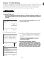
1
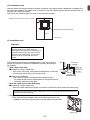
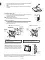
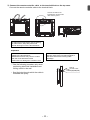
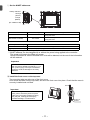
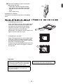
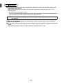
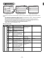
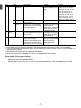
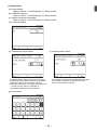
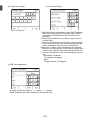
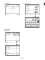
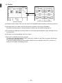
English
CITY MULTI Control System
Smart ME Controller PAR-U02MEDA
Installation Manual
For distribution to dealers and contractors
Prior to use, thoroughly read the instructions in this manual to use the product correctly.
Retain this manual for future reference.
Make sure that the CD-ROM, this manual, and Simple Operation Manual are passed on to
any future users.
To ensure safety and proper operation of the remote controller, the remote controller should
only be installed by qualified personnel.
Chapter 1. Installation
This installation manual describes how to install the Smart ME Controller for use with Mitsubishi
Building Air Conditioning System, direct expansion type CITY MULTI air conditioner indoor units (“-A”
type and later).
Please be sure to read this installation manual and Instruction Book that are supplied with the Remote
Controller before proceeding with the installation. Failure to follow the instructions may result in
equipment damage.
For information on how to wire and install the air conditioning units, refer to the Air Conditioner
Installation Manual.
After the installation, hand over this manual to users.
Smart ME Controller is a type of ME Remote Controllers, sometimes simply referred to as ME Remote
Controller.
1
Safety Precautions
• Read the following safety precautions prior to installation.
• Observe these precautions carefully to ensure safety.
WARNING
Indicates a risk of death or serious injury.
CAUTION
Indicates a risk of serious injury or structural damage.
• After reading this manual, pass it on to the end user to retain for future reference.
• Keep this manual for future reference and refer to it as necessary. This manual should be made
available to those who repair or relocate the controller. Make sure that the manual is passed on to
any future users.
All electric work must be performed by qualified personnel.
General precautions
WARNING
Do not install the unit in a place where large amounts of
oil, steam, organic solvents, or corrosive gases, such
as sulfuric gas, are present or where acidic/alkaline
solutions or sprays are used frequently. These
substances can compromise the performance of the
unit or cause certain components of the unit to corrode,
which can result in electric shock, malfunctions,
smoke, or fire.
To reduce the risk of shorting, current leakage, electric
shock, malfunctions, smoke, or fire, do not wash the
controller with water or any other liquid.
To reduce the risk of electric shock, malfunctions,
smoke or fire, do not operate the switches or touch
other electrical parts with wet hands.
To reduce the risk of injury or electric shock, before
spraying a chemical around the controller, stop the
operation and cover the controller.
To reduce the risk of injury or electric shock, stop the
operation and switch off the power supply before
cleaning, maintaining, or inspecting the controller.
Properly install all required covers to keep moisture
and dust out of the controller. Dust accumulation and
water can cause electric shock, smoke, or fire.
To reduce the risk of injury, keep children away while
installing, inspecting, or repairing the controller.
–1–
CAUTION
To reduce the risk of fire or explosion, do not place
flammable materials or use flammable sprays around
the controller.
To avoid injury from broken glass, do not apply
excessive force on the glass parts.
To reduce the risk of damage to the controller, do not
directly spray insecticide or other flammable sprays on
the controller.
To reduce the risk of injury, wear protective gear when
working on the controller.
Do not directly stare at the LED light, as this may
damage your eyes.
To reduce the risk of electric shock or malfunctions, do
not touch the touch panel with a pointy or sharp object.
To reduce the risk of injury and electric shock, avoid
contact with sharp edges of certain parts.
Precautions during installation
WARNING
Do not install the controller where there is a risk of
leaking flammable gas. If flammable gas accumulates
around the controller, it may ignite and cause a fire or
explosion.
Take appropriate safety measures against earthquakes
to prevent the controller from causing injury.
To prevent injury, install the controller on a flat surface
strong enough to support its weight.
Properly dispose of the packing materials. Plastic bags
pose suffocation hazard to children.
CAUTION
To reduce the risk of shorting, current leakage, electric
shock, malfunctions, smoke, or fire, do not install the
controller in a place exposed to water or in a
condensing environment.
Controller must be installed by qualified personnel
according to the instructions detailed in the Installation
Manual.
Improper installation may result in electric shock or fire.
When attaching the cover and the top casing to the
bottom casing, push it until it they click into place. If
they are not properly locked into place, they may fall,
causing personal injury, controller damage, or
malfunctions.
Precautions during wiring
WARNING
To reduce the risk of damage to the controller,
malfunctions, smoke, or fire, do not connect the power
cable to the signal terminal block.
Properly secure the cables in place and provide
adequate slack in the cables so as not to stress the
terminals. Improperly connected cables may break,
overheat, and cause smoke or fire.
All electric work must be performed by a qualified
electrician according to the local regulations,
standards, and the instructions detailed in the
Installation Manual. Capacity shortage to the power
supply circuit or improper installation may result in
malfunction, electric shock, smoke, or fire.
To reduce the risk of current leakage, overheating,
smoke, or fire, use properly rated cables with adequate
current carrying capacity.
To reduce the risk of injury or electric shock, switch off
the main power before performing electrical work.
CAUTION
To reduce the risk of electric shock, shorting, or
malfunctions, keep wire pieces and sheath shavings
out of the terminal block.
To reduce the risk of electric shock, malfunctions, or
fire, seal the gap between the cables and cable access
holes with putty.
To reduce the risk of shorting, current leakage, electric
shock, or malfunctions, keep the cables out of contact
with controller edges.
–2–
Precautions for moving or repairing the controller
WARNING
The controller should be repaired or moved only by
qualified personnel.
Do not disassemble or modify the controller.
Improper installation or repair may cause injury, electric
shock, or fire.
CAUTION
To reduce the risk of shorting, electric shock, fire, or
malfunction, do not touch the circuit board with tools or
with your hands, and do not allow dust to accumulate
on the circuit board.
Additional precautions
To avoid damage to the controller, use appropriate
tools to install, inspect, or repair the controller.
To avoid discoloration, do not use benzene, thinner, or
chemical rag to clean the controller. To clean the
controller, wipe with a soft cloth soaked in water with
mild detergent, wipe off the detergent with a wet cloth,
and wipe off water with a dry cloth.
This controller is designed for exclusive use with the
Building Management System by Mitsubishi Electric.
The use of this controller for with other systems or for
other purposes may cause malfunctions.
To avoid damage to the controller, provide protection
against static electricity.
Take appropriate measures against electrical noise
interference when installing the air conditioners in
hospitals or facilities with radio communication
capabilities. Inverter, high-frequency medical, or
wireless communication equipment as well as power
generators may cause the air conditioning system to
malfunction. Air conditioning system may also
adversely affect the operation of these types of
equipment by creating electrical noise.
Do not use solderless terminals to connect cables to
the terminal block.
Solderless terminals may come in contact with the
circuit board and cause malfunctions or damage the
controller cover.
To avoid damage to the controller, do not make holes
on the controller cover.
To avoid malfunctions, do not bundle power cables and
signal cables together, or place them in the same
metallic conduit.
To prevent malfunctions, do not remove the protective
film or the circuit board from the casing.
Do not install the controller on the control panel door.
Vibrations or shocks to the controller may damage the
controller or cause the controller to fall.
To avoid damage to the controller, do not overtighten
the screws.
Use a flat-head screwdriver with a blade width of 4-5.5 mm
(5/32-7/32 in). The use of a screwdriver with a narrower or
wider blade tip may damage the controller casing.
To prevent damage to the controller casing, do not
force the driver to turn with its tip inserted in the slot.
To avoid deformation and malfunction, do not install
the remote controller in direct sunlight or where the
ambient temperature may exceed 40ºC (104ºF) or
drop below 0ºC (32ºF).
Hold the cables in place with clamps to prevent undue
force from being applied to the terminal block and
causing cable breakage.
To prevent cable breakage and malfunctions, do not
hang the top controller casing hang by the cable.
The CD-ROM that is supplied with Smart ME Controller
WARNING
The CD-ROM can only be played on a CD-drive or a DVD-drive. Do not attempt to play the
CD-ROM on an audio CD player as this may damage your ears and/or speakers.
The CD-ROM that is supplied with the Smart ME Controller contains an Installation Manual and
Instruction Book.
Each document is in PDF format.
Viewing documents requires a computer with Adobe® Reader® or Adobe® Acrobat® installed.
“Adobe® Reader®” and “Adobe® Acrobat®” are registered trademarks of Adobe Systems Incorporated.
–3–
2
Component names and supplied parts
The following parts are included in the box.
Parts name
Qty.
Remote controller (front cover) *1
1
Remote controller (top case) *1
1
Remote controller (bottom case)
1
Roundhead cross slot screws M4×30 *2
4
Wood screw 4.1×16 *2
(for direct wall installation)
4
Installation Manual (this manual)
1
Simple Operation Manual
1
CD-ROM
(Installation Manual, Instruction Book)
1
Front cover
Top case
Bottom case
*1 The front cover is already installed on the top case at
factory shipment.
*2 ISO metric screw thread
*3 Remote controller cable is not included.
3
Field-supplied parts/Required tools
(1) Field-supplied parts
Parts name
Qty.
Double switch box
1
Thin metal conduit
As needed
Locknut and bushing
As needed
Cable cover
As needed
Putty
As needed
Molly anchor
As needed
Remote controller cable
(0.3 mm² (AWG 22) 2-core
sheathed cable)
As needed
Notes
Not required for direct wall installation
Required for routing remote controller cable along a wall
If the remote controller cable exceeds 10 m (32 ft), use an
electric wire that meets the following specification.
CVVS: 1.25 mm2 (standard AWG 16) or equivalent
CPEVS: ø1.2 mm (standard AWG 16) or equivalent
(2) Required tools
• Flat-tip screwdriver (Width: 4-5.5 mm (5/32-7/32 in))
• Knife or nipper
• Miscellaneous tools
–4–
4
System diagram
Group 01
Outdoor unit
Indoor unit
051
TB7
002
TB5
TB5
101
Smart ME
Controller *1
004
TB5
LOSSNAY unit
005
TB5
102
104
Smart ME
Controller
Smart ME
Controller
Indoor unit
Indoor unit
056
009
TB3
000
CENTRALIZED CONTROLLER AG-150A
Centralized
controller
003
Group 04
Outdoor unit
TB7
Indoor unit
Indoor unit
Indoor unit
001
TB3
Group 03
Group 02
Power supply
unit
Indoor unit
008
TB5
TB5
107
157
Smart ME
Controller
Smart ME
Controller
Indoor unit
007
Advanced HVAC
CONTROLLER (AHC)
006
TB5
201
TB5
*1 The power consumption coefticient of the Smart ME Controller is “0.5” and that of a ME Remote Controller
(PAR-F27MEA) is “0.25”.
If the number of Smart ME Controllers is high and the total power supply they require exceeds the outdoor unit's
ability to supply power, a Transmission booster (PAC-SF46EPA) will be required.
Outdoor unit
Transmission booster
Indoor unit
Smart ME Controller
32
25
1 (*1)
0.5
*1: "7" for the P200 and P250 models
(1) Wiring from the remote controller
• Connect to TB5 (terminal block for indoor-outdoor transmission cable) on any indoor unit in same
M-NET system.
• The terminal block has no polarity. Connect to the terminals M1 and M2.
(2) Operating in a group (Groups 01, 02, 03, and 04)
• Assign the lowest address to the main indoor unit in the group.
The remote controller address should be set to a number that equals the main indoor unit address
plus 100.
(3) Up to two remote controllers (main and sub) can be connected to an indoor unit or a group of
indoor units.
• Connect the main and sub remote controllers in the same way as described in (1) above.
• Be sure to set the main and sub remote controller addresses.
The sub remote controller address should be set to a number that equals the main indoor unit
address plus 150.
- Remote controllers cannot be wired together. Only one
cable can be connected to the remote controller terminal
CAUTION
block.
- The ME remote controller and MA remote controller
cannot be connected in the same group.
–5–
Main
remote
controller
Sub
remote
controller
5
How To Install
This remote controller is for the wall installation. It can be installed either in the switch box or directly
on the wall. When performing direct wall installation, cables can be thread through either back or top
of the remote controller.
(1) Selecting an installation site
Install the remote controller (switch box) on the site where the following conditions are met.
(a) A flat surface
(b) A place where the remote controller can measure the accurate room temperature and humidity
Sensors to monitor the room temperature are on the indoor unit and on the remote controller.
When the room temperature is monitored with the sensor on the remote controller, the main
remote controller monitors the room temperature. When using the sensor on the remote controller,
follow the instructions below.
• To monitor the accurate room temperature and humidity, install the remote controller away from
direct sunlight, heat sources, and the supply air outlet of the air conditioner.
• Install the remote controller in a location that allows the sensor to measure the representative
room temperature and humidity.
• Install the remote controller where no wires are routed around the temperature sensor on the
controller or where no obstacles block the air inlet, otherwise the sensor cannot measure accurate
room temperature and humidity.
• After the controller has been exposed to high humidity (above 80%RH) for 60 hours, the humidity
detection value will be offset by 3%RH.
When the ambient humidity drops below 80%RH, the offset will be gradually cancelled.
• Do not install the controller where it is exposed to high concentration of acid, alkaline, or volatile
organic compounds.
• If exposed to cigarette smoke for a long time, the humidity detection value will be offset.
(c) Install the remote controller where occupancy and brightness can be properly detected.
The remote controller has an occupancy sensor and a brightness sensor.
Each sensor has a sensor-detection zone.
• Install the remote controller where the coverage area covers the appropriate area in the room.
The maximum distance the sensor can detect occupancy is approximately 10 m (32 ft).
Occupancy sensor
Horizontal direction
Vertical direction
Wall
Remote
controller
110°
10
m
11°
Wall
Remote
controller
31°
20°
10 m
Floor
Figure 2
Figure 1
: Detection area
* As an inherent characteristic of the occupancy sensor, it is more sensitive to movements across
the area indicated by ■ than to movements straight toward the sensor.
–6–
Occupancy sensor detects occupancy based on the temperature difference between the occupant
and its surroundings.
To be precise, to enhance the sensitivity of the sensor to occupant movements, the occupancy
sensor is designed to detect the changes in the amount of infrared light emitted from an object in
the detection zone, including human bodies.
The occupancy sensor will not detect occupancy if no movements exist.
The sensor also becomes less sensitive to occupancy when the temperature difference between
the occupant and its surroundings is small.
• Select the installation location carefully to avoid false detection.
Factors that contribute to false detection by the occupancy sensor
• Direct sunlight to the remote controller
• Supply air directed straight toward the remote controller
• Fireplace in the detection zone
• Portable heater (e.g., oscillating electric heater) in the detection zone
• Excessive vibrations or large impact inflicted on the remote controller
• Strong electrical noise
• Movements of small animals, such as cats and dogs
Brightness sensor
Horizontal direction
Vertical direction
Wall
Remote
controller
Wall
44°
22°
Remote
controller
44°
22°
Figure 3
Floor
Figure 4
Handling precautions
• Keep the lens scratch-free.
• Do not place adhesive tape or labels over the lens.
• Use a soft cloth to clean the lens.
Important
Do not install the controller in a place where
the difference between the remote controller
surface temperature and the actual room
temperature will be great.
If the temperature difference is too high,
room temperature may not be adequately
controlled.
To reduce the risk of malfunctions, do not
install the controller in a place where water
or oil may come into contact with the
controller, or in a condensing or corrosive
environments.
Do not install the remote controller directly
onto electrically conductive objects such as
metal plate that has not been painted.
To avoid deformation and malfunction, do
not install the remote controller in direct
sunlight, where the ambient temperature
may rise above 40ºC (104°F) or drop below
0ºC (32°F), or where the relative humidity
may rise above 90% or drops below 20%.
To use the Energy Saving Assist function in
a system with both main and sub remote
controllers, activate the function only on the
remote controller whose coverage area is
the largest.
–7–
(2) Installation space
Leave a space around the remote controller as shown in the figure below, regardless of whether the
controller is installed in the switch box or directly on the wall. Removing the remote controller will not
be easy with insufficient space.
Also, leave an operating space in front of the remote controller.
Required space around the remote controller
30 (1-3/16)
30
(1-3/16)
30
(1-3/16)
Temperature and Humidity sensor
120 (4-3/4)
unit: mm (in)
(3) Installation work
Important
Use caution when handling circuit boards to
prevent damage from static electricity.
Although the circuit board is covered with an
insulation sheet, part of the circuit board is
exposed. Use extra caution not to let your
fingers come in contact with the circuit
board.
The remote controller can be installed either in the switch box or
directly on the wall. Perform the installation properly according to
the method.
1 Drill a hole in the wall.
■ Installation using a switch box
• Drill a hole in the wall, and install the switch box on the wall.
• Connect the switch box to the conduit tube.
Wall
Conduit tube
Locknut
Switch box
Bushing
Seal the gap
with putty.
Remote
controller cable
■ Direct wall installation
• Drill a hole in the wall, and thread the cable through it.
* No cable access hole is required when running the remote
controller cable along the wall.
2 Seal the cable access hole with putty.
■ Installation using a switch box
• Seal the cable access hole at the connection of switch box and conduit tube with putty.
To reduce the risk of electric shock, malfunctions, or fire, seal the gap between the cables and
cable access holes with putty.
3 Prepare the bottom case of the remote controller.
* Take the following procedure only when performing direct wall
installation and running the remote controller cable along the wall.
Bottom case
–8–
• Cut out the thin-wall part on the cover (indicated with the shaded
area in the right figure) with a knife or a nipper.
Note:
Make sure that the hole edges are smooth and will not damage
the wires.
4 Install the bottom case.
• Remove the sheath as shown in the figure at right, and route the
remote controller cable behind the bottom case.
Install the bottom case.
Sheath
■ Installation using a switch box
• Secure at least two corners of the switch box with screws.
60 (2-3/8)
6 (1/4)
■ Direct wall installation
• Secure at least two corners of the remote controller with screws.
• Be sure to secure top-left and bottom-right corners of the remote
controller (viewed from the front) to prevent it from lifting.
(Use molly anchor etc.)
■ Installation using a switch box
Double switch box
Roundhead
cross slot
screws
Unit: mm (in)
■ Direct wall installation
Seal the cable
access hole
with putty.
Refer to 2.
Remote
controller
cable
Wood
screws
Remote
controller
cable
Important
To avoid damage to the controller, do not
overtighten the screws.
To avoid damage to the controller, do not
make holes on the controller cover.
5 Install the top case on the bottom case.
Two mounting tabs are at the top of the top
case.
Hook those two tabs onto the bottom case,
and click the top case into place. Check that
the case is securely installed and not lifted.
Wall
Should not
be lifted
* The controller is shipped with the front cover mounted to the top case.
Remove the front cover from the top case before installing the top case on the wall.
Refer to “1 Uninstalling the front cover” on page 12.
–9–
6 Connect the remote controller cable to the terminal block on the top case.
Connect the remote controller cable to the terminal block.
Connect the cable to the
terminal block, and insert the
cable into the groove.
To reduce the risk of electric shock, shorting,
or malfunctions, keep wire pieces and
sheath shavings out of the terminal block.
Important
Do not use solderless terminals to connect
cables to the terminal block.
Solderless terminals may come in contact
with the circuit board and cause
malfunctions or damage the controller cover.
Hold the cables in place with clamps to
prevent undue force from being applied to
the terminal block and causing cable
breakage.
* Take the following procedure only when
performing direct wall installation and
drilling a hole in the wall.
• Seal the hole through which the cable is
threaded with putty.
– 10 –
Remote
controller cable
Seal the gap with putty.
7 Set the M-NET addresses.
Rotary switches
78
456
78
9 01
23
456
1's digit
(Below)
9 01
23
10's digit
(Above)
(Ex: Address 108)
Address range
Main remote controller
101 to 150
Sub remote controller
151 to 200
Rotary switch setting
01 to 99
00
Address setting method
Address that equals the lowest address of the
group plus 100
Address that equals the lowest address of the
group plus 150
Address
101-199 with the 100's digit automatically set to 1
200
* The factory setting for the rotary switches is 01.
** M-NET address can be changed with or without the power being applied to the controller.
The screen will jump to the [Start-up] screen.
Group information for indoor units and AHC units will be deleted, but the rest of the information
will be retained.
Important
To set the address, turn the rotary switch
with a precision slotted screwdriver [(-), 2.0
mm (1/16 in) (W)] to a torque of less than
19.6 N to avoid the damage to the rotary
switches.
8 Install the front cover on the top case.
Two mounting tabs are at the top of the front cover.
Hook those two tabs onto the top case, and click the front cover into place. Check that the case is
securely installed and not lifted.
Wall
Important
When attaching the front cover to the top
case, push it until it they click into place.
If they are not properly locked into place,
they may fall, causing personal injury,
controller damage, or malfunctions.
Should not
be lifted
– 11 –
■ Direct wall installation (when running the
cable along the wall)
• Thread the cable through the access
hole at the top of the remote controller.
• Seal the cut-out part of the cover with
putty.
• Use a cable cover.
Putty
Installation is complete.
Follow the instructions below when uninstalling
them.
• Uninstalling the front cover and top case
1 Uninstalling the front cover
Insert a flat-tip screwdriver (with a blade width
of 5.5 mm (7/32 in) or less) into either of the
two latches at the bottom of the remote
controller as shown in the figure at right.
Lightly push the tip of the flat-head
screwdriver in the direction of the arrow in the
figure to remove the front cover.
Lightly push
the tip in.
2 Uninstalling the top case
Insert a flat-tip screwdriver (with a blade width
of 5.5 mm (7/32 in) or less) into either of the
two latches at the front of the remote controller
as shown in the figure at right.
Push the tip of the flat-head screwdriver in the
direction of the arrow in the figure to remove
the top case.
Important
Use a flat-head screwdriver with a blade
width of 4-5.5 mm (5/32-7/32 in). The use of
a screwdriver with a narrower or wider blade
tip may damage the controller casing.
To prevent damage to the control board, do
not insert the driver into the slot strongly.
To prevent damage to the controller casing,
do not force the driver to turn with its tip
inserted in the slot.
– 12 –
6
Important
■ Discrepancy between the room temperature measured at the wall and the actual room
temperature may occur.
If the following conditions are met, the use of the temperature sensor on the indoor unit is
recommended.
• Air distribution in the space is poor.
• There is a great discrepancy between the wall temperature and the actual room temperature.
• The back side of the wall is directly exposed to the outside air.
NOTE: When temperature changes rapidly, the temperature may not be detected
accurately.
■ Refer to the following manual for temperature sensor setting: indoor unit Installation
Manual for City Multi.
■ At the time of factory shipment, protective sheet is on the operation interface of the front
cover.
Peel off the protective sheet on the operation interface prior to use.
– 13 –
Chapter 2. Initial Setting
This chapter contains information about the settings to be made at the time of installation. Please read
the instructions carefully and make the settings accordingly. Refer to Chapter 1 “Installation” for how to
install the Remote Controller, and refer to the air conditioning unit installation manuals for how to
connect the controller cable to the air conditioning units, or how to install the air conditioning units.
Please remember to give all manuals to the end users after installation is complete.
1
Initial Settings
(1) Initial startup settings
Before turning on the controller, first make sure that the controller, indoor units, and outdoor units
have been installed properly according to the instructions detailed in the respective manuals. Turn on
the controller and the units.
• This manual is intended for the first startup after the unit has been shipped from the factory. If the
setting has been changed even once, the popup window or setting screens explained below may
not appear.
(a) The Language screen will appear.
1Touch the button to select the language of your choice.
2 Touch the [Done] button.
(b) The Start-up screen will appear.
[Case 1] Basic setup (including the setup performed at
the time of system controller connection)
The screen will automatically jump to the HOME screen
after a while.
Change the initial settings information as necessary.
(Refer to section 2 “Service Menu.”)
*This screen will not appear if the Basic setup has
already been completed.
[Case 2] Manual setup from the controller
Touch the [Setup] button to access the [Setup] screen.
When done making the settings for the "Group setting" and
"Interlocked LOSSNAY," touch [Back] to startup the system
and return to the Home screen. It may take about 7 minutes
until the screen [General equipment] becomes accessible.
– 14 –
(2) Setup screen
(a) Group setting
Use this screen to register the indoor units and the AHC to be controlled from the controller.
1 Select an indoor unit or an AHC address in the
[Address] field.
The number of units that can be registered.
Indoor unit: 16 units maximum
AHC: 1 unit maximum
* AHC cannot be controlled from the controller unless indoor
units are registered with the system.
2 Touch the [Set] button to register the address, and
[Del] to delete the address.
• Successful address registration/deletion:
The registered address(es) will appear on the left
side of the screen.
Deleted address will not appear on the screen.
• Error:
"Request denied." or "Is not to be connected" will
appear.
(b) Interlocked LOSSNAY
Use this function to interlock the operation of indoor units and LOSSNAY units.
1 To register LOSSNAY units
Select the indoor unit address in the Add. 1 section.
Select the interlocked LOSSNAY address in the Add. 2
section. Touch the [Set] button to save the setting.
2 To search for an interlocked setting
Touch the [Conf] button to display in the left column
the addresses of the units that are interlocked with the
unit whose address was set in the Add. 1 section.
3 To delete the interlock settings
After taking Step 2 above, select the address to be
deleted in the Add. 2 section, and then touch the [Del]
button.
When the setting or deletion is successfully completed, “Completed” will appear below
[Function] field on the screen.
If setting or deletion fails, “Request denied” will appear below [Function] field on the screen.
(c) Search connection information
Use this screen to specify a unit and search for the controllers that are connected to the unit.
1 Select an address in the [Address] field.
2 Touch the [Conf] button to search for the interlocked
units.
The results will appear in the left column. (When
multiple units are found, the addresses that do not fit
on the first page will appear on the successive pages.)
• Search error:
"Request denied." will appear.
After completing the settings, touch the [Back] button on the [Setup] screen. The message “Collecting
the information from the air conditioner.” will appear, and then the screen will jump to the HOME screen.
This signals the completion of the setup process.
Access the Service Menu from the HOME screen to make the settings for other items as necessary.
– 15 –
2
Service Menu
[HOME screen]
[Menu (User) screen]
[Menu (Service) screen]
A password is required to access the Menu (Service) screen or some settings under the Menu (User)
screen.
• The initial Service password is “9999.” The initial User password is “0000.” Change the password
as necessary to prevent unauthorized access.
• Make sure the password is available to the maintenance and other necessary personnel.
• The password can be changed to any four-digit number. On the [Login page], enter the old
password, touch the [Change] button, and then enter a new password.
• If you forget your password, log in with the master password.
Master service and user password: 1056
■Service menu items
Item
Detail
(1) Setup (a) Group
setting
(b) Interlocked
LOSSNAY
Description
Make the group setting for the
indoor units, and an AHC
Enters the interlock settings
between indoor and LOSSNAY
units
(c) Search
Use to search and display the
connection
units that are connected to a
information
specified unit.
(d) Cool/Heat
Use to show or hide the
display
operation mode signs (Cool/
Heat) on the HOME screen
while the units are operated in
the Auto mode.
(e) Temperature Use to offset the reading on the
sensor offset built-in temperature sensor. *1
Setting
Refer to section 1
"Initial Settings" (2)
"Setup screen".
Default
–
Select between Show/
Hide.
Auto: Show
Set the offset value.
(-5ºC~+5ºC)
(-10ºF~+10ºF)
(f) Humidity
Use to offset the reading on the Set the offset value.
sensor offset built-in humidity sensor.
(-10%~+10%)
(g) Room name Use to enter room names (max. Use a combination of
16 characters). The names
capital letters, smallentered here will appear on the case letters, numerical
HOME screen.
characters and symbols.
(h) Telephone
Use to enter the telephone
Use numerical
number
number of the maintenance
characters and
personnel (max. 13 numbers). hyphens.
This number will be displayed
on the screen that appears
when an error occurs.
(i) IC function
Use to make the settings for the To be explained later
setting
indoor units from the controller.
* Refer to the indoor unit installation
manual for the detailed
explanation of the setting items.
– 16 –
Offset: 0.0ºC (0ºF)
Offset: 0%
Blank
Blank
–
Item
Detail
(1) Setup (j) LED color
adjustment
(k) Reset RC
(l)
AHC port
name *4
(2) Error (a) Self check
menu
(3) Test run
Description
Setting
Adjusts the LED indicator color. Sets the R (Red), G
*2 (Green), B (Blue) color
ratio.
Default
Blue: R, G, B=0, 0, 100
L.Blue: R, G, B=0, 40, 60
Purple: R, G, B=40, 0, 100
Red: R, G, B=100, 0, 0
Pink: R, G, B=80, 20, 40
Orange: R, G, B=100, 40, 0
Yellow: R, G, B=60, 80, 0
Green: R, G, B=0, 100, 0
Lime: R, G, B=40, 100, 0
White: R, G, B=80, 100, 40
Use to initialize the memory on Touch the Reset button. –
the controller. *3
Use to customize the AHC port Set button: Jumps the Blank
names (max. 20 characters).
screen to the AHC port
These names can be reset to
renamed screen.
the default names.
Reset button: Changes
all the port names to
the default names.
Use to check the error history of Sets the monitor targets –
the desired unit and to reset the and displays error history.
Reset button: Deletes
error history.
the error history.
Use to test the air conditioning Test-run
–
units. (Except AHC)
Displays the liquid pipe
Liquid pipe temperature of
temperature of the
indoor unit will appear during
indoor unit at the
the test run. The test-run will
specified address.
automatically end in two hours.
*1 This setting will not become effective if the temperature sensor on the indoor unit is activated.
*2 The LED indicates the operation status of air conditioning units in colors. Refer to "LED Indicator" in
the instructions book.
*3 All settings information will be cleared to the default.
*4 AHC port name will not appear if no AHC unit is registered in the group.
[Data backup during power failure]
All the data for items except items (1)-(k) Reset RC and (3) Test run are nonvolatile, and will be
backed up even during power failure.
Data for items (1)-(a), (b), (c), (i), and (2)-(a) will be backed up on the air conditioning unit side.
– 17 –
(1) Setup menu
(a) Group setting
Refer to section 1 "Initial Settings" (2) "Setup screen".
(b) LOSSNAY interlock
Refer to section 1 "Initial Settings" (2) "Setup screen".
(c) Search connection information
Refer to section 1 "Initial Settings" (2) "Setup screen".
(d) Cool/Heat display
(e) Temperature sensor offset
(f) Humidity sensor offset
* The temperature in the [Current room temp.] field
indicates the temperature measured by the built-in
temperature sensor on the remote controller.
** When the offset value is changed, it may take up to
1 minute until the change is reflected on
temperature display on the Home screen.
* The humidity in the [Current humidity] field indicates
the humidity measured by the built-in humidity
sensor on the remote controller.
(g) Room name
(max. 16 characters)
– 18 –
(h) Telephone number
(max. 13 numbers)
(i) IC function setting
1Select the indoor unit address in the [M-NET address]
field. (When [Grp] has been selected, all the indoor
units that are controlled from the controller will be
selected.)
2Select the desired function number in the [Function
number] field.
3Touch the [Conf] button to confirm the current settings.
Indoor units will acquire the current settings, and the
results will appear in the [Function setting] field.
4Select the number* that corresponds to the desired
function to be configured in the [Function setting] field.
* Refer to the manuals that came with the indoor unit.
5Touch the [Set] button to save the setting to the indoor
unit.
•Successful completion:
"Completed" will appear.
•Error:
"Request denied." will appear.
(j) LED color adjustment
R (Red), G (Green), B (Blue): “+”···Darken, “–”···Lighten
Reset: Restores the default settings for the display color.
– 19 –
(k) Reset RC
(l) AHC port name
(max. 20 characters)
(2) Error Menu
(a) Self check
– 20 –
(3) Test Run
[Indoor unit setting screen]
[Test run screen]
(a) Read the section about Test run in the indoor unit Installation Manual before performing a test run.
(b) During the test run, indoor units will be forced to operate in the Thermo-ON status.
Except the set temperature, normal operation functions are accessible during test run.
(c) By selecting the address of another indoor unit, the liquid pipe temperature of the selected unit can
be monitored.
(d) The test run will automatically end in two hours.
* When AHC is controlled from the controller
To monitor the operating status of AHC, touch the [<] button on the [Test run] screen and access
the [General equipment] screen.
To set the humidity setting for the humidifier (when one is connected to the AHC), touch the [>]
button on the [Indoor unit setting] screen.
– 21 –
Specifications
Receives power from outdoor units via the M-NET
17-32 VDC *1
transmission cable. The power consumption
(for connection to M-NET only)
coefficient*2 of the Smart ME Controller is “0.5”.
Power Source
Operating conditions
Temperature
Humidity
Weight
External dimensions (W x H x D)
Operating temperature range
0ºC – +40ºC (+32ºF – +104ºF)
Storage temperature range
-20ºC – +60ºC (-4ºF – +140ºF)
20%–90% RH (Non-condensing)
0.3 kg (11/16 lbs)
140 x 120 (123) x 25 (28.8) mm
5-17/32 x 4-3/4 (4-27/32) x 1 (1-5/32) in
* The numbers in the parenthesis indicate the dimensions including the protruding
parts.
*1 Not for use with a generic DC power supply device.
*2 “Power consumption coefficient” is a coefficient to calculate the relative power consumption of the
devices that receive power through the M-NET transmission cable.
Refer to section 4 “System diagram” in Chapter 1 in this Manual.
Note:
This equipment has been tested and found to comply with the limits for a Class B digital device, pursuant to Part 15
of the FCC Rules. These limits are designed to provide reasonable protection against harmful interference in a
residential installation. This equipment generates, uses and can radiate radio frequency energy and, if not installed
and used in accordance with the instructions, may cause harmful interference to radio communications.
However, there is no guarantee that interference will not occur in a particular installation.
If this equipment does cause harmful interference to radio or television reception, which can be determined by
turning the equipment off and on, the user is encouraged to try to correct the interference by one or more of the
following measures:
- Reorient or relocate the receiving antenna.
- Increase the separation between the equipment and receiver.
- Connect the equipment into an outlet on a circuit different from that to which the receiver is connected.
- Consult the dealer or an experienced radio/TV technician for help.
– 22 –
This product is designed and intended for use in the residential,
commercial and light-industrial environment.
The product at hand is based on the following EU regulations:
• Electromagnetic Compatibility Directive 2004/108/EC
• Restriction of Hazardous Substances 2011/65/EU
Please be sure to put the contact address/telephone number on
this manual before handing it to the customer.
HEAD OFFICE: TOKYO BLDG., 2-7-3, MARUNOUCHI, CHIYODA-KU, TOKYO 100-8310, JAPAN
Authorized representative in EU: MITSUBISHI ELECTRIC EUROPE B.V.
HARMAN HOUSE, 1 GEORGE STREET, UXBRIDGE, MIDDLESEX UB8 1QQ, U.K.