1
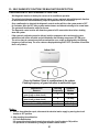
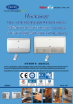
R22 220-240V ~ 50Hz 1Ph Harmony Floor / Under Ceiling Split Air Conditioners 53VMCT 18C-24C Cool Only 53VMCT 18H-24H Heat Pump INSTALLATION MANUAL Carrier is committed to continuously improving its products according to national and international standards to ensure the highest quality and reliability standards, and to meet market regulations and requirements. All specifications subject to change without prior notice according to Carrier policy of continuous development. 03502827 Quality Management System ISO 9001 : 2008 Certificate No.: QS-5519HH Enviromental Management System ISO 14001 : 2004 Certificate No : 12 104 30334 TMS Safety Management System BS OHSAS 18001 : 2007 Certificate No : 12 116 30334 TMS Rev. (0) - 2013 TABLE OF CONTENTS PAGE NO. 1. GENERAL NOTES TO INSTALLER 1 2. PRECAUTIONS BEFORE INSTALLATION 2 3. SPLIT SYSTEM DESCRIPTION 3 4. MODELS 4 5. OPERATING LIMITS 4 6. DIMENSIONS AND WEIGHTS OF INDOOR UNIT 5 7. DIMENSIONS AND WEIGHTS OF OUTDOOR UNIT 5 8. SELECTING INSTALLATION LOCATION OF INDOOR UNIT 6 9. SELECTING INSTALLATION LOCATION OF OUTDOOR UNIT 8 10. INSTALLATION LOCATION – CHECK LIST 12 11. INSTALLTION ACCESSORIES 13 12. INSTALLATION CHART 15 13. INDOOR UNIT INSTALLATION 16 13.1 PREPARING UNIT BEFORE INSTALLATION 16 13.2 INSTALLATION STEPS 17 14. REMOTE CONTROL INSTALLATION 20 15. OUTDOOR UNIT INSTALLATION 15.1 PREPARING UNIT BEFORE INSTALLATION 22 15.2 INSTALLATION STEPS 22 16. CONNECTING REFRIGERANT PIPING LINES 23 17. CONNECTING CONDENSATE DRAIN LINE 38 18. CONNECTING ELECTRICAL WIRING 39 19. FINISHING INSTALLATION 45 20. TEST RUNNING 46 21. SUPPLY AIR CONTROL OF INDOOR UNIT 48 22. AFTER INSTALLATION CHECK LIST 49 23. SELF DIAGNOSTIC FUNCTION FOR MALFUNCTIONS DETECTION 51 1. GENERAL NOTES TO INSTALLER CARRIER split room air conditioner has been carefully designed and manufactured under strict Quality Control conditions. Therefore you are completely responsible for proper installation completion and operation of the air conditioner. Carefully read the manual carefully before proceeding with the installation to ensure correct installation. This manual describes installation instructions to help ensure trouble free operation and extended life of the air conditioner. Make sure all accessory parts are with the system before beginning installation. You will need the following tools during installation: 1. 2. 3. 4. 5. 6. 7. 8. 9. Standard screw driver Phillips head screw driver Hole core drill Tape measure Water level Pipe clamp Pipe cutter Spanner Reamer 10. 11. 12. 13. 14. 15. 16. 17. 18. Flare tool set Pipe bender Hexagonal wrench Torque wrench Vacuum pump Gas leak detector Manifold gauge Thermometer Electrical circuit tester After completion of installation, perform a run test and give the customer full instructions on the correct operation of the air conditioner including: • Turning the unit on and off. • Functions of the remote control. • Removal and cleaning of the air filters. • Re-installation of air filters after cleaning Leave the owner manual with the customer so that it can to be used during operation of the air conditioner. Leave the installation manual with the customer so that it can be used for any service and maintenance operations. Advise the customer to the tips of energy saving while operating the air conditioner as mentioned in the owner’s manual. 1 2. PRECAUTIONS BEFORE INSTALLATION SAFETY PRECAUTIONS • Installation and maintenance of air conditioning equipment can be hazardous due to system pressures, electrical components and rotating parts. • The installation and maintenance of the air conditioner must be Carried out by trained and qualified technicians from Carrier or one of Carrier authorized dealers. • After unpacking, Please check carefully for possible damage the indoor and outdoor units of the air conditioner. • Before undertaking any work on the indoor and outdoor units of the air conditioner, make sure to disconnect the power supply. ! WARNING • This installation manual describes the installation procedures of Carrier split room air conditioner consisting of an outdoor unit and an indoor unit manufactured by Carrier. • The installation of air conditioner must be according to applicable national installation standards. During installation, Proceed first with refrigerant connections between indoor and outdoor units, • and only then make the electrical connections. Similarly, when disassembling, disconnect the electrical wiring first and only then open refrigerant connections. What is not covered in Carrier warranty? 1- Failure due to wrong electrical connections between the electrical power supply and circuit breaker of air conditioner leading to fire due to short-circuiting. As these electrical connections are owner’s responsibility. 2- Failure due to Misuse, Abusing, overloading, negligence of air filters cleaning and negligence of instructions included in the owner’s manual. 3- Failure due to Accident / Weather Natural catastrophe, accident due to bad weather (Hail Storm, Sand Storm, lightning, Flooding, Acid Rain and Air Borne fallout, etc). 4- Failure due to damages during transport done through the owner. 5- Failure due to any modifications in the product done through the owner. 6- Failure due to Installation done through the owner. Installation must be done by Carrier or one of Carrier authorized dealers. 7- Failure due to Service and Maintenance done through the owner. Service and maintenance must be done by Carrier or one of Carrier authorized dealers. 8- Failure due to repair by using non-genuine Carrier Parts, or substituting other than Carrier parts done through the owner. All repair works must be done by Carrier or one of Carrier authorized dealers. 9- Product normal sound ( refrigerant – moving parts – plastic parts ) 10- Inconvenience or commercial loss is not covered. The decision of Carrier in ascertaining the same will be final. Any such repairs will be carried out at the expense of the owner ( purchaser ). 2 3. SPLIT SYSTEM DESCRIPTION Indoor Unit 1 2 3 6 7 8 5 4 Outdoor Unit 9 1: Remote control signal receiver 2: Operating status leds 6: Supply air outlet of indoor unit 3: Supply air flap of indoor unit 7: Characteristics nameplate. 4: Air return to indoor unit 8: Refrigerant piping lines and electrical cables 5: Air filters inside indoor unit 9: Condensate drain line. 3 4. MODELS HEAT PUMP COOL ONLY System Model Indoor Unit Model Outdoor Unit Model System Model Indoor Unit Model Outdoor Unit Model 53VMCT18H-708 42VMCT18H-708 38VMCT18H-708 53VMCT18C-708 42VMCT18C-708 38VMCT18C-708 53VMCT24H-708 42VMCT24H-708 38VMCT24H-708 53VMCT24C-708 42VMCT24C-708 38VMCT24C-708 NOTES: 53 42 38 VMC T 18 H C 7 0 8 = Split System = Indoor Unit = Outdoor Unit = Floor / Under Ceiling Harmony Series = High Ambient = System Size = Heat Pump = Cool Only = Nominal Power Supply 220-240V ~ 50Hz 1Ph = Wireless Remote Control = Miraco – Carrier 5. OPERATING LIMITS COOLING Dry Bulb Difference Temp. C° Indoor temperature Maximum 32 Minimum 21 Outdoor temperature Maximum 52 Minimum 21 HEATING Dry Bulb Difference Temp. C° Indoor temperature Maximum 27 Minimum 20 Outdoor temperature Maximum 24 Minimum 2 Wet Bulb Temp. C° 23 15 Wet Bulb Temp. C° 18 1 MAIN POWER SUPPLY Nominal 220-240V ~ 50Hz 1Ph Min. Voltage 198 Max. Voltage 254 NOTES: * When the system operates above or below these limits for a long time, system diagnostics may detect a malfunction and the system will not operate properly. ** During heat pump operation, the system will undergo several defrost cycles to eliminate ice that might possibly collect on the outdoor unit in very low ambient temperatures. After completions of defrost cycle, the system will normally operate 4 6. DIMENSIONS AND WEIGHTS OF INDOOR UNIT Weight Kg Model Kg 42VMCT18 18 42VMCT24 20 1000 200 DIMENSIONS (mm) 598 40 50 7. DIMENSIONS AND WEIGHTS OF OUTDOOR UNIT DIMENSIONS (mm) Mounting Dimensions Model (mm) 38VMCT18 A B 530 290 Unit Dimensions (mm) C D E 760 590 285 Weight D Kg 39.5 C A E B Weight Model 860 350 665 384 Kg Kg 575 38VMCT24 58.7 350 371 665 5 8. SELECTING INSTALLATION LOCATION OF INDOOR UNIT 8.1 CONSIDERATIONS OF SELECTING INSTALLATION LOCATION 500 Select installation location which allows minimum clearances for free air circulation and easy accessibility for service and maintenance. 50 min 50 Ceiling Installation Wall Installation Dimensions (mm) Select installation location so that the wall hole required to pass the outlet refrigerant piping lines, electrical cables and condensate drain line from indoor unit can be in one of the following Four outlet locations as indicated by (1), (2), (3) and (4) NOTE: The recommended outlet location to pass refrigerant piping lines, electrical cables and condensate drain line either from unit right back or from unit left back to keep appearance of installation and to facilitate installation. The unit indoor hides the refrigerant lineselectrical cables and condensate drain line. Avoid installation location which can lead to excessive length of refrigerant piping lines between indoor and outdoor units Avoid installation location which can lead to excessive height difference between indoor and outdoor units 6 SELECTING INSTALLATION LOCATION OF INDOOR UNIT (Cont.) CONSIDERATIONS OF SELECTING INSTALLATION LOCATION (Cont.) Select installation location which permit the unit to deliver air to all of the space to be uniformly air-conditioned. Avoid installation of the indoor unit at too low a position. Avoid installation location which is subjected to direct sun light that may affect performance of the unit Avoid installation location which is near to heat sources that may affect performance of the unit. Avoid installation location where there are obstacles such as curtains and such as curtains, furniture near the air inlet or outlet that may affect air flow and performance of the unit. obstacle Avoid an installation location, which has an environment with oil vapors. Avoid an installation location which has an environment affected by high frequency waves generated as from radio equipment’s welders and medical equipment’s. Select installation location which has flat wall surface to allow easy and safe installation. The wall structure should be strong enough to carry the unit weight and avoid deformation, rupture or vibration during operation. 7 9. SELECTING INSTALLATION LOCATION OF OUTOOR UNIT 9.1 INSTALLATION LOCATIONS The outdoor unit can be installed in any outside location, on a wall, on a roof or on a ground level. 9.2 CONSIDERATIONS FOR SELECTING INSTALLATION LOCATIONS Avoid installation location which can lead to excessive distance between outdoor and indoor units to avoid alteration on system cooling and heating performance. Avoid installation location which can lead to excessive height difference between indoor and outdoor units to avoid alteration on system cooling and heating performance. Avoid installation location which can lead to unnecessary turns and bends in the refrigerant piping lines connecting outdoor unit with indoor unit. Avoid installation location where there are obstacles near the air outlet or inlet that may affect air flow and performance of the unit Avoid multiple unit installation with units facing each other and blowing discharged air into each other. 8 SELECTING INSTALLATION LOCATION OF OUTOOR UNIT (Cont.) CONSIDERATIONS FOR SELECTING INSTALLATION LOCATION (Cont.) Select the installation location of outdoor unit which is able to support operating weight of outdoor unit, and not cause vibration. Select the installation location of outdoor unit which is far away from the direct sunlight. Select the installation location of outdoor unit which is far away from heat sources, steam or flammable gas. Select the installation location of outdoor unit which is free of dust or any material, which can cause clogging of condenser coil. When installing unit on the ground, select a location not subjected to flooding. Avoid installation location which is full of oil vapors which may result in malfunction. Avoid installation location which is full of sulfuric gas which may result in malfunction. Select installation location where the operation noise and discharged air are not disruptive to your neighbors. When the installation is made on the rooftop or other places subject to strong wind : When the outdoor unit is to be installed on the rooftop or at the places where there are no other buildings around. it is required to avoid the strong wind from blowing directly into the air outlet of the outdoor unit so as to prevent the negative impacts on cooling or heating performances due to insufficient airflow of the outdoor unit heat exchanger and to prevent from faulty performances. When there are walls in the vicinity, the air outlet When the air outlet is affected by the strong wind, should face the wall and keep a space of 500mm the installation position should be changed so as from the wall. to make the air outlet at a straight angle from the wind direction. 9 SELECTING INSTALLATION LOCATION OF OUTOOR UNIT (Cont.) 9.3 MINIMUM CLEARANCES WHEN SELECTING INSTALLATION LOCATION FOR SINGLE OUTDOOR UNIT INSTALLATION Obstacle at unit front ( air outlet ) Select installation location which allows the minimum clearances shown in the figures for free air circulation and easy accessibility for service and maintenance : 500 mm or more Obstacle at unit front ( air outlet ) & Obstacle at unit back ( air inlet ) 160 mm or more 1000 mm or more Obstacle at unit front ( air outlet ) & Obstacle at unit top 400 mm or more 1000 mm or more Obstacle at unit back ( air inlet ) 160 mm or more Obstacle at unit back ( air inlet ) & Obstacle at unit top 160mm or more 400mm or more Obstacle at unit back ( air inlet ) & Obstacle at unit right and left sides 160 mm or more 400 mm or more 250 mm or more 10 The front of outdoor unit ( air outlet ) should be away from any obstacle by 500 mm or more to ensure free air circulation. The back of outdoor unit ( air inlet ) should be away from any obstacle by 160 mm or more. This distance is built in the design of wall support to ensure free air circulation. The left side of outdoor unit should by away from any obstacle by 400 mm or more to ensure easy access to refrigerant and electrical connections. The right side of outdoor unit ( air inlet ) should be away from any obstacle by 250 mm or more to ensure free air circulation. The top side of outdoor unit should be away from any obstacle by 400 mm or more to ensure easy access to the electrical components, motor and fan. SELECTING INSTALLATION LOCATION OF OUTOOR UNIT (Cont.) 9.4 MINIMUM CLEARANCES WHEN SELECTING INSTALLATION LOCATION FOR SERIAL INSTALLATION OF MORE THAN ONE OUTDOOR UNIT Obstacle at unit front ( air outlet ) Select installation location which allows the minimum clearances shown in the figures for free air circulation and easy accessibility for service and maintenance : 1000 mm or more Obstacle at unit front ( air outlet ) & Obstacle at unit back ( air inlet ) 160 mm or more 1000 mm or more 400 mm or more 400 mm or more Obstacle at unit back ( air inlet ) 160 mm or more 400 mm or more 400 mm or more Obstacle at unit back ( air inlet ) & Obstacle at right and left sides 160 mm or more 400 mm or more 400 mm or more 400 mm or more 250 mm or more 11 The front of outdoor unit ( air outlet ) should be away from any obstacle by 500 mm or more to ensure free air circulation. The back of outdoor unit ( air inlet ) should be away from any obstacle by 160 mm or more. This distance is built in the design of wall support to ensure free air circulation. The left side of outdoor unit should by away from any obstacle by 400 mm or more to ensure easy access to refrigerant and electrical connections. The right side of outdoor unit ( air inlet ) should be away from any obstacle by 250 mm or more to ensure free air circulation. The top side of outdoor unit should be away from any obstacle by 400 mm or more to ensure easy access to the electrical components, motor and fan. 10. INSTALLATION LOCATION CHECK LIST (A) INDOOR UNIT - The installation location is close to the outdoor unit - The wall hole (required to pass refrigerant piping, electrical cables and drain line) is properly made as per installation required. - The installation location permit the unit to deliver air to all of the space to be air-conditioned - The installation location is far away from any sunlight - The installation location is far away from any heat sources - The installation location avoid obstructions, which affect motion of supply and/or return air to the unit - The installation location permit free service space around the unit right, left, front back and top (B) OUTDOOR UNIT - The electrical power supply is close to the outdoor unit - The installation location is close to the indoor unit - The installation location is able to support operating weight of outdoor unit - The installation location is far away from any sunlight - The installation location is free of dust or any material, which can cause clogging of outdoor coil - The installation location allow sufficient space for air circulation around the unit - The installation location allow sufficient space for service and maintenance around the unit - The installation location is selected so that the operation noise and discharge air do not disturb the neighbors (C) REFRIGERANT PIPING LINES BETWEEN INDOOR AND OUTDOOR UNITS - The excessive length of refrigerant piping lines is avoided - The excessive height between indoor and outdoor units is avoided - The excessive number of turns and bends in the refrigerant piping lines is avoided 12 11. INSTALLATION ACCESSORIES 11.1 STANDARD INSTALLATION ACCESSORIES SUPPLIED FROM THE FACTORY DESCREPTION SHAPE QTY USE Battery 1.5 volt size AAA 2 To operate the wireless remote control alkaline type Wireless remote control 1 To operate the air conditioner Plastic holder for remote 1 To mount remote control on the wall Owner manual Installation Manual Mounting bracket 1 1 1 To illustrate control functions of operation To illustrate installation instructions. For wall installation of indoor unit Wall support for outdoor unit ( Only for domestic market ) 1 To mount outdoor unit on the wall Floor support for outdoor unit ( Only for domestic market ) 1 To mount outdoor unit on the ground or floor Insulated refrigerant piping lines with flare nuts of lengths 3 meter ( Only for domestic market ) 1 To connect refrigerant between outdoor and indoor units and refrigerant piping lines 11.2 STANDARD INSTALLATION ACCESSORIES SUPPLIED FROM THE FACTORY ( Only for Export markets ) DESCREPTION SHAPE QTY USE Flare nuts ( 1/2” & 1/4" ) supplied with outdoor unit 38VMCT18 1+1 To be mounted on the refrigerant piping lines before being connected to the outdoor unit. Flare nuts ( 5/8” & 1/4" ) supplied with outdoor unit 38VMCT24 1+1 To be mounted on the refrigerant piping lines before being connected to the outdoor unit. Flare nuts ( 1/2” & 1/4" ) supplied with indoor unit 42VMCT18 1+1 To be mounted on the refrigerant piping lines before being connected to the indoor unit. Flare nuts ( 5/8” & 1/4" ) supplied with indoor unit 42VMCT24 1+1 To be mounted on the refrigerant piping lines before being connected to the indoor unit. 13 INSTALLATION ACCESSORIES (Cont.) 11.3 OPTIONAL ACCESSORIES SUPPLIED FROM THE FACTORY AS PER THE REQUIREMENT DESCREPTION SHAPE QTY USE Floor support for indoor unit 1 To mount the indoor unit on the floor in case of impossibility of mounting the unit on the wall Condensate Drain Pipe Cover 1 To cover drain pipe 11.4 OTHER INSTALLATION ACCESSORIES Not supplied from the factory but must be used in the installation field to complete installation. DESCREPTION Electrical Connection Cables USAGE To electrically connect the indoor unit, the outdoor unit and circuit breaker ـWall Sleeve ـWall Cap ـSealer putty To fill the gap between the wall hole and the lump of refrigerant piping lines, electrical connection cables and condensate drain line. ـFinishing tape PVC film To tie together the refrigerant piping lines, electrical connection cables and condensate drain line. ـVinyl tape To stick pipe insulation. ـDrain hose ID 16-17mm To remove condensate water, from the indoor unit to the outside. ـRefrigerant piping lines To connect refrigerant R22 between indoor and outdoor units ـPipe insulation To insulate gas and liquid refrigerant piping lines - Refrigerant R22 To adjust refrigerant charge for long refrigerant piping lines (more than 3 meter) - Clamps or saddles To secure the lump of refrigerant piping lines, electrical cables and condensate drain line 14 12. INSTALLATION CHART 1) Installing outdoor unit 5) Connecting refrigerant piping lines 9) Air purging with a vacuum pump 2) Drilling hole thru the wall 6) Connecting condensate drain line 10) Refrigerant leak test 3) Installing indoor unit 7) Connecting electrical wiring 11) Opening service valves Outdoor unit 4) Pipes flaring 8) Finishing outer pipe covering 12) Finishing installation 13) Test Running 14) Description of operation 15 13. INDOOR UNIT INSTALLATION 13.1 PREPARATION STEPS OF INDOOR UNIT BEFORE INSTALLATION a. Put packed unit as shown. b. Lift cardboard cover (item 2) Lift unit with Styrofoam parts from carton base Remove Styrofoam parts, installation accessories and remote control Remove plastic strap (item 1) from carton box. 2 1 6 5 4 3 c. Open and Remove The Return Grille. To remove return grille, remove the central lock using a pliers, then with a screwdriver remove the two side screws fixing the fasteners. d. Carton base of indoor unit is used as a drilling template: • Used to determine holes (A) required for fixation of mounting bracket in case of wall installation. • Used to determine holes (B) required for ceiling installation. • Used to determine holes (C) for passing refrigerant piping lines, electrical cables and condensate drain line. Carton Base of Indoor Unit 16 INDOOR UNIT INSTALLATION (Cont.) 13-2 INSTALLATION STEPS OF INDOOR UNIT STEP (1): Fixation of Mounting Bracket on the wall for wall mounting : • Use the template supplied with the indoor unit, Use the four dowels provided. • Fix the mounting bracket on the wall using the two upper holes. C- Hole for refrigerant piping lines 1- Mounting bracket for wall installation 2- Hole for refrigerant piping lines Fixation of Mounting Bracket on the floor Mounting kit for floor mounting • Fix mounting Bracket with the floor mount kit 2 1 by using two screws. STEP (2): Selecting wall hole location: Ø 80 mm 75 mm The refrigerant piping lines come out of one of the following two locations: • Behind the unit. • Unit side to right. • Unit side to left. • Unit bottom 50 mm STEP (3): MAKING WALL HOLE PRECAUTIONS: Before making a hole, check carefully that - No studs or pipes are directly run behind the spot to be cut. - No electrical wiring or conduits are located. - Drill a hole of 80 mm to pass the refrigerant lines, electrical cables and drain hose. Decide the piping hole position according to the location of piping direction. Mark the desired drilling point. When making wall hole, make sure to drill outwards at a downward angle, so that the height difference between the entrance and exit of the hole is at least 5-10 mm. Notes: Making hole behind the unit on the right side is recommended to pass refrigerant lines, drain hose and electrical connections behind the unit. 17 Wall 5-10 mm Indoor side Wall Outdoor side INDOOR UNIT INSTALLATION (Cont.) INSTALLATION STEPS OF INDOOR UNIT (Cont.) STEP (4): Cutting sleeve for wall hole • Measure the thickness of the wall from the inside edge to the outside edge and cut PVC pipe at a slight angle 6 mm shorter than the thickness of the wall STEP (5): Mounting sleeve for wall hole • After making hole, a sleeve must be mounted into wall hole and its width to be equal to wall thickness to pass refrigerant lines, drain hose and electrical cables through it. STEP (6): Connecting refrigerant piping lines with the indoor unit STEP (7): Connecting condensate drain lines with the indoor unit STEP (8): Connecting electrical wiring to the indoor unit Cut at slight angle Indoor Outdoor side side Wall See chapter (16): Connecting refrigerant piping lines See chapter (17): Connecting condensate drain line See chapter (18): Connecting electrical wiring STEP (9): Forming refrigerant piping drain hose and electrical cables of indoor unit. • As per the selected location of wall hole, form and tie together with vinyl tape the refrigerant piping, electrical cables. • The drain hose should be at the bottom. A: Refrigerant connections B: Condensate drain pipe Suction Line A B Electric Cables & Di-frost sensor cable Liquid Line Drain Hose STEP (10): Passing refrigerant piping, electrical cords and drain hose of indoor unit through wall sleeve. Warning: Do not supply power to the indoor unit until all refrigerant piping and electrical wiring to the outdoor unit are completed. STEP (11): Mounting indoor unit On mounting bracket - For wall mounting, mount unit on mounting bracket which is fixed on the wall. - For floor mounting, mount unit on the floor mount kit. and then fix it with the kit. Wall mounting 18 Floor mounting INDOOR UNIT INSTALLATION (Cont.) INSTALLATION STEPS OF INDOOR UNIT (Cont.) 13.2.1 CEILING INSTALLATION (A) Preparation Steps Before Installation STEP (1): Remove from return grille, the part of grille fixed tonguing pressing it until tabs is unhooked. To allow the condensate drainpipe to correctly come out of the unit. Step (3): Drilling Holes in Ceiling STEP (2): Step (4): Removing side back covers Before installing the indoor unit, move Set-up Key (1) to UNDERCEILING Position as an adjustment for ceiling installation If the Set-up Key is adjusted at UNDERCEILING position, the swing motion of supply air flap is automatically set for under ceiling installation as per the selected mode. Remove right and left side back covers (item 1 & 2) to have access to the two top mounting holes for ceiling installation Using carton base of indoor unit as a drilling template, drill four boles (B) in the ceiling (1 ) (2 ) Dip Switch Adjustment Dip Switch Numbers 1 Under Ceiling ON Floor OFF 2 Cool / Heat ON Cool Only OFF 3 18 / 24 ON 30 / 36 OFF 19 INSTALLATION OF INDOOR UNIT (Cont.) CEILING INSTALLATION (Cont.) (B) Installation Steps Step (4): Attaching The Unit to The Tie Rods Ensure a minimum slope of 5 mm (refrigerant side must be lower) by modifying on the tie rod fixing. Dimensions (mm) C MODEL A B C D 42VMCT18 1000 940 250 285 42VMCT24 1000 940 250 285 D A B Step (5): Mounting Condensate drain Pipe Cover Mount condensate drain pipe cover (1) supplied With indoor unit fitting it as necessary. 1 Note: In the event of condensate discharge pump is used (accessory), the condensate drainpipe can exit together with the refrigerant pipes. STEP (6): Connecting refrigerant piping lines with the indoor unit STEP (7): Connecting condensate drain line with the indoor unit STEP (8): Connecting electrical wiring to the indoor unit See chapter (16): Connecting refrigerant piping lines See chapter (17): Connecting condensate drain line See chapter (18): Connecting electrical wiring STEP (9): Forming refrigerant piping, drains hose and electrical cables of indoor unit. STEP (10): Passing lump refrigerant piping and electrical cords of indoor unit through wall sleeve. Warning: Do not supply power to the indoor unit until all refrigerant piping and electrical wiring to the outdoor unit are completed. 20 14. REMOTE CONTROL INSTALLATION 14-1 HOW TO INSERT BATTERIES: (a) Remove the cover of battery compartment at the back of the remote control by pressing the tab toward outside, in the direction of the arrow. (c) Press the button (at the front of remote control) with an object not sharp to operate the remote control. (b) Mount two batteries size AAA 1.5 Volt supplied with the remote control. Then close the cover of the battery component. Note: During mounting of batteries check battery symbols (+, -) indicated in batteries compartment. NOTES 1. The remote control uses two alkaline batteries (1.5 Volts . 2. Do not use old batteries or batteries of different types, as this may cause the remote control to malfunction. 3. If you do not use the remote control for more than a few weeks, please remove the batteries. Other wise battery leakage may damage the remote control. 4. The average battery life during normal use is approximately half a year. 5. Replace the batteries when there is no receiving beep coming from the indoor unit or transmission indicator on the remote control fails to light. 6. Batteries should only be replaced after turning OFF the air conditioner. 4-2 INSTRUCTIONS OF USING WIRELESS REMOTE CONTROL 1- The remote control must be directed toward the receiver of indoor unit when pressing the buttons of the desired functions. An acoustical acknowledgement sound (beep) will indicate that signal has been received. 2- Avoid direct sunlight on the receiver of indoor unit, which may interfere with good signal reception and the air conditioner may not work properly. Draw the curtains to avoid direct sunlight. 3- Avoid obstacles obstructions such as curtains, doors or other materials between the remote control and the receiver of indoor unit to avoid blocking the signals from the remote control to the indoor unit. 4- The maximum operating distance for the remote control is approximately 8 meters. 5- Keep the remote control away from water. Do not let the remote control fall down. 6- Never use objects with sharp point to press the button on the remote control. 7- Prevent any liquid from falling into the remote control. 8- If other electric applications react to the remote control, move these applications. Remote control 8 meter 14-3 MOUNTING PLASTIC HOLDER OF REMOTE CONTROL • Fix the plastic holder of the remote control on the wall by using screws. Screw 21 Plastic holder 15. OUTDOOR UNIT INSTALLATION 15.1 PREPARATION STEPS BEFORE INSTALLATION a. Put packed unit as shown. b. Lift unit from cardboard. c. Remove service door (item 2) by removing one screw (item 1). Detach the cable clamp by removing one screw. 2 1 15.2 WALL INSTALLATION STEPS Wall Support Parts SR 1 2 3 4 5 6 Part Description Right Side Left Side Back Angle Front & Top Angle Nut Spring Washer Qty 1 1 1 2 8 8 Steps of wall support assembly (1) Fix back angle (item 3) with right side (item1) and left side (item 2) by using 2 nuts (item 5) and 2 spring washers (item 6). (2) Fix front angle (item 4) with right side (item 1) and left side (item 2) by using 2 nuts (item 5) and 2 spring washers (item 6). (3) Fix top angle (item 4) with right side (item 1) and left side (item 2) by using 4 nuts (item 5) and 4 spring washers (item 6). 2 2 4 4 5 6 Detail A 1 1 3 3 A Important Notes : 4 4 Final Assembly of wall support (1) Mount spring washer before mounting the nut. (2) Tighten nut properly with torque wrench with tightening torque 5.7 Nm to have tight match. (3) Be sure that the final appearance of assembled wall support to be leveled and same as figure. Fix wall support into the wall Put unit on the wall support. Outdoor Unit Put outdoor unit on the floor support Wall Installation Floor Installation Wall Support Outdoor Unit Floor Support 22 16. CONNECTING REFRIGERANT PIPING LINES 16-1 REFRIGERANT CONNECTIONS CHART (1) Pipes Flaring (2) Pipes Connections (3) Air Purging (4) Leak Check (5) Pipes Insulation (6) Opening Valves 23 CONNECTING REFRIGERANT PIPING LINES (Cont.) POSSIBLE OUTLET LOCATIONS OF REFRIGERANT PIPING LINES FROM INDOOR UNIT a. Wall Installation * b. Ceiling Installation Piping possible outlet locations Piping possible outlet locations • The preferred arrangement is generally under a windowsill on an external wall. This makes it easier to install the interconnecting refrigerant piping lines and electrical connections work to the outdoor unit. • The indoor unit can be also installed against an internal partition if the connections to the outdoor unit can be concealed. Piping Outlet Location Behind Unit Unit side to right Unit side to left Unit bottom Notes Piping Outlet Location Unit bottom Preferred location to keep general unit appearance. In this case remove right back knock-out If installation needs this location. In this case remove bottom knock-out If installation needs this location. In this case remove bottom knock-out If installation needs this location. In this case remove bottom knock-out Behind Unit Notes Preferred since this case does not need condensate pump. In this case refrigerant piping lines and electrical cables come out of unit side. The condensate drain line comes out of unit bottom. In this case remove bottom knockout Not preferred since this case needs condensate pump. In this case remove bottom knockout * Note: In case of impossibility of mounting the indoor unit directly on the wall, use floor support for indoor unit 24 CONNECTING REFRIGERANT PIPING LINES (Cont.) 16-2 INSTRUCTIONS OF CONNECTIING REFRIGERANT PIPING LINES Excessive Length Avoid excessive height difference between indoor and outdoor units. Keep the height difference to a strict minimum to avoid alteration on system cooling and heating performance. Avoid excessive length of refrigerant piping lines between indoor and outdoor units. Keep the height difference to a strict minimum to avoid alteration on system cooling and heating performance. Avoid excessive number of turns and bends in refrigerant piping lines during connections with both the indoor and outdoor units. Keep the number of turns and bends to a strict minimum to avoid alteration on system cooling and heating performance. Piping must be performed by qualified installer according to good refrigeration systems practices. Piping materials and insulation materials must be of refrigerant quality. - Select the pipe diameters to the size of system to be installed. - All bends must be considered when connecting indoor unit with outdoor unit by required length of refrigerant piping lines. - Do not remove the protective caps from the couplings until the refrigerant piping lines are ready for connection with both indoor and outdoor units. This is to keep piping clean. - The installer must carefully unroll the tubing and run it between the indoor and outdoor units. Not ● Do not bend the pipe more than three times Recommended at one place. ● When extending the rolled pipe, straighten the pipe by unwinding it. When forming the pipe. Be careful not to crush it. - Avoid pipes flattering or kinking. - The minimum radius of bending must not be less than 100 mm to avoid damage of piping. Recommended 25 CONNECTING REFRIGERANT PIPING LINES (Cont.) INSTRUCTIONS OF CONNECTIING REFRIGERANT PIPING LINES (Cont.) Insulation Excessive tubing must be coiled horizontally Copper Piping When making a bend, the installer cuts insulation and slides it away from the bend area. Using a tube bender makes the bend and then the insulation is replaced gluing it together. When there is excessive tubing, it must be coiled horizontally so that the flow of refrigerant is from the top to bottom of the coil and towards the outdoor unit. The excessive tubing must not be coiled vertically since the vertical coil affects the oil return to the compressor. Avoid disconnecting refrigerant piping connections after they have been tightened to avoid refrigerant leaks. 26 CONNECTING REFRIGERANT PIPING LINES (Cont.) 16.3 USE OF REFRIGERANT PIPING LINES The following data refers to the use of refrigerant piping lines of diameters equivalent to that use in units where : L = Maximum length of refrigerant piping lines between outdoor and indoor units. H = Maximum vertical distance between outdoor and indoor units. (A) OUTDOOR UNIT BELOW INDOOR UNIT : Slop tubing towards the outdoor unit with a fall of at least (6mm) to (305mm). Model 53VMCT18 53VMCT24 Indoor Unit 18K Meters L H 20 10 20 10 Indoor Unit 24K Outdoor Unit 18K Outdoor Unit 24K (B) OUTDOOR UNIT ABOVE INDOOR UNIT : • If height is less than or equal 4 meters, one oil trap must be at the gas line at the base of gas riser near the Indoor unit to facilitate oil return to the compressor to ensure efficiency of compressor mechanical parts. • If height is more than 4 meters, more than one oil trap must exist at the gas line, the first one will be at the gas line near to the indoor unit and the following one will be 4 meters from the first one and so on. Outdoor Unit 24K Outdoor Unit 18K Model 53VMCT18 53VMCT24 Meters L H 20 10 20 10 Indoor Unit 24K Indoor Unit 18K (C) OUTDOOR UNIT ON THE SAME LEVEL AS INDOOR UNIT: An oil trap is preferred to be at the gas line at the base of gas riser near the Indoor unit to facilitate oil return to the compressor to ensure efficiency of compressor mechanical parts. Liquid Model 53VMCT18 53VMCT24 Meters L 20 20 Indoor Unit 18K Outdoor Unit 18K Gas Oil trap L Indoor Unit 24K Oil Trap 27 Liquid Gas Outdoor Unit 24K CONNECTING REFRIGERANT PIPING LINES (Cont.) 16.4 DIAMETERS OF REFRIGERANT PIPING LINES UP TO 20 METER LENGTH System Model Gas line diameter Liquid line diameter 53VMCT18 1/2” 1/4” 53VMCT24 5/8” 1/4” 16.5 REFRIGERANT CHARGE (1) The outdoor unit is factory supplied with refrigerant charge for use with refrigerant piping lines of length 3 meters and with added 50 grams for air and moisture purge from the system. (2) For refrigerant piping lines of length more than 3 meters, add in the field 25 grams of refrigerant per extra meter more than 3 meters : Example 1 = For 8 meter lines, refrigerant added = (8-3) x 25 = 125 grams. Example 2 = For 12 meter lines, refrigerant added = (12-3) x 25 = 225 grams. (3) NOTES • Refrigerant overcharge may cause a serious trouble of compressor. • Refrigerant undercharge may cause reduction of system performance. 28 CONNECTING REFRIGERANT PIPING (Cont.) 16.6 DESCRIPTION OF REFRIGERANT CONNECTIONS OF OUTDOOR UNIT 6 Outdoor Unit 38VMCT18 8 (1) (3) (5) (7) 16.7 1 7 8 24 3 6 7 3 5 2 5 Gas flare valve. Gas port to open & close. Cap for gas port. Liquid port to open & close. 1 4 Outdoor Unit 38VMCT24 (2) Gas service valve. (4) Cap for gas service valve. (6) Liquid flare valve. (8) Cap for liquid port. DESCRIPTION OF REFRIGERANT CONNECTIONS OF INDOOR UNIT Half Union Gas REFRIGERANT CONNECTIONS Half Union Liquid Indoor Unit Refrigerant Connections Refrigerant Connections Details 16-8 DESCRIPTION OF REFRIGERANT CONNECTIONS OF REFERIGERANT PIPING LINES (2) (1) Gas piping line (2) Liquid piping line 16.9 (1) CUTTING AND FLARING TOOLS Make sure that have the required tools available before preparing refrigerant piping lines Pipe Cutter Flare Tool 29 CONNECTING REFRIGERANT PIPING LINES (Cont.) 16-10 STEPS OF PREPARING REFRIGERANT PIPING LINES BEFORE CONNECTIONS ( IN CASE OF NOT USING THE OPTIONAL FACTORY REFRIGERANT PIPING LINES WITH THE FLARE NUTS ) Pipe Cutter STEP (1): Cutting refrigerant piping lines 90° • Remove protective caps from copper pipe ends. • Position tube end downwards, cut the pipe to the required length with a pipe cutter. 1 2 NOTE: When reaming, hold the pipe end downward and be sure that no copper scraps fall into the pipe. After Before Debarring STEP (2): Removing burrs at the ends of refrigerant piping lines with a reamer This process is important and should be done carefully to make a good flare and to prevent any gas leaking out. 1: Connection pipes 2: Reamer STEP (3): Mounting flare nuts on the ends of refrigerant piping Liquid Piping Line • Mount gas flare nut ( large nut ) on the end of gas refrigerant piping line. • Mount liquid flare nut ( small nut ) on the other side of liquid refrigerant piping line. Gas Piping Line Wrap Cutting 90° angle with the side of pipe, and refer to the illustrations for examples of edges cut correctly and incorrectly. Corrugated Cutting • Take care to ensure that the cut edge remains at a Inclined Cutting Correct Cutting NOTE: STEP (4): Flaring the Piping • Use flare tool to flare ends of both gas and liquid piping lines and then slide a flare nut on to the tube and modify the flare. Flare tool NOTES: 1) Good flare should have the following properties : • Inside surface is glossy and smooth. • Edge is smooth and must not have any burrs or imperfections. • Tapered sides are of uniform length. 2) Be sure to apply a sealing cap or waterproof tape to prevent dust or water from getting into the refrigeration piping lines before they are used. 30 Refrigerant Piping Recommend Flare Nut Ø A (+0 ÷ –0.4) 1/4” 6.35 mm 9.1 mm 1/2” 12.7 mm 16.6 mm 5/8” 15.9 mm 19.7 mm CONNECTING REFRIGERANT PIPING LINES (Cont.) STEPS OF PREPARING REFRIGERANT PIPING LINES BEFORE CONNECTIONS (Cont.) STEP (4): Flaring the Piping (Cont.) 3) Avoid incorrect flaring, which results in damaged or cracked or inclined with uneven thickness surface. STEP (5): Mounting flare nuts on the other ends of refrigerant piping lines • Mount gas flare nut (Large nut) on the other end of gas refrigerant piping line. • Mount liquid flare nut (Small nut) on the other end of liquid refrigerant piping line. STEP (6): Removing protective plastic nuts of gas and liquid connections of indoor units. Liquid Line Gas Line Refrigerant Piping Lines After Connecting Flare Nuts From Both Sides Gas line In indoor unit NOTES: • Do not remove protective plastic nuts from the indoor unit until refrigerant piping lines are ready for connections. STEP (7): Removing protective plastic nuts of gas and liquid connections of outdoor unit. NOTES: • Do not remove protective plastic nuts from the outdoor unit until refrigerant piping lines are ready for connection. • It is easier to remove protective plastic nuts from the outdoor unit before being installed on the wall support. 31 Liquid line In indoor unit CONNECTING REFRIGERANT PIPING (Cont.) 16-11 STEPS OF CONNECTING REFRIGERANT PIPING LINES TO INDOOR UNIT Connecting gas and liquid piping lines respectively with gas and liquid half unions of indoor unit. A. Lubricate flare nuts of gas and liquid piping line end and the threads of the gas and liquid half unions of indoor unit with anti – freeze oil. This is effective for reducing refrigerant leaks. Indoor Unit Lubricate Indoor unit tubing B. For proper connection, align the centers of gas union pipe and flare pipe straight with each other, then finger tighten several turns the flare nut tightly at first to obtain a smooth match. C. Then hold the union side with a double-ended wrench and tighten the flare nut by applying the tightening torque indicated in the table. Be careful not to damage the flare nut threads. NOTES 1. Insufficient tightening torque will cause refrigerant leaks. 2. Over tightening the torque will damage the pipe flaring and cause refrigerant leaks. Flare Nut Piping Line Indoor Unit Piping Refrigerant Piping Lines Refrigerant Piping Lines Flare Spanner or Torque Wrench Indoor Side Tightening Torque Flare Nut Tightening Torque inch mm N.M Kgf - cm 1/4” 6.35 15-20 150-200 1/2” 12.7 50-55 500-550 5/8” 15.88 70-76 700-760 16-12 STEPS OF CONNECTING REFRIGERANT PIPING LINES TO OUTDOOR UNIT • Connecting the other ends of gas and liquid piping lines respectively with gas and liquid flare valves of the outdoor unit. • Repeat steps (A), (B), (C) when connecting refrigerant piping lines to the flare valve of the outdoor unit. (1) (2) Fingers tighten several turns the flare nuts tightly at first to obtain a smooth match Tighten flare nuts with adjustable wrench or torque wrench. 32 CONNECTING REFRIGERANT PIPING LINES (Cont.) 16-13 AIR PURGING OF INDOOR UNIT AND REFRIGERANT PIPING LINES 16-13-1 INTRODUCTION • In some countries the law does not permit purging by blowing refrigerant through the lines. If this is the case, please refer to page (35) using the vacuum pump. • The air in the indoor unit and in the refrigerant piping must be purged. If air remains in the refrigeration piping, it will have undesirable effects as indicated below : Pressure in the system rises. Operating current rises. Cooling and heating efficiency drops. Moisture in the refrigerant circuit may freeze and block capillary tubing. Water may lead to corrosion of parts in the refrigeration system. • Be sure, using a torque wrench to tighten the service port cap ( after using the service port ), so that it prevents the gas leakage from the refrigeration cycle. 16-13-2 AIR PURGING OF INDOOR UNIT AND REFRIGERANT PIPING LINES USING REFRIGERANT CONTAINED IN OUTDOOR UNIT The outdoor unit includes an extra 50 grams of refrigerant for air purge. 33 CONNECTING REFRIGERANT PIPING LINES (Cont.) AIR PURGING OF INDOOR UNIT AND REFRIGERANT PIPING LINES USING REFRIGERANT CONTAINED IN OUTDOOR UNIT (Cont.) Air purging procedure (1) Recheck the refrigerant piping connections. (2) Open the valve stem of the 2-way liquid valve counterclockwise approximately 90°, wait 10 seconds, and then set it to closed position. • Be sure to use a hexagonal wrench to operate the valve stem. (3) Check for gas leakage from flare connections. (4) Purge the air from the system • Set the 2-way liquid valve to the open position and remove the cap from the 3-way gas valve’s service port. • Using the hexagonal wrench to press the valve core pin, discharge for three seconds and then wait for one minute. (5) Use torque wrench to tighten the service port cap to a torque of 1.8 kg.m. (18 Nm) (6) Set the 3-way gas valve to the open position. (7) Mount the valve stem nuts to the 2-way liquid and 3-way gas valves. (8) Check for gas leakage. • At this time, especially check for gas leakage from the 2-way and 3-way stem nuts, and from the service port. CAUTION If gas leakage is discovered in step (3) above, take the following measures. • If the leaks stop when the piping connections are tightened further, continue working from step (4). • If the gas leaks do not stop when the connections are retightened, repair the location of the leak, discharge all of the gas through the service port, and then recharge with the specified amount of gas from a gas cylinder. 34 CONNECTING REFRIGERANT PIPING LINES (Cont.) AIR PURGING OF INDOOR UNIT AND REFRIGERANT PIPING LINES (Cont.) 16-13-3 AIR PURGING OF INDOOR UNIT AND REFRIGERANT PIPING LINES USING VACUUM PUMP NOTES NEVER use the system compressor as a vacuum pump. For the vacuum pump, check oil is filled up to the specified line of the oil gauge. Air purging procedure using vacuum pump (1) Connect the vacuum pump to the charge set’s centre hose. (2) Evacuate for approximately one hour. • Confirm that the gauge needle has moved toward -0.1 Mpa (-76 cmHg) [vacuum of 4 mmHg or less]. (3) Close the valve ( Low side ) on the charge set, turn off the vacuum pump, and confirm that the gauge needle does not move ( approximately 5 minutes after turning off the vacuum pump ). (4) Disconnect the charge hose from the vacuum pump. • Vacuum pump oil, if the vacuum pump oil becomes dirty or depleted, replenish as needed. 35 CONNECTING REFRIGERANT PIPING LINES (Cont.) 16-14 PUMPING DOWN (RE-INSTALLATION) • INTRODUCTION Pump down means collecting all the refrigerant in the system back into the outdoor unit. Pump down must be actuated before disconnection of pipes, to avoid loss of refrigerant gas. Pump down is used when the unit is moved to another installation location or when the system is repaired. Pumping down Procedure (1) Confirm that both the 2-way liquid and 3-way gas valves are set to the open position. • Remove the valve stem caps and confirm that the valve stems are in the open position. • Be sure to use a hexagonal wrench to operate the valve stems. (2) Operate the system for 10 to 15 minutes. (3) Stop operation and wait for 3 minutes, then connect the charge set to the service port of the 3-way gas valve. • Connect the charge hose with the push pin to the gas service port. (4) Air purging of the charge hose. • Open the low-pressure valve on the charge set slightly to purge air from the charge hose. (5) Set the 2-way liquid valve to the close position. (6) Operate the air conditioner at the cooling cycle and stop it when the gauge indicates 0.1MPa. (7) Immediately set the 3-way gas valve to the closed position. • Do this quickly so that the gauge ends up indicating 0.3 to 0.5Mpa. (8) Disconnect the charge set, and mount the 2-way liquid and 3-way gas valve’s stem nuts and service port caps. • Use a torque wrench to tighten the service port cap to a torque of 1.8 kg.m (18 N.m) Be sure to check for gas leakage. 36 CONNECTING REFRIGERANT PIPING LINES (Cont.) 16-15 REFRIGERANT LEAK CHECK After connecting the refrigerant piping lines with both outdoor and indoor units check the joints for refrigerant leakage by using one of the following methods : (1) Soapy water method Apply a soapy water or a liquid detergent on the indoor unit connections or outdoor unit connections by a soft brush to check for leakage of the connecting points of the piping. If bubbles come out, the pipes have leakage and must be repaired. (2) Refrigerant leak detector method Use the leak detector to check for leakage. 16-16 INSULATING REFRIGERANT PIPING LINES To conserve energy and prevent wet floors due to condensation, the gas and liquid piping lines must be well insulated with a proper insulation material. Fastening tape The thickness of the insulation should be a minimum of 9 mm. The insulation you select must have good insulation characteristic, be easy to use, resist age and not easily absorb moisture. Finally wrap the flare couplings and pipes with insulation and tighten this with tape without exerting too much pressure on the insulation. CAUTION • After a pipe has been insulated, never try to bend it into a narrow curve, as this way will cause the pipe to break or crack. • Repair and cover any possible cracks in the insulation • Avoid dripping due to insufficient insulation of piping. 37 Pipe Insulation Pipe 17. CONNECTING CONDENSATE DRAIN LINE 17-1 SIZE OF CONDENSATE DRAIN LINE The condensate drain line (not supplied) for indoor unit must be made of PVC piping with an inside diameter of 5/8” (16 mm) and have suitable length for the chosen installation site. 17-2 POSSIBLE OUTLET LOCATIONS OF CONDENSATE DRAIN LINE FROM THE INDOOR UNIT a. Wall Installation * b. Ceiling Installation Piping possible outlet locations Piping possible outlet locations • The preferred arrangement is generally under a windowsill on an external wall. This makes it easier to install the interconnecting refrigerant piping lines and electrical connections work to the outdoor unit. • The indoor unit can be also installed against an internal partition if the connections to the outdoor unit can be concealed. Piping Outlet Location Behind Unit Unit side to right Unit side to left Unit bottom Piping Outlet Location Unit bottom Notes Preferred location to keep general unit appearance. In this case remove right back knock-out If installation needs this location. In this case remove bottom knock-out If installation needs this location. In this case remove bottom knock-out If installation needs this location. In this case remove bottom knock-out Behind Unit Notes Preferred since this case does not need condensate pump. In this case refrigerant piping lines and electrical cables come out of unit side. The condensate drain line comes out of unit bottom. In this case remove bottom knockout Not preferred since this case needs condensate pump. In this case remove bottom knockout * Note: In case of impossibility of mounting the indoor unit directly on the wall, use floor support for indoor unit 38 CONNECTING CONDENSATE DRAIN LINE (Cont.) 17-3 INSTRUCTIONS OF CONNECTING CONDENSATE DRAIN LINE Connection Instructions Wall Installation a. The drain hose must be gradually inclined downwards to the outside to ensure flow of Condensate water to outside. b. The condensate water must be continuously removed to avoid water dripping from the unit. Avoid the end of drain hose to be sunk in water. c. The drain hose must not be looped upwards to avoid over-flowing and water dripping from indoor unit. d. The drain hose must have no kinks or bends hampering smooth drainage of water due to air stagnation and leading to water dripping from indoor unit. Avoid vertical kinks or bends Avoid any rise in drain line Avoid horizontal kinks or bends Avoid horizontal drain line with less than 2 % slope e. Drainage Test heck the drainage of the unit by pouring some water into the unit drain pan and ensure it drains out through the drain hose and there is no leakage from other parts. 39 Ceiling Installation 18. CONNECTING ELECTRICAL WIRING 18-1 ELECTRICAL WIRING BETWEEN ELECTRICAL POWER SUPPLY AND CIRCUIT BREAKER OF AIR CONDITIONER WARNING All electrical connections between electrical power supply and circuit breaker of air conditioner are the responsibility of the customer and must be done by a qualified electrical technician ! according to national electrical wiring regulations to avoid fire due to short-circuiting. (A) Operating Voltage The operating voltage of electrical power supply should be within the limits of voltage mentioned on unit nameplate data. (B) Electrical kWh Counter KWH The capacity of electrical kWh counter should be lager than the operating currents required for air conditioner(s) and any other electrical domestic appliances in use simultaneously from the same supply. (C) Electrical Distribution Box The installation of electrical distribution box after the electrical KWH counter is necessary to properly distribute the electrical loads. The electrical distribution box should be equipped with circuit breakers according to the electrical loads. For each installed air conditioner, a separate circuit breaker with its own overload should be installed on the electrical distribution box. (D) Operation On / Off Circuit Breaker The installation of two pole automatic circuit breaker is necessary to operate the air conditioner. The circuit breaker must be installed to be far away from any flammable materials (curtains…etc.). The circuit breaker must be suitable for air conditioner as the table “ ELECTRICAL DATA “ Page (42) Do not use operation ON / OFF circuit breakers except the approved models for use with air conditioners. (E) Electrical Cable Do not use electrical connection cables except the approved for use with air conditioners. The power cable should be a complete unit, without extensions. The power cable size must be suitable for the air conditioner with length up to 20 meter. See table “ ELECTRICAL DATA “ page (42). (F) Electrical Wiring a. Make ground connection prior to any other electrical connections in accordance with the electrical codes. b. Ensure that mains supply connection is made through a switch that disconnects all poles, with contact gap of at least 3 mm. c. Avoid slack connections of the electrical cords when connected to the terminal blocks of indoor and outdoor units. These slack connections lead to voltage drop and unit malfunctions. 40 CONNECTING ELECTRICAL WIRING (Cont.) 18-2 ELECTRICAL WIRING BETWEEN INDOOR UNIT, OUTDOOR UNIT AND CIRCUIT BREAKER OF AIR CONDITIONER WARNING All electrical works including selection, installation of circuit breaker of air conditioner and all electrical connections between the outdoor unit, indoor unit and circuit breaker are the ! responsibility of the qualified installer and must be done according to national electrical wiring regulations to avoid fire due to short circuiting. - Both of the outdoor and indoor units leave the factory with complete internal electrical wiring. Do not change any internal electrical wiring of both units. - It is very important before making the electrical connections between the indoor, outdoor units, and the power supply, to pay attention to the following safety instructions: (A) Operating Voltage The operating voltage of electrical power supply should be within the limits of voltage mentioned on unit nameplate data shown on the indoor and outdoor units of the air conditioner. (B) Field Electrical Connection Cables * Do not use electrical connection cables except the approved one for use with air conditioners. * Each cable should be a complete unit, without extensions. * Do not use extension cables, If extension cables are needed, use terminal block. (C) Electrical Connections a. Electrical connections must be performed in compliance with national and local wiring codes and standards. b. Check that the electrical connections between the terminal blocks of indoor and outdoor units are in accordance with the wiring diagrams and caution field electrical wiring contained in the manual. Miswiring may cause malfunction of the system and an electric shock. c. Do not connect wires when power is ON. d. Make ground connection prior to any other electrical connections in accordance with the electrical local codes. e. Make electrical connections between outdoor and indoor units prior to proceeding to mains supply connection. f. Before proceeding with the unit connection to the mains supply locates live L and neutral N, then make connections as shown in the wiring diagram. Be sure that the live and neutral wire connected respectively to the Live (L) and the Neutral (N) terminals of terminal block of outdoor units. g. Ensure that mains supply connection is made through a switch that disconnects all poles, with contact gap of at least 3 mm. h. Avoid slack connections of the electrical cables when connected to the terminal blocks of indoor and outdoor units. and also to circuit breaker These slack connections lead to voltage drop and unit malfunctions. Every wire must be connected firmly. 41 CONNECTING ELECTRICAL WIRING (Cont.) 18-3 ELECTRICAL DATA Nominal System Power Supply Electrical Consumption Cooling 46 °C 52 °C ** *** Split System Model Starting Current Heat Pump Amp V/Ph/Hz Amp Watt Amp Watt Amp Watt Amp Watt Amp 53VMCT18H 58 220-240 8.8 1872 10.0 2220 10.8 2426 8.2 1753 20 53VMCT24H 72 220-240 12.1 2461 14.3 2970 15.5 3248 11.6 2375 25 Cool Only Amp V/1Ph/50Hz Amp Watt Amp Watt Amp Watt Amp Watt Amp 53VMCT18C 58 220-240 9.2 1934 10.8 2280 11.7 2469 20 53VMCT24C 72 220-240 12.0 2456 14.0 2975 15.0 3258 25 (Note 1) 35 °C * Heating **** NOTES 1. Starting Current duration is usually less than 1 Second. 2. Operating Conditions. * @ 35ºC db outdoor temperature : 27/19ºC db/wb Indoor Temperature. High air flow of indoor unit motor ** @ 46ºC db outdoor temperature : 29/19ºC db/wb Indoor Temperature. High air flow of indoor unit motor *** @ 52ºC db outdoor temperature : 32/23ºC db/wb Indoor Temperature. High air flow of indoor unit motor **** @ 7/6ºC db/wb outdoor temperature : 20ºC db Indoor Temperature. High air flow of indoor unit motor 42 Circuit Breaker CONNECTING ELECTRICAL WIRING (Cont.) 18-4 CONNECTING ELECTRICAL WIRING TO OUTDOOR UNIT connect electrical cables to the terminal block of outdoor unit as per the wiring diagram and caution – field wiring. WARNING (1) Avoid slack connections of electrical cables with the terminal block. ! (2) Avoid miswiring of electrical cables connections with the terminal block. 18-5 CONNECTING ELECTRICAL WIRING TO INDOOR UNIT connect electrical cables to the terminal block of indoor unit as per the wiring diagram and caution – field wiring. WARNING (1) Avoid slack connections of electrical cables with the terminal block. (2) Avoid miswiring of electrical cables connections with the terminal block. ! CONNECTING ELECTRICAL WIRING TO HEAT PUMP INDOOR UNIT CONNECTING ELECTRICAL WIRING TO COOL ONLY INDOOR UNIT 43 CONNECTING ELECTRICAL WIRING (Cont.) 18-6 CONNECTING ELECTRICAL WIRING FOR COOL ONLY SYSTEM Indoor Unit LEGEND Earth Live power supply. N Neutral power supply. R Live connection indoor/outdoor unit. C Neutral connection indoor/outdoor unit. Y Compressor control. Main Switch Circuit Breaker Sizes of electrical wires L 4 mm2 N 4 mm2 R 1 mm2 C 1 mm2 220-240V ~ 50Hz 1Ph L Outdoor Unit Y 1 mm2 18-7 CONNECTING ELECTRICAL WIRING FOR HEAT PUMP SYSTEM Indoor Unit LEGEND Earth Live power supply. N Neutral power supply. R Live connection indoor/outdoor unit. C Neutral connection indoor/outdoor unit. Y Compressor control. O Reversing valve control. W2 Outdoor fan motor control. Main Switch Circuit Breaker Outdoor Unit Sizes of electrical wires L 4 mm2 N 4 mm2 R 1 mm2 C 1 mm2 Y 1 mm2 O 1 mm2 W2 1 mm2 NOTES (1) Connect the power supply to the outdoor unit and then get the power required for the indoor unit from the outdoor unit. (2) All dotted lines to be fitted by installer. (3) Refer to wiring diagrams and stickers-caution sticked inside the outdoor & indoor units. 44 220-240V ~ 50Hz 1Ph L 19. FINISHING INSTALLATION 19-1 FINISHING STEPS FOR INSTALLATION A. Tie together refrigerant piping, lines, electrical connection cords and drain line. Form the refrigerant piping in the required direction and bind the drain hose and electrical connection cords together with vinyl tape. • The drain hose should be always at the bottom of lump to assure smooth drainage. • The lump must be of circular shape. Suction Line Electric Cables & Di-frost sensor cable Piping Decorative Tape Liquid Line Saddles Drain Hose B. Fill the gap between the outside wall hole and the piping with sealing wall sleeve, wall cap and sealer putty so that rain and wind cannot enter. Wall Sleeve Wall Cap Sealer Putty Indoor Side Outdoor side Wall C. Mount return air grille from unit front and fix grille with cabinet with (2) screws. Next Adjust the internal deflectors of supply air for correct air diffusion to the right or left direction as per the requirements, for the room to be air-conditioned. D. After completion of electrical wiring to the outdoor unit: • Fasten the electrical cords with the cable clamp. • Install again the service door. 45 20. TEST RUNNING 20.1 Note: - Operate testing running after completion of connecting refrigerant piping lines, drain line and electrical wiring and refrigerant leak test. Operate test running after mounting air filters, and front panel of indoor unit. 20.2 STEPS FOR COOLING TEST RUNNING Outdoor Unit 38VMCT18 Outdoor Unit 38VMCT24 Details Details (1) (1) (1) Low Pressure Measuring. (1) Low Pressure Measuring. System Cooling Test Running Hi Wall Split System – Cool Only SYSTEM MODEL AMBIENT TEMP ºC LOW PRESSURE PSI TOTAL AMPS 53VMCT18C-708 35 46 52 63 65 67 9.2 10.8 11.6 53VMCT24C-708 35 46 52 62 65 66.5 12.1 14.0 15.0 Hi Wall Split System – Heat Pump SYSTEM MODEL AMBIENT TEMP ºC LOW PRESSURE TOTAL AMPS PSI 53VMCT18H-708 35 46 52 62 64 65.5 8.5 10.0 10.8 53VMCT24H-708 35 46 52 63 66 67.5 12.0 14.3 15.5 NOTE Readings at 220 volt and 27 ºC return air to indoor unit and high speed of indoor unit motor. 46 TEST RUNNING (Cont.) 20.3 STEPS FOR HEATING TEST RUNNING a. Move circuit breaker to ON position. b. Operate the system for heating operation at high fan speed by using wireless remote control. c. After system operation becomes stabilized: - Measure high pressure to check correct refrigerant charge. (See figure) - Measure total Amps consumed by the system. - Measure system-working voltage. Outdoor Unit 38VMCT18 Outdoor Unit 38VMCT24 Details Details (1) (1) (1) High Pressure Measuring. (1) High Pressure Measuring. System Heating Test Running Hi Wall Split System – Heat Pump SYSTEM MODEL AMBIENT TEMP ºC HIGH PRESSURE TOTAL AMPS PSI 53VMCT18H-708 7 255 8.2 53VMCT24H-708 7 285 11.7 NOTE Readings at 220 volt and 20 ºC return air to indoor unit and high speed of indoor unit motor. 47 21. SUPPLY AIR CONTROL OF INDOOR UNIT • IMPORTANT: Air is supplied into the room through the supply grilles located on the top of the cabinet of the indoor unit. Air from the room is drawn into the indoor unit through the return grille and filters at the bottom of the indoor unit. • Make absolutely sure that the supply and return grilles of the indoor units are not obstructed (even partially). Wall installation, cooling Ceiling installation, cooling Wall installation, heating Ceiling installation, heating * No draught (guide vane fully open) Position recommended for ceiling installation in cooling mode to avoid draught 48 * 22. AFTER INSTALLATION CHECK LIST 22.1 INDOOR UNIT a. The installation location is adequate. b. The unit is solidly mounted and leveled. c. The air filters are installed correctly. d. The vertical deflectors of supply air are manually adjusted for correct air diffusion. 22.2 OUTDOOR UNIT a. The installation location is adequate. b. The unit is solidly mounted and leveled. c. The wall support is fixed properly with the wall. d. The service door and its fixing screw are replaced. 22.3 REFRIGERANT PIPING LINES CONNECTIONS a. The refrigerant piping lines are adequate with system model. b. The insulation is wrapped on the coupling connections. c. The air purge is properly done. d. The refrigerant piping lines are tested for refrigerant leakage. e. The gas and liquid service valves in outdoor unit are open. f. The cap nuts for flare valves are properly tightened. 22.4 CONDENSATE DRAIN LINE CONNECTIONS a. The Condensate drain line from indoor unit is gradually inclined downwards to the outside. b. The Condensate water flow smoothly. 22.5 ELECTRICAL CONNECTIONS a. The operating voltage electrical power supply is in the voltage range shown on the unit’s nameplates. b. The sizes of electrical connection cords are adequate according to system model. c. The size and type of unit circuit breaker are adequate according to system model. d. The electrical wiring connections between power supply, outdoor unit, indoor unit and circuit breaker are adequate. e. All fields electrical wiring connections are tightened and secured. f. The earth wire is connected to the ground. 49 AFTER INSTALLATION CHECK LIST (Cont.) 22.6 FINISHING INSTALLATION a. The refrigerant piping lines, electrical cables and drain hose are lumped together. The drain hose is at the bottom of lump. b. The wall passage hole is properly sealed. 22.7 TESTING RUNNING a. The cooling and heating cycles are tested At least one complete cooling cycle of unit operation is observed. At least one complete heating cycle of unit operation is observed. b. There is no any abnormal noise or vibration from the outdoor unit during operation. c. There is no any abnormal noise or vibration from the indoor unit during operation. d. The wireless remote control operate Correctly. e. Each lamp on the indoor unit lights normally. 22.8 CUSTOMER GUIDANCE a. The correct operation of the air conditioner has been explained to the customer including the following points: • Starting and stopping method • Operation switching • Temperature adjustment • Timer Function • Air Flow switching • Other remote control operations • How to use the air louvers • Filter removal and cleaning b. The owner’s and installation manuals have been given to the customer. 50 23- SELF DIAGNOSTIC FUNCTION FOR MALFUNCTIONS DETECTION EXPLAINATION OF SELF-DIAGNOSTIC FUNCTION - - Self-diagnostic function is the key for success of air conditioner operation. The printed circuit boards existing inside the indoor unit are equipped with self-diagnostic function to detect malfunction and automatically stops the operation at the air conditioner. Once a malfunction is detected, the diagnostic control section will force the system mode to OFF for 3 minutes. After the OFF delay, system mode releases and allowed returning to its normal state. The system will be allowed to restart on its own. The diagnostic control section will allow the system to fail 5 consecutive times before shutting down the system. If the system is performing an active defrost, both the compressor drive and reversing valve malfunction test will be cancelled and reinitiated after the following compressor OFF-ON cycle. The unit on lamp is scanned every half-second and the error codes are displayed by the flashing frequency of unit on lamp. The error codes are displayed during SHUT-OFF (3 minutes off and after the 5th retry failure). Indoor Unit Green led flashes if there is a malfunction of the system. Flashing frequency of green led refers to malfunction type. Malfunction Reason Return Air Sensor ( open circuit or short circuit ) Indoor Coil Sensor ( open circuit or short circuit ) Compressor Drive Electronic Control PCB ( EEPROM) Flashing Frequency Allowed Modes 3 Fan Only 4 Fan Only 9 10 Fan Only Fan Only Notes : 1- Prior to the malfunction repair, disconnect the electrical mains supply by moving the circuit breaker to OFF position. 2- After repairing the malfunction: 2-1 Press Reset button 2-2 connect the electrical main supply by moving the circuit breaker to ON position 2-3 operate the air conditioner by using the wireless remote control. 51 www.miraco.com.eg