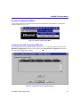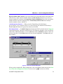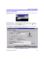
1
QuickSET Configuration Guide for CSX200, CSX400, CSX400-DC, CSX500, HSIM-W6, and HSIM-W84 9032691-03 Only qualified personnel should perform installation procedures. NOTICE Cabletron Systems reserves the right to make changes in specifications and other information contained in this document without prior notice. The reader should in all cases consult Cabletron Systems to determine whether any such changes have been made. The hardware, firmware, or software described in this manual is subject to change without notice. IN NO EVENT SHALL CABLETRON SYSTEMS BE LIABLE FOR ANY INCIDENTAL, INDIRECT, SPECIAL, OR CONSEQUENTIAL DAMAGES WHATSOEVER (INCLUDING BUT NOT LIMITED TO LOST PROFITS) ARISING OUT OF OR RELATED TO THIS MANUAL OR THE INFORMATION CONTAINED IN IT, EVEN IF CABLETRON SYSTEMS HAS BEEN ADVISED OF, KNOWN, OR SHOULD HAVE KNOWN, THE POSSIBILITY OF SUCH DAMAGES. 1999 by Cabletron Systems, Inc., P.O. Box 5005, Rochester, NH 03866-5005 All Rights Reserved Printed in the United States of America Order Number 9032691-03 April 1999 Cabletron Systems and QuickSET are registered trademarks and CyberSwitch is a trademark of Cabletron Systems, Inc. All other product names mentioned in this manual may be trademarks or registered trademarks of their respective companies. FCC NOTICE This device complies with Part 15 of the FCC rules. Operation is subject to the following two conditions: (1) this device may not cause harmful interference, and (2) this device must accept any interference received, including interference that may cause undesired operation. NOTE: This equipment has been tested and found to comply with the limits for a Class A digital device, pursuant to Part 15 of the FCC rules. These limits are designed to provide reasonable protection against harmful interference when the equipment is operated in a commercial environment. This equipment uses, generates, and can radiate radio frequency energy and if not installed in accordance with the operator’s manual, may cause harmful interference to radio communications. Operation of this equipment in a residential area is likely to cause interference in which case the user will be required to correct the interference at his own expense. WARNING: Changes or modifications made to this device which are not expressly approved by the party responsible for compliance could void the user’s authority to operate the equipment. QuickSET Configuration Guide i Notice INDUSTRY CANADA NOTICE This digital apparatus does not exceed the Class A limits for radio noise emissions from digital apparatus set out in the Radio Interference Regulations of the Canadian Department of Communications. Le présent appareil numérique n’émet pas de bruits radioélectriques dépassant les limites applicables aux appareils numériques de la class A prescrites dans le Règlement sur le brouillage radioélectrique édicté par le ministère des Communications du Canada. NOTICE: The Industry Canada label identifies certified equipment. This certification means that the equipment meets telecommunications network protective, operational and safety requirements as prescribed in the appropriate Terminal Equipment Technical Requirements documents (s). The department does not guarantee the equipment will operate to the user’s satisfaction. Before installing this equipment, users should ensure that it is permissible to be connected to the facilities of the local telecommunications company. The equipment must also be installed using an acceptable method of connection. The customer should be aware that compliance with the above conditions may not prevent degradation of service in some situations. Repairs to certified equipment should be coordinated by a representative designated by the supplier. Any repairs or alterations made by the user to this equipment, or equipment malfunctions, may give the telecommunications company cause to request the user to disconnect the equipment. Users should ensure for their own protection that the electrical ground connections of the power utility, telephone lines and internal metallic water pipe system, if present, are connected together. This precaution may be particularly important in rural areas. Caution: Users should not attempt to make such connections themselves, but should contact the appropriate electric inspection authority, or electrician, as appropriate. NOTICE: The Ringer Equivalence Number (REN) assigned to each terminal device provides an indication of the maximum number of terminals allowed to be connected to a telephone interface. The termination on an interface may consist of any combination of devices subject only to the requirement that the sum of the ringer equivalence Numbers of all the devices does not exceed 5. VCCI NOTICE This is a Class A product based on the standard of the Voluntary Control Council for Interference by Information Technology Equipment (VCCI). If this equipment is used in a domestic environment, radio disturbance may arise. When such trouble occurs, the user may be required to take corrective actions. ii QuickSET Configuration Guide Notice CABLETRON SYSTEMS, INC. PROGRAM LICENSE AGREEMENT IMPORTANT: THIS LICENSE APPLIES FOR USE OF PRODUCT IN THE FOLLOWING GEOGRAPHICAL REGIONS: CANADA MEXICO CENTRAL AMERICA SOUTH AMERICA BEFORE OPENING OR UTILIZING THE ENCLOSED PRODUCT, CAREFULLY READ THIS LICENSE AGREEMENT. This document is an agreement (“Agreement”) between You, the end user, and Cabletron Systems, Inc. (“Cabletron”) that sets forth your rights and obligations with respect to the Cabletron software program (“Program”) in the package. The Program may be contained in firmware, chips or other media. UTILIZING THE ENCLOSED PRODUCT, YOU ARE AGREEING TO BECOME BOUND BY THE TERMS OF THIS AGREEMENT, WHICH INCLUDES THE LICENSE AND THE LIMITATION OF WARRANTY AND DISCLAIMER OF LIABILITY. IF YOU DO NOT AGREE TO THE TERMS OF THIS AGREEMENT, RETURN THE UNOPENED PRODUCT TO CABLETRON OR YOUR DEALER, IF ANY, WITHIN TEN (10) DAYS FOLLOWING THE DATE OF RECEIPT FOR A FULL REFUND. IF YOU HAVE ANY QUESTIONS ABOUT THIS AGREEMENT, CONTACT CABLETRON SYSTEMS (603) 332-9400. Attn: Legal Department. 1. LICENSE. You have the right to use only the one (1) copy of the Program provided in this package subject to the terms and conditions of this License Agreement. You may not copy, reproduce or transmit any part of the Program except as permitted by the Copyright Act of the United States or as authorized in writing by Cabletron. 2. OTHER RESTRICTIONS. You may not reverse engineer, decompile, or disassemble the Program. 3. APPLICABLE LAW. This License Agreement shall be interpreted and governed under the laws and in the state and federal courts of New Hampshire. You accept the personal jurisdiction and venue of the New Hampshire courts. 4. EXPORT REQUIREMENTS. You understand that Cabletron and its Affiliates are subject to regulation by agencies of the U.S. Government, including the U.S. Department of Commerce, which prohibit export or diversion of certain technical products to certain countries, unless a license to export the product is obtained from the U.S. Government or an exception from obtaining such license may be relied upon by the exporting party. If the Program is exported from the United States pursuant to the License Exception CIV under the U.S. Export Administration Regulations, You agree that You are a civil end user of the Program and agree that You will use the Program for civil end uses only and not for military purposes. QuickSET Configuration Guide iii Notice If the Program is exported from the United States pursuant to the License Exception TSR under the U.S. Export Administration Regulations, in addition to the restriction on transfer set forth in Sections 1 or 2 of this Agreement, You agree not to (i) reexport or release the Program, the source code for the Program or technology to a national of a country in Country Groups D:1 or E:2 (Albania, Armenia, Azerbaijan, Belarus, Bulgaria, Cambodia, Cuba, Estonia, Georgia, Iraq, Kazakhstan, Kyrgyzstan, Laos, Latvia, Libya, Lithuania, Moldova, North Korea, the People’s Republic of China, Romania, Russia, Rwanda, Tajikistan, Turkmenistan, Ukraine, Uzbekistan, Vietnam, or such other countries as may be designated by the United States Government), (ii) export to Country Groups D:1 or E:2 (as defined herein) the direct product of the Program or the technology, if such foreign produced direct product is subject to national security controls as identified on the U.S. Commerce Control List, or (iii) if the direct product of the technology is a complete plant o r any major component of a plant, export to Country Groups D:1 or E:2 the direct product of the plant or a major component thereof, if such foreign produced direct product is subject to national security controls as identified on the U.S. Commerce Control List or is subject to State Department controls under the U.S. Munitions List. 5. UNITED STATES GOVERNMENT RESTRICTED RIGHTS. The enclosed Product (i) was developed solely at private expense; (ii) contains “restricted computer software” submitted with restricted rights in accordance with section 52.227-19 (a) through (d) of the Commercial Computer Software-Restricted Rights Clause and its successors, and (iii) in all respects is proprietary data belonging to Cabletron and/or its suppliers. For Department of Defense units, the Product is considered commercial computer software in accordance with DFARS section 227.7202-3 and its successors, and use, duplication, or disclosure by the Government is subject to restrictions set forth herein. 6. EXCLUSION OF WARRANTY. Except as may be specifically provided by Cabletron in writing, Cabletron makes no warranty, expressed or implied, concerning the Program (including its documentation and media). CABLETRON DISCLAIMS ALL WARRANTIES, OTHER THAN THOSE SUPPLIED TO YOU BY CABLETRON IN WRITING, EITHER EXPRESS OR IMPLIED, INCLUDING BUT NOT LIMITED TO IMPLIED WARRANTIES OF MERCHANTABILITY AND FITNESS FOR A PARTICULAR PURPOSE, WITH RESPECT TO THE PROGRAM, THE ACCOMPANYING WRITTEN MATERIALS, AND ANY ACCOMPANYING HARDWARE. 7. NO LIABILITY FOR CONSEQUENTIAL DAMAGES. IN NO EVENT SHALL CABLETRON OR ITS SUPPLIERS BE LIABLE FOR ANY DAMAGES WHATSOEVER (INCLUDING, WITHOUT LIMITATION, DAMAGES FOR LOSS OF BUSINESS, PROFITS, BUSINESS INTERRUPTION, LOSS OF BUSINESS INFORMATION, SPECIAL, INCIDENTAL, CONSEQUENTIAL, OR RELIANCE DAMAGES, OR OTHER LOSS) ARISING OUT OF THE USE OR INABILITY TO USE THIS CABLETRON PRODUCT, EVEN IF CABLETRON HAS BEEN ADVISED OF THE POSSIBILITY OF SUCH DAMAGES. BECAUSE SOME STATES DO NOT ALLOW THE EXCLUSION OR LIMITATION OF LIABILITY FOR CONSEQUENTIAL OR INCIDENTAL DAMAGES, OR IN THE DURATION OR LIMITATION OF IMPLIED WARRANTIES IN SOME INSTANCES, THE ABOVE LIMITATION AND EXCLUSIONS MAY NOT APPLY TO YOU. iv QuickSET Configuration Guide Notice CABLETRON SYSTEMS SALES AND SERVICE, INC. PROGRAM LICENSE AGREEMENT IMPORTANT: THIS LICENSE APPLIES FOR USE OF PRODUCT IN THE UNITED STATES OF AMERICA AND BY UNITED STATES OF AMERICA GOVERNMENT END USERS. BEFORE OPENING OR UTILIZING THE ENCLOSED PRODUCT, CAREFULLY READ THIS LICENSE AGREEMENT. This document is an agreement (“Agreement”) between You, the end user, and Cabletron Systems Sales and Service, Inc. (“Cabletron”) that sets forth your rights and obligations with respect to the Cabletron software program (“Program”) in the package. The Program may be contained in firmware, chips or other media. UTILIZING THE ENCLOSED PRODUCT, YOU ARE AGREEING TO BECOME BOUND BY THE TERMS OF THIS AGREEMENT, WHICH INCLUDES THE LICENSE AND THE LIMITATION OF WARRANTY AND DISCLAIMER OF LIABILITY. IF YOU DO NOT AGREE TO THE TERMS OF THIS AGREEMENT, RETURN THE UNOPENED PRODUCT TO CABLETRON OR YOUR DEALER, IF ANY, WITHIN TEN (10) DAYS FOLLOWING THE DATE OF RECEIPT FOR A FULL REFUND. IF YOU HAVE ANY QUESTIONS ABOUT THIS AGREEMENT, CONTACT CABLETRON SYSTEMS (603) 332-9400. Attn: Legal Department. 1. LICENSE. You have the right to use only the one (1) copy of the Program provided in this package subject to the terms and conditions of this License Agreement. You may not copy, reproduce or transmit any part of the Program except as permitted by the Copyright Act of the United States or as authorized in writing by Cabletron. 2. OTHER RESTRICTIONS. You may not reverse engineer, decompile, or disassemble the Program. 3. APPLICABLE LAW. This License Agreement shall be interpreted and governed under the laws and in the state and federal courts of New Hampshire. You accept the personal jurisdiction and venue of the New Hampshire courts. 4. EXPORT REQUIREMENTS. You understand that Cabletron and its Affiliates are subject to regulation by agencies of the U.S. Government, including the U.S. Department of Commerce, which prohibit export or diversion of certain technical products to certain countries, unless a license to export the product is obtained from the U.S. Government or an exception from obtaining such license may be relied upon by the exporting party. If the Program is exported from the United States pursuant to the License Exception CIV under the U.S. Export Administration Regulations, You agree that You are a civil end user of the Program and agree that You will use the Program for civil end uses only and not for military purposes. QuickSET Configuration Guide v Notice If the Program is exported from the United States pursuant to the License Exception TSR under the U.S. Export Administration Regulations, in addition to the restriction on transfer set forth in Sections 1 or 2 of this Agreement, You agree not to (i) reexport or release the Program, the source code for the Program or technology to a national of a country in Country Groups D:1 or E:2 (Albania, Armenia, Azerbaijan, Belarus, Bulgaria, Cambodia, Cuba, Estonia, Georgia, Iraq, Kazakhstan, Kyrgyzstan, Laos, Latvia, Libya, Lithuania, Moldova, North Korea, the People’s Republic of China, Romania, Russia, Rwanda, Tajikistan, Turkmenistan, Ukraine, Uzbekistan, Vietnam, or such other countries as may be designated by the United States Government), (ii) export to Country Groups D:1 or E:2 (as defined herein) the direct product of the Program or the technology, if such foreign produced direct product is subject to national security controls as identified on the U.S. Commerce Control List, or (iii) if the direct product of the technology is a complete plant o r any major component of a plant, export to Country Groups D:1 or E:2 the direct product of the plant or a major component thereof, if such foreign produced direct product is subject to national security controls as identified on the U.S. Commerce Control List or is subject to State Department controls under the U.S. Munitions List. 5. UNITED STATES GOVERNMENT RESTRICTED RIGHTS. The enclosed Product (i) was developed solely at private expense; (ii) contains “restricted computer software” submitted with restricted rights in accordance with section 52.227-19 (a) through (d) of the Commercial Computer Software-Restricted Rights Clause and its successors, and (iii) in all respects is proprietary data belonging to Cabletron and/or its suppliers. For Department of Defense units, the Product is considered commercial computer software in accordance with DFARS section 227.7202-3 and its successors, and use, duplication, or disclosure by the Government is subject to restrictions set forth herein. 6. EXCLUSION OF WARRANTY. Except as may be specifically provided by Cabletron in writing, Cabletron makes no warranty, expressed or implied, concerning the Program (including its documentation and media). CABLETRON DISCLAIMS ALL WARRANTIES, OTHER THAN THOSE SUPPLIED TO YOU BY CABLETRON IN WRITING, EITHER EXPRESS OR IMPLIED, INCLUDING BUT NOT LIMITED TO IMPLIED WARRANTIES OF MERCHANTABILITY AND FITNESS FOR A PARTICULAR PURPOSE, WITH RESPECT TO THE PROGRAM, THE ACCOMPANYING WRITTEN MATERIALS, AND ANY ACCOMPANYING HARDWARE. 7. NO LIABILITY FOR CONSEQUENTIAL DAMAGES. IN NO EVENT SHALL CABLETRON OR ITS SUPPLIERS BE LIABLE FOR ANY DAMAGES WHATSOEVER (INCLUDING, WITHOUT LIMITATION, DAMAGES FOR LOSS OF BUSINESS, PROFITS, BUSINESS INTERRUPTION, LOSS OF BUSINESS INFORMATION, SPECIAL, INCIDENTAL, CONSEQUENTIAL, OR RELIANCE DAMAGES, OR OTHER LOSS) ARISING OUT OF THE USE OR INABILITY TO USE THIS CABLETRON PRODUCT, EVEN IF CABLETRON HAS BEEN ADVISED OF THE POSSIBILITY OF SUCH DAMAGES. BECAUSE SOME STATES DO NOT ALLOW THE EXCLUSION OR LIMITATION OF LIABILITY FOR CONSEQUENTIAL OR INCIDENTAL DAMAGES, OR IN THE DURATION OR LIMITATION OF IMPLIED WARRANTIES IN SOME INSTANCES, THE ABOVE LIMITATION AND EXCLUSIONS MAY NOT APPLY TO YOU. vi QuickSET Configuration Guide Notice CABLETRON SYSTEMS LIMITED PROGRAM LICENSE AGREEMENT IMPORTANT: THIS LICENSE APPLIES FOR THE USE OF THE PRODUCT IN THE FOLLOWING GEOGRAPHICAL REGIONS: EUROPE MIDDLE EAST AFRICA ASIA AUSTRALIA PACIFIC RIM BEFORE OPENING OR UTILIZING THE ENCLOSED PRODUCT, CAREFULLY READ THIS LICENSE AGREEMENT. This document is an agreement (“Agreement”) between You, the end user, and Cabletron Systems Limited (“Cabletron”) that sets forth your rights and obligations with respect to the Cabletron software program (“Program”) in the package. The Program may be contained in firmware, chips or other media. UTILIZING THE ENCLOSED PRODUCT, YOU ARE AGREEING TO BECOME BOUND BY THE TERMS OF THIS AGREEMENT, WHICH INCLUDES THE LICENSE AND THE LIMITATION OF WARRANTY AND DISCLAIMER OF LIABILITY. IF YOU DO NOT AGREE TO THE TERMS OF THIS AGREEMENT, RETURN THE UNOPENED PRODUCT TO CABLETRON OR YOUR DEALER, IF ANY, WITHIN TEN (10) DAYS FOLLOWING THE DATE OF RECEIPT FOR A FULL REFUND. IF YOU HAVE ANY QUESTIONS ABOUT THIS AGREEMENT, CONTACT CABLETRON SYSTEMS (603) 332-9400. Attn: Legal Department. 1. LICENSE. You have the right to use only the one (1) copy of the Program provided in this package subject to the terms and conditions of this License Agreement. You may not copy, reproduce or transmit any part of the Program except as permitted by the Copyright Act of the United States or as authorized in writing by Cabletron. 2. OTHER RESTRICTIONS. You may not reverse engineer, decompile, or disassemble the Program. 3. APPLICABLE LAW. This License Agreement shall be governed in accordance with English law. The English courts shall have exclusive jurisdiction in the event of any disputes. 4. EXPORT REQUIREMENTS. You understand that Cabletron and its Affiliates are subject to regulation by agencies of the U.S. Government, including the U.S. Department of Commerce, which prohibit export or diversion of certain technical products to certain countries, unless a license to export the product is obtained from the U.S. Government or an exception from obtaining such license may be relied upon by the exporting party. If the Program is exported from the United States pursuant to the License Exception CIV under the U.S. Export Administration Regulations, You agree that You are a civil end user of the Program and agree that You will use the Program for civil end uses only and not for military purposes. QuickSET Configuration Guide vii Notice If the Program is exported from the United States pursuant to the License Exception TSR under the U.S. Export Administration Regulations, in addition to the restriction on transfer set forth in Sections 1 or 2 of this Agreement, You agree not to (i) reexport or release the Program, the source code for the Program or technology to a national of a country in Country Groups D:1 or E:2 (Albania, Armenia, Azerbaijan, Belarus, Bulgaria, Cambodia, Cuba, Estonia, Georgia, Iraq, Kazakhstan, Kyrgyzstan, Laos, Latvia, Libya, Lithuania, Moldova, North Korea, the People’s Republic of China, Romania, Russia, Rwanda, Tajikistan, Turkmenistan, Ukraine, Uzbekistan, Vietnam, or such other countries as may be designated by the United States Government), (ii) export to Country Groups D:1 or E:2 (as defined herein) the direct product of the Program or the technology, if such foreign produced direct product is subject to national security controls as identified on the U.S. Commerce Control List, or (iii) if the direct product of the technology is a complete plant o r any major component of a plant, export to Country Groups D:1 or E:2 the direct product of the plant or a major component thereof, if such foreign produced direct product is subject to national security controls as identified on the U.S. Commerce Control List or is subject to State Department controls under the U.S. Munitions List. 5. UNITED STATES GOVERNMENT RESTRICTED RIGHTS. The enclosed Product (i) was developed solely at private expense; (ii) contains “restricted computer software” submitted with restricted rights in accordance with section 52.227-19 (a) through (d) of the Commercial Computer Software-Restricted Rights Clause and its successors, and (iii) in all respects is proprietary data belonging to Cabletron and/or its suppliers. For Department of Defense units, the Product is considered commercial computer software in accordance with DFARS section 227.7202-3 and its successors, and use, duplication, or disclosure by the Government is subject to restrictions set forth herein. 6. EXCLUSION OF WARRANTY. Except as may be specifically provided by Cabletron in writing, Cabletron makes no warranty, expressed or implied, concerning the Program (including its documentation and media). CABLETRON DISCLAIMS ALL WARRANTIES, OTHER THAN THOSE SUPPLIED TO YOU BY CABLETRON IN WRITING, EITHER EXPRESS OR IMPLIED, INCLUDING BUT NOT LIMITED TO IMPLIED WARRANTIES OF MERCHANTABILITY AND FITNESS FOR A PARTICULAR PURPOSE, WITH RESPECT TO THE PROGRAM, THE ACCOMPANYING WRITTEN MATERIALS, AND ANY ACCOMPANYING HARDWARE. 7. NO LIABILITY FOR CONSEQUENTIAL DAMAGES. IN NO EVENT SHALL CABLETRON OR ITS SUPPLIERS BE LIABLE FOR ANY DAMAGES WHATSOEVER (INCLUDING, WITHOUT LIMITATION, DAMAGES FOR LOSS OF BUSINESS, PROFITS, BUSINESS INTERRUPTION, LOSS OF BUSINESS INFORMATION, SPECIAL, INCIDENTAL, CONSEQUENTIAL, OR RELIANCE DAMAGES, OR OTHER LOSS) ARISING OUT OF THE USE OR INABILITY TO USE THIS CABLETRON PRODUCT, EVEN IF CABLETRON HAS BEEN ADVISED OF THE POSSIBILITY OF SUCH DAMAGES. BECAUSE SOME STATES DO NOT ALLOW THE EXCLUSION OR LIMITATION OF LIABILITY FOR CONSEQUENTIAL OR INCIDENTAL DAMAGES, OR IN THE DURATION OR LIMITATION OF IMPLIED WARRANTIES IN SOME INSTANCES, THE ABOVE LIMITATION AND EXCLUSIONS MAY NOT APPLY TO YOU. viii QuickSET Configuration Guide Notice SAFETY INFORMATION CLASS 1 LASER TRANSCEIVERS THE FE-100F3 FAST ETHERNET INTERFACE MODULE, FPIM-05 AND FPIM-07 FDDI PORT INTERFACE MODULES, AND APIM-29 ATM PORT INTERFACE MODULE USE CLASS 1 LASER TRANSCEIVERS. READ THE FOLLOWING SAFETY INFORMATION BEFORE INSTALLING OR OPERATING THESE MODULES. The Class 1 laser transceivers use an optical feedback loop to maintain Class 1 operation limits. This control loop eliminates the need for maintenance checks or adjustments. The output is factory set, and does not allow any user adjustment. Class 1 Laser transceivers comply with the following safety standards: • 21 CFR 1040.10 and 1040.11 U.S. Department of Health and Human Services (FDA). • IEC Publication 825 (International Electrotechnical Commission). • CENELEC EN 60825 (European Committee for Electrotechnical Standardization). When operating within their performance limitations, laser transceiver output meets the Class 1 accessible emission limit of all three standards. Class 1 levels of laser radiation are not considered hazardous. SAFETY INFORMATION CLASS 1 LASER TRANSCEIVERS LASER RADIATION AND CONNECTORS When the connector is in place, all laser radiation remains within the fiber. The maximum amount of radiant power exiting the fiber (under normal conditions) is -12.6 dBm or 55 x 10-6 watts. Removing the optical connector from the transceiver allows laser radiation to emit directly from the optical port. The maximum radiance from the optical port (under worst case conditions) is 0.8 W cm-2 or 8 x 10³ W m2 sr-1. Do not use optical instruments to view the laser output. The use of optical instruments to view laser output increases eye hazard. When viewing the output optical port, power must be removed from the network adapter. QuickSET Configuration Guide ix Notice DECLARATION OF CONFORMITY Application of Council Directive(s): Manufacturer’s Name: Manufacturer’s Address: European Representative Name: European Representative Address: Conformance to Directive(s)/Product Standards: Equipment Type/Environment: 89/336/EEC 73/23/EEC Cabletron Systems, Inc. 35 Industrial Way PO Box 5005 Rochester, NH 03867 Mr. J. Solari Cabletron Systems Limited Nexus House, Newbury Business Park London Road, Newbury Berkshire RG13 2PZ, England EC Directive 89/336/EEC EC Directive 73/23/EEC EN 55022 EN 50082-1 EN 60950 Networking Equipment, for use in a Commercial or Light Industrial Environment. We the undersigned, hereby declare, under our sole responsibility, that the equipment packaged with this notice conforms to the above directives. Manufacturer Legal Representative in Europe Mr. Ronald Fotino ___________________________________ Full Name Mr. J. Solari ___________________________________ Full Name Compliance Engineering Manager ___________________________________ Title Managing Director - E.M.E.A. ___________________________________ Title Rochester, NH, USA ___________________________________ Location Newbury, Berkshire, England ___________________________________ Location x QuickSET Configuration Guide Contents CONFIGURATION WITH QuickSET Ethernet Configuration .............................................................................................. 3 Ethernet 1 and 2 Configuration Window ........................................................... 3 Local HSIM IP Address Window......................................................................... 5 System Passwords.............................................................................................. 7 Wide Area Module Configuration ............................................................................. 9 Wide Area T1 Configuration Window ................................................................ 9 Wide Area E1 Configuration Window .............................................................. 11 Wide Area DI Configuration Window ............................................................... 12 DI Functionality ........................................................................................... 13 Wide Area Synchronous Configuration Window............................................ 16 Wide Area DDS Configuration Window ........................................................... 18 Wide Area HDSL Configuration Window......................................................... 19 Wide Area Time Slot Configuration Windows ....................................................... 20 Wide Area Frame Relay Time Slot Configuration Window ............................ 20 Wide Area PPP Time Slot Configuration Window .......................................... 21 Wide Area HDSL Time Slot Configuration Window........................................ 24 General Configuration....................................................................................... 26 DHCP Settings Configuration Window ..................................................... 26 Priority IP Queuing ..................................................................................... 29 Bridging and Routing Configuration...................................................................... 31 Bridging and Routing Configuration Window ................................................ 31 Firewall Configuration Window ................................................................. 34 Bridging and Routing (WAN Frame Type) Configuration Window ............... 38 Routing Configuration Window........................................................................ 40 IP Routing Configuration .................................................................................. 40 IPX Routing Configuration................................................................................ 42 IPX Host Map Window ................................................................................ 42 QuickSET Configuration Guide xi Contents Advanced Routing Configuration Window ..................................................... 45 Advanced IP Routing Settings................................................................... 46 Advanced IP Routing Options ................................................................... 46 NAT Settings Configuration Window ........................................................ 47 IP Host Map Window................................................................................... 49 Modify IP Host Window .............................................................................. 51 OSPF Redistribute Routes................................................................................ 55 QuickSET Pull-Down Menus ................................................................................... 57 File Menu ............................................................................................................ 57 Firmware Upgrade Menu................................................................................... 59 Runtime Configuration Menu ........................................................................... 61 Compression and Congestion Window........................................................... 61 Set Device Time and Date................................................................................. 63 QuickSET Configuration (Firmware Version 02.XX.XX) ....................................... 64 Ethernet Port Configuration.................................................................................... 66 Ethernet 1 and 2 Configuration Window ......................................................... 66 Wide Area - 1 and 2 Configuration Windows......................................................... 70 Wide Area T1 - Configuration Window ............................................................ 71 Wide Area E1 - Configuration Window ............................................................ 74 Wide Area DI - Configuration Window............................................................. 76 DI Functionality ........................................................................................... 76 Configuration Information ................................................................................ 78 DLCI Setup Button............................................................................................. 79 Wide Area Synchronous - Configuration Window ......................................... 80 Wide Area DDS - Configuration Window......................................................... 83 Wide Area HDSL - Configuration Window....................................................... 85 Wide Area ISDN - Configuration Window........................................................ 87 ISDN Configuration Parameters ................................................................ 88 ISDN Profile Wizard..................................................................................... 88 Modify Profile Button.................................................................................. 91 Wide Area Time Slot Configuration Windows ....................................................... 95 Wide Area Frame Relay Time Slot Configuration Window ............................ 95 Wide Area PPP Time Slot Configuration Window .......................................... 97 xii QuickSET Configuration Guide Contents Wide Area HDSL Time Slot Configuration Window........................................ 99 Wide Area HDLC Time Slot Configuration Window ..................................... 100 Line Coding...................................................................................................... 101 General Configuration ........................................................................................... 102 DHCP Settings Configuration Window ................................................... 102 Priority IP Queuing .......................................................................................... 104 Interfaces Window........................................................................................... 106 Alias Setup Button .......................................................................................... 106 Interface Backup Setup Button ...................................................................... 107 Dial-Up Settings Button .................................................................................. 109 Spoofing Settings Button ............................................................................... 110 Bridging and Routing - Configuration.................................................................. 111 Bridging and Routing Window ....................................................................... 111 Firewall Window ........................................................................................ 114 Second Bridging and Routing Window................................................................ 119 Routing Configuration Window ............................................................................ 121 IP Routing Configuration ................................................................................ 121 Advanced Options Window ............................................................................ 122 Split Horizons Window ............................................................................. 123 Advanced IP Routing Options........................................................................ 124 Redirector Window ................................................................................... 124 NAT Settings Window............................................................................... 124 Routing Information Protocol Options.................................................... 127 RIP-1 vs. RIP-2........................................................................................... 127 Subnet Masks ............................................................................................ 127 Next Hop .................................................................................................... 128 Metrics........................................................................................................ 128 Split Horizon .............................................................................................. 128 Authentication ........................................................................................... 129 Multicasting ............................................................................................... 129 Compatibility Switch................................................................................. 129 The Receive Control ................................................................................. 129 OSPF Settings ........................................................................................... 130 QuickSET Configuration Guide xiii Contents OSPF Redistribute Routes.............................................................................. 134 IP Host Map Window................................................................................. 136 Modify IP Host Window ............................................................................ 137 IPX Routing Configuration Window............................................................... 138 IPX Host Map Window .............................................................................. 138 QuickSET - Pull-Down Menus ............................................................................... 141 File Menu .......................................................................................................... 141 Create Configuration Text File ....................................................................... 142 Firmware Upgrade Menu................................................................................. 143 Runtime Configuration Menu ......................................................................... 144 Compression and Congestion Window......................................................... 144 Set Device Time and Date............................................................................... 147 xiv QuickSET Configuration Guide Configuration with QuickSET NOTE This manual is divided into two parts. The first part is the QuickSET configuration procedure for Version 1.xx.xx Firmware. The second part is the QuickSET configuration procedure for Version 2.xx.xx Firmware section QuickSET Configuration (Firmware Version 02.XX.XX). This manual contains QuickSET configuration procedures for the HSIM-W6, HSIM-W84, and CSX200, CSX400, and CSX500 CyberSWITCHes. The manual covers two versions of firmware. The QuickSET software will automatically determine which version of firmware is in use in your device, and select the appropriate configuration windows for your configuration procedure. The firmware version number appears on the first QuickSET screen in the area that is highlighted in Figure 1 below. If your QuickSET screen shows firmware versions 02.XX.XX or greater, your QuickSET configuration instructions begin at QuickSET Configuration (Firmware Version 02.XX.XX). Otherwise use the QuickSET configuration instructions that begin here. Firmware Version Number Figure 1 First QuickSET Screen Showing Firmware Version Number QuickSET Configuration Guide 1 Configuration with QuickSET If your system is connected to more than one network, you will see the Local User Networks window shown below in Figure 2. Use the scroll button to select the network connection that your QuickSET-configurable device is attached to. Click OK to select the network that your device is on. Figure 2 Local User Networks Window Normally, QuickSET automatically establishes a communication link with the device that you wish to configure. However, under certain circumstances, QuickSET may not be able to locate the device automatically. In this case, the IP Address window shown in Figure 3 displays. Figure 3 IP Address Window 2 QuickSET Configuration Guide Ethernet Configuration Enter the IP address of the QuickSET-configurable device in the appropriate field and the password if applicable (the default password is public). Click on the Create a Route... checkbox to create a route to this device on your PC. Click on the OK button and QuickSET locates the device on the network and displays the First Introductory window. Click on the Next>> button and go to the Ethernet 1 and 2 Configuration window (shown on the following page) in Figure 4, (or for HSIM-W6 and HSIM W-84, the Local HSIM IP Address Window, shown in Figure 5) to continue the configuration. Ethernet Configuration This section explains how to configure the Ethernet 1 and 2 fields using QuickSET. Note: there will be only one local Ethernet configuration window for the CSX200 and CSX500 devices. Ethernet 1 and 2 Configuration Window The Ethernet 1 and 2 configuration window, shown in Figure 4 on the following page, displays after clicking on the Next>> button in the Introductory window. The Local Ethernet IP address and Subnet Mask fields shown on the Ethernet 1 and 2 configuration window are used for setting an IP address and Subnet Mask. This section describes each of the fields on the Ethernet 1 and 2 configuration window. QuickSET Configuration Guide 3 Configuration with QuickSET Figure 4 Ethernet 1 and 2 Configuration Window Local Ethernet (1 and 2) IP Address — Displays the IP Address for the Local Ethernet interface selected (Ethernet 1 or Ethernet 2). Place the cursor in this field and type the preferred IP Address in Dotted Decimal Notation (DDN) format. The Local Ethernet 1 IP Address must be entered in order to continue configuration. Local Ethernet (1 and 2) Subnet Mask — The Subnet Mask takes the same form as an IP address; four groups of three decimal digits, separated by periods. Each group must be in the numerical range of 0 to 255. When you click on the Subnet Mask field (the first time you use QuickSET), a default Subnet Mask displays, based on the IP address you entered. If you wish to use a different Subnet Mask, enter it at this time in DDN format. The Local Ethernet 1 Subnet Mask must be entered in this field to continue. 4 QuickSET Configuration Guide Ethernet Configuration Local HSIM IP Address Window If you are configuring an HSIM-W6 or -W84, you will see the Local HSIM IP Address Window shown below in Figure 5 in place of the Ethernet 1 and 2 Configuration Window. Figure 5 Local HSIM IP Address Window Local HSIM IP Address Field — Displays the IP Address for the Local HSIM Ethernet interface. Place the cursor in this field and type the preferred IP Address in Dotted Decimal Notation (DDN) format. Local HSIM Subnet Mask Field — The Subnet Mask takes the same form as an IP address; four groups of three decimal digits, separated by periods. Each group must be in the numerical range of 0 to 255. If you wish to use a different Subnet Mask, enter it at this time in DDN format. QuickSET Configuration Guide 5 Configuration with QuickSET Secondary IPs — The Secondary IPs window and Modify Secondary IP windows shown in Figure 6 below. The Secondary IPs window displays after clicking on the Secondary IPs... button on the Ethernet 1 and 2 Configuration Window, and shows the list of current Secondary IP addresses. Figure 6 Secondary IPs and Modify Secondary Ip Windows HSIMs and CyberSWITCHes can support multiple IP Subnets, therefore, there can be multiple Secondary IP Addresses assigned to an Ethernet interface. To add a Secondary IP address, click on the Add button and enter the IP Address, and Subnet Mask in their corresponding fields. Note: only the CSX400 will have the Ethernet Interface # selection radio buttons. If you wish to modify an existing entry, click the Modify button and the Modify Secondary IP window, shown in Figure 6, appears. When you have modified the Secondary IP entry, click OK. Click the Done button when you have finished making changes. 6 QuickSET Configuration Guide Ethernet Configuration System Passwords The System Passwords window shown in Figure 7 on the following page, displays after clicking on the Passwords button in the Ethernet 1 and 2 configuration window, or the HSIM Local IP Address window. The system passwords used by QuickSET are the same as the Community Names of the device that are used in Local Management through a TELNET application. System passwords allow you to control management access by establishing three passwords. Each password controls a different level of access. Once passwords are assigned, you must use the SuperUser System password at the User Password prompt when initiating a QuickSET session. If you are configuring the device for the first time or if no passwords are assigned, the default System password for each access level is preset to public. The following definitions explain the fields in the System Passwords window. Read Only Access — This access level allows reading of device parameters not including system passwords. Place the cursor in this field and type the new system password. Retype the system password in the Confirm Password field below the Read Only Access field. Read/Write Access — This access level allows editing of some device configuration parameters not including changing system passwords. Place the cursor in this field and type the new system password. Retype the system password in the Confirm Password field below the Read/Write Access field. QuickSET (SuperUser) — This access level allows full management privileges. Place the cursor in this field and type the new system password. Retype the system password in the Confirm Password field below the QuickSET (SuperUser) field. ! CAUTION If you edit the SuperUser system password, record it for safekeeping. If you lose this password, you cannot perform management functions without returning the device to its factory default configuration. This effectively erases any configuration work you may have done. QuickSET Configuration Guide 7 Configuration with QuickSET Figure 7 System Passwords Window When you have finished configuring the system passwords, click on the OK button in the System Passwords window to return to the Ethernet 1 and 2 configuration window, or the Local HSIM IP Address window. When you have completed Ethernet (or Local HSIM IP Address) configuration, click on the Next>> button and go to Wide Area Module Configuration. 8 QuickSET Configuration Guide Wide Area Module Configuration Wide Area Module Configuration NOTE When configuring WAN Interface Port Modules (WPIMs) with QuickSET, the Wide Area configuration window that displays corresponds to the specific model of WPIM that is installed in your CyberSWITCH. The HSIM-W84 and CSX500 always employ four WPIM-T1 WAN interfaces. Refer to the appropriate section listed below to configure your Wide Area 1 (or 2 if applicable) Port Interface Module: Wide Area T1 Configuration Window Wide Area E1 Configuration Window Wide Area DI Configuration Window Wide Area Synchronous Configuration Window Wide Area DDS Configuration Window Wide Area HDSL Configuration Window Wide Area T1 Configuration Window The Wide Area T1 configuration window is shown in Figure 8, below. Figure 8 Wide Area T1 Configuration Window QuickSET Configuration Guide 9 Configuration with QuickSET This section explains how to configure the Wide Area T1 interface using QuickSET. The line configuration information shown must be supplied by your service provider. Factory default settings are in bold. The following definitions explain the fields in the T1 WAN configuration window. T1 Frame Type — Displays the T1 frame type. The selections are ESF (Extended Superframe) and D4 (AT&T D4). The default setting for this field is ESF. T1 Line BuildOut — Displays the signal level for the physical T1 line. Set this to 0 dB unless the service provider recommends another setting. The default setting for this field is 0 dB. The following options are available for this setting: 0 dB, -7.5 dB, and -15 dB. T1 Line Coding — Displays the line coding for the physical T1 line. The selections for this field are B8ZS and AMI. The default setting for this field is B8ZS. T1 Loop-Back — Network Loopback is a testing procedure that segments the line and allows you to isolate faults. The selections for this field are No Loop and Line Loop. In Line Loop all 24 channels are looped back to the T1 line. The CyberSWITCH or HSIM must be in Loop-Timing mode to use this option. The default setting is No Loop. T1 Transmit Clock Source — Displays the T1 Transmit Clock Source. The choices for this field are Loop-Timing (Extracted Line Data) and Local-Timing (Internal Clock). The default setting for this field is Loop-Timing. Protocol — Displays the active protocol for the Wide Area interface. The Protocol panel lets you select either Frame Relay or Point-to-Point. Link Management Protocol — If you selected Frame Relay protocol, this field displays Q.933 Annex A, or T1.617 Annex D. The default is T1.617 Annex D. This field is grayed out and not used for PPP. When you have completed Wide Area T1 configuration, click on Next>>, and go to the Wide Area Frame Relay Time Slot Configuration Window or Wide Area PPP Time Slot Configuration Window section, depending on which protocol you are using. 10 QuickSET Configuration Guide Wide Area Module Configuration Wide Area E1 Configuration Window The Wide Area (E1) configuration window is shown in Figure 9 below. The following section explains how to configure the E1 WAN interface using QuickSET. The line configuration information below, and on the following page must be supplied by your service provider. Factory default settings are in bold type. Figure 9 Wide Area E1 Configuration Window The following definitions explain the fields in the Wide Area E1 configuration window. E1 Frame Type — Displays the E1 frame type. The selection toggles between E1 and E1-CRC. The default setting for this field is E1. E1 Line Coding — Displays the line coding for the physical E1 line. The selections toggle between HDB3 and AMI. The default setting for this field is HDB3. E1 Loop-Back — Network Loopback is a testing procedure that segments the line and allows you to isolate faults. Click on the radio button to select either the No Loop or Line Loop option. In Line Loop, all 32 channels are looped back to the E1 line. The CyberSWITCH or HSIM must be in Loop-Timing mode to use this option. The default setting is No Loop. E1 Transmit Clock Source — Displays the E1 Transmit Clock Source. Click on the radio button to select either the Loop-Timing (Extracted Line Data) or Local-Timing (Internal Clock) option. The default setting for this field is Loop-Timing. Protocol — Displays the active protocol for the Wide Area interface. The Protocol panel lets you select either Frame Relay or Point-to-Point. QuickSET Configuration Guide 11 Configuration with QuickSET Link Management Protocol — If you selected Frame Relay protocol, this field displays Q.933 Annex A, or T1.617 Annex D. The default is T1.617 Annex D. This field is grayed out and not used for PPP. When you have completed configuration, click on the Next>> button and go to the Wide Area Frame Relay Time Slot Configuration Window or Wide Area PPP Time Slot Configuration Window section, depending on which protocol you are using. Wide Area DI Configuration Window The Wide Area (DI) configuration window is shown in Figure 10 below. The following section explains how to configure the Wide Area DI interface using QuickSET. Figure 10 Wide Area DI Configuration Window The line configuration information given below and on the following pages must be supplied by your service provider. The factory default settings are in bold. The WPIM-DI has two connectors allowing two devices to share the available Time Slots in a T1 WAN link; an NI (Network Interface) Port, and a DI (Drop and Insert) Port. 12 QuickSET Configuration Guide Wide Area Module Configuration DI Functionality Enable — The NI Port is connected to the T1 WAN connection. Any timeslot set to zero will pass (that timeslot) from the NI Port to the DI Port (see Figure 11 below). The clock must either be local or come into the WPIM-DI through the NI Port. Data From DI — The DI Port is connected to the T1 WAN connection. Any timeslot set to zero will pass (that timeslot) from the DI Port to the NI Port. The clock must come into the WPIM-DI through the NI Port. Disable — The Drop and Insert functionality is turned off. The NI Port is connected to the T1 WAN interface and no timeslots are passed to the DI Port regardless of whether they are set to zero or not. Site #1 WPIM-DI Voice/Data WPIM-DI Voice/Data DI NI Voice Voice PBX Clock: Loop Site #2 NI DI PBX Telco Cloud Clock: Loop Clock: Loop Clock: Local Clock: Loop Figure 11 DI Telco Timing Telco Timing — The following configuration, shown above in Figure 11, is a typical setup. The system clock source is supplied by the Telco cloud between the two sites. The DI functionality option is set to Enable for both WPIM-DIs. Transmit Clock Source must be set to Loop Timing at both sites for this configuration. Tail Circuit Timing — The configuration shown on the following page in Figure 12 describes “Tail Circuit Timing”. QuickSET Configuration Guide 13 Configuration with QuickSET WPIM-DI Site #1 Voice/Data WPIM-DI NI DI Site #2 NI DI Voice/Data Voice Voice PBX PBX Telco Cloud Clock: Local Clock: Loop Clock: Loop Clock: Loop Clock: Loop Figure 12 DI Tail Circuit Timing The Tail Circuit (Figure 12, above) has the PBX as its timing source in site #1. The DI functionality for Site #1 is set to Data From DI. The DI functionality for Site #2 is set to Enable. The Transmit Clock Source must be set to Loop Timing at both sites for this configuration. Site #1 Voice WPIM-DI Voice/Data DI NI NI DI Voice Telco Cloud PBX Clock: Loop Voice/Data WPIM-DI Site #2 PBX Clock: Loop Clock: Local Clock: Loop Clock: Loop Figure 13 DI Internal Timing Internal Timing — For the Internal Timing configuration shown in Figure 13, above, the clock source is the WPIM-DI at Site # 1. DI functionality is set to Enable for both sites. Transmit Clock Source must be set to Local Timing for site #1, and to Loop Timing for site #2. T1 Frame Type — Displays the frame type. Click on the radio button to select either the ESF or D4 option. The default setting for this field is ESF. 14 QuickSET Configuration Guide Wide Area Module Configuration T1 Line BuildOut — Displays the signal level for the physical line. Set this to 0 dB unless the service provider recommends another setting. The default setting for this field is 0 dB. Click on the appropriate radio button for the following levels: 0 (Zero) dB, -7.5 dB, and -15 dB. T1 Line Coding — Displays the line coding for the physical line. The selections toggle between B8ZS and AMI. The default setting for this field is B8ZS. T1 Loop-Back — Network Loopback is a testing procedure that segments the line and allows you to isolate faults. The selections for this field toggle between No Loop and Line Loop. In Line Loop all 24 channels are looped back to the line. The CyberSWITCH or HSIM must be in Loop-Timing mode to use this option. The default setting is No Loop. T1 Transmit Clock Source — Displays the Transmit Clock Source. Click on the radio button to select either the Loop-Timing (Extracted Line Data) or Local-Timing (Internal Clock) option. The default setting for this field is Loop-Timing. Protocol — Displays the active protocol for the Wide Area interface. The Protocol panel lets you select either Frame Relay or Point-to-Point. Link Management Protocol — If you selected Frame Relay protocol, this field displays Q.933 Annex A, or T1.617 Annex D. The default is T1.617 Annex D. This field is grayed out and not used for PPP. When you have completed Wide Area configuration, click on the Next>> button, and go to the Wide Area Frame Relay Time Slot Configuration Window or the Wide Area PPP Time Slot Configuration Window section. QuickSET Configuration Guide 15 Configuration with QuickSET Wide Area Synchronous Configuration Window The Wide Area Synchronous configuration window is shown in Figure 14 below. Figure 14 Wide Area Synchronous Configuration Window This section explains how to configure the Synchronous WAN port using QuickSET. The line configuration information shown on the following page is determined by your service provider. Factory default settings are in bold. The following definitions explain the fields in the Synchronous WAN configuration window. Sync Port Type — Displays the Synchronous port electrical interface type. The selections for this field are V.35, RS422, RS232, and X.21. The default setting for this field is V.35. Table 1 explains the options for the Sync Port Type. Table 1 16 Sync Port Types Sync Port Type Interface Type Cable Type Cabletron Part Number RS422 RS449 RS449 9380120 RS232 RS232 RS232 9380122 V.35 V.35 V.35 9380121 X.21 X.21 X.21 9380123 QuickSET Configuration Guide Wide Area Module Configuration Table 1 Sync Port Types Sync Port Type Interface Type Cable Type Cabletron Part Number RS422 RS530 RS530 9380124 RS422 RS530A RS530A 9380126 RS422 RS530 Alt A RS530 Alt A 9380125 RS422 RS530A Alt A RS530A Alt A 9380127 Sync Clock Speed — Displays your configured receive clock speed. The default setting for this field is 64000 bits per second. The information necessary for you to set this field is normally determined by the service provider. Select the down arrow button to make your selection from the list of clock speeds using the information provided by your service provider (if it is not listed, type the value in). Sync Flow Control — Displays the source of the Clear To Send (CTS) and the Force Data Set Ready (DSR) signals. The CTS signal is an input to the CyberSWITCH or HSIM. The CyberSWITCH or HSIM can either use or ignore the CTS signal. Clicking on the box indicates that the CyberSWITCH or HSIM ignores the CTS signal from an external DCE (Data Communications Equipment) and forces the signal high. The off setting indicates that the CTS signal is received from an external DCE. The default setting is off. The DSR signal is an input to the CyberSWITCH or HSIM. Clicking on the box indicates that DSR signal is internally forced high. The off setting indicates that the DSR signal is received from an external DCE. The default setting is off. Protocol — Displays the active protocol for the Wide Area interface. The Protocol panel lets you select either Frame Relay or Point-to-Point. Link Management Protocol — If you selected Frame Relay protocol, this field displays Q.933 Annex A, or T1.617 Annex D. The default is T1.617 Annex D. This field is grayed out and not used for PPP. When you have completed Wide Area Synchronous configuration, click on the Next>> button, and go to the General Configuration section of this procedure. QuickSET Configuration Guide 17 Configuration with QuickSET Wide Area DDS Configuration Window The Wide Area DDS configuration window is shown in Figure 15, below. The following section explains how to configure the Wide Area DDS interface using QuickSET. Figure 15 Wide Area DDS Configuration Window Table 2 shows the line configuration information determined by your service provider. The factory default settings are in bold. Table 2 Telco Configuration Information Configuration Information Required by User Configuration Information Supplied by Service Provider DDS Line Mode DDS-PRI or DDS-CC DDS Clock Source Loop-Timing or Local-Timing DDS Loop Back No Loop or Line Loop This section describes the fields in the Wide Area DDS configuration window. DDS Line Mode — Displays the DDS Line Mode. The selections for this field are DDS-PRI 56K (primary) and DDS-CC 64K (clear channel). The default setting is DDS-PRI. DDS Clock Source — Displays the DDS clock source. The selections for this field are either Loop-Timing or Local-Timing. The Loop-Timing setting allows the CyberSWITCH or HSIM to receive its timing information from the service provider. The Local-Timing setting allows the CyberSWITCH or HSIM to generate its timing information internally. If DDS-CC 64K was chosen for the DDS Line Mode then this field must be set to Loop-Timing. The default setting for this field is Loop-Timing. 18 QuickSET Configuration Guide Wide Area Module Configuration DDS Loop Back — Displays the internal loopback as either Line Loop or No Loop. Line Loop is reserved for network diagnostics only. The default setting is No Loop. Protocol — Displays the active protocol for the Wide Area interface. The Protocol panel lets you select either Frame Relay or Point-to-Point. Link Management Protocol — If you selected Frame Relay protocol, this field displays Q.933 Annex A, or T1.617 Annex D. The default is T1.617 Annex D. This field is grayed out and not used for PPP. When you have completed Wide Area DDS configuration, click on the Next>> button, and go to the General Configuration section of this guide Wide Area HDSL Configuration Window The Wide Area HDSL configuration window is shown in Figure 16, below. Figure 16 Wide Area HDSL Configuration Window This section describes the fields in the Wide Area HDSL configuration window. HDSL Transmit Clock Source — Displays the HDSL Transmit Clock Source. Click on the radio button to select either the Slave or Master option. The default setting is Slave. Protocol — Displays the active protocol for the Wide Area interface. The Protocol panel lets you select either HDLC or Point-to-Point [currently only Point-to-Point is supported]. When you have completed Wide Area HDSL configuration, click on the Next>> button, and go to the appropriate window in the Wide Area Time Slot Configuration Windows section, which follows. QuickSET Configuration Guide 19 Configuration with QuickSET Wide Area Time Slot Configuration Windows The following section contains the following Wide Area Time Slot Configuration windows: Wide Area Frame Relay Time Slot Configuration Window Wide Area PPP Time Slot Configuration Window Wide Area HDSL Time Slot Configuration Window Wide Area Frame Relay Time Slot Configuration Window The Wide Area Frame Relay Time Slot configuration window shown in Figure 17 displays when you click on the Next>> button in the Wide Area T1, E1, or DI configuration windows when Frame Relay is chosen as the WAN Protocol. Figure 17 Wide Area Frame Relay Time Slot Configuration Window Frame Relay Time Slots — A full line consists of 24 Time Slots (T1 and DI) or 31 Time Slots (E1), each capable of up to 64 Kbps throughput. If you are leasing an entire line from your service provider, you may select all the Time Slots by clicking the Select All button. A “check mark” displays in the selected box. If you have leased a portion of a fractional T1 or E1 line, your service provider will tell you which Time Slots are allocated for your use. If you are configuring a WPIM-DI Time Slot table, any available Time Slots that are not checked are mapped to the DI Interface. If you lease an entire T1 line, any Time Slots that are not selected in the Frame Relay configuration window are used by the device connected to the DI interface. When you have completed Wide Area Frame Relay Time Slot configuration, click on the Next>> button, and go to the General Configuration section. 20 QuickSET Configuration Guide Wide Area Time Slot Configuration Windows Wide Area PPP Time Slot Configuration Window The Wide Area PPP Time Slot configuration window shown in Figure 18 displays when you click on the Next>> button in the Wide Area T1, or DI configuration windows if you chose PPP as the WAN Protocol. Figure 19 shows the PPP Time Slot configuration window for E1. Figure 18 PPP Time Slot Configuration Window Figure 19 PPP Time Slot Configuration Window for E1 QuickSET Configuration Guide 21 Configuration with QuickSET Figure 20, below, shows the Line Coding window for T1, DI, and E1. The window displays Line Coding for any interface number. Figure 21, below, shows the Modify Line Coding window. Figure 20 Line Coding Window Figure 21 Modify Line Code Window 22 QuickSET Configuration Guide Wide Area Time Slot Configuration Windows The following section defines the Time Slots field in the Wide Area PPP Time Slot configuration window. Time Slots — A full line consists of 24 Time Slots (T1 and DI) or 31 Time Slots (E1) that are each capable of up to 64 Kbps throughput. Using the PPP Protocol, up to 24 interfaces (T1 and DI) or 31 interfaces (E1) can be assigned to the WAN link. Using the pull-down menu to the right of each Time Slot field, select the interface number that you wish to assign to the Time Slot. If you are configuring a WPIM-DI Time Slot table, any available Time Slots that are set to “00” are mapped to the DI Interface. If you lease an entire T1 line, any Time Slots that are not used in the Wide Area PPP Time Slot configuration window are used by the device connected to the DI interface. The interface numbers available in the pull-down menu are assigned in the Wide Area T1, E1, and DI configuration windows. Selecting the Add Interface button or the Delete Interface button allows available interface numbers to be added or deleted from each pull-down menu. When you have completed Wide Area PPP Time Slot configuration, click on the Next>> button, and go to the General Configuration window. QuickSET Configuration Guide 23 Configuration with QuickSET Wide Area HDSL Time Slot Configuration Window The Wide Area HDSL Time Slot configuration window shown in Figure 22 displays when you click on the Next>> button in the Wide Area HDSL configuration window. Figure 22 Wide Area HDSL Time Slot Configuration Window The following section defines the Time Slots field in the Wide Area HDSL Time Slot configuration window. Time Slots — A full line consists of 24 Time Slots, each capable of up to 64 Kbps throughput. If you are leasing a full line from your service provider, you may select all the Time Slots by clicking the Select All button. A “check mark” displays in all the boxes. If you have leased a fractional line, select the time slots for your line by clicking on the time slot numbers individually. Line Coding — The Line Coding button lets you select a line code for each time slot. Figure 23, on the following page shows the Line Coding window for HDSL. The window displays Line Coding for any time slot listed by interface number. Figure 24, on the following page, shows the Modify Line Coding window for HDSL. 24 QuickSET Configuration Guide Wide Area Time Slot Configuration Windows Figure 23 Line Coding Window for HDSL Figure 24 Modify Line Coding window for HDSL When you have completed Wide Area HDSL Time Slot configuration, click on the Next>> button, and go to the General Configuration window. QuickSET Configuration Guide 25 Configuration with QuickSET General Configuration The General Configuration Window shown below in Figure 25, lets you select DHCP, and/or Priority IP Queueing functions for configuration. Figure 25 General Configuration Window DHCP Settings Configuration Window The DHCP Settings configuration window (shown in on the following page) displays after clicking on the DHCP Server... button in the General Configuration window. The DHCP Settings configuration window is used to configure the DHCP settings for the CyberSWITCH or HSIM. If you are configuring a CSX400 you will see the HSIM DHCP Settings window shown in Figure 26. If you are configuring an HSIM or CSX200 you will see the DHCP Settings window shown in Figure 27. The following definitions explain the fields in the DHCP Settings configuration window: DHCP Server is Enabled — Clicking this box lets the CyberSWITCH or HSIM act as a DHCP server. DHCP IP Address Pool — A set of contiguous IP addresses that can be assigned by this device to other devices requesting an IP address. Default Gateway — Any packets that are not assigned to your subnet will be sent to this location. Subnet Mask — Only a Class C subnet mask can be used (the device supports only 255 addresses). 26 QuickSET Configuration Guide Wide Area Time Slot Configuration Windows Lease Timeout — The time the IP addresses in the pool can be used before they become invalid. Click on the pull-down menu to view a list of available leased timeout intervals. Selecting Never lets you to keep your DHCP assigned IP address until the next time you boot up your PC. DNS Settings — Used to set up an IP address and a domain name for a Domain Name server. WINS Servers — Windows Internet Name Service (WINS) resolves NETBIOS computer names to IP addresses. Server IP Address — Used to enter the IP address of your WINS server. Figure 26 DHCP Settings Configuration Window QuickSET Configuration Guide 27 Configuration with QuickSET Figure 27 DHCP Settings Window for HSIMs and CSX200 CyberSWITCH 28 QuickSET Configuration Guide Wide Area Time Slot Configuration Windows Priority IP Queuing The Priority IP Queuing window (Figure 28, below), displays after clicking on the Priority Queuing button in the General Configuration window. Priority IP Queuing lets you prioritize packets generated from selected devices (specified by source IP Address), to ensure their delivery under peak WAN traffic loads. The IP packets will not take precedence over other packets already queued on the WAN, but, reserved, internal queue space will be made available to these packets to avoid discarding them during oversubscribed peak loads. This feature is ideal for use with Inverse Multiplexing, to ensure that attached routers, running the IP RIP (Routing Information Protocol), do not time out, and to ensure that management packets get through. To configure this feature, click the ADD IP button, and the Add Priority IP Address window, shown in Figure 29, appears. Enter the IP Address(es) that are to receive priority treatment in the IP Address window. You can use the IP Address window scroll bar and the Delete IP button to delete the IP Address that appears in the IP Address window. Figure 28 Priority IP Queuing Window QuickSET Configuration Guide 29 Configuration with QuickSET Figure 29 Add Priority IP Address Window When you have completed General configuration, be sure to save any changes you made. Click on the Next>> button in the General Configuration window to return to the Bridging and Routing Configuration Window. 30 QuickSET Configuration Guide Bridging and Routing Configuration Bridging and Routing Configuration When you have collected all the necessary network information for the WAN, your CyberSWITCH or HSIM can be configured for inverse multiplexing or bridging and/or routing. Bridging and Routing Configuration Window The first Bridging and Routing configuration window shown in Figure 30 displays after clicking on the Next>> button at the bottom of the General Configuration window. Figure 31 shows the Bridging and Routing configuration window for an HSIM-W84 or CSX500. Figure 30 Bridging and Routing Configuration Window for HSIM-W6 If you are configuring an HSIM, you will have a single External HSIM Network # window in place of the two External Ethernet 1, and 2 windows at the right of the panel. The panel is identical in all other respects. The following section describes the fields in the first Bridging and Routing configuration window. Inverse Mux (Multiplex) Configuration — [The CSX200 does not support IMUX] This function lets you balance your LAN traffic between two or four T1 WAN ports, and is used with Point to Point Protocol (PPP) or HDLC protocol. QuickSET automatically sets the WAN Frame Type to Encapsulated Ethernet when you use the Inverse Mux configuration. When you select the Inverse Mux check box, bridging, IP routing, and IPX routing functions are all disabled. The WAN device at the other end of the WAN link(s) must be a Cabletron Systems device, capable of receiving the balanced WAN traffic. QuickSET Configuration Guide 31 Configuration with QuickSET MAC Bridging — This field allows you to specify bridging of traffic. Figure 31 Bridging and Routing Configuration Window for HSIM-W84 Spanning Tree Protocol — This field is grayed out until MAC Bridging is turned on. It allows you to configure the CyberSWITCH or HSIM to use the Spanning Tree Protocol, which lets the remote device check for bridging loops, and other sites that use the Spanning Tree Protocol. IP Routing — The IP Routing check box allows you to turn on/off IP Routing. IPX Routing — The IPX Routing check box allows you to turn on/off IPX Routing. External Ethernet 1 Network # — This field (External HSIM Network Number for HSIM-W6 and -W84) displays the IPX network number assigned to the external Ethernet network on the Ethernet Port (or HSIM Port). It is grayed out until IPX Routing is turned on. External Ethernet 2 Network # — This field (CSX400 only) displays the IPX network number assigned to the external Ethernet network on Ethernet Port 2. It is grayed out until IPX Routing is turned on. Frame Type — This field is grayed out until IPX Routing is turned on. It allows you to select the type of IPX frame in which packets are encapsulated for transmission. Select one of the four available frame types; Ethernet_II, Ethernet_Snap, Ethernet_802.2, or Ethernet_802.3. 32 QuickSET Configuration Guide Bridging and Routing Configuration Proxy ARP — This checkbox lets you disable the Proxy ARP function. Figure 32, below shows an example of Proxy ARP (Address Resolution Protocol). In this example, hosts A, and C need to communicate, and the only route is through host B as shown. The IP Addresses that define the link between hosts A and B use the same subnet number as the Ethernet LAN,(i.e., 192.168.54.0) through which hosts B and C communicate. Host C assumes that the IP Address 192.168.53.4 has an Ethernet connection on the LAN. 192.168.54.0 192.168.54.2 Host B Ethernet 192.168.54.3 Host C Proxy ARP Map Entries 192.168.53.1 PPP link 192.168.53.4 Host A Figure 32 Proxy ARP Function When the IP Protocol layer of host C receives a packet addressed to 192.168.53.4, host C puts an ARP broadcast on the LAN asking the host of that address to respond with its MAC (Machine Address and Control Layer) address. Because host A is not on the LAN, host C receives no response, and believes it cannot communicate with that IP Address. Proxy ARP solves this problem by putting entries into the ARP mapping table on host B that maps the IP Address 192.168.53.4 to the MAC address of host B on the LAN. Now when host C broadcasts a request for the MAC address of IP Address 192.168.53.4, host B will respond with its MAC address. Host C will send packets for 192.168.53.4 to host B’s MAC address, and host B will forward these packets to Host A. QuickSET Configuration Guide 33 Configuration with QuickSET Firewall Configuration Window The Firewall configuration window shown in Figure 33 below, displays after clicking on the Firewall... button in the first Bridging and Routing configuration window. The Firewall configuration window is used to configure an Access Control List (ACL). The Access Control List lets you restrict traffic to, from, or between specific IP hosts, subnets, or networks. You can configure access control restrictions based on the following: • The source, destination, or a combination of the source and destination address of a packet. • The upper layer protocol type of a packet such as TCP, UDP, ICMP, or all TCP/IP protocols. • The TCP or UDP port number of a packet. • Interface Number. When an IP Access Control List (ACL) is enabled on a router port, each packet forwarded out this port is first checked against the ACL. If the address(es) of a packet match the address(es) in the first filter in the list, the packet is permitted or denied as specified by that filter. If there is no match, the packet is checked against the second filter, and so on, until a match is found, or until the packet has been checked against all of the filters in the list. If the packet does not match any of the filters, then the packet is permitted to pass through the port. Figure 33 Firewall Configuration Window 34 QuickSET Configuration Guide Bridging and Routing Configuration Figure 34 Add Firewall Entry Window The Add Firewall Entry window (shown above in Figure 34) appears when you click on the Add Firewall button in the Firewall Configuration Window. Use your mouse or the Tab key to navigate through the data fields. Click OK when you have finished entering the data. Your new firewall entry will appear in the Firewall Configuration Window. Figure 35 Modify Firewall Entry Window The Modify Firewall Entry window (shown above in Figure 35) appears when you click on the Modify button on the Firewall Configuration Window. Use your mouse or the Tab key to navigate through the data fields. Click OK when you have finished entering the data. Your modified firewall entry will appear in the Firewall Configuration Window. QuickSET Configuration Guide 35 Configuration with QuickSET The following definitions explain the fields in the QuickSET Firewall configuration window: ACL (Access Control List) — The Access Control List number is a number assigned to a specific list of sequence numbers. Sequence — A number assigned to individual access filters in an access list. As only one IP Access Control List can be applied to each port, a single list often includes several access control filters. Each filter permits or denies access to or from a certain host, subnet, or network. When an access control list contains multiple filters, the filters are referenced in order of their sequence numbers. Source IP — The Source IP field displays the IP address of the source device accorded the permissions set in the permissions field. To set permissions for a source device, place the cursor in the Source IP field and type the IP address of the source for which you wish to set permissions. Source Mask — Displays the mask for the Source IP address specified in the Source IP field. To set the mask for the specified source IP address, place the cursor in the Source Mask field and type the mask. The default Mask for both the source and destination addresses is 0.0.0.0, which masks the entire address, causing all addresses to match the filter. In other words, the default access control list allows all traffic to pass. Entering a mask of 255.255.255.255 causes only packets matching the exact address you have entered to match the filter. For a Class C address, entering a mask of 255.255.255.0 causes packets with the same class C subnet as the IP address to match, thereby causing the access control filter to apply to all hosts on this particular subnet. Dest IP — The Dest IP field displays the IP address of the destination device accorded the permissions set in the permissions field. To set permissions for a certain destination device, place the cursor in the Dest IP field and type the IP address of the destination for which you wish to set permissions. Dest Mask — Displays the mask for the Destination IP address specified in the Dest IP field. To set the mask for the specified destination IP address, place the cursor in the Dest Mask field and type the mask. Protocol — Use this pull-down list to select the upper layer protocol that you want to apply to the access control filter. Each access control filter can apply to traffic for all protocols included in the TCP/IP suite, or just to traffic for a single protocol. Permission — Use this pull-down list to set the permissions for the specified control filter. Options include permit, deny, permit bi-directional, or deny bi-directional. Choosing permit allows the specified packets to be forwarded, while choosing deny blocks the specified packets. Choosing permit bi-directional or deny bi-directional either permits or denies traffic to and from a specified source or destination. 36 QuickSET Configuration Guide Bridging and Routing Configuration Port — Enter the port number in this field to create an access control filter that applies only to traffic for a specific TCP or UDP service. Table 3 and Table 4 supply a list of the standardized TCP and UDP port numbers. Interface/ACL — The larger Interface/ACL window displays a list of Access Control List numbers organized by Interface Number. You can add or change ACL List numbers for an existing interface in the smaller Interface/ACL window. If you modified the Interface/ACL data, click the OK button below the Interface/ACL window to apply the Interface/ACL changes. When you have completed the Firewall configuration, click on the Done button to return to the Bridging and Routing Configuration window. Table 3 TCP Services Port Numbers TCP Services Port # TCP Services Port # FTP (File Transfer Protocol) -data 20 Host Name (NIC Host Name Server) 101 FTP 21 X.400 Mail Service 103 TELNET (Terminal Connection) 23 X.400 Mail Sending 104 SMTP (Simple Mail Transport Protocol) 25 AUTH Authentication Service 113 Time 37 UUCP-PATH Service 117 Host Name Server 42 NNTP (USENET News Transfer Protocol) 119 Domain Name Server 53 PWDGEN (Password Generator Protocol) 129 Finger 79 NETBIOS-SSN (NETBIOS Session Service) 139 HTTP 80 HTTPS (Secure) 443 DCP (Device Control Protocol) 93 QuickSET Configuration Guide 37 Configuration with QuickSET Table 4 UDP Services Port Numbers UDP Service Port # UDP Service Port # Time 37 Bootstrap Protocol Client 68 Host Name Server 42 Trivial File Transfer 69 Domain Name Server 53 Sunrpc (NIS) 111 TACACS-Database Service 65 NETBIOS Name Server 137 Bootstrap Protocol Server 67 NETBIOS Datagram Server 138 When you have completed the first part of the Bridging and Routing configuration, click on the Next>> button, and go to the second Bridging and Routing (WAN Frame Type) configuration window. Bridging and Routing (WAN Frame Type) Configuration Window The second Bridging and Routing (WAN Frame Type) window shown in Figure 36 displays after clicking on the Next>> button at the bottom of the first Bridging and Routing configuration window. This window is used to select a WAN Frame Type for each interface. Figure 36 Bridging and Routing (WAN Frame Type) Configuration Window The Bridging and Routing window displays fields for each interface number and its associated WAN Frame Type. Select the WAN Native frame type for router to router communication. Select the Encapsulated Ethernet or Encapsulated Ethernet SNAP frame types for router-to-bridge, or bridge-to-bridge communication. 38 QuickSET Configuration Guide Bridging and Routing Configuration To change the WAN Frame Type information, scroll through the list of interface entries, and select the interface number you wish to modify by pressing the arrow button on the left side of the Interface # field and press the Modify... button. The WAN Frame Type window displays. The WAN Frame Type window shown in Figure 37 below, allows you to select one of three frame types to be used over the WAN for each interface: Native WAN, Encapsulated Ethernet, and Encapsulated Ethernet SNAP. Select the WAN Frame Type that you wish to enable by clicking the appropriate radio button. When you are done, click the OK button. The OK button returns you to the Bridging and Routing (WAN Frame Type) configuration window. Figure 37 WAN Frame Type Configuration Window When you have completed Bridging and Routing (WAN Frame Type) configuration, click on the Next>> button, and go to the Routing Configuration Window section. QuickSET Configuration Guide 39 Configuration with QuickSET Routing Configuration Window The (IP/IPX) Routing configuration window shown in Figure 38 below, displays after clicking on the Next>> button in the second Bridging and Routing (WAN Frame Type) configuration window. Figure 38 Routing Configuration Window The next section describes the fields in the (IP/IPX) Routing configuration window. Refer to the IP Routing Configuration section to configure your CyberSWITCH or HSIM for IP routing. Otherwise, refer to IPX Routing Configuration section to configure your CyberSWITCH or HSIM for IPX routing. IP Routing Configuration This section describes the fields in the IP Routing Configuration portion of the Routing configuration window. Interface # — Displays an interface number assigned an IP subnet. Remote LAN Subnet — Displays the IP subnet assigned to the interface number. Subnet Mask — Displays the Subnet Mask assigned to the interface number. Next Hop — The Next Hop is the IP address of the IP port of the next router (in the direction of the subnet that you are defining). Default Route... — Displays the Default Route window. You can select one interface to be a default route. A default route forwards all packets that are not defined in the routing table to the interface defined in the Default Route window (Unnumbered Routing Only). To set up a default route in “Numbered Mode” communication, click the Add Route button and enter IP Subnet 000.000.000.000, and Subnet Mask 255.255.255.255. Then use the NEXT HOP window to enter the IP Address of the router you wish to designate as the default route. 40 QuickSET Configuration Guide Bridging and Routing Configuration Add Route... — This button allows you to add a route and to configure the CyberSWITCH or HSIM to forward only those packets from the specified route. Delete — This button deletes the route highlighted in the IP Routing Configuration window. Advanced — This button displays the Advanced Routing configuration window. See the section, “Advanced Routing Configuration Window” for information on how to use the features of this window. Split Horizons Window — The Split Horizons window shown in Figure 39, displays after clicking the Split Horizons button in the Bridging and Routing window. The Split Horizons window is used to configure the Split Horizons feature. Figure 39 Split Horizons Window Split Horizons — Split Horizons may be enabled, or disabled, for IP, IPX, and/or IPX SAP protocols for a selected Interface Number. When Split Horizons is ON (enabled) for any of the protocols (IP RIP, IPX RIP, and/or IPX SAP), protocol information for a given Interface Number, received on a port will NOT be rebroadcast on that port. QuickSET Configuration Guide 41 Configuration with QuickSET When Split Horizons is disabled (OFF) for any of the above protocols, all protocol information received on that port will be rebroadcast back out that port, for example, to allow other DLCIs (Data Link Connection Identifiers) on this port, that have not received these packets, to receive this information. The Modify panel shown in Figure 40, below, displays after you have selected an Interface Number and clicked on the Modify button. Figure 40 Modify Split Horizons panel IPX Routing Configuration This section describes the fields in the IPX Routing Configuration window. Interface # — Displays all interface numbers that can be assigned an IPX network number. Network # — Displays the active IPX network number assigned to an interface. Host Map... — The IPX Host Map button takes you to the IPX Host Map window. IPX Host Map entries are used for IPX routing in Frame Relay mode only. Modify... — Use this button to change an entry in the IPX Routing Configuration window. Select the interface number to modify by clicking on the tab to the left of the interface number. IPX Host Map Window The IPX Host Map window shown in Figure 41 on the following page, displays after clicking on the Host Map... button in the (IP/IPX) Routing configuration window. Host Map entries are used for IPX routing using Frame Relay Protocol only. The IPX Host Map is a database of remote IPX hosts, defined (generally) by the WAN Network number and MAC Address, and (more specifically) by the Interface Number and Data Link Connection Identifier (DLCI). 42 QuickSET Configuration Guide Bridging and Routing Configuration The DLCI and Interface Number define the switched connection to the Telco central office. Enter the remote WAN MAC address and the remote Router’s WAN Network number. Figure 41 IPX Host Map Window This section describes the fields in the IP Advanced configuration window. Interface # — Displays the active interface number (a two-digit decimal number related to the Frame Relay Time Slot). DLCI — Displays the Data Link Connection Identifier. Use this field to enter the DLCI, which is a three-digit decimal number (from 16 to 991 inclusive) corresponding to the WAN virtual circuit connection to the Telco central office. WAN Network # — Displays the active IPX network number of the WAN connection. Use this field to enter the WAN Network number. Remote MAC Address — Displays the remote Ethernet MAC address. Use this field to enter the remote MAC address of the device on the other end of the WAN link. QuickSET Configuration Guide 43 Configuration with QuickSET Add — This button displays the Add IPX Host window shown below in Figure 42. Use the scroll button in the Interface Number window to find a clear data field. After entering your changes, click OK to return to the IPX Host Map window. Modify — This button displays the Modify IPX Host window shown below in Figure 43. Figure 42 Add IPX Host Window Figure 43 Modify IPX Host Window 44 QuickSET Configuration Guide Bridging and Routing Configuration When you have finished making changes, click the OK button to exit the Modify IPX Host window. Click Done on the IPX Host Map window, and return to the (IP/IPX) Routing Configuration window. When you have completed your configuration, click on the Save button to save any configuration changes you have made. The Congratulations window displays. Click on the OK button to exit QuickSET. Advanced Routing Configuration Window Figure 44 Advanced Routing Configuration Window The Advanced Routing configuration window (shown in Figure 44 above) displays after you click on the Advanced button in the (IP/IPX) Routing Configuration Window. Use this window to enable Routing Information Protocol (RIP) routing, set an IP address for a remote DHCP server (redirector), set up Network Address Translation (NAT) or set up OSPF and IP Host Map. If you wish to run your WAN connection in Numbered Mode, enter the Local WAN IP Address Subnet Mask for Numbered Mode. If you wish to use Unnumbered Mode, leave these fields blank. QuickSET Configuration Guide 45 Configuration with QuickSET Advanced IP Routing Settings This section describes the Advanced IP Routing Settings for Advanced Routing configuration. Interface # — Displays the active interface number. Local WAN IP Address — Set this value only if you are going to use Numbered Mode. In numbered mode, the Local WAN IP address is the IP address of the WAN link leading into the Telco central office. A Subnet Mask is required for this IP address before you can use this link. Subnet Mask — Displays the subnet mask for the Local WAN IP address. Modify — Use this button to change an entry in the Advanced IP Routing Settings box. Advanced IP Routing Options This section describes the available selections for the Advanced IP Routing Options of the Advanced Routing configuration window. RIP Settings — The RIP Settings Window, shown below in Figure 45, lets you enable, or disable the receiving of Routing Information Packets. Figure 45 RIP Settings Window 46 QuickSET Configuration Guide Bridging and Routing Configuration NAT Settings Configuration Window The Network Address Translation (NAT) Settings configuration window (shown in Figure 46 below) displays after clicking on the NAT Settings... button in the Advanced Routing configuration window. Figure 46 NAT Settings Configuration Window The NAT Settings window is used to set up Network Address Translation on Ethernet ports 1 and 2. If you are configuring an HSIM, CSX200, or CSX500, you will see the configuration window shown in Figure 47 on the following page. QuickSET Configuration Guide 47 Configuration with QuickSET The following definitions explain the fields in the NAT Settings configuration window. Ethernet address translation to Interface # — This pull-down menu is used to disable (OFF), or enable NAT for an interface number. To enable NAT click the pull-down menu button and select an interface number to run NAT through. Figure 47 HSIM NAT Settings Configuration Window Add Proxy... — Allows you to add NAT proxy servers. Click the Add Proxy... button and an Add NAT Proxy Server window (Figure 48 on the following page) will appear. Enter an IP Address, and select a Port number/type and a Protocol for each server entry. Delete Proxy... — Deletes the NAT proxy server displayed in the NAT Proxy Server window. 48 QuickSET Configuration Guide Bridging and Routing Configuration Figure 48 Add NAT Proxy Server Window Redirector Window — The Redirector window (Figure 49), displays after clicking on the Redirector... button in the Advanced Routing configuration window. The Redirector window is used to set up an IP address for a remote Dynamic Host Configuration Protocol (DHCP) server. Figure 49 Redirector Window IP Host Map Window The IP Host Map window (Figure 50, on the following page) displays after clicking the Advanced button in the Advanced Routing Configuration Window. Host Map entries are used for IP routing using Frame Relay Protocol only. QuickSET Configuration Guide 49 Configuration with QuickSET The IP Host Map is a database of remote IP hosts, defined (generally) by their IP Address, and (more specifically) by their Interface Number and Data Link Connection Identifier (DLCI). The DLCI and Interface Number define the switched connection to the Telco central office. Figure 50 IP Host Map Window Use the Interface Number scroll button to select an Interface Number. Enter the DLCI (Data Link Connection Identifier) number in the DLCI window. The DLCI number is the identifier for the virtual circuit present on the interface. On an interface configured for Frame Relay, this number is the DLCI for the IP Address at the end of the circuit. Enter the IP Address of the host in the IP Address window. The Add IP Host window (Figure 51, below), appears when you click on the Add button to add an IP Host Map to the table. Figure 51 Add IP Host Window 50 QuickSET Configuration Guide Bridging and Routing Configuration Modify IP Host Window The Modify IP Host window (Figure 52, below) appears when you click on the Modify button in the IP Host Map window. The host data displayed will correspond to the Interface Number displayed in the IP Host Map window. When you have finished modifying the data, click the OK button to enter the new data into the database. The database will be saved when you click the Save button and then exit QuickSET. Figure 52 Modify IP Host Window OSPF Settings — The OSPF Settings window shown in Figure 53, on the following page, displays after clicking on the OSPF button in the Advanced Routing Configuration window. OSPF OSPF (Open Shortest Path First) is a Link-State Protocol. OSPF distributes routing information between routers belonging to a single Autonomous System (AS). In an Autonomous System, routers exchange routing information through a common routing protocol. An Autonomous System may contain one or more networks, but each network within the AS may or may not support subnetting. Every OSPF routing domain must have a “Backbone”. An OSPF backbone distributes routing information between areas in an OSPF routing domain. The backbone of an OSPF routing domain is an OSPF area possessing an area ID of 0.0.0.0. Because OSPF Protocol only broadcasts link state updates when the topology has changed, it is considered “quiet” when compared to RIP Protocol, which has to periodically send a portion, or all of its routing table to its neighbors. Convergence (the time it takes to recalculate routing tables) under the OSPF Protocol is instantaneous and not periodic because of the use of IP Multicast to send the link-state updates. Updates are only sent when routing changes occur instead of periodically, ensuring better use of available bandwidth. QuickSET Configuration Guide 51 Configuration with QuickSET OSPF employs “flooding” to exchange link-states with other routers. Any change in routing information is flooded to all routers in the network. The use of “areas” puts a boundary on the explosion of link-state updates. All routers within an area will have the exact link-state database. Figure 53 OSPF Settings Window The OSPF Settings window shown in Figure 53 on the previous page, displays a database of areas. Areas are represented by an address (area ID) similar to an IP address in format; four groups of three decimal numbers, separated by periods. There is no mask associated with area IDs. The Import AS External (True or False) field, when set to True allows the importation of Autonomous System external link-state advertisements into the Area ID in the Area ID field. To add an area to the database, click the Add Area button. Use the Add OSPF Area window (shown in Figure 54, below) to add an area to the database. The Delete Area button will delete the area highlighted in the database in the OSPF Settings Window. 52 QuickSET Configuration Guide Bridging and Routing Configuration The OSPF Interface Configuration Window shown in Figure 55 below, displays a database of Area Border Routers and relevant operating parameters. Definitions of these parameters are presented on the following pages. Figure 54 Add OSPF Area Window Figure 55 OSPF Interface Configuration Window QuickSET Configuration Guide 53 Configuration with QuickSET Figure 56 Modify OSPF Port Window The Modify OSPF Port Window shown above in Figure 56, displays when you click the Modify button in the Area Border Routers Window. The following are definitions of the Area Border Routers window and Modify OSPF Port window data fields: Port — A MIB II Interface. Status — Enabled, or Disabled. When enabled, allows broadcast of link-state updates. Area ID — A 32-bit number designating what area the link-state advertisement is to be received. An area ID of 0.0.0.0. is reserved for the backbone network. Router Priority — Router Priority is used (with the Router ID) to select a Backup Designated Router, and a Designated Router. The range of Router Priority is from 0 to 255, where 255 is the highest. The highest router ID is the highest router IP Address. Class C addresses are the highest. The router with the highest priority is elected the Designated Router (DR). The router with the second highest priority will be elected Backup Designated Router (BDR). Transmit Delay — The estimated number of seconds it takes to transmit a link-state update packet over this interface. Link-state advertisements contained in the Link State Update packet will have their age incremented by this amount before transmission. This value must take into account transmission and propagation delays. 54 QuickSET Configuration Guide Bridging and Routing Configuration Poll Interval — If a neighboring router has become inactive (Hello packets have not been seen for [Router Dead] seconds, it may still be necessary to send Hello packets to the dead neighbor. These Hello packets will be sent at the reduced rate [Poll Interval], which should be much larger than Hello interval. Typical Poll Interval for an X.25 network is 120 seconds. Retransmit Interval — The number of seconds between the retransmission of Link-State Advertisements. Hello Interval — The length of time in seconds between the Hello packets that the router sends on this interface, advertised in Hello packets sent out of this interface. Router Dead Interval — The number of seconds before the router’s neighbors will declare it down, when they stop hearing the router’s Hello packets. OSPF Redistribute Routes Clicking the OSPF Redistribute Routes button lets you access the OSPF Redistribute Routes window shown below in Figure 57. Figure 57 OSPF Redistribute Routes Window The Redistribute Routes function lets you “leak” RIP, or static routes (external routes) into an OSPF domain. (Routes that originate from other routing protocols, or different OSPF processes, and are injected into OSPF via redistribution are called external routes). The external route is distributed throughout the domain via the OSPF update mechanism. QuickSET Configuration Guide 55 Configuration with QuickSET The Add route window (shown below in Figure 58) appears when you click the Add button on the OSPF Redistribute Routes window. Enter the new values for the route to be redistributed and click OK when you have finished. Figure 58 Add Route Window The IP Route Warning message (shown below in Figure 59) will appear if you incorrectly specify the any of the parameters (i.e., subnet mask, Destination, or Next Hop) defining the static route in the Add Route window. QuickSET checks the IP address and Mask, and will not accept an incorrectly defined route. Figure 59 IP Route Warning Message The Modify Route window (shown in Figure 60 on the following page) appears when you click the Modify button on the OSPF Redistribute Routes window. This window is used to modify an existing route in the redistribute routes data base. Enter the new data into the respective windows, and click OK when you have finished. 56 QuickSET Configuration Guide QuickSET Pull-Down Menus Figure 60 Modify Route Window You will return to the OSPF Redistribute Routes window. You may select another route to Add, Delete, or Modify, or Click Done to exit OSPF Redistribute Routes. QuickSET Pull-Down Menus The File, Firmware Upgrade, and Runtime Configuration QuickSET pull-down menus allow you to store and restore configurations, initiate TFTP/BootP Services, and configure Compression and Congestion Settings for your CyberSWITCH or HSIM. File Menu This section describes the pull-down menu options from the File menu as shown in Figure 61. Figure 61 Pull Down Menu Store Configuration — The Store Configuration window shown in Figure 62 on the following page, displays after clicking on the File pull-down menu and selecting Store Configuration at the top of any QuickSET configuration window. The Store Configuration window stores the entire CyberSWITCH or HSIM configuration to a file name and drive that you specify. QuickSET Configuration Guide 57 Configuration with QuickSET Figure 62 Store Configuration Window Restore Configuration — The Restore Configuration window shown in Figure 63 displays after clicking on the File pull-down menu and selecting Restore Configuration at the top of any QuickSET configuration window. The Restore Configuration window allows you to load your stored configuration from a drive into QuickSET where it can be loaded into your CyberSWITCH or HSIM and saved Figure 63 Restore Configuration Window 58 QuickSET Configuration Guide QuickSET Pull-Down Menus Create Configuration Text File — The Save As window shown in Figure 64 displays when you click on the File pull-down menu and select Create Configuration Text File at the top of any QuickSET configuration window. Figure 64 The Save As Window This function lets you create a text file of your configuration parameters. You can name the file and store it in a location that you specify using the Save As window shown above. Click Save to save the file and return to the configuration window from which you selected the File Menu. Telnet — This menu item launches the Telnet application window, used to initiate a Telnet session into the remote device. Firmware Upgrade Menu This section describes the pull-down menu option available from the Firmware Upgrade menu as shown in Figure 65. Figure 65 Firmware Upgrade Menu TFTP/BootP Services — The TFTP/BootP Services window shown in Figure 66 on the following page, displays after clicking on the Firmware Upgrade pull-down menu and selecting TFTP/BootP Services at the top of any QuickSET configuration window. QuickSET Configuration Guide 59 Configuration with QuickSET The TFTP/BootP Services window allows you to access a TFTP (Trivial File Transfer Protocol) server or BootP server to download the latest version of CyberSWITCH or HSIM firmware. Below are the modifiable fields of the TFTP /BootP Services window: IP Address — The IP Address field shows the IP Address of the device being upgraded. Community — The Community field allows you to enter the Community password of you CyberSWITCH or HSIM. Gateway IP Address — Use the Gateway IP Address field to enter the IP Address of the server acting as a gateway between the CyberSWITCH or HSIM and the TFTP server. TFTP Server IP Address — The TFTP Server Address indicates the IP address of the PC running this utility. File Name — The File Name field indicates the location and name of the firmware image you are putting on your CyberSWITCH or HSIM. DownLoad — The DownLoad button starts the firmware download. Figure 66 TFTP/BootP Services Window 60 QuickSET Configuration Guide QuickSET Pull-Down Menus Runtime Configuration Menu This section describes the pull-down menu options available from the Runtime Configuration menu as shown in Figure 67. Figure 67 Runtime Configuration Menu Compression and Congestion Window The Compression and Congestion window shown in Figure 68 displays after you click on the Runtime Configuration pull-down menu and select Compression & Congestion at the top of any QuickSET configuration window. Figure 68 Compression and Congestion Window QuickSET Configuration Guide 61 Configuration with QuickSET The Compression and Congestion window lets you to enable data compression on each interface. Data compression reduces the size of the data being sent on a WAN link, effectively extending the link bandwidth. The type of compression in use (hardware or software) is displayed in the Compression and Congestion window title bar. To use data compression, the CyberSWITCH or HSIM must first be fully configured and connected to a live WAN link, and compression must be configured on any remote WAN device(s). Using software compression, the CyberSWITCH or HSIM supports up to four DS0s (256 Kbps) per WPIM. With the optional hardware compression module installed, the CyberSWITCH or HSIM supports data compression on all DS0s, which is equivalent to two full T1 lines. The Modify Compression and Congestion Window (Figure 69) displays when you click the Modify button in the Compression and Congestion window. Click OK when you have finished modifying the compression settings. Figure 69 Modify Compression and Congestion Window The definitions of the Compression and Congestion data fields are listed below: Interface — Displays the available, pre-configured interface numbers. Compression — Displays the status of data compression for a specific interface. Options for this field are either on (box shows a check mark) or off. The following defines the fields for Frame Relay only: Committed # Burst — Displays the Committed Burst size, which is the maximum amount of data a user may offer to the network during a calculated time interval. Data is guaranteed not to be discarded by the network. 62 QuickSET Configuration Guide QuickSET Pull-Down Menus Excess # Burst — Displays the Excess Burst size, which is the maximum amount of data by which a user can exceed the Committed Burst size. This data is not guaranteed to be passed by the network. Throughput — Displays the maximum bandwidth of your WAN connection. To turn data compression on or off for a specific interface, click on the interface number that you wish to configure in the compression scroll list, then click the compression check box. Clicking the OK button applies the changes to the interface. When you have completed compression configuration, click on the Save button to save any changes you make, then click on the Exit button to exit the Compression and Congestion window. Set Device Time and Date The Set Device Time and Date window shown in Figure 70, displays when you click on the Runtime Configuration item in the menu bar, and click on Set Device Time and Date. Figure 70 Set Device Time and Date Window Enter the new time and date in the respective data fields, and click the Update button to update the device date and time. QuickSET Configuration Guide 63 Configuration with QuickSET QuickSET Configuration (Firmware Version 02.XX.XX) The firmware version number appears on the first QuickSET screen in the area that is highlighted in Figure 71 below. If your QuickSET screen shows firmware versions 02.00.xx or greater, your QuickSET configuration instructions begin here. Firmware Version Number Figure 71 QuickSET Screen Showing Firmware Version Number 64 QuickSET Configuration Guide QuickSET Configuration (Firmware Version 02.XX.XX) If your system is connected to more than one network, you will see the Local User Networks window shown below in Figure 72. Use the scroll button to select the network connection that your QuickSET capable device is attached to. Click OK to select the network that your QuickSET-capable device is on. Figure 72 QuickSET Local User Networks Window Normally, QuickSET automatically establishes a communication link with the CyberSWITCH that you wish to configure and displays the IP Address window shown below in Figure 73. However, under certain circumstances, QuickSET may not be able to locate the device automatically. Figure 73 QuickSET IP Address Window Enter the IP address of the HSIM or CyberSWITCH in the appropriate field and the password if applicable (the default password is public). Click the Create Route on my PC box to add this route to your PC. Click on the OK button and QuickSET locates the device on the network and displays the First Introductory window. Click on the Next>> button and go to the Ethernet 1 and 2 configuration window, or HSIM-Local Address window to continue the configuration. QuickSET Configuration Guide 65 Configuration with QuickSET Ethernet Port Configuration This section explains how to configure the Ethernet 1 and 2 fields (or Local HSIM Address) using QuickSET. Ethernet 1 and 2 Configuration Window The Ethernet 1 and 2 configuration window, shown in Figure 74, displays after clicking on the Next>> button in the Introductory window. The Local Ethernet IP address and Subnet Mask fields shown on the Ethernet 1 and 2 configuration window are used for setting an IP address and Subnet Mask. Figure 74 QuickSET Ethernet 1 and 2 Configuration Window If you are configuring an HSIM-W6 or HSIM-W84, you will see the Local HSIM IP Address Window shown in Figure 75 on the following page, in place of the Ethernet 1 and 2 Configuration Window shown in Figure 74 above. 66 QuickSET Configuration Guide Ethernet Port Configuration Figure 75 Local HSIM IP Address Window This section describes each of the fields on the Ethernet 1 and 2, and Local HSIM IP Address configuration windows. Local HSIM IP Address — Displays the IP Address for the Local HSIM Ethernet interface. Place the cursor in this field and type the preferred IP Address in Dotted Decimal Notation (DDN) format. The Local HSIM IP Address must be entered in order to continue configuration. Local HSIM Subnet Mask — The Subnet Mask takes the same form as an IP address; four groups of three decimal digits, separated by periods. Each group must be in the numerical range of 0 to 255. If you wish to use a different Subnet Mask, enter it at this time in DDN format. Local Ethernet (1 and 2) IP Address — Displays the IP Address for the Local Ethernet interface selected (Ethernet 1 or Ethernet 2). Place the cursor in this field and type the preferred IP Address in Dotted Decimal Notation (DDN) format. The Local Ethernet 1 IP Address must be entered in order to continue configuration. Local Ethernet (1 and 2) Subnet Mask — The Subnet Mask takes the same form as an IP address; four groups of three decimal digits, separated by periods. Each group must be in the numerical range of 0 to 255. If you wish to use a different Subnet Mask, enter it at this time in DDN format. QuickSET Configuration Guide 67 Configuration with QuickSET Secondary IPs — The Secondary IPs window shown in Figure 76 displays after clicking on the Secondary IPs... button, and shows the list of current Secondary IP addresses. Figure 76 QuickSET Secondary IPs and Modify Windows CyberSWITCHes and HSIMs can support multiple IP Subnets, therefore, there can be multiple Secondary IP Addresses assigned to an Ethernet interface. To add a Secondary IP address, click on the Add button and enter the IP Address, and Subnet Mask in their corresponding fields. If you wish to modify an existing entry, click the Modify button and the Modify Secondary IP window appears (see Figure 76). Note: only the CSX400 will have the Ethernet Interface # selection radio buttons. When you have modified the Secondary IP entry, click OK. Click the Done button when you have finished making changes. 68 QuickSET Configuration Guide Ethernet Port Configuration System Passwords — The System Passwords window shown in Figure 77 displays after clicking on the Passwords button in the Ethernet 1 and 2 configuration window, or the Local HSIM IP Address window. The system passwords used by QuickSET are the same as the Community Names that are used in Local Management through a TELNET application. System passwords allow you to control management access by establishing three passwords. Each password controls a different level of access. Figure 77 QuickSET System Passwords Window Once passwords are assigned, you must use the SuperUser System password at the User Password prompt when initiating a QuickSET session. If you are configuring the device for the first time or if no passwords are assigned, the default System password for each access level is preset to public. QuickSET Configuration Guide 69 Configuration with QuickSET The following definitions explain the fields in the System Passwords window. Read Only Access — This access level allows reading of device parameters not including system passwords. Place the cursor in this field and type the new system password. Retype the system password in the Confirm Password field below the Read Only Access field. Read/Write Access — This access level allows editing of some device configuration parameters not including changing system passwords. Place the cursor in this field and type the new system password. Retype the system password in the Confirm Password field below the Read/Write Access field. QuickSET (SuperUser) — This access level allows full management privileges. Place the cursor in this field and type the new system password. Retype the system password in the Confirm Password field below the QuickSET (SuperUser) field. ! CAUTION If you edit the SuperUser system password, be certain not to forget it. If you do, you cannot perform management functions without returning the device to its factory default configuration. This effectively erases any configuration work you may have done. When you have finished configuring the system passwords, click on the OK button in the System Passwords window to return to the Ethernet 1 and 2 configuration window, or the Local HSIM IP Address window. When you have completed Ethernet configuration, click on the Next>> button and go to the Wide Area - 1 and 2 Configuration Windows section. Wide Area - 1 and 2 Configuration Windows NOTE When configuring WAN interfaces 1 and 2 with QuickSET, the Wide Area configuration window that displays corresponds to the specific WPIM that is installed into the device. NOTE Configuration for the Wide Area 2 interface is the same as the configuration for the Wide Area 1 interface. Note that the CSX500 and HSIM-W84 will always have four WPIM-T1s installed. 70 QuickSET Configuration Guide Wide Area - 1 and 2 Configuration Windows Refer to the appropriate section listed below to configure your Wide Area 1 or 2 interface: Wide Area T1 - Configuration Window Wide Area E1 - Configuration Window Wide Area DI - Configuration Window Wide Area Synchronous - Configuration Window Wide Area DDS - Configuration Window Wide Area HDSL - Configuration Window Wide Area ISDN Configuration Window Wide Area T1 - Configuration Window The Wide Area T1 configuration window is shown in Figure 78 below. Figure 78 Wide Area T1 Configuration Window This section explains how to configure the Wide Area T1 interface using QuickSET. NOTE Your service provider (i.e., AT&T, Sprint, MCI, etc.) determines the settings for many of the following fields. Consult your service provider for the correct settings. The following definitions explain the fields in the T1 WAN configuration window. T1 Frame Type — Displays the T1 frame type. The selections are ESF (Extended Superframe) and D4 (AT&T D4). The default setting for this field is ESF. QuickSET Configuration Guide 71 Configuration with QuickSET T1 Line BuildOut — Displays the signal level for the physical T1 line. Set this to 0 dB unless the service provider recommends another setting. The default setting for this field is 0 dB. The following options are available for this setting: 0 dB, -7.5 dB, and -15 dB. T1 Line Coding — Displays the line coding for the physical T1 line. The selections for this field are B8ZS and AMI. The default setting for this field is B8ZS. T1 Loop-Back — Network Loopback is a testing procedure that segments the line and allows you to isolate faults. The selections for this field are No Loop and Line Loop. In Line Loop all 24 channels are looped back to the T1 line. The device must be in Loop-Timing mode to use this option. The default setting is No Loop. T1 Transmit Clock Source — Displays the T1 Transmit Clock Source. The choices for this field are Loop-Timing (Extracted Line Data) and Local-Timing (Internal Clock). The default setting for this field is Loop-Timing. Protocol — The Protocol panel lets you select one of four protocols: Point-to-Point, HDLC (High Level Data Link Control), Frame Relay Point-to-Point, Frame Relay Point-to-Multipoint. High Level Data Link Control lets you select either Full or Fractional mode for all or half of the time slots (for a single interface number and alias). Point-to-Point protocol lets you select an interface number for each time slot. Frame Relay Point-to-Multipoint allows only one interface number and alias, but allows multiple DLCIs. Frame Relay Point-to-Point allows multiple interface numbers, aliases, and DLCIs. Link Management Protocol — When you select Frame Relay, this field displays Q.933 Annex A, T1.617 Annex D, and T1.617 Annex D 1994. The default for Frame Relay is T1.617 Annex D. This field is grayed out and not used for PPP. DLCI Setup Button — The DLCI Setup button displays the DLCIs window shown on the following page in Figure 79. The DLCIs window shows a list of Interface Numbers, Aliases, and DLCIs (Data Link Connection Identifiers). Use the Add button and the Add DLCI window to make entries to this table. Use the Delete button to delete the entry highlighted. Click Done when you have finished. 72 QuickSET Configuration Guide Wide Area - 1 and 2 Configuration Windows Figure 79 DLCIs and Add DLCI Windows When you have completed Wide Area T1 configuration, click on Next>>, and go to the Wide Area Time Slot Configuration Windows section, for the appropriate time slot window. QuickSET Configuration Guide 73 Configuration with QuickSET Wide Area E1 - Configuration Window The Wide Area (E1) configuration window is shown in Figure 80, below. The following section explains how to configure the E1 WAN interface using QuickSET. Figure 80 Wide Area E1 Configuration Window The following definitions explain the fields in the Wide Area E1 configuration window. E1 Frame Type — Displays the E1 frame type. The selection toggles between E1 and E1-CRC. The default setting for this field is E1. E1 Line Coding — Displays the line coding for the physical E1 line. The selections toggle between HDB3 and AMI. The default setting for this field is HDB3. E1 Loop-Back — Network Loopback is a testing procedure that segments the line and allows you to isolate faults. Click on the radio button to select either the No Loop or Line Loop option. In Line Loop, all 32 channels are looped back to the E1 line. The device must be in Loop-Timing mode to use this option. The default setting is No Loop. E1 Transmit Clock Source — Displays the E1 Transmit Clock Source. Click on the radio button to select either the Loop-Timing (Extracted Line Data) or Local-Timing (Internal Clock) option. The default setting for this field is Loop-Timing. Protocol — T.he Protocol panel lets you select one of four protocols: Point-to-Point, HDLC (High Level Data Link Control), Frame Relay Point-to-Point, Frame Relay Point-to-Multipoint. 74 QuickSET Configuration Guide Wide Area - 1 and 2 Configuration Windows High Level Data Link Control lets you select either Full or Fractional mode for all or half of the time slots (for a single interface number and alias). Point-to-Point protocol lets you select an interface number for each time slot. Frame Relay Point-to-Multipoint allows only one interface number and alias, but allows multiple DLCIs. Frame Relay Point-to-Point allows multiple interface numbers, aliases, and DLCIs. Link Management Protocol — When you select Frame Relay, this field displays Q.933 Annex A, T1.617 Annex D, and T1.617 Annex D 1994. The default for Frame Relay is T1.617 Annex D. This field is grayed out and not used for PPP. DLCI Setup Button — The DLCI Setup button displays the DLCIs window shown in Figure 81 on the following page. The DLCIs window shows a list of Interface Numbers, Aliases, and DLCIs (Data Link Connection Identifiers). Use the Add button and the Add DLCI window to make new entries to this table. Use the Delete button to delete the entry highlighted. Click Done when you have finished. Figure 81 DLCIs and Add DLCI Windows When you have completed E1 WAN configuration, click on the Next>> button and go to the Wide Area Time Slot Configuration Windows section, for the appropriate time slot window. QuickSET Configuration Guide 75 Configuration with QuickSET Wide Area DI - Configuration Window The Wide Area (DI) configuration window is shown in Figure 82, below. Figure 82 Wide Area DI Configuration Window The line configuration information given below and on the following pages must be supplied by your service provider. Factory default settings are in bold. The WPIM-DI has two connectors allowing two devices to share the available Time Slots in a T1 WAN link; an NI (Network Interface) Port, and a DI (Drop and Insert) Port. DI Functionality Enable — The NI Port is connected to the T1 WAN connection. Any timeslot set to zero will pass (that timeslot) from the NI Port to the DI Port (see Figure 83 on the following page). The clock must either be local or come into the WPIM-DI through the NI Port. Data From DI — The DI Port is connected to the T1 WAN connection. Any timeslot set to zero will pass (that timeslot) from the DI Port to the NI Port. The clock must come into the WPIM-DI through the NI Port. Disable — The Drop and Insert functionality is turned off. The NI Port is connected to the T1 WAN interface and no timeslots are passed to the DI Port regardless of whether they are set to zero or not. 76 QuickSET Configuration Guide Wide Area - 1 and 2 Configuration Windows Site #1 WPIM-DI Voice/Data WPIM-DI Voice/Data DI NI Site #2 NI DI Voice Voice PBX PBX Telco Cloud Clock: Loop Clock: Loop Clock: Loop Clock: Loop Clock: Local Figure 83 DI Telco Timing Telco Timing — The following configuration, shown above in Figure 83, is a typical setup. The system clock source is supplied by the Telco cloud between the two sites. The DI functionality option is set to Enable for both WPIM-DIs. Transmit Clock Source must be set to Loop Timing at both sites for this configuration. WPIM-DI Site #1 NI DI Voice/Data WPIM-DI Voice Voice PBX Clock: Local Site #2 NI DI Voice/Data PBX Telco Cloud Clock: Loop Clock: Loop Clock: Loop Clock: Loop Figure 84 DI Tail Circuit Timing Tail Circuit Timing — The configuration shown above in Figure 84 describes “Tail Circuit Timing”. The Tail Circuit has the PBX as its timing source in Site #1. The DI functionality for Site #1 is set to Data From DI. The DI functionality for Site #2 is set to Enable. The Transmit Clock Source must be set to Loop Timing at both sites for this configuration. QuickSET Configuration Guide 77 Configuration with QuickSET Site #1 Voice WPIM-DI Voice/Data DI NI NI DI Voice Telco Cloud PBX Clock: Loop Voice/Data WPIM-DI Site #2 PBX Clock: Loop Clock: Local Clock: Loop Clock: Loop Figure 85 DI Internal Timing Internal Timing — For the Internal Timing configuration shown in Figure 85 above, the clock source is the WPIM-DI at Site # 1. DI functionality is set to Enable for both sites. Transmit Clock Source must be set to Local Timing for Site #1, and to Loop Timing for Site #2. The following definitions explain the fields in the DI WAN configuration window. Configuration Information The line configuration information given below must be supplied by your service provider. The factory default settings are in bold. T1 Frame Type — Displays the frame type. Click on the radio button to select either the ESF or D4 option. The default setting for this field is ESF. T1 Line BuildOut — Displays the signal level for the physical line. Set this to 0 dB unless the service provider recommends another setting. The default setting for this field is 0 dB. Click on the appropriate radio button for the following levels: 0 (Zero) dB, -7.5 dB, and -15 dB. T1 Line Coding — Displays the line coding for the physical line. The selections toggle between B8ZS and AMI. The default setting for this field is B8ZS. T1 Loop-Back — Network Loopback is a testing procedure that segments the line and allows you to isolate faults. The selections for this field toggle between No Loop and Line Loop. In Line Loop all 24 channels are looped back to the line. The device must be in Loop-Timing mode to use this option. The default setting is No Loop. T1 Transmit Clock Source — Displays the Transmit Clock Source. Click on the radio button to select either the Loop-Timing (Extracted Line Data) or Local-Timing (Internal Clock) option. The default setting for this field is Loop-Timing. 78 QuickSET Configuration Guide Wide Area - 1 and 2 Configuration Windows Protocol — Displays the active protocol for the Wide Area interface. The Protocol panel lets you select one of four protocols: Point-to-Point, HDLC (High Level Data Link Control), Frame Relay Point-to-Point, Frame Relay Point-to-Multipoint. High Level Data Link Control lets you select either Full or Fractional mode for all or half of the time slots (for a single interface number and alias). Point-to-Point protocol lets you select an interface number for each time slot. Frame Relay Point-to-Multipoint allows only one interface number and alias, but allows multiple DLCIs. Frame Relay Point-to-Point allows multiple interface numbers, aliases, and DLCIs. Link Management Protocol — If you selected Frame Relay protocol, this field displays Q.933 Annex A, T1.617 Annex D, and T1.617 Annex D 1994. The default is T1.617 Annex D. When you have completed Wide Area DI configuration, click on the Next>> button, and go to the Wide Area Frame Relay Time Slot Configuration Window or the Wide Area PPP Time Slot Configuration Window section. DLCI Setup Button The DLCI Setup button displays the DLCIs window shown below in Figure 86. The DLCIs window shows a list of Interface Numbers, Aliases, and DLCIs (Data Link Connection Identifiers). Use the Add button and the Add DLCI window to make new entries to this table. Use the Delete button to delete the entry highlighted. Click Done when you have finished. Figure 86 DLCIs window and Add DLCI window When you have finished, click on the Next>> button, and go to the Wide Area Time Slot Configuration Windows section, for the appropriate time slot window. QuickSET Configuration Guide 79 Configuration with QuickSET Wide Area Synchronous - Configuration Window The Wide Area Synchronous configuration window is shown in Figure 87 below. Figure 87 Wide Area Synchronous Configuration Window The next section explains how to configure the Synchronous WAN port using QuickSET. The following definitions explain the fields in the Synchronous WAN configuration window. Sync Port Type — Displays the Synchronous port electrical interface type. The selections for this field are V.35, RS422, RS232, and X.21. The default setting for this field is V.35. Table 5 explains the options for the Sync Port Type. Table 5 80 Sync Port Types Sync Port Type Interface Type Cable Type Cabletron Part Number RS422 RS449 RS449 9380120 RS232 RS232 RS232 9380122 V.35 V.35 V.35 9380121 X.21 X.21 X.21 9380123 RS422 RS530 RS530 9380124 RS422 RS530A RS530A 9380126 QuickSET Configuration Guide Wide Area - 1 and 2 Configuration Windows Table 5 Sync Port Types Sync Port Type Interface Type Cable Type Cabletron Part Number RS422 RS530 Alt A RS530 Alt A 9380125 RS422 RS530A Alt A RS530A Alt A 9380127 Sync Clock Speed — Displays your configured receive clock speed. The default setting for this field is 64000 bits per second. Select the down arrow button to make your selection from the list of clock speeds (if it is not listed, type the value in). Sync Flow Control — Displays the source of the Clear To Send (CTS) and the Force Data Set Ready (DSR) signals. The CTS signal is an input to the device. The device can either use or ignore the CTS signal. Clicking on the box indicates that the device ignores the CTS signal from an external DCE (Data Communications Equipment) and forces the signal high. The off setting indicates that the CTS signal is received from an external DCE. The default setting is off. The DSR signal is an input to the device. Clicking on the box indicates that DSR signal is internally forced high. The off setting indicates that the DSR signal is received from an external DCE. The default setting is off. Protocol — T.he Protocol panel lets you select one of four protocols: Point-to-Point, HDLC (High ‘Level Data Link Control), Frame Relay Point-to-Point, Frame Relay Point-to-Multipoint. High Level Data Link Control lets you select either Full or Fractional mode for all or half of the time slots (for a single interface number and alias). Point-to-Point protocol lets you select an interface number for each time slot. Frame Relay Point-to-Multipoint allows only one interface number and alias, but allows multiple DLCIs. Frame Relay Point-to-Point allows multiple interface numbers, aliases, and DLCIs. Link Management Protocol — If Frame Relay is the selected protocol, this field displays Q.933 Annex A, T1.617 Annex D, and T1.617 Annex D 1994. The default for Frame Relay is T1.617 Annex D. This field is grayed out and not used for PPP. DLCI Setup Button — The DLCI Setup button displays the DLCIs window shown in Figure 88. The DLCIs window shows a list of Interface Numbers, Aliases, and DLCIs (Data Link Connection Identifiers). Use the Add button and the Add DLCI window (Figure 89) to make entries to this table. Use the Delete button to delete the entry highlighted. Click Done when you have finished. QuickSET Configuration Guide 81 Configuration with QuickSET Figure 88 DLCIs Window Figure 89 Add DLCI Window When you have completed Wide Area Synchronous configuration, click on the Next>> button, and go to the Interfaces Window section of this procedure. 82 QuickSET Configuration Guide Wide Area - 1 and 2 Configuration Windows Wide Area DDS - Configuration Window The Wide Area DDS configuration window is shown in Figure 90 below. This section explains how to configure the Wide Area DDS interface using QuickSET. Figure 90 Wide Area DDS Configuration Window Table 6, below, shows the line configuration information normally determined by your service provider. The factory default settings are in bold. Table 6 Telco Configuration Information Configuration Information Required by User Configuration Information Supplied by Service Provider DDS Line Mode DDS-PRI or DDS-CC DDS Clock Source Loop-Timing or Local-Timing DDS Loop Back No Loop or Line Loop This section describes the fields in the Wide Area DDS configuration window. DDS Line Mode — Displays the DDS Line Mode. The selections for this field are DDS-PRI 56K (primary) and DDS-CC 64K (clear channel). This information is determined by the service provider. The default setting is DDS-PRI. QuickSET Configuration Guide 83 Configuration with QuickSET DDS Clock Source — Displays the DDS clock source. The selections for this field are either Loop-Timing or Local-Timing. The Loop-Timing setting allows the device to receive its timing information from the service provider. The Local-Timing setting allows the device to generate its timing information internally. If DDS-CC 64K was chosen for the DDS Line Mode then this field must be set to Loop-Timing. The default setting for this field is Loop-Timing. DDS Loop Back — Displays the internal loopback as either Line Loop or No Loop. Line Loop is reserved for network diagnostics only. The default setting is No Loop. Protocol — The Protocol panel lets you select one of four protocols: Point-to-Point, HDLC (High Level Data Link Control), Frame Relay Point-to-Point, Frame Relay Point-to-Multipoint. High Level Data Link Control lets you select either Full or Fractional mode for all or half of the time slots (for a single interface number and alias). Point-to-Point protocol lets you select an interface number for each time slot. Frame Relay Point-to-Multipoint allows only one interface number and alias, but allows multiple DLCIs. Frame Relay Point-to-Point allows multiple interface numbers, aliases, and DLCIs. Link Management Protocol — If Frame Relay is the selected protocol, this field displays Q.933 Annex A and T1.617 Annex D. The default for Frame Relay is T1.617 Annex D. This field is grayed out and not used for PPP. DLCI Button — The DLCI Setup button displays the DLCIs window shown in Figure 91. The DLCIs window shows a list of Interface Numbers, Aliases, and DLCIs (Data Link Connection Identifiers). Use the Add button and Add DLCI window (Figure 92) to make new entries to this table. Use the Delete button to delete the entry highlighted. Click Done when you have finished. Figure 91 DLCIs Window 84 QuickSET Configuration Guide Wide Area - 1 and 2 Configuration Windows Figure 92 Add DLCI Window When you have completed Wide Area DDS configuration, click on the Next>> button, and go to the Interfaces Window section of this guide. Wide Area HDSL - Configuration Window The Wide Area HDSL configuration window is shown in Figure 93, below. Figure 93 Wide Area HDSL Configuration Window QuickSET Configuration Guide 85 Configuration with QuickSET This section describes the fields in the Wide Area HDSL configuration window. HDSL Transmit Clock Source — Displays the HDSL Transmit Clock Source. Click on the radio button to select either the Slave or Master option. The default setting is Slave. Protocol — The Protocol panel lets you select one of four protocols: Point-to-Point, HDLC (High Level Data Link Control), Frame Relay Point-to-Point, Frame Relay Point-to-Multipoint. High Level Data Link Control lets you select either Full or Fractional mode for all or half of the time slots (for a single interface number and alias). Point-to-Point protocol lets you select an interface number for each time slot. Frame Relay Point-to-Multipoint allows only one interface number and alias, but allows multiple DLCIs. Frame Relay Point-to-Point allows multiple interface numbers, aliases, and DLCIs. Link Management Protocol — If Frame Relay is the selected protocol, this field displays Q.933 Annex A and T1.617 Annex D. The default for Frame Relay is T1.617 Annex D. This field is grayed out and not used for PPP. DLCI Button — The DLCI Setup button displays the DLCIs window shown below in Figure 94. The DLCIs window shows a list of Interface Numbers, Aliases, and DLCIs (Data Link Connection Identifiers). Use the Add button and the Add DLCI window (Figure 95) to make new entries to this table. Use the Delete button to delete the entry highlighted. Click Done when you have finished. Figure 94 DLCIs Window 86 QuickSET Configuration Guide Wide Area - 1 and 2 Configuration Windows Figure 95 Add DLCI Window When you have finished Wide Area HDSL configuration, click on the Next>> button, and go to the Wide Area Time Slot Configuration Windows section for the appropriate time slot window. Wide Area ISDN - Configuration Window The Wide Area ISDN Configuration Window shown is in Figure 96, below. Figure 96 Wide Area ISDN Configuration Window The Wide Area ISDN window lets you select ISDN Profiles and specify their performance parameters. ISDN Profiles can be specified as either Primary or Secondary. Primary profiles represent channels that are the primary communication interfaces. Secondary profiles represent channels that are called into service, on demand, for additional bandwidth. QuickSET Configuration Guide 87 Configuration with QuickSET ISDN Configuration Parameters The following definitions explain the fields in the Wide Area ISDN configuration window: Telephone Company Switch Type — The firmware supports the following telephone switch types: AT&T 5ESS (with custom software), Northern Telecom DMS-100 (with custom software), or the other telephone company switches that support NI-1 (National ISDN-1 Service). To select a switch type, click the radio button next to the switch type you will be using. ISDN DNs (Directory Numbers) — The ISDN Directory Numbers are the phone numbers of your ISDN lines, assigned by your telephone company. Some digital central office switches (AT&T 5ESS Custom) require only a single DN number. Others, like the Northern Telecom DMS-100 with the NI-1 service, require a separate DN number for each channel. The area code and telephone number of a DN are not separated by spaces or other characters, i.e., 6033329400 is a typical DN entry. ISDN SPIDs — SPIDs, or Service Profile ID numbers, identify the characteristics of your particular ISDN line. A SPID is often your ISDN phone number with some additional digits. The ISDN interface has provision for two SPIDs. Your service provider may supply you with two, one, or no SPID numbers. One SPID number may be assigned to each ISDN B (Bearer) channel, one SPID for both ISDN B channels, or SPIDs may not be provided at all, depending on the type of digital switch used by your telephone company. ISDN Profiles — The ISDN Profiles window shows ISDN Profile names (sets of ISDN parameters), interface numbers, and whether the profile shown is your primary profile. ISDN Profile Wizard The ISDN Profile Wizard is an application that sets up sets up Primary and Secondary profiles within the CyberSWITCH or HSIM that you are configuring. You specify the number of Primary and Secondary profiles needed, and the Profile Wizard assigns the profiles and interface numbers dynamically. After you have entered the required information into the following windows, the Profile Wizard then inputs the information into the CyberSWITCH or HSIM and restarts it, and then restarts QuickSET so you may finish configuration. When you attempt to modify, add, or delete ISDN profiles from the Wide Area ISDN window, you will see this important warning message shown in Figure 97, on the following page. Any changes that you have entered into QuickSET prior to editing ISDN profiles will be lost if you continue with the Profile Wizard. To save these changes click on cancel and finish saving your configuration. After you have saved you configuration changes, you can restart QuickSET and edit the ISDN profiles. 88 QuickSET Configuration Guide Wide Area - 1 and 2 Configuration Windows Figure 97 Warning Message Use the Profile Wizard window shown in Figure 98 below, to enter the number of Primary Profiles you require. Figure 98 First ISDN Profile Wizard window QuickSET Configuration Guide 89 Configuration with QuickSET The second ISDN Profile Wizard window, shown below in Figure 99, lets you select the number of secondary profiles required for each primary profile. Use the scroll buttons in the Primary Profile # window to select each primary profile by number. Click OK when you have finished. Figure 99 Second ISDN Profile Wizard Window The Create Settings message shown below in Figure 100, displays after you have selected the number of Primary and Secondary profiles. QuickSET will now dynamically assign interface numbers to your profiles and restart the CyberSWITCH or HSIM, and then will restart itself. Click YES to do these tasks, or NO to exit to save any previous configuration changes. Figure 100 ISDN Profile Wizard - Create Settings message 90 QuickSET Configuration Guide Wide Area - 1 and 2 Configuration Windows The Modify Profile window shown below in Figure 101, displays when you click the Modify Profiles button on the ISDN Configuration window. Figure 101 ISDN Profile Wizard Modify Profile Window Modify Profile Button The Modify Profile button will display the Modify Profile window shown in Figure 101, above. The Modify Profile window lets you modify the individual parameters of the profile currently displayed in the ISDN Profiles window. The parameters (or profile settings) are explained in the following definitions: Profile Name — A name that you choose to identify a specific profile. Dial-Out Number — Enter the phone number of an ISDN line that can be called by your ISDN interface. QuickSET Configuration Guide 91 Configuration with QuickSET Dial-In Number — Enter the Caller ID number of a remote line that you wish to allow to call in to your ISDN Interface. All incoming calls are verified against the Caller ID number. Caller ID requires that Caller ID service be provided by your telephone company. Caller ID service is not automatically provided - you will have to subscribe to it in addition to your normal ISDN service. Answer Only Mode — The ISDN interface can make a connection only if the call is initiated from a remote location. No outgoing calls can be originated by the ISDN interface when in this mode. Bandwidth On Demand — This function must be enabled before any of the bandwidth management functions, such as Line Utilization Threshold, can be applied by your ISDN interface. Samples Required — The number of samples required to initiate bandwidth expansion, or reduction. Line Utilization Threshold — The percentage of available bandwidth that will be allowed before another B channel will be turned on. The second B channel is used to expand the bandwidth capabilities of your ISDN interface. When the bandwidth utilization falls below this threshold, the additional B channel will be dropped. Maximum Number of Calls — The maximum number of calls (or B channels) allowed by this ISDN Interface. For the WPIM-S/T interface the maximum number (of B channels) will be two. Calls to Increase By — The number of calls to increase by when bandwidth expansion is called for. Calls to Decrease By — The number of calls to decrease by when bandwidth reduction is called for. Remote Bandwidth Control — When this function is enabled, either end of the ISDN connection may initiate bandwidth control. When this function is disabled, only your ISDN interface can initiate bandwidth control. 92 QuickSET Configuration Guide Wide Area - 1 and 2 Configuration Windows The Security Settings window shown below in Figure 102, displays after you click the Security button on the ISDN Configuration window. The security levels are; PAP, CHAP, and NONE. Figure 102 ISDN Profile Wizard Security Window This panel shows the ISDN security level associated with the profile shown in the ISDN Profile panel. The three levels of security are; CHAP, PAP, and None. CHAP — CHAP, or Challenge Handshake Authentication Protocol (the most secure authentication protocol) uses a three-way handshake to establish authentication. One of the routers (referred to as the authenticator) challenges the other router, (referred to as the peer), by generating a random number and sending it, along with the system name. The peer then applies a one-way hash algorithm to the random number, and returns this encrypted information along with the system name. The authenticator then runs the same algorithm, and compares the result with the expected value. This method depends on a password, or secret, known only to both ends. When you select CHAP, you have to supply the Local Name and Local to Remote password, and the Remote Name and Remote to Local Password. PAP — PAP, or Password Authentication Protocol uses a two-way handshake to verify the passwords between routers. One router (the peer), sends the system name and password to the other router. QuickSET Configuration Guide 93 Configuration with QuickSET Then the other router, referred to as the authenticator, checks the peer’s password against the remote router’s password and returns acknowledgment. When you select PAP, you will need to supply your Local Name and Local to Remote Password, and the Remote Name and Remote to Local Password. None — If you select this level of security you do not need to use any names or passwords, as no authentication of any kind will be required to establish a connection. 94 QuickSET Configuration Guide Wide Area Time Slot Configuration Windows Wide Area Time Slot Configuration Windows This section contains the following Wide Area Time Slot Configuration windows: Wide Area Frame Relay Time Slot Configuration Window Wide Area PPP Time Slot Configuration Window Wide Area HDSL Time Slot Configuration Window Wide Area HDLC Time Slot Configuration Window Wide Area Frame Relay Time Slot Configuration Window The Wide Area Frame Relay Time Slot configuration window shown in Figure 103 displays when you click on the Next>> button in the Wide Area T1 or DI configuration windows if you choose Frame Relay as the WAN Protocol. The Wide Area Frame Relay Time Slot configuration window shown in Figure 104 on the following page, displays when you click on the Next button in the Wide Area E1 configuration window. Figure 103 Frame Relay Time Slot Configuration Window - T1, DI Frame Relay Time Slots — A full line consists of 24 Time Slots (T1 and DI) or 31 Time Slots (E1), each capable of up to 64 Kbps throughput. If you are leasing an entire line from your service provider, you may select all the Time Slots by clicking the Select All button. A “check mark” displays in the selected box. If you have leased a portion of a fractional T1 or E1 line, your service provider will tell you which Time Slots are allocated for your use. If you are configuring a WPIM-DI Time Slot table, any available Time Slots that are not checked are mapped to the DI Interface. If you lease an entire T1 line, any Time Slots that are not selected in the Frame Relay configuration window are used by the device connected to the DI interface. QuickSET Configuration Guide 95 Configuration with QuickSET Figure 104 Frame Relay Time Slot configuration window -E1 Clicking the Line Coding button displays the Line Coding window. For an explanation of line coding functions, see Line Coding section. When you have completed Wide Area Frame Relay Time Slot configuration and Line Coding, click on the Next>> button, and go to the General Configuration section. 96 QuickSET Configuration Guide Wide Area Time Slot Configuration Windows Wide Area PPP Time Slot Configuration Window The Wide Area PPP Time Slot configuration window shown in Figure 105 displays when you click on the Next>> button in the Wide Area T1 or DI configuration windows if you chose PPP as the WAN Protocol. The Wide Area Time Slot configuration window shown in Figure 106 displays when you click the Next button in the Wide Area E1 configuration window. Figure 105 PPP Time Slot Configuration Window for T1, DI Figure 106 PPP Time Slot Configuration Window for E1 QuickSET Configuration Guide 97 Configuration with QuickSET The following section defines the Wide Area PPP Time Slot configuration windows. Time Slots — A full line consists of 24 Time Slots (T1 and DI) or 31 Time Slots (E1) that are each capable of up to 64 Kbps throughput. Using the PPP Protocol, up to 24 interfaces (T1 and DI) or 31 interfaces (E1) can be assigned to the WAN link. Using the pull-down menu to the right of each Time Slot field, select the interface number that you wish to assign to the Time Slot. If you are configuring a WPIM-DI Time Slot table, any available Time Slots that are set to “00” are mapped to the DI Interface. If you lease an entire T1 line, any Time Slots that are not used in the Wide Area PPP Time Slot configuration window are used by the device connected to the DI interface. The interface numbers available in the pull-down menu are assigned in the Wide Area T1, E1, and DI configuration windows. Selecting the Add Interface button or the Delete Interface button allows available interface numbers to be added or deleted from each pull-down menu. Clicking the Line Coding button displays the Line Coding window. For an explanation of line coding functions, see Line Coding section. When you have completed Wide Area PPP Time Slot configuration, click on the Next>> button, and go to the General Configuration section. 98 QuickSET Configuration Guide Wide Area Time Slot Configuration Windows Wide Area HDSL Time Slot Configuration Window The Wide Area HDSL Time Slot configuration window shown in Figure 107 displays when you click on the Next>> button in the Wide Area HDSL configuration window. Figure 107 Wide Area HDSL Time Slot Configuration Window The following section defines the Wide Area HDSL Time Slot configuration window. Time Slot — A full line consists of 24 Time Slots, each capable of up to 64 Kbps throughput. If you are leasing a full line from your service provider, you may select all the Time Slots by clicking the Full button. A “check mark” displays in the selected box. If you have leased a fractional line, click on the Fractional button to select the first 12 Time Slots. Clicking the Line Coding button displays the Line Coding window. For an explanation of line coding functions, see Line Coding section. When you have completed Wide Area HDSL Time Slot configuration, click on the Next>> button, and go to the General Configuration section. QuickSET Configuration Guide 99 Configuration with QuickSET Wide Area HDLC Time Slot Configuration Window The Wide Area HDLC Time Slot configuration window shown in Figure 108 below, displays when you click on the Next>> button in the Wide Area T1, E1, or DI configuration windows if you chose HDLC as the WAN Protocol. Figure 108 Wide Area HDLC Time Slot Configuration Window The following section defines the Wide Area HDLC Time Slot configuration window. The HDLC Time Slot configuration window will change depending on the transmission mode in which High Level Data Link Control is employed. A T1 module will employ 24 time slots, whereas an E1 module will employ 31 time slots. Time Slots — A full line consists of 24 Time Slots (T1 and DI) or 31 Time Slots (E1), each capable of up to 64 Kbps throughput. If you are leasing an entire line from your service provider, you may select all the Time Slots by clicking the Select All button. A “check mark” displays in the selected box. If you have leased a portion of a fractional T1 or E1 line, your service provider will tell you which Time Slots are allocated for your use. Clicking the Line Coding button displays the Line Coding window. For an explanation of line coding functions, see Line Coding section. When you have completed Wide Area HDLC Time Slot configuration, click on the Next>> button, and go to the General Configuration section. 100 QuickSET Configuration Guide Wide Area Time Slot Configuration Windows Line Coding Clicking the Line Coding button on any wide area time slot configuration window displays the Line Coding window shown in Figure 109 below. Clicking the Automatically Match Line Coding for each Interface check box sets all time slots assigned to a specific interface number to the selected coding simultaneously. Note that the Line Coding window for E1 contains 32 interfaces vs. 24 for T1, and DI. The Line Coding window lets you select one of three coding setups: None — No Line Coding is applied to the selected interface the (the interface’s time slots are displayed in this window), and the full 64Kbps channel bandwidth is available. JBZS — Jam Bit - Zero Suppression, a form of zero suppression that places a one in the seventh bit of a timeslot. This coding reduces the effective throughput to 56K bps. IHDLC — Inverse High-Level Data Link Control - a form of zero suppression in which all zeros in the HDLC packet are changed to ones, and all ones are changed to zeros. Figure 109 Line Coding Window QuickSET Configuration Guide 101 Configuration with QuickSET General Configuration The General Configuration window is shown below in Figure 110. Figure 110 General Configuration Window DHCP Settings Configuration Window The DHCP Settings configuration window shown in Figure 111 below, displays after clicking on the DHCP Server... button in the General Configuration window. Figure 111 DHCP Settings Configuration Window 102 QuickSET Configuration Guide General Configuration The DHCP Settings configuration window is used to configure DHCP settings for the CyberSWITCH or HSIM. If you are configuring an HSIM or CSX200, you will see the window shown below in Figure 112. Figure 112 DHCP Settings Window for HSIM, CSX200 QuickSET Configuration Guide 103 Configuration with QuickSET The following definitions explain the fields in the DHCP Settings configuration window: DHCP Server is Enabled — Check this box to allow the CyberSWITCH or HSIM to act as a DHCP server. DHCP IP Address Pool — A set of contiguous IP addresses that can be assigned by the CyberSWITCH to devices requesting an IP address. Default Gateway — Any packets that are not assigned to your subnet will be sent to this location. Subnet Mask — The subnet mask for the default gateway (automatically set). The firmware is limited to 255 possible addresses. Lease Timeout — Used to designate the amount of time the IP addresses in the pool can be used before they become invalid. Click on the pull-down menu to view a list of available leased timeout intervals. Selecting Never allows you to keep your DHCP assigned IP address until the next time you boot up your PC. DNS Settings — Used to set up an IP address and a domain name for a Domain Name server. WINS Servers — Windows Internet Name Service (WINS) resolves NETBIOS computer names to IP addresses. Server IP Address — Used to enter the IP address of your WINS server. Priority IP Queuing The Priority IP Queuing window (Figure 113 on the following page), displays after clicking on the Priority Queuing button in the Advanced Routing screen. Priority IP Queuing lets you prioritize packets generated from selected devices (specified by source IP Address), to ensure their delivery under peak WAN traffic loads. The IP packets will not take precedence over other packets already queued on the WAN, but, reserved, internal queue space will be made available to these packets to avoid discarding them during oversubscribed peak loads. This feature is ideal for use with Inverse Multiplexing, to ensure that attached routers, running the IP RIP (Routing Information Protocol), do not time out, and to ensure that management packets get through. 104 QuickSET Configuration Guide General Configuration Figure 113 Priority IP Queuing Screen To configure this feature, click the ADD IP button, and the Add Priority IP Address screen, shown in Figure 114, appears. Enter the IP Address(es) that are to receive priority treatment in the IP Address window. You can use the IP Address window scroll bar and the Delete IP button to delete the IP Address that appears in the IP Address window. Figure 114 Add Priority IP Address Window QuickSET Configuration Guide 105 Configuration with QuickSET Interfaces Window The Interfaces Window shown below in Figure 115, displays after clicking the Next button to exit any General Configuration. Figure 115 Interfaces Window Alias Setup Button Click the Alias Setup button to display the Interface Alias window shown in Figure 116 below. The Interface Alias Window displays a list of Interface Numbers and their assigned aliases. Click the Modify button to display the Enter Alias Name window (Figure 116), where you can modify the alias of the Interface Number highlighted in the Interface Alias Window. Figure 116 Interface Alias and Enter Alias Name Windows 106 QuickSET Configuration Guide General Configuration Interface Backup Setup Button The Interface Backup Setup button displays the Interface Backup Configuration Window shown in Figure 117 below. The Interface Backup Configuration Window lets you set up the parameters for a backup WPIM interface (usually an ISDN interface). Figure 117 Interface Backup Configuration Window The connection parameters of the highlighted interface are displayed in the center of this window. You can scroll down the list of interfaces using the scroll button at the right of the data field, and display the connection parameters of the highlighted interface. Click on the Modify button to display the Modify Backup Configuration window shown on the following page in Figure 118. The Modify Backup Configuration Window shows the parameters for the backup interface (the interface/backup combination highlighted in the Interface Backup Configuration window). Click OK when you have finished modifying the backup entry. Click Done when you have finished with the backup table. QuickSET Configuration Guide 107 Configuration with QuickSET . Figure 118 Modify Backup Window The following are definitions of Dial-Up Settings parameters: Time to Connect — Time to Connect lets you configure the seconds to wait, before attempting to switch over to the back-up interface. The default is zero. Allowed values are in increments of five seconds, to a maximum of 10,000 seconds. Time to Disconnect — Time to Disconnect allows you to configure the amount of seconds the restored primary interface must remain connected, before attempting to switch over from the back-up interface. The default value is 90 seconds. Allowed values are in increments of five seconds, up to a maximum of 10,000 seconds. A value of zero is acceptable. Connect Retries — Connect Retries allows you to configure the number of tries to restore the back-up interface, before giving up. The default value is three. Allowed values are in increments of one, up to a maximum of 10,000. A value of zero is acceptable. Retry Interval — Retry Interval lets you set up the time between retries (maximum 60 seconds). Override Primary Connection — Override Primary Connection forces the back-up interface to remain connected, and does not allow the back-up interface to switch back to the primary interface, even if the primary interface is restored. 108 QuickSET Configuration Guide General Configuration Dial-Up Settings Button The Dial-up Settings button displays the Dial-up Settings Window, shown below in Figure 119. This window lets you set up the Idle Timeout parameter for each Dial-Up interface. Figure 119 Dialup Settings and Modify Windows The Modify Dial-up Setting window lets you modify a Dial-up Setting entry highlighted in the Dial-up Settings window. Use the scroll button in the Modify Dial-up Setting window to select an Idle Timeout setting for your interface. Click OK when you have modified the entry. Click Done when you have finished with the Dial-up Settings table. QuickSET Configuration Guide 109 Configuration with QuickSET Spoofing Settings Button Spoofing is a cost saving innovation. Spoofing uses a router on the LAN to simulate “keep-alive” packets sent across a WAN link to keep the connection open. Generating these packets locally lets the connection close down, saving the cost of keeping a circuit alive when there is no traffic. Clicking the Spoofing Settings button displays the Spoofing Settings Window shown below in Figure 120. This window lets you set up spoofing for individual packet types for each interface number. Clicking the Modify Button displays the Modify Spoofing window shown below in Figure 121. Figure 120 Spoofing Settings Window Figure 121 Modify Spoofing window 110 QuickSET Configuration Guide Bridging and Routing - Configuration Bridging and Routing - Configuration Bridging and Routing Window The first Bridging and Routing window, shown below in Figure 122 displays when you click the Next button on the Interfaces window. (Figure 123 shows the HSIM-W84 Bridging and Routing window). Figure 122 First Bridging and Routing Window The following section describes the fields in the first Bridging and Routing window. Inverse Mux (Multiplex) Configuration — This function lets you balance your LAN traffic between two T1 WAN ports, and is used with Point to Point Protocol (PPP) or HDLC protocol. QuickSET automatically sets the WAN Frame Type to Encapsulated Ethernet when you use the Inverse Mux configuration. (Note: the CSX200 does not support the IMUX function). When you select the Inverse Mux check box, bridging, IP routing, and IPX routing functions are disabled. The WAN device at the other end of the WAN link(s) must be a Cabletron Systems device, capable of receiving the balanced Inverse MUX WAN traffic. QuickSET Configuration Guide 111 Configuration with QuickSET MAC Bridging — This field allows you to specify whether the device bridges traffic. Click on the check box to turn MAC Bridging on. Figure 123 HSIM-W84 Bridging and Routing Window Spanning Tree Protocol — This field is grayed out until MAC Bridging is turned on. It allows you to configure the device to use the Spanning Tree Protocol, which lets the remote device check for bridging loops, and other sites that use the Spanning Tree Protocol. Click on the check box to turn on Spanning Tree Protocol. IP Routing — The IP Routing check box allows you to turn on/off IP Routing. Click on the check box to turn on IP Routing. IPX Routing — The IPX Routing check box allows you to turn on/off IPX Routing. Click on the check box to turn IPX Routing on. External Ethernet 1 Network # — This field displays the IPX network number assigned to the external Ethernet network on Ethernet port 1. It is grayed out until IPX Routing is turned on. External Ethernet 2 Network # — This field displays the IPX network number assigned to the external Ethernet network on Ethernet port 2. It is grayed out until IPX Routing is turned on. Note: HSIMs will display HSIM External Network Number. Frame Type — This field is grayed out until IPX Routing is turned on. It allows you to select the type of IPX frame in which packets are encapsulated for transmission. Select one of the four available frame types; Ethernet_II, Ethernet_Snap, Ethernet_802.2, or Ethernet_802.3. 112 QuickSET Configuration Guide Bridging and Routing - Configuration Proxy ARP — This checkbox lets you disable the Proxy ARP function. Figure 32, below shows an example of Proxy ARP (Address Resolution Protocol). In this example, hosts A, and C need to communicate, and the only route is through host B as shown. The IP Addresses that define the link between hosts A and B use the same subnet number as the Ethernet LAN,(i.e., 192.168.54.0) through which hosts B and C communicate. Host C assumes that the IP Address 192.168.53.4 has an Ethernet connection on the LAN. 192.168.54.0 192.168.54.2 Host B Ethernet 192.168.54.3 Host C Proxy ARP Map Entries 192.168.53.1 PPP link 192.168.53.4 Host A Figure 124 Proxy ARP Function When the IP Protocol layer of host C receives a packet addressed to 192.168.53.4, host C puts an ARP broadcast on the LAN asking the host of that address to respond with its MAC (Machine Address and Control Layer) address. Because host A is not on the LAN, host C receives no response, and believes it cannot communicate with that IP Address. Proxy ARP solves this problem by putting entries into the ARP mapping table on host B that maps the IP Address 192.168.53.4 to the MAC address of host B on the LAN. Now when host C broadcasts a request for the MAC address of IP Address 192.168.53.4, host B will respond with its MAC address. Host C will send packets for 192.168.53.4 to host B’s MAC address, and host B will forward these packets to Host A. QuickSET Configuration Guide 113 Configuration with QuickSET Firewall Window The Firewall configuration window shown in Figure 125 displays after clicking on the Firewall... button in the first Bridging and Routing configuration window. The Firewall configuration window is used to configure an Access Control List (ACL). The Access Control List lets you restrict traffic to, from, or between specific IP hosts, subnets, or networks. You can configure access control restrictions based on the following: • The source, destination, or a combination of the source and destination address of a packet. • The upper layer protocol type of a packet such as TCP, UDP, ICMP, or all TCP/IP protocols. • The TCP or UDP port number of a packet. • Interface Number. When an IP Access Control List (ACL) is enabled on a router port, each packet forwarded out this port is first checked against the ACL. If the address(es) of a packet match the address(es) in the first filter in the list, the packet is permitted or denied as specified by that filter. If there is no match, the packet is checked against the second filter, and so on, until a match is found, or until the packet has been checked against all of the filters in the list. If the packet does not match any of the filters, then the packet is permitted to pass through the port. The Add Firewall Entry window (shown on the following page in Figure 126) appears when you click on the Add Firewall button in the Firewall Entries panel (upper half) of the Firewall Configuration Window. Use your mouse or the Tab key to navigate through the data fields. Click OK when you have finished entering the data. Your new firewall entry will appear in the Firewall Configuration Window. 114 QuickSET Configuration Guide Bridging and Routing - Configuration Figure 125 Firewall Window Figure 126 Add Firewall Entry Window QuickSET Configuration Guide 115 Configuration with QuickSET The Modify Firewall Entry window (shown below in Figure 127) appears when you click on the Modify button on the Firewall Entries panel (upper half) of the Firewall Configuration Window. Use your mouse or the Tab key to navigate through the data fields. Click OK when you have finished entering the data. Your modified firewall entry will appear in the Firewall Configuration Window. Figure 127 Modify Firewall Entry Window Use the Interface/Firewall Configuration panel (lower half of Firewall window, shown in Figure 128) to assign an Interface Number and an alias to an existing ACL list. Figure 128 Interface/Firewall Configuration Panel Click the Modify button on the Interface/Firewall Configuration panel (shown above) to display the Modify ACL Window (Figure 129 on the following page). Use the Modify ACL Window to make changes to interface number and alias for the selected Access Control List number in the right column. 116 QuickSET Configuration Guide Bridging and Routing - Configuration Figure 129 Modify ACL Window The following definitions explain the fields in the QuickSET Firewall configuration window: ACL (Access Control List) — The Access Control List number is a number assigned to a specific list of sequence numbers. Sequence — A number assigned to individual access filters in an access list. As only one IP Access Control List can be applied to each port, a single list often includes several access control filters. Each filter permits or denies access to or from a certain host, subnet, or network. When an access control list contains multiple filters, the filters are referenced by their sequence numbers. Source IP — The Source IP field displays the IP address of the source device accorded the permissions set in the permissions field. To set permissions for a source device, place the cursor in the Source IP field and type the IP address of the source for which you wish to set permissions. Source Mask — Displays the mask for the Source IP address specified in the Source IP field. To set the mask for the source IP address, place the cursor in the Source Mask field and type the mask. The default Mask for both the source and destination addresses is 0.0.0.0, which masks the entire address, causing all addresses to match the filter. In other words, the default access control list allows all traffic to pass. Entering a mask of 255.255.255.255 causes only packets matching the exact address you have entered to match the filter. For a Class C address, entering a mask of 255.255.255.0 causes packets with the same class C subnet as the IP address to match, thereby causing the access control filter to apply to all hosts on this particular subnet. Dest IP — The Dest IP field displays the IP address of the destination device accorded the permissions in the permissions field. To set permissions for a destination device, place the cursor in the Dest IP field and type the IP address of the destination. QuickSET Configuration Guide 117 Configuration with QuickSET Dest Mask — Displays the mask for the Destination IP address specified in the Dest IP field. To set the mask for the specified destination IP address, place the cursor in the Dest Mask field and type the mask. Protocol — Use this pull-down list on the Modify Firewall Entry window to select the upper layer protocol that you want to apply to the access control filter. Each access control filter can apply to traffic for all protocols included in the TCP/IP suite, or just to traffic for a single protocol. Permission — Use this pull-down list on the Modify Firewall Entry window to set the permissions for the specified control filter. Options for this field include permit, deny, permit bi-directional, or deny bi-directional. Choosing permit allows the specified packets to be forwarded, while choosing deny blocks the specified packets. Choosing permit bi-directional or deny bi-directional either permits or denies traffic to and from a specified source or destination. Port — Enter the port number in this field to create an access control filter that applies only to traffic for a specific TCP or UDP service. Table 7 and Table 8 supply a list of the standardized TCP and UDP port numbers. When you have finished making changes to the Modify Firewall Entries panel, click OK. If you modified the Interface/ACL data, click the Done button to save the Interface/ACL changes. When you have completed the Firewall configuration, click on the OK button to return to the Bridging and Routing Window. Table 7 TCP Services Port Numbers TCP Services Port # TCP Services Port # FTP (File Transfer Protocol) -data 20 Host Name (NIC Host Name Server) 101 FTP 21 X.400 Mail Service 103 TELNET (Terminal Connection) 23 X.400 Mail Sending 104 SMTP (Simple Mail Transport Protocol) 25 AUTH Authentication Service 113 Time 37 UUCP-PATH Service 117 Host Name Server 42 NNTP (USENET News Transfer Protocol) 119 Domain Name Server 53 PWDGEN (Password Generator Protocol) 129 Finger 79 NETBIOS-SSN (NETBIOS Session Service) 139 HTTP 80 HTTPS (Secure) 443 DCP (Device Control Protocol) 93 118 QuickSET Configuration Guide Second Bridging and Routing Window Table 8 UDP Services Port Numbers UDP Service Port # UDP Service Port # Time 37 Bootstrap Protocol Client 68 Host Name Server 42 Trivial File Transfer 69 Domain Name Server 53 Sunrpc (NIS) 111 TACACS-Database Service 65 NETBIOS Name Server 137 Bootstrap Protocol Server 67 NETBIOS Datagram Server 138 When you have completed the Firewall configuration, click on the OK button to return to the Bridging and Routing Configuration Window. Click the Next button to display the second bridging and routing window shown below in Figure 130. Figure 130 Second Bridging and Routing Configuration Window Second Bridging and Routing Window The Bridging and Routing window displays fields for each interface number and its associated WAN Frame Type. Select the WAN Native frame type for router to router communication. Select the Encapsulated Ethernet or Encapsulated Ethernet SNAP frame types for router-to-bridge, or bridge-to-bridge communication. To change the WAN Frame Type information, scroll through the list of interface entries, and select the interface number you wish to modify by pressing the arrow button on the left side of the Interface # field and press the Modify... button. The WAN Frame Type window displays. QuickSET Configuration Guide 119 Configuration with QuickSET The WAN Frame Type window shown in Figure 131 allows you to select one of three frame types to be used over the WAN for each interface: Native WAN, Encapsulated Ethernet, and Encapsulated Ethernet SNAP. Select the WAN Frame Type that you wish to enable by clicking the appropriate radio button. When you are done, click the OK button. The OK button returns you to the Bridging and Routing (WAN Frame Type) configuration window. Figure 131 WAN Frame Type Configuration Window When you have completed Bridging and Routing (WAN Frame Type) configuration, click on the Next>> button, and go to the Routing Configuration Window shown in Figure 132, on the following page. 120 QuickSET Configuration Guide Routing Configuration Window Routing Configuration Window The (IP/IPX) Routing configuration window shown in Figure 132 displays after clicking on the Next>> button in the second Bridging and Routing (WAN Frame Type) configuration window. Figure 132 Routing Configuration Window The next section describes the fields in the (IP/IPX) Routing configuration window. Refer to the IP Routing Configuration section to configure the device for IP routing. Otherwise, refer to IPX Routing Configuration section to configure the device for Novell IPX routing. IP Routing Configuration This section describes the fields in the IP Routing Configuration portion of the Routing Configuration window. Interface # — Displays an interface number assigned an IP subnet. Alias — Displays the alias name for the interface number shown at the left of the data fields. Remote LAN Subnet — Displays the IP subnet assigned to the interface number. Subnet Mask — Displays the Subnet Mask assigned to the interface number. Next Hop — The Next Hop is the IP address of the IP port of the next router (in the direction of the subnet that you are defining). QuickSET Configuration Guide 121 Configuration with QuickSET Default Route... — Displays the Default Route window. You can select one interface to be a default route. A default route forwards all packets that are not defined in the routing table to the interface defined in the Default Route window (Unnumbered Routing Only). To set up a default route in “Numbered Mode” communication, click the Default Route button. The IP Subnet 000.000.000.000, and Subnet Mask 255.255.255.255 will automatically be entered. Then use the NEXT HOP data field to enter the IP Address of the router you wish to designate as the default route. Add Route... — This button allows you to add a route and to configure the device to forward only those packets from the specified route. Delete — This button deletes the route highlighted in the IP Routing Configuration window. Advanced — This button displays the Advanced Options window shown in Figure 133 below. See the section, “Advanced Routing Options” for information on how to use the features of this window. Figure 133 Advanced Options Window Advanced Options Window The Advanced IP Routing Settings window is used to set up Numbered Mode communication. A table of advanced IP Routing settings is visible in the window. Select a setting by clicking anywhere in the window, then click the Modify button to change the settings. 122 QuickSET Configuration Guide Routing Configuration Window Below are descriptions of the fields in the advanced IP Routing settings window: Interface Number — Displays the active Interface Number. Alias — This an alias name that you create for the interface number for convenience. Local WAN IP Address — This is the IP Address of the WAN link (identified by Interface Number) leading into the Telco cloud. A subnet mask is required before you can utilize the link. Subnet Mask — Displays the subnet mask for the Local WAN IP Address. Modify — Use this button to change an entry in the Advanced Routing Options window. Split Horizons Window The Split Horizons window shown in Figure 134 below, displays after clicking the Split Horizons button in the Bridging and Routing window. The Split Horizons window shows a list of interface numbers with their respective aliases, and the state (ON/Off) of IP, IPX. and IPX SAP protocols. Figure 134 Split Horizons and Modify Windows Split Horizons — Split Horizons may be enabled, or disabled, for IP, IPX, and/or IPX SAP protocols for a selected Interface Number. When Split Horizons is ON (enabled) for any of the protocols (IP RIP, IPX RIP, and/or IPX SAP), protocol information for a given Interface Number, received on a port will NOT be rebroadcast on that port. QuickSET Configuration Guide 123 Configuration with QuickSET When Split Horizons is OFF (disabled) for any of the above protocols, all protocol information received on that port will be rebroadcast back out that port, for example, to allow other DLCIs (Data Link Connection Identifiers) on this port, that have not received these packets, to receive this information. The Modify window shown in Figure 134 on the previous page, displays after you have selected an Interface Number and clicked on the MODIFY button. Advanced IP Routing Options Redirector Window The Redirector window shown in Figure 135 below, displays after clicking on the Redirector... button in the Advanced Routing configuration window. The Redirector window is used to set up an IP address for a remote Dynamic Host Configuration Protocol (DHCP) server. Figure 135 Redirector Window NAT Settings Window The NAT Settings configuration window shown in Figure 136 on the following page, displays after clicking on the NAT Settings. button in the Advanced Routing configuration window. The NAT Settings window is used to set up Network Address Translation on Ethernet ports 1 and 2. Note: If your configurable device uses version 2.01.XX firmware, you can specify any valid IP Address as the address that you advertise as your “public” IP Address. If your configurable device uses version 1.00.XX, or version 2.00.XX firmware, your public IP Address will be the IP Address that you are running Network Address Translation to. 124 QuickSET Configuration Guide Routing Configuration Window Figure 136 NAT Settings Window Add Proxy... — Allows you to add NAT proxy servers. Click the Add Proxy... button and an Add NAT Proxy Server window (Figure 137 below) will appear. Enter an IP Address, and select a Port number/type and a Protocol for each server entry. Delete Proxy... — Deletes the NAT proxy server displayed in the NAT Proxy Server window. Figure 137 Add NAT Proxy Server Window QuickSET Configuration Guide 125 Configuration with QuickSET RIP Settings — Selecting this function (see Figure 138, below) enables the sending and receiving of Routing Information Protocol packets. Routing Information Protocol is used in IP for broadcasting open path information between routers to keep routing tables current. Figure 138 Disable/Enable RIP Window Clicking the Modify button displays the Modify RIP window shown below in Figure 139. Figure 139 Modify RIP Window 126 QuickSET Configuration Guide Routing Configuration Window Routing Information Protocol Options The following options are available in the Modify RIP panel: Do Not Send — do not send any Routing Information Protocol packets from this interface. Do Not Receive — do not allow any Routing Information Protocol packets to be received by this interface. RIP Version 1 — only RIP-1 messages are (sent/received). RIP-1 does not allow subnet addressing and does not use authentication. RIP-1 Compatible — a RIP-2 mode in which RIP-2 messages are broadcast and multicast. RIP-1 messages and unauthenticated RIP-2 messages can be accepted. RIP-2 — allows sending and receiving of RIP-2 messages, authenticated RIP-2 messages, allows subnet addressing, and IP Multicasting. RIP-1 vs. RIP-2 A comparison of the features of RIP-1 and RIP-2 protocols (excerpted from RFC 2453, Copyright, The Internet Society, 1998) follows: RIP-2 is essentially an extension of RIP-1 - it is not a new protocol. It is a superset of the environments in which RIP-1 has been traditionally used. It should be noted that RIP-2 is not intended to be a substitute for OSPF (Open Shortest Path First) protocol in large autonomous systems. The restrictions on autonomous system diameter and complexity which applied to RIP-1 also apply to RIP-2. Subnet Masks RIP-2 allows the smaller, simpler, distance-vector protocol to be used in environments which require authentication or the use of variable length subnet masks, but are not of a size or complexity which require the use of the larger, more complex link-state OSPF protocol. The original impetus behind the creation of RIP-2 was the desire to include subnet masks in the routing information exchanged by RIP, as this was not included in the original definition of RIP. As long as the subnet mask was fixed for a network, and well known by all the nodes on that network, a heuristic could be used to determine if a route was a subnet route or a host route. The inclusion of the subnet mask in RIP-2 effectively creates a 64-bit address which eliminates the network, subnet, and host distinction. Therefore the inclusion of a subnet mask in RIP-2 allows it to be used in an autonomous system which requires precise knowledge of the subnet mask for a given route, but does not otherwise require OSPF protocol. QuickSET Configuration Guide 127 Configuration with QuickSET Next Hop Entries in RIP-2 routing tables always have a Next Hop field. The Next Hop is the IP address of the next router along the path to the destination. The purpose of the Next Hop in the routing table is to prevent packets from being routed through extra hops in the system. The limitation of a maximum network diameter of 15 hops for the Next Hop field is common to both RIP-1 and RIP-2. This statement of the limit assumes that a cost of 1 is used for each network (see Metrics, below). The Next Hop field will contain a number between 1 and 15 inclusive. A number of 16 means that the network is unreachable. Metrics The RIP-1 and RIP-2 protocols use fixed “metrics” to compare alternative routes. This is not appropriate where routes need to be chosen based on real-time parameters such as measured delay, reliability, or load. RIP is intended to allow routers to exchange information for computing routes through an IP-based network. Any router that uses RIP is assumed to have interfaces to one or more networks, otherwise it isn't a router. These are referred to as directly connected networks. The RIP protocol relies on access to certain information about each of these networks, the most important of which is its metric. This metric represents the total “cost” of getting a datagram from the router to that destination. The routing table has the entries listed below for each destination that is reachable: • The IP prefix of the destination • A metric, described above • The IP address of the next router along the path (the Next Hop) • A flag to indicate the information about the route has changed recently • Various timers associated with the route Split Horizon Split Horizon is an algorithm for avoiding problems caused by including routes in the updates sent to the gateway from which they were learned. The basic split horizon algorithm omits routes learned from one neighbor in updates sent to that neighbor. 128 QuickSET Configuration Guide Routing Configuration Window Authentication Authentication is a function of RIP-2 protocol only. It is not usually important to conceal the information in the routing messages, but it is essential to prevent the insertion of bogus routing information into the routers. Authentication prevents someone who cannot directly access the network (i.e., someone who cannot sniff the packets to determine the password) from inserting bogus routing information. Currently the only authentication type is a simple password. Multicasting The RIP-2 protocol provides for the IP multicasting of periodic advertisements. This feature was added to RIP-2 to decrease the load on systems that do not support RIP-2. It also provides a mechanism whereby RIP-1 routers will never receive RIP-2 routes. This feature is useful when the correct use of an advertised route depends on knowing the precise subnet mask, which would be ignored by a RIP-1 router. Compatibility Switch A compatibility switch is necessary for two reasons. First, there are implementations of RIP-1 in the field that do not follow RFC1058, and second, the use of multicasting would prevent RIP-1 systems from receiving RIP-2 updates (which may be a desired feature in some cases). This switch is configurable on a “per-interface” basis. The switch has four send settings (or choices): • RIP-1- in which only RIP-1 messages are sent (and received). • RIP-1 Compatible - in which RIP-2 messages are broadcast * • RIP-2- in which RIP-2 messages are multicast • None - which disables the sending of all RIP messages * RIP-1 Compatible mode should only be used when all of the consequences of its use are well understood by the network administrator. The Receive Control This control is also configurable on a “per-interface” basis, and has four settings (or choices): • To accept RIP-1 messages only • To accept RIP-2 messages only • To accept both RIP-1 and RIP-2 messages * • and None; to not accept any type of RIP messages QuickSET Configuration Guide 129 Configuration with QuickSET * If the router is not configured to authenticate RIP-2 messages, then RIP-1 and unauthenticated RIP-2 messages will be accepted. Authenticated RIP-2 messages will be discarded. If the router is configured to authenticate RIP-2 messages, then RIP-1 messages and RIP-2 messages which pass authentication testing will be accepted. Unauthenticated and failed authentication RIP-2 messages shall be discarded. OSPF Settings The OSPF Settings window shown in Figure 140, on the following page, displays after clicking on the OSPF Settings button in the Advanced Routing Configuration window. OSPF OSPF (Open Shortest Path First) is a Link-State Protocol. OSPF distributes routing information between routers belonging to a single Autonomous System (AS). In an Autonomous System, routers exchange routing information through a common routing protocol. An Autonomous System may contain one or more networks, but each network within the AS may or may not support subnetting. Every OSPF routing domain must have a “Backbone”. An OSPF backbone distributes routing information between areas in an OSPF routing domain. The backbone of an OSPF routing domain is an OSPF area possessing an area ID of 0.0.0.0. Because OSPF Protocol only broadcasts link state updates when the topology has changed, it is considered “quiet” when compared to RIP Protocol, which has to periodically send a portion, or all of its routing table to its neighbors. Convergence (the time it takes to recalculate routing tables) under the OSPF Protocol is instantaneous and not periodic because of the use of IP Multicast to send the link-state updates. Updates are only sent when routing changes occur instead of periodically, ensuring better use of available bandwidth. 130 QuickSET Configuration Guide Routing Configuration Window OSPF employs “flooding” to exchange link-states with other routers. Any change in routing information is flooded to all routers in the network. The use of “areas” puts a boundary on the explosion of link-state updates. All routers within an area will have the exact link-state database. Figure 140 OSPF Settings Window The OSPF Settings window shown in Figure 140 above, displays a database of areas. Areas are represented by an address (area ID) similar to an IP address in format; four groups of three decimal numbers, separated by periods. There is no mask associated with area IDs. The Import AS External (True or False) field, when set to True allows the importation of Autonomous System external link-state advertisements into the Area ID in the Area ID field. To add an area to the database, click the Add Area button. QuickSET Configuration Guide 131 Configuration with QuickSET Use the Add OSPF Area window (shown in Figure 141, below) to add an area to the database. The Delete Area button will delete the area highlighted in the database in the OSPF Settings Window. The OSPF Interface Configuration window shown in Figure 142 below, displays a database of Area Border Routers and relevant operating parameters. Definitions of these parameters are presented on the following pages. Figure 141 Add OSPF Area Figure 142 OSPF Interface Configuration 132 QuickSET Configuration Guide Routing Configuration Window Figure 143 Modify OSPF Port The Modify OSPF Port window shown above in Figure 143, displays when you click the Modify button in the Area Border Routers Window. The following are definitions of the Area Border Routers window and Modify OSPF Port window data fields: Port — A MIB II Interface. Status — Enabled, or Disabled. When enabled, allows broadcast of link-state updates. Area ID — A 32-bit number designating what area the link-state advertisement is to be received. An area ID of 0.0.0.0. is reserved for the backbone network. Router Priority — Router Priority is used (with the Router ID) to select a Backup Designated Router, and a Designated Router. The range of Router Priority is from 0 to 255, where 255 is the highest. The highest router ID is the highest router IP Address. Class C addresses are the highest. The router with the highest priority is elected the Designated Router (DR). The router with the second highest priority will be elected Backup Designated Router (BDR). Transmit Delay — The estimated number of seconds it takes to transmit a link-state update packet over this interface. Link-state advertisements contained in the Link State Update packet will have their age incremented by this amount before transmission. This value must take into account transmission and propagation delays. QuickSET Configuration Guide 133 Configuration with QuickSET Poll Interval — If a neighboring router has become inactive (Hello packets have not been seen for [Router Dead] seconds, it may still be necessary to send Hello packets to the dead neighbor. These Hello packets will be sent at the reduced rate [Poll Interval], which should be much larger than Hello interval. Typical Poll Interval for an X.25 network is 120 seconds. Retransmit Interval — The number of seconds between the retransmission of Link-State Advertisements. Hello Interval — The length of time in seconds between the Hello packets that the router sends on this interface, advertised in Hello packets sent out of this interface. Router Dead Interval — The number of seconds before the router’s neighbors will declare it down, when they stop hearing the router’s Hello packets. OSPF Redistribute Routes Clicking the OSPF Redistribute Routes button lets you access the OSPF Redistribute Routes window shown below in Figure 144. Figure 144 OSPF Redistribute Routes The Redistribute Routes function lets you “leak” RIP, or static routes (external routes) into an OSPF domain. (Routes that originate from other routing protocols, or different OSPF processes, and are injected into OSPF via redistribution are called external routes). The external route is distributed throughout the domain via the OSPF update mechanism. 134 QuickSET Configuration Guide Routing Configuration Window The Add route window (shown below in Figure 145) appears when you click the Add button on the OSPF Redistribute Routes window. Enter the new values for the route to be redistributed and click OK when you have finished. Figure 145 Add Route The IP Route Warning message (shown below in Figure 146) will appear if you incorrectly specify the any of the parameters (i.e., subnet mask, Destination, or Next Hop) defining the static route in the Add Route window. QuickSET checks the IP address and Mask, and will not accept an incorrectly defined route. Figure 146 IP Route Warning QuickSET Configuration Guide 135 Configuration with QuickSET The Modify Route window (shown in Figure 147 below) appears when you click the Modify button on the OSPF Redistribute Routes window. This window is used to modify an existing route in the redistribute routes data base. Figure 147 Modify Route Enter the new data into the respective windows, and click OK when you have finished. You will return to the OSPF Redistribute Routes window. You may select another route to Add, Delete, or Modify, or Click Done to exit OSPF Redistribute Routes. IP Host Map Window The IP Host Map window shown below in Figure 148, displays after clicking the Advanced button in the Advanced Routing Configuration Window. Host Map entries are used for IP routing using Frame Relay Protocol only. Figure 148 IP Host Map Window 136 QuickSET Configuration Guide Routing Configuration Window Figure 149 Add IP Host and Modify IP Host Windows The IP Host Map is a database of remote IP hosts, defined (generally) by their IP Address, and (more specifically) by their Interface Number and Data Link Connection Identifier (DLCI). The DLCI and Interface Number define the switched connection to the Telco central office. Use the Interface Number scroll button to select an Interface Number. Enter the DLCI (Data Link Connection Identifier) number in the DLCI window. The DLCI number is the identifier for the virtual circuit present on the interface. On an interface configured for Frame Relay, this number is the DLCI for the IP Address at the end of the circuit. Enter the IP Address of the host in the IP Address window. The Add IP Host window (Figure 149, above), appears when you click on the Add button to add an IP Host Map to the table. Modify IP Host Window The Modify IP Host window (shown in Figure 149, above) appears when you click on the Modify button in the IP Host Map window. The host data displayed will correspond to the Interface Number displayed in the IP Host Map window. When you have finished modifying the data, click the OK button to enter the new data into the database. The database will be saved when you click the Save button and then exit QuickSET. QuickSET Configuration Guide 137 Configuration with QuickSET IPX Routing Configuration Window This section describes the fields in the IPX Routing Configuration window. Interface # — Displays all interface numbers that can be assigned an IPX network number. Alias — This is a name that you assign to the active interface, for convenience. Network # — Displays the active IPX network number assigned to an interface. Host Map... — The IPX Host Map button takes you to the IPX Host Map window. IPX Host Map entries are used for IPX routing in Frame Relay mode only. Modify... — Use this button to change an entry in the IPX Routing Configuration window. Select the interface number to modify by clicking on the tab to the left of the interface number. IPX Host Map Window The IPX Host Map window shown in Figure 150 displays after clicking on the Host Map... button in the (IP/IPX) Routing configuration window. Host Map entries are used for IPX routing using Frame Relay Protocol only. The IPX Host Map is a database of remote IPX hosts, defined (generally) by the WAN Network number and MAC Address, and (more specifically) by the Interface Number and Data Link Connection Identifier (DLCI). The DLCI and Interface Number define the switched connection to the Telco central office. Enter the remote WAN MAC address and the remote Router’s WAN Network number. Figure 150 IPX Host Map Window 138 QuickSET Configuration Guide Routing Configuration Window This section describes the fields in the IPX Advanced configuration window. Interface # — Displays the active interface number (a two-digit decimal number related to the Frame Relay Time Slot). Alias — Displays an alias name that you assign to the active Interface Number. DLCI — Displays the Data Link Connection Identifier. Use this field to enter the DLCI, which is a three-digit decimal number (from 16 to 991 inclusive) corresponding to the WAN virtual circuit connection to the Telco central office. WAN Network # — Displays the active IPX network number of the WAN connection. Use this field to enter the WAN Network number. Remote MAC Address — Displays the remote Ethernet MAC address. Use this field to enter the remote MAC address of the device on the other end of the WAN link. Modify — This button displays the Modify IPX Host Window shown in Figure 151. Add Host — This button displays the Add IPX Host Window shown in Figure 152 on the following page. Figure 151 Modify IP Host Window QuickSET Configuration Guide 139 Configuration with QuickSET Delete Host — This button deletes the entry highlighted in the IPX Host Map window. Figure 152 Add IPX Host Window When you have finished making changes, click the OK button to exit the IPX Host Map window and return to the (IP/IPX) Routing Configuration window. When you have completed your configuration, click on the Save button to save any configuration changes you have made. The Congratulations window displays. Click on the OK button to exit QuickSET. 140 QuickSET Configuration Guide QuickSET - Pull-Down Menus QuickSET - Pull-Down Menus The File, Firmware Upgrade, and Runtime Configuration QuickSET pull-down menus allow you to store and restore configurations, initiate TFTP/BootP Services, and configure Compression and Congestion Settings for your CyberSWITCH or HSIM. File Menu This section describes the File Menu pull-down menu options shown below in Figure 153. Figure 153 File Menu Store Configuration — The Store Configuration window shown in Figure 154 displays after clicking on the File pull-down menu and selecting Store Configuration at the top of any QuickSET configuration window. The Store Configuration window stores the entire device configuration to a file name and drive that you specify. Figure 154 Store Configuration Window QuickSET Configuration Guide 141 Configuration with QuickSET Restore Configuration — The Restore Configuration window shown in Figure 155 below, displays when you click on the File pull-down menu and select Restore Configuration at the top of any QuickSET configuration window. The Restore Configuration window lets you load your stored configuration into QuickSET where it can be loaded into your device and saved. Figure 155 Restore Configuration Window Create Configuration Text File The window shown in Figure 156, appears when you click on Create Configuration Text File, under the File menu on any QuickSET Configuration Window. You can save your configuration in text form to a file such as My Config.txt, in any convenient directory. Telnet — This menu item launches the Telnet application window, used to initiate a Telnet session into the remote device. 142 QuickSET Configuration Guide QuickSET - Pull-Down Menus Firmware Upgrade Menu This section describes the pull-down menu option available from the Firmware Upgrade menu as shown in Figure 156. Figure 156 Firmware Upgrade Menu TFTP/BootP Services — The TFTP/BootP Services window shown in Figure 157 below, displays after clicking on the Firmware Upgrade pull-down menu and selecting TFTP/BootP Services at the top of any QuickSET configuration window. The TFTP/BootP Services window allows you to access a TFTP (Trivial File Transfer Protocol) server or BootP server to download the latest version of firmware. Figure 157 TFTP/BootP Services Window QuickSET Configuration Guide 143 Configuration with QuickSET This section describes the modifiable fields of the TFTP /BootP Services window: IP Address — The IP Address field shows the IP Address of the CyberSWITCH or HSIM being upgraded. Community — The Community field allows you to enter the password of your CyberSWITCH or HSIM. Gateway IP Address — Use the Gateway IP Address field to enter the IP Address of the server acting as a gateway between the CyberSWITCH or HSIM and the TFTP server. TFTP Server IP Address — The TFTP Server Address indicates the IP address of the PC running this utility. File Name — The File Name field indicates the location and name of the firmware image you are putting on your CyberSWITCH or HSIM. DownLoad — The DownLoad button starts the firmware download to your CyberSWITCH or HSIM. Runtime Configuration Menu This section describes the pull-down menu options available from the Runtime Configuration menu as shown Figure 158. Figure 158 Runtime Configuration Pull-Down Menu Compression and Congestion Window The Compression and Congestion window shown in Figure 159 on the following page, displays after you click on the Runtime Configuration pull-down menu and select Compression & Congestion at the top of any QuickSET configuration window. 144 QuickSET Configuration Guide QuickSET - Pull-Down Menus Figure 159 Compression and Congestion Window The Compression and Congestion window shows the type of compression employed (Hardware or Software Compression) in the window’s title bar. The Compression and Congestion window lets you to enable data compression on each interface. Data compression reduces the size of the data being sent on a WAN link, effectively extending the link bandwidth. To use data compression, the CyberSWITCH or HSIM must first be fully configured and connected to a live WAN link, and compression must be configured on any remote WAN device(s). Using software compression, the device supports up to four DS0s (256 Kbps) per WPIM. With the optional hardware compression module installed, the device supports data compression on all DS0s, which is equivalent to two full T1 lines. To modify an entry in the Compression and Congestion table, click the Modify button. The Modify Compression and Congestion window, shown in Figure 160, on the following page, will be displayed. QuickSET Configuration Guide 145 Configuration with QuickSET Figure 160 Modify Compression and Congestion Window The definitions of the fields in the Compression and Congestion window are listed below: Interface # - Alias — Displays the available, pre-configured interface numbers and the alias names assigned to them. Compression — Displays the status of data compression for a specific interface. Options for this field are either on (box shows a check mark) or off. The following defines the fields for Frame Relay only: Committed # Burst — Displays the Committed Burst size, which is the maximum amount of data a user may offer to the network during a calculated time interval. Data is guaranteed not to be discarded by the network. Excess # Burst — Displays the Excess Burst size, which is the maximum amount of data by which a user can exceed the Committed Burst size. This data is not guaranteed to be passed by the network. Throughput — Displays the maximum bandwidth of your WAN connection. To turn data compression on or off for a specific interface, click on the interface number that you wish to configure in the compression scroll list, then click the compression check box. Click OK to apply the changes to the interface. When you have completed compression configuration, click on the Save button to save any changes you make, then click on the Exit button to exit the Compression and Congestion window. 146 QuickSET Configuration Guide QuickSET - Pull-Down Menus Set Device Time and Date The Set Device Time and Date window shown in Figure 161, displays when you click on the Runtime Configuration item in the menu bar, and click on Set Device Time and Date. Figure 161 Set Device Time and Date Window Enter the new time and date in the respective data fields, and click the Update button to update the device date and time. QuickSET Configuration Guide 147 Configuration with QuickSET 148 QuickSET Configuration Guide