1
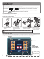
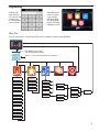
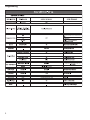
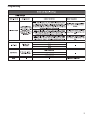
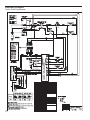
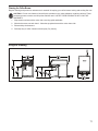
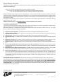
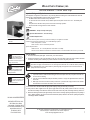
Wilbur Curtis Company, Inc.
Service Manual – Curtis Gold Cup
Important Safeguards/Symbols
This equipment is designed for commercial use. Any servicing other than cleaning and routine maintenance should be
performed by an authorized Wilbur Curtis Company Service Technician.
• DO NOT immerse the unit in water or any other liquid
• To reduce the risk of fire or electric shock, DO NOT open service panels. There are no user serviceable parts inside.
• Keep hands and other items away from hot areas of the unit during operation.
• Never clean with scouring powders or harsh chemicals.
Symbols:
WARNINGS – To help avoid personal injury
Important Notes/Cautions – from the factory
Sanitation Requirements
Model
CGC
This Curtis Gold Cup Unit is Factory Pre-Set and Ready to Go Right from the Box.
Following are the Factory Settings for your Coffee Brewing System:
• Brew Temperature = 200°F
• Brew Volume = Set to Vessel Requirement.
System Requirements:
• Water Source 20 – 90 PSI (Minimum Flow Rate of ½ GPM)
• Electrical: See attached schematic for standard model or visit www.wilburcurtis.com for your model.
CAUTION: Please use
this setup procedure
before attempting to use
this brewer. Failure to follow the
instructions can result in injury or the
voiding of the warranty.
IMPORTANT: Equipment
to be installed to comply
with applicable governmental plumbing/electrical codes
having jurisdiction.
CAUTION: DO NOT
connect this brewer to hot
water. The inlet valve is
not rated for hot water.
SETUP STEPS
1. The unit should be level (left to right - front to back), on a secure surface. 2. Connect the water line to the water inlet fitting on the rear of the unit. Water volume flow to the machine should be
consistent. Use tubing sized sufficiently to provide a minimum flow rate of one gallon per minute.
NOTE: A water filtration system must be used to help maintain trouble-free operation. In areas with extremely
hard water, we highly recommend the use of a Curtis approved water filter. For our full line of filters, please log
on to www.wilburcurtis.com. A water filtration system will greatly prolong the life of the unit and enhance the
quality and taste of the product.
NSF International requires the following water connection:
1. A quick disconnect or additional coiled tubing (at least 2x the depth of the unit) is required so that the unit
can be moved for cleaning.
2. This unit must be installed with adequate backflow protection to comply with applicable federal, state and
local codes.
3. Water pipe connections and fixtures directly connected to a portable water supply shall be sized, installed
and maintained in accordance with federal, state, and local codes.
3. Connect the unit to electrical outlet with appropriate amperage rating (see serial tag on machine).
4. Once power has been supplied to the unit, flip the toggle switch to the ‘ON’ position (located on the rear of the unit),
the water tank will begin to fill. When the water level in the tank reaches the probe, the heating element(s) will turn on.
5. Water in the heating tank will require approximately a half hour before reaching operating temperature (factory setting of
200°F). Where applicable, turn on the Universal Control Module (UCM). When the unit reaches operating temperature,
it will display “READY TO BREW”.
ISO 9001:2008 REGISTERED
WILBUR CURTIS CO., INC.
6913 West Acco Street
Montebello, CA 90640-5403
For the latest information go to
www.wilburcurtis.com
Tel: 800-421-6150
Fax: 323-837-2410
For the latest specifications and information go to www.wilburcurtis.com
Technical Support: 1-800-995-0417 M-F 5:30am-4:00pm PT
Email: [email protected]
1
Your Curtis Gold Cup Series is Factory Pre‑Set for Optimum Performance.
After connection to water and power; turn on the brewer at the rear toggle switch. You will hear a beep and the status lights will come on for a moment.
The screen will display
MODEL NUMBER
CONTROL BD NUMBER
When the proper level is reached
FILLING
. Next
HEATING
is displayed. Water will fill the tank (2-3 minutes depending on water flow rate).
will appear on the screen. It takes approximately 30 minutes to reach the set point temperature.
Control will display
READY TO BREW when temperature reaches the set point. The unit is now ready to brew.
COFFEE BREWING INSTRUCTIONS
1. Brewer should be ON (Confirm at the rear toggle switch). The screen should read Ready to Brew.
2. Place an empty cup under the brewcone.
3. Place a clean filter into the
brewcone.
4. Fill brewcone with the
proper amount of ground
coffee.
5. Slide the filled brewcone into
the brew rails on the brewer.
6. Select the desired coffee
size. Touch and hold for two
seconds to start brewing.
WARNING TO AVOID SCALDING, Do not remove brewcone while brew light is flashing.
Touch Screen Control Module
The touch screen turns on when power is available to the controller. The screen will contain standard control feature such as symbols and buttons. Pressing these elements with
your finger tip will activate the programming functions. The default screen, as well as some added control buttons are shown in the illustration below.
STATUS LIGHTS
BREW BUTTONS
CURTIS LOGO
TO ENTER PROGRAMMING
Tap Curtis logo 5 times to bring
up the ACCESS CODE screen.
CONTROL SYMBOLS
All of these symbols may
not be visible at one time.
2
RETURN TO HOME
SCROLL
RETURN TO PREVIOUS
Programming
ACCESS CODE
screen. Default is 1
2 3 4. Once the code
is entered, press
OK. The Main Menu
screen will appear.
MAIN MENU screen
contains five control
icons: CONTROL
SETTINGS, BREW
SETTINGS, MODEL
SELECT, SETTINGS
SUMMARY and EXIT.
Menu Tree
This chart explains how to enter the program mode and menu selections available from the MAIN MENU.
Tap "Curtis" Logo 5 Times
to Enter Programming Mode
Enter 1-2-3-4 to access the Main Menu. Press OK.
Te m p Se tti ngs
Se l e ct Button…
Filter Pre-Wet Time
Bre w By Vol um e
Ene rgy Sa vi ng
Dri p Out
S ounds
Hom e
Di a gnosti cs
Di spl a y Se tti ngs
Pre v - Ma i nt
Gemini
Gemini IF
S i ngl e
Thermopro
Tw i n
Milano
Gold Cup
One Ba tch
Tw o Ba tch
Ce ra m i c Cup
O
Three Batch
Paper Cup
Brew Counter
Passwords
Master Reset
Regional Settings
Home
3
Programming
4
Programming
5
Important Screen
Messages
WARNING MESSAGES - ALLOWS BREWING
MESSAGE DISPLAY
Component Failure
Service Required
1-(800)-000-0000x
WARNING DESCRIPTION
CAUSE
A Component has Failed
Current in one of the components is not within normal
range.
Maintenance Required
Service Required
1-(800)-000-0000x
Maintenance Required
Lime Scale Warning
Service Required
1-(800)-000-0000x
Scale Starting to Build Up
Water Level Probe
Low Water Flow Warning
Service Required
1-(800)-000-0000x
Low Water Flow
Brew count "Gallons Since Reset" exceeds
programmed Preventative Maintenance period
Water level probe resistance above warning
threshold (test value 23k Ohm)
If the Inlet valve remains on longer than 40
Seconds (during the brew cycle only) and repeats
TWICE during that brew cycle. It shall clear upon
the next brew and if the same low flow exists
again, it will re-appear.
ERROR MESSAGES - STOPS BREWING
MESSAGE DISPLAY
6
ERROR DESCRIPTION
CAUSE
Water Level Error
Service Required
1-(800)-000-0000x
Fill run error / Overflow
Sensor Error
Service Required
1-(800)-000-0000x
Open Sensor
Break in the temperature thermistor circuit or short
curcuit.
Over Temp. Error
Service Required
1-(800)-000-0000x
Excess Temperature
The sensor is reading that temperature in the
heating tank has risen above 210ºF, or sensor has
shorted to ground.
Lime Scale Error
Service Required
1-(800)-000-0000x
Probe
Water level probe resistance above error threshold
(test value 180kOhm)
Internal Error 1
Service Required
1-(800)-000-0000x
UPM-UCM Communication
The fill solenoid has either run for more than 10
minutes on the initial tank fill or 1.5 minutes in
normal operation
Break in the UPM-UCM Communication circuit.
Illustrated Parts
Main View
1
1
2
11
3
4
5
6
7
12
8
13
9
ITEM NO.
1
2
3
4
5
6
7
8
9
10
11
12
13
PART NO.
WC-10000*
WC-66081
WC-4868
WC-1809*
WC-3411
WC-66082
WC-3412
WC-66070
WC-66085
WC-61492
WC-61491
WC-3518*
WC-3503*
DESCRIPTION
CONTROL MODULE, TOUCH SCREEN G4
FRONT BEZEL
SCREW, 8-32x3/8 SOCKET HEAD HD SS
FAUCET, PS/HSP SERIES HOT WATER 1/2-20 UNF
BREW CONE ASSY, OPEN BREW CGC
FLAVOR CLIP, BREW CONE
BREW CONE ASSY, FP CGC (OPTIONAL)
DRIP TRAY
SCREEN, DRIP TRAY
COVER, TOP
COVER, BACK
LEG, 3/8”-16 x 1/2” LG. GLIDE
LEG, 3/8”-16 STUD SCREW BUMPER
* SUGGESTED PARTS TO STOCK
7
Illustrated Parts
Top Wrap
14
15
21
22
16
2
17
18
24
25
26
19
20
ITEM NO.
14
15
16
17
18
19
20
21
22
23
24
25
26
8
PART NO.
DESCRIPTION
WC- 589-101
TRANSFORMER, 120/230VAC - 24VAC 4.8VA w/LEADS & TRMNLS
WC- 817*
VALVE, DUMP RIGHT 120V-12W
WC- 889*
VALVE, DUMP LEFT 120V-12W
WC-2962
FITTING, SPRAYHEAD
WC-4320
O’RING, 1/2” I.D.
WC-4213
NUT, 5/8 LOCK PLATED
WC-29025*
SPRAYHEAD, ASSY AFS-PURPLE
WC- 826L*
VALVE, INLET 1.15GPM 120Vac 10W
WC-2401
ELBOW, 3/8 NPT x 1/4 FLARE PLTD
WC-10001*
UNIVERSAL POWER MODULE - G4
WC-8556*
HEATSINK and TRIAC ASSY 40A 600V
WC-13443
HARNESS ASSY COMPLETE CGC
WC-10008K
UNIVERSAL HOST ADAPTER, USB (OPTIONAL)
* SUGGESTED PARTS TO STOCK
Illustrated Parts
Heating Tank
27
28
29
30
35
31
32
33
36
34
ITEM NO.
27
28
29
30
31
32
33
34
35
36
PART NO.
DESCRIPTION
WC-5853-102 COVER, TOP HEATING TANK
WC-43062*
GASKET, TANK LID
WC-5502*
PROBE, WATER LEVEL
WC-5310
TUBE, 5/16 ID x 1/8W SILICONE GEN USE
WC-4394
GUARD, SHOCK/HEATING ELEMENT
WC- 522*
THERMOSTAT, HI LIMIT HEATER DPST 277V-40A
WC-1438-101* SENSOR, TEMPERATURE TANK
WC-43055
GUARD, SHOCK RESET THERMOSTAT
WC-54324DV* TANK ASSY 1.73 GAL, 120/220V, (2) 1450W ELEMENT
WC- 917-04*
ELEMENT, HEATING 1.45KW 120V W/JAM NUTS & SILICONE WSHRS
* SUGGESTED PARTS TO STOCK
9
Electrical Schematic
Curtis Gold Cup Brewer
10
Cleaning the Coffee Brewer
Regular cleaning and preventive maintenance is essential in keeping your coffee brewer looking and working like new.
CAUTION – Do not use cleansers, bleach liquids, powders or any other substance containing chlorine. These
products promote corrosion and will pit the stainless steel. USE OF THESE PRODUCTS WILL VOID THE
WARRANTY.
1. Wipe exterior surfaces with a moist cloth, removing spills and debris.
2. Slide the brewcone out and clean it. Clean the sprayhead area with a moist clean cloth.
3. Rinse and dry the brewcone.
4. Drain drip tray of coffee. Wash out the drip tray. Dry the tray.
Rough-In Drawing
11
Product Warranty Information
The Wilbur Curtis Company certifies that its products are free from defects in material and workmanship under normal use. The following limited
warranties and conditions apply:
3 Years, Parts and Labor, from Original Date of Purchase on digital control boards.
2 Years, Parts, from Original Date of Purchase on all other electrical components, fittings and tubing.
1 Year, Labor, from Original Date of Purchase on all electrical components, fittings and tubing.
Additionally, the Wilbur Curtis Company warrants its Grinding Burrs for Forty (40) months from date of purchase or 40,000 pounds of coffee,
whichever comes first. Stainless Steel components are warranted for two (2) years from date of purchase against leaking or pitting and replacement parts are warranted for ninety (90) days from date of purchase or for the remainder of the limited warranty period of the equipment in which
the component is installed.
All in-warranty service calls must have prior authorization. For Authorization, call the Technical Support Department at 1-800-995-0417. Effective
date of this policy is April 1, 2003.
Additional conditions may apply. Go to www.wilburcurtis.com to view the full product warranty information.
CONDITIONS & EXCEPTIONS
The warranty covers original equipment at time of purchase only. The Wilbur Curtis Company, Inc., assumes no responsibility for substitute replacement parts installed on Curtis equipment that have not been purchased from the
Wilbur Curtis Company, Inc. The Wilbur Curtis Company will not accept any responsibility if the following conditions are not met. The warranty
does not cover and is void under the following circumstances:
1) Improper operation of equipment: The equipment must be used for its designed and intended purpose and function.
2) Improper installation of equipment: This equipment must be installed by a professional technician and must comply with all local electrical,
mechanical and plumbing codes.
3) Improper voltage: Equipment must be installed at the voltage stated on the serial plate supplied with this equipment.
4) Improper water supply: This includes, but is not limited to, excessive or low water pressure, and inadequate or fluctuating water flow
rate.
5) Adjustments and cleaning: The resetting of safety thermostats and circuit breakers, programming and temperature adjustments are the
responsibility of the equipment owner. The owner is responsible for proper cleaning and regular maintenance of this equipment.
6) Damaged in transit: Equipment damaged in transit is the responsibility of the freight company and a claim should be made with the carrier.
7) Abuse or neglect (including failure to periodically clean or remove lime accumulations): Manufacturer is not responsible for variation
in equipment operation due to excessive lime or local water conditions. The equipment must be maintained according to the manufacturer’s
recommendations.
8) Replacement of items subject to normal use and wear: This shall include, but is not limited to, light bulbs, shear disks, “0” rings, gaskets,
silicone tube, canister assemblies, whipper chambers and plates, mixing bowls, agitation assemblies and whipper propellers.
9) Repairs and/or Replacements are subject to our decision that the workmanship or parts were faulty and the defects showed up under normal
use. All labor shall be performed during regular working hours. Overtime charges are the responsibility of the owner. Charges incurred by
delays, waiting time, or operating restrictions that hinder the service technician’s ability to perform service is the responsibility of the owner
of the equipment. This includes institutional and correctional facilities. The Wilbur Curtis Company will allow up to 100 miles, round trip, per
in-warranty service call.
RETURN MERCHANDISE AUTHORIZATION: All claims under this warranty must be submitted to the Wilbur Curtis Company Technical
Support Department prior to performing any repair work or return of this equipment to the factory. All returned equipment must be repackaged
properly in the original carton. No units will be accepted if they are damaged in transit due to improper packaging. NO UNITS OR PARTS WILL
BE ACCEPTED WITHOUT A RETURN MERCHANDISE AUTHORIZATION (RMA). RMA NUMBER MUST BE MARKED ON THE CARTON
OR SHIPPING LABEL. All in-warranty service calls must be performed by an authorized service agent. Call the Wilbur Curtis Technical Support Department to find an agent near you.
11/1/[email protected] . ECN 13598
7/27/[email protected] . EDR 7960
WILBUR CURTIS CO., INC.
6913 Acco St., Montebello, CA 90640-5403 USA
Phone: 800/421-6150 Fax: 323-837-2410
Technical Support Phone: 800/995-0417 (M-F 5:30A - 4:00P PST)
Web Site: www.wilburcurtis.com
E-Mail: [email protected]
10/11 . F-3821 rev A