1
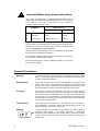
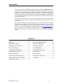
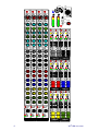
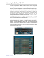
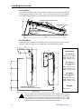
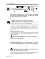
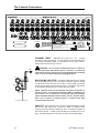
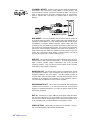
MixWizard WZ312M
16 Input 12 Mix Monitor Console
USER GUIDE
Publication AP6769
Limited One Year Warranty
This product is warranted to be free from defects in materials or workmanship for
a period of one year from the date of purchase by the original owner.
To ensure a high level of performance and reliability for which this equipment has
been designed and manufactured, read this User Guide before operating. In the
event of a failure, notify and return the defective unit to ALLEN&HEATH Limited
or its authorised agent as soon as possible for repair under warranty subject to
the following conditions
Conditions Of Warranty
1. The equipment has been installed and operated in accordance with the
instructions in this User Guide
2. The equipment has not been subject to misuse either intended or accidental,
neglect, or alteration other than as described in the User Guide or Service
Manual, or approved by ALLEN&HEATH.
3. Any necessary adjustment, alteration or repair has been carried out by
ALLEN&HEATH or its authorised agent.
4. This warranty does not cover fader wear and tear.
5. The defective unit is to be returned carriage prepaid to ALLEN&HEATH or its
authorised agent with proof of purchase.
6. Units returned should be packed to avoid transit damage.
In certain territories the terms may vary. Check with your ALLEN&HEATH agent
for any additional warranty which may apply.
This product complies with the European Electromagnetic
Compatibility directives 89/336/EEC & 92/31/EEC and the
European Low Voltage Directives 73/23/EEC & 93/68/EEC.
This product has been tested to EN55103 Parts 1 & 2 1996 for use in
Environments E1, E2, E3, and E4 to demonstrate compliance with the
protection requirements in the European EMC directive 89/336/EEC.
During some tests the specified performance figures of the product
were affected. This is considered permissible and the product has
been passed as acceptable for its intended use. Allen & Heath has a
strict policy of ensuring all products are tested to the latest safety and
EMC standards. Customers requiring more information about EMC and
safety issues can contact Allen & Heath.
NOTE: Any changes or modifications to the console not approved by
Allen & Heath could void the compliance of the console and therefore
the users authority to operate it.
WZ312M User Guide AP6769 Issue 1
Copyright © 2007 Allen & Heath Limited. All rights reserved
ALLEN&HEATH Limited
Kernick Industrial Estate, Penryn, Cornwall, TR10 9LU, UK
http://www.allen-heath.com
2
WZ312M User Guide
Important Safety Instructions
WARNINGS -
Read the following before proceeding :
CAUTION
ATTENTION: RISQUE DE CHOC ELECTRIQUE – NE PAS OUVRIR
Read instructions:
Retain these safety and operating instructions for future reference. Adhere
to all warnings printed here and on the console. Follow the operating
instructions printed in this User Guide.
Do not remove cover:
Operate the console with its covers correctly fitted. Disconnect mains
power by unplugging the power cord if the cover needs to be removed for
setting internal options. Refer this work to competent technical personnel
only.
Power sources:
Connect the console to a mains power unit only of the type described in
this User Guide and marked on the rear panel. Use the power cord with
sealed mains plug appropriate for your local mains supply as provided with
the console. If the provided plug does not fit into your outlet consult your
service agent for assistance.
Power cord routing:
Route the power cord so that it is not likely to be walked on, stretched or
pinched by items placed upon or against it.
Grounding:
Do not defeat the grounding and polarisation means of the power cord
plug. Do not remove or tamper with the ground connection in the power
cord.
WARNING: This equipment must be earthed.
Water and moisture:
To reduce the risk of fire or electric shock do not expose the console to
rain or moisture or use it in damp or wet conditions. Do not place
containers of liquids on it which might spill into any openings.
Ventilation:
Do not obstruct the ventilation slots or position the console where the air
flow required for ventilation is impeded. If the console is to be operated in
a rack unit or flightcase ensure that it is constructed to allow adequate
ventilation.
Heat and vibration:
Do not locate the console in a place subject to excessive heat or direct
sunlight as this could be a fire hazard. Locate the console away from any
equipment which produces heat or causes excessive vibration.
Servicing:
Switch off the equipment and unplug the power cord immediately if it is
exposed to moisture, spilled liquid, objects fallen into the openings, the
power cord or plug become damaged, during lightening storms, or if
smoke, odour or noise is noticed. Refer servicing to qualified technical
personnel only.
Installation:
Install the console in accordance with the instructions printed in this User
Guide. Do not connect the output of power amplifiers directly to the
console. Use audio connectors and plugs only for their intended purpose.
WZ312M User Guide
3
Important Mains plug wiring instructions.
The console is supplied with a moulded mains plug fitted to the AC
mains power lead. Follow the instructions below if the mains plug has
to be replaced. The wires in the mains lead are coloured in
accordance with the following code:
WIRE COLOUR
TERMINAL
European
USA/Canada
L
LIVE
BROWN
BLACK
N
NEUTRAL
BLUE
WHITE
E
EARTH GND
GREEN & YELLOW
GREEN
The wire which is coloured Green and Yellow must be connected to the
terminal in the plug which is marked with the letter E or with the Earth
symbol. This appliance must be earthed.
The wire which is coloured Blue must be connected to the terminal in
the plug which is marked with the letter N.
The wire which is coloured Brown must be connected to the terminal in
the plug which is marked with the letter L.
Ensure that these colour codes are followed carefully in the event of
the plug being changed.
General Precautions
4
Damage :
To prevent damage to the controls and cosmetics avoid placing heavy
objects on the control surface, scratching the surface with sharp objects,
or rough handling and vibration.
Environment :
Protect from excessive dirt, dust, heat and vibration when operating and
storing. Avoid tobacco ash, smoke, drinks spillage, and exposure to rain
and moisture. If the console becomes wet, switch off and remove mains
power immediately. Allow to dry out thoroughly before using again.
Cleaning :
Avoid the use of chemicals, abrasives or solvents. The control panel is
best cleaned with a soft brush and dry lint-free cloth. The faders, switches
and potentiometers are lubricated for life. The use of electrical lubricants
on these parts is not recommended. The fader and potentiometer knobs
may be removed for cleaning with a warm soapy solution. Rinse and allow
to dry fully before refitting them.
Transporting :
The console may be transported as a free-standing unit or mounted in a
rack or flightcase. Protect the controls from damage during transit. Use
adequate packing if you need to ship the unit.
Hearing :
To avoid damage to your hearing do not operate any sound system at
excessively high volume.
This applies particularly to close-to-ear
monitoring such as headphones and in-ear systems. Continued exposure
to high volume sound can cause frequency selective or wide range
hearing loss.
WZ312M User Guide
Introduction
Welcome to the Allen & Heath WZ3, the latest generation of the popular MixWizard series of
compact audio mixing consoles. We have tried to keep this user guide brief and to the point.
Please read it fully before starting. Included is information on installing, connecting and
operating the console, panel drawings, system block diagram and technical specification.
For further information on the basic principles of audio system engineering, please refer to
one of the specialist publications and resources available from bookshops, audio equipment
dealers and the Internet.
Whilst we believe the information in this guide to be reliable we do not assume responsibility
for inaccuracies. We also reserve the right to make changes in the interest of further product
development.
We are able to offer further product support through our world-wide network of approved
dealers and service agents. You can also access our Web site on the Internet for
information on our full product range, our company pedigree, assistance with your technical
queries, our contact details or simply to chat about matters audio ( www.allen-heath.com )To
help us provide the most efficient service please keep a record of your console serial
number, and date and place of purchase to be quoted in any communication regarding this
product.
Contents
Warranty ................................................ 2
Connector Panel Layouts ....................12
General Precautions.............................. 4
Console Connectors............................13
Introduction to this Guide...................... 5
The Input Channels .............................14
Front Panel Layout ................................ 6
The Mix Masters...................................16
Introducing the MixWizard .................... 7
The Engineer’s Monitor .......................17
Installing the Console............................ 8
Gain Structure......................................18
Connecting Power................................. 9
Specifications ......................................19
Connecting a Backup Supply ............... 9
System Block Diagram ........................21
Connection Pinouts and Cables ......... 10
Cue Sheet ............................................22
Audio Connections .............................. 11
WZ312M User Guide
5
LAMP
PHONES
+48V
+48V
PAD
PAD
(LINE)
0 20
30
40
0 20
30
40
- 10 10
60 40
700
500Hz
HM
-15
70
180
+15
70
1k
-15
+15
OO
MIX
2
OO
+15
MIX
ST
MIX
OO
L
MIX
MIX
MIX
ST
ST
ST
ST
MIX
3
OO
+6
C
PAN
MIX
4
3
OO
+6
C
PAN
MIX
4
L
OO
L
MIX
OO
OO
MIX
6
OO
+6
OO
L
+6
OO
OO
OO
+6
C
PAN
MIX
MIX
8
L
MIX
8
L
+6
OO
+6
OO
L
+6
OO
OO
+6
C
PAN
PAN
MIX
L
PAN
L
MIX
10
+6
OO
R
+6
OO
+6
OO
MIX
ST
ST
ST
MIX
11
OO
+6
C
PAN
MIX
12
L
OO
MIX
CH TRIM
L
SIG
CH TRIM
PFL
+6
OO
SIG
PFL
+6
OO
OO
R
+6
C
+6
OO
AFL
PK!
PK!
PK!
PK!
R
5
5
5
5
10
10
10
10
20
20
20
20
30
30
30
30
OO
OO
OO
OO
5
6
7
8
STEREO
OO
PAN
L
R
STEREO
+6
C
+6
OO
+6
C
ST
MIX
OO
R
MUTE
MUTE
AFL
AFL
PAN
12
+6 R
OO
L
CH TRIM
PFL
PK!
PK!
PK!
SIG
SIG
SIG
SIG
+6 R
OO
5
5
5
5
0
0
0
0
MUTE
CH TRIM
+6
OO
PK!
+6
C
MUTE
SIG
MUTE
AFL
+6
C
11
L
PK!
MUTE
+6
OO
PK!
SIG
PFL
5
5
5
5
10
10
10
10
20
20
20
20
30
30
30
30
OO
OO
OO
OO
10
11
9
STEREO
6
4
STEREO
MIX
PAN
+6
OO
PK!
OO
10
OO
+6 R
OO
+6
+6 R
PAN
L
MIX
MUTE
+6
OO
PAN
12
MUTE
PK!
+6
C
PAN
+6 R
+6
C
11
12
OO
OO
L
MIX
STEREO
9
R
MIX
11
3
C
OO
R
10
L
2
8
ST
10
OO
+6 R
PAN
L
ST
MIX
OO
0
ST
+6
OO
0
ST
C
30
OO
+6
0
MIX
9
OO
20
30
0
MIX
+6
20
30
ST
MIX
C
20
30
SIG
MIX
OO
20
7
R
9
5
10
5
MIX
9
5
SIG
R
8
R
0
10
6
R
+6
5
0
5
ST
C
5
0
SIG
MIX
7
OO
5
0
5
ST
PAN
5
SIG
ST
+6
SIG
5
ST
C
SIG
5
5
MIX
OO
SIG
MIX
MIX
PAN
SIG
10
POST
PRE
MIX
7
PK!
5
OO
OO
L
MIX
7
PK!
10
C
PAN
+6 R
6
R
PK!
+15
POST
PRE
MIX
6
L
L
ST
+6
C
PAN
PK!
4
5
ST
+6
C
PAN
MIX
MIX
5
ST
MIX
+6
C
POST
PRE
MIX
5
OO
PAN
+6 R
POST
PRE
AFL
3
4
+6 R
MUTE
AFL
1
L
MIX
3
OO
PAN
+6 R
OO
MUTE
EQ IN
2
+6 R
R
+15
-15
+6
C
10
1k
1
OO
0
PFL
250
MIX
PAN
EXT IN
400
-15
+15
MONITOR
+15
35Hz
LF
2
L
180
EQ IN
ST
+6
C
PAN
70
LM
1
+6 R
OO
-15
-15
2
L
1k
L
MONO
15k
45
400
35Hz
+15
-15
250
+16
+9
+6
+3
0
-3
-6
-9
-12
-16
-20
-30
6k
500Hz
+15
MIX
ST
+6
C
180
700
HM
+16
+9
+6
+3
0
-3
-6
-9
-12
-16
-20
-30
3k +15
4k
1k
15k
EQ IN
1
PAN
70
LF
MIX
ST
500Hz
45
LM
+15
-15
1
MIX
250
-15
6k
-15
1k
EQ IN
MIX
HM
400
-15
LF
700
+15
35Hz
LM
+15
180
60 40
HPF
3k +15
4k
1k
15k
45
400
-15
LF
500Hz
50
- 10 10
HF
-15
6k
-15
250
35Hz
LM
60 40
HPF
700
HM
40
GAIN
- 10 10
3k +15
4k
1k
15k
45
0
-15
6k
0 20
30
50
HF
3k +15
4k
1k
40
HPF
HF
-15
(LINE)
GAIN
50
HPF
HF
k
0 20
GAIN
50
60 40
PAD
(LINE)
30
POWER
+48V
PAD
(LINE)
GAIN
- 10 10
+48V
12
STEREO
WZ312M User Guide
Introducing the MixWizard WZ312M
The Allen & Heath MixWizard WZ312M Is a dedicated monitor console. With 16 mic/line
channels feeding 12 mixes in a compact 19” rack mount frame it is ideal for personal
monitoring systems touring with a show or installed on stage where space is tight.
Each of the 16 mic/line channels features a 4 band semi-parametric EQ, high pass filter, 12
mix sends globally switched in pairs for mono or stereo operation, individual phantom power,
rotary channel trim control, mute and PFL monitoring. Each of the 12 mix masters includes
a fader, mute and AFL monitoring, stereo mode selector, insert and differentially balanced
XLR output. Channel and mix master inserts can be used for patching in outboard signal
processors such as compressors, noise gates and graphic EQ. Comprehensive metering
and stereo/mono PFL/AFL headphones/local monitoring, external monitor input, dual
redundant backup supply input, and a lamp socket are provided. An option is available to
link two consoles together to expand the number of inputs to 32.
The WZ312M features a built-in XLR mic splitter. This means that inputs can be plugged
into the console on stage and simultaneously linked to the multi-core feeding the front-ofhouse console without the need for an external mic splitter.
The MixWizard Series is built with individual circuit cards, potentiometers nutted to the panel
for absolute strength, an all steel chassis, and no compromise circuit design ensuring the
finest sonic performance. The console can be operated free standing or in a 19” rack or
flightcase. It is supplied with protective side trims fitted. These can be removed for rack
mounting. The rear connector pod can be rotated for rear facing or underside connectors
when rack mounted.
Accessories available include the Allen & Heath MPS12 backup power supply and LEDlamp
gooseneck lamp with built-in dimmer.
WZ312M User Guide
7
Installing the Console
Free Standing
The console is supplied ready for free standing operation with its side trims fitted and
connector pod positioned for rear access. If you are converting from rack to free standing
then make sure the pod is correctly rotated and secured, and the side trims fitted as shown:
55
FIT SIDE TRIMS - 4x M4 POZI SCREWS PER SIDE
194
CONSOLE WIDTH = 507mm
12
58
RELEASE M4 POZI SCREW EACH SIDE
ROTATE POD AND REFIT SECURING SCREWS
514
530
19” Rack Mount
For rack mounting, remove the two side trims and rotate the pod into the connector position
preferred. Allow enough space for the cables and connectors behind the console.
193
Dimensions
122
444
(10U)
497
(11.2U)
101.6
193
Free Standing
Width 507 mm (20”)
Depth 530 mm (21”)
Height 194 mm (7.7”)
Rack Mount
Top Connectors
11.2U
Width 483 mm (19”)
Depth 195 mm (1.7”)
Height 497 mm (19.6”)
101.6
165.1
Rack Mount
Rear Connectors
10U
Width 483 mm (19”)
Depth 125mm (5.1”)
Height 444 mm (17.5”)
Weights
37.7
SECURE IN RACK USING 8x M6 BOLTS
USE PLASTIC CUP WASHERS TO PROTECT THE PANEL
12kg (27 lbs)
482.6 (19" RACK)
Do not transport the console with its connector pod securing screws removed.
Do not attempt to remove the connector pod from the console. Do not obstruct
the ventilation slots. Allow adequate space around the console for air flow. If the
side trims are to be removed, do not refit their fixing screws to the unit. Retain
and store these in case the trims need to be refitted in the future.
8
WZ312M User Guide
Connecting Power
FUSE
CAUTION
T630mA L 250V 20mm
RISK OF ELECTRIC SHOCK
DO NOT OPEN
EXTERNAL DC IN
AC MAINS IN ~
100 - 240V~ 47-63Hz 45W MAX
OFF
ON
0
I
AVIS: RISQUE DE CHOC ELECTRIQUE - NE PAS OUVRIR.
CAUTION: FOR CONTINUED PROTECTION AGAINST RISK OF FIRE REPLACE FUSE WITH SAME TYPE AND RATING.
ATTENTION: REMPLACER LE FUSIBLE AVEC UN DES MEMES CARACTERISTIQUES.
WARNING: TO REDUCE THE RISK OF ELECTRIC SHOCK DO NOT EXPOSE THIS APPARATUS TO RAIN OR MOISTURE.
REFER SERVICING TO QUALIFIED SERVICE PERSONNEL.
RECOMMENDED ALLEN&HEATH POWER SUPPLY
REFER TO USER GUIDE FOR DETAILS
ENGINEERED IN ENGLAND BY ALLEN & HEATH LIMITED
WARNING: THIS APPARATUS MUST BE EARTHED
Serial No.
Read and understand the Important Safety Instructions printed at the start of this guide,
and the warnings printed on the rear of the console. Check that your local mains supply is
within the 100-240V operating voltage range allowed. Check that the correct mains lead
with moulded plug has been supplied with your console. Make sure that the IEC mains plug
is pressed fully into the panel socket before switching on.
Grounding
The connection to ground in an audio system is important for two reasons:
1.
SAFETY - To protect the operator from high voltage electric shock, and
2. AUDIO PERFORMANCE - To minimise the effect of ground (earth) loops which result in
audible hum and buzz, and to shield the audio signals from interference.
For safety it is important that all equipment grounds are connected to mains ground so that
exposed metal parts are prevented from carrying high voltage which can injure or even kill
the operator. Do not disconnect the ground connection in the mains lead. It is
recommended that the system engineer check the continuity of the safety ground from all
points in the system including microphone bodies, turntable chassis, equipment cases, rack
metalwork and so on.
Switching the console on and off
It is good practice to turn power amplifiers off before switching the console and any other
connected equipment on or off. This prevents any unexpected clicks or thumps when the
equipment is powered up.
Turn amplifiers, powered speakers and in-ear systems on last and off first.
To turn the console on, press the ON/OFF switch next to the IEC mains input socket. To
turn the console off, press this switch again.
Connecting a backup supply
A socket is included for plugging in an optional backup power supply. This provides the
reassurance of power supply dual redundancy, a feature usually found only in expensive top
end consoles. The console uses diode combining technology so that both supplies can be
powered at the same time. One will automatically take over should the other stop working.
The recommended backup supply for the MixWizard is the Allen & Heath MPS12 power unit.
Refer to the user guide which comes with this supply.
Only plug the recommended Allen & Heath power unit into this socket. Do not
attempt to modify any other power unit to work with the console. Do not attempt to modify or
extend the DC power cable that comes with the supply.
The console can work with just the internal supply powered by mains, or just the backup
supply, or with both powered at the same time. To ensure uninterrupted performance in the
unlikely event of a failure, we recommended that both supplies are powered.
WZ312M User Guide
9
10
WZ312M User Guide
L- 37
R- 36
GRP 1- 35
GRP 2- 34
GRP 3- 33
GRP 4- 32
AUX 1- 31
AUX 2- 30
AUX 3- 29
AUX 4- 28
AUX 5- 27
AUX 6- 26
PFL- 25
AFL- 24
nc 23
nc 22
nc 21
nc 20
19 0V (CHS)
18 L+
17 R+
16 GRP 1+
15 GRP 2+
14 GRP 3+
13 GRP 4+
12 AUX 1+
11 AUX 2+
10 AUX 3+
9 AUX 4+
8 AUX 5+
7 AUX 6+
6 PFL+
5 AFL+
4 nc
3 PFL DC
2 AFL DC
1 0V (PAFL)
Audio Connections
The MixWizard uses professional grade 3 pin XLR and 1/4" TRS (3 pole) jack sockets. To
ensure best performance, we recommend that you use high quality audio cables and
connectors, and take time to check for reliable and accurate cable assembly. It is well
known that most audio system problems are due to faulty or sub standard interconnecting
leads. The following mating plugs may be used to connect audio signals to the console:
Avoid reversing + and - on balanced connections as this will result in reversed polarity (out
of phase) signals which may cause signal cancellation effects.
Where long cables runs are required, balanced interconnections should be used. However,
line level interconnections between more affordable 2-wire (signal, ground) unbalanced
equipment and the console are unlikely to cause problems if the cables are kept shorter than
10 meters or so. Refer to the wiring diagrams on the opposite page.
Dealing with Ground Loops, Buzz and Interference
For optimum performance all audio signals should be referenced to a solid, noise-free
ground (earth) point, frequently referred to as the ‘star point’ or ‘clean earth’.
A ground loop is created when potential differences exist between grounds at different
points in the system, and the signal has more than one path to ground. In most cases
ground loops do not result in audible problems. Should you experience hum or buzz caused
by a ground loop, check first that each piece of equipment has its own separate path to
ground. If so, operate ground lift switches on connected equipment in accordance with the
instruction manuals. Alternatively disconnect the cable screen at the destination end only.
This breaks the offending loop while keeping the signal shielding down the length of cable.
WARNING For operator safety do not remove the ground (earth) connection
in the power lead of the console or connected equipment.
To avoid interference pickup keep audio cables away from mains power units and cables,
thyristor dimmer units, computer equipment and mobile phones. Where this cannot be
avoided, cross the cables at right angles to minimise interference
A note about balanced connections
A differentially balanced connection has two signal wires, signal + (hot) and signal - (cold)
and a shield. The signal source generates positive going polarity down the + wire and
negative polarity down the – wire. The destination input stage accepts the + signal on its
non-inverting (+) input pin, but it inverts the – signal, adding it to the + signal. The result is
that the wanted signal is boosted. Now examine what happens when unwanted interference
(hum and noise) is induced into the cable. The noise is induced equally and with the same
polarity into both wires. At the destination input the – wire signal gets inverted and added to
the + signal. Because the polarity is the same on both input wires the noise cancels itself
out at this input. For this interference rejection to work it is important that the source, the
cable and the destination input are all balanced. Balancing provides greatest advantage
with low level signals such as those produced by microphones.
An impedance balanced output provides similar interference rejection, but without the signal
drive on the - wire. It does not generate a negative polarity signal at its – output. Instead,
the – wire has no signal but is held at the same impedance as the + wire. This means that
both wires pick up the noise equally resulting in cancellation as described above.
WZ312M User Guide
11
The Console Connectors
ALLEN&HEATH
INSERT
INSERT
INSERT
INSERT
INSERT
INSERT
INSERT
IN
IN
IN
IN
IN
IN
SPLIT
SPLIT
SPLIT
SPLIT
SPLIT
SPLIT
16
15
14
EXT MONITOR IN
R
L
13
R
MONITOR
OUT
L
12
11
MixWizard WZ3 12M
GROUND LIFT
INSERT
INSERT
INSERT
INSERT
INSERT
INSERT
INSERT
INSERT
INSERT
IN
IN
IN
IN
IN
IN
IN
IN
IN
IN
SPLIT
SPLIT
SPLIT
SPLIT
SPLIT
SPLIT
SPLIT
SPLIT
SPLIT
SPLIT
10
9
INSERT
7
6
INSERT
INSERT
5
4
INSERT
3
INSERT
INSERT
INSERT
11
10
9
8
7
6
5
4
3
2
1
OUT
OUT
OUT
OUT
OUT
OUT
OUT
OUT
OUT
OUT
OUT
OUT
INSERT
FUSE
CAUTION
BACKUP SUPPLY
INSERT
1
12
EXTERNAL DC IN
INSERT
2
INSERT
USER OPTION PORT A
INSERT
8
T630mA L 250V 20mm
RISK OF ELECTRIC SHOCK
DO NOT OPEN
AC MAINS IN ~
100 - 240V~ 47-63Hz 45W MAX
AVIS: RISQUE DE CHOC ELECTRIQUE - NE PAS OUVRIR.
USER OPTION PORT B
CAUTION: FOR CONTINUED PROTECTION AGAINST RISK OF FIRE REPLACE FUSE WITH SAME TYPE AND RATING.
ATTENTION: REMPLACER PAR UN FUSIBLE STRICTEMENT IDENTIQUE EN VALEURS.
WARNING: TO REDUCE THE RISK OF ELECTRIC SHOCK DO NOT EXPOSE THIS APPARATUS TO RAIN OR MOISTURE.
REFER SERVICING TO QUALIFIED SERVICE PERSONNEL.
ONLY USE RECOMMENDED ALLEN&HEATH POWER SUPPLY.
REFER TO USER GUIDE FOR DETAILS.
This device complies with Part 15 of the FCC Rules. Operation is subject to the following two conditions:
(1) this device may not cause harmful interference, and
(2) this device must accept any interference received, including interference that may cause undesired operation.
ENGINEERED IN ENGLAND BY ALLEN & HEATH LIMITED
WARNING: THIS APPARATUS MUST BE EARTHED
Serial No.
CHANNEL INPUT
Balanced XLR input pin 2 hot. Accepts
microphone or line level signals. For very hot mic or for line signals press
the channel PAD (LINE) switch. For unbalanced sources use a cable or
adapter that connects XLR pin 3 to pin 1.
48V
IN
2= +
LIFT
SPLIT
To other channels
WARNING: Do not connect unbalanced sources or cables to
the XLR input when 48V phantom power is selected. To avoid loud
clicks always turn the channel off by pressing MUTE when switching
+48V on or off, and when plugging or unplugging cables.
BUILT-IN MIC SPLITTER A passive splitter passes each channel
XLR input directly through to an XLR output to send the signal to another
console such as Front-of-House or recording. The mic signal can feed the
monitor and the FOH console at the same time. Connect the split outputs
to the multicore feeding the FOH console using XLR cables.
NOTE: Phantom power can be switched from either the monitor or
the FOH console. If switched from FOH then make sure GND LIFT is
not selected. If it is necessary to select GND LIFT then phantom
power should be switched from the monitor console. No harm will be
done to the consoles if phantom power is switched from both
consoles at the same time.
GND LIFT Disconnects the pin 1 ground connection between the input
XLR and the split output XLR. Press this if there is a problem with a
venue ground loop causing audible hum when connecting the splitter to
the second console. A single ground lift switch is provided next to CH1
input. This affects the ground connection to all the channel split outputs.
12
WZ312M User Guide
OFF
ON
0
I
SEND
RETURN
INSERT
CHANNEL INSERT A single 3-pole TRS jack carries the unbalanced
TIP
RING
insert signal. Tip = send, Ring = return, Sleeve = common ground. The
channel insert is post-HPF, pre-EQ and operates at 0dBu. Use these to
patch in line level signal processing equipment such as compressors,
gates or outboard EQ. The wiring of a suitable cable is shown in the
diagram:
MIX INSERT Each mix is provided with an insert socket for patching in
an outboard signal processor. When working with stage speakers this is
typically a 31 band graphic or a multi band parametric EQ used for ringing
out feedback or tuning the speaker response. When working with in-ear
systems this may be a dynamics processor with limiter to protect the in-ear
user’s ears from unexpected signal peaks. AFL monitors the signal after
the insert so that the engineer can listen to the effect of the processor. A
single 3-pole TRS jack carries the unbalanced insert signal for each mix
output. Tip = send, Ring = return, Sleeve = common ground. The insert is
pre-fader and operates at a nominal -2dBu line level.
MIX OUT The 12 mix outputs are provided on balanced XLR, pin 2 hot.
These produce +4dBu when the meters read ‘0’. The mix outputs feed the
stage monitors, typically wedge loudspeakers and in-ear personal
monitoring systems. They can also be used as effects sends, recording
feeds and for other special requirements.
MONITOR OUT The console stereo monitor is simultaneously sent to
the headphones amplifier, a pair of balanced XLR outputs and a pair of
impedance balanced TRS jack outputs. The XLR output operates at
nominal +4dBu, the TRS jack at -2dBu. The XLR and jack outputs can be
connected to the engineer’s local speaker or in-ear monitoring systems.
The output may be switched for mono or stereo operation.
HEADPHONES OUT The console is provided with two headphones
sockets on the front panel – a ¼” TRS jack and a mini 3.5mm jack for
plugging in standard headphones or monitor ear pieces similar to those
worn by the performers.
EXT IN Unbalanced ¼” jacks, 0dBu line level signal. Feeds the stereo
AFL mix when switched on. For mono signals, plug into the left input only.
Use this input to add an external signal such as the monitor output from an
in-ear transmitter rack or remote talkback to the engineers monitor.
USER OPTION Blank plates are fitted here as standard. The SysLink II console expander option kit may be fitted here.
WZ312M User Guide
13
The Input Channels
+48V Switches +48VDC to the channel input XLR for powering
microphones or DI boxes that need phantom power. The power is
current limited through 6k8 ohm resistors to pins 2 and 3.
+48V
PAD
(LINE)
0 20
30
40
GAIN
G
50
60 40
- 10 10
WARNING: Do not connect unbalanced sources or cables
to inputs with phantom power selected. To avoid loud clicks
always mute the channel before switching +48V on or off and
when plugging or unplugging microphones.
HPF
HF
-15
3k +15
4k
1k
700
6k
500Hz
HM
15k
H
PAD (LINE) Press to switch in a 20dB attenuator pad between the
-15
70
180
250
45
LM
LF
channel XLR input and the preamp.
microphone signals.
+15
400
35Hz
1k
-15
+15
-15
L
+15
EQ IN
MIX
M
1
ST
MIX
OO
M
2
L
+6 R
OO
MIX
M
3
ST
MIX
OO
+6
C
PAN
M
4
L
+6 R
OO
POST
PRE
MIX
M
5
ST
MIX
OO
+6
C
PAN
M
6
L
+6
OO
R
MIX
M
7
ST
MIX
OO
+6
C
PAN
M
8
L
+6
OO
R
M
MIX
9
ST
MIX
OO
+6
C
PAN
+6
OO
R
MIX
M
11
ST
MIX
Switches in the channel high pass filter. This attenuates
frequencies below 80Hz by 12dB per octave. The filter is pre-insert,
pre-EQ. Select the HPF to reduce low frequency noise such as
microphone popping, stage noise and tape transport rumble.
EQ A 4-band semi parametric EQ provides independent control of
four frequency bands. HF and LF are shelving filters which affect high
frequencies above 12kHz, and low frequencies below 80Hz
respectively. HM and LM are bell shaped peak/dip filters which affect
frequencies around a centre point which can be swept from 500Hz to
15kHz and 35Hz to 1kHz respectively. These have a width (Q) of 1.8.
All bands can be boosted or cut by up to 15dB and have a centre
detent 0dB position.
Check for the best microphone selection and placement before using
the EQ. Start with the EQ set flat and apply only as much boost or cut
as is really needed. When dealing with problem frequencies cut rather
than boost where possible.
+20
+20
+15
+15
+10
+10
+5
+5
0dB
0dB
-5
-5
-10
-10
-15
OO
-20
+6
C
PAN
-15
20
50
100 200
500
1k
2k
5k
10k
20k
+6 R
OO
MUTE
CH TRIM
20
+5
+20
0dB
+15
-5
+10
-10
50
100 200
500
1k
2k
5k
10k
20k
50
100
500
1k
2k
5k
10k
20k
+5
-15
0dB
-20
-5
-25
-10
-30
+6
OO
PK!
-20
M
12
L
the internal 0dBu operating level of the channel. Provides a variable
50dB range from +10 to +60dB gain (mic), or -10 to +40dB (line, pad
selected). The gain should be set using PFL so that the console
meters average ‘0’ with loudest moments lighting ‘+6’. Reduce gain if
the red peak indicator lights.
M
10
L
GAIN Adjusts the input sensitivity to match the connected source to
HPF
+6
C
PAN
Use with line level or hot
PFL
-15
-35
-40
10
20
50
100
200
500
1k
2k
5k
10k
-20
20
200
SIG
14
WZ312M User Guide
MIX SENDS These rotary controls adjust how much channel signal
+48V
PAD
(LINE)
0 20
30
40
GAIN
G
50
60 40
- 10 10
is sent to the 12 mix outputs. Each has its own control. They adjusts
from fully off to +6dB boost. Unity gain 0dB is marked at 3 o’clock
position. Factory default settings should satisfy the most common
applications:
HPF
All sends =
Sends 1-4 =
Sends 8-12 =
HF
-15
3k +15
4k
1k
700
6k
500Hz
HM
-15
70
15k
180
+15
250
45
LM
LF
H
1k
-15
+15
-15
L
+15
MIX
M
1
ST
OO
+6
C
PAN
M
2
L
+6 R
OO
MIX
M
3
ST
MIX
OO
+6
C
PAN
M
4
L
MIX
5
MIX
OO
+6
OO
ST
OO
CHANNEL TRIM
+6
C
PAN
M
8
L
+6
OO
R
M
MIX
9
ST
OO
+6
C
PAN
M
10
L
+6
OO
R
MIX
M
11
ST
MIX
M
M
7
MIX
the feed to all mixes but does not affect the insert send. The red
indicator lights when the channel is muted.
R
MIX
MIX
MUTE When pressed the channel signal is turned off. This affects
M
+6
C
PAN
6
L
OO
+6
C
PAN
M
12
L
+6 R
OO
MUTE
CH TRIM
+6
OO
PK!
Stereo or Mono Odd/even pairs of mixes can be configured for
mono or stereo operation by setting a recessed mode switch near the
master faders. In MONO mode two independent sends are available.
In stereo mode, the odd numbered send becomes a stereo level
control and the even send becomes a pan control to position the sound
within the stereo LR image. Any combination of mono and stereo
mixes may be configured. Before starting, configure how you want the
console to work by setting the STEREO switches in the master section.
+6 R
OO
POST
PRE
ST
When pressed, the pre-trim (fade) channel signal is
sent to auxes 1-4. When released the post-trim signal is sent.
In monitor mixing, the channel sends are usually set post-trim. This
means the channel trim control (fader) can be used as a master level
for that source feeding all mixes.
EQ IN
MIX
Some of these settings may be changed if preferred by soldering
internal jumper link options. Refer to the system block diagram for
further information on these options. This work should be referred to
an authorised Allen & Heath service agent..
POST/PRE
400
35Hz
Post-EQ
Switched pre/post using POST/PRE switch
Post-trim (post-fade)
PFL
This is the channel fader. Use the control to
adjust the level feeding all post-trim mix sends. It lets you make an
adjustment to compensate for a change in source level, to make a
quick level change affecting all mixes, or deal with a problem such as
feedback. Alternatively you could use it to create a starting point mix
for several monitors. For normal operation, start with CH TRIM set to
its 0dB (unity gain) position (3 o’clock – marked with an arrow).
PFL Press PFL to listen to the pre-trim channel signal in the
headphones and local engineer’s monitor without affecting the mix
outputs. The PFL signal overrides and currently selected mix AFL
signal. The console monitor LR meters display the channel signal.
The red PK indicator half lights to show that PFL has been selected on
that channel. Selecting more than one PFL at the same time mixes
those signals together in the monitor.
PEAK
The red indicator illuminates when the channel signal is
within 5dB of clipping. This gives you enough warning to reduce the
GAIN control before you hear signal distortion. It senses the audio at
three points in the signal chain – pre-insert, pre-trim and post-trim.
SIGNAL
The green signal presence indicator lights when the
channel pre-fade signal is greater than -12dBu.
SIG
WZ312M User Guide
15
The Mix Masters
MUTE
Turns off the mix output. Affects the meter but does not
affect the mix AFL function. This means you can mute the output while
checking the post-fade mix signal using the console headphones and
engineer’s monitor output.
AFL Listen to the mix output in mono or stereo. Routes the postfade, pre-mute mix output to the engineer’s monitor system. The
yellow LED lights when AFL is selected. If two mixes are configured
as a stereo pair, pressing one AFL checks that mix in mono, and
pressing both AFL together checks the mix in stereo in the
headphones and monitor outputs.
PEAK The red indicator illuminates when the mix signal is within
5dB of clipping. This gives you enough warning to reduce the level
before you hear signal distortion. It senses the audio at two points in
the signal chain – pre-insert and post-fade.
SIGNAL The green signal presence indicator lights when the mix
post-fade, post-mute signal is greater than -12dBu.
STEREO mode switch
Pressing the switch configures the
related odd/even numbered mixes for mono or stereo operation. In
MONO mode (switch flush with panel), two independent mono mixes
are provided. In STEREO mode (switch below the panel), the top (odd
numbered) channel send becomes the stereo send level control, and
the lower (even numbered) control becomes the pan control to position
the signal between L and R within the stereo image. The switch is
recessed below the panel to protect it from accidental operation. Use
a pen or pointed object to change the setting.
FADER A 60mm fader provides accurate control of the mix output.
Boost of +10dB is available above the nominal ‘0’ position. For normal
operation the fader should be operated around its ‘-10’ to ‘0’ position.
If the fader needs to average higher or lower than this check the gain
structure between the console and the connected equipment.
MUTE
MUTE
AFL
AFL
PK!
PK!
PK!
PK!
SIG
SIG
SIG
SIG
5
5
5
5
0
0
0
0
5
5
5
5
10
10
10
10
20
20
20
20
30
30
30
30
OO
OO
OO
OO
9
10
11
12
STEREO
16
STEREO
WZ312M User Guide
The Engineer’s Monitor
The console provides left and right engineer’s monitor outputs on XLR and TRS jacks. The
monitor signal is also fed to a built-in headphone amplifier with ¼” and 3.5mm output jacks.
An AFL (after fade listen) function is provided to monitor the mix output signal. This is
interrupted by pressing a channel PFL (pre fade listen) switch. An external input lets the
engineer add an external stereo signal such as in-ear transmitter monitor output or talkback
feed to the AFL mix.
HEADPHONES
The headphones amplifier
feeds two sockets on the front panel – ¼” TRS for
plugging in standard headphones, and 3.5mm jack
for plugging in headphones or ear pieces fitted with
a mini jack.
LAMP
PHONES
MONITOR LEVEL
Adjusts the level of the
monitor signal sent to the headphones and local
monitor outputs.
POWER
MONO
Press to sum the left and right monitor
signals into mono.
+16
+9
+6
+3
0
-3
-6
-9
-12
-16
-20
-30
+16
+9
+6
+3
0
-3
-6
-9
-12
-16
-20
-30
L
R
EXT IN
MONO
MONITOR
EXT IN
0
PFL
10
Press this switch to add the external
mono or stereo input signal to the AFL mix. This
signal is overridden by any selected PFL.
PFL The LED indicator lights when a channel PFL
switch is selected to warn that any currently
selected AFL or external input signal is being
overridden by the PFL signal.
12 SEGMENT METERS The 12 segment
LED meters show the level of the left and right
engineer’s monitor signals. They display the true
PFL or AFL level and are not affected by the monitor
output level control.
LAMP
Plug in a gooseneck 12V console lamp
fitted with 4-pin XLR connector. We recommend
you use the Allen & Heath LEDlamp long life LED
lamp with built-in thumbwheel dimmer.
WZ312M User Guide
17
Gain Structure
How the levels between the different signal stages are set up is referred to as the
gain structure. For best performance it is important that the connected source
signals are matched to the ‘normal operating level’ of the console. Similarly the
levels of the connected amplifiers and destination equipment should be correctly
matched to the console outputs. If set too high then the signal peaks will be
clipped resulting in distortion, and if set too low then the signal-to-noise
performance will be degraded resulting in excessive background hiss and noise.
Using the Meters The MixWizard provides metering of inputs and outputs.
For best results operate the console with the main meters averaging around ‘0’
allowing the loudest moments to reach ‘+6’. Reduce the channel gain settings if
the red peak indicators start to flash. Note that the peak indicators light 5dB
before actual clipping to warn that you are nearing distortion and should reduce
gain. The LED bar meters have a ‘quasi-peak’ response with fast attack and slow
release so that fast musical transients are accurately displayed.
Matching a Source to the Console Start by turning down the channel
send levels to prevent unexpected loud volumes reaching the speakers and
monitors. Using PFL, adjust the GAIN control for an average ‘0’ reading on the
console meters. These automatically switch to show the channel pre-fade signal
when PFL is pressed. Listen to the signal using headphones or local monitor.
Once the channel gain is correctly set you can raise the send levels to bring the
channel into the mix. Note that you may need to adjust the gain if you make
significant changes to the EQ. Make sure that any equipment inserted into the
channel is set to operate around 0dBu line level. First set the gain with inserted
signal processors such as compressors switched to bypass.
Matching the Console to Destination Equipment The console
produces a standard XLR output level of +4dBu for a meter reading of ‘0’. It can
produce a maximum of +26dBu which is more than is usually required and
therefore gives you plenty of headroom. If you are connecting to a sensitive
power amplifier it is advisable to turn down its input trim control if the normal
console level is too high. Simply turning down the console output faders
degrades the output stage noise performance and reduces the resolution of the
fader movement. The output faders are best operated around ‘-10’ to ‘0’ for
loudest average volume required. This allows additional headroom if you need it.
Terminology The normal operating level is the optimum signal level for best
console performance, indicated by ‘0’ meter readings and resulting in the +4dBu
XLR output level. The channels operate at 0dBu and the mix stages at –2dBu for
extended headroom. Headroom is the extra level available above normal to allow
for loud peaks before the signal becomes clipped resulting in audible distortion.
The signal-to-noise ratio (SNR) is the difference measured in dB between normal
level and residual noise floor (hiss) produced by the console electronics. The
dynamic range is the sum of headroom and SNR representing the maximum
signal range possible from quietest to loudest.
Final word…
A little care with setting gain structure throughout the signal
chain will give you the best performance and most manageable control of the mix.
18
WZ312M User Guide
Specifications
Performance
Maximum output level
XLR
Jack
+26dBu into 600 ohms max load
+21dBu into 2k ohm max load
Internal headroom
Channels
Mix
Meters
Sensitivity
Master meters
Channel meters
3 colour LED, quasi peak response
0VU = +4dBu at XLR output
12 segment
-30 to +16dB
2 segment
-12, +16dB (5dB before clip)
Frequency response
20Hz to 50kHz
THD+n at +10dBu 1kHz
Channel to mix out < 0.004%
Crosstalk at 1kHz
Fader shutoff
Channel mute
Inter channel
Noise, rms 22Hz to 22kHz
Mic EIN -128dB
Residual output noise
LR unity fader mix noise
+21dB
+23dB
+/-0.5dB
>90dB
>95dB
>90dB
< -92dBu (-96dB S/N)
< -80dBu (-84dB S/N)
Channel HPF
12dB/octave below 80Hz
Mono EQ
HF
HM
LM
LF
Shelving, +/-15dB, 12kHz
Peak/dip, +/-15dB, 500Hz to 15kHz, Q=1.8
Peak/dip, +/-15dB, 35Hz to 1kHz, Q=1.8
Shelving, +/-15dB, 80Hz
Stereo EQ
HF
HM
LM
LF
Shelving, +/-15dB, 12kHz
Peak/dip, +/-15dB, 2.5kHz, Q=1.8
Peak/dip, +/-15dB, 250Hz, Q=1.8
Shelving, +/-15dB, 80Hz
Power supply
Internal 100-240V, 50/60Hz auto sensing, IEC input
External Input for optional MPS12 backup supply
Power consumption
45W max
Mains fuse
T630mA L 20mm
Mechanical
WZ312M User Guide
Free standing dimensions
W 507 (20”) x D 530 (20.9”) x H 194 (7.7”)
Rack mounted
Underside connectors
W 483 (19”) x D 122 (4.8”) x H 444 (17.5”) 10U
Rack mounted
Rear connectors
W 483 (19”) x D 193 (7.6”) x H 497 (19.6”) 11.2U
Weight
12kg (27lbs)
19
Connections
Mono channel
XLR balanced pin 2 hot
Pad in
Pad out
Pad in
Max input level
XLR phantom power
Sensitivity -60 to +10dBu
Sensitivity -40 to +10dBu
2k ohm
>10k ohm, -20dB
+30dBu
+48V, on/off
Ext Input
TRS unbalanced >5k ohm, 0dBu
Inserts
Channel
Output
Mix outputs
XLR balanced pin 2 hot
Monitor output
TRS impedance balanced <75 ohm, -2dBu, +21dBu max
XLR balanced pin 2 hot
<75 ohm, +4dBu, +26dBu max
Headphones
TRS, tip L, ring R, 30 to 600 ohm headphones recommended
Lamp
4-pin XLR
TRS, tip send, ring return, 0dBu
TRS, tip send, ring return, -2dBu
<75 ohm, +4dBu, +26dBu max
max 12V 5W lamp
MixWizard 3 Series Part Numbers
20
WZ312M 16 mic/line, 12 mix monitor console
WZ312:2 8 mic/line, 2 dual stereo, LR console
WZ316:2 16 mic/line LR console
WZ314:4:2 10 mic/line, 2 dual stereo, 4 group console
WZ320S 4 mic/line, 8 dual stereo console
W3MON-12/v
W31222/v
W31622/v
W31442/v
W320S/v
WZ312:2 and WZ316:2 Sys-Link II output option kit
WZ314:4:2 Sys-Link II input/output option kit
W312/16-SLV2
W31442-SLV2
Allen & Heath MPS12 backup power supply option
MPS12/v
Allen & Heath 18” gooseneck LED lamp
LEDLAMP
WZ312M User Guide
AFL
PFL
M/S MODE
WZ3 12M
12 MIX WEDGE / IEM MONITOR CONSOLE
MIX 1-12
System Block Diagram
PFL
PHANTOM POWER
48V
4 BAND EQUALISER
HF
PAD
-20dB
2= +
LIFT
+
-
MIX 1-2
PK
PK
GAIN
IN
MONO/STEREO MODE
PK
SIG
HPF
HM
CH
TRIM
EQ IN
LM
SPLIT
MIX 3-4
MUTE
MIX 5-6
MIX 7-8
POST-FADE
MIX 9-10
LF
INSERT
0dBu
DIRECT OUT
B POST-EQ
TIP= SEND
MIX 11-12
PRE-FADE
A PRE-EQ
RING= RETURN
C
PRE-INSERT
D
PRE-FADE
E
POST-FADE
PK
SIG
PK
MODE
MONO
SOLDER PAD OPTION
PRE
STEREO
MIX1
MIX2
INPUT CHANNELS
1-16
MIX
PK
INSERT
SL
-2dBu
MIX1-2
MIX 1,3,5,7,9,11
MIX OUT
BAL
MUTE
2=+
FADER
+10dB boost
PAN
+4dBu
AFL
MODE
MONO
MIX 1-12
STEREO
MIX3
MIX4
MIX3-4
PK
PAN
MIX
MODE
MONO
MIX6
PK
INSERT
SL
PK
SIG
-2dBu
MIX 2,4,6,8,10,12
MIX OUT
BAL
MUTE
STEREO
MIX5
AFL
2=+
FADER
+4dBu
+10dB boost
MIX5-6
PAN
MODE
MONO
F
POST
E
PRE
STEREO
MIX7
MIX8
MIX7-8
PAN
MIX10
MONO
POST
PRE
WZ312M User Guide
R
0dBu
TIP = LEFT
RING = RIGHT
AFL
BAL
MONITOR
MIX12
MONITOR OUT
L
2=+
BAL
+4dBu
R
PAN
PFL
SL
STEREO
MIX11
MONO
MIX9-10
MODE
G
PHONES OUT
R
STEREO
MIX9
H
L
ON
PFL
MODE
MONO
EXT IN
L/M
DC
SL
MONITOR
L
-2dBu
R
MIX11-12
PAN
21
WZ312M Monitor Console
Cue Sheet
Copy and use this page to record your console settings.
ALLEN&HEATH MixWizard WZ3 12M
+48V
+48V
+48V
+48V
+48V
+48V
+48V
+48V
+48V
+48V
+48V
+48V
+48V
+48V
+48V
+48V
PAD
PAD
PAD
PAD
PAD
PAD
PAD
PAD
PAD
PAD
PAD
PAD
PAD
PAD
PAD
PAD
(LINE)
0 20
30
(LINE)
40
0 20
GAIN
30
60 40
60 40
6k
500Hz
-15
70
15k
180
70
+15
-15
180
250
+15
OO
MIX
2
OO
MIX
2
L
L
3
OO
MIX
4
OO
MIX
L
5
MIX
OO
MIX
6
+6
OO
L
MIX
+6
OO
MIX
8
MIX
+6
OO
+6
L
+6
OO
L
+6
OO
MIX
L
+6
OO
+6
OO
MIX
L
+6
OO
+6
OO
MIX
MIX
L
+6
OO
L
+6
OO
+6
OO
MIX
L
+6
OO
+6
OO
MIX
MIX
L
+6
OO
L
+6
OO
+6
OO
R
MIX
L
+6
OO
+6
OO
MIX
L
+6
OO
+6
OO
MIX
L
+6
OO
+6
OO
MIX
R
L
+6
OO
L
MIX
8
L
+6
OO
MIX
+6
OO
MIX
R
L
+6
OO
MIX
MIX
MIX
MIX
MIX
MIX
MIX
MIX
MIX
MIX
MIX
ST
ST
ST
ST
ST
ST
ST
ST
ST
ST
ST
ST
MIX
OO
+6
C
PAN
MIX
10
L
+6
OO
R
MIX
MIX
OO
L
MIX
12
+6
OO
OO
+6
C
PAN
+6 R
OO
CH TRIM
PFL
L
ST
+6
OO
MIX
R
+6
C
PK!
SIG
PFL
OO
PK!
SIG
R
+6
C
PAN
PFL
L
MIX
+6
OO
OO
PK!
SIG
R
+6
C
PAN
PFL
L
MIX
+6
OO
OO
PK!
SIG
R
+6
C
PAN
PFL
L
ST
+6
OO
MIX
SIG
PFL
L
MIX
+6
OO
SIG
PFL
MIX
OO
+6
C
L
+6
OO
MIX
OO
PK!
SIG
+6
C
PAN
PFL
L
MIX
+6
OO
OO
PK!
SIG
R
+6
C
PAN
PFL
MIX
L
ST
+6
OO
MIX
SIG
PFL
MIX
L
MIX
+6
OO
SIG
PFL
OO
MIX
+6
C
L
MIX
+6
OO
OO
SIG
R
+6
C
PAN
PFL
MIX
L
+6
OO
ST
MIX
L
SIG
PFL
MIX
L
MIX
+6
OO
PK!
SIG
PFL
2
3
STEREO
+6
OO
+6
OO
R
+6
C
+6
OO
OO
PK!
PK!
SIG
SIG
SIG
SIG
5
5
5
5
0
0
0
0
5
5
5
5
10
10
10
10
20
20
20
20
30
30
30
R
30
OO
OO
OO
OO
6
7
5
MUTE
L
8
STEREO
+6
C
PAN
+6
OO
MUTE
AFL
R
+6
C
PK!
ST
MIX
OO
AFL
+6 R
OO
L
CH TRIM
PFL
PK!
PK!
+6 R
OO
SIG
SIG
SIG
SIG
5
5
5
5
0
0
0
0
5
5
5
5
10
10
10
10
20
20
20
20
30
30
30
30
OO
OO
OO
OO
10
11
MUTE
CH TRIM
+6
OO
PK!
+6
C
PAN
MUTE
SIG
AFL
PK!
+6
C
12
L
PK!
MUTE
PK!
+6
OO
PK!
SIG
PFL
9
STEREO
22
4
STEREO
MUTE
11
PAN
+6
OO
OO
STEREO
R
12
CH TRIM
OO
MIX
ST
+6 R
OO
OO
10
MUTE
+6
OO
PK!
R
+6
C
MUTE
CH TRIM
+6
C
11
OO
+6 R
OO
OO
PAN
MIX
PAN
30
OO
9
10
12
L
+6
OO
+6
C
11
MUTE
CH TRIM
OO
PAN
MIX
ST
+6 R
OO
9
10
12
L
PK!
+6
C
11
PAN
+6
OO
PK!
R
12
CH TRIM
OO
PAN
MIX
ST
+6 R
OO
9
10
MUTE
+6
OO
PK!
R
+6
C
MUTE
CH TRIM
+6
C
11
OO
L
OO
PAN
MIX
PAN
+6 R
OO
9
10
12
L
+6
OO
+6
C
11
MUTE
CH TRIM
OO
PAN
MIX
ST
+6 R
OO
9
10
12
L
+6
OO
MIX
11
MUTE
CH TRIM
+6
C
MIX
ST
+6 R
OO
OO
PAN
R
12
L
9
10
11
PAN
+6
OO
PK!
R
12
CH TRIM
+6
C
MIX
ST
+6 R
OO
OO
PAN
10
MUTE
+6
OO
PK!
R
+6
C
MUTE
CH TRIM
MIX
11
OO
L
+6
C
MIX
PAN
+6 R
OO
OO
PAN
10
12
L
+6
OO
MIX
11
MUTE
CH TRIM
+6
C
MIX
ST
+6 R
OO
OO
PAN
10
12
L
+6
OO
MIX
11
MUTE
CH TRIM
+6
C
MIX
ST
+6 R
OO
OO
PAN
10
12
L
+6
OO
MIX
11
MUTE
+6
OO
+6
OO
12
CH TRIM
+6
C
MIX
ST
MIX
OO
PAN
10
L
+6 R
OO
MUTE
CH TRIM
MIX
11
OO
L
+6
C
MIX
PAN
+6 R
OO
OO
PAN
10
12
L
+6
OO
MIX
11
MUTE
SIG
R
12
L
+6
C
MIX
ST
+6
C
PAN
OO
PAN
10
11
ST
PK!
+6
C
MIX
11
MIX
OO
PAN
10
9
30
+6 R
OO
L
MIX
9
30
OO
PAN
R
ST
9
20
30
+6
8
MIX
9
10
20
7
ST
+6
C
ST
9
10
20
MIX
OO
PAN
MIX
9
10
20
C
OO
L
ST
9
10
+6 R
PAN
R
MIX
9
EQ IN
POST
PRE
ST
9
5
AFL
L
MIX
9
5
OO
OO
ST
+6
C
8
R
5
6
ST
+6
C
5
5
OO
PAN
7
OO
PAN
0
+15
C
PAN
+6 R
OO
MIX
ST
+6
C
5
0
MIX
R
7
OO
PAN
8
R
L
5
0
POST
PRE
MIX
MIX
ST
+6
C
L
6
R
7
OO
PAN
8
R
L
MIX
ST
+6
C
MIX
5
0
4
ST
+6
C
6
R
7
OO
PAN
8
R
L
MIX
5
OO
5
1
L
ST
+6
C
MIX
PAN
PK!
SIG
3
OO
POST
PRE
ST
+6
C
6
MIX
ST
+6
C
8
R
L
7
OO
PAN
MIX
6
MIX
ST
+6
C
MIX
OO
PAN
OO
PAN
+6 R
OO
PAN
+6 R
OO
5
ST
+6
C
L
MIX
5
OO
PAN
MIX
PK!
SIG
MIX
ST
+6
C
POST
PRE
MIX
L
4
+6 R
OO
POST
PRE
ST
+6
C
L
MIX
3
OO
PAN
4
+6 R
OO
5
OO
R
7
OO
PAN
8
R
+6
OO
L
MIX
PAN
MIX
ST
+6
C
MIX
ST
+6
C
PK!
SIG
2
+6 R
OO
3
OO
PAN
4
POST
PRE
MIX
MIX
ST
+6
C
L
MIX
L
MIX
ST
+6
C
OO
2
+6 R
OO
3
OO
+6 R
OO
6
R
7
OO
PAN
8
R
MIX
MIX
ST
+6
C
L
L
L
MIX
PAN
MIX
PK!
SIG
1
PAN
AFL
250
MIX
ST
MUTE
AFL
+15
EQ IN
+6
C
MUTE
+15
400
-15
MONITOR
0
PFL
R
1k
-15
1
OO
180
35Hz
+15
L
MONO
EXT IN
15k
45
LF
MIX
PAN
70
LM
+15
-15
2
+6 R
OO
4
ST
+6
C
6
R
7
OO
PAN
8
R
L
MIX
ST
+6
C
MIX
MIX
5
OO
L
ST
+6
C
MIX
2
3
OO
PAN
MIX
PAN
MIX
250
+16
+9
+6
+3
0
-3
-6
-9
-12
-16
-20
-30
6k
500Hz
-15
400
EQ IN
ST
+6
C
700
+15
+16
+9
+6
+3
0
-3
-6
-9
-12
-16
-20
-30
3k +15
4k
1k
HM
1k
-15
+15
1
OO
180
35Hz
LF
MIX
PAN
15k
45
LM
+15
-15
6k
70
400
EQ IN
ST
+6
C
MIX
+6 R
OO
OO
+6 R
POST
PRE
ST
+6
C
6
R
7
OO
PAN
8
R
+6
OO
MIX
ST
+6
C
L
L
5
OO
PAN
MIX
OO
+15
1
PAN
250
-15
3k +15
4k
500Hz
-15
1k
-15
60 40
HPF
700
HM
+15
35Hz
LF
MIX
ST
+6
C
4
MIX
ST
+6
C
6
R
7
OO
PAN
8
R
L
MIX
ST
+6
C
MIX
6
R
7
OO
PAN
8
R
L
MIX
ST
+6
C
MIX
OO
PAN
L
MIX
-15
2
ST
+6
C
POST
PRE
5
ST
+6
C
OO
PAN
3
OO
PAN
+6 R
OO
MIX
5
OO
L
POST
PRE
MIX
PAN
MIX
+15
180
50
- 10 10
HF
-15
15k
45
LM
+15
EQ IN
MIX
ST
+6
C
-15
70
400
1k
-15
LF
1
+6 R
OO
4
+6 R
OO
POST
PRE
ST
+6
C
L
L
+15
250
35Hz
60 40
1k
6k
-15
40
50
3k +15
4k
500Hz
30
HPF
700
HM
+15
45
LM
0 20
GAIN
- 10 10
POWER
(LINE)
40
HF
-15
6k
70
400
1k
-15
60 40
1k
15k
180
30
50
- 10 10
3k +15
4k
500Hz
-15
250
35Hz
LF
2
3
OO
PAN
4
+6 R
OO
5
OO
PAN
6
R
7
OO
PAN
MIX
6
R
8
R
MIX
L
MIX
ST
+6
C
MIX
MIX
+15
45
LM
0 20
GAIN
HPF
700
HM
MIX
ST
+6
C
70
(LINE)
40
HF
-15
6k
EQ IN
MIX
ST
+6
C
OO
PAN
+6 R
OO
3
OO
PAN
4
POST
PRE
5
OO
PAN
MIX
L
MIX
ST
+6
C
MIX
250
1
ST
+6
C
60 40
1k
15k
180
30
50
- 10 10
3k +15
4k
500Hz
-15
MIX
0 20
GAIN
HPF
700
+15
EQ IN
2
+6 R
OO
3
OO
PAN
+6 R
OO
MIX
ST
+6
C
L
POST
PRE
5
OO
PAN
MIX
L
MIX
ST
+6
C
MIX
OO
PAN
-15
+15
+15
-15
1
ST
+6
C
60 40
1k
400
(LINE)
40
HF
HM
1k
-15
LF
MIX
2
+6 R
OO
4
+6 R
OO
MIX
MIX
ST
+6
C
8
L
MIX
OO
L
L
3
OO
PAN
4
+6 R
OO
6
L
MIX
MIX
OO
PAN
180
35Hz
+15
EQ IN
15k
45
LM
+15
-15
1
ST
+6
C
+15
MIX
2
+6 R
OO
-15
70
400
1k
-15
LF
6k
-15
30
50
- 10 10
3k +15
4k
500Hz
250
35Hz
0 20
GAIN
HPF
700
HM
+15
45
(LINE)
40
HF
-15
6k
70
LM
+15
EQ IN
MIX
ST
+6
C
POST
PRE
ST
+6
C
7
OO
PAN
L
5
OO
PAN
MIX
ST
+6
C
+6 R
OO
MIX
3
OO
PAN
4
MIX
R
7
OO
PAN
MIX
L
+15
1
OO
250
400
-15
LF
60 40
1k
15k
180
30
50
- 10 10
3k +15
4k
500Hz
-15
1k
0 20
GAIN
HPF
700
HM
+15
35Hz
(LINE)
40
HF
-15
6k
45
LM
+15
-15
60 40
1k
15k
180
30
50
- 10 10
3k +15
4k
500Hz
70
400
0 20
GAIN
HPF
700
-15
1k
-15
LF
-15
HM
MIX
PAN
60 40
1k
250
35Hz
(LINE)
40
HF
+15
45
LM
2
+6 R
OO
70
EQ IN
ST
+6
C
MIX
ST
+6
C
POST
PRE
ST
+6
C
MIX
7
ST
L
L
3
OO
PAN
4
6
R
MIX
MIX
OO
PAN
6
L
MIX
5
ST
+6
C
PAN
+6 R
OO
OO
2
MIX
ST
+6
C
MIX
5
ST
L
3
OO
PAN
MIX
250
1
PAN
6k
15k
180
30
50
- 10 10
3k +15
4k
500Hz
-15
MIX
0 20
GAIN
HPF
700
+15
EQ IN
ST
+6
C
2
+6 R
OO
POST
PRE
MIX
MIX
OO
-15
+15
+15
-15
1
PAN
60 40
1k
400
(LINE)
40
HF
HM
1k
-15
LF
MIX
ST
+6
C
MIX
+6 R
OO
POST
PRE
MIX
L
4
+6 R
OO
MIX
OO
PAN
2
ST
+6
C
PAN
4
L
ST
+6
C
3
ST
+6
C
PAN
OO
PAN
180
35Hz
+15
EQ IN
1
15k
45
LM
+15
-15
MIX
70
400
1k
-15
LF
+15
EQ IN
MIX
3
ST
-15
1
+6 R
OO
MIX
+15
+15
6k
-15
30
50
- 10 10
3k +15
4k
500Hz
250
35Hz
0 20
GAIN
HPF
700
HM
+15
45
LM
(LINE)
40
HF
-15
6k
70
400
1k
-15
LF
60 40
1k
15k
180
30
50
- 10 10
3k +15
4k
500Hz
-15
250
35Hz
0 20
GAIN
HPF
700
HM
+15
45
(LINE)
40
HF
-15
6k
70
LM
MIX
2
+6 R
OO
MIX
-15
60 40
1k
15k
180
30
50
- 10 10
3k +15
4k
500Hz
-15
+15
0 20
GAIN
HPF
700
400
EQ IN
ST
+6
C
-15
HM
1k
-15
LF
1
PAN
60 40
1k
250
35Hz
(LINE)
40
HF
+15
45
LM
MIX
ST
+6
C
PAN
70
+15
EQ IN
1
6k
15k
180
30
50
- 10 10
3k +15
4k
500Hz
-15
+15
0 20
GAIN
HPF
700
400
-15
MIX
-15
HM
1k
-15
LF
+15
EQ IN
1
60 40
1k
250
35Hz
(LINE)
40
HF
+15
45
LM
+15
-15
MIX
ST
70
400
-15
LF
6k
15k
180
30
50
- 10 10
3k +15
4k
500Hz
-15
1k
0 20
GAIN
HPF
700
HM
+15
35Hz
LM
-15
15k
45
400
1k
-15
LF
-15
250
35Hz
60 40
1k
6k
500Hz
(LINE)
40
HF
3k +15
4k
700
HM
+15
45
LM
-15
1k
30
50
- 10 10
HF
3k +15
4k
700
HM
0 20
GAIN
HPF
HF
-15
(LINE)
40
HPF
HF
1k
30
50
- 10 10
HPF
MIX
0 20
GAIN
50
- 10 10
MIX
(LINE)
40
GAIN
LAMP
PHONES
12 MIX WEDGE / IEM MONITOR CONSOLE
12
STEREO
WZ312M User Guide
10