1
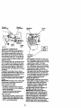
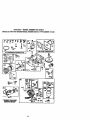
Owner's Manual
CRRFT$I4nH"
15.5 HP
ELECTRIC STAR_
42" MOWER
6 SPEED TRANSA_LE
LAWN TR. f TX3R
Model No.
917.270613
• Safety
• Assembly
• Operation
• Maintenance
• Repair Parts
_,--
.............. r'
CAUTION:
Read and follow all
Safety Rules and Instructions
before operating this equipment.
""
........
i II
r
For answers to your questions
about this product, Call:
1-800-659-5917
Sears Craftsman Help Une
5 am - 5 pro, Mon- Sat
Sears, Roebuck and Co., Hoffman Estates, IL 60179
W_
..................................
,,,.,..°,.*..°.2
Safety Rules...........................................2
Product
spec _..O.n
_s............................
5
Assembly..................:.............................8
Operation............................................. 11
MaintenanceSchedule.........................17
Maintenance......................................... 17
Service andAdjustments......................21
Storage.................................................27
Troubleshooting
....................................28
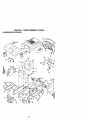
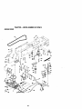
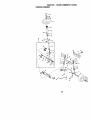
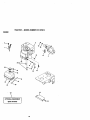
Repair Parts .........................................32
PartsOrdering.......................BeckCover
LIMITED TWO YEAR WARRANTY ON CRAFTSMAN RIDING EQUIPMENT
For two (2) yearsfrom the date of purchase,ifthis CraftsmanRidingEquipmentis maintained, lubricatedand tuned up accordingto the instructionsin the owner'smanual,
Sears willrepairor-rsplsce,free of charge, anyparts found to be defectivein materialor
worla'nanship.
This Warrantydoes not cover:.
• Expendableitemswhichbecomeworndudngnormaluse, such as blades, spark
plugs,air cleaners,belts,etc.
• Tiro replacementor repair causedby puncturesfrom outsideobjects,such as nails,
thorns,stumps,or glass.
• Repairs necessarybecauseof operatorabuse,negligence,improperstorage or accident or the failureto maintainthe equipmentaccordingto the instructionscontainedin
the owner's manual.
• Ridingequipmentused for commsrciaior rentalpurposes.
LIMITED 90 DAY WARRANTY ON BATTERY
For ninety(90) days from date of purchase,if any batteryincludedwiththis ridingequip
ment provesdefectivein materialor workmanshipand ourtestingdeterminesthe batterywill not holda charge, Sears willreplacethe batteryat no charge. In-homewarranty
serviceon yourCraftsmanridingequipment is availableat no chargefor 30 days from
the date of pumhese. Pleasecontactyour nearestservicecenter.After 30 daysfrom the
data of purchase,warrantyservice is availablebytakingyourCraftsmanridingequipmentto your nearestSears ServiceCenter. (In-homewarrantyservicewillstillbe available after 30 days from the date of purchasebut a standardtrip chargewill apply).This
warrantyappliesonlywhilethis productis in the UnitedStates.This Warrantygives you
specificlegalrights, and you may also have otherrightswhichmay varyfrom state to
state.
Sears, Roebuckand Co., D/817 WA, HoffmanEstates,IL 60179
GENERAL OPERATION
• Read, understand,and followail instructionsin the manuai and on the machine
beforestarting.
• Only allow responsibleadults,who are
familiarwiththe instructions,to operate
the machine.
• Clear the area of objectssuch as rocks,
toys, wire, etc., whichcould be picked
up and thrownby the blade.
• Be surethe area is clear of otherpeople
before.mowing"Stop machineif anyone
entersthe area.
2
• Never carry passengers.
• Do not mow in reverse unlessabsolutely necessary.Always lookdawn and
behindbeforeand whilebacking.
• Be aware of the mower dischargedirection and do not point it at anyone. Do
not operatethe mowerwithouteither
the entiregrasscatcher or the guard in
place.
• Slow dawn beforetuming.
• Never leave a running machine unattended.Alwaystum off blades,set parking brake,stop engine,and remove
keys beforedismounting.
• Do nottryto stabUizethe mach_e by
•Tum otf blades when not rnowing.
• Stop engine before removing grass
catcher or unclogging chute;
putting your foot on the ground.
• Do not ose grees catcher on 8tesp
slopes.
• Mowonly in deylight orgeed arlir_al
Ikjht.
CHILDREN
• Do not operate the machine while under
. the influence of alcohol or drugs.
• Watch for treffic when operating near or
crossing roadways.
• Use extra care when loading or unloading the machine into a trailer or truck.
Tragic accidents can occur if the operator
is not alert to the presence of children.
Children are oftefl a_
to the
machine and the mowing activity. Never
assume that children will remain where
you last saw them.
• Keep children out of the mowing area
and under the watchful care of another
responsible adult.
• Be alert and turn machine off if children
enter the area.
• Before and when backing, look behind
and down for small children.
• Never carry children. They may fall off
and be seriously injured or interfere with
safe machine operation.
• Never allow children to operate the
machine.
• Use extra care when approaching blind
comers, shrubs, trees, or other objects
that may obscure vision.
SLOPE OPERATION
Slopes are a major factor related to Ioasof-control and tipover accidents, which
can result in severe injury or death. All
slopes require extra caution. If you cannot
back up the slope or if you feel uneasy on
it, do not mow it.
DO:
• Mow up and down slopes, not across.
• Remove obstacles such as rocks, tree
limbs, etc.
• Watch for holes, ruts, or bumps. Uneven
terrain could overtum the machine. Taft
grass can hide obstacles.
• Use slow speed. Choose a low gear so
that you wifl not have to stop or shift
while on the slope.
• Follow the manufacturer's recommendations for wheel weights or counterweights to improve stability.
• Use extra care with grass catchers or
other attachments. These can change
the stability of the machine.
• Keep all movement on the slopes slow
and gradual. Do not make sudden
changes in speed or direction.
• Avoid.starting or stopping on a slope. If
tires inse traction, disengage the blades
and proceed slowly strsight.down the
slope.
DO NOT:
• Do nottum on slopes unless necessary,
and then, turn slowly and gradually
downhill, if possible.
• Do notmow near dropoffs, ditches, or
embankments. The mower could soddenly tum over if a wheel is over the
edge of a cliff or ditch, or if an edge
caves in.
• Do no
g__mowon wet grass. Reduced
traction could cause sliding.
SERVICE
• Use extra care In handling gasoline and
other fuels. They are flammable and
vapors are explosive.
Use only an approved container.
Never remove gas cap or add fuel
with the engine running. Allow engine to cool before refueling. Do not
smoke.
Never refuel the machine indoors.
Never store the machine or fuel
container inside where there is an
open flame, such as a water heater.
• Never run a machine inside a closed
area.
• Keep nuts and bolts, especially blade
attachment bolts, tight and keep equip
ment in good condition.
• Never tamper with safety devices.
Check their proper operation reguledy.
• Keep machine free of grass, leaveS, or
other debds build-up. Clean oil or fuel
spillage. Allow machine to cool before
stodng.
• Stop and inspect the equipment if you
strike an object. Repair, If necesssPJ,
before restarting.
3
• Never make adjustmentsor repairswith
the engine refining.
• Grass catchercomponentsam subject
to wear, damage, and deterioration,
whichcouldexpose movingparts or
allow objectsto be thrown. Frequently
check components and replacewith
reanufacturer's recommendedpads,
when necessary.
• Mower blades are sharp and can cut.
Wrap the blade(s) or wear gloves, and
use extra caution when servicing there.
• Check brake operation frequently.
Adjust and service as required.
• Be sure the area is clear of otherpeople
beforemowing. Stop machine if anyone
entemthe area.
• Never carrypassangem.
• Do not mowin reverseunlessabsolutely necessary.Always lookdown and
behindbeforeand while backing.
• Never carrychildren.They may fall off
and be seriouslyinjuredor interferewith
safe machineoperation.
• Keep children out of the mowingarea
and under the watchfulcare of another
respor,sib_eadutt.
• Be alert and turn machineoff if children
enter the area.
• Beforeand when becking, lookbehind
and downfor small children.
• Mow up and down slopes (15 ° Max), not
across.
• Remove obstacles such as rocks, tree
limbs, etc.
• Watch for holes, ruts, or bumps. Uneven
terrain could overturn the machine. Tall
graSs can hide obstacles.
• Use slow speed. Choose a low gear so
that you will not have to stop or shift
while on the slope.
• Avoid starting or stopping on a slope. If
tires lose traction, disengage the blades
and proceed slowly straight down the
slope.
• Do nottum on slopes unless necessary,
and then, tam slowly and gradually
downhi,, if poseible.
ALook for this symbolto pointout important safetyprecautions.It meansCAUTIONI!! BECOMEAWAREIII YOUR SAFETY IS iNVOLVED.
_,WARNING:
The engine exhaust from
this product contains chemicals known to
the State of Callfomia to cause cancer,
birth defects, or other reproductive harm.
_,CAUTION: In order to preventaccidentalstartingwhen setting up, transpo_ng,
adjustingor makingrepairs alwaysdisconnectspark plug wire and place wire where
it cannotcontaCtspark plug.
4
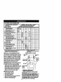
PRODUCT SPECIFICATIONS
GASOU_
CAPACITY
AND TYPE:
MAINTENANCE AGREEMENT
A Seara _
Agreementis available on this product.Cent=rotyournearest
Searestore for details.
1.25 GALLONS
UNLEADED
REGULAR
CUSTOMER
OIL'WPE
SAE30 (above32_F)
_,PI-SF/SG/SH): SAE5W-30
(below32"F)
OILCAPACITY:
3.0 PINTS
3PARKPLUG:
_AP:;030")
ChampionRC12YC
_/ALVE
3LEARANCE:
INTAKE: .003"-.057'
EXHAUST:.005"-.00"/"
3ROUND SPEED
VIPH):
FORWARD:
1ST
2ND
3RD
4TM
5TM
6TM
REVERSE:
• Read and observe the safety roles.
• Follow a regular schedule in maintaining, cadng for and using your tractor.
• Follow the instructions under "Malntanance" and "Storage" sections of this
owner's manual.
,_WARNING:
This tractor is equipped
with an internal combustion engine and
should not be used on or near any unimproved forest*covered, bnJsh-covered or
grass-covered land unless the engine's
exhaust system is equipped with a spark
arrester meeting applicable local or state
laws (if any). If a spark arrester is used, it
should be maintained in effective working
order by the operator.
In the state of California the above is
required by law (Section 4442 of the
California Public Resources Code). Other
states may have similar laws. Federal
laws apply on federal lands. A spark
arrester for the muffler is available through
your nearest Sears Authorized Service
Center (See REPAIR PARTS section of
this manual).
1.1
1.4
2.2
3.3
4.4
4.9
1.4
]'IRE PRESSURE: FRONT: 14 PSI
REAR: 12 PSI
3HARGING
SYSTEM:
3 AMPS BA'I-I'ERY
5 AMPS HEADLIGHTS
E3ATTERY:
AMP/HR:
25
MIN. CCA: 190
CASE SIZE: U1R
BLADE BOLT
TORQUE:
RESPONSIBILITIES
27-35 FT. LBS.
CONGRATULATIONS on your pumhase
of a Craftsman Tractor. It has been
designed, engineered and manufactured
to give you the best possible dependability
and performance.
Should you expedenceany problemyou
cannoteasilyremedy,please contactyour
nearest SearsAuthorizedSewloe Center.
We have competent, welt-trainedtechnicians and the propertoolsto service or
repairthis tractor.
Pleaseread and retainthis manual.The
instructions
willenable you to assemble
and maintainyourtractorproperly.Always
observethe =SAFETYRULES'.
5
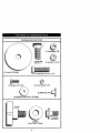
Parts Bag contentsshownfull size
®
(1) Lockwasher 3/8
@
(1) Hex Bolt
3/8o16 x 1
(1) Large Flat Washer
(2) Screws #10 x 5/8
(1) Locknut 5/16-18
_x
1-1/4
(2) Lock Washers #10
(2) Weld Nuts 010 I_
(2) Washers 3/16 x 3/4 x 16 Gauge
m
(1) Knob
i
i
©
(1) Shoulder
Bolt 5/16-18
(1) Washer
17/32x 1-3/16x 12 Gauge
Parts packed separately in carton
J
Seat
Muk:her
Video
Plate
Cassette
Steor;ng
Wheel
I
Manual
Steering
Boot
Parts Bag
Parts Bag contentsnotshown full size
Shaft
Steering
Wheel
Insert
12) Keys
Steodng
,
Siope Sheet
7
,
Wheel
Adapter
Yournowtractor
hasbeenassembled
atg_efactory
withexception
ofthosepadsleft
unassembled
forshipping
purposes.
Toensure
safeandproper
operation
ofyourtractor
allparts and hardware you assemble must be tightened securely. Use the correct tools
as necessary to insure proper tightness. Review the video cassette before you begin.
TOOLS REQUIRED FOR
ASSEMBLY
" A socketwrenchset will make assembly
easier.Standardwrenchsizes you need
are listedbelow.
(1) 9/16" wrench
(1) Utilityknife
(2) 1/2"wrench
(1) Pliers
(1) _re pressure gauge
(1) PhillipsScrew driver
When rightor lefthand is mentionedin
this manual,it means from yourpointof
view, whenyou are in the operatingposition (seatedbehindthe steeringwheel).
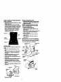
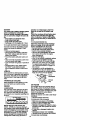
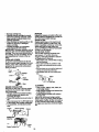
• Assemble large flat washer, 3/8 lock
washer, 3/8 hex belt and tighten securely.
• Snap steering wheel insert into center
of steering wheel.
• Remove protective materials from tractor hood and grill.
IMPORTANT: Check for and remove any
staples in skid that may puncture tires
where tractor is to roll off skid.
Insert
'_
F'_
3/8 Hal Bolt
_3/8
I.._asher
TO REMOVE TRACTOR FROM
CARTON
UNPACK CARTON
• Remove all accessible loose pads and
parts boxes from shipping carton (See
page 6).
• Cut, from top to bottom, along lines on
all four comers of shipping carton, and
lay panels flat.
• Check for any additional loose parts or
boxes and remove.
BEFORE ROLUNG TRACTOR OFF
SKID
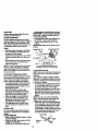
ATrACH STEERING WHEEL
ASSEMBLE EXTENSION SHAFT AND
BOOT
• Slide extension shaftontolowersteeringshaft.Alignmountingholesin extensionand lowershaftsand install5/16
hex boltand IncknuL_ghten securely.
IMPORTANT:Tightenboltand nut securely to 18-22 ft. Ibs.torque.
• Placetabs of steeringbootover tab
slotsin dash and pushdownto secure.
INSTALLSTEERING WHEEL
• Positionfront wheels of the tractorso
they are pointingstraight forward.
• Slidesteeringwheel adapterontosteeringshaftextension.
• Positionsteeringwheel socross bars
are horizontal(leftto dght)and slide
ir_e bootand ontoadapter.
Stee_teedng
Wheel
_t
Extension
Shaft
_JF
Adapter
"'"---,...,.,_
i_
5/16 Lonlm_ o__
/
LowerSteedng......_/
•
_, "%'_--.
•
t
Hex
_.
_
J
,
i
t
TO ROLL TRACTOR OFF SKID (See
Operation soctlon for location and
function of controls)
• Press lift lever plunger and raise attachment lift lover to its highest position.
• Release parking brake by depressing
clutch/brake pedal.
• Place gearshift lever in neutral (N) position.
• Roll tractor forward off skid.
• Remove banding holding discharge
guard up against tractor.
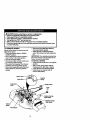
HOW TO SET UP YOUR TRACTOR
CHECK BATTERY
• Liftseat pan to raisedpos_dionand open
battely box door.
• It thisbatteryis put into se_ice after
monthand year indicatedon label (label
iocated between termi_ls) chargebattery for minimumof one hour at 6-10
amps. (See "BA'I-rERY=in MAINTENANCE sectionof this manual for
charginginstructions).
Seat Pan
Label
Battery
Be
INSTALL MULCHER PI.ATE
• instafltwo latch boolw to musher plata
using screw,washer,lock washer,and
weld nutas shown.
NOTE: pre-aasembleweld nutto latch
hookby insertingweld nut fromthe top
withhookpointingdown.
• Tightenhardwaresecurely.
• Raise and hold deflectorshield in uprightpos'_on.
• Placefrontof muicherplate over frontof
mowerdeck openi_Jand slideinto
place,as shown.
• Hookfrontlatch intohole on frontof
mowerdeck.
• Hookrear latch intoholeon backof
mowerdeck.
,_CAUTION: De not removedischarge
guardfrom mower.Raise and holdguard
when attachingmuicher plate and allow it
to reston platewhilein operation.
Weld Nut From
The Top
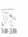
INSTALL SEAT
Adjust seat before tightening adjustment
knob.
• Remove cardboard packing on seat
pan,
• Place seat on seat pan and assemble
shoulder boll -Rghten shoulder bolt
securely.
• Assemble adjustment knob and flat
washer loosely. Do not tighten.
• Lower seat into operating position and
sit on seat.
• slide seat un_l a comfortable position is
reached which allows you to press
clutch/brake pedal all the way down.
• Get off seat without moving its adjusted
,position.
• R_,_e seat and tighten adjustment knob
securely.
- Seat
Seat Pan
Shoulder
Belt
Washer
Adjustment
Knob
Hoot( Points
_o'_
Lock
[_J
Weld Washer _
Nut'x_
"_
Screw _X_
tch
D\\ \weld.ut
Washer
M_cher
Plate
'_
Screw
Shield
Deflector
__
TO CONVERT TO BAGGING OR DISCHARGING
Simplyremovemulcherplate and store in
a safe place.Yourmower is now ready for
dischargingor installationof optional
grasscatcheraccessory.
NOTE: It is not necessaryto change
blades.The mulcherbladesare designed
for dischargingand baggingalso.
_HECK TIRE PRESSURE
The tires on yourtractorwere overinflated
at the factory for shippingpurposes.
Correcttire pressureis importantfor best
cu_ingperformance.
• Reducetire pressureto PSI shownin
=PRODUCTSPECIFICATIONS"on
page 5 of this manual.
CHECK DECK LEVELNESS
For bestcuttingresults,mower housing
shouldbe propedyleveled. See "TO
LEVEL MOWER HOUSING"in the
Service andAdjustmentssectionof this
manual.
CHECK FOR PROPER PosmoN OF
ALL BELTS
See the figuresthat are shownfor replacingmotionand mower blade ddve belts in
the Serviceand Adjustmentssectoinof
this manual. Verifythat the beltsare muted correctly.
CHECK BRAKE SYSTEM
After you learn howto operateyourtractor,checkto see that the brake is propedy
adjusted.See "TO ADJUST BRAKE"in
the Service and Adjustmentssectionof
this manual.
10
/ CHECKLIST
PLEASE REVIEW THE FOLLOWING
CHECKLIST:
/
All assembly instructions have been
completed.
/ No remaining loose pads in carton.
,/ Battery is properly prepared and
charged. (Minimum 1 hour at 6 amps).
,/ Seat is adjusted comfortably and
tightened securely.
•/" All tires are properly inflated. (For
shipping purposes, the tires were
ovednflated at the factory).
,/ Be sure mower desk is propedy leveled
side-to-side/front-to-rear for best
cutting results. ('Rres must be propedy
inflated for leveling).
4" Check mower and drive belts. Be sure
they are muted propedy around pulleys
and inside all belt keepers.
,/ Check widng. See that all connections
are still secure and wires are properly
clamped.
WHILE LEARNING HOW TO USE YOUR
TRACTOR, PAYEXTRAATTENTION TO
THE FOLLOWING IMPORTANTITEMS:
/ Engineoilis at properlevel.
,/ Fueltank is filled withfresh, clean,
regularunleadedgasoline.
,/ Becomefamiliarwithall controls- their
locationand function. Operate them
beforeyou start the engine.
4" Be surebrake systemis in safe
operatingcondition.
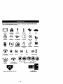
These symbolsmay appear on yourtractoror in literaturesuppliedwith the product.
Leam and understandtheir meaning.
&
BATTERY
CAUTION ON
WARNINQ
REVERSE
ENGINE ON
ENGINE OFF
OIL PRESSURE
LIGHTS ON
OVELRTEMP
FUEL
CHOKE
MOWER HEIGHT
PARKING BRAKE
LOCKED
UNLOCKED
r_'_ R N
ATTACHMENT
CLUTCH ENGAGED
REVERSE
NEUTRAL
ATTACHMENT
IGNmON
CLUTCH
FORWARD
FAST
H
L
HIGH
LOW
KEEP AREA CLEAR
SLOW
t
MOWER LIFT
pARKING BRAKE
SLOPE HAZARDS
(SEE SAFETY RULES SECTION)
DISENGAGED
FREEWHEEL
DANGER, KEEP HANDS AND FEET AWAY
11
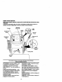
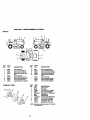
KNOW YOUR TRACTOR
R_D
THIS OWNER'S MANUALAND SAFETY RuLEs BEFORE OPERATING YOUR
TRACTOR
Compare the illustrations with your tractor to familiarize yourself with the locations of
various controls and adjustments. Save this manual for future reference.
Ammeter
Attachment
ClutchLever
ThrottleChoke
Control
Light
Ignition
Switch
LiftLever
Plunger
Attachment Uft
Clutch/Brake
Pedal
Height
Adjustment
Indicator
Brake
Gearshift
Lever
Our tractorsconformto the safetystandardsofthe American
NationalStandardsInstitute.
A'r'rA_3HMENT CLUTCH LEVER: Used
to engage the mower blades, or other
attachments mounted to your tractor.
LIGHT SWITCH: Tums the headlights on
and off.
THROTTLE/CHOKE
CONTROL: Used
GEARSHIFT LEVER: Selects the speed
and direction of tractor.
ATTACHMENT LIFT LEVER: Used to
raise, lower, and adjust the mower deck or
other attachments mounted to your tractor.
LIFT LEVER PLUNGER: Used to release
for starting and controlling engine speed.
CLUTCH/BRAKE PEDAL: Used for
attachment lift lever when changing its
position.
declutching and braking the tractor and
starting the engine.
PARKING BRAKE: Locks clutch/brake
ped_LJntothe brake position.
IGNITION SWITCH: Used for starting and
stopping the engine.
AMMETER: Indicates battery charging (+)
or discharging (-).
12
|
The operation of any tractor can result in foreige objects thrown into the |
eyes, which can result in severe eye damage. Always wear safety glasses or eye shields while operating your tractor or performing any adjustmanta or repairs. We recommend a wide vision safety mask over spectaclse, or standard safety glasses.
I
HOWTOUSEYOURTRACTOR
Yourtractor
isequipped
withan operator
• Never use choke to stop engine.
IMPORTANT: Leaving the ignition switch
in any position other than =OFF" will cause
the battery to be discharged, (dead).
NOTE: Under certain conditions when
tractor is standing idle with the engine running, hot engine exhaust gases may
cause =browning" of grass. To eliminate
this possibility, always stop engine when
stopping tractor on grass areas.
A CAUTION: Always stop tractor completely, as described above, before leaving
the operator's position; to empty grass
catcher, etc.
THROTrLE CONTROL
Always operate engine at full throttle.
• Operating engine at less than full throttle reduces the battery charging rate.
• Full throttle offers the best bagging and
mower performance.
TO MOVE FORWARD AND BACKWARD
The direction and speed of movement is
presence sensing switch. When engine
is running, any attempt by the operator to
leave the seat without first setting the
parking brake will shut off the engine.
TO SET PARKING BRAKE
i
=BRAKE"
position andpedal
hold. into full
epress clutch/brake
Place par.kingbrake lever in
ENGAGED position and release pressure from clutch/brake pedal. Pedal
should remain in "BRAKE" position.
Make sure parking brake will hold tractor secure.
Throttle/Choke
Controllever
AttachmentClutchLever
"Engaged"Position
"Disengaged"
Position
Clutc_rake
Pedal "Ddve"
Position
Brake
Position
Position
STOPPING
Position
Lever
MOWER BLADES• To stop mowerblades, moveattachmentclutchlover to "DISENGAGED"
position.
GROUND DRIVE •-To stopgrounddrive, depress
clutch/brakepedal intofull "BRAKE"
pusition.
• Move gearshift lever to neutral(N) position.
ENGINE • Move throttle control to slow position.
NOTE: Failure to move throttle control to
slow position and allowing engine to idle
before stopping may cause engine to
"back/ira'.
•Tum ignition key to "OFF" position and
r,,move key. Always remove key when
leaving tractor to prevent unauthodzed
use.
13
controlled by the gearshift lever.
Start tractor with clutch/brake pedal
depressed and gearshift lever in neutral
(N) position.
• Move gearshift lever to desired position.
• Slowly release clutch/brake pedal to
start movement.
IMPORTANT: Bdng tractor to a complete
stop before shifting or changing gears.
Failure to do so will shorten the useful life
of your transaxle
TO ADJUST MOWER CUTTING HEIGHT
The position of the attachment lilt lever
determines the cuffing height.
• Grasp lilt lever.
Press plunger with thumb and move
lever to desired position.
The cutting height range is approximately
1-1/2 to 4.'. The heights are measured
from the ground to the blade tip with the
engine not running. These heights are
approximate and may vary depending
upon soil conditions, height of grass and
types of grass being mowed.
• The average lawn should be cut to
approximately 2-1/2 inches dudng the
cool season and to over 3 Inches dudng
hot months. For healthier and better
looking lawns, mow often and after
moderate growth.
• Forbestcutting
performance,
grass
• Do not push or tow tractor at mere than
over6inchesInheightshould
be
five (5) MPH.
mewed
twice.Makethefirstcutrelative- NOTE: To protect hood from damage
ly high; the second to desired height.
TO OPERATE MOWER
Your tractor is equipped with an operator
t_msenca sensing switch. Any attempt by
e operator to leave the seat with the
engine running end the attachment clutch
- engaged will shut off the engine.
• Select desired height of cut.
• Start mower blades by engaging attachment clutch control.
• TO STOP MOWER BLADES - disengage attachment clutch control.
_.CAUTION:
Do not operate the mower
without either the entire grass catcher, on
mowers so equipped, or the discharge
guard in place.
AttachmentLiftLever
AttachmentLiftLever
Hig
High Position
Position
Low
Position
when transporting your tractor on a truck
or a trailer, be sure hood is closed and
secured to tractor. Use an appropriate
means of tying hood to tractor (rope, cord,
etc.).
BEFORE
STARTING
THE ENGINE
CHECK ENGINE OIL LEVEL
• The engine in your tractor has been
shipped, from the factory, already filled
with summer weight oil.
• Check engine oil with tractor on level
ground.
• Remove oil fill cap/dipstick and wipe
clean, reinsert the dipstick and screw
cap tight, wait for a few seconds,
remove and read oil level. If necessary,
add oil until "FULL" mark on dipstick is
reached. Do not overfill.
• For cold weather operation you should
change oil for easier starting (See =OIL
VISCOSITY CHART" in the Maintenance section of this manual).
• To change engine oil, see the Maintenance section in this manual.
ADD GASOLINE
• Fill fuel tank. Use fresh, clean, regular
unleaded gasoline with a minimum of
87 octane. (Use of leaded gasoline will
increase carbon and lead oxide
deposits and reduce valve life). Do not
mix oil with gasoline. Purchase fuel in
quantities that can be used within 30
days to assure fuel freshness.
IMPORTANT: When operating in temperatures below 32°F(0°C), use fresh, clean
winter grade gasoline to help insure good
cold weather starting.
/ Guard
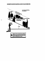
TO OPERATE ON HILLS
ACAUTION:
DO not drive up or down
hills with slopes greater than 15= and do
not drive across any slope. A slope guide
at the back of your manual is provided for
your use.
• Choose the slowest speed before starting up or down hills.
• Avoldstopping or changing speed on
hills.
AWARNING:
Experience indicates that
alcohol blended fuels (called gasohol or
using ethanol or methanol) can attract
moisture which leads to separation and
formation of acids dudng storage. Acidic
gas can damage the fuel system of an
engine while in storage. To avoid engine
problems, the fuel system should be emptied before storage of 30 days or longer.
Drain the gas tank, start the engine end
lot it run until _ fuel lines and carburetor
are empty. Use fresh fuel next season.
See Storage Instructions for additional
information. Never use engine or carburetor cleaner products in the fuel tank or
permanent damage may occur.
corltrol lever to slower position.
If stopping is absolutely necessary,
push
clutch/brake
pedal move
_uicklythrottle
to brake
If slowing
is necessary,
position end engage perking brake.
Move gearshift lever to I st gear. Be
sure you have allowed room for tractor
to ronslighgy as you restart movement.
parking
brake
end clutcfVbrake
pedal.
i To
restart
movement,
slowly release
Make all turns slowly.
TO TRANSPORT
• Raise attachment lift to highest position
with attachment lift control.
• When pushing or towing your tractor, be
surf"gearshift lever is in neutral (N)
position.
14
_,CAUTION:
Fig to bottom of gas tank
filler neck. Do not ovedgl. Wlpe off any
spilled oil or fuel. Do not store, spill or use
gasoline near an open flame.
TO START ENGINE
When starting the engine for the flint time
or if the engine has run out of fuel, it will
take extra cranking time to move fuel from
the tank to the engine.
-- Sit on seat in operating position,
depress clutch/brake pedal and set
perking brake.
• Place gear shift lever in neutral (N) position.
• Move attachment clutch to "DISENGAGED" position.
• Move throttle control to choke position.
NOTE: Before starting, read the warm
and cold starting procedures below.
• Insert key into ignition and tum key
clockwise to =START" position and
release key as soon as engine starts.
Do not run starter continuously for more
than fifteen seconds per minute. If the
engine does not start after several
attempts, move throttle control to fast
position, wait a few minutes and try
again. If engine still does not start,
move the throttle control back to the
choke position and retry.
WARM WEATHER STARTING (50 ° F and
above)
• When engine starts, move the throttle
control to the fast position.
• The attachments and ground drive can
now be used. If the engine does not
accept the load, restart the engine and
allow it to warm up for one minute using
the choke as described above.
COLD WEATHER STARTING ( 50° FAND
BELOW)
• When enginestarts,allow engineto run
with.th.e
Jhrottlecontrolin the choke
positionuntilthe engine runsroughly,
then movethrottle controlto fast position.This may requirean enginewarmup periodfrom severalsecondsto several minutes,dependingon thetemperature.
• The attachmentscan also be used duringthe enginewarm-upperiod.
NOTE: If at a highaltitude(above3000
feet) or in coldtemperatures(below32 F)
the carburetor fuel mixturemay need to be
adjustedfor best enginepedormance.
See "TO ADJUST CARBURETOR"In the
Se_and
Adjustmentssectionof this
manual.
NOTE: At a high elUtude(above3000
feet) or In coldtemperatures(below32 F)
the carburetor fuel mixturemay needto be
adjustedfor bestengine performance.
See "TO ADJUST CARBURETOR"in the
Service andAdjustmentssectionofthis
manual.
MOWING TIPS
• Tim chains cannot be used when the
mower housing is attached to tractor.
• Mower should be pmpedy leveled for
best mowing pedormance. See "TO
LEVEL MOWER HOUSING" in the
Service and Adjustments section of this
manual.
• The left hand side of mower should be
used for trimming.
• Drive so that clippings are discharged
onto the area that has been cut. Have
the cut area to the right of the machine.
This will result in a more even distribution of clippings and more uniform cutting.
• When mowing large areas, stad by turning to the right so that clippings will discharge away from shrubs, fences, driveways, etc. After one or two rounds,
mow in the opposite direction making
left hand turns until finished
• If grass is extremely tall, it should be
mowed twice to reduce load and possible fire hazard from dried clippings.
Make first cut relatively high; the second
to the desired height.
• Do not mow grass when it is wet. Wet
grass will plug mower and leave undesirable clumps. Allow grass to dry
before mowing.
• Always operate engine at full throttle
when mowing to assure better mowing
performance and proper discharge of
material. Regulate ground speed by selecting a low enough gear to give the
mower the best cutting pedormance as
well as the quality of cut desired.
• When operating attachments, select a
ground speed that will suit the terrain
and give best pedormance of the attachment being used.
15
MULCHING MOWING TIPS
IMI_DRTAI/T: Forhest perlormance,
keep mower housingfree of built-upgrass
and trash. Clean after each use.
• The specialmulchingbladewillrecut
the grassclippingsmany timesand
reducethem in size so that as they fall
ontothe lawn they willdisperseintothe
grass and not be noticed.Also, the
mulchedgrasswillbiodegradequickly
to providenutdantsfor the lawn.
Alwaysmulchwith yourhighestengine
(blade)speed as this willprovidethe
bestrecuttingactionof the blades.
• Avoidcuttingyourlawn when it is wet.
Wet grasstendsto form clumpsand
interfereswith the mulchingaction. The
besttimeto mowyourlawn is the early
afternoon.At this timethe grass has
driedand the newlycutarea willnot be
exposedto the directsun.
• Forbest results,adjustthe mowercuttingheightsothat the mower cutsoff
onlythe top one-thirdof the grass
blades. Forextremelyheavymulching,
reduceyourwidthof cut on each pass
and mow slowly.
• Certaintypasof gress and gressconditionsmay requirethatan area he
mulched a secondtime to completely
hidethe clippings. When doinga Sac"
ondcut, mowacrossor perpendicularto
the firstcut path.
• Change yourcuttingpatternfromweek
to week. Mow northto southone week
then change to east to westthe next
week. This willhelp preventmatting
and grainingof the lawn.
16
CUSTOMER RESPONSIBILITIES
FILL IN DATES
AS YOU COMPLETE
REGULAR
ATES
SERVICE
_o
P_,
iV'
Check Operat or PzeS(n_ _
T _ede_ _
R _
_orLee_ Fat=._==
V"
V'
I/
V',
It/
Sharpen/Replace Mower Blades
IIf4
T
_bri_
I/'
I/
O
Check Battely
_
I_
R
_
Lm/el
Clean Batter/and
Check Trar,.saxla
Terrnlnats
Cooling
Adjust Blade Belt(s)
Tension
Ad)u=t Motion
Drive Belt(s)
Check Engine
O11 Level
Change
E
ik_
Claan
Engine
(l_l
Tension
Ks
ti_
V _
Oil
V*t._
Air Filter
N Claan_r Screen
G
_1_
V*=
I/=
Inspect Muffier/_ark
Nrester
Rep4ace Oil Filter Of equipped)
I1_1.=
N CieenEnglne
Cooling
Fins
Replace
Spark Plug
Replace
Air Filter Paper
I,/=
I_
Cartridge
,
V*=
Replace
FuelRlter
GENERAL
LUBRICATION
RECOMMENDATIONS
The warranty on this tractor does not cover
items that have bonn subjected to operator
abuse or negligence. To receive full value
from the warranty, operator must maintain
tractor as instructed in this manual. Some
adjustments will need to be made pedodically to properly maintain your tractor.
All adjustments in the Service and
Adju_stmentssection of this manual should
be c'hecked at least once each season.
• Once a year you should replace the
spark plug, clean or replace air filter, and
check blades and belts for wear. A new
spark plug and clean air filter assure
proper air-fuai mixture and help your
engine run better and last longer.
BEFORE
EACH
Zerk
CHART
Zerk
• Front Wheel
Wheel
Beadng
Zerk
Beating Zerk
0 Atta_hrrm_t_
_tch
!
Pivot(s)
i
:
• SAE _0 or 10w30 MotorOIL
• General PurposeGrease
Referto M&_ntenance
"Engine"Secl_n
USE
•
•
•
•
Check engine oil level.
Check brake operation.
Check tire pressure.
Check operator presence and intedeck
.,s_'tems for proper operation.
• Check for loose fasteners.
17
IMPORTANT: Do not oil or grease the
pivot points which have special nylon bearings. Viscous lubricants will attract dust
and dirt that will shorten the r_feof the selflubricating bearings. If you feel they must
be lubricated, use only a d_, powdered
graphite type lubricant spanngly.
TRACTOR
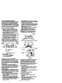
trailingedge up towardsdeck as shown.
IMPORTANT:To ensureproperassembly,
Always
obeerve
safelyruleswhenpercenter holeIn blade mustalignwith star
forming
anymaintenance.
on mandrel assembly.
BRAKE
OPERATION
• Reassemblehex belt, lockwasher and
Iftractor
requires
merethansix(6)feet
flat washerin exact order as shown.
stopping
distance
athighspeedinhighest • Tightenboltsecurely(27-35 Ft. Lbs.
gear,thenbrakemustbeadjusted.
(See
torque).
"TO ADJUST BRAKE" in the Service and
Adjustments section of this manual).
"TIRES
IMPORTANT:Bladeboltis Grade 8 heat
treated.
I EdgeUp
• Maintain proper air pressure in all tires
(See "PRODUCT SPECIFICATIONS"
on page 3 of this manual).
• Keep tires free of gasoline, oil, or insect
control chemicals which can harm rubber.
• Avoid stumps, stones, deep ruts, sharp
objects and other hazards that may
cause tire damage.
NOTE: To seal tire punctures and prevent
flat tires due to slow leaks, tire sealant
may be purchased from your local parts
dealer. Tire sealant also prevents tire dry
rot and corrosion.
MandrelAssembly
Blade
CenterHole;
Lock Washel
Star
/
Hex Bolt(Grade 8)*
*A Grade 8 heat treatedboltcan be
identifiedby six lineson the bolthead.
OPERATOR PRESENCE SYSTEM
Be sure that operator presence and interlock systems are working properly. If your
tractor does not function as descdbed
below, repair the problem immediately.
• The engine should not start unless the
clutch/brake pedal is fully depressed
and attachment clutch control is in the
disengaged position.
• When the engine is running, any
attempt by the operator to leave the
seat without first setting the perking
brake should shut off the engine.
• When the engine is running and the
attachment clutch is engaged, any
attempt by the operator to leave the
ee_;t should shut off the engine.
• The attachment clutch should never
operate unless the operat6r is in the
seat.
BLADE CARE
For bestresultsmowerbladesmusthe
kept sharp. Replace bentor damaged
blades.
BLADE REMOVAL
• Raise mowerto highestpositionto allow
access to blades.
• Remove hex bolt,lockwasher and fiat
w_r
securingblade.
• Installnow or resharpenedbladewith
18
TO SHARPEN BLADE
NOTE: We do not recommend sharpening
blade, but if you do, be sure the blade is
balanced.
Care should be taken to keep the blade
balanced. An unbalanced blade will cause
excessive vibration and eventual damage
to mower and engine.
• The blade can be sharpened with a file
or on a gdnding wheel. Do not attempt
to sharpen while it is on the mower.
• To check blade balance, you will need a
5/8" diameter steel belt, pin, or a cone
balancer. (When using a cons balancer,
follow the instructions supplied with balancer).
NOTE: Do not use a nail for balancing
blade. The lobes of the center hole may
appear to be centered, but are not.
• Slide blade onto an unthreaded portion
of the steel bolt or pin and hold the bolt
or pin parallel with the ground. If blade
is balanced, it should remain in a hodzontai position. If either end of the blade
moves downward, sharpen the heavy
end until the blade is balanced.
BATTERY
Yourtractor
has8 battery
charging
system
whichissufficient
fornormal
use.
However,
periodic
charging
ofthebattery
withanautomotive
charger
willextend
its
life.
• Keepbattery and terminals clean.
• Keep battery bolts tigM.
• Keep small vent holes open.
• Recharge at 6-10 amperes for I hour.
TO CLEAN BATTERY AND TERMINALS
Corrosion and dirt on the battery and terminale can cause the battery to "leak"
power.
• Remove terminal guard.
• Disconnect BLACK battery cable first
then RED battery cable and remove
battery from tractor.
• Rinse the battery with plain water and
dry.
• Clean terminals and battery cable ends
with wire brush until bdght.
• Coat terminals with grease or petroleum
jelly.
• Reinstall battery (See "REPLACING
BATTERY" in the SERVICE AND
ADJUSTMENTS section of this manual).
V-BELTS
Check V-belts for deterioration and wear
after 100 hours of operation and replace if
necessary. The belts are not adjustable.
Replace baits if they begin to slip from
wear.
TRANSAXLE COOLING
Keep transaxlefree from build-upofdirt
and chaffwhichcan restdctcooling.
ENGINE
LUBRICATION
Only use high quality detergent oil rated
with API service classirmation SF, SG or
SH. Select the oil's SAE viscosity grade
according to your expected operating temperature.
SAEVl,SCQ6_YGRN)ES
119&qE
RAI_REP.;_QE_*rrlOPAIF.DBEFORE
NE.x"r
OILCI.L'_GE
NOTE: Although multi-vlecosity oils
(5W30, 10W30 etc.) improve starling in
cold weather, these mulU-viscosify oils will
result in increased oil consumption when
used above 32°R Check your engine oil
level-hi'ore frequenUy to avoid possible
engine damage from running low on ell.
Change the oil after every 25 hours of
19
operatinnor at leeetonoee year Ifthe
trantoris not usedfor 25 hoursin one
year.
Check the crankcaseolt levelboforestartingthe engineend after eachelgM (8)
hoursof operation.Tightenoafilleap/dipsticksecurelyeach timeyou checkthe oil
level.
TO CHANGE ENGINE OIL
Determine temperature range expected
before oil change. All oil must meet API
service classification SF, SG or SH.
• Be sure tractor is on level surface.
• Oil will drain more freely when warm.
• Catch oil in a suitable container.
• Remove oil fill cap/dipstick. Be careful
not to allow dirt to enter the engine
when changing oil.
• Remove drain plug.
• After oil has drained completely, replace
oil drain plug and tighten securely.
• Refill engine with oil thmugh oil fill dipstick tube. Pour slowly. Do not overfill.
For approximate capacity see "PRODUCT SPECIFICATIONS" on page 5 of
this manual.
• Use gauge on oil fill cap/dipstick for
checking level. Be sure dipstick cap is
tightened securely for accurate reading.
Keep oil at "FULL" line on dipstick.
Oil RII
Cap/D]ps_.k
Oil Drain
Plug
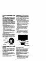
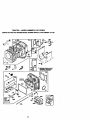
AIR FILTER
Your engine will not runpropedy using a
dirty airftlter. Clean the foam pre-cleaner
after every 25 hours of operation or every
season. Service paper cartridge every 100
hours of operation or every season,
whichever occurs first.
Service air cleaner more often under dusty
conditions.
• Remove knob(s) and cover.
TO SERVICE PRE-CLEANER
Wash It in liquid detergent and water.
Slide
foamif dry
pre-cleaner
offcloth.
cartridge.
Squeeze
in a clean
Saturate it in engine oil. Wrap it in clean,
absorbent cloth and squeeze to remove
excess oil.
• If very dirty or damaged, replace precleaner.
• Reinstall pre-cteaner over cartridge.
Reinstall cover and secure with knob(s).
TO SERVICE CARTRIDGE
• Remove
cartridge
MUFFLER
Inspect and replace corroded muffler and
spark armster (if equipped) as it could create a fire hazard and/or damage.
SPARK PLUGS
Replace spark plugs at the beginning of
each mowing season or after every 100
hours of operation, whichever occurs first.
Spark plug type and gap setting are
shown in "PRODUCT SPECIFICATIONS"
on page 5 of this manual.
IN-LINE FUEL FILTER
The fuel filter should be replaced once
each season. If fuel filter becomes
clogged, obstructing fuel flow to carburetor, replacement is required.
• With engine cool, remove filter and plug
fuel line sections.
• Place new fuel filter in position in fuel
line with arrow pointing towards carburetor.
• Be sure there are no fuel line leaks and
clamps are properly positioned.
• Immediately wipe up any spilled gasoline.
nut.
• Carefully remove cartridge to prevent
debds from entedng carburetor. Clean
base carefully to prevent dabds from
entedng carburetor.
• Clean cartridge by tapping gently on fiat
surface. If very dirty or damaged,
replace cartridge.
• Reinstall cartridge, nut, precleaner,
cover and secure with knob(s).
IMPORTANT: Petroleum solvents, such as
kerosene, are not to be used to clean the
cartddge. They may cause deterioratian of
the cartridge. Do not oil cartridge. Do not
use pressurized air to clean or dry car-
tddge.
CLEAN AIR SCREEN
Air screen must be kept free of dirt and
chaff to prevent engine damage from overheating. Clean with a wire brush or compressed air to remove dirt and stubbom
dried gum fibers.
Cover
Knob
Cartridge
Cartddge
CLEANING
• Clean engine,battery,seat, finish,etc.
of all foreignmatter.
• Keep finishedsurfacesand wheelsfree •
of all gasoline,oil, etc.
• Protectpaintedsurfaceswith automotivetype wax.
We do not recommendusinga garden
hoseto clean yourtractorunlessthe electricalsystem,muffler,air filterand carburetor are coveredto keepwater out.Water
in enginecan resultin a shortenedengine
life.
ENGINE COOUNG RNS
Remove any dust, dirt or oil from engine
cooling fins to prevent engine damage
from overheating.
• Remove screws from blower housing
and lift housing and dipstick tube
assembly off engine.
• Cover oil fill opening to prevent entry of
dirt.
• Use compressed air or stiff bristle brush
to thoroughly clean engine cooling fins.
• To reassemble, reverseabove procedure.
o_: T
Sc%
Blower
EngineCoolingRns '_
r_
Rug
2O
,SkCAUTION:Beforeperforminganyservice or adjustments:.
• Depressdutch/bmkspedal fullyand set peddng brake.
• Placegeamhiftlever in neutral(N) position.
• Place attachmentclutchin "DISENGAGED• position.
• Turn ignitionkey "OFF"and removekey.
• Make sure the blades and all movingpads have completelystopped.
• Disconnectspark plugwire from spark plugand placewire where it cannotcome
in contact withp_ug.
TO REMOVE MOWER
Mower willbe easier to removefrom the
rightside oftractor.
• Place attachmentclutchin "DISENGAGED" position.
• Move attachmentlift lever foeNard to
lowermowerto itslowestposition.
• Roll belt offengine pulley.
• Disconnectclutchrod from clutchlever
by removingretainerspring.
• Disconnectanti-swaybarfrom chassis
bracketby removingretainerspring.
• Disconnect susponsk:,narms from rear
deckbracketsby removingretainer
springs.
• Disconnect front links from deck by
removing retainer spdngs.
• Raise lift lever to raise suspension
arms. Slide mower out from under tractor.
IMPORTANT: If an attachment other than
the mower deck is to be mounted on the
tractor, remove the front links.
TO INSTALL MOWER
• Raise attachment lift lever to its highest
position.
• Slide mower under tractor with discharge guard to dght side of tractor.
• Lower lilt lever to its lowest position.
• Install mower in reverse order of
removal instructions.
Retainer
Front
Unk
(BothSides)
;pdngs
(Bo_ Sides)
Retainer
Spring
_vayt)ar
21
•
TOLEVEL
MOWER
HOUSING
Adjustthemower
wh.
iletractorisparked •
onlevelgrouno
oruriveway.
MaKe
sure
tiresarepmpedy
inflated
(See•PROD- •
UCTSPECIFICATIONS"
onpage5ofthis
manual).
Iftiresareoverorunaednflated,
youwillnotproperly
adjust
yourmower. •
SIDE-TO-SIDE
ADJUSTMENT
• Raise mower to its highest position.
•- Measure height frombottom of deck
cud to ground level at front comers of
mower. Distance "A" on both sides of
mower should be the same.
• If adjustment is necessary, make adjustment on one side of mower only.
• To raise one side of mower, lighten lift
link adjustment nut on that side.
• To lower one side of mower, loosen lift
link adjustment nut on that side.
NOTE: Each half turn of adjustment nut
will change mower height about 3/16".
• Recheck measurements after adjusting.
When distance "F" is 1/8" to 1/2" lower
at front than rear, tighten nut "H" against
trunnion on both front links.
To raise front of mower housing, loosen
nut "H" from trunnion on both front links.
31ghtan nut "G" on both front links an
equal number of tums.
When distance "F" is 1/8" to 1/2" lower
at front than rear, tighten nut =H"
against trunnion on both front links.
NOTE: Each full turn of nut =G" will
change dim. =F" by approximately 3/8".
• Recheck side-to-side adjustment.
Mandrel
%
.*
BothFrontLinksShouldbe Equalin Length
o,%=;
A---_X_-""
_
GroundLine
=o_.
Suspensi°n
_'""l_
Nut"G"
Trunnion
Frontlinks
FRONT-TO-BACK ADJUSTMENT
IMPORTANt': Deck must be revel side-teside. If the following front-to-back adjustment is necessary be sure to adjust both
front links equally so mower wi I stay evel
side-to-side;.
To obtain the best cuffing results, the
mower housing should be adjusted so the
front Is approximately 1/8" to 1/2' lower
then the rear when the mower is in its
highest position.
Check adjustment on right side of tractor.
Measure d_stance "F" directly in front of
and behind the mandrel at bottom edge of
mower housing as shown.
• Before making any necesaal_ adjust°
ments, check that both front links are
equal in length.
• If links are not equal in length, adjust
one link to same length as other link.
• To Iowffr front of mower housing, loosen
nut =G" on both front links an equal
number of turns.
TO REPLACE MOWER BLADE DRIVE
BELT (See IllustraUon Next Page)
The mowerblade drivebelt may be
replacedwithouttools. Parkthe tractoron
level surface.Engageparkingbrake.
BELTREMOVAL
• Remove mowerfromtractor(See "TO
REMOVE MOWER"in thissectionof
this manual).
• Work belt offbeth mandrelpulleySand
idlerpulleyS.
• Pullbelt away from mower.
BELTINSTALLATION
• Installnew belt in reverseorder of
removal.
• Make surebelt is in all pulleygrooves
and insideanbelt guides.
• Installmower in reverseorder of
removalinstructions.
22
Mandr_,Ptdley
IdlerPulleys
TO REPLACE MOTION DRIVE BELT
TOADJUST
BRAKE
Yourtractorisequipped
withanadjustablePark the tractor on level surface. Engage
brakesystem
whichismounted on the
parking brake. For assistance, there is a
right side of the transaxis.
If tractor requires more than six (6) feet
stopping distance at high speed in highest gear, then brake must be adjusted.
• Depress clutcWbrake pedal and engage
parking brake.
• Measure distance between brake operating arm and nut "A" on brake rod.
• If distance is other than 1-1/2", loosen
jam nut and tam nut "A" until distance
becomes 1-1/2". Retightan jam nut
against nut =A'.
• Road test tractor for proper stopping
distance as stated above. Readjust if
necessary. If stopping distance is still
greater than six (6) feet in highest gear,
further maintenance is necessary.
Contact your nearest authodzedservice center.
belt installation guide decal on bottom side
of left footrest.
• Remove mower (See "TO REMOVE
MOWER" in this section of this manual.)
• Remove belt from stationary idler and
clutching idler.
• Pull belt slack toward rear of tractor.
Remove belt upwards from transaxle
pulley by deflecting belt keepers.
• Pull belt toward front of tractor and
remove downwards from around engine
pulley.
• install new be_tby reversing above procedure.
Engine
Pulley
ClutchingIdler_
. Wi_ ParkingBrake'Engaged"
_
----
'
Nut "A"
StatioParytdter_
i
23
TO ADJUST STEERING WHEEL ALIGNMENT
If staedngwbeel creasbars are not horizontal (le]t to right)when wheels are peeitioned straight forward, remove steenng
wheel and reassemble per instrustions in
the Assembly section of this manual.
FRONT WHEEL TOE-IN/CAMBER
The front wheel toe-in and camber are not
ad ustable on your tractor. If damage has
occurred to affect the front whoa toe- n or
camber, contact your nearest authorized
service center.
TO REMOVE WHEEL FOR REPAIRS
&IMPORTANT: Your tractor Is equiped
with a 12 volt negative grounded system.
The other vehical must also be a 12 volt
negative grounded system. Do not use
your tractor battery to start other vshicals.
TO A'I-I'ACH JUMPER CABLES • Connect each end of the RED cable to
the POSITIVE (+) terminal of each battery, taking care not to short against
chassis.
• Connect one end of the BLACK cable to
the NEGATIVE (-) terminal of fully
charged battery.
• Connect the other end of the BLACK
cable to good CHASSIS GROUND,
away from fuel tank and battery.
* Block up axle securely.
Remove axle cover, retaining ring and
washers to allow wheel removal (rear
wheel contains a square key - Do not
lose).
• Repair tire ano reassemble.
• On rear wheels only: align grooves in
rear wheel hub and axle. Insert square
key.
• Replace washers and snap retaining
ring securely in axle groove.
• Replace axle cover.
NOTE: To seal tire punctures and prevent
flat tires due to slow teaks, tire sealant
may bepurchased from your local parts
dealer. _re sealant also prevents lire dry
rot and corrosion.
RetainiWn_h_
TO REMOVE CABLES, REVERSE
ORDER • BLACK cable first from chassis and
then from the fully charged battery.
• RED cable last from both batteries.
PositiveTerminal
NegativeTerminal
A
Battery
PositiveTerminal
(Rear Wheel Only)
NegativeTerminal
TO START ENGINE
WITH A WEAK
BATTERY
&CAUTION:
Lead-acid batteries gonerate explosive gases. Keep sparks, flame
and smoking matadals away from batterlss. Always wear eye protection when
around batteries.
If your battery is too weak to start the
engine, it should be recharged. (See
"BATTERY" in the MAINTENANCE section of this manual).
If "jumper cables" are used for emergency
starting, follow this procedure:
REPLACING BA'n'ERY
&CAUTION:
Do not short battery terminals by allowing a wrench or any other
object to contact both terminals at the
same time. Before connecting battery,
remove metal bracelets, wristwatch
bands,rings,etc.
Poaltive terminal must be connected first
to prevent epaddng from accidental
grounding.
• Lift seat pan to raised position and open
battery box door.
• Disconnect BLACK battery cable first
then RED battery cable and carefully
remove battery from tractor.
24
• Inatailnew hettery withterminaisin
seine positionas old battery.
• FirstconnectRED batterycable to positive (+) terminalwith hex boltand keps
nut as shown."nghtansecurely.
• ConnectBLACKgroundingcable to
negative(-) terminalwith remaininghe:<
belt and kepsnut."13ghtan
securely.
• Close batterybox door.
TO REMOVE HOOD AND GRILL
ASSEMBLY
• Raise hood.
• Unsnapheadlightwire connector.
• Standin frontof tmutor. Grasp hoodat
sides,tilt towardengineand liftoffof
tmctor.
• To replace,reverseabove procedures.
Headlight
r
Hex Bolt
Positive (Red) Cable
Negative (Black) Cable
TO REPLACE HEADLIGHT BULB
• Raise hood.
• Pull bulb holder out of the hole in the
backside of the grill.
• Replace bulb in holder and push bulb
holder securely back into the hole in the
backside of the gdll.
• Close hood.
INTERLOCKS AND RELAYS
Loose or damaged widng may cause your
tractor to run poorly, stop running, or prevent it from starting.
• _Checkwiring. See electrical wldng diagram in the Repair Parts section of this
manual.
TO REPLACE FUSE
Replace with 30 amp automotive-type
plug-in fuse. The fuse holder is located
behind the dash.
ENGINE
Maintenance, repair, or replacement of the
emission control devicse and systems,
which are being done at the customers
expense, may be performed by any nonroad engine repair ostablishement or individual. Warranty repairs must be performed by an authorized engine manufacturer's service outleL
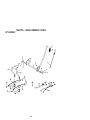
TO ADJUST THROTTLE CONTROL
CABLE
The throttle control has been preset at the
factory and adjustment should not be necessary. Check adjustment as deecdbed
below before loosening cable. If adjustment is necessary, proceed as follows:
• With engine not running, move throttle
control lever from slow to choke position. Slowly move lever from choke to
fast position.
• Check that holes "A• in govemor control
lever and hole in governor plate line-up.
If holes "A"am not aligned, loosen
clamp screw and move throttle cable
until holes are aligned. Tighten clamp
screw
25
S(_'U roly,
Governor
CorrbolLever
Qovernor
ControlPlate
Clamp
Screw
Holes"A"
Idle
Speed
Screw
Throltle
Lever
Throttle
Cable
TO ADJUST CARBURETOR
NOTE: The carburetor on this engine is
low emission. It is equipped with an idle
fuel adjusting needle with a lirniter cap,
which allows some adjustment within the
limits allowed by the cap. Do not attempt
to remove the limiter cap. The limitar cap
cannot be removed without breaking the
adjusting needle.
The carburetor has been preset at the factory and adjustment should not be necessary. However, minor adjustment may be
required to compensate for differences in
fuel, temperature, altitude or load. If the
carburetor does need adjustment, proceed
as follows:
In general, taming idle mixture valve In
(clockwise) decreases the supply of fuel to
the engine giving a leaner fuel/air mixture.
Turning the idle mixture valve out
(counterclockwise) increases the supply of
fuel to the engine giving a dcher fuel/air
mixture.
IMPORTANT: Damage to the needle valve
and the seat in carburetor may result if
screw is-turned in too tight.
PRELIMINARY SETTING
• Air cleaner assembly must be assembled to the carburetor when maldng carburetor adjustments.
• Be sure the throttle control cable is
acljusted properly (see above).
:INAL SETTING
• Start engine and allow to warm for five
minutes. Make final adjustments with
engine running and shift/motion control
lever in neutral (N) position.
26
Um_r
• Move throttle control lever to slow position. With finger, rotate and hold throttle
lever against idle speed screw. Turn idle
speed screw to attain 1750 RPM.
• Move throttle control lever to slow position. With finger, rotate and hold throttle
lever against idle speed screw. Turn idle
speed screw to attain 1750 RPM.
• While still holding throttle lever against
idle speed screw, rum idle mixture valve
full travel clockwise then counterclockwise until engine runs rough. Turn valve
to a point midway between those two
positions. Release throttle lever.
ACCELERATION TEST
• Move throttle control lever from slow to
fast position. If engine hesitates or dies,
tum idle mixture valve out (counterclockwise) 1/8 tum. Repeat test and
continue to adjust, if necessary, until
engine accelerates smoothly.
High speed stop is factory adjusted. Do
not adjust--damage may result.
IMPORTANT:. Never tamper with the
engine govemor, which is factory set for
proper engine speed, overapeeding the
engine above the factory high speed setting can be dangerous, if you think the
engine-govemed high speed needs
adjusting, contact your nearest authorized
service center, which has proper equipment to make any necessary adjustments.
Immed_tehj preparey_ tractorfor storage at the end of the season or ifthe tractor willnot be usedfor 30 days or more.
ACAUTION: Never storethe tractorwith
_hasolinein the tank insidea building
ere fumesmay reachan openflame or
spark.Allowthe engineto coolbefore
storingin any enclosure.
TRACTOR
Remove mowerfrom tractorfor winter
storage.This willallowyou to clean if thoroughly.Remove all dirt,grease, leaves,
etc. Store in a clean, dry area.
• Clean entiretractor(See "CLEANING"
in the Maintenancesection of this man-
FUEL SYSTEM
IMPORTANT: It is importantto prevent
gum depositsfromformingin essential
fuel systemports suchas carburetor, fuel
filler,fuel hose, or tank duringstorage.
Also, experienceindicatesthat alcohol
blendedfuels(calledgacoholor using
ethanolor methanol)can attract moisture
whichleadsto separationand formation of
acidsduringstorage.Acidicgas can damage the fuel systemof an enginewhilein
storage.
Drainthe fuel tank.
Start the engineand let if rununtilthe
_fuel lines and carburetor are empty.
Ual).
Never use engineor carburetorcleaner
• Inspectand replacebelts,if necessary
productsin the fueltank or permanent
(See belt replacementinstructionsin the
damage may occur.
• Use freshfuel nextseason.
Service andAdjustmentssectionofthis
manual).
NOTE: Fuelstabi_zeris an acceptable
• Lubricateas shownin the Maintenance
alternative in minimizingthe formationof
sectionof this manual.
fuel gum depositsdudngstorage.Add sta• Be sure that all nuts,boltsand screws
bilizerto gasolinein fuel tank or storage
are securelyfastened.Inspectmoving
container.A_aye fol|ow the mix ratio
parts for damage, breakageand wear.
foundon stabilizercontainer.Run engine
Replace if necessary.
at least 10 minutesafter addingstabllizer
• Touchup all rustedor chipped.paintsur- to allowthe stabilizerto reachthe carburefaces; sand lightlybeforepainting.
tor. Do not drainthe _as tank and carburetor if usingfuel stabihzer.
BATTERY
ENGINE OIL
* Fullychargethe batteryfor storage.
After a periodof time in storage,battery
Drain oil (withenginewa=rrn
_ and replace
with clean engineell. (See ENGINE" in
may requirerecharging.
the Maintenancesectionofthis manual).
• To help preventcorros=onand power
leakage duringlong periodsof storage,
CYLINDER(S)
battery cables shouldbe disconnected
Removespark plug(s).
and battery elsened thoroughly (see
Pourone ounceof oilthroughspark
"TO CLEAN BATTERYAND TERMIplug hole(s)intocylinder(s).
NALS"in the Maintenancesectionof
•Tum ignitionkey to =START"position for
this manual).
a few seconds to distributeoil.
• Aftercleaning, leave c_bles disconnect* • Replacewith new sparkplug(s).
ed and place cableswhere they cannot
OTHER
come:in-contactwith batteryterminals.
• If batteryis removedfrom tractorfor
• Do not store gasolinefrom one season
storage,do not store battepjdirectly on
to another.
concreteor damp surfaces.
• Replaceyour gasolinecan if it startsto
rust.Rustand/ordirtin your gasoline
willcause problems.
• II possible, store yourtractorindoors
and cover itto giveprotectionfrom dust
and dirL
• Coveryour tractorwith a suitableprotac_ve coverthat does not retainmdislure. Do not use plastic.Plasticcannot
breathe,which allowscondensationto
form and cause yourtractorto rust.
IMPORTANT: Never covertractorwhile
engineand exhaustareas are stillwarm.
27
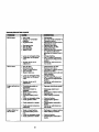
TROUBLESHOOTING
CHART
PROBLEM
CAUSE •
CORRECTION
Will not start
• Out of fuel.
• Engine not "CHOKED"
repel.
• _ngine
flooded.
Dirtyair filter.
i Dirtyfuel
Bad sparkplug.
filter,
Water in fuel.
• Loose or damaged widng.
Carburetor out of adjustment.
• Enginevalvesout of
adjustment.
Hard to stad
• Dirty air filter.
Bad spark plug.
• Weak or dead battery.
• Dirty fuel filter.
Stale or didy fuel.
• Loose or damaged widng.
Carburetor out of adjustment,
• Enginevalvesout of
adjustment.
Engine will not turn
over
• ClutcWbmke pedal not
depressed.
• Attachment clutch is
engaged.
• Weak or dead battery.
• Blown fuse.
• Corroded battery terminals,
Loose or damaged widng.
Faulty ignition switch,
• Faulty solenoid or starter.
• Faulty operator presence
switch(ea).
Engine clicks but
will not start
• Fillfuel tank.
• Sea "TO START ENGINE"in
Operationsection.
• Walt several minutes before
attemptingto start.
• Replace sparkplug.
Clean/re )laceair filter.
: Replace
Drain fuelfuelfilter.
tank and carburetor,refilltank with fresh
gasolineand replacefuel filtar.
• Check all widng.
See "ToAdjustCarburetor"
in Serviceand Adjustments
section.
• Contactan authorizedservice center.
• Clean/replace air filter.
Recharge or replace battery.
-..Replace
sparkfilter.
plug.
Replace fuel
Drain fuel tank and refill with
fresh gasoline.
• Check all widng.
See "ToAdjust Carburetor"
in Service and Adjustments
section.
• Contact an authorized service center.
• Depreseclutch/brakepedal.
• Disengage attachment
clutch.
Replace
Rechargefuse.
or replace battery,
Clean battery terminals.
: Check all wiring.
ChecPJreplace ignltion
switch.
• Chack/replace solenoid or
starter
• Contact an authodzed ser
vice center.
• Weak or dead battery.
• Corroded battery terminals.
• Rechargeor replacebattery.
• Clean batteryterminals.
" Loose or damaged widng.
Faulty solenoid or starter.
• Check all wiring.
Check/replace solenoid or
starter.
28
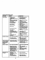
TROUBLESHOOTING
CHART
PROBLEM
CAUSE
CORRECTION
Lossof power
• Cuffingtoo much
grassJtoofast.
Throttlein "CHOKE"poaitioo.
• Build-upof grass,leaves
and trash undermower.
• Set in "HigherCut"pceition/reducespeed.
• Adjustthrottlecontrol.
: Dirtyair filter.
Low oillevel/dirtyoil.
• Faultysparkplug.
• Dirtyfuel filter.
• Stale or dirtyfuel.
• Water in fuel.
• Spark plugwire loose.
• Dirtyen,_gine
air
screer,mns.
• Dirty/cloggedmuffler.
Looseor damagedwiring.
Carburetoroutof adjustment.
• Enginevalvesout of
adjustment.
Excessive vibration
• Wom, bent or looseblade.
• Bent blade mandrel.
• Loose/damagedpart(s).
• Clean undersideof mower
housing.
Check odlevel/change
i Clesn/m..place
air filter.oil.
Cleanand regapor change
sparkplug.
; Replacefuel
filter. refillwith
Drainfuel tankand
freshgasoline.
• Drainfuel tank and carburetor,refilltank withfreshgasolineand replacefuel filter.
• Connectand tightenspark
plugwire.
• Clean engineair screen/fins.
all wiring.
i Check
Clean/replace
muffler.
See "To Adjust Carburetor" in
Service and Adjustments
section.
• Contact an authorized service center.
• Replaceblade. _ghten blade
boll
• Replaceblade mandrel.
• "13ghten
loosepart(s).
Replacedamagedpads.
Enginecontinuesto • Faultyoparator-safety
runwhen operator
presencecontrolsystem.
leavesseat with at
tachrnantclutch
engaged
• Checkwidng,switchesand
connections.If not
corrected, contactan authorizedservicecenter.
Poorcut - uneven
• ReplaceI_lade."Rghtanblade
bolt.
• Level mowerdeck.
• Cleanundersideof mower
housing.
• Replaceblade rnandrel.
Cleanaroundmandrelsto
openvent holes.
• Worn, bent or looseblade.
• Mowerdeck not level.
• Buildupof grass,leaves,
and trash undermower.
• Bent blademandrel.
• Clogged mowerdeckvent
holesfrom buildupof
grass, leaves,and trash
aroundmandrels.
Mowerbladeswill
not rotate
I. Obstructionin clutch
! • mechanism.
Worn/damagedmower
drivebell
• Frozanidlerpulley.
• Frozenblade mandrel.
29
• Remove obstruction.
• Replace mower drive belt.
• Replace idler pulley.
Replace blade mandrel.
TROUBLESHOOTING CHART
PROBLEM
CAUSE
CORRECTION
Poorgrass discharge
• Enginespeed too slow.
• Placethrottlecontrolin
"FAST"position.
* Shift to slowerspeed.
Allew,grass to dry before
mowmg.
• Level mowerdeck.
• Check tiresfor properair
res_3ure.
_ace/sharpen
blade.
Tightenblade bolt.
Clean undersideof mower
housing,
• Replacemower ddve belt.
Reinstallbladessharpedge
down.
• Replacewith bladeslistedin
this manual.
• Clean around mandrelsto
openvent holes.
• Travelspeed too fest.
• Wet grass.
* Mower deck not level.
• Low/uneven tire air pressure.
•Wom, bent or loose blade.
• Buildup of grass, leaves
and trash under mower.
• Mower drive belt worn.
• Blades improperly
installed.
• Improper blades used.
• Cloggedmowerdeckvent
holesfrom buildupof
grass,leaves, and trash
aroundmandrels.
Headlight(s) not
woddng (if so
equipped)
• Switch is "OFF'.
• 3ulb(s) burned out.
• :auity light switch.
• .oose or damaged widng.
• Blown fuse.
Battery will not
charge
Bad battery cell(s).
,* Poor cable connections.
_ equippeo).
Fau.lty regulator (if so
Faulty altemator.
Engine "backfires"
when tuming
engine "OFF"
* Engine throttle control not
set at "SLOW"
position for 30 seconds
before stopping engine,
30
* Tum switch "ON'.
* Replace bulb(s).
_ Check/replace light switch.
Check widng and connections.
• Replace fuse.
Replace battery.
Check/clean all connections.
i• Replace regulator.
• Replace alternator.
• Move throttle control to
"SLOW" position and allow
to idle for 30 seconds before
stopping engine.
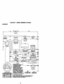
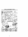
TRACTOR
- - MODEL NUMBER 917.270613
SCHEMATIC
BATTERY
AMMETER
(OPTIONAL)
RED
r_< )G
LI
IGNITIONswrrcH
YOUR TRACTOR IS
EQUIPPED WITH A SPECIAL
ALTERNATOR SYSTEM.
THE UGHTS ARE NOT
CONNEC'I1ED TO THE
BATTERY, BUT HAVE THEIR
OWN ELECTRICAL SOURCE.
BECAUSE OF THIS, THE
BRIGHTNESS OF THE LIGHTS
WILL CHANGE WITH ENGINE
SPEED. AT IDLE THE UGHTS
WILL DIM. AS THE ENGINE IS
SPEEDED UP, THE UGHTS
HEADLIGHTS
_
NON-REMOVABLE
CONNECTIONS
0
REMOVABLE
CONNECTIONS
WIRING INSULATED CLIPS
NOTE: IF WIRING INSULATED CLIPS WERE REMOVED FOR
WILL BECOME
BRIGHTEST.
SERVICING
OF THEIR
UNIT, THEY
SHOULD BE REPLACED TO
PROPERLY SECURE YOUR WIRING.
31
/-}
TRACTOR
--
MODEL NUMBER 917.270613
ELECTRICAL
21
25
pr
+l
32
.
TRACTOR - - MODEL NUMBER 917.270613
ELECTRICAL
KEY
NO.
1
2
8
16
19
20
21
22
24
25
26
27
28
29
3O
31
32
33
4O
41
42
43
44
45
52
70
NOTE:
PART
NO.
DESCRIPTION
144925
74760412
Bakery 12 VOLT 25 AMP
Boll Hex Hd 1/4-20unc x 3/4
156417
153664
STD551125
73350400
Case BatteP/
Switch, Intedock Push-kl
Washer Lock 1/4
Nut Jam Hex 1/4-20 uric
147430
4152J
4799,1
146147
108824X
73510400
4207J
Harness Asm Ught W/4152j
Bulb Light #1156
Cable Banefy 6 Ga 11" red
Cable Battery 6 Ga w/16 wire red
Fuse 30 AMP Auto Green
Nut Keps Hex 1/4-20 Unc
Cable Ground 6 Ga 12" black
121305X
140301
124211X
141226
109310X
156442
71110408
131563
145673
Switch Plunger Nc Gray
Switch Ign 4 Pos
Nut IgnNon
Cover Sw Key BJk 1 25 Text SLT
Key Ign Molded Craftsman
Harness Ign Man CI Am Hm 97
Bolt B_ Fm Hex 1/4-20 Unc x 1/2
Cover Tem,Jnal Red
Solenoid
73640400
121433X
141940
140422
Nut Keps Blk Hex 1/4-20 Uric
Ammeter Rec_ngular 6 Amp
Protection Wire Loop
Harness Er_e
B&S 14 OHV
AI compone__rne_,_s
1 Inch= 25.4 mm
33
give in U.S.
TRACTOR-- MODELNUMBER917.270613
CHASSIS
ANDENCLOSURES
28
12
55
14
11
115_
34
TRACTOR " - MODEL NUMBER 917.270613
CHASSIS AND ENCLOSURES
KEY
PART
NO.
NO.
DESCRIPTION
I
2
160393
140356
Chassis h._emUy
Drawt_"
3
4
5
6
17490612
STD551025
155272
155924X012
Screw. 131d, Roll 3/8-16 x 3/4
Washer" 13/32 x 3/4 x 16 Gauge
Bumper Hood/De._
Saddle
8
9
10
11
12
13
14
15
16
155138
161935X013
STD533710
155927
145660
135354X010
17490608
74180512
STD541431
Clip Retairmr SlJde-Oo
Dash
Bolt, Carriage 3/8-16 x 3/4
Panel, Dash, LH.
Clip "nnnerman Grille PA.
Panel, Asm. SLKSCR Dash R.H.
Screw Thdrol 3/8-16 x 1/2
Screw. Machine, Truss Hea_ 5/16-18 UNC x 3/4
Nut
17
18
24
144983)(558
126938X
STD523710
Hood Assembly
Bumper Hood
Bolt
25
26
28
29
30
19131312
STD541437
145135X558
155217X599
157584X535
Washer 13132 x 13/16 x 12 Gauge
Nut
Grille wiClip_; MS-558
Lens, Gdlle
Fender
31
33
34
35
37
38
39
51
52
53
54
55
57
140
145
136619
145244X558
145243X558
STD533707
1749(_
139886
139887
73800400
19091416
145201
161464
14520_
STD522507
158419
156524
Bracket, Fender Support
Footrest, Lit.
Footrest, I_H.
Bo_t
Screw Tl_lrol 5/16-18 x 1/2 TYT
Pivut Bracket Assemb_, LH.
Pi_Ot Bracket Assembly, R.H.
Nut Lock w/lnsert 114-20 UNC
Washm" 9/32 x 7/8 x 16 Ge.
Bracket Gdle Pfcko_ LH
Scow Hex WSHD 8-18 x 7/8
Bracket Gdlle Picboff P_H
Bolt, Fin Hex 1/4-20 UNC x .75
Brackst Flont Su_
Rod Pi_ot C_
s479J
Plug, Button
-
-
NO'rF_:
AI _
drnenslo_ give in U.S.
1 klCh= 25.4 mm
35
TRACTOR
- - MODELNUMBER917.270613
GROUND
DRIVE
36
TRACTOR - - MODEL NUMBER 917.270613
GROUND DRIVE
KEY
NO.
PART
NO.
....
2
3
4
5
6
7
8
10
11
12
13
14
18
19
21
22
24
25
26
27
28
29
3O
31
32
34
35
36
37
38
39
4O
41
42
47
DESCRIPTION
KEY
NO.
PART
NO.
DESCRIPTION
146682
123666X
12000028
121520X
17490512
162240
131679
$10561210
Transaxle (See Breakdown)
Peedess Model 206-508B
Sp_
Retain Brake T/a 2]nc
Pultay T_
18/20" tires
Ring Retainer # 5106-62
Strap Torque 3O Dngrees
Screw "n_lrol 5/16-18 x 3/4 TYT
Bracket Saddle Shift Tia
Rod Shf Sdl Ly/YT Str BIk Zinc
Pin Coner 1/8 x I Cad
48
49
50
51
52
53
54
55
56
57
154407
123205X
STD523715
$1I)541437
STD541431
105710X
2751R
105709X
STD523712
130801
Belk:mnk Clut.ch Grn Dry Stl
Retaber BOlt Slyle Sp_
Bolt Hex Hd 3_-16un¢ x 1.1/2
Nut Crownlock 3/8-16 UNC
Nut Crown Lock 5/16-18
Link Clutch 7 66
Clip fuel Line 13/32 M_g. Hole
Spdng Return Clutch 6 75
Bolt Rn Hex 3/8-16 unc x 1-1/4
V-Belt Gd Ddve
10o"701X
19151216
74550412
STD551125
STD523710
STD541437
Washer Plata Shf 388 Sq Hole
Washer 15/32 x 5/4 x 169a
Bolt 1/4-28unf Gr8 W/Patch
Washer Lock f'Iw Helical 1/4
Bolt Fin Hex
NUt Lock Hex W/Ins. 3/6-16 Uric
58
59
61
62
63
64
127274X
140312
17490612
8883R
140186
71170764
Keeper BO_ RH LT Pntizinc 169
Keeper Belt Cetltempan
Screw Thdrd 3/6-16 x 3/4 Ty-tt
Cover Pedal Btk Round
Pulley Eng CI Mech 38° LT/YT
Bolt Hex 7116-3O x 4 Gr 5
1Q6933X
130804
STD541237
Knob Rd 1/2-13 PtstcThds BIk
Rod _.e
BIk Zinc 26 840
NUt Hex Jam 3i8-16 Unc
65
66
70
STD551143
154778
134683
Washe¢ Lock Hvy Hid Spr 7/16
Keeper Belt Engine
Guide Belt Mowe¢ Ddve RH
106888X
STD551037
ST0561210
Spring Rod Brake 2 00 Zinc
Washer 13/32 x 13/16 x 16 Ga
PinCottarli8x5/4Cad
72
74
75
19132012
137057
121749X
Washer 13/32 x 1.1/4 x 12 Ga
SpacerAxta
Washer25/32.x1
l/4x16Ga
145204
12423OX
130807
127275X
STD523107
155071
120183X
STD551062
$1_571810
Rod Brake Parking Lt/Yt
C_o Brake P_ddng Red
Bracket M_ Transaxle
Keeper Salt LH LT 14 Ga
Bolt Flex lid 5/16-18unc x 5/4
Shaft Asm Pedal Foot
Beadng Nylon BIk 629 Id
Washer 21/32 x 1 x 16 Ga
Pin _
3/16 x 1"
76
77
78
79
96
112
113
116
145
S'1D581075
123583X
121748X
_8M
4497H
19091210
127285)(
72110610
74490540
F-dng #5133-75
Key Square 2 O x 1845/1865
Washer 25/32 x 1-5/8 x 169a
Key WoodnJff #9 3/16 x 3,'4
Retainer Spring 1"
Washer 9/32 x 5/4 x 10 Ga
Strap Torque LH LT
Bolt Rdhd Sq Neck 3/6-16 x 1.25
Bnd Hex FLGHD 5/16-18Gr.5
123674X
STD523727
4470J
154777
Pulley Idler Ftat
Bo;t Rn Hex 3i6-1f_unc x 2-3/4
Spacer Split 395 x 59 Bzp
Keeper Belt Idtar
148
149
150
151
159103
122G52X
150935
19133210
Spacer
Spacer Retainer pM Mower
Bushing Nylon Collernd
Washer 13i32 x2 x 10 Ga
19131312
127783
Washer 13/3€) x 13/16 x 12 Ga
Pulley Idler V Groove Ptast_
NOTE:
37
AUcomponent dimensions give in U.S
inches I inch =25.4 mm
TRACTOR-- MODELNUMBER917.270613
STEERING
ASSEMBLY
c-----e.°.,-°°.
• -.
i
,
J
.-/
~.~....°-
L
TRACTOR - - MODEL NUMBER 917.270613
STEERING ASSEMBLY
KEY
NO.
1
2
3
4
5
6
7
PART
NO.
DESCRIPTION
139788
154427
156483
157473
6266H
121748)(
19272016
Steering Whe_
Front Axle Assembly
Splndle Assembly, LH.
Sp_dle Assembly, R.H.
Beadng, Race, Thn_ Hardened
Washer 25/32 x 1-5/8 x 16 Gauge
Washer 27/32 x 1-1/4 x 16 Gauge
12000029
3366R
156438
STD551137
154779
73901000
156546
57079
124035X
126684X
71200410
127501
154406
126847X
136874
19131416
17490612
STD561210
130465
155099
152927
139769
19133806
STD541537
100"/11L
145054
121749X
153720
121232X
6855M
S'1_541431
STD523112
Ring, KUp
Buadng, Steedng Column
_
Drag
Washer, Lock
Spacer, Beadng, Front Axle
Nut, Lock, Flange 5/8-11 UNC
Shaft Assembly, Steedng
_sher,
Thrust .515 x .750 x .033
Support, Shelf
Washer, Shim 114 x 5/8 x .062
Screw Hex Sockut 1/4-20 x 5/8
Pittman Shaft Assembly
Bracket, Steedng
Bushing, Unk, Drag
Gear, Sector
Washer 15/32 x 7/8 x 16 Gauge
Screw, Thd., Roll. 3/8-16 x 3/4
Pin
Rod, "i'w
BustCng, Steedng
Screw "l'r #10-32 x 5 x 3/8 Flange
Cap Wheel Steer OPp Blk
Washer 13t32 x 2-3/8 x 8 Gauge
Gdpco Nut
Adaptor, Steering W11eel
Boot, Steeflng Dash PA. Mtl l_k
Washer 25/32 x 1-1/4 x 16 Gauge
Extension Steedng Non-Adjust
Cap, Spin_e
Fitting, Grease
Nut Lock Hx W_lns 5PI6-18 UNC
Bolt Fin Flex 5/16-18 UNC x 1-1/4
62
156594
Kit,SteeJ',ng
Assent_y,
,Se_:e
63
65
66
67
68
74780616
154780 "
154404
74781044
154429
BOR Fin Hex 3/6-16 uric. x I Gr. 5
Splicer ._de
Beadng Arrn Pl_rnan
Bolt Fin Hax 5/8-11 unc x 2-3/4
Brace AxJe
8
9
10
11
13
15
17
18
19
20
22
23
25
26
27
28
29
30
32
36
37
38
39
40
41
42
43
44
46
47
51
54
NOTE:
_ connpone.t
dmens_ g_n _nU.S.k_s
I Inch = 25.4 ran1
39
TRACTOR-- MODELNUMBER917.270613
ENGINE
3
• 1
81
14
13
15
38
78
."
_._
_
._._:I_
s3
_'_
..
23
I
OPTIONAL EQUIPMENT
Spark Arrester
I
4O
ri_
_.
.._"
it:
_
:
."1
#
TRACTOR - - MODEL NUMBER 917.270613
ENGINE
KEY
NO.
PART
NO.
1
2
3
4
13
162157
17720410
........
137352
165291
Control "rhrot/Ch Lh
Screw Hex Thd Cut 1/4-20x5/8 T
Engine (See Breakdown) B&S Model 28U707.1174-E1
Muifler Exhaust B&S Lt
Gasket 1 313 Id T_ Plated
14
15
16
23
29
31
32
33
35
37
13280324
132003(]0
STD551237
159880
137180
1092QP.X
158990
123487X
174_9G512
137040
Nipple Pipe 3/8 Npt X 3"
L=lbowStd 90 Degree 3/8-18 Npt
Washer Lock ExLTooth 3/8
Shield Brown]ng/Debds Guard
Arrestor Spark
Tank Fuel 1 25 Fr
Cap Asnt Fuel Sears Ventod
Clamp Hose BIk
Screw, "l_rol 5/16-18 x 3/4 Tyt
I.k_ Fuel 20"
38
40
44
46
62
72
78
81
......
124G28X
17490412
19091416
STD551131
71070512
17490620
128861
Plug Oil Drain (Order From Engine Manufacturer)
Bushing Snap Nyt BIk Fuel Une
Screw Hexwsh "nldrol 1/4-20x3/4
Washe_ 9/32 X 7/8 X 16ga
Washer"Lock Hvy Hlel Spr 5116
Screw He}did Cap 5116-18x3/4
Screw "gldrol 3/8-16x1-1/4 Tytt
Nut Flange 114-20 Starter Nut
DESCRIPTION
NO'rE:NI componentdlrner_.aions
givenIn U.S. _hes
1 _lch = 25,4 mm
41
TRACTOR -- MODEL NUMBER 917.270613
SEAT ASSEMBLY
KEY
NO.
. PART
NO.
DESCRIPTION
KEY
NO.
PART
NO.
DESCRIPTION
1
2
3
4
5
6
140122
140551
STD523710
19131610
145006
STD541437
Seat 3350 BII_H( C_
Bracket Pnt Pivot Seat (blk)
Bolt Fin Hex 3_-16unc X 1
Washer 13/32 X 3/4 X 10 Ga
Clip Push In H_ged
Nut Hex Loc_ w_lns3/8-16 Uric
12
13
14
15
16
17
121246X
121248X
72050412
134300
121250X
123976X
Br'dck_ pnt Moun1_g Sv,4tch
Bushing Snap BIk Nyt 50 Id
Bolt Rdhd Sht Nk 1/4-20x1-1/2
Spac_ Split 28 X 96 Zinc
Spdng Cprsn 1 27 BIk Pnt
Nut Lock 1/4 Lge F)g Gc 5 _Jnc
7
8
9
10
124181X
17490616
19131614
1559_
Sprf_ Seat Cp_l 2 250 BIk Z]
Screw "nldfo_3/8-16 X 1 Ty-tl
V_;ler 13,3Q X 1X 14 Ga
Pan Pnt Seat (bH<)
21
22
24
25
153236
_1431
19171912
127018X
Bolt Shoulder 5/16-18 Ur_-2A
Nut Hex Lod_ w/Ins 5/16-18
Washer 17/32 X 1-3/16 X 12 Ga.
Bott Should_ 5/16-18 X 62
11
120068_
Knob Seat lJ2-13 I.k_ BIk
NO'I_: An component dimensions given in U.S, Inches1 Inch = 25A mm
42
TRACTOR - - MODEL NUMBER 917.270613
DECALS
4
16
11
7
12
13
KEY
NO.
PART
NO.
2
3
4
6
165388
163200
163202
133644
7
5
9
10
11
163250
163209
163204
149516
156439
KEY
NO,
DESCRIPTION
Decal,
Decal.
Decal,
Decal,
Dora
Decal,
Decal,
Decal,
Decal,
Decal,
Engine PIp
Hood Rh Craftsman
Hood Lh Craftsman
Malnt Customer Sears
Pane{ Side
Fender Sd Wht 6/42"
Fender Craftsman Wht
Btry Dngr/Psn Eng
Fender Dan. Sears E/S
o_
12
13
15
16
18
49(X)J
146046
16(_6
156867
163203
-----
138311
157199
165430
165431
KEY
WHEELS & TIRES
NO.
s,a
4,10
DESCRIPTION
Dec=,Outd_rake
Eng
Decal, VJoelt Dr Sch Tractor
Decal, Mower Drive Schenlst_
Decal, Oper Sdl P/L Gear Dr
Decal, Mower EZ3 Mulcl_r,g
Sears
Decat, Lift Handle
Pad. Foolrest Rbr Sq Gen. 9"I.
Manual,Owner's
(F_ng_)
ManuaJ,
Owner's
(Spa_sh)
PART
NO.
DESCRIPTION
I
2
3
4
5
591g_
6513_
101_22X
59904
106732X427
Cap Value Tim
Stem Value
Ttre F Ts 15 X 6 0.6 Service
Tube Inner Flont #35060
Rim Asm 6"flo_ Whh Sen/ice
6
278H
F_ngGrease
106106X427
10626_
7152J
104757X
144334
Rim Asrn 8"rear White Se_k:e
Tire R TO 16x9 5-8 SetV, ce
Tube Rear 9 5 X 8 _
CapAxle I_ 1 50 X 1 00
Sealant, Tire (10 oz. tube)
7
11
PART
NO.
8
9
10
11
--
S040H
Beade0
Range
Allc_nponentdime_._
1 klch.=25.4 mm
43
givenIn U.S. Inches
TRACTOR - ' MODEL NUMBER 917.270613
UFT ASSEMBLY
3
13
6
13
19
2O
13
32
19
13_
32
44
TRACTOR - - MODEL NUMBER 917.270613
LIFT ASSEMBLY
KEY : PART
NO.
NO.
1
2
3
4
5
6
7
8
11
12
13
15
16
17
18
19
20
31
32
15946O
159471
105767X
12000002
19211621
120183X
125631X
122365X
139865
139866
STD624008
127218
73350800
130171
73680800
139868
163552
1403_
73540600
DESCRIPTION
Washer Asm Inner Spdng W/Rur_er
Shah Asm. Lilt
_ Groove
E Ring #513_62
Washer 21/32 x I x 21Ga.
Beadng Nylong
Grip Handle Ruled
Button Plunger Read
Ul_ Asm I.JftLH.
Unk Asm I.ift R,H.
Retainer Spdng
Unk Frc_t
Nut Jam Hex 1/2-13 Ur_
Trunnion BIk Zinc
Nut Crownlock 1/2-13 Uric
Arm ,_Jspension Mower
Rel_ef Sprig
Bear_g,PvLLi_ SphedcaJ
Nut Crownlock 3/8-24
NOTE: All componerd dimensions _
1 blch= 25A mm
45
In U.S. blches
TRACTOR - - MODEL NUMBER 917.270613
MOWER DECK
i
L
43
17
\
46
TRACTOR - - MODEL NUMBER 917.270613
MOWER DECK
KEY
NO.
PART
NO.
I
2
"3
4
5
6
8
9
10
11
12
13
164961
STD533107
138017
138440
STD624008
13O832
85O857
STD551137
140296
134149
129895
137645
14
15
16
17
18
19
20
21
22
23
24
25
26
27
28
29
30
31
32
33
34
35
36
3?
40
41
43
44
45
46
48
128774
110485X
140329
72110610
STD533106
132827
159770
STD541431
134753
131267
105304X
123713X
110452X
130968
19111016
131491
157722
129963
153535
137266
STD533717
133835
131494
STD551(_'/
STD541437
133551
140083
140088
STD624003
137729
133944
KEY
NO.
PART
NO.
MowerHousing
Boft
BracketAssembly,
Sway Bar,Front
BracketAssembly,SwayBar
RetainerSpdng
Arm,Suspension,Rear
Bolt,Hex 3/8-24 x 1.25Gr. 8
Washer,Lock
Washer,Hardened
B1ede,Mulching
Beadng,Boll
ShaftAssembly,Mandnd,Vented
(Incl.Key Number6)
Housing.Maedml, Vented
Bearing,Ball,Mandrel
Stripper,VentedMower Deck
Bolt,Carriage3/8-16 x 2-1/4
BOlt,Carrlage 5/16-18 x 5/8
Bolt.Shoulder
Bolfle, Vortex
Nut,Crownlock5/16-18 UNC
StiffenerBracket
Bracket,Deflector
Cap, Sleeve
Spdng, Torsion,Deflector
Nut, Push
Shle_l,Deflector
Washer11/32x5i8x16Ga.
Rod, Hinge
ScrewThdrolRollingWsh Hd
Washor,Spacer
Pulley,Mandrel
Nut,Topleck,Ranged
Bolt
Fastner,Ch_
Tree
Pugey,Idler. Flet
Washar13/32 x 13/16x 16 Ga.
Nut.Cm',wCock3/8-16 UNC
Rod,Pivot,withNits
Rod,Clutch,Secondary,w/N_s
Guard,Mandrel,LH.
Retainer
49
50
51
52
53
54
55
56
58
59
67
68
71
72
73
74
75
76
77
78
79
80
81
82
83
84
85
92
101
1(_2
103
104
105
106
128
132
141
--
155066
131340
STD541410
139e88
131845
133943
t55046
122Q52X
140_86
141043
162113
144200
142427
131870
127847
121748X
12000029
128903
127845
160570
127498
153701
STD541237
142028
120_8X
156_4
72140620
STD541437
136420
71161010
19061216
10071000
160793
2029.1
153390
1913_0_
6266H
130794
Screw,Thd_Roll 1/4-20 x 5/8
Washer,Hardened
No'InE:AI compone_ dimenslensgivenin U.S.Inshes
1 k_h = 25.4 mm
DESCRIPTION
-.
47
164..o63
DESCRIPTION
RollerAssembly,Cam Follower
Bo_t,Should_"#10-24 Grede 5
Locknut
Bolt,Shoulder5/16-18 UNC
ArmAssembly,Ped,B_ake
Washer'Hardened
Arrn,Idler
Spacer,Retainer
Spring,TorsionBrakes42"
Guard,Tuv Idler(94)
KnobCustomOval
V-Bo,
Rod,Clutch.Pdmar/,wi_ Nibs
Spdng,Return
Arm, CkJtch,Secondary
Washer25/32 x 1-5i8 x 16 Ga.
Ring,Klip
BOlt.Shoulder3/6-16 UNC x 1.44
Keeper,Sp_
Arm, Clutch, Pdmary
Bushing.Large,Brass
Spring, Mower Clutch
Nut,Hex Jam 3/8-16 UNC
TrunnionAdj. 94
WasherStnterad
KeeperBelt Idler
BoltCarhage 3/6-16x 2-1/2
Locl<nut,HaxWN,'sh3/8-16UNC
Co_r Mulcting42" Black
ScrewTrussHead Phil10-24 x 5/8
Washer #10
Washer Lock#10
LatchAsmBagger
NutWeld
Y_sh_r Felt
Washer13_2 x 1-3/8 x 3 Ga.
Washer"l_ruet.75 x 1.230
MandrelAssembly(Inc_,desKey
Numbers8-10,12-15, 31 and32)
Mower Deck,Complete(Stddeckorderseparatelymuk:P,
er plate
componenetkey nos.101-106)
TRACTOR - - MODEL NUMBER 917.270613
PEERLESS TRANSAXLE - - MODEL NUMBER 206-508B
9
706A
48
TRACTOR -" MODEL NUMBER 917.270613
PEERLESS TRANSAXLE - - MODEL NUMBER 206-508B
REF
NO.
PART
NO,
OESCRIPTION
REF
NO.
PART
NO.
DESCRIPllON
I
2
3
4
5
6
6A
7
8
8A
9
10
11
12
13
14
15
17
18
20
21
22
25
25A
772147
780086A
770128
776395
776409
778364
778369
778330
790180
792047
784352
784378
778334
778309
778368
778367
779070
786188
786102
792077
792078
792079
790073A
792177
Transa)de Cover
Nea_e Beadng 5/6"
Transaxle Case
Cou_h
Output Shah
,_our Gear (38 16eth)
Spur Gear (15 teeth)
Spur Gear (11 teath)
Shift Key
Woodruff Key #9
Shift Collar
Shih Rod & Fork
Bevel Gear (30 teeth)
Input Bevel Pin_on (13 teeth)
Bevel Gear (13 teeth) (IncL 14)
Bevel Pin:on (13 teeth) (Incl. 13)
Ring Gear (43 teeth)
Ddve Pin
Spacer
Bell 5/16" dia
Bet Screw 3/8-16 x 3/8"
Spring
Screw 114-20 x 1-1/4"
Screw 1/4-20 X 1-3/8"
41A
42
42A
43
44
45
46
47
48
49
50
51
52
53
54
56
57
58
59
60
61
65
66
67
790079
790073A
7g_:_85A
790075
790025
786066
786086
774690
774691
778356
778338
778354
778352
778350
778346
7783.55
778337
778353
778351
778349
778345
780190
776422
776396
Brake Lever
Soew 1/4-20 x 1-1/4"
Screw 1/4_20 x 2-1/4"
Loc_ut 5/16-24
Brake Pad Holder
Spacer
Brake Lever Bracket
Axle (11-15/16" k_ng)
Axle (16-1/2" long)
Spur Gear {29 teeth)
Spur Gear (27 teeth)
Spur Gear (23 teeth)
Spur Gear (19 teeth)
Spur Gear (16 teeth)
Spur Gear (15 teath)
Spur Gear (11 teeth)
Spur Geer (13 teeth)
Spur Gear (17 teeth)
Spur Gear (21 teeth)
Spur Gear (24 teeth)
Spur Gear (25 teeth)
Washer
Input Shah
Shifter & Brake Shaft
26
27
28
29
29A
792125
7S_35
788040
780072
780160
Reta_nthg Ring 00kgof 2)
Retaining Ring
Retaining Ring
Washer
Washer
69
70
71
71B
76
790170
786187
78806_
788090
780090
Rofelutng Ring
Spacer .890
Square Cut R_j
"O" Ring
Washer
29B
29(;
30
31
780051
780199
780108
780001
77
79
90
788078A
790144
778333
31A
32
34
35
35A
36
37
38
39
40
780195
788083
780194
780193
780197
7900_75
790007
799021
786026
792076A
Thrust Washer (.762 ID)
AnU-Rotatlon V_Pasher
Washer
Washer (.056 wide)
(USE AS NEEDED)
Flat _ar, het (.062 wide)
Oil Seal 5/8'
Bush_g
Flanged Bushing
Ranged Bushing 3/4"
Brake Disk
Brake Pad Plate
Brake Pad _
of 2)
Dowel Pin
Flet washer
83
85
87
150
157
180
900
7783_
790154
788089
788090A
788088
730229A
794691
Inverted Retaining Ring
Spring
Bevel & Spur Gear (30 & 13
teeth)
Spur Gear (27 teeth)
O] Fill Ping
Oil Seal 9/16"
Liquid Gasket R'rv Silicone
Oil Seal 3/4"
Gear Oil 90W90
Replacement Transaxla
NOTE: A_ component dimensions given in U.S. inches
1 inch = 25.4 mm
49
TRACTOR- - MODELNUMBER917.917.270613
BRIGGS & STRAI"rON ENGINE-MODEL NUMBER 28U707, TYPE NUMBER 1174-E1
• _11
230 614
_k"REQUIRES SPECIAL TOOLS
TO INSTALL. SEE REPAm
INSTRUCTION MANUAL.
1026
5O
TRACTOR - - MODEL NUMBER 917.270613
BRIGGS & STRAI"rON ENGINE-MODEL NUMBER 28U707, TYPE NUMBER 1174-E1
127
138 106987
_
51
117 _
_e
142
137
1033 VALVE OVERHAUL Kn"
121 CARBURETOR
OVERHAUL lOT
27G,
51
TRACTOR
- - MODELNUMBER917.917.270613
BRIGGS
& STRA'I'rON
ENGINE-MODEL
NUMBER
28U707,
TYPENUMBER
1174-E1
I
171 _
535
3,58GASKET SET
445
334
1006
663
52
TRACTOR - - MODEL NUMBER 917.917.270613
BRIGGS & STRATrON ENGINE-MODEL NUMBER 28U707, TYPE NUMBER 1174-E1
209
783
801
729A
615
8O2
544
53
TRACTOR-- MODELNUMBER917.917.270613
BRIGGS
& STRATrON
ENGINE-MODEL
NUMBER
28U707,
TYPENUMBER
1174-E1
KEY
NO.
1
2
3
4
5
7
8
9
10
11
12
13
15
16
20
22
23
24
25
PART
NO.
496412
399265
391086
494238
4S5858
273280
495735
27803
94621
281246
271916
271997
271996
94728
94239
488971
94196
291675
94624
492326
222696
495860
495977
495978
495979
26
27
28
495854
495852
4_5851
4_B55
263129
498319
498320
29
494504
495490
32
94695
32A
94648
33
34
35
37
40
495856
4S5857
262811
224502
224641
45
46
51
262411
496884
272465
52
272569
53
75
78
87
94637
225136
94_
491323
KEY
NO.
DESCRIPTION
-
_Assembly
Bearing, Cyitnd_r
" SeaI, OU
Base,_
Head, Cylinder
*" Gasket, CyitnderHead
Breather.AJZSemb_
* Gasket, ValveCover
Screw, Seres
TuUe, Bmather
* Gasket. Cra_
Cover, .015"
• Gasket, Crankcase Cover, .005 °
" Gasket. Cmnkcase Cover, .009"
Screw, Cyf_
Head
Plug, Oil Drain
Crankshaft
Trning Gear Key
* Seal, Oil
Screw, Sems, Base Mounting
Flywheel and Ring Gear
_,
Magneto
Key, _
PIstonAssembly, Standard Size
Piston Aseamb4y, .010"
Oversize
PistonAssemb/y, 020"
Oversize
PIstorl AssendY_, ,030"
Ovemlze
RlngSet, Piston, StondardSIze
R_g Set, Piston, .010" Ovemize
Ring Set, Piston, .020" Oversize
Ring Set, Piston, .0_0" Oversize
Lock, Piston Pin
Pin Assy., Piston, Standard Size
Pin Ass,/., Ph;ton, .005"
Oversize
RodAsserndly, Connecting
Rod Assembly, CoNlecit_,
.020" Undersize Crankpin Bore
Screw, Hex Washer Head,
1.57/64
Screw, H_< Washer Head, 15/8
Valve, Exhaust Valve. Intake
Spring, Valve
Guard, _
Retainer, Valve Spring
Tappet, Valve
Gear, Cam
.... Gasket, Cad_Jmt_
(Carburetor to E]lx)w)
"* Gasket, Car_tof
(Elbow to Cylnder)
Stud, Cad_xetor Moun_ng
Washer, Spring
Screw, PanHeed
*SeaI, GovemorShaft
93
94
95
96
104
105
106
108
I08A
11_1
117
PART
NO.
DESCRIPTION
121
123
125
127
130
131
133
137
138
141
281346
496030
94098
495800
231789
231855
231854
224558
224540
262715
23Ql18
232119
499233
94913
499153
-- 224539
494379
494381
281165
281164
485097
141A
485931
142
146
164
166
171
186
187
188
192
201
2(;9
216
219
222
224
225
232117
94196
214047
94555
281051
4_496
2_099
94627
492160
2_767
260685
262766
490815
485611
94905
4S5157
Bushing, Throttle Stmft
Valve, Needle
*" Scmw, Thrott_
Scmw, ldtaSpeed
" Pin FIoatHInge
" ValveRoat
"Scat,
inlelVal_e
Valve, C;loke(Lmt153)
Valve, Choke (Lint 154)
SpringChoke(Lmt155)
** Jet.NeedtaVelve(Std,)
Jet, Needle Valve (Hi-AlL)
CarburetorOverhaulK]t
Screw, Elbow Moun6ng
CarburetorAssembly
_ Plug, Welch (Sold in Kit Only)
Valve, lllroltle
Shaft and Lever, "/TzrotUe
Float. Carburetor
.... Gasket, Roat Bowl
.... Washer.Bowl
Choke, Shaft 10t (CCloke-AMarc)
Choke, Shaft }Qt (Choke-A.
Marc)
°* NozzJe, Carburetor
Key, T_
Guar
Elbow, Cad0uretor
Stud, RockerArm
Nut, AirCleanerMou_Ewlg
Connector, Hose
Line, Fuel {Cut to Suit)
Screw, Serns
ScrewAssembly, RockerArm
Unk, Governor
Spdng, Governor
Unk, Choke
Gear, Governor
Plate, Governor Contrel
Screw, Scms, Air Cleaner
Crank, Governor
227
230
232
238
240
265
284
493935
94742
262785
262836
394358
221535
94704
Lever Assembly, Governor
V_zshar, Governer Cra_k
Sprig, Governor Unlk
Cap. Valve
Rlter, Fuel (in Fuel Line)
Clamp, Ca_ng
Screw, Hex Head
"*
*°"
Included in Gasket Set (4959_)
incinded in Carburetor I_ (499233)
Included in bo_ Gasket Set (495993) and
Valve Oved'mul IQt (495992)
Included in Gasket Set (495993), Carburetor
Kit (499233) and Carburetor Gasket Set
(494385)
NOTE: AqcomponentdmenslonsgiveninU.S.
1 ir_h=25.4mm
54
inches
TRACTOR - - MODEL NUMBER 917.917.270613
BRIGGS & STRATTON ENGINE-MODEL NUMBER 28U707, TYPE NUMBER 1174-E1
KEY
NO.
PART
NO.
294
304
305
810068
496280
94786
_6
307
309
310
311
225020
94930
497595
497602
497608
333
334
495859
94731
337
346
356
358
363
383
423
445
467
468
474
482
503
510
523
524
525
535
537
544
552
562
592
601
614
615
491055
83705
497708
495993
19203
89_38
94903
493909
493903
494439
393474
93621
806000
497606
495230
281370
496113
272403
281106
497603
491986
94907
231978
93053
93306
263080
618
634
634A
635
646
262803
494453
494455
28O672224546
DESCRIPTION
KEY
NO.
PART
NO.
DESCRIPTION
LIrlk, Countew,,elg_
Counte;welglztAseambly
P_, Countew_ight
Screw, Counlem.elght
Gear, Starter
Ce4), Drive
Cap, End
Housing, Slarter
*Seal, OltFllterCep
Screw, Set
Housing, Blower
Screw, Hex, Head,
Blower Housing Mounting
Shield, Cyfinder
Screw, Cylinder Shield
Motor, StaRer
Bolt, "r;lru
BmshSet
757
758
759
761
783
801
80_
803
842
213996
399891
298909
94593
280104
394856
497605
497604
270920
Armature, Magneto
SCreW, Seres, Armature
Mounting
Plug, Spade
Screw, He)( Head
Wire A,ssem_
GasketSet
Puller, F_I
Wrench, Spark Plug
Screw, Seres
Cartddge, AirCieaner
Knob, Air Cleaner
Screen. Flush Rotaltng
Stator.Altemator
Screw, Seres
Strap, Starter
Drive, Starter
Cap and Dipsilck, Oil F_er
* Seal, FigerTube
Tu/oe, Oil Filler
Element, Filter
" O-Ring, AIrCieaner
Armature, Starter
Bushing, Governor Crank
Bo_ Carfiagn
Nut, Hex
Clamp, Fuel Pipe
Pin, Cotter
Retainer
847
851
868
868A
871
496415
224110
494435
272610
262835
872
875
877
947
965
975
977
987
1005
1006
1019
1022
1023
1026
281361
495862
393456
497672
94010
495933
494385
281166
281400
224413
496758
272475
224552
494432
495136
224554
495992
495248
499364
94673
270723
272623
407607
1029
1033
1034
1036
1044
1054
1058
1090
Spdng, Choke Return
" SeaI, SpdngAssy.
"*SeaI, SprklgAssy.
Boot, Spark Plug
Bmce, AIrCleaner
657
663
718
726
94906
94620
230192
3S9676
727
728
729
49Q_2.4
94851
281390
Screw, Seres
.
Screw, Self.Tapping
pin, Dowel
Gear, Ring
(Includes Mounting Hardware)
C_r,
Starter
Screw, Ton_
CBp, Wire
729A
741
225170
262932
Retainm',Wim
Gear, Timing
1091
25OO
----
"
-"
"--
NOTE:
55
Nut, Hex
BovAAssembly, Carbureto_
Cadouretor Gasket Set
-SeaI,
Thro_eShaft
Fan, Fly.neat
Retainer, Fan
Lab_ Kit
"* Gasket, Cover
Cover, R0ckerAml
Rod, _
Iniake
Rod, Push, Exhaust
Arm, Rocker
ValveOved_ullQt
Guide Assembly, Push Rod
Label _. En-_._dons
Screw, I-lex Head
Tie, Cable
Man_Owear's
Retalne¢, Brush
281364
28N707-10_6
496050
RPMSetgngs:
*
""
*-
Fill Group, Oil
Ton'nlnal, Igni_ea Cable
SealAssembly, Valve
Gasket, Valve
Bushing. Guide (intake &
Exhaust)
Cover, AirClean_
Bndy, AirCleaner
Diode and Connector Assembly
Cap,
Rep_aceme_Eng_e
Relgklcerc_ShOlllJ_od(
Low:16S0-1850,1-11gh:3200-3400
IncludndlnGask_Se((_)
Included In Carburetor I_ (499233)
inckJdnd in both Gasket Set (495993) ead
Valve Overhaul _ (495992)
Included in Gasket Set (495993), Cafouret0r
W-ut
(499233) and Carburetor Gasket Set
(494385)
AlcompaeantdlmenslonsglveninU.S,
1 Inch = 25.4 mm
Inchea
56
SUGGESTED
GUIDE
FOR SIGHTING
SLOPES
FOR SAFE OPERATION
ONLY RIDE UP AND DOWN HILL,
NOT ACROSS HILL
i
I_
I
greater than 15"), never across the face. Make turns _radually to prevent tipping or loss of control. Exercise axtrame
Operate when
caution
your Tractor
changing
updirection
and downonthe
slopes.
face of slopes (not I
58
59
For the repair or replacement parts you need
delivered directly to your home
Call 7 am - 7 pm, 7 days a week
1-800-366-PART
(1-60o-3ss-7278)
Para ordenar pJezas con entrega a
domicilio1-800-659-7084
For in-house major brand repair service
Call 24 hours a day, 7 days a week
1-800-4-REPAIR
(1-800-473-7274)
Para pedir servicio de reparaci6n a
domicilio - 1-800-676-5811
For the location of a Sears Parts and
Repair Center in your area
Call 24 hours a day, 7 days a week
1-800-488-1222
For information on purchasing a Sears
Maintenance Agreement or to inquire
about an existing Agreement
Call 9 am - 5 pm, Monday-Saturday
1-800-827-6655
When requestingserviceor ordering
parts,alwaysprovidethefollowing
information:
• ProductType • PartNumber
• Model Number • PartDescription
SEARS
America's Repair Special_ts
165430
Rev. 3
7.29.98
TR/RH
Printed in U.S.A.