1
OPERATOR'S MANUAL
LINEAR AMPLIFIER
0 R. L. DRAKE COMPANY
PRINTED IN U.S.A.
1979
TABLE OF CONTENTS
PAGE
.
.
-~.
,...................
...............................................
1-1
GENERAL DESCRIPTION
12
. .
MANUAL COVERAGE ..................................................
CHAPTER 2 INSTALLATION ........................................................
21
. .
UNPACKING ...........................................................
22
. .
TUBE INSTALLATION ..................................................
23
. .
LOCATION .............................................................
2.4 .
POWER REQUIREMENTS...............................................
2.5 .
JUMPER CONNECTIONS ...............................................
2.6 .
ANTENNA REQUIREMENTS ............................................
27
. .
LOW PASS FILTER .....................................................
2.8 .
MATCHING NETWORK .................................................
29
. .
GROUND REQUIREMENTS .............................................
2-1 0.
EXCITER REQUIREMENTS ..............................................
2-1 1.
TRANSMITTING AGC ..................................................
2-1 2.
VOX RELAY ....................................................... .-...
r 4PTER 3 OPERATION ...........................................................
CHAPTER 1 INTRODUCTION ...................................
-
3.1
.
GENERAL ..............................................................
.................................................
3.3 .
CW AND RTTY TUNING ................................................
3.4 .
SSB AND AM TUNING .................................................
35
. .
OPERATION ...........................................................
3.6.'
CW AND RTTY OPERATION ............................................
3.7 .
SSB OPERATION .......................................................
3.8 .
AM OPERATION .......................................................
39. .
SWR CALCULATION ...................................................
3-10.
OPERATION ON ACCESSORY FREQUENCIES ..........................
CHAPTER 4 THEORY OF OPERATION ...............................................
INPUT .................................................................
41
. .
42
. .
TRANSMITTING AGC ..................................................
4 3.
STANDBY CUTOFF BIAS ...............................................
4.4 .
OUTPUT ...............................................................
45
. .
WATTMETER ...........................................................
CHAPTER 5 MAINTENANCE ........................................................
51. .
SERVICE DATA .........................................................
5.2 .
PARTS ORDERING .....................................................
53
. .
AMPLIFIER DISASSEMBLY .............................................
5.4 .
CLEANING .............................................................
3.2 .
TUNING PROCEDURE
1-1
1-1
1-1
2-1
2-1
2-1
2-1
2-2
2-2
2-2
2-2
2-2
2-2
2-2
2-2
2-3
3-1
3-1
3-1
3-1
3-1
3-3
3-3
3-3
3-3
3-3
3-4
4-1
4-1
4-1
4-1
4-1
4-1
5-1
5-1
5-1
5-1
5-1
....
..............
PAGE
..............................
TUBE REPLACEMENT..
TEST EQUIPMENT
...................................
AMPLIFIER TROUBLESHOOTING
TUBE CHECK.. .................
ALIGNMENT PROCEDURES..
,
INPUT COIL ADJUSTME
METER ADJUSTMENT ......
.......................................
WATTMETER CALIBRATION,
NULL ADJUSTMENT
...
...................................
..................................
...................................
..................................
5-1
5-1
5-2
5-2
5-2
5-3
5-3
5-3
5-3
.............................
.........
............ ..................................
300 WATTS REFLECTED ............................................... 5-3
300 WATTS FORWARD .................................................. 5-3
3000 WATTS FORWARD ................................................ 5-4
KNOB POINTER ALIGNMENT .......................................... 5-4
POWER SUPPLY CIRCUIT BREAKER RESET.. .......................... 5-4
REMOVING THE BOTTOM COVER ..................................... 5-4
REMOVING TOP COVER ............................................... 5-4
POWER SUPPLY TROUBLESHOOTING ................................. 5-4
LIST OF ILLUSTRATION'S
Figure
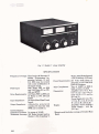
1-1 MODEL L7 LINEAR AMPLIFIER
2-1 REAR CHASSIS CONNECTORS
JUMPER CONNECTIONS FOR 120 VOLT OPERATION.. ...........
JUMPER CONNECTIONS FOR 240 VOLT OPERATION.. ...........
CONNECTING THE PS-7 POWER SUPPLY AND THE R. L.
DRAKE LINE OF COMPATIBLE EXCITERS
VIEWING ANGLE OPTIONS ......................................
FRONT PANEL CONTROLS
L..
PLATE VOLTAGE AND PLATE CURRENT VS 1,000 WATTS
DC INPUT POWER .............................................
SWR NOMOGRAPH ..............................................
COMPONENT LOCATIONS, TOP VIEW..
COMPONENT LOCATIONS, BOTTOM VIEW..
CONNECTIONS FOR GRID CURRENT METER
....
- - .. ~;
r>-...
- ..CALIBRATION ..........................................
MODEL L 7 POWER SUPPLY SCHEMATIC DIAGRAM..
MODEL L 7 LINEAR AMPLIFIER SCHEMATIC DIAGRAM..
Page-ii
..
.................................. 1-2 :'.................................. 2-4 5-'
.z.
2-5
2-5
...................... 2-6
...............
2-7
3-2
..........................
.....................
3-5
3-5
5-5
5-6
....................
.....
.,
............
.........
5-7
5-7
5-9
:'
,
CHAPTER 1
INTRODUCTION
1-1. GENERAL DESCRIPTION
T h e R L. Drake Model L 7 Linear Amplifier offers
con.tinuoas 2000 Watts PEP on SSB, and 1000
Watts DC on CW, AM (controlled carrier) and
RTFY operation covering the ham bands 160
through 15 meters. Non-amateur frequencies
between 1.8 and 21.5 MHz may be covered with
mdi5cation of the input circuit.
The L7 uses 2 zero-bias triodes in a Class B
gmunded-grid circuit configuration that utilizes
RF negative feedback for lower odd-order distortion products. As shipped from the factory, these
tubes will be one of the following listed parts,
which are interchangeable but which are furnished in pairs only:
Amperex 8802/3 - 5002
Amperex 8163
Eimae 3 - 4002
Eimac 3 - 5002
The tnbes are cooled by a quiet, dual-speed internal &we.
A transmitting AGC circuit controls the exciter
gain to allow the highest average power without
peak clipping. Aninternal changeover relay feeds
the antenna through when theL 7 is turned off. A
pair of relay contacts bias the output tubes to cutoff, eliminating unwanted heat and diode noise
when receiving. Twometers indicate plate current,
grid current, plate voltage, RF output power, and
RF reflected power. The separate solid state Power
Supply requires no warm-up period and provides
excellent dynamic and static vol-e
regulation.
1-2. MANUAL COVERAGE
This manual is presented in 5 chapters with supporting illustrations and is arranged for the convenience of the operator and service technician as
follows:
Chapter 1 Introduction (self explanatory).
Chapter 2 Installation. Describes the procedure8
to be followed prior to operation.
Chapter 3 Operation. Illustrates and describes
front panel controls and describes
tune-up and operation in SSB, CW,
RTTY, TUNE and AM modes.
Chapter 4 Theory of Operation. Describes all
critical circuits and networks.
Chapter 5 Maintenance. Provides maintenance
instructions, troubleshooting and
parts ordering information.
'
6 .>-
Fig. 1-1 Model L 7 Linear Amplifier
SPECIFICATIONS
Frequency Coverage: Ham bands 160 through 15
meters. Non-amateur frequencies between 1.8 and
21.5 MHz may be covered
with some modification of
the input circuit.
2000 Watts PEP on SSB
Plate Input:
and 1000 Watts DC on CW,
AM and RlTY.
Drive Requirements: 100 Watts PEP on SSB and
75 Watts on CW, AM and
n m r
IbLLI.
Input Impedance:
Output Impedance:
-
50 Ohms (Band Pass Tuned
Input),
Adjustable pi-network
matches 50 ohm line with
SWR not to exceed 25.
Intermodulation
'' Distortion Products In excess of -33dB.
Wattmeter Accuracy: 300 Watts forward and r e
flected, * (5% of reading + 3
Watts). 3000 Watts forward,
* (5% of reading + 30Watts).
Power Requirements: 240 Volts 50-60 Hertz 15
Amperes, or 120Volts 50-60
Hertz 30 Amveres.
Tube Complement: Two of 3-5062 or 8802/3.-5-00
2 or 8163 or 3-4002.
.Amplifier 1*11/6 in. W x
Dimensions:
6-3/4in. H x 14-1/4in. D.
(34.8 cm W x 17.1 cm H x
36.2 cm D.)
Power Supply 6-3/4in. w x
7-7/8in. H x 11 in. D. (17cm
. Wx20cmHx28cmD.)
Amplifier - 27lbs. (12.25kg.)
Weight:
Power Supply - 42.5 lbs.
Q9.3 kg.)
--
-
* Export model includes coverage of 10meter Ham
Band.
CHAPTER 2
WARNING
The L 7 has been designed incorporating several
interlocks to prevent dangerous electricalshock.
However, it is possible to disconnect the high
voltage terminal while the L 7 is turned on. This
is EXTREMELY DANGEROUS and never
should be attempted for a m reason. When disassembling the L 7, the high voltage terminal
should be disconnected LAST and at reassembly
the high voltage terminal should be connected
FIRST. The L 7 and its Power Supply can be
installed and serviced in complete safety if the
instructions in this manual are followed explicitly. '
2-1. UNPACKING
The L 7 Linear Amplifier is shipped from the factory in 3 separate cartone; 1contains the Amplifier, 1 contains the Power Supply and the third
contains the tubes and the miscellaneous hardware. Carefully unpack all three cartons and
examine their contents for evidence of shipping
damage. If any damage is discovered, notify the
transportation company that delivered the equipment. Be sure to keep the cartons and packing
material as the transportation company will want
to examine them. Keep the carton and packing
even if no shipping damage occurs. Having the
original cartups available simplifies repacking
the equipment for storage or to return it to the
factory for service. Inspect the packing material
closely before storing it to be sure that none of the
accessory hardware has been overlooked. The dismounted components and accessory hardware
shipped with the L 7 should be checked against
the following list.
a . 2 tubes (Amplifier V1 and V2)
b . 2 Plate Caps (for Tubes)
c. (2) 632x518 screws (for Plate Caps)
d . 2 Parasitic Chokes (Note TOP label)
e. (2) 6432x114 Screws (connect Chokes to Caps)
f . 2 Internal Tooth Lock Washm (connect
Chokes to Caps)
g . 2 Cables (1 Vox Relay, 1 Transmit AGC)
h. 1Plug, %Pin (Vox Relay)
i . 2 Resistors, 0.82 Ohm, 2 Watts (&placement
spares for Power Supply R12)
j . 2 Rubber Feet (For Viewing OptionB)
k. 2 studs (to attach rubber feet)
INSTALLATION
1. 1Instruction Manna1 (READZF)
m. 1Warranty F&g&
i ao
ritn
Card
N r n
EFll out the enclosed Warranty Regidrdon
card and return it to the ~ r y h n e d i a t e l y
to insue -tion
and validation of the
warran*.
2-2. TUBE INSTALLATION
WARNING
Tubes must b e M e d and thecabinetreplad
BEFORE ANY C O ~ O N are
S made to
the L 7.
a. Remove the 6 screws which secure the cabinet
to the amplifier and remove the cabinet
b. Refer to fignre+L Insert both tobes into the
sockets on the amplifier ehassia Note the pin
arrangement: Pin 3 is isola6ed.
c . Install the plate caps on the tubes and secure
them with the scsews provided.
d. Attach the parasitic chokes to the top of each of
the plate caps with the screwsand loekwashers
provided. Make sure that the coils of the two
chokes hang DOWN.The word TOP stamped
on each choke musk be visible from the top of
the amplifier.
e. Attach both of theremaining leads ontheparasitic chokes to the top of the plate RF choke
using the 1/420 alnmmmn screw which also
secures one lead from the coupling capacitors.
DO NOT wertighten this screw.
f. Replace the cabinet and secure it with the 6
screws removed in step a
2-3. LOCATION
In general, the location of the L 7 is not Critical;
however, there are certain considerations which
must be given to insure optimum performance.
Care should be taken to insure that a space is provided around the Power Supply case to allow a d e
quate air circulation. Extremely hot locations,
such a s near radiators or heating units, should be
avoided. The back of the Amplifier case
must not be obstructed and should not be placed
closer than 1inch from a wall or the air inlet, for
the blower will be blocked and overheating of the
tubes may occur.
2-4. POWER REQUIREMENTS
2-8. MATCHING NETWORK
The L 7 is furnished with its own separate Power
Supply which can be operated from either 120
VAC or 240 VAC 50-60Hertz. Because of the large
variety of plug and socket configurations for 240
volt service, and because the L 7 can be operated
from either 120Volts or240 Volts, a line plug is not
furnished with the L 7. TheL 7is shippedfrom the
factory with jumpers connected to operate on 240
VAC. It is highly recommended that the L 7 be
operated from its own 240 Volts (15 Amps or
greater) circuit. If a 120 Volt circuit is all that is
available, it should be fused for 30 Amps and the
circuit conductors should not be less than No. 10.
No other equipment should be operated from this
circuit. DO NOT under any circumstances operate
the L 7 from a 120Volt lighting circuit because the
circuit conductors are not large enough to carry
this load safely.
Most practical antennas exhibit an SWR range
over a complete amateur band that exceeds 2:l.
For this reason we recommend using an antenna
matching network such as the R. L. Drake MN2700 which will allow the L 7 to work into a 50
Ohm load for maximum power transfer into the
antenna.
CAUTION
Never attempt to operate the L 7 without first
connecting to a n antenna or 50 Ohm Dummy
Load of sufficient power handling capacity
or serious damage may result.
2-9. GROUND REQUIREMENTS
Figures 2-2 and 2-3 are diagrams of jumper connections required for 120 and 240 Volt operation.
The jumpers in both the Amplifier and Power
Supply must be connected as shown or serious
damage to the L 7 components may result.
For best results, the amplifier should be attached
to a good earth ground through as short and as
large a ground strap as possible. A binding post is
provided on the rear of the amplifier chassis for
the ground connection. I t is always a good idea to
connect the chassis of all associated equipment
together and ground them at one point to avoid
ground loops. We recommend that all of the equipment in your station be connected together and
grounded a t the L 7 Amplifier chassis.
2-6. ANTENNA REQUIREMENTS
2-10. EXCITER REQUIREMENTS
The L 7 has been designed for use with antennas
resonant at the operating frequency and having
approximate impedances within the limits of 25 to
100 Ohms. T)le nominal output impedance of the
amplifier is 50 Ohms and the SWR of this load
should never exceed 23. Although there are many
types of antennas which will meet these requirements, the simplest is a one-half wave dipole
center fed with 52 Ohm coax. For a detailed discussion on antennas, refer to an appropriate
antenna book.
To operate the amplifier at the maximum legal
input the exciter must provide 100 Watts PEP RF
power for SSB operation and 75 Watts RF power
for CW, AM, RTTY and TUNE operation.
Locate the exciter as close to the amplifier as
practical to shorten the coaxial cable and ground
strap. Refer to figures 2-4 and 2-5 for recommended connection arrangements.
2-5. JUMPER CONNECTIONS
2-11. TRANSMITTING AGC
2-7. LOW PASS FILTER
The amplifier has been designed in accordance
with good engineering practices, and harmonic
attenuation meets or exceeds current FCC specifications. Because of the possibility that you may be
qsing a multiband antenna or have afeed line that
is resonant at a harmonic frequency, it is highly
recommended that a suitable low pass filter such
as the R. L. Drake Model TV-3300- be used with
the L 7.
The transmitting AGC voltage, which controls the
gain of the exciter, is presented a t a connector
labeled XMTG AGC OUTPUT on the rear of the
L 7. Any power level can be run up to 2000 Watts
PEP without peak cliGping. A cable is furnished
with the amplifier which provides a connection
to the R. L. DrakePS-7 or AC-4Power Supply. This
connection is routed through the power supply to
the transmitter.
2-12. VOX RELAY
Aphono jack on therearoftheL7AmpMerkpm
vided for connection to a paiT of norma& open
relay contacts in the exciter, which doseontrans
mit and thus turn on the arnpliik ar the same
time The L7 is supplied with a cable with phom,
plugs on each end for this pnrpase AGcandPS7 Power Supplies are equipped ui+h a -'pin
connector instead of a phono jackforthistion. A loose two pin plug is s o p p H ssith t b e C
accessory kit and this plug must be ix&dkd cm
one end of the cable in place of the phmo
when used with these models.
For TR7's and similar e x c b s . ir is
w
observe the correct polar& when t e a l h e
VOX RELAY circuit If a phono conneebris aed
this is automaticall3 a m m p l d u d If a tro pin
connector is used. the wrred polarity is obginsd
with the folloaiing p d m Place rbe &in
STANDBY and set the Li MODE s w i t c h to C X .
the ON/OFF switch to Oh', and the SlBY sricefi
in the "operate" (out) position. Plug in rbe Xi0Z
cable connectors and observe the PlatexMeter. If it reads upscale, reverse the m p i n V 0 X
connector on the exciter end. The ampbfkr p h e
current must be zero with the V05 cable
in and the exciter m STANDBI-.
TYPE
ACCEPTANCE
LABEL
. ....
.:
-.
I
.
.I
I
.~,
.
. .. - . .
-
;
L.
,e;
.
HIGH VOLTAGE
CONNECTOR
J5
-
=
<;,i
.
;
I
n
'
:
CONNECTOR
J4
J6
Fig. 2-1 Rear Chassis Connectors
120 VOLT
Amplifier
OPERATION
Power
Supply
--Figure 2-2.
Jumper Connections for 720 Volt Operation
240
-
..*<:
-
---
..
Power Supply
...-
.
--
?
..-.
-.+-
Figure 2-3.
.
Jumper Connections for 240 Volt Operation
.
:
;
-.
~~
...
.
~
OPERATION
-
Amplifier
-
VOLT
--
..
-
.+ - -
.
-
~~
I.:
.
~
_
-
. .
-
.
Fig. 2-4 Connecting the PS-7 Power Supply and the R. L. Drake Line of Compatible Exciters
OPTION A
i
OPTION B
I N V E R T E D FRONT FEET
mi SUPPLIED
WITH UNIT
SUPPLIED WITH UNIT
Fig. 2-5 Viewing Angle Options
.
>
NOTES
CHAPTER 3
OPERATION
CAUTION
DO NOT turn on the L 7 Amplifier with the
cabinet removed because the high voltage
inter-lock shorts out the B+ and will damage
Power Supply components. DO NOT operate
the Linear Amplifier until it has been
connected to a 50 Ohm antenna or a 50 Ohm
Dummy Load. Be sure that the correctjumper
connections described in Chapter 2 have
-- - been made in both the Linear Amplifier and
the Power Supply for the line voltage to be
used.
3-1. GENERAL
Figure 3-1identifies and describes all front panel
controls and indicators referred to in these tuning
and operating procedures. Perform the appropriate tuning procedures described below prior to
operation.
For all modes of operation, the L 7is tuned up with
a single RF frequency driving it and with the
Mode switch in CW position. The exciter may be
tuned up on CW into the antenna connectedto the
amplifier by depressing the STBY switch. The
exciter should be checked to be sure that itistuned
up when driving the L 7 since the antenna wnnected to the amplser may not be exactly 50
Ohms.
.. 3-2. TUNING PROCEDURE
After the exciter has been tuned up, turn the
exciter to standby andrelease theSTBY switch on
the L 7. Set the Mode switch (red rocker switch) to
CW position. The light that indicates high plate
voltage for SSB operation should be off, and the
OPR light should be on.
The Drake TR 7 and some other exciters utilize
transmitting AGC, sometimes called ALC, during
all modes of operation. During tune up, transmitting AGC will have to be defeated either by unplugging the transmitting AGC connector, or by
turning the AGC control fully counterclockwise.
All Drake Transmitters and Transceivers except
the TR 7 and 2NT (which has no transmitting
AGC) switch off AGC in TUNE, CW and AM
modes. It is not necessary to defeat AGC externally on Drake Transmitters, other than theTR-7.
3-3. CW AND RTTY TUNING
Preset the front panel controls on the L 7 as
follows:
a. Mode switch to CW.
b. Band switch to desired band.
c. Meter switch to 3000 W A m FWD.
d. STBY switch to "operate" (out).
e. LOAD fully counterclockwise to zero.
f . PLATE wntrol in the arc provided for the
desired band.
g. Turn AGC control fully counterclockwise.
h. ON-OFF switch to ON.
Turn on the exciter and increase the exciter output
while not exceeding 0.400 Amperes plate current.
Tune the PLATE control for a dip in plate current.
Alternately adjust the LOAD and PLATE controls
while increasing the exciter power in small increments until maximum RF output occurs at 0.565
plate Amperes. Because of variations in line voltage a graph (figure 3-2)is supplied which correlates plate voltage and plate current for 1000
Watts DC plate input power and should be used to
be sure that the amplifier is operating at or under
the maximum legal input power. In case maximum legal input cannot be obtained because of
low exciter power, tune for maximum forward RF
Watts a t maximum exciter power.
3-4. SSB AND AM TUNING
Preset the front panel controls on the L 7 as
follows:
a. Mode switch to CW.
b. Band switch to desired band.
c. Meter switch to IG (grid current).
d. LOAD control fully counterclockwise to zero.
e Plate wntrol in the arc provided for the desired
band.
f . Turn AGC control fully counterclockwise.
g. STBY switch to "operate" (out).
h. ON-OFF switch to ON.
NOTE
Substitute 250 mA grid current for 200 mA in
succeeding test if 'Amperex 8802/%500Z
tubes are installed in the amplifier.
Turn on the exciter and increase the exciter output
while not exceeding 0.400 Amperes plate current
and tune the PLATE control for a dip in plate current. While increasing the exciter power, maintain
.
-
FIGURE 3-1. FRONT PANEL CONTROLS
I . Multimeter: Indicates plate voltage, grid current, and forward or reflected watts as selected by
meter switches (8).
2. Plate Current Meter: Indicates plate current.
3. Indicator Lamps: Indicate standby or operate condition, SSB (highpower) mode, and multimeter
function.
4. STBY Switch: When depressed, allows standby operation with the exciter connected straight
through to the antenna.
5. AGC Control: Adjusts the transmitting AGC threshold.
6. ON/OFF Switch: Turns the main power on and off.
7. MODE Switch: Selects highplate voltage for SSBoperation or lowplate voltage for CWoperation
o i for tuning.
8. Meter Switches: Select indication for Multimeter (1).
9. PLATE Control: Resonates the plate tank circuit.
10. BAND Switch: Selects input andplate tank components to resonate the amplifier on the selected
band.
11. LOAD Control: Adjusts the output impedance of the amplifier to match the antenna load
: =-.;?
...+
impedance.
-%I.
220 mA of grid current with the LOAD control
until 0.565 plate Amperes is reached. Leave the
exciter power a t this level and redip the plate current with the PLATE control and then bring the
grid current back to 220 mA with the LOAD control. The L 7 will be very close to being tuned up
and only small adjustments of the driving power,
and PLATE and LOAD controls will be necessary
to obtain 0.565 plate Amperes with 220 mA grid
current a t resonance.
The forward power meter is a more sensitive indication of plate tank resonance than plate current
dip, and the PLATE control should be adjusted for
maximum forward power while still maintaining
the relationship of 0.565 plate Amperes to 220 m A
grid current. In case 0.565 plate Amperes cannot
be reached because of low exciter power, tune the
amplifier for maximum forward RF Watts a t
maximum exciter power.
3-5. OPERATION
NOTE
-'
While transmitting with the L 7 over
extended periods of time, the final amplifier
plates may show a bright red color. This is
normal and does not detract from the life of
the tubes. If the plates display a very bright
orange color it is advisable to check the
amplifier to determine that it is not being
overdriven and that it is tuned up properly.
The power should not be turned off
immediately a f t e r long periods of
transmitting, but the amplifier should be left
on standby for several minutes with zero
plate Amperes to allow the final amplifier
tubes to cool down.
3-6. CW AND RTTY OPERATION
For CW and RlTY operation the Mode switch
should be in CW position. With the exciter on and
the key depressed, adjust the drive level until the
product of plate voltage and plate cqrrent is a t or
under maximum legal input power. '
3-7. SSB OPERATION
For SSB operation the Mode switch should be in
SSB position and the red light that indicates high
plate voltage ("SSB") should be on. The transmitting AGC threshold must be set before using
the amplifier. With the Mode switch in CW position the transmitting AGC threshold is adjusted
by applying a strong single audio tone into the
microphone input of the exciter either by an oscillator or by whistling a single tone into the microphone with the exciter adjusted for maximum output. With this single tone applied, turn the AGC
control clockwise until the plate current is 0.580
Amperes. If you desire to run less than 2 kilowatts
PEP, turn the AGC control clockwise until the
single tone plate current decreases to the power
level you desire. Return the Mode switch to SSB.
The AGC threshold needs to be set once on each
band When making large changes in frequency
within a band, the amplifier should be checked for
plate tank resonance while still maintaining the
relationship of 0.565 plate Amperes to 220mA grid
current on CW. Under normal voice operating
conditions, the exciter should be adjusted to run
the L 7 Plate Meter between 0.300 to 0.400 Amperes. Plate current of -.400 Amperes is the maximum legal input allowed and this level should be
reached only occasionally and never exceeded. If
the exciter has no provisions for transmitting
AGC, the output from the amplifier should be
monitored with an oscilloscope to check for peak
clipping.
3-8. AM OPERATION
For AM operation the Mode switch should be in
SSB position and the red light that indicates high
plate voltage ("SSB") should be on. The L 7 works
quite favorably on AM with the compatible Drake
line of Transceivers and Transmitters since these
units use controlled carrier modulation. Transmitting AGC is not used on AM with the Drake
units, and the amplifier output should be monitored with an oscilloscope to check for peak clipping. If the L 7 is to be used with a 100%modulated
AM transmitter, the exciter should be adjusted to
run the amplifier a t 500 Watts DC input with an
unmodulated carrier.
3-9. SWR CALCULATION
The SWR of the load connected to the amplifier
can be determined by using the forward and reflected power readings from the L 7 wattmeter and
the SWR calculator. Refer to figure 3-3. The calculator is used by laying a straight-edge across the
scales a t the forward anclmflected meter readings
and reading the VSWR straightedge. The L 7
wattmeter indicates forward and reflected power
a t all times, so that SWR can be calculated using
only the exciter. For measuring the exciter RF output power a higher degree of accuracy can be
obtained by using the 300 Watt forward scale
instead of the 3000 Watt scale. When returning
the amplifier to service, be sure toreturn theMeter
switch to 3000 Watts or the wattmeter may be
damaged. The amount of RF power delivered to
the load can be determined by subtracting the
reflected power from the forward power.
-.=/''- . ,+
:*
.Jy =--
..>-:
.:
=
..
.
.- .:,
-
-:
:
3-10. OPERATION ON ACCESSORYkyS
2 =i.z
.=...
. ~
..+-4 . .--.. -FREQUENCIES
. .
-.
Bandswitch Position Freauencs in MHz 3:<7.$''
The input coils may be retuned for frequencies
moderately removed from the amateur bands. For
frequencies far removed, it may be necessary to
change the values of the capacitors in the input
circuit.
.-- .. .~~.
.. . .. ..
....
.-..
- -.r= . .- .
. . . . .
.
.: ...T:- i..
7
. .
,-,
.~ A.
. -~
. .. .
=. . ~.
.
. ... . . . .
1000 W a t t s D C . Input
VS
Plate Voltage and Plate Amperes
1900
. . .".'
-
. .. -
.. -.. .
.
-.-
1800
.-.
. ..
PLATE
VOLTAGE
PIATE AMPERES
Figure 3-2.
.
-
-
Plate Voltage and Plate Current VS 7,OYIO Wans DC Input Power
mawup
'OmC
-
Imo 7Q
-
YO-
-
so-
-
¶a-
---P-30-
100
70
V.S.W.I. m r.ntn u-1..
"
SW.R. CALCULATOR
R. I.. DRAKE CO. MIAMISBURG.OHl0
Figure 3-3.
SWR Nomograph
NOTES
CHAPTER 4
THEORY OF OPERATION
4-1. INPUT
4-3. STANDBY CUTOFF BIAS
Refer to the schematic diagrams figures 5-4 and
5-5. The 50 ohm input is matched to the final
amplifier cathodes by a pi-network on each band
which is selected by the input switch S1. Theinput
switch is ganged to the plate circuit bandswitch
SIB. Negative feedback in the L 7 Amplifier is
obtained by slightly raising the grids above
ground with capacitors C19, C20, C21, C24, C25,
and C27.
A positive voltage from the resistor divider, R9,
R10 and R11 in the Power Supply is applied to the
cathode during standby which cuts off the plate
current.
4-4. OUTPUT
The plate circuit is matched to the 50 ohm output
by the adjustable pi-network consisting of L9-L11,
C42, C43 and C46-C50.
4-5. WATTMETER
4-2. TRANSMITTING AGC
When the negative-going peak RF voltage from
the capacitor divider C17 and C18 exceeds the
positive bias set by R4, the transmitting AGC
threshold control, CR1 conducts and a negative
voltage proportional to the RF signal applied to
the input appears a t the transmitting AGC output
connector.
The directional wattmeter basically consists of
L13, C53, C54 and C55, which take the sum and
difference of the transmission line phase voltages
and currents to indicate forward and reflected RF
power. CR4, CR5, C56, C57, R23, R25 and R26
rectify, filter and multiply the basic 200 p A movement of the front panel meter M2 to indicate forward and reflected R F power.
-
NOTES
CHAPTER 5
MAINTENANCE
5-1. SERVICE DATA
Your L 7 will be checked and aligned a t the factory
for a nominal fee if it has not been tampered with.
Transportation charges are extra. Any necessary
repairs will be made on a time and material basis.
Please write or call the factory for authorization
before returning your unit for alignment or service. Address your request for authorization to:
R. L. Drake Company
540 Richard Street
Miamisburg, OH 45342
ATl'N: Customer Service Department
Telephone: (Area Code 513)8663211
CAUTION
DO NOT ship the L 7 with the tubes installed. If
the tubes are in question remove them and r e
pack them separately in their original shipping
containers or obtain new containers from R. L.
Drake Company a t the addresslisted above. The
R. L. Drake Company will not assume responsibility if the transportation company refuses
to pay a damage claim due to improper packing
or lack of insurance.
5-2. PARTS ORDERING
Replacements for any of the components used in
the Amplifier or Power Supply may be ordered, a t
a nominal coqt, from the factory at the address
above. Parts orders should specify that the parts
are for the Amplifier or the Power Supply, the
serial number of the unit, schematic reference
designation of the part, and value, tolerance and
voltage rating, where applicable.
WARNING
DO NOT operate the L 7 with the covers
removed. DO NOT defeat the interlock
LETHAL VOLTAGE is present a t various
points inside the amplifierwhen the interlock
is defeated.
Before disassembling or making any adjustments, perform these precautionary steps in
sequence:
1. Disconnect the Power Supply from the
power source.
2. Disconnect the AC Power connector from
the amplifier.
3. Disconnect the High Voltage connector
from the amplifier.
4. Reverse the above order to reassemble
the Amplifier.
5-3. AMPLIFIER DISASSEMBLY
The cabinet is secured by 6 screws, 3 on each side
of the unit. Remove the screws and lift off the
cabinet.
There are three easily removable plates on the
bottom of the amplifier chassis. The rear plate
(with vent slots) covers the tube sockets and relay
and can be removed by removing the 8 mounting
screws.
The plate behind the POWER and MODE controls allows access to the input low pass filter and
the 120/240 volt filament transformer primary
winding jumpers. It is held in place with five
screws.
Finally, the small plate underneath the bandswitch conceals the input matching network. Unscrew the two mounting screws to remove this
plate.
5-4. CLEANING
Since the Amplifier compartment is forced-air
cooled, it will collect particles of dust which must
be removed periodically. When the fan blade a o
cumlates a large amount of dust, the Amplifier
should be cleaned. The best way to clean the
Amplifier is to remove the cabinet and blow the
dust out with compressed air. If compressed air is
not available, a 1 inch paint brush with soft
bristles may be used to brush the interior clean.
5-5. TUBE REPLACEMENT
If it is neeessary to replace the tubes in theL 7, use
the same brand and typeas the tubes removed or it
may be necessary to retune the input coils a s d e
scribed in paragraph 510.If one tube is replaced
its replacement shouldbethe same brand and type
a s the remaining tube.
5-6. TEST EQUIPMENT
The following list of test equipment represents the
minimum required to test and align the L 7.
a. Ohmmeter
b. 50 Ohm SWR Bridge
c . Standard Milliammeter (400 mA)
d. RF Wattmeter such as R. L. Drake Model WH 7
or an RF Voltmeter such as Hewlett-Packard
Model 410B or Boonton Model 91CA.
e. Transmitter with variable output to 100 W CW
at 14 MHz.
f . 50 Ohm Dummy Load
g. 1-1/2 Volt Battery
h. 10 Ohm Potentiometer
i . Insulated Alignment Tool
5-7. AMPLIFIER TROUBLESHOOTING
Careful consideration has been given to the design
of the L 7 to keep maintenance problems to a minimum. However, it is quite possible that someproblem will arise which cannot be solved by tube substitution. If this occurs, wesuggest that you return
your unit to your dealer, or write directly to theR.
L. Drake Company, Customer Service Department, describing your problem in detail. Include
full information concerning external connections,
control settings, associated equipment and
antenna. Be sure to include the serial number of
the amplifier.
L 7 PLATE VOLTAGE
CW-TUNE
1900 Volts at No Load 1760 Volts at 0.565Amps
SSB
2600 Volts at No Load 2400 Volts at 0.800Amps
L7 IDLING PLATE CURRENT
TUBES
CWTUNE
SSB
Amperex 8802/3-5002 0.100 Amps 0.160 Amos
Amperex 8163
0.100 ~ m p s0.160 Amis
Eimac 3-4002
0.110 Amps 0.170 Amps
Eimac 3-5002
0.170 Amps 0.260 Amps
All tubes above aredirectly interchangeablein the
L 7 and are capable of operating the full legal limit
for amateur service. All voltages and currents
listed above bear a 10%tolerance for tube and line
voltage variations.
5-8. TUBE CHECK
A common failure in the final amplifier tubes is a
filament-to-grid short which is usually intermittent. This failure may be detected by theincidence
of negative grid current (and usually some plate
current) during standby. Check each suspect tube
as follows:
a. Observe the WARNING in paragraph 5 2 and
remove the tubes.
b. Attach an ohmmeter between the grid and fila-
ment of the tube to be tested. Good tubes will indicate infinite resistance. Bad tubes will indicate a
short circuit. Intermittent tubes will indicate a
momentary short when tapped lightly.
5-9. ALIGNMENT PROCEDURES
Refer to figures 5-1and 5-2 as required to locate the
components requiring adjustment.
5-10. INPUT COIL ADJUSTMENT
The input coils may have to be retuned if the final
amplifier tubes are replaced with a type different
from the tubes removed. Also, they may have to be
retuned if it is desired to operate the amplifier
outside the amateur bands. To retune the input
coils proceed as follows:
a . Disconnect the L 7 Power Supply from the
power source.
b. Remove the bottom cover from the Power
Supply.
c . Remove all of the jumpers from the 7-terminal
barrier strip in the power supply. This allows
the filaments, relay power and blower to
operate without the high voltage being on.
d . Remove the cabinet from the Amplifier. DO
NOT defeat the interlock.
e. Connect the Amplifier to the exciter as for
normal operation EXCEPT: insert a 50 Ohm
SWR bridge in the line (R. L. Drake WH-7 or
eaual).
f . g e s e t the amplifier controls as follows:
BAND: on band to be tuned.
LOAD: fully counterclockwise to zero.
STBY: released (out)
ON-OFF to OFF.
g . Tune the exciter, on CW, to the middle of the
band to be tuned.
h . Reconnect the Power Supply to the power
source.
i . Turn on the L 7 and increase the outaut from
the exciter until the Plate meter reads 0.400
Amperes.
j . Tune the PLATE control for a dip in plate
current.
k . Refer to figure 5-1. Turn the slug in the correct
input coil for a minimum reflected power reading on the SWR bridge.
1. Repeat steps f through k for each coil to be
retuned.
NOTE
As shipped from the factory, the input coils
are adjusted for the center of each band and
are broad enough to cover the entire band.
m. Turn off the Amplifier, disconnect the Power
Supply from the power source, replace the
jumpers removed in step c above, remove the
SWR bridge and replace the covers on the
Power Supply and the Amplifier before resuming operation.
5-1 1. METER ADJUSTMENT
To adjust the meters on the front panel of the L 7
proceed as follows:
a. Disconnect the Power Supply from the power
source.
b. Remove all connections to the amplifier.
c. Take the cabinet off theL 7 by removing the six
screws that secure the cabinet on the bottom of
the amplifier.
d. Each meter has a conventional zero-adjust
screw on the lower face of the meter and may be
set to zero with that screw. To access these
screws, remove the meters by unscrewing the
two mounting tabs on each side of each m e w .
e. If resistor R20 is replaced thegrid current shunt
R16 will have to be calibrated as follows:
1. Defeat the interlock on the top of the chassis
by placing a book on top of theoperatingrod
(NO CONNECTIONS TO AMPLIFIER).
2. Set the Meter switch to GRID CURRENT.
3. Make the connections show in figure 5-3.
4. Adjust the 10 Ohm pot until the milliammeter indicates 0.400 Amperes.
5. Adjust R19 until the Grid Current meterindicates 400 mA.
6. Disconnect the test network.
F. If a milliameter is not available, a n alternate
z.
i.
t.
h o d of calibrating R19 is as follows:
1. Defeat the interlock (NO CONNECTIONS
TO AMPLIFIER).
2. Reverse the wires connected to the Plate
Meter MI.
3. Connect a 1-1/2 Volt battery (negative to
ground) in series with a 10 Ohm potentiometer to pin 6 of the Power connector 54 on
the rear of the amplifier.
4. Adjust the 10 Ohm pot until the Plate Meter
indicates 0.400 Amperes.
5. Adjust R19 until the Grid Current meter indicates 400 mA.
6. Disconnect the test network and reverse the
wires on the Plate Meter to their original
locations.
g. The high voltage adjustment potentiometerRl7
is not user adjustable. If this needs readjustment, return the L 7 to the factory for service.
See paragraph 5-1.
-- -
5-12. WATTMETER CALIBRATION
The wattmeter in the L 7 was designed to keep
maintenance to a minimum. The wattmeter is a
passive device, and it should provide years of
service and maintain its calibration. If calibration becomes necessary, paragraphs 5-13through
5-16 must be followed in sequence.
5-13. NULL ADJUSTMENT
WARNING
When making adjustments to the Wattmeter with the exciter on, exercise
EXTREME CAUTION to avoid RF
burns. Avoid touching the Piston Trimmer C53, the Antenna Changeover
Relay RLYl and all wires connected
to it.
a. With the L 7 completely disconnected, turn it
upsidedown and remove the rear bottom cover.
b. Connect the exciterto the RFINPUT and the 50
Ohm Dummy Load to the RF OUTPUT.
c. Set the L 7 Meter switch on REF 300.
d. Apply between 100and 300 Watts of power a t 14
MHz.
e. With the insulated alignment tool adjust the
piston trimmer C53 for a minimum indication
of reflected power.
f . All further adjustments should be made with
the L 7 in its normal upright position.
5-14. 300 WATTS REFLECTED
a. Connect the exciter to the RF OUTPUTand the
R F INPUT to a Wattmeter (Drake WH 7) and
then to a 50 Ohm Dummy Load.
b. Set the Meter switch to REF 300 and apply 300
watts from the exciter. If 300 watts is not available, adjust the exciter for maximum RF output.
c. Adjust R24 so that the L 7 wattmeter agrees
with the standard wattmeter or with the R F
power calculated from the RF voltage measured
across the 50 ohm load.
5-15. 300 WATTS FORWARD
a. Connect the L 7 a s i n thenull adjustment (paragraph 5-15), and inclhde a wattmeter (Drake
WH-7) between RF OUTPUT and the 50 Ohm
load. Place the Meter switch on FWD 300 and
apply 300 watts from the exciter. If 300 watts is
not available, adjust the exciter for maximum
RF output.
b. Adjust R23 so that the L 7 wattmeter agrees
..
.. -.
p
. ., .
with the standard wattmeter or with the RF
power calculated from the RF voltage measured across the 50 Ohm load.
After completely disconnecting all sources of
power, the bottom cover of the Power Supply can
be removed by taking out all of the screws around
the bottom of the chassis.
5-16. 3000 WATTS FORWARD
a. After the 300 watts forward calibration, set the
L 7 bandswitch to 20 meters and tune it up as
described in Chapter 3, "Operation." Place the
meter switch in the FWD 300 position adjust
the exciter for 1000 watts output from the
amplifier.
b. Adjust R26 so that the L 7 wattmeter agrees
with the standard wattmeter or with the RF
power calculated from the RF voltage measured
across the 50 ohm load.
5-17. KNOB POINTER ALIGNMENT
When replacing the knobs on the L 7 amplifier,
correct alignment of the PLATE and LOAD controls is important. All of the other controls have
flats on the control shafts and the setscrewsin the
knobs should press against the flats. The PLAT%
and LOAD control shafts should be rotated so that
the plates of the variable capacitor are fully
meshed, and the pointer should be resting in a
nine o'clock position at the end of the tuning arc.
5-18. POWER SUPPLY C l R C U l i
BREAKER RESET
There are twabuttons on the power supply which
are provided for resetting the circuit breakers in
case they should trip from overloading. If the
circuit breakers trip, turn off the amplifier and
wait for one minute before resetting. If the circuit
breakers trip immediately after resetting and
turning the amplifier on, an investigation should
be made to determine the cause of the overload.
5-19. REMOVING THE BOTTOM
COVER
WARNING
BE SURE that the L 7 Power Supply is unplugged from its power source.
5-20. REMOVING TOP COVER
WARNING
BE SURE that the L 7 Power Supply is unplugged from its power source.
The top cover cannot be removed until the bottom
cover has been removed. After the bottom has
been removed, remove the line cord wires from the
barrier strip and ground. The top can then be r e
moved by taking out the remaining screws
holding the top cover to the chassis.
5-21. POWER SUPPLY TROUBLESHOOTING
Careful consideration has been given to the design
of the L7 Power Supply to keep maintenance
problems to a minimum. However, if the Power
Supply fails to function, first check the circuit
breakers and reset them if it is necessary. If the
circuit breakers continue to trip, check for short
circuits in the high voltage line. Especially be
certain that the high voltage interlock in the
Amplifier is not shorting the high voltage to
ground as it is supposed to do when the top cover
is taken off the amplifier. If the circuit breakers
have been tripped because of a short in the high
voltage line, a continuity check should be given
to each silicon diode bank in the Power Supply to
determine if either or both banks have failed. In
the event of a short circuit, resistor R12 in the
Power Supply will be destroyed. This resistor protects the diodes in the Power Supply and it should
be replaced with an IRC 0.82 Ohm 2 Watt type
BWH resistor ONLY. In the event of a difficulty
we recommend that you return your unit to your
dealer, or write directly to our Customer Service
Department describing your problem in detail.
Include full information concerning the circumstances during the failure, any measurements
that were made and be-sure to include the serial
number.
PARASITIC CHOKES
(PC-1, PC-2)
RF PLATE CHCUE
(RFC-4)
-
GRID &RENT
CAL. POT. R-19
Fig. 5-1 Component Locations, Top View
\
C42
I
120/22(1V mMINAL STRIP
(SEE FIG 2-3)
\
LOW P A S
FILERS
FILTER
Fig. 5-2 Component Locations, Bottom View
1.5 VOLT
L 7 CHASSIS
10n POT
TEST PT. A
M
0-400 MA
MlLLlAMMETER R,
PUSH BUTTON
BOARD
Fig. 5-3 Connections for Grid Current Meter Calibration
RtJ TNmU llf 6
I R E I S O X , HY
7w
I20 V
ISA
QR 24OV
Ra
POWER
@POWER
LINE
GND
POWER CONNECTOR SHOWN
FROM SOLDER CONNECTION E N D
Fig. 5 4 Model L 7 Power Supply Schematic Diagram
NOTES
..
Cornp~nsntLocations
35
2 4
.i
2
1
R
A2
3
4
7
8 11
8 13
12
14 9
28
16
17 I8
6
"28
22
25
4 8
5
7 8
8
30 21
68 24
z7
7
30
SO
28
27
8
32 80
35 38
34
37
11
9
10
2o
36 39 41 45
58 40 44 61 48
9 11
10
.
12
47
13 14::
81
52
15 17
48 42 43
48 50
22
2
5
:
;
21 24
63 5654 6268
27
28
6367
15
NOTE
17 UNEAR AMP Schemrtic
Wpadtmlnarked1.Om2400arehpl.~dC.p.cltor.n*r*.d.W1to.l uahmfd-emr*rluraMd.
Fig. 5-5 Model L 7 Linear Amplifier Schematic Diagram
.?
nr
Dwg +D4788