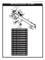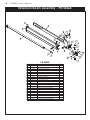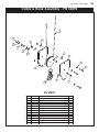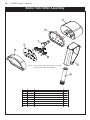
1
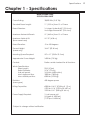
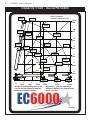
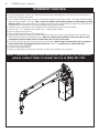
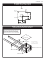
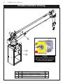
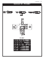
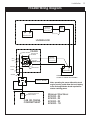
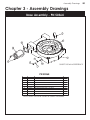
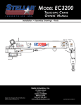
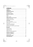
MODEL EC6000
TELESCOPIC CRANE
OWNERS’ MANUAL
Installation • Assembly Drawings • Parts
2720 kg
Reach in Feet/Meters
Capacity in Pounds/Kilograms
6000 lbs
2720 kg
22'10"
6.96m
Angle Indicator
3600 lbs
1630 kg
2720 kg
6000 lbs
18'
5.49m
2545 lbs
2720 kg
1150 kg
4715 lbs
2135 kg
2080 lbs
1510 kg
6000 lbs
940 kg
2720 kg
12'
3.66m
6000 lbs
75º
2720 kg
60º
2730 lbs
4845 lbs
1235 kg
2195 kg
45º
DANGER
845 kg
2450 lbs
6'
1.83m
1110 kg
3560 lbs
1610 kg
Electrocution Hazard
3'
.914 m
3450 lbs
1560 kg
3'
.914 m
6'
1.83m
9'
2.74m
11'
3.35m
2375 lbs
1075 kg
16'
4.87m
1810 lbs
820 kg
Death or serious injury will result from
inadequate clearance if crane, load,
or vehicle becomes electrically
charged.
0'
21'
6.40m
Maximum 1 - part line capacity is
3000 lbs (1360 kg). For greater loads,
use 2 - part line.
EC6000
EC
6000
• Maintain safe clearance from high
voltage power sources.
50
15º
0'
Weight of load handling devices are
part of the load lifted and must be
deducted from the capacity.
60
1795 kg
35234
9'
2.74m
1870 lbs
3965 lbs
30º
Proudly Designed
and Manufactured
in the USA by
80 70
15'
4.57m
3340 lbs
2720 kg
40
30
20
• Never approach vehicle or load if
equipment is near a high voltage
power source.
10
0
13820
6000 lbs
6000 lbs
6000 lbs
80º
C1179
PN 53525
EC6000
EC
6000
WARNING
Free Falling Boom Hazard
Free falling manual boom
extensions can result in death or
serious injury.
• Properly install retention pins
prior to operation.
• Do not stand in front of
extension when removing
retention pin.
• Do not allow extensions to
free fall.
12452
WARNING
WARNING
Fall Hazard
• Never use crane to hoist
personnel.
• Never ride the boom, hook,
load, or any device attached
to crane boom or load line.
12451
WARNING
Winch
Boom
Down
Pull
g
Boom
Hoisting personnel on boom,
hook, load, or loadline can result
in death or serious injury.
53524
Extendin
Misuse Hazard
Two blocking the crane can result in death
or serious injury.
Never allow the hook block to contact the
boom tip by hoisting up, extending or
lowering the boom.
12300
Misuse Hazard
NOTICE
Do not use stow hook for any lifting applications.
Using the stow hook for anything other than hook
stowage can result in death or serious injury.
This crane has been designed and
manufactured to ASME/ANSI B30.22
and/or B30.5 specifications.
12924
24712
G
WARNIN
Hazard
Overload
condition
the overload
Bypassing
with the overload
or
by tampering
result in death
device can
serious injury.
with overload
Never tamper
device.
NOTICE
Damage may occur if worm gear runs
dry. Keep worm gear lubricated with
Stellar® grease (PN 4460).
9188
28256
GREASE every 3 months.
Apply 3 ‘pumps’ of EP2
(extreme pressure grease)
then rotate crane fully.
15171
LOAD BLOCK RATING
3 Tons
(2,721 KG)
SNATCH BLOCK WEIGHT: 15 LBS (6.80 KG)
42819
Stellar Industries, Inc.
Subject to Change without Notification.
© 2013 Stellar Industries, Inc.
190 State Street
PO Box 169
Garner, IA 50438
800-321-3741
Fax: 641-923-2811
www.stellarindustries.com
Last Revision: 07/24/13
EC6000 Manual Revisions
Date of Revision
March 25th, 2013
Sections Revised
Chapter 2: Installation
Description of Revision
Updated Decal Kit
Table of Contents
Table of Contents
Chapter 1 - Specifications . . . . . . . . . . . . . . . . . . . . . . . . . .1
Capacity Chart - Decal PN 53525 . . . . . . . . . . . . . . . . .2
Chapter 2 - Installation . . . . . . . . . . . . . . . . . . . . . . . . . . . . .3
Installation Overview . . . . . . . . . . . . . . . . . . . . . . . . . . . .4
Flatbed Body Reinforcement . . . . . . . . . . . . . . . . . . . . .5
EC6000 Mounting Detail . . . . . . . . . . . . . . . . . . . . . . . . .5
EC6000 Installation Drawing . . . . . . . . . . . . . . . . . . . . . .6
Hydraulic Kit - PN 54857 . . . . . . . . . . . . . . . . . . . . . . . . . .7
Control Kit - PN 54859 . . . . . . . . . . . . . . . . . . . . . . . . . . .8
EC6000 Wiring Diagram . . . . . . . . . . . . . . . . . . . . . . . . . .9
Valve Bank Drawing . . . . . . . . . . . . . . . . . . . . . . . . . . . .10
Stability Procedure . . . . . . . . . . . . . . . . . . . . . . . . . . . . .11
Stability Capacity Chart . . . . . . . . . . . . . . . . . . . . . . . .12
Decal Kit Placement - PN 53523 . . . . . . . . . . . . . . . . . .13
Chapter 3 - Assembly Drawings . . . . . . . . . . . . . . . . . . . .15
Base Assembly - PN 50364 . . . . . . . . . . . . . . . . . . . . . . .15
Mast Assembly - PN 53379 . . . . . . . . . . . . . . . . . . . . . . .16
Main Boom Assembly - PN 53223 . . . . . . . . . . . . . . . . .17
Extension Boom Assembly - PN 53264 . . . . . . . . . . . . .18
Cable & Hook Assembly - PN 50492 . . . . . . . . . . . . . . .19
Radio Transmitter Assembly . . . . . . . . . . . . . . . . . . . . . .20
Chapter 4 - Replacement Parts . . . . . . . . . . . . . . . . . . . . .21
Find a Dealer Near You:
http://www.stellarindustries.com/pages/dist/distsearch.htm
For Technical Questions, Information, Parts, or Warranty, Call Toll-Free at
800-321-3741
Hours: Monday - Friday, 8:00 a.m. - 5:00 p.m. CST
Or email at the following addresses:
Technical Questions, and Information
Order Parts
Warranty Information
[email protected]
[email protected]
[email protected]
i
ii
EC6000 Owner’s Manual
About this manual
A copy of this manual is provided with every crane and can be found in the hard plastic
manual case that is installed on the chassis. A copy of this manual shall remain with the
crane at all times.
Throughout the manual, three signal words will be used to bring attention to important
items:
A NOTICE signal word indicates a practice not related to physical injury.
A WARNING signal word indicates a hazardous situation which, if not
avoided, could result in death or serious injury.
A DANGER signal word indicates a hazardous situation which, if not
avoided, will result in death or serious injury.
Information contained within this manual does not cover operation, maintenance, or
troubleshooting. Please refer to the General EC Series Crane Manual for details on these
items.
This manual is not binding. Stellar Industries, Inc. reserves the right to change, at any time,
any or all of the items, components, and parts deemed necessary for product
improvement or commercial/production purposes. This right is kept with no requirement or
obligation for immediate mandatory updating of this manual.
If more information is required or technical assistance is needed, or if you feel that any
part of this manual is unclear or incorrect, please contact the Stellar Customer Service
Department by phone at 800-321-3741 or email at [email protected].
Chapter 1 - Specifications
Crane Rating:
Specifications
Model EC6000 Crane
SPECIFICATION SHEET
Standard Boom Length:
Boom Extension:
Maximum Horizontal Reach:
Maximum Vertical Lift:
(from crane base)
38,000 ft-lb (5.25 TM)
11’ (3.35 m) from CL of Crane
1st stage: Hydraulic 60" (152.4 cm)
2nd stage: Manual 60" (152.4 cm)
21’ (6.40 m) from CL of Crane
22’ 10” (6.96 m)
Boom Elevation:
-5 to +80 degrees
Mounting Space Required:
20” x 21” (50.8 x 53.3 cm)
Controls:
Radio control standard for all functions.
Stowed Height:
(crane only)
Approximate Crane Weight:
Winch Specifications
Rope Length:
Rope Diameter:
Line pull speed:
Max. single part line:
Max. double part line:
Rotation:
(worm gear)
Lifting Capacities:
Power Supply Required:
*Subject to change without notification
34.41” (87.40 cm)
1600 lbs (725 kg)
90 ft (27.4m)
5/16" (.79 cm)
16 ft/min (4.88 m/min)
3000 lbs (1360 kg)
6000 lbs (2720 kg)
400 degree power
6000 lbs @ 6’4” (2720 kg @ 1.9 m)
2375 lbs @ 16’ (1075 kg @ 4.87 m)
1810 lbs @ 21’ (820 kg @ 6.4 m)
12 volt power unit
(2.0 gpm @ 2900 psi)
(7.57 lpm @ 200 bar)
1
2
EC6000 Owner’s Manual
Capacity Chart - Decal PN 53525
6000 lbs
2720 kg
Reach in Feet/Meters
Capacity in Pounds/Kilograms
6000 lbs
2720 kg
22'10"
6.96m
3600 lbs
1630 kg
18'
5.49m
6000 lbs
2720 kg
6000 lbs
2545 lbs
2720 kg
1150 kg
4715 lbs
2135 kg
15'
4.57m
3340 lbs
6000 lbs
2720 kg
80º
2080 lbs
1510 kg
6000 lbs
12'
3.66m
940 kg
2720 kg
6000 lbs
75º
2720 kg
60º
2730 lbs
4845 lbs
1235 kg
2195 kg
45º
1870 lbs
3965 lbs
1795 kg
9'
2.74m
845 kg
2450 lbs
30º
6'
1.83m
1110 kg
3560 lbs
15º
1610 kg
3'
.914 m
3450 lbs
1560 kg
0'
3'
.914 m
6'
1.83m
9'
2.74m
Weight of load handling devices are
part of the load lifted and must be
deducted from the capacity.
11'
3.35m
2375 lbs
1075 kg
16'
4.87m
1810 lbs
820 kg
0'
21'
6.40m
Maximum 1 - part line capacity is
3000 lbs (1360 kg). For greater loads,
use 2 - part line.
EC6000
EC
6000
PN 53525
Chapter 2 - Installation
Installation
3
General Installation
This chapter is designed to serve as a general guide for the installation of a Stellar EC6000
Crane on a Stellar Service Body. Each installation is considered unique so certain portions
of this chapter may or may not apply to your direct application. If a question should arise
during the installation process, please contact Stellar Customer Service at (800) 321 3741.
This crane is designed for use with a Stellar Service Body installed on a vehicle that meets
the minimum chassis requirements of the crane. It is the installer’s responsibility to assure
that the crane is mounted on a platform that will support the maximum crane rating of this
crane.
Do not install this crane on a body not capable of handling the loads
imposed on it. Failure to do so may result in serious injury or death.
When installing welder units to the service bodies, it is highly
recommended that a surge protector is installed on the chassis batteries to protect the
crane radio receiver, wiring and other electronic devices from an unexpected electrical
spike or surge. Failure to do so could result in extensive damage to the service body and
crane electrical circuit.
Installation Notice
According to Federal Law (49 cfr part 571), each final-stage manufacturer shall complete
the vehicle in such a manner that it conforms to the standards in effect on the date of
manufacture of the incomplete vehicle, the date of final completion, or a date between
those two dates. This requirement shall, however, be superseded by any conflicting
provisions of a standard that applies by its terms to vehicles manufactured in two or more
stages.
Therefore, the installer of Stellar cranes and bodies is considered one of the manufacturers
of the vehicle. As such a manufacturer, the installer is responsible for compliance with all
applicable federal and state regulations. They are required to certify that the vehicle is in
compliance with the Federal Motor Vehicle Safety Standards and other regulations issued
under the National Traffic and Motor Vehicle Safety Act.
Please reference the Code of Federal Regulations, title 49 - Transportation, Volume 5 (400999), for further information, or visit http://www.gpoaccess.gov/nara/index.html for the full
text of Code of Federal Regulations.
4
EC6000 Owner’s Manual
Installation Overview
1. Determine that the mounting location for the EC6000 crane is at least 18” x 20” (45.7 x 50.8 cm).
2. Use the detail below to drill 1.06” diameter holes into the mounting plate. Run tap on the threads of the
base to be sure they are clean.
3. Use a crane or lifting device capable of lifting the weight of the Stellar crane. The Stellar EC6000 weighs
approximately 1600 lbs (725 kg). Note: cranes are shipped with rotation positioned at 200 degrees of 400
degree system. This will allow for easy installation of the crane and permanent connection of all hydraulic
and electrical components prior to repositioning into the crane saddle.
4. Connect straps or chain from the lifting device to the lifting rings on the Stellar EC6000.
5. Use four (4) 1” x 3” Grade 8 bolts and four (4) 1” Grade 8 flat washers.
6. Install a washer on each bolt.
7. Apply Loctite Thread locker #277 to the bolts.
8. Using the lifting device, lower the Stellar EC6000 just above the crane compartment and start the bolts.
Have someone assist in leveling the crane. Note: the rotation motor should be to the door side of crane
compartment and the boom should be extended back over the rear bumper.
9. Secure the crane using the mounting hardware provided. Note: longer or shorter bolts may be required –
recommended thread engagement into crane base is 1.75” – use grade 8, zinc plated bolts only.
10. Torque the bolts to 680 ft-lbs.
11. Remove supporting crane.
12. Hook-up hydraulics and electrical using the schematics provided in this chapter.
Note: If questions should arise during any portion of this installation,
please contact Stellar Customer Service at (800) 321-3741.
Installation
EC6000 Mounting Detail
FRONT
Motor
Ø1.063
4 Places
14.75
Ø6.00
7.38
7.38
14.75
Hole Mounting Detail
Flatbed Body Reinforcement
If it has been determined that the destination
body won’t support the crane with a fully
rated load, the body must be reinforced.
Use 1/4” fillet welds and an AWS qualified
welder to proceed as shown in this drawing:
3/8 PLATE
TUBE 4X2X0.38
Note: Tubing must be
at least 4” x 2” x 0.38”
(Except where noted)
TUBE 2X2X0.38(TYP 4)
TRUCK FRAME
TUBE 4X2X0.38
5
6
EC6000 Owner’s Manual
EC6000 Installation Drawing
4
3
2
ITEM
2
3
4
PART
5199
6538
53376
NOTICE!
Route hoses correctly to ensure
they do not become pinched or
crushed during installation.
DESCRIPTION
CAP SCR 1.00X8X3.00 HHGR8 ZY
WASHER 1.00 SAE FLAT YELLOW GR8
CRANE EC6000
QTY.
4
4
1
Hydraulic Kit - PN 54857
PN 54857
Installation
7
EC6000 Owner’s Manual
Control Kit - PN 54859
Replacement Controller
Stellar PN 54862
POWER
GROUND
OPT1
OPT2
8
PN 54859
NOTE: P/N 54860 INCLUDES
HARNESS & WINCH CONTROLLER
Installation
EC6000 Wiring Diagram
FUSE 300 AMP
PN 54918
MASTER
SWITCH
250 AMP
Holder: PN 32523
(STELLAR SUPPLIED)
-
+
(NOT SUPPLIED)
TRUCK BATTERY
UNDERHOOD
CRANE HARNESS
CRANE
START MOTOR
SOLENOID
FUSE 300 AMP
PN 54918
OPT1
Holder: PN 32523
Torque Spec
Large Nuts: 35 in-lbs
Small Nuts: 15 in-lbs
OPT2
(STELLAR SUPPLIED)
GROUND
GROUND
GROUND POST
POWER
-
+
AUX BATTERY
GROUND
LOCATE AUX BATTERY AS
CLOSE TO CRANE AS POSSIBLE
87
SAFETY BRAKE
87A
86
30
SWITCH
POWER
10 AMP
85
Note: operating the crane without the truck
engine running could allow the truck battery
to be discharged below levels required for
starter cranking power.
POWER SOURCE FOR
RADIO REMOTE
CAB OR CRANE
COMPARTMENT
Minimum Wire Sizes:
EC3200 - #2
EC4000 - #2
EC5000 - #2
EC6000 - 1/0
9
10
EC6000 Owner’s Manual
Valve Bank Drawing
ROT
CW
INNER
DOWN
EXT
IN
ROT
CCW
INNER
UP
EXT
OUT
Stability Procedure
Installation
11
Definition of Stability for the Stellar Telescopic Crane Products:
A truck is stable until the load cannot be lifted off the ground with the winch, without
tipping over the truck. Every Stellar crane installed must be tested for stability to
determine the actual load capacity of the final truck package. The actual test data
must be recorded and supplied with the truck at the time of in-service and should be kept
with the truck at all times. The following procedure will test the truck package for stability
and will provide a stability capacity chart. The load limit information shown on the
stability capacity chart is formulated on 85% tipping.
Set Up:
1. Locate the truck on a test course in position for loading and engage travel brakes.
2. Set stabilizers so that they make contact with firm, level footings.
3. Operate the crane under partial load to assure operator proficiency and proper
machine function.
EC6000 Stability Data
Max Horizontal Reach: 252” (From the center of rotation to boom tip)
Stability Test Weight: 2135 lbs.
Test Procedure
1. Rotate the crane into Zone 1 position.
2. With the crane fully retracted and the boom horizontal, winch the test weight off the
ground. Note: Keep weight within six inches of the ground at all times.
3. Extend the boom outward until full extension has been reached or until the truck
becomes unstable (Again, use the winch to keep the weight within six inches of the
ground.)
4. If the boom goes full extension without becoming unstable, the crane is termed stable
for this zone and 100% can be written in the Zone 1 data box.
5. If the truck becomes unstable prior to going full extension, retract the boom until the
truck becomes stable and measure the horizontal reach in this position (center of
rotation to boom tip). This is the stable horizontal reach for this zone. Stable horizontal
reach divided by Maximum horizontal reach multiplied by 100 equals the percentage
of rated capacity for this zone. Use the following formula to determine the percentage
of rated capacity:
6. Record this number in the data box for Zone 1. This is the revised capacity due to
stability for this zone.
7. Repeat this procedure for each zone until the worksheet is completed.
8. This is the revised capacity based on stability of this package.
12
EC6000 Owner’s Manual
Stability Capacity Chart
STABILITY CAPACITY CHART
For a decal version of this capacity chart, please contact Stellar Customer Service at (800) 321-3741
Decal Placement Kit - PN 53523
13
2720 kg
2720
22'10"
6.96m
6.96m
3600 lb
llbs
Angle Ind
Indicator
icator
1630 kg
18'
5.49m
5.49m
6000 lb
llbs
2545
5 llbs
lbs
2720
27
720
20 kg
1150
11
150
50 kg
4715 lb
llbss
2135
2135 kg
15'
4.57m
4.57m
3340 lb
llbss
6000 llbs
b
2720 kg
2720
2080
0 lb
llbss
1510
1510 kg
6000 lb
llbs
80º
12'
3.66m
3.66m
940
9
40 kg
2720
27
20 kg
6000
0 lb
llbss
75º
Proudly
Pr
oudlyy Designed
Designed
and Manufactured
Manufactured
in the USA by
by
2720 kg
60º
2730 lb
llbss
lb
4845 lbs
1235
12
35 kg
2195
21
95 kg
45º
845
845 kg
2450 llbs
b
6'
1.83m
1.83m
1110
1110 kg
3560 lb
llbss
3'
914 m
..914
3450
0 lb
llbss
1560
15
56
60 kg
0'
3'
914 m
..914
6'
1.83m
1.83m
35
35234
234
DANGER
1610
1
10 kg
9'
2.74m
2.74m
e
Weight
We
igh
ght off lo
load
ad ha
handling
ndlin
ing
g de
devices
vice
ces ar
are
p
art o
e lo
ad lifted an
d mu
st b
e
part
off th
the
load
and
must
be
d
educted fr
om
m the
th
t e capacity.
capacity.
deducted
from
11'
3.35m
3.35m
2375
5 lb
llbss
10
075
75 kg
1075
16'
4.87m
4.87m
1810 llbs
bs
20 kg
820
0'
21'
6.40m
6.40m
Ma
Maximum
ximu 1 - p
part
art lin
line
e cap
capacity
pac
acity is
3000
kg).
For
greater
3
000 lbs
bs ((1360
1360
60 k
g). F
or g
reater loads,
lloa
oads,
u
se 2 - p
art lin
li
e.
use
part
line.
EEC6000
C6000
00
0
Electrocution
Electrocution Hazard
ous injur
y will rresult
esult ffrom
rom
De
Death
ath orr seri
serious
injury
in
adequate clearance if crane, loa
d,
inadequate
load,
or vehicle becomes electr
ically
electrically
char
ged.
charged.
• Main
tain ssafe
afe clearance
clearance ffrom
rom hi
igh
gh
Maintain
high
voltage power sou
rces.
sources.
• Never ap
proach veh
icle or load if
approach
vehicle
equ
ipment
nt is near a high volt
tage
age
equipment
voltage
pow
er source.
power
PN 5
53525
3525
C1179
C11
1179
18
50
15º
15
600
1795
1795 kg
9'
2.74m
2.74m
1870 lb
llbss
3965 lbs
lbs
30º
80
80 70
17
40
30
20
10
04
16
06
Reach in FFeet/Meters
eet/Met
e
t/Met
eters
ers
Capacity
Pounds/Kilograms
Capacit
y in Pou
nds/K
s/Kilogram
ilograms
6000 lb
llbs
2720 kg
2720 kg
2720
0
13820
13820
6000 llbs
b
6000 lb
llbs
13
Installation
EEC6000
C6000
00
0
02
WARNING
WARNING
Free
Fr
F
ee Falling
Falling Bo
Boom
oom Ha
Hazard
aza
ard
a
Free
boom
Fr
ee ffalling
alling manual bo
om
extensions
ex
tensions can
can result
result in death
death or
erious injury.
sserious
injury.
• Properly
Properly install
in
n tall retention
ret ntiion pins
prior
prior to
to operation.
operattion.
ion.
• Do
Do nott stand
stand in front
front of
extension
when
ex
tension w
hen rremoving
emoving
rretention
et ntion
ion pin.
• Do
Do nott allow extensions
extensions to
to
free
free fall.
fall.
1
12452
2452
WARNING
W
ARNING
nch
Win
Winch
W
WARNING
ARNING
Boom
B
oom
Down
Down
Pu
Pull
g
dinn
xten
E
Extending
om
Boom
B
Fall
F
all H
a
Hazard
aza
a
ard
rd
Hoist
Hoisting
stin
in
ng p
personnel
on
boom,
ersonnel o
nb
oom,
hook,
orr loadl
loadline
hook, load, o
line
ine ccan
an rresult
esult
death
injury.
in deat
th
h or sserious
errious
ious injur
y.
Misu
Misuse
se H
Hazard
azard
• Never use
hoist
se crane
crane tto
o ho
ist
personnel.
personnel.
53524
10
NOTICE
This crane has been desi
designed
igned
gned and
manufactured to ASME/ANSI B30.22
and/or B30.5
. specificati
ions.
ons.
specifications.
129
12924
24
T
Two
wo blo
blocking
cking
g tthe
he cr
crane
ane can result
esult iin
nd
death
eat
ath
or sserious
erio
ous in
njur
jury.
injury.
boom,, hoo
hook,
he boom
k,
• Never ride
ide tthe
load,
device
attached
load, or any devic
ea
att
ached
tto
o ccrane
rane boom or load line.
he
Ne
ver a
llow tthe
he h
ook blo
ock tto
o con
tact tthe
Never
allow
hook
block
contact
bo
om
o
m ttip
ip by ho
isting u
p, ext
endin
ng
g or
boom
hoisting
up,
extending
lo
wering
wer
ing the
the boo
om
o
m.
lowering
boom.
12451
12300
1
300
W
WARNING
ARNING
Mi
Misuse
suse H
Hazard
azard
Do
Do not
not use
usse stow
stow hook
hook for
fo
f r any
any lifting
lliftiting
g applications.
appllication
ns.
hook
U
siing the
the stow
sttow hook
hook for
for anything
an
nyth
hing other
other than
than hook
Using
stowag
ge ccan
an re
esu
sult iin
nd
ea
ath
th o
eri
rious in
nj ry.
stowage
result
death
orr se
serious
injury.
2
24712
4712
03
08
G
ARNING
W
WARNIN
load Hazard
Over
Overload
ion
condition
conditio
overload
he overload
ng tthe
rload
ypassin
overl
B
Bypassing
he overload
the
h tth
wit
with
ampering lt in
b
byy ttampering
death or
r sul in death
can result
vice can
de
device
injury.
serious injury.
serious
oad
overrlo
th overload
with
tamp r with
Neverr tamper
Never
256
28256
28
device.
Crane Compartment Inner Door
Suggested Placement
15171
15171
07
21
17
FOR
F
OR
R SERVICE
SERVIC
CE ON
ON THIS
THIS EQUIPMENT
EQUIPMENT
CO
NTACT:
CONTACT:
ST
ELLAR INDUSTRIES,
INDUSTR
RIE
IES, INC.
INC.
STELLAR
190 S
ST
ATE S
ST
REET, GARN
ER, IIA
A 50438
50438
190
STATE
STREET,
GARNER,
641-923-3
3741
641-923-3741
800-321-3
3741
800-321-3741
lbss
6000 lb
20 kg
k
2720
2720 kg
22'10"
22'10"
6.96m
6.96m
3600 lb
lbs
1630 kg
2720 kg
6000 lb
lbs
18'
5.49m
5.49m
2545 lbs
lb
2720 kg
kg
1150 kg
kg
4715 lbs
lbs
2135 kg
kg
15'
4.57m
4.57m
3340 lb
lbss
6000 lb
lbs
2720
0 kg
2080 lb
lbss
1510
10 kg
k
6000 lbs
lb
80º
22
14
Rea
Reach
ch in Feet/Meters
Feet/
eet/Meterrs
Capacity
Pounds/Kilograms
Cap
C
acit
city
y in P
ounds/Kilograms
6000 lb
lbs
lbss
6000 lb
421
4
4214
WARNING
WARNING
6000 lbs
lbs
2730 lb
4845 lbs
lb
1235 kg
kg
2195 kg
45º
1795
95 kg
k
3T
Tons
ons
9'
2.74m
2.74m
(2,721
1 KG)
1870 lb
lbss
3965 lb
3
lbss
845 kg
2450 lb
lbs
30º
6'
1.83m
1.83m
1110
110 kg
k
SNATCH
SNATCH BLOCK
BLOCK WEIGHT:
WEIGHT: 15
15 LBS
LBS (6.80
(6.80 KG)
KG)
42819
4
2819
28
19
3560 lb
lbs
15º
1610 kg
kg
3'
914 m
..914
3450 lbs
lb
kg
1560 kg
0'
3'
914 m
..914
6'
1.83m
1.83m
9'
2.74m
2.74m
vices a
Weight
W
eig
ight of loa
load
ad
dh
handling
andling de
devices
are
re
pa
he lo
ad llifted
ifted a
ust be
part
rt of tthe
load
and
nd m
must
de
ducted ffrom
rom
om th
the c
ap
pacity.
deducted
capacity.
6
68024
8024
LOAD BLOCK RATING
RA
ATI
TING
2720
20 kg
kg
60º
R
Read
ead a
and
nd u
un
understand
nde stand all
all
a
m
anuals and
and safety
safetty signs
signs
manuals
b
efo
fore operating
operratiting
go
serrviici
c ng
before
orr servicing
tthis
his e
quip
pmen
nt.
equipment.
F
ail re to
a
to follow
follow operating,
opera
ratiting
g,
Failure
m
ainten
a
nance, or
or safety
safetty
maintenance,
iinstructions
nstru
n
ructions can
ca
an result
resultt in
in
d
ea
ath
ho
serio s iinjury.
nj ry.
death
orr serious
12'
3.66m
3.66m
940
0 kg
kg
2720 kg
kg
75º
Un
Untrained
train
ne
ed O
Operator
pe
erator H
Hazard
aza
a
za
ard
11'
3.35m
3.35m
2375 lb
lbss
kg
1075 kg
16'
4.87m
4.87m
1810 lb
lbs
kg
820 kg
0'
21'
6.40m
6.40m
Maximum
axi um
um 1 - part
part line
line
ne capacity
capacity is
3000
(1360
kg).
For
greater
loads,
30
00 lbs (136
0k
g). F
orr gr
reater loa
oads,
use
se 2 - p
art lin
ine.
part
line.
EEC6000
C6000
00
0
P
PN
N 53525
535
5
3525
DANGER
E
Electrocution
lectrocution H
Hazard
azard
a
will
D
Death
ea
ath
h or
or serious
serrious injury
injurry will
result ffrom
rom touching
touchin
ng te
eth
thered
result
tethered
rremote
em
mote iiff ccrane,
rane, lload,
oad, o
eh
hicle
orr vvehicle
becomes
s el
ectrrica
allly ccharged.
harged.
becomes
electrically
Maintain
n safe
safe
fe clearance
clea
ara
ran
nce from
from
Maintain
h gh
hi
h vo
lta
age p
owe
err so
rces.
high
voltage
power
sources.
4
4186
186
WARNING
WARNING
Overload
O
e load H
er
Hazard
azard
Do not
D
not exceed
n
exceed e
equipment
qui men
nt llo
load
ad ch
charts
arts a
and
nd rra
ratings.
atiings.
F
aillurre to
to follow
follow e
quipmen
nt lload
oad ch
arts and
and rratings
atting
a
gs
Failure
equipment
charts
c
an re
sultt iin
nd
ea
ath or
or se
rious iinjury.
ri
njurryy.
can
result
death
serious
4
4189
189
20
19
16
05
15
80
An
Angle
gle Indicator
Indica
di tor
53524
5
138
13819
19
EC6000
EC
6000
00
00
00
0
70
P2
Apply
App
ply 3 ‘pumps’ of E
EP2
(ext
reme pressure grease)
(extreme
then rot
ate crane ful
ly.
rotate
fully.
60
GREASE every 3 months.
PUSH P
ULL
PUSH
PULL
50
NOTICE
occur if worm gear runs
Damage may occur
dry. Keep
Ke
eep worm gear lubri
cated with
dry.
lubricated
Stel
ellar
ar® grease (PN 4460)..
Stellar
9188
918
188
01
12
0 10 20
3300
EXTENSION
EXTENSION
IN
40
OUT
MAIN
DOWN UP
ROTATION
R
OTATION
N
CW
CCW
CCW
42820
11
WARNING
WARNING
Movement
Movement Hazard
Hazard
he valv
e
Af
After
ter sstowing
towing tthe
he ccrane,
rane, a
always
lways rreturn
etturn tthe
valve
osition.
ba
nk m
anual ove
rrides tto
o tthe
he n
eut
uttral p
bank
manual
overrides
neutral
position.
he m
anual over
rides tto
o th
en
eutral
F
ailure tto
o rreturn
etur
urn tthe
Failure
manual
overrides
the
neutral
po
sitition
ion ccan
an rresult
esult iin
nd
eath o
eriou
ious inju
ry.
position
death
orr se
serious
injury.
25
25159
159
HO
HOLD
LD B
BUTTON
UTT N T
TO
O
OPERATE
CRANE
RANE
OPERA
ATE
EC
MANUALLY.
M
ANUA
ALL
LLY
Y.
18472
09
Kit PN 53523
(Rev C - 11/22/13)
For use with Crane Package
ITEM
01
02
03
04
05
06
07
08
09
10
11
12
13
14
15
16
17
18
PN
9188
12300
12451
12452
13819
13820
15171
15172
18472
24712
25159
28256
35234
42819
42820
53524
53525
C1179
DESCRIPTION
ROTATE/GREASE
DECAL RO
TA
ATE/GREASE
WARNING
DECAL W
ARNING TWO BLOCKING
WARNING
DECAL W
ARNING HOISTING PERSONNEL
WARNING
DECAL W
ARNING MANUAL EXT
INDICATOR
DECAL ANGLE INDIC
ATO
TOR SS
INDICATOR
DECAL ANGLE INDIC
ATO
TOR CS
DECAL GREASE WORM
DECAL ASME/ANSI B30.22/B30.5
OPERATION
DECAL MANUAL OPER
ATTTION
WARNING
ARNING STOW HOOK
DECAL W
WARNING
ARNING MANUAL OVERRIDES
DECAL W
WARNING
DECAL W
ARNING OVERLOAD DEVICE
DECAL STELLAR MADE IN THE USA
SNATCH
DECAL SN
ATCH BLOCK 3 TON
DECAL VB CONTROL ECSERIES
IDENTIFICATION
DECAL IDENTIFIC
ATION EC6000
E
CAPACITY
DECAL CA
PACITY EC6000
DECAL DANGER ELECTROCUTION SMALL
LOCATION
Crane Base
Crane Horse Head
Main Boom
Main Boom
Main Boom
Main Boom
Crane Base
Main Boom
On top of valve bank
Crane Boom above stow hook
Valve
Valve Bank
Main Cylinder
Main Boom
Snatch Block
On top of valve bank
Main Boom (Both Sides)
Main Boom and Crane Compartment
Main Boom
QTY
1
1
1
1
1
1
1
1
1
1
1
1
1
1
1
2
2
1
LOCATION
Crane Compartment
Crane Compartment
Crane Compartment
Crane Compartment
Four corners
corners of the body/chassis
Suggested: Rear body/tailgate
Suggested: Side corners of body
QTY
1
1
1
1
4
1
3
For use with Body/Chassis Package
ITEM
19
20
21
22
23*
24*
25*
PN
4186
4189
4214
68024
C4545
C5910
C5911
*Not Shown
DESCRIPTION
DECAL DANGER ELECTROCUTION REMOTE
WARNING
ARNING OVERLOAD
DECAL W
SERVICE
DECAL SE
RVICE
WARNING
OPERATOR
ARNING UNTRAINED OPER
ATOR
DECAL W
DECAL DANGER ELECTROCUTION LARGE
DECAL STELLAR 4x9.5
DECAL STELLAR 2x4.5
14
EC6000 Owner’s Manual
Assembly Drawings
Chapter 3 - Assembly Drawings
15
Base Assembly - PN 50364
2
5
4
3
1
5
9
8
6
GASKET SHOWN AS REFERENCE
7
PN 50364
ITEM
1
2
3
4
5
6
7
8
9
PART
47869
11542
C6069
211 51
D1345
D1810
C2256
56589
53495
DESCRIPTION
BEARING SWING DRIVE CAST 6620 GEARTEK
STOP 3820 400 SLIDE
MOTOR HYD ROSS MK080613AAAB
GASKET M OTOR 008-10056-1
FTG CPRSN 0.12NPT/0.25 TUBE
TBE AIR SAEJ844 TYPE A .25 (RM)
FTG COUPLER PI PE 0. 1 3
ZERK 1/8 NPT STRAIGHT LONG THREAD
CAP SC R 0.5 0 -13 X 2 .0 0 S H
QTY.
1
1
1
1
2
1
1
1
2
NOTE: ITEMS 1 INCLUDE GUARD & GUARD FASTENERS
16
EC6000 Owner’s Manual
Mast Assembly - PN 53379
7
18
1
10
12
13
14
6
21
14
13 14
15
5
3
10
6
12
9
18
7
11
8
10
4
16
17
20
19
2
PN 53379
ITEM
1
2
3
4
5
6
7
8
9
10
11
12
13
14
15
16
17
18
19
20
21
PART
53200
53378
54858
47411
51896
0343
0420
0346
0345
0340
0479
0478
C6021
D0917
30659
C1026
C5902
21810
0492
5870
54862
DES CRIPT ION
MAST EC6000
POWER UNIT 12V EC6000
CO VER EC6 000 HDP E
BRKT OVERRIDE BUTTON EC3200
BRKT COVER EC CRANES
WASHER 0.31 USS FLAT ZINC
CAP SCR 0.31-18X0.75 HHGR5
WASHER 0.38 USS FLAT ZINC
CAP SCR 0.38-16X1.50 HHGR5
WASHER 0.25 USS FLAT ZINC
CAP SCR 0.25-20X0.75 HHGR5
CAP SCR 0.25-20X0.50 HHGR5
CAP SCR 0.25-20X0.75 BTNHD SS
WASHER 0.25 FLAT SS
NUT 0.25-20 HH NYLOC SS
CAP SCR 0.63-11X2.50 HHGR8
WASHER 0.63 SAE FLAT YELLOW GR8
BUSHING BPC24DXR12 1.50X.75
CAP SCR 0.38-16X0.75 HHGR5
WASHER 0.38 STAR EXTERNAL
CONTROLLER WARN 34278 DO EC6000
CONTROLLER SHOWN AS REFERENCE
Q T Y.
1
1
1
1
1
3
3
2
2
5
2
3
2
3
1
16
16
4
1
1
1
Assembly Drawings
Main Boom Assembly - PN 53223
NUT USED AS WEDGE
FOR WIRE ROPE
27
35
24 26 25
23
14
5
3
6
11
5
3
16
17
18
17
38
2
29
19 28
16 3
37
36
8
8
9
1
10
16
14
17
4
12
13
15
20
22
32
21
33
31
PN 53223
ITEM
1
2
3
4
5
6
7
8
9
10
11
12
13
14
15
16
17
18
19
20
21
22
23
24
25
26
27
28
29
30
31
32
33
34
35
36
37
38
PART
53224
72602
0340
C5606
43845
c1592
42508
D0 7 9 0
13815PC
C6106
16 067
21810
53232
53231ZP
7403
C6353
D E S C R IP T I O N
INNER BOOM EC6000
CORD REEL ASM 21 FT CRANE
WASHER 0.25 FLAT
C LAMP 0.25 BLK VINYL
CAP SCR 0.25-20X0.38 HHGR5
ZERK 1/8 NPT STRAIGHT
WEAR PAD 0.50X1.50X2.00
W ASHER 0. 50 FL AT GR8
PLATE ANGLE INDICATOR
NUT 0.50-13 HHGR5 NYLOC
B US HI NG QS I- 24 26-16
BUSHING GSI-2426-12 1.50X0.75
C YLI NDER 4.00X21 .00
PIN 1.50 X6.88 D&T
PIN CAP 0.44X 2.50X0.19
WASHER 0.38 FLAT GR8
CAP SCR 0.38-16X0.75 HHGR8 (TRQ 33
9843
FT/LBS)
4 2516ZP PIN 1. 00 X5.13 D&T
9320
PIN CAP 0.44X1.75X0.19 SS
53518ZP PIN TEAR DROP 1.50X2.19
5591
WASHER 0.31 SAE FLAT YELLOW GR8
53521
CAP SCR 0.31-18X0.75 HHGR8
34103
RECEIVER RADIO CONTROL 6 FCTN H2
D 0917 WASHER 0.25 FLAT SS
0479
CAP SCR 0.25-20X0.75 HHGR5
0521
W A S HE R 0 . 2 5 L O C K
53230
WINCH 3000DC WARN
50111
CAP SCR 12MMX45MM HHGR8
42788
WASHER 0.44 SAE FLAT YELLOW GR8
51168PC COVER WEAR PAD EC5000
0492
CAP SCR 0.38-16X0.75 HHGR5
0346
WASHER 0.38 USS FLAT ZINC
0523
WAS HER 0 .38 LOCK
51169
WEAR PAD 0.50X1.00 RND
05 36
N U T 0 . 4 4 - 1 4 HH G R 5
C5946 HOSE CLAMP #8 RUBBER COATED
0480
CAP SCR 0.25-20X1.00 HHGR5
0333
NUT 0.25-20 HHGR5 NYLOC
34
QTY.
1
1
4
1
2
1
1
4
2
2
2
1
1
2
4
6
6
1
2
1
1
1
1
2
2
2
1
4
4
2
8
8
8
4
1
1
1
1
RADIO RECEIVER SHOWN AS REFERENCE ONLY
30
7
17
18
EC6000 Owner’s Manual
Extension Boom Assembly - PN 53264
5
6
1
9
12
2
12
10
11
11
22
19
7
8
3
5
PART
50 6 12
53265
D0 7 9 0
10172
42509
5 0 6 17
42978PC
42977
50387
42 524ZP
0423
37824
5 03 86 PC
0507
27710
C6106
0352
35105
D0178
43846
0505
D0561
3
16
3
15
3
16
17
17
4
21
DES CRIPT ION
EX T B O O M 1 S T E C 5 0 0 0
CYLINDER 2.00X60.00 EC6000
WASHER 0.50 FLAT GR8
CAP SCR 0.50-13X1.00 HHGR8 ZY
WEAR PAD 0.38X1.38X1.50
E XT B O OM 2 ND E C 5 0 0 0
FLAT BOOM STOP EC3200
PIN HITCH 0.63X4.00
SHEAVE EC4000 6.75 DIA .31R/1.00THK
P IN 0. 75X2.50 COTTE R
MACHY WASHER 0.75ID 10GA
COTTER PIN .125X1.00
P L A TE C RA D D L E EC40 00
CAP SCR 0.50-13X4.50 HHGR5
SPRING ANTI 2 BLOCK SUMMIT
NUT 0.50-13 HHGR5 NYLOC
WASHER 0.50 USS FLAT ZINC
SWITCH LIMIT E1117-B9111-6C
WASHER #10 SAE FLAT ZINC
SCREW #10-24X0.38 SH SS
CAP SCR 0.50-13X3.50 HHGR5
CAP SCR 0.25-20X0.50 BTNHD SS
13
3
14
PN 53264
ITEM
1
2
3
4
5
6
7
8
9
10
11
12
13
14
15
16
17
18
19
20
21
22
18
8
20
Q T Y.
1
1
9
1
2
1
1
2
2
2
4
4
1
2
2
3
2
1
2
2
1
2
Assembly Drawings
Cable & Hook Assembly - PN 50492
8
13
3
4
11
12
11
5
13
2
1
3
7
1
6
10
9
PN 50492
ITEM
1
2
3
4
5
6
7
8
9
10
11
12
13
PART
50493PC
50387
0352
5468
27810
16607PC
47868
9610
9263
C 60 18
0375
42524Z P
37824
DES CRIPT ION
PLATE SNATCH BLOCK EC4000
SHEAVE EC4000 6.75 DIA .31R/1.00THK
WASHER 0.50 USS FLAT ZINC
NUT 0.50-13 HHGR8 NYLOC
SPACER 3315 SNATCH BLOCK UHMW
SPACER 3315 SNATCH BLOCK
CAP SCR 0.50-13X2.75 HHGR8
WIRE ROPE 0.31 6X19 IWRC-XIP 90FT
PIN .38X3.00 QUICK RELEASE
HOOK CRAN E-3 TON
MACHY WASHER 0.75ID 14GA
P IN 0.75X2.50 COTTER
COTTER PIN .125X1.00
Q T Y.
2
1
6
3
2
1
3
1
1
1
2
1
2
19
20
EC6000 Owner’s Manual
Radio Transmitter Assembly
1
2
7
8
3
5
4
NOTE: 1) P/N'S 25999 & 24958 ARE OPTIONAL COVERS
FOR THE SWITCHES AND TRIGGER
6
ITEM
1
2
3
4
5
6
7
8
PAR T
20088
51830
24385
50932
22600
35441
16975
51831
DESCRIPTION
CONTROL HANDLE HOUSING 4 FCTN HET
CONTROL HANDLE FACE PLT 5 FCTN
GUARD RADIO SWITCH 4 FCTN
CONTROL HANDLE GRIP LESS TRIGGER HET H2
SWITCH TOGGLE HET RADIO 63019300
BATTERY TUBE AA HETRONIC RADIO
SWITCH E STOP ASM HETRONIC RADIO
DECAL CONTROL HANDLE 5 FCTN
Q T Y.
1
1
1
1
5
1
1
1
Replacement Parts
Chapter 4 - Replacement Parts
HYDRAULIC COMPONENTS
PART#
DESCRIPTION
C6069
HYDRAULIC SWING MOTOR
21151
GASKET - HYDRAULIC SWING MOTOR
53378
POWER UNIT 12V EC6000
44028
VALVE CARTRIDGE - POWER UNIT 12V #19012-D
44027
VALVE COIL - POWER UNIT 12V #11494-D
44029
MOTOR 12V - POWER UNIT #08111-1
44030
12V SOLENOID (12volt hydraulic system) #17757
44025
FILL CAP - HYDRAULIC RESERVOIR
9803
C-BALANCE VALVE
51840
SEAL KIT - MAIN LIFT CYLINDER
55205
SEAL KIT - EXTENSION CYLINDER
44534
PRESSURE SWITCH
42821
CONTROLLER SOLENOID
C2027
O'RING - # 4 FACE SEAL
C2028
O'RING - # 6 FACE SEAL
D1245
O'RING - # 4 SAE
D1246
O'RING - # 6 SAE
ASSEMBLY COMPONENTS
WORM GEAR - ROTATION BEARING
55827
BEARING & SEAL KIT - ROTATION BEARING
55829
SEAL & SHIM KIT
55978
44533
BUSHING 2.00" X 0.75"
4381
BUSHING 2.00" X 2.00"
42508
WEAR PAD 0.38" X 1.50" X 2.00"
42509
WEAR PAD 0.38" X 1.38" X 1.50"
51169
WEAR PAD 0.50" X 1.00" RND
11542
BOOM STOP FLAT
7403
PIN CAP 0.44" X 2.50" X 0.19" SS
9320
PIN CAP 0.44" X 1.75" X 0.25" SS
C6353
WASHER 0.38 FLAT GR8
13573
CAP SCR. 0.38-16 X 1.00" GR8
0375
MACHINE WASHER -0.75" ID 14GA.
0423
MACHINE WASHER -0.75" ID 10GA.
50387
SHEAVE
9610
WIRE ROPE
42977
HITCH PIN 0.63" X 4.00"
9263
QUICK RELEASE PIN .38 X 3.00"
50386PC
CRADLE PLATE
27710
SPRING ANTI-2-BLOCK
C6018
HOOK 3-TON
10709
SAFETY LATCH FOR 3 TON HOOK
C1592
GREASE ZERK
ELECTRICAL COMPONENTS
35105
LIMIT SWITCH
11544
CORD REEL
47410
MOMENTARY SWITCH
17771
PUSH BUTTON (12volt hydraulic system)
53230
WINCH
54918
FUSE 300 AMP
28978
BOSCH RELAY
RADIO REMOTE COMPONENTS
42976
RADIO REMOTE SYSTEM
50932
HANDLE ASM
16975
E-STOP SWITCH
22600
TOGGLE SWITCH
20088
LOWER TRANSMITTER HOUSING
51830
UPPER FACE PLATE HOUSING
51831
FACE PLATE DECAL
24385
SWITCH PROTECTION GUARD
35441
BATTERY TUBE HOLDER
35916
BACK UP CORD
21
Limited Warranty Statement
Stellar Industries, Inc. (Stellar) warrants products designed and manufactured by Stellar to be free from defects in material and workmanship under
proper use and maintenance. Products must be installed and operated in accordance with Stellar’s written instructions and capacities. This warranty
shall cover the following:
Stellar Cranes, Stellar Hooklift Hoists, Stellar Cable Hoists, Stellar Container Carriers, Stellar Service Trucks, and Stellar X-Tra-Lift Systems:
Twelve (12) month warranty on parts from the date recorded by Stellar as the in-service date, not to extend beyond twenty-four (24) months from date
of manufacture,
Twelve (12) month repair labor from the date recorded by Stellar as the in-service date, not to extend beyond twenty-four (24) month from date of
manufacture, and
Thirty-six (36) month warranty on all Stellar Manufactured structural parts from the date recorded by Stellar as the in-service date, not to extend beyond
forty-eight (48) months from date of manufacture.
Stellar Tarper Systems:
Twelve (12) month warranty on parts from the date recorded by Stellar as the in-service date, not to extend beyond twenty-four (24) months from date
of manufacture and
Three (3) month repair labor from the date recorded by Stellar as the in-service date, not to extend beyond fifteen (15) month from date of
manufacture.
The in-service date will be derived from the completed warranty registration card. In the event a warranty registration card is not received by Stellar, the
factory ship date will be used.
Stellar’s obligation under this warranty is limited to, and the sole remedy for any such defect shall be, the repair and/or replacement (at Stellar’s option)
of the unaltered part and/or component in question. Stellar after-sales service personnel must be notified by telephone, fax, or letter of any warrantyapplicable damage within fourteen (14) days of its occurrence. If at all possible, Stellar will ship the replacement part within 24-hours of notification by
the most economical, yet expedient, means possible. Expedited freight delivery will be at the expense of the owner.
Warranty claims must be submitted and shall be processed in accordance with Stellar’s established warranty claim procedure. Stellar after-sales service
personnel must be contacted prior to any warranty claim. A return materials authorization (RMA) account number must be issued to the claiming party
prior to the return of any warranty parts. Parts returned without prior authorization will not be recognized for warranty consideration. All damaged parts
must be returned to Stellar freight prepaid; freight collect returns will be refused. Freight reimbursement of returned parts will be considered as part of
the warranty claim.
Warranty service will be performed by any Stellar new equipment distributor, or by any Stellar-recognized service center authorized to service the type
of product involved, or by the Stellar factory in the event of a direct sale. At the time of requesting warranty service, the owner must present evidence
of date of delivery of the product. The owner shall be obligated to pay for any overtime labor requested of the servicing company by the owner, any
field service call charges, and any towing and/or transportation charges associated with moving the equipment to the designated repair/service
provider.
All obligations of Stellar and its authorized dealers and service providers shall be voided if someone other than an authorized Stellar dealer provides
other than routine maintenance service without prior written approval from Stellar. In the case repair work is performed on a Stellar-manufactured
product, original Stellar parts must be used to keep the warranty in force. The warranty may also be voided if the product is modified or altered in any
way not approved, in writing, by Stellar.
The owner/operator is responsible for furnishing proof of the date of original purchase of the Stellar product in question. Warranty registration is the
ultimate responsibility of the owner and may be accomplished by the completion and return of the Stellar product registration card provided with the
product. If the owner is not sure of registration, he is encouraged to contact Stellar at the address below to confirm registration of the product in
question. This warranty covers only defective material and workmanship. It does not cover depreciation or damage caused by normal wear and tear,
accident, mishap, untrained operators, or improper or unintended use. The owner has the obligation of performing routine care and maintenance
duties as stated in Stellar’s written instructions, recommendations, and specifications. Any damage resulting from owner/operator failure to perform such
duties shall void the coverage of this warranty. The owner will pay the cost of labor and supplies associated with routine maintenance.
The only remedies the owner has in connection with the breach or performance of any warranty on the Stellar product specified are those set above.
In no event will Stellar, the Stellar distributor/dealer, or any company affiliated with Stellar be liable for business interruptions, costs of delay, or for any
special, indirect, incidental, or consequential costs or damages. Such costs may include, but are not limited to, loss of time, loss of revenue, loss of use,
wages, salaries, commissions, lodging, meals, towing, hydraulic fluid, or any other incidental cost.
All products purchased by Stellar from outside vendors shall be covered by the warranty offered by that respective manufacturer only. Stellar does not
participate in, or obligate itself to, any such warranty.
Stellar reserves the right to make changes in design or improvement upon its products without imposing upon itself the same upon its products
theretofore manufactured.
This warranty will apply to all Stellar Cranes, Stellar Hooklift Hoists, Stellar Cable Hoists, Stellar Container Carriers, Stellar Service Trucks, Stellar X-Tra-Lift
Systems, and Stellar Tarper Systems shipped from Stellar’s factory after January 1st, 2010. The warranty is for the use of the original owner only and is not
transferable without prior written permission from Stellar.
THIS WARRANTY IS EXPRESSLY IN LIEU OF ANY OTHER WARRANTIES, EXPRESS OR IMPLIED, INCLUDING ANY WARRANTY OF MERCHANTABILITY OR FITNESS FOR
A PARTICULAR PURPOSE. REMEDIES UNDER THIS WARRANTY ARE LIMITED TO THE PROVISION OF MATERIAL AND SERVICES, AS SPECIFIED HEREIN. STELLAR
INDUSTRIES, INC. IS NOT RESPONSIBLE FOR INCIDENTAL OR CONSEQUENTIAL DAMAGES.
Revision Date: February 2010
Document Number: 37040