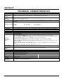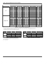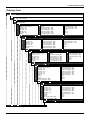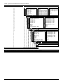
1
T T 3 8 3 M E smar www.smar.com Specifications and information are subject to change without notice. Up-to-date address information is available on our website. web: www.smar.com/contactus.asp Introduction INTRODUCTION The TT383 is a transmitter mainly intended for measurement of temperature by using RTDs or thermocouples, but it can also accept other sensors with resistance or mV output such as pyrometers, load cells, resistance position indicators, etc. The digital technology used in the TT383 enables a single model to accept several types of sensors, an easy interface between the field and the control room and several others features that considerably reduces the installation, operation and maintenance costs. The TT383 is part of Smar's 303 line of Profibus-PA devices. Some of the advantages of bidirectional digital communications are known from existing smart transmitter protocols: Higher accuracy, multi-variable access, remote configuration and diagnostics, and multi-dropping of several devices on a single pair of wires. The digital technology used in the TT383 enables the choice of several types of transfer functions, an easy interface between the field and the control room and several interesting features that considerably reduce the installation, operation and maintenance costs. The system controls variable sampling, algorithm execution and communication so as to optimize the usage of the network, not losing time. Thus, high closed loop performance is achieved. Using Profibus technology, with its capability to interconnect several devices, very large control schemes can be constructed. The TT383, like the 303 family, has Function Blocks built in, like Analog Input and Transducer. It makes a user-friendly equipment configuration. The need for implementation of Fieldbus in small of large systems was considered when developing the entire 303 line of Profibus-PA devices. Now, thanks to Fieldbus, the transmitter accepts eight channels, i.e., eight measurements. This reduces the cost per channel. Other function blocks are also available. They allow flexibility in control strategy implementation. Get the best result of the TT383 by reading carefully these instructions. WARNING In case of using Simatic PDM as the configuration and parameterization tool, Smar recommends that the user does not apply the option "Download to Device". This function can improperly configure the field device. Smar recommends that user make the use of the option "Download to PG / PC" and then selecting the Device Menu, use the menus of the transducer, function and display blocks acting specifically, according to each menu and method for reading and writing. III TT383 – Operation and Maintenance Instruction Manual WARNING This Manual is compatible with version 3.XX, where 3 note software version and XX note software release. The indication 3.XX means that this manual is compatible with any release of software version 3. Waiver of responsibility The contents of this manual abides by the hardware and software used on the current equipment version. Eventually there may occur divergencies between this manual and the equipment. The information from this document are periodically reviewed and the necessary or identified corrections will be included in the following editions. Suggestions for their improvement are welcome. Warning For more objectivity and clarity, this manual does not contain all the detailed information on the product and, in addition, it does not cover every possible mounting, operation or maintenance cases. Before installing and utilizing the equipment, check if the model of the acquired equipment complies with the technical requirements for the application. This checking is the user’s responsibility. If the user needs more information, or on the event of specific problems not specified or treated in this manual, the information should be sought from Smar. Furthermore, the user recognizes that the contents of this manual by no means modify past or present agreements, confirmation or judicial relationship, in whole or in part. All of Smar’s obligation result from the purchasing agreement signed between the parties, which includes the complete and sole valid warranty term. Contractual clauses related to the warranty are not limited nor extended by virtue of the technical information contained in this manual. Only qualified personnel are allowed to participate in the activities of mounting, electrical connection, startup and maintenance of the equipment. Qualified personnel are understood to be the persons familiar with the mounting, electrical connection, startup and operation of the equipment or other similar apparatus that are technically fit for their work. Smar provides specific training to instruct and qualify such professionals. However, each country must comply with the local safety procedures, legal provisions and regulations for the mounting and operation of electrical installations, as well as with the laws and regulations on classified areas, such as intrinsic safety, explosion proof, increased safety and instrumented safety systems, among others. The user is responsible for the incorrect or inadequate handling of equipments run with pneumatic or hydraulic pressure or, still, subject to corrosive, aggressive or combustible products, since their utilization may cause severe bodily harm and/or material damages. The field equipment referred to in this manual, when acquired for classified or hazardous areas, has its certification void when having its parts replaced or interchanged without functional and approval tests by Smar or any of Smar authorized dealers, which are the competent companies for certifying that the equipment in its entirety meets the applicable standards and regulations. The same is true when converting the equipment of a communication protocol to another. In this case, it is necessary sending the equipment to Smar or any of its authorized dealer. Moreover, the certificates are different and the user is responsible for their correct use. Always respect the instructions provided in the Manual. Smar is not responsible for any losses and/or damages resulting from the inadequate use of its equipments. It is the user’s responsibility to know and apply the safety practices in his country. IV Table of Contents TABLE OF CONTENTS SECTION 1 - INSTALLATION .................................................................................................. 1.1 GENERAL ......................................................................................................................................................................... 1.1 MOUNTING ...................................................................................................................................................................... 1.1 NETWORK WIRING ......................................................................................................................................................... 1.3 SENSOR WIRING ............................................................................................................................................................ 1.4 TOPOLOGY AND NETWORK CONFIGURATION ........................................................................................................... 1.4 INTRINSIC SAFETY BARRIER ........................................................................................................................................ 1.6 JUMPER CONFIGURATION ............................................................................................................................................ 1.6 POWER SUPPLY ............................................................................................................................................................. 1.6 INSTALLATION IN HAZARDOUS AREAS ....................................................................................................................... 1.7 INTRINSICALLY SAFE ..................................................................................................................................................... 1.7 SECTION 2 - OPERATION ....................................................................................................... 2.1 FUNCTIONAL DESCRIPTION - HARDWARE ................................................................................................................. 2.1 TEMPERATURE SENSORS ............................................................................................................................................ 2.2 SECTION 3 - CONFIGURATION .............................................................................................. 3.1 TRANSDUCER BLOCK .................................................................................................................................................... 3.1 HOW TO CONFIGURE A TRANSDUCER BLOCK .......................................................................................................... 3.1 FUNCTIONAL DIAGRAM OF THE TEMPERATURE TRANSDUCER BLOCK ................................................................ 3.2 TEMPERATURE TRANSDUCER BLOCK GENERAL PARAMETER DESCRIPTION ..................................................... 3.2 TEMPERATURE TRANSDUCER BLOCK GENERAL PARAMETER ATTRIBUTES ....................................................... 3.5 TT383 - CYCLIC CONFIGURATION ................................................................................................................................ 3.6 TRANDUCER CHANNEL ............................................................................................................................................... 3.10 JUMPER CONFIGURATION .......................................................................................................................................... 3.10 HOW TO CONNECT EIGHT SENSORS ........................................................................................................................ 3.10 COMPENSATION OF COLD JUNCTION ....................................................................................................................... 3.11 CALIBRATION IN TT383 BY THE USER ....................................................................................................................... 3.11 HOW TO CONFIGURE THE ANALOG INPUT BLOCK .................................................................................................. 3.13 SECTION 4 - MAINTENANCE PROCEDURES ........................................................................ 4.1 GENERAL ......................................................................................................................................................................... 4.1 DISASSEMBLY PROCEDURE ......................................................................................................................................... 4.1 SENSOR .......................................................................................................................................................................................... 4.1 ELECTRONIC CIRCUITS ................................................................................................................................................................. 4.2 REASSEMBLE PROCEDURE .......................................................................................................................................... 4.2 INTERCHANGEABILITY .................................................................................................................................................. 4.2 RETURNING MATERIALS ............................................................................................................................................... 4.2 SECTION 5 - TECHNICAL CHARACTERISTIC ....................................................................... 5.1 ORDERING CODE ........................................................................................................................................................... 5.3 APPENDIX A – SRF – SERVICE REQUEST FORM .............................................................. A.1 APPENDIX B – SMAR WARRANTY CERTIFICATE .............................................................. B.1 V TT383 – Operation and Maintenance Instruction Manual VI Installation Flowchart Installation Flowchart Start Was the transmitter configured on the bench to match the application? Yes No Configure the sensor and its connections (Section 1 and Section 3 - Configuration) Check the area classification and its practices. Configure the measuring type (differantial, dual, backup, or single) Install the transmitter preferably on weather- protected areas. Configure the range and unit (AI block) Configure the Damping (AI block) (Section 3 - Configuration) Install the transmitter (mechanically and electrically) according to the application after checking the best position. (Section 1 - Installation) Simule the mV or Ohm value(s) of the work range in the sensor(s) conection terminal(s) Is the reading correct? Yes No See manual (Section 4 - Maintenance) Power the transmitter properly. OK VII TT383 – Operation and Maintenance Instruction Manual VIII Section 1 INSTALLATION General The overall accuracy of temperature and other parameters depends on several variables. Even considering the TT383 excellent performance, a proper installation is essential in order to maximize it. Among all factors which may affect transmitter accuracy, environmental conditions are the most difficult to control. There are, however, several ways of reducing the effects of temperature, humidity and vibration. Locating the transmitter in areas protected from extreme environmental changes can minimize temperature fluctuation effects. The electronic circuit is protected by a humidity proof coating, but frequent exposure to humidity may affect the protection provided. Connecting the sensor as close to the transmitter as possible and using proper wires (See Section 2 - Operation) decreases the measurement error. Mounting This transmitter was designed to be lightweight and robust at the same time. TT383 is easy to be assembled, and its position and dimensions are shown in Figures 1.1 and 1.2, respectively. Use the DIN EN 60715 rail (to replace the DIN EN 50022 standard), as shown on Figure 1.1. Figure 1.1 – Mechanical Assembly 1.1 TT383 – Operation and Maintenance Instruction Manual Figure 1.2 – Dimensional Drawing Mounting: Attach the top rail and press to lock the module. See Figure 1.3. Figure 1.3 – TT383 Assembly in DIN Rail To remove the TT383 from the rack, press the TT383 upwards with its upper part bent outside the rack. See Figure 1.4. 1.2 Installation Figure 1.4 –TT383 Disassembling the DIN Rail Network Wiring Connections are made via the screws on the front of the equipment. Figure 1.5 – Sensors and Supply Connections The wiring block has screws that can receive fork type terminals. WARNING Do not connect the Fieldbus network wires to the sensor terminals (Terminals 1, 2 and 3). TT383 uses the 31.25-kbit/s voltage mode option for the physical signaling. All other devices on the same bus must use the same signaling. All devices are connected in parallel along the same pair of wires. Various types of Fieldbus devices may be connected on the same bus. TT383 is powered via the bus. The limit for such devices is according to the DP/PA coupler limitations for one bus for non-intrinsically safe requirement. In hazardous areas, the number of devices may be limited with intrinsically safe restrictions, according to the DP/PA coupler and barriers limitations. TT383 is protected against reverse polarity, and it can withstand ±35 Vdc without damage, but it will not operate when in reverse polarity. 1.3 TT383 – Operation and Maintenance Instruction Manual Use of twisted pair cables is recommended. It is also recommended to ground shield of shielded cables at one end only. The non-grounded end must be carefully isolated. NOTE Please refer to the Profibus General Manual for more details. Sensor Wiring TT383 accepts one sensor for each channel. In accordance with connection and sensor types, the terminal blocks shall be wired as shown on the Figure 1.5. NOTE All sensors must be isolated of the process. Figure 1.6 – Sensor Wiring Topology and Network Configuration The TT383 may be installed both on bus topology (See Figure 1.7) and tree topology (Figure 1.8). Both types have bus cable with two ends. The equipment is connected to the bus by spurs, which may be integrated to the equipment and results in a lengthy equal to zero. When the length is different from zero, it may be connected to the same equipment spur, depending on its value. In addition, active couplers may extend the spur and bus lengths, or active repeaters can do it with the bus length only. The total cable length, including spurs, between any two devices in the Fieldbus shall not exceed 1900 m. The connection of couplers must be kept in less than 15 per 250 m. In following figures the DP/PA link depends on the application needs. 1.4 Installation SPUR JUNCTION BOX SHIELD + + - - TERMINATOR SPUR SPUR Analog Ground Figure 1.7 – Bus Topology TERMINATOR COUPLER + + - - JUNCTION BOX TERMINATOR Analog Ground Figure 1.8 – Tree Topology 1.5 TT383 – Operation and Maintenance Instruction Manual Intrinsic Safety Barrier When the Fieldbus is in an area requiring intrinsic safety, a barrier must be inserted on the trunk between the power supply and the DP/PA coupler, when it is Non-Ex type. The use of DF47 is recommended. Learn more in http://www.smar.com/products/df47-12.asp. Jumper Configuration In order to work properly, the jumpers J1 and W1 located in the TT383 main board must be correctly configured (See Table 1.1). J1 This jumper enables the simulation mode parameter in the AI block. Table 1.1 - Description of the Jumpers Power Supply The TT383 receives power from the bus via the signal wiring. The power supply may come from a separate unit or from another device such as a controller or DCS. The voltage should be between 9 to 32 Vdc for non-intrinsic safe applications. A special requirement applies to the power supply used in an intrinsically safe bus and depends on the type of barrier used. Use of PS302 is recommended http://www.smar.com/products/ps302p.asp. 1.6 as power supply. Learn more in Installation Installation in Hazardous Areas WARNING Explosions could result in death or serious injury, besides financial damage. Installation of this transmitter in explosive areas must be carried out in accordance with the local standards and the protection type adopted .Before continuing the installation make sure the certificate parameters are in accordance with the classified area where the equipment will be installed. The instrument modification or parts replacement supplied by other than authorized representative of Smar is prohibited and will void the certification. The transmitters are marked with options of the protection type. The certification is valid only when the protection type is indicated by the user. Once a particular type of protection is selected, any other type of protection can not be used. Intrinsically Safe WARNING In hazardous zones with intrinsically safe or non-incendive requirements, the circuit entity parameters and applicable installation procedures must be observed. To protect the application the transmitter must be connected to a barrier. Match the parameters between barrier and the equipment (Consider the cable parameters). Associated apparatus ground bus shall be insulated from panels and mounting enclosures. Shield is optional. If used, be sure to insulate the end not grounded. Cable capacitance and inductance plus Ci and Li must be smaller than Co and Lo of the associated Apparatus. It is not recommended to remove the transmitter cover when the power is ON. 1.7 TT383 – Operation and Maintenance Instruction Manual 1.8 Section 2 OPERATION The TT383 accepts signals from mV generators, such as thermocouples, or resistive sensors, as RTDs. To make this possible, the signal must be within the configured input range. For mV, the range is from -50 to 500 mV, and for resistance, from 0 to 2000 Ohms. Functional Description - Hardware The function of each block is described below. Figure 2.1 - TT383 Block Diagram MUX Multiplexer The MUX multiplexes the sensor terminals to the signal conditioning section ensuring that the voltages are measured between the correct terminals. Signal Conditioner Its function is to apply the correct gain to the input signals to make them suit the A/D - converter. A/D Converter The A/D converts the input signal to a digital format for the CPU. Signal Isolation Its function is to isolate the control and data signal between the input and the CPU. (CPU) Central Processing Unit, RAM, PROM and EEPROM The CPU is the intelligent portion of the transmitter, being responsible for the management and operation of measurement, block execution, self-diagnostics and communication. The program is stored in a PROM. For temporary storage of data there is a RAM. The data in the RAM is lost if the power is switched off. However there is a nonvolatile EEPROM where data that must be retained is stored. Examples, of such data are trim, calibration, block configuration and identification data. Communication Controller It monitors line activity, modulates and demodulates communication signals and inserts and deletes start and end delimiters. 2.1 TT383 – Operation and Maintenance Instruction Manual Power Supply Takes power of the loop-line to power the transmitter circuitry. Power Isolation Just like the signals to and from the input section, the power to the input section must be isolated. Isolation is achieved by converting the DC supply into a high frequency AC supply and galvanically separating it using a transformer. Temperature Sensors Some basic concepts about temperature sensors are presented below. Thermocouples Thermocouples are constructed with two wires made from different metals or alloys joined at one end, called measuring junction or "hot junction". The measuring junction should be placed at the point of measurement. The other end of the thermocouple is open and connected to the temperature transmitter. This point is called reference junction or cold junction. For most applications, the Seebeck effect is sufficient to explain thermocouple behavior as following: How the Thermocouple Works (Seebeck Effect) When there is a temperature difference along a metal wire, a small electric potential, unique to every alloy, will occur. This phenomenon is called Seebeck effect. When two wires of dissimilar metals are joined at one end, and left open at the other, a temperature difference between the two ends will result in a voltage since the potentials generated by the dissimilar materials are different and do not cancel each other out. Now, two important things must be noted. First: the voltage generated by the thermocouple is proportional to the difference between the measuring-junction and the cold junction temperatures. Therefore the temperature at the reference junction must be added to the temperature derived from the thermocouple output, in order to find the temperature measured. This is called cold junction compensation, and is done automatically by the TT383, which has a temperature sensor at the sensor terminals for this purpose. Secondly, if the thermocouple wires are not used, all the way to the terminals of the transmitter (e.g., copper wire is used from sensor-head or marshaling box) will form new junctions with additional Seebeck effects. It will be created and ruin the measurement in most cases, since the cold-junction compensation will be done at the wrong point. NOTE Use thermocouple wires or appropriate extension wires all the way from sensor to transmitter. The relation between the measuring junction temperature and the generated millivoltage is tabulated in thermocouple calibration tables for standardized thermocouple types, the reference temperature being 0 °C. Standardized thermocouples that are commercially used, whose tables are stored in the memory of the TT383, are the following: NBS (B, E, J, K, N, R, S & T) DIN (L & U) Resistive Temperature Detectors (RTDs) Resistance Temperature Detectors, most commonly known as RTD’s, are based on the principle that the resistance of metal increases as its temperature increases. Standardized RTDs, whose tables are stored in the memory of the TT383, are the following: JIS [1604-81] (Pt50 & Pt100) IEC, DIN, JIS [1604-89] (Pt50, Pt100 & Pt500) GE (Cu10) DIN (Ni120) For correct measurement of RTD temperature, it is necessary to eliminate the effect of the resistance of the wires connecting the sensor to the measuring circuit. In some industrial applications, these wires may be hundreds of meters long. This is particularly important at locations where the ambient temperature changes constantly. 2.2 Operation The TT383 allows a 2-wire connection that may cause measuring errors, depending on the length of connection wires and on the temperature to which they are exposed. (see Figure 2.3). In a 2-wire connection, the voltage V2 is proportional to the RTD resistance plus the resistance of the wires. V2 = [RTD + 2 x R] x I TRANSMITTER R 2,1 V2 I RTD R 3,4 Figure 2.3 - 2-Wire Connection In order to avoid the resistance effect of the connection wires, it is recommended to use a 3-wire connection (see Figure 2.4) or a 4-wire connection (see Figure 2.5). In a 3-wire connection, terminal 3 is a high impedance input. Thus, no current flows through that wire and no voltage drop is caused. The voltage V2-V1 is independent of the wire resistances since they will be cancelled, and is directly proportional to the RTD resistance alone. V2-V1 = [RTD + R] x I - R x I = RTD x I TRANSMITTER 2,1 R V2 I RTD 3 4 V1 R Figure 2.4 – 3-Wire Connection 2.3 TT383 – Operation and Maintenance Instruction Manual 2.4 Section 3 CONFIGURATION This section describes the TT383 blocks. They follow the Profibus PA specifications, but concerning the transducer blocks, the input transducer block and display, they have some special features. The 303 Smar family is integrated in Profibus View, from Smar and in the Simatic PDM, from Siemens. It is possible to integrate any Smar device in Profibus with any configuration tool for Profibus PA devices. It is necessary to provide a Device Description or Drive according to the configuration tool. In this manual it is possible to find some examples using Profibus View or Simatic PDM. In order to assure correct values in the offline configuration, first run “Download to PG/PC” option to assure valid values. After, run the Menu Device option to configure the required parameters using the related menus. NOTE In offline configuration, it is not recommendable to use the “Download to Device” option. This function can misconfigure the equipment. Transducer Block Transducer block insulates function blocks from the specific I/O hardware, such as sensors, actuators. Transducer block controls access to I/O through manufacturer specific implementation. This allows the transducer block to execute as frequently as necessary to obtain good data from sensors without burdening the function blocks that uses the data. It also insulates the function block from the manufacturer specific characteristics of certain hardware. By accessing the hardware, the transducer block can get data from I/O or passing control data to it. The connection between Transducer block and Function block is called channel. These blocks can exchange data from its interface. Normally, transducer blocks perform functions, such as linearization, characterization, temperature compensation, control and exchange data to hardware. How to Configure a Transducer Block The transducer block has an algorithm which is a set of contained parameters. It means that it is no possible to link these parameters to other blocks and publish this link via communication and a channel connecting it to a function block. The algorithm describes the behavior of the transducer as a data transfer function between the I/O hardware and other function block. The transducer parameter cannot be linked in input and output of others blocks. The transducer parameters can be divided in manufacturers’ standard and specific parameters. The standard parameters will be present for such class of device, as pressure, temperature, actuator, etc., whatever is the manufacturer. Oppositely, the manufacturers specific ones are defined only for its manufacturer. As common manufacturer specific parameters, we have calibration settings, material information, linearization curve, etc. When you perform a standard routine such as calibration, you are guided step by step by a method. The method is generally defined as guideline to help the user to make common tasks. The Configuration Tool identifies each method associated to the parameters and enables the interface to it. 3.1 TT383 – Operation and Maintenance Instruction Manual Functional Diagram of the Temperature Transducer Block Process Transducer Block R.J. Transducer Block 0 1 RJ_TEMP 2 AI FB(’s) EXTERNAL_RJ_VALUE RJ_TYPE R.J. Comp. Arithmetic LIN Input Linearization BIAS_1 SECONDARY_VALUE_1 + Input 1 T1 + LIN PRIMARY_VALUE + Input 2 T2 + LIN SECONDARY_VALUE_2 BIAS_2 INPUT_RANGE, SENSOR_CONNECTION, COMP_WIRE1/2 LIN_TYPE, TAB_... SENSOR_MEAS_TYPE Figure 3.1 – Functional Diagram of the Temperature Block Temperature Transducer Block General Parameter Description Temperature Transducer Block General Parameter Description formatted: font: Not Bold, English (U.S.) PARAMETER BIAS_1 BIAS_2 DESCRIPTION Bias that can be algebraically added to process value of channel 1. The unit of BIAS_1 is the PRIMARY_VALUE_UNIT. Bias that can be algebraically added to process value of channel 2. The unit of BIAS_2 is the PRIMARY_VALUE_UNIT. Input malfunction: Diagnosis object for errors that concerns all values 0 = device OK Bit: 0= 1= 2–4= 5–7= INPUT_FAULT_GEN Rj error Hardware error reserved manufacturer specific Byte: 0x00: status ok; 0x80: hardware failure Input malfunction: Diagnosis object for errors that concern SV_1 0 = Input OK Bit: INPUT_FAULT_1 0= 1= 2= 3= 4–5= 6–7= Byte: 0x00: input ok; 0x80: sensor failure 3.2 underrange overrange lead breakage short circuit reserved manufacturer specific Configuration PARAMETER DESCRIPTION Input malfunction: Diagnosis object for errors that concern SV_2 INPUT_FAULT_2 0 = below range 1 = over the range 2 = lead breakage 3 = short circuit 4 – 5 = reserved 6 – 7 = manufacturer specific Byte: 0x00 = input OK 0x80 = hardware failure Electrical input range and mode. The ranges are manufacturer specific but range n is smaller than range n+1 if more than one range is supported for one input mode (e.g. range1=0...400Ω, range2=0...4kΩ). INPUT_RANGE is equal for channel 1 and 2. INPUT_RANGE Defined codes (other codes are reserved): 0 = mV range 1 => mV22 1 = mV range 2 => mV100 : 9 = mV range 10 128 = Ω range 129 = Ω range 2 : 137 = Ω range 10 192 = mA range 1 193 = mA range 2 : 201 = mA range 10 240 = manufacturer specific : 249 = manufacturer specific 250 = not used 251 = none 252 = unknown 253 = special Remark: When using codes 240..249 (manufacturer specific) interchangeability is not possible. Select the type of sensor (Code) for Thermocouples, Rtd, Pyrometers or linear. LIN_TYPE 101 = RTD Pt50 a=0.003850 (IEC 751, DIN 43760, JIS C1604-97, BS1904) 102 = RTD Pt100 a=0.003850 (IEC 751, DIN 43760, JIS C1604-97, BS1904) 104 = RTD Pt500 a=0.003850 (IEC 751, DIN 43760, JIS C1604-97, BS1904) 107 = RTD Pt50 a=0.003916 (JIS C1604-81) 108 = RTD Pt100 a=0.003916 (JIS C1604-81) 120 = RTD Ni120 a=0.006720 (Edison curve #7) 128 = TC Type B, Pt30Rh-Pt6Rh (IEC 584, NIST 175, DIN 43710, BS 4937, ANSI MC96.1, JIS C1602, NF C42-321) 131 = TC Type E, Ni10Cr-Cu45Ni (IEC584, NIST 175, DIN 43710, BS 4937, ANSI MC96.1, JIS C1602, NF C42-321) 133 = TC Type J, Fe-Cu45Ni (IEC 584, NIST 175, DIN 43710, BS 4937, ANSI MC96.1, JIS C1602, NF C42321) 134 = TC Type K, Ni10Cr-Ni5 (IEC 584, NIST 175, DIN 43710, BS 4937, ANSI MC96.1, JIS C1602, NF C42321) 135 = TC Type N, Ni14CrSi-NiSi (IEC 584, NIST 175, DIN 43710, BS 4937, ANSI MC96.1, JIS C1602, NF C42-321) 136 = TC Type R, Pt13Rh-Pt (IEC 584, NIST 175, DIN 43710, BS 4937, ANSI MC96.1, JIS C1602, NF C42321) 137 = TC Type S, Pt10Rh-Pt (IEC 584, NIST 175, DIN 43710, BS 4937, ANSI MC96.1, JIS C1602, NF C42321) 138 = TC Type T, Cu-Cu45Ni (IEC 584, NIST 175, DIN 43710, BS 4937, ANSI MC96.1, JIS C1602, NF C42321) 139 = TC Type L, Fe-CuNi (DIN 43710) 140 = TC Type U, Cu-CuNi (DIN 43710) 145 to 239 reserved Manufacturer specific: 240 Cu10 GE, Edison #15 241 Ohm 100 242 Ohm 400 243 Ohm 2000 244 mV22 245 mV100 246 mV500 247 a 253 reserved 3.3 TT383 – Operation and Maintenance Instruction Manual PARAMETER LOWER_SENSOR_LIMIT UPPER_SENSOR_LIMIT PRIMARY_VALUE PRIMARY_VALUE_UNIT SECONDARY_VALUE_1 (SV_1) SECONDARY_VALUE_2 (SV_2) SENSOR_MEAS_TYPE SENSOR_CONNECTION PRIMARY_VALUE_RANGE CAL_POINT_HI CAL_POINT_LO CAL_MIN_SPAN SENSOR_SERIAL_NUMBER RJ_TEMP EXTERNAL_RJ_VALUE RJ_TYPE TRANSDUCER_NUMBER FACTORY_DIGITAL_INPUTS FACTORY_GAIN_REFERENCE BACKUP_RESTORE EEPROM_FLAG MAIN_BOARD_SN ORDERING_CODE DESCRIPTION Physical lower limit function of sensor (e.g. Pt 100 = -200°C) and input range. In the case of multichannel measurements (e.g. differential measurement) the meaning of LOWER_SENSOR_LIMIT is the limit of one channel not the calculated limit of both channels. The unit of LOWER_SENSOR_LIMIT is the PRIMARY_VALUE_UNIT. Physical upper limit function of sensor (e.g. Pt 100 = 850°C) and input range. In the case of multichannel measurements (e.g. differential measurement) the meaning of UPPER_SENSOR_LIMIT is the limit of one channel not the calculated limit of both channels. The unit of UPPER_SENSOR_LIMIT is the PRIMARY_VALUE_UNIT. Process value, function of SECONDARY_VALUE_1/2. The unit of PRIMARY_VALUE is the PRIMARY_VALUE_UNIT. Show the unit code of the PRIMARY_VALUE and other values. The unit is select using PRIMARY_VALUE_RANGE parameter. Set of unit codes: 1000: K (Kelvin) 1001: °C (degree Celsius) 1002: °F (degree Fahrenheit) 1003: Rk (Rankine) (Ohm) 1281: Ω 1243: mV (milivolt) Process value connected to the channel 1 corrected by BIAS_1. The unit of SECONDARY_VALUE_1 is the PRIMARY_VALUE_UNIT. Process value connected to the channel 2 corrected by BIAS_2. The unit of SECONDARY_VALUE_2 is the PRIMARY_VALUE_UNIT. Mathematical function to calculate PRIMARY_VALUE (PV). Defined codes: 128: PV = SV_1 - SV_2 Difference manufacturer specific: 220: = Backup 230: = Process Temperature Connection to the sensor, select for 2 and 3 wires connection. Defined codes: 0 = 2 wires 1 = 3 wires The high and low range limits values, the engineering units and the number of digits to the right of the decimal to be used to display the primary value. This parameter contains the highest calibrated value. For calibration of the high limit point you give the high measurement value (temperature) to the sensor and transfer this point as HIGH to the transmitter. Unit derives from CAL_UNIT. This parameter contains the lowest calibrated value. For calibration of the low limit point you give the low measurement value (temperature) to the sensor and transfer this point as LOW to the transmitter. Unit derives from CAL_UNIT. This parameter contains the minimum calibration span value allowed. This minimum span information is necessary to ensure that when calibration is done, the two calibrated points (high and low) are not too close together. Unit derives from CAL_UNIT. The sensor serial number. Referring to the junction temperature. The RJ_TEMP unit ise PRIMARY_VALUE_UNIT. If PRIMARY_VALUE_UNIT is not temperature unit (e.g. mV) RJ_TEMP is in °C. Fixed temperature value of na external reference junction. The EXTERNAL_RJ_VALUE unit is PRIMARY_VALUE_UNIT. If PRIMARY_VALUE_UNIT is not temperature unit (e.g. mV) EXTERNAL_RJ_VALUE is in °C. Select a fixed internal reference junction. Codes defined: 0 = Without reference: Compensation is not used (for example, for TC Type B). 1 = Internal: the reference junction temperature is measured by the equipment via a sensor mounted internally or externally.. 2 = External: The EXTERNAL_RJ_VALUE fix value is used for compensation. The reference junction is kept at a constant temperature (for example, via thermostat tf the reference junction). Select the transducer 1,2 or 8. Read the digital inputs. Calibration point for sensors Ohm and mV. This parameters allow to record and recover the data according to the factory procedures and user calibration. It has the following options: 1, " Factory Cal Restore ", 2, " Last Cal Restore ", 3, " Default Data Restore ", 11, “Factory Cal Backup ", 12, " Last Cal Backup ", 0, none ". This parameter is used to indicate that something was save in EEPROM memory. Serial number of the motherboard. Indicates information about the equipment manufacturer. Table 3.1 - Parameter Description 3.4 Configuration Temperature Transducer Block General Parameter Attributes Param. Usage/ Object Relative Index Parameter Name type Data type Store Size Access Type of Default Value Mandatory Download Order Optional Transport (Class) M View ... Standard Parameter see General Requirements General Parameter for Temperature Transducer Block 8 PRIMARY_VALUE simple DS-33 D 5 r C/a 9 PRIMARY_VALUE_UNIT simple Unsigned 16 S 2 r,w C/a 10 SECONDARY_VALUE_1 simple DS-33 D 5 r C/a M 11 SECONDARY_VALUE_2 simple DS-33 D 5 r C/a O 12 SENSOR_MEAS_TYPE simple unsigned 8 S 1 r,w C/a 3 M 13 INPUT_RANGE simple unsigned 8 S 1 r,w C/a 4 M 14 LIN_TYPE 1 M 19 BIAS_1 simple Float S 4 r,w C/a 0.0 5 M 20 BIAS_2 simple Float S 4 r,w C/a 0.0 21 UPPER_SENSOR_LIMIT simple Float N 4 r C/a 22 LOWER_SENSOR_LIMIT simple Float N 4 r C/a M 24 INPUT_FAULT_GEN simple unsigned 8 D 1 r C/a M 1 25 INPUT_FAULT_1 simple unsigned 8 D 1 r C/a M 1 26 INPUT_FAULT_2 simple unsigned 8 D 1 r C/a O 27-35 2 1 See General Requirements. M O M Not used 36 SENSOR_CONNECTION simple unsigned 8 S 1 r,w C/a 37 COMP_WIRE1 simple Float S 4 r,w C/a 0.0 38 COMP_WIRE2 simple Float S 4 r,w C/a 0.0 7 M 8 M O 39 – 61 Not used 62 PRIMARY_VALUE_RANGE record DS-36 S 11 r,w C/a 63 CAL_POINT_HI simple Float S 4 r,w C/a 850.0 64 CAL_POINT_LO simple Float S 4 r,w C/a -200.0 65 CAL_MIN_SPAN simple Float S 4 r C/a 10.0 66 CAL_UNIT simple Unsigned 16 S 2 r,w C/a 1001 67 SENSOR_RANGE record DS-36 N 11 r C/a 68 SENSOR_SN simple Unsigned 32 S 4 r,w C/a 69 SECONDARY_VALUE simple DS-33 D 5 r C/a 70 SECONDARY_VALUE_UNIT simple Unsigned 16 S 2 r,w C/a 71 MODULE_SN simple Unsigned 32 S 4 r,w C/a 72 SECONDARY_VALUE_ ACTION simple Unsigned 8 S 1 r,w C/a 73 TWO_WIRES_COMPENSA-TION simple Unsigned 8 S 1 r,w C/a 74 SENSOR_TRANSDUCER_ NUMBER simple Unsigned 8 S 1 r,w C/a 75 FACTORY_DIGITAL_INPUTS simple Float N 4 r,w C/a 76 FACTORY_GAIN_ REFERENCE simple Unsigned 8 S 1 r,w C/a 77 FACTORY_BORNE_ REFERENCE simple Unsigned 8 S 1 r,w C/a 78 BACKUP_RESTORE simple Unsigned 8 S 1 r,w C/a 79 XD_ERROR simple Unsigned 8 D 1 r C/a 80 MAIN_BOARD_SN simple Unsigned 32 S 4 r,w C/a 81 EEPROM_FLAG simple Unsigned 8 D 1 r C/a 82 ORDERING_CODE simple Unsigned 8 S 50 r,w C/a 1001 Table 3.2 - General Parameter for Temperature Transducer Block 3.5 TT383 – Operation and Maintenance Instruction Manual TT383 - Cyclic Configuration The PROFIBUS-DP and PROFIBUS-PA protocols have protections against communication failures between the slave device and the network master. For example, during initialization, these protections are used to check possible errors. After powering up the field device (slave), it is possible to cyclically exchange information with the class 1 master, if the parameterization for the slave is correct. This information is obtained using the GSD files (supplied by the device manufacturer and containing their descriptions). Through the commands below, the master executes all initialization process with the PROFIBUS-PA device: • Get_Cfg: uploads the slave configuration on the master and checks network configuration; • Set_Prm: writes to the slave parameters and executes the parameterization network; • Set_Cfg: configures the slaves according to its outputs and inputs; • Get_Cfg: another command, where the master checks the slave configuration. All these services are based on the information obtained from slave gsd files. The GSD file from TT383 shows details such as hardware and software revision, device bus timing and information about cyclic data exchange. TT383 has 1 functional block: AI. Most PROFIBUS configuration tools use two directories where the different manufacturers’ GSD’s and BITMAPS files are stored. The GSD’s and BITMAPS for Smar devices can be obtained through the website: (https://www.smar.com), on the “download” link. The following example shows the necessary steps to integrate the TT383 on a Profibus system. These steps are valid for the entire 303 line of Smar devices: • Copy the TT383 gsd file to the research directory of the PROFIBUS configuration tool, usually called GSD; • Copy the TT383 bitmap file to the research directory of the PROFIBUS configuration tool usually called BMP; • After choosing the master, define the baud rate for the network. Do not forget that couplers may work with the following baud rate: 45.45 kbits/s (Siemens model), 93.75 kbits/s (P+F model) and 12 Mbits/s (P+F, SK2 model). The IM157 device link (Siemens model) may work up to 12 Mbits/s; • Add the TT383 and specify its physical bus address; • Choose the cyclic configuration via parameterization using the gsd file that depends on the application, as detailed previously. For every AI (Analog Input) block, the TT383 provides the process variable to the master in 5 bytes value, being the first four according to float point data type and the fifth byte is the status that brings the measure quality of this information; • It allows activating the condition of watchdog, which the device goes to a fail safe condition, when a loss of communication is detected with the master. Configuration softwares like Profibus View from Smar or Simatic PDM (Process Device Manager) from Siemens can configure many parameters of the Input Transducer block. See the figures 3.2 and 3.3. 3.6 Configuration The device was created as TT383. Here, you can see all blocks instantiated. As you can see the Transducer and Display are treated as special type of Function Blocks, called Transducer Blocks. Figure 3.2 – Profibus View – Function and Transducers Block Figure 3.3 – PDM Simatic - Function and Transducers Blocks 3.7 TT383 – Operation and Maintenance Instruction Manual Use this menu: - To change the device address; - To make the up/download of parameters; - To configure the Transducer Blocks, Analog Blocks and Display Block; - To calibrate the transmitter; - To make the reset by software, to protect the device against writing and to simulate the value from transducer block to analog block; - To save and restore data calibration. To make the configuration of Transducer Block, we need to select the Transducer 1 block on the main menu. The user can select the Measured type: T1-T2, Process Temperature or Backup. The user can set the sensor transducer number. Please, select sensor type according to the application and the connection type. This parameter selects the type of sensor connection. The options here will depend on Sensor Type chosen as described above. 3.8 Figure 3.4 - Profibus View - Transducer Basic Settings After selecting the desired option, this key should be pressed. Configuration Figure 3.5 – Profibus View - Transducer Advanced Settings The user can configure the Transducer Block, according to the selected Measurement Type (when you have selected "Process Temperature", it means that you will have eight sensors, eight transducer blocks and eight analog input blocks). Please, select the parameters according to your application. It is possible to configure connection and sensor type by means of parameters SENSOR_TYPE and SENSOR_CONNECTION. The connection and sensor types available are listed in the tables Table 3.6 and Table 3.7. Using the "Advanced Settings" window, the user can set the scaling and unit for the output value according to the Transducer Block Diagram, bias of channels and set the cold junction and 2-wires compensation according to his application. Figure 3.6 – PDM Simatic - Offline Configuration - Transducer Advanced Settings 3.9 TT383 – Operation and Maintenance Instruction Manual Setting the TT383 Address The address configuration can be done in two ways. The first is via configurator and the second via hardware. The key for address configuration is located under the cover and on the front side of the equipment identification label. Possible addressing is from 3 (000.0011) to 126 (0111.1111). The key has eight positions. Each position represents one bit in binary notation. The number one in the key is the zero bit consecutively up to number seven, which is bit 6. See Figure 3.7. To set the bit in level one, the key must move to ON. To set the bit in level zero, the key must be in OFF. The position indicated by number eight is used for configuration if the TT383 address must come from the hardware or the software. If the key is in OFF, the address comes from the software, if not, the key comes from the hardware. See on Table 3.3 an example of the TT383 address configuration. Figure 3.7 –Addressing Key Model BITS 7654321 0000011 0000100 ... 1111110 ADDRESS 3 4 ... 126 Table 3.3 – Example of the Address Configuration NOTE After address setup is necessary to perform a reset on the device for which the new address is updated. Transducer Channel The transducer channel associates the sensor to the transducer. Jumper Configuration In order to work properly, the jumpers J1 and J3 located in the TT383 main board must be correctly configured. J1 is responsible to enable the AI block simulate mode. How to Connect Eight Sensors The TT383 is able to operate simultaneously with eight sensors, using eight transducer blocks, if necessary. Configuration types in eight sensors operation are as follows: 3.10 Configuration Differential – Transducer output is the difference between the readout of sensor 1 and the readout of sensor 2 (other channel). Backup - If the first sensor opens, the second sensor (other channel) will supply the signal to the transducer. Process Temperature – The readout is only in one channel. Compensation of Cold Junction Compensation of Cold Junction for thermocouplers is in RJ_Type parameter and it can: 1) 2) 3) be unable in “No reference”, come a sensor installed in the terminal (Internal reference) or come a constant configured by user (External reference). Calibration in TT383 by the User The TT383 is very stable throughout time and do not need additional calibrations besides the factory calibration. However, should the client decide to use his reference to calibrate the TT383 (which is not recommendable), this may be done by means of parameters CAL_POINT_LO and CAL_POINT_HI. When trim is performed, always use two points as reference; never consider only one point as a reference. Using Profibus View or the Simatic PDM, the calibration is done selecting at the main menu "Calibration - Transducer TRD1-Lower/Upper" or menu Calibration Transducer TRD2-Lower/Upper". The user can select lower or upper calibration. The user can see the lower sensor limit and the actual calibrated point. The use just needs to inform the desired point. The user can see the measured temperature and its status. The user can verify the calibration operation result. Figure 3.8 – Profibus View - Lower Calibration Procedures 3.11 TT383 – Operation and Maintenance Instruction Manual Figure 3.9 – PDM Simatic - Lower Calibration Procedure If the user to select the upper page (UPPER): The user can see the upper sensor limit and the actual calibrated point. The use just needs to inform the desired point. The user can verify the calibration operation result. The user can see the measured temperature and its status. Figure 3.10 – Profibus View - Upper Calibration Procedures 3.12 Configuration Figure 3.11 – PDM Simatic - Upper Calibration Procedure NOTE Every time the sensor is changed, TRIM values are reset. How to Configure the Analog Input Block The Analog Input block takes the input data from the Transducer block, selected by channel number, and makes it available to other function blocks at its output. The transducer block provides the input unit of the Analog Input, and when the unit is changed in the transducer, the PV_SCALE unit is changed too. Optionally, a filter may be applied in the process value signal, whose time constant is PV_FTIME. Considering a step change to the input, this is the time in seconds to the PV reaches 63.2% of the final value. If the PV_FTIME value is zero, the filter is disabled. For more details, please, see the Function Blocks Specifications. To configure the Analog Input Block, please, select the Analog Input Block, in the main menu. Select the analog block according to the application. Using this window, the user can configure the block mode operation, selects the channel, scales and unit for input and output value and the damping. The user can set the PV damping value. The user can select PV, Sec Value 1 or Sec Value 2 for the channel. parameter. Scale of input value. The unit comes from the transducer block. Scales and unit for the output value. The user can set the block mode operation. Figure 3.12 – Profibus View - Basic Settings for Analog Input Block 3.13 TT383 – Operation and Maintenance Instruction Manual Figure 3.13 – PDM Simatic - Basic Settings for Analog Input Block Selecting the page "Advanced Settings", the user can configure the conditions for alarms and warnings, as well the fail safe condition. Please, see the window: The user can set Alarm/Warning limits. The fail safe conditions. Figure 3.14 – Profibus View - Advanced Settings for Analog Input Block 3.14 Configuration Figure 3.15 – PDM Simatic - Advanced Settings for Analog Input Block The user can set the mode block operation. The user can monitor the output parameter and verify the current state alarm. Figure 3.16 – Profibus View - Analog Input Block 3.15 TT383 – Operation and Maintenance Instruction Manual Figure 3.17 – PDM Simatic - Online Configuration for Analog Input Block 3.16 Section 4 MAINTENANCE PROCEDURES General SMAR TT383 transmitters are extensively tested and inspected before delivery to the end user. Nevertheless, during their design and development, consideration was given to the possibility of repairs being made by the end user, if necessary. In general, it is recommended that end users do not try to repair printed circuit boards. Spare circuit boards may be ordered from SMAR whenever necessary. SYMPTOM NO COMMUNICATION INCORRECT READING INCORRECT READING PROBABLE SOURCE OF PROBLEM Transmitter Connections Check wiring polarity and continuity. Check for shorts or ground loops. Check if the power supply connector is connected to main board. Check if the shield is not used as a conductor. It should be grounded at one end only. Power Supply Check power supply output. The voltage must be between 9 - 32 Vdc at the TT383 terminals. Noise and ripple should be within the following limits: a) 16 mV peak to peak from 7.8 to 39 KHz. b) 2 V peak to peak from 47 to 63 Hz for non-intrinsic safety applications and 0.2 V for intrinsic safety applications. c) 1.6 V peak to peak from 3.9 MHz to 125 MHz. Network Configuration Make sure that device address is configured correctly. Electronic Circuit Failure Check the main board for defect by replacing it with a spare one. Transmitter Connections Check for intermittent short circuits, open circuits and grounding problems. Check if the sensor signal is reaching the TT383 terminal block by measuring it with a multimeter at the transmitter- end. For mV and thermocouples test can be done with connected and disconnected to the transmitter. Noise, Oscillation Adjust damping Check if the sensor is isolated from the process; Check the terminal block for humidity. Check that the shielding of the wires between sensor/transmitter and transmitter/panel is grounded only in one end. Sensor Check the sensor operation; it shall be within its characteristics. Check sensor type; it shall be the type and standard that the TT383 has been configured to. Check if process is within the range of the sensor and the TT383. Electronic Circuit Failure Check the integrity of circuit replacing it with a spare one. Transmitter Configuration Check if the sensor and wires configuration are correct. Table 4.1 - Messages of Errors and Potential Cause Disassembly Procedure Refer to Figure 4.1. Make sure to disconnect the power supply before disassembling the transmitter. Sensor If the sensor is mounted on the transmitter, first disconnect the wires in order to prevent the wires from breaking. 4.1 TT383 - Operation and Maintenance Instruction Manual Electronic Circuits To remove the circuit board assembly (2 and 3) first loosen the screws of the side covers. Then remove the plates of the housing, carefully The main board (2) and input board (3) are married at the factory and should be changed together and should not be mixed each other. WARNING The boards have CMOS components, which may be damaged by electrostatic discharges. Observe correct procedures for handling CMOS components. It is also recommended to store the circuit boards in electrostatic-proof cases. Reassembly Procedure Put input board (3) and the main board (2) into housing (8). Attach the side cover ith four screws; Reconnect the sensors in the terminals. Interchangeability The Main and Input boards must be kept together because of the calibration data that is stored in the main board EEPROM. In the case of one board being faulty, both must be replaced. Returning Materials If it is become necessary to return the transmitter to SMAR, simply contact your local agent or SMAR office, informing the defective instrument’s serial number, and return it to our factory. In order to expedite analysis and solution of the problem, the defective item should be returned with a description of the failure observed, with as many details as possible. Other information concerning the instruments operation, such as service and process conditions are also helpful. 4.2 Maintenance Procedures Figure 4.1 - Exploded View ACCESSORIES ORDERING CODE DESCRIPTION PS302 Power Supply BT302 Terminator DF47 Intrinsic Safety Barrier DF48 Fieldbus Repeater Table 4.2 - Accessories SPARE PARTS LIST DESCRIPTION OF PARTS POSITION CODE Housing 1 400-1187 Main Board 2 400-1188 Input Board 3 400-1189 Table 4.3 – Spare Part List 4.3 TT383 - Operation and Maintenance Instruction Manual 4.4 Section 5 TECHNICAL CHARACTERISTICS Functional Specifications Inputs Output and Communication Protocol Power Supply / Current Consumption See table 1, 2 and 3 Digital only. Complies with IEC 61158-2: 2000 (H1): 31.25 kbit/s voltage mode, bus powered. Bus powered: 9 - 32 Vdc. Quiescent current consumption: 14 mA. Failure Alarm For sensor or circuit failures, status is sent to output parameters. Detailed diagnostics are available in the contained parameters. Temperature Limits Operation: Storage: 0 ºC to 0 ºC to 75 ºC 85 ºC (32 ºF to 167 ºF) (32 ºF to 185 ºF) Turn-on Time Configuration Performs within specifications in less than 12 seconds after power is applied to the transmitter. Remote configuration using Profibus PA protocol, with AMSTM, FieldCareTM, HHT375, Profibus View or Simatic PDM. Humidity Limits 0 to 75 RH Performance Specifications Accuracy See tables 1, 2 and 3 For a 10 ºC variation: mV (- 6 to 22 mV), TC (NBS: B, R, S,T): ± 0.03% of the input milivoltage or 0.002 mV whichever is greater; mV (- 10 to 100 mV), TC (NBS: E, J, K, N; DIN: L, U): ± 0.03% of the input milivoltage or 0.01 mV whichever is greater; mV (-50 to 500 mV): ± 0.03% of the input milivoltage or 0.05 mV whichever is greater; Ambient Temperature Effect Ohms (0 to 100 Ω), RTD (GE: Cu10): ± 0.03% of the input resistance or 0.01 Ω whichever is greater; Ohms (0 to 400 Ω), RTD (DIN: Ni120; IEC: Pt50, Pt100; JIS: Pt50, Pt100): ± 0.03% of the input resistance or 0.04 Ω whichever is greater; Ohms (0 to 2000 Ω), RTD (IEC: Pt500), RTD (IEC: Pt1000): ± 0.03% of the input resistance or 0.2 Ω whichever is greater; TC: cold-junction compensation rejection 60:1 (Reference: 25.0 ± 0.3 °C). Power Supply Effect Electromagnetic Interference Effect ± 0.005% of calibrated span per volt. Approved according to IEC 61000-6-2:1999, IEC 61000-6-4:1997 and IEC 61326:2002. Physical Specifications Housing Terminal Block Weight Mounting Housing Control Functions Characteristics Housing profile are made of Anodized Aluminum. Lateral caps are made of PA 6.6 1 terminal for power supply connection; 8 terminals for sensor connection. 300 g Using DIN rail EM 60715 (previously DIN EN 50022). Protection: IP20 Physical Block, Tranducer and Analog Input. 5.1 TT383 – Operation and Maintenance Instruction Manual 2 e 3 wires SENSOR RANGE °C TYPE MINIMUM SPAN °C RANGE °F °C DIGITAL ACCURACY* Cu10 GE -20 to 250 -4 to 482 50 ± 1.5 Ni120 DIN -50 to 270 -58 to 518 5 ± 0.2 Pt50 IEC -200 to 850 -328 to 1562 10 ± 0.32 Pt100 IEC -200 to 850 -328 to 1562 10 ± 0.3 Pt500 IEC -200 to 450 -328 to 842 10 ± 0.3 Pt1000 IEC -200 to 300 -328 to 572 10 ± 0.3 Pt50 JIS -200 to 600 -328 to 1112 10 ± 0.32 Pt100 JIS -200 to 600 -328 to 1112 10 ± 0.32 B NBS 100 to 1800 212 to 3272 50 ± 1.5* E NBS -100 to 1000 -148 to 1832 20 ± 0.3 J NBS -150 to 750 -238 to 1382 30 ± 0.4 K NBS -200 to 1350 -328 to 2462 60 ± 0.7 N NBS -100 to 1300 -148 to 2372 50 ± 0.6 R NBS 0 to 1750 32 to 3182 40 ± 0.8 S NBS 0 to 1750 32 to 3182 40 ± 1.0 T NBS -200 to 400 -328 to 752 15 ± 0.35 L DIN -200 to 900 -328 to 1652 35 ± 0.4 U DIN -200 to 600 -328 to 1112 50 ± 0.5 RTD THERMOCOUPLE Table 5.1 – 2 or 3 wires Sensor Characteristics * Accuracy of value read on display and accessed by communication. The 4-20 mA accuracy is the digital accuracy ±0.03% ** Not applicable for the first 20% of the range (up to 440 °C). RANGE mV 22 0.40 ± 0.02% or ± 10 µV mV -10 to 100 2.00 ± 0.02% or ± 20 µV -50 to 500 10.00 ± 0.02% or ± 50 µV -28 to 28 0.40 ± 0.10% or ± 20 µV -110 to 110 2.00 ± 0.10% or ± 50 µV -6 to mV DIF. MINIMUM SPAN mV *DIGITAL ACCURACY % SENSOR Table 5.3 - mV Sensor Characteristics * Not applicable for the first 20% of the range (up to 440 °C). NA - Not applicable. 5.2 SENSOR Ohm Ohm DIF. RANGE Ohm MINIMUM SPAN Ohm *DIGITAL ACCURACY % ± 0.02% or ± 0.05 Ohm 0 or 100 1 0 or 400 4 ± 0.02% or ± 0.08 Ohm 0 or 2000 20 ± 0.02% or ± 0.20 Ohm -100 or 100 1 ± 0.08% or ± 0.08 Ohm -400 or 400 4 ± 0.1% or ± 0.20 Ohm Table 5.4 - Ohm Sensor Characteristics Technical Characteristics Ordering Code MOD. EIGHT CHANNELS TEMPERATURE TRANSMITTER TT383 Profibus PA COD Certification Type N Without Certification I Ex-ia (Intrinsic Safe) (Pending) COD Organ Certifier 5 CEPEL (Pending) 6 Without Certification COD. Sensor Type (Sensor 1) 1 9 400 Ohm H Thermocouple type S – NBS RTD Cu10 – GE 2 A 2K Ohm I Thermocouple type T - NBS RTD Ni120 – Edison Curve 7 3 B Thermocouple type B - NBS J Thermocouple type L – DIN RTD Pt50 – IEC 4 C Thermocouple type E – NBS K Thermocouple type U – DIN RTD Pt100 – IEC 5 D Thermocouple type J – NBS L 22 mV RTD Pt500 – IEC 6 E Thermocouple type K - NBS M 100 mV RTD Pt50 – JIS 7 F Thermocouple type N – NBS N 500 mV RTD Pt100 – JIS 8 G Thermocouple type R – NBS 100 Ohm COD. Sensor Connection (Sensor 1) 2 2-wires 3 3-wires COD. Sensor Type (Sensor 2) 1 9 400 Ohm H Thermocouple type S – NBS RTD Cu10 – GE 2 A 2K Ohm I Thermocouple type T - NBS RTD Ni120 – Edison Curve 7 3 B Thermocouple type B - NBS J Thermocouple type L – DIN RTD Pt50 – IEC 4 C Thermocouple type E – NBS K Thermocouple type U – DIN RTD Pt100 – IEC 5 D Thermocouple type J – NBS L 22 mV RTD Pt500 – IEC 6 E Thermocouple type K - NBS M 100 mV RTD Pt50 – JIS 7 F Thermocouple type N – NBS N 500 mV RTD Pt100 – JIS 8 G Thermocouple type R – NBS 100 Ohm COD. Sensor Connection (Sensor 2) 2 3 3-wires 2-wires COD. Sensor Type (Sensor 3) 1 9 400 Ohm H Thermocouple type S – NBS RTD Cu10 – GE 2 A 2K Ohm I Thermocouple type T - NBS RTD Ni120 – Edison Curve 7 3 B Thermocouple type B - NBS J Thermocouple type L – DIN RTD Pt50 – IEC 4 C Thermocouple type E – NBS K Thermocouple type U – DIN RTD Pt100 – IEC 5 D Thermocouple type J – NBS L 22 mV RTD Pt500 – IEC 6 E Thermocouple type K - NBS M 100 mV RTD Pt50 – JIS 7 F Thermocouple type N – NBS N 500 mV RTD Pt100 – JIS 8 G Thermocouple type R – NBS 100 Ohm COD. Sensor Connection (Sensor 3) 2 3 3-wires 2-wires COD. Sensor Type (Sensor 4) 1 D Thermocouple type J – NBS RTD Cu10 – GE 2 E Thermocouple type K - NBS RTD Ni120 – Edison Curve 7 3 F Thermocouple type N – NBS RTD Pt50 – IEC 4 G Thermocouple type R – NBS RTD Pt100 – IEC 5 H Thermocouple type S – NBS RTD Pt500 – IEC 6 I Thermocouple type T - NBS RTD Pt50 – JIS 7 J Thermocouple type L – DIN RTD Pt100 – JIS 8 K Thermocouple type U – DIN 100 Ohm 9 L 22 mV 400 Ohm A M 100 mV 2K Ohm B Thermocouple type B - NBS N 500 mV C Thermocouple type E – NBS COD. Sensor Connection (Sensor 4) 2 3 3-wires 2-wires COD. Sensor Type (Sensor 5) 1 D Thermocouple type J – NBS RTD Cu10 – GE 2 E Thermocouple type K - NBS RTD Ni120 – Edison Curve 7 3 F Thermocouple type N – NBS RTD Pt50 – IEC 4 G Thermocouple type R – NBS RTD Pt100 – IEC 5 H Thermocouple type S – NBS RTD Pt500 – IEC 6 I Thermocouple type T - NBS RTD Pt50 – JIS 7 J Thermocouple type L – DIN RTD Pt100 – JIS 8 K Thermocouple type U – DIN 100 Ohm 9 L 22 mV 400 Ohm A M 100 mV 2K Ohm B Thermocouple type B - NBS N 500 mV C Thermocouple type E – NBS COD. Sensor Connection (Sensor 5) 2 2-wires 3 3-wires TT383 - I 5 - 1 2 - 1 2 - 1 2 - 1 2 - 1 2 CONTINUA NA PRÓXIMA PÁGINA 5.3 TT383 – Operation and Maintenance Instruction Manual TT383 TT383 EIGHT CHANNELS TEMPERATURE TRANSMITTER (CONTINUATION) COD. Sensor Type (Sensor 6) 1 9 400 Ohm H Thermocouple type S – NBS RTD Cu10 – GE 2 A 2K Ohm I Thermocouple type T - NBS RTD Ni120 – Edison Curve 7 3 B Thermocouple type B - NBS J Thermocouple type L – DIN RTD Pt50 – IEC 4 C Thermocouple type E – NBS K Thermocouple type U – DIN RTD Pt100 – IEC 5 D Thermocouple type J – NBS L 22 mV RTD Pt500 – IEC 6 E Thermocouple type K - NBS M 100 mV RTD Pt50 – JIS 7 F Thermocouple type N – NBS N 500 mV RTD Pt100 – JIS 8 G Thermocouple type R – NBS 100 Ohm COD. Sensor Connection (Sensor 6) 2 2-wires 3 3-wires COD. Sensor Type (Sensor 7) 1 RTD Cu10 – GE D Thermocouple type J – NBS 2 RTD Ni120 – Edison Curve 7 E Thermocouple type K - NBS 3 RTD Pt50 – IEC F Thermocouple type N – NBS 4 RTD Pt100 – IEC G Thermocouple type R – NBS 5 RTD Pt500 – IEC H Thermocouple type S – NBS 6 RTD Pt50 – JIS I Thermocouple type T - NBS 7 RTD Pt100 – JIS J Thermocouple type L – DIN 8 100 Ohm K Thermocouple type U – DIN 9 400 Ohm L 22 mV A M 100 mV 2K Ohm B Thermocouple type B - NBS N 500 mV C Thermocouple type E – NBS COD. Sensor Connection (Sensor 7) 2 2-wires 3 3-wires COD. Sensor Type (Sensor 8) 1 D Thermocouple type J – NBS RTD Cu10 – GE 2 E Thermocouple type K - NBS RTD Ni120 – Edison Curve 7 3 F Thermocouple type N – NBS RTD Pt50 – IEC 4 G Thermocouple type R – NBS RTD Pt100 – IEC 5 H Thermocouple type S – NBS RTD Pt500 – IEC 6 I Thermocouple type T - NBS RTD Pt50 – JIS 7 J Thermocouple type L – DIN RTD Pt100 – JIS 8 K Thermocouple type U – DIN 100 Ohm 9 L 22 mV 400 Ohm A M 100 mV 2K Ohm B Thermocouple type B - NBS N 500 mV C Thermocouple type E – NBS COD. Sensor Connection (Sensor 8) 2 3 3-wires 2-wires COD. Tag Plate 0 With Tag, when specified 1 Blank 2 User specification - 1 2 - 1 2 - 1 2 - 0 NOTE P.S.: For any blank fields for sensors options, it will be considered the PT100 IEC 3 Wires. 5.4 Appendix A SRF–SERVICE REQUEST FORM Company: Unit: Receipt of Remittance: COMMERCIAL CONTACT Full name: Position: Phone: Fax: Email: Proposal No.: Warranty Yes ( ) Purchase Order: No ( ) TECHNICAL CONTACT Full name: Position: Phone: Fax: Email: Extension: Extension: EQUIPMENT DATA / TEMPERATURE SENSOR Model: TT301 ( ) TT302 ( ) TT303 ( ) TT383 ( ) TT400SIS ( ) TT411 ( ) TT421 ( ) Serial Number: Sensor Type and Connection: Measurement type: ( ) Double Sensor ( ) Average between Sensors ( ) Differential ( ) Backup ( ) Single INFORMATION AND DESCRIPTION OF THE FAILURE Environment Temperature (ºC) Min: Operation Time: Max: Work Temperature (ºC) Min : Max: Calibration Range Min: Max: Failure Data: IMPORTANT COMMENTS ABOUT EQUIPMENT APPLICATION AND PROCESS (Please, inform more details about the application, installation, etc.). FAILURE DESCRIPTION OR BAD OPERATION (Please, describe the behavior of the fail, if it is repetitive, how it exactly happens, and so on.) NOTES For warranty or non-warranty repair, please contact your representative. Further information about address and contacts can be found on www.smar.com/contactus.asp. A.1 Service Request Form A.2 Appendix B SMAR WARRANTY CERTIFICATE 1. SMAR guarantees its products for a period of 24 (twenty four) months, starting on the day of issuance of the invoice. The guarantee is valid regardless of the day that the product was installed. 2. SMAR products are guaranteed against any defect originating from manufacturing, mounting, whether of a material or manpower nature, provided that the technical analysis reveals the existence of a quality failure liable to be classified under the meaning of the word, duly verified by the technical team within the warranty terms. 3. Exceptions are proven cases of inappropriate use, wrong handling or lack of basic maintenance compliant to the equipment manual provisions. SMAR does not guarantee any defect or damage caused by an uncontrolled situation, including but not limited to negligence, user imprudence or negligence, natural forces, wars or civil unrest, accidents, inadequate transportation or packaging due to the user’s responsibility, defects caused by fire, theft or stray shipment, improper electric voltage or power source connection, electric surges, violations, modifications not described on the instructions manual, and/or if the serial number was altered or removed, substitution of parts, adjustments or repairs carried out by non-authorized personnel; inappropriate product use and/or application that cause corrosion, risks or deformation on the product, damages on parts or components, inadequate cleaning with incompatible chemical products, solvent and abrasive products incompatible with construction materials, chemical or electrolytic influences, parts and components susceptible to decay from regular use, use of equipment beyond operational limits (temperature, humidity, etc.) according to the instructions manual. In addition, this Warranty Certificate excludes expenses with transportation, freight, insurance, all of which are the customer’s responsibility. 4. For warranty or non-warranty repair, please contact your representative. Further information about address and contacts can be found on www.smar.com/contactus.asp 5. In cases needing technical assistance at the customer’s facilities during the warranty period, the hours effectively worked will not be billed, although SMAR shall be reimbursed from the service technician’s transportation, meals and lodging expenses, as well dismounting/mounting costs, if any. 6. The repair and/or substitution of defective parts do not extend, under any circumstance, the original warranty term, unless this extension is granted and communicated in writing by SMAR. 7. No Collaborator, Representative or any third party has the right, on SMAR’s behalf, to grant warranty or assume some responsibility for SMAR products. If any warranty would be granted or assumed without SMAR’s written consent, it will be declared void beforehand. 8. Cases of Extended Warranty acquisition must be negotiated with and documented by SMAR. 9. If necessary to return the equipment or product for repair or analysis, contact us. See item 4. 10. In cases of repair or analysis, the customer must fill out the Revision Requisition Form (FSR) included in the instructions manual, which contains details on the failure observed on the field, the circumstances it occurred, in addition to information on the installation site and process conditions. Equipments and products excluded from the warranty clauses must be approved by the client prior to the service execution. 11. In cases of repairs, the client shall be responsible for the proper product packaging and SMAR will not cover any damage occurred in shipment. B.1 Smar Warranty Certificate 12. Responsibility: Except for the above-mentioned general warranty conditions for SMAR products, SMAR will not assume any responsibility before the customer, without limitation, for damages, consequences, indemnity claims, loss of earnings, service expenses and other costs caused by the non-observation of the installation, operation and maintenance instructions included in SMAR manuals. Furthermore, the buyer also agrees to exempt the supplier for indemnity of damages (with exception to costs for repairs or the reposition of defective products above described) directly or indirectly caused by inadequate tests, application, operation or repair of SMAR products. 13. It is the customer’s responsibility to clean and decontaminate products and accessories prior to shipping them for repair, and SMAR and its dealer reserve themselves the right to refuse the service in cases not compliant to those conditions. It is the customer’s responsibility to tell SMAR and its dealer when the product was utilized in applications that contaminate the equipment with harmful products during its handling and repair. Any other damages, consequences, indemnity claims, expenses and other costs caused by the lack of decontamination will be attributed to the client. Kindly, fill out the Declaration of Decontamination prior to shipping products to SMAR or its dealers, which can be accessed at www.smar.com/doc/declarationofcontamination.pdf and include in the packaging. 14. This warranty certificate is valid only when accompanying the purchase invoice. B.2