1
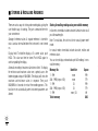
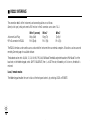
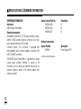
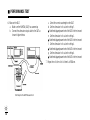
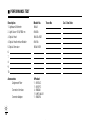
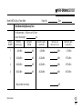
N3970A OPTICAL POWER METER
Operating and
Maintenance Guide
■ N3970A OPTICAL POWER METER SOURCE QUICK REFERENCE GUIDE
■ To remove interchangeable connector, move interface to
mid position, and pull off adaptor.
■ To defeat auto power-off, hold POWER for 3 seconds at
turn on until ON and perm are displayed.
■ To access hidden keypad, pull up display cover.
Select POWER, Source, then:
■ To set reference, push Abs/Rel and hold Set Ref for
3 seconds (3 buzzer sounds).
■ To display reference, hold Abs/Rel, so Ref flashes.
■ To stop / start display update, push Hold.
■ If a test tone is detected, meter will display Hz.
AUTOTEST OPERATION
■ No user action is required for meter to enter Autotest
mode.
■ Autotest: Push Autotest on source and wait a few
seconds.
■ Can also push Autotest on meter for faster lock-on.
■ To display one wavelength only, on the power meter
push the left side of -/+ and again for the other wavelength.
Push right side of -/+ (twice) to exit.
■ Autotest remains for >8 seconds after signal loss, to allow
quick connection change.
■ To exit autotest, remove test lead or turn off source for >8 seconds.
MANUAL OPERATION
■ To turn on and select wavelength, push: POWER, Power
Meter, -/+.
■ To display linear mode, push dBm/W.
■ To display max/min values, push MAX/MIN repeatedly.
Hold MAX/MIN to reset (3 buzzer sounds). .
MEMORY
■ Enter Power Meter or Autotest modes first
■ While in Autotest mode, it is only possible to STORE.
■ To clear all memory, push both RECALL and CANCEL
together for 3 seconds. clr will display.
■ To store in next location, push STORE.
■ To change next store location, push SELECT -/+, SET.
■ To recall, push RECALL -/+ to scroll through data.
■ To exit memory display, push CANCEL.
ADDITIONAL AUTOTEST MEMORY OPERATION
■ To read or cancel memory, first exit Autotest mode, and
enter Power Meter mode.
■ Autotest memory: use -/+ to scroll wavelengths.
■ INTRODUCTION AND APPLICATIONS
N3970A
OPTICAL POWER METER
Congratulations on your purchase of this instrument,
which has been engineered to provide the best possible
reliability, convenience and performance. To get the best
use from your equipment and ensure its safe operation,
please spend a few minutes to read this manual.
1
■ CONTENTS
3
Care of your instrument
19
Introduction & applications
Service and Support
4-5
Accuracy considerations
20-21
Safety Summary
6-7
Calibration, maintenance & instrument returns
22-24
Battery and external power
Optical connector
8
9-10
How to use:
Specifications - Definition of terms
25
Specifications and ordering information
26-28
Performance test
29-38
Getting started and turning on
11-12
Cleaning information
39-40
Autotest operation
13-14
Cleaning procedures
41
Power meter operation
Storing & recalling readings
RS232 interface
15
16-17
Disclaimer & warranty
Notes
42
43-44
18
BEFORE READING FURTHER, OPEN THE CONTROL PANEL PICTURE AT THE BACK OF THE MANUAL
2
■ SERVICE AND SUPPORT
Any adjustment, maintenance, or repair of this product must be
performed by qualified personnel. Contact your customer
engineer through your local Agilent Technologies Service
Center. You can find a list of local service representatives on the
Web at: http://www.agilent.com/find/assist
If you do not have access to the Internet, one of these centers
can direct you to your nearest representative:
United States
Canada
Europe
Japan
Latin America
Australia
New Zealand
Asia-Pacific
1 800 629 485
(613) 9272 0749 (Fax)
0800 738 378
64 4 495 8950 (Fax)
(852) 3197 7777
(852) 2506 9284 (Fax)
1 800 452 4844
1 877 894 4414
(905) 206 4120 (Fax)
(31 20) 547 2323
(31 20) 547 2390 (Fax)
(81) 426 56 7832
(81) 426 56 7840 (Fax)
(305) 269 7500
(305) 269 7599 (Fax)
N3970A UM-1
3
■ INTRODUCTION AND APPLICATIONS
The N3970A Optical Power Meter is used for field or laboratory
testing of fiber optic systems at typically 850, 1300, 1310 and
1550 nm. It features superb measurement confidence, ease of
use and reduced cost of ownership, and is for use by installers,
technicians and engineers.
Superior measurement confidence is achieved with a unique
Total Uncertainty specification over the full temperature,
measurement and connector range, and a NATA traceable
calibration certificate. The display hold and back light facilities
help acquire readings, and the flexible memory helps record
your results
Autotest mode enables automatic λ (wavelength) detection and
attenuation measurement (in combination with an Autotest
source). A single or dual λ source and meter in Autotest mode
automatically measure single or dual λ attenuation in one
direction.
4
High operational reliability & availability is achieved with 250
hour battery life, 3 year recommended re-calibration cycle,
negligible warm up and no range-changing delays. Dark current
offset is not required. An external power input is also provided.
The combination of features enables reduced equipment
inventory, simpler training, shorter procedures, lower skill
levels and direct labour savings in many situations, combining
to give lower cost of ownership.
The innovative optical connector port provides drop protection
during use, and is dust protected by a snap on cover. The
interchangeable optical connector system is very versatile, and
easily disassembled for cleaning.
The simple user interface guides the operator through functional
sequences, and a hidden keypad is used to access advanced
features such as log/linear display, and memory functions.
■ INTRODUCTION AND APPLICATIONS
The tone detector is very sensitive, and is useful for fiber
identification, and calibrating the modulation frequency of test
tone sources.
The instrument has shock absorbent corners, and a tough
polycarbonate housing which has passed extensive drop testing.
Typical applications
■
Singlemode testing, with versatile interchangeable
connectors.
■
Telecom construction, maintenance, CATV, LAN and R&D
applications.
■
Measurements where traceability and documentation are
required.
■
Quality assurance and acceptance tests.
■
Automated testing and reporting using optional Excel software.
■
Test tone measurement & fiber identification.
N3970A UM-1
5
■ SAFETY SUMMARY
The following general safety precautions must be observed
during all phases of operation, service, and repair of this
instrument. Failure to comply with these precautions or with
specific warnings elsewhere in this manual violates safety
standards of design, manufacture, and intended use of the
instrument. Agilent Technologies Inc. assumes no liability for
the customer’s failure to comply with these requirements.
Before operation, review the instrument and manual, for safety
markings and instructions. You must follow these to ensure safe
operation and to maintain the instrument in safe condition.
WARNING
The WARNING sign denotes a hazard. It calls attention to a
procedure, practice or the like, which, if not correctly performed
or adhered to, could result in injury or loss of life. Do not
proceed beyond a WARNING sign until the indicated conditions
are fully understood and met.
6
CAUTION
The CAUTION sign denotes a hazard. It calls attention to an
operating procedure, or the like, which, if not correctly
performed or adhered to, could result in damage to or
destruction of part or all of the product. Do not proceed beyond
a CAUTION sign until the indicated conditions are fully
understood and met.
CAUTION
m
The apparatus will be marked with this symbol when it is
necessary for the user to refer to the instruction manual in order
to protect the apparatus against damage.
■ SAFETY SUMMARY
Initial Inspection
Line Power Requirements
Inspect the shipping container for damage. If there is damage to
the container or Cushioning, keep them until you have checked
the contents of the shipment for completeness and verified the
instrument both mechanically and electrically.
The Performance Tests give procedures for checking the
operation of the instrument. If the contents are incomplete,
mechanical damage or defect is apparent, or if an instrument
does not pass the operator’s checks, notify the nearest Agilent
Technologies Sales/Service Office (see page 3).
The Agilent N3970A Power Meter operates at line power when
applied to the optional external power supply N3979A 9V DC
WARNING
To avoid any hazard, do not perform electrical tests when there
are signs of shipping damage to any portion of the outer
enclosure (covers, panels, and so on).
Operating Environment
The Agilent N3970A Power Meter can be operated at
temperatures between - 10°C and + 55°C and at relative
humidity of <95%.
Storage and Shipment
The Agilent N3970A Power Meter can be stored or shipped at
temperatures between - 25°C and + 70°C and at relative
humidity of less than 95%. Protect the module from
temperature extremes that may cause condensation within it.
REQUIREMENT COMPLIANCE
WARNING
You MUST return instruments with malfunctions to an Agilent
Technologies Service Center for repair and calibration (see page 3).
N 10149
N3970A UM-1
7
■ BATTERY AND EXTERNAL POWER
The instrument is powered by two 1.5V dry batteries (Alkaline C) for
an operating period of typically 250 hours or two 1.2V
rechargeable batteries for an operating period of approximately
125 hours.
Do not use lithium batteries or other batteries with a nominal
voltage greater than 1.8 V. The instrument will be damaged.
When the batteries are low, the low-battery indicator is shown
on the display. At this stage, there is approximately enough
energy for another 30 minutes of use.
For saving of energy the instrument automatically turns off after
10 minutes without operation.
For changing the battery, open the cover of the battery
compartment at the base of the instrument, remove the batteries,
insert new batteries (check polarity) and close the cover again.
Rechargeable batteries must be charged by an external charger.
8
For operation of the instrument by external power use Agilent
AC adaptor N3979A (9V DC, 1.33 A,
).
Use of the external power supply disconnects the batteries.
Ensure that the mains supply has the correct voltage rating and
safety compliance as relevant. Do not use non-compliant or
doubtful mains equipment.
■ OPTICAL CONNECTOR
The optical port is mounted on a swivel, which allows the
connector to be angled outwards for accessibility, and then
pushed back and covered with the snap cover to provide dirt and
drop protection.
The other port can be used to store a spare interchangeable
optical connector.
To install the connector adaptor, align the locating slot on the
side of the adaptor with that on the instrument connector, and
push it on.
To remove the connector adaptor, move the connector port to it’s
mid-way point (see dotted line on diagram at back of manual),
and then pull off the adaptor. It is not possible to remove the
adaptor in the ‘open’ or ‘shut’ positions. With some styles of
connector, it is easier to pull off the adaptor with a test lead in
place, since this gives better grip.
Different styles of connector adaptor ( ST, SC, FC, ) can be
easily fitted by the user.
Optical connectors are precision components, and require care
in use:
■ Always clean the mating connector tip and ferrule before
mating, using approved materials.
■ This instrument can be used with both PC and APC
connector styles (unlike sources, which are factory
configured for PC only ).
■ The soft carry case enables the instrument to be stored
without removing the test leads. This practice saves time,
and is to be recommended.
■ When not in use, keep all test ports and connectors covered
and away from dust.
■ Do not touch connector tips with your fingers,
since body oils and dirt can impair connector performance.
■ Do not use damaged or incompatible connectors.
N3970A UM-1
9
■ OPTICAL CONNECTOR
Cleaning
The glass power meter interface does not make contact with the
inserted connector: there is a slight air gap. Therefore it should
not wear out, and only needs occasional cleaning.
To clean the glass power meter interface: remove the
interchangeable adaptor to access the glass interface, then use
a sticky material such as ‘ Blu tac ‘ to dab the glass and remove
any dirt. A soft brush, alcohol, or air can are also appropriate.
Do not use anything hard that could scratch the glass.
In this manual, refer to the sections on Cleaning Information
and Procedures for further information.
Bare fiber adaptors
Bare fiber adaptors used with this power meter must achieve
fiber eccentricity of +_ 100 microns and end tolerance of
_+ 0.3 mm, relative to the ferrule end. Be careful not to scratch
the detector interface when using adaptors, since permanent
10
meter inaccuracy may result. Preferred bare fiber adaptors
consist of a connector with fiber retention device.
If you work regularly with bare fibers, to avoid potential damage
to the meter, it is generally preferable to use an alternative
arrangement such as a multimode pigtail with a
v-groove or mechanical splice.
■ GETTING STARTED AND TURNING ON
This and following sections show you how to use your
instrument:
This instrument uses a menu driven keypad. The function of
each button is shown on the display.
Check that the correct accessories have been supplied, and an
optical connector adaptor has been fitted. If you have any
queries, call your supplier to resolve the situation.
To access the optical connector, grasp a top corner of the
instrument, and pull off the cover. The connector can be
swivelled to improve access.
Put in the batteries, or plug external power into the socket at the
top of the instrument (see Battery and External Power section).
After instrument turn on, the instrument will perform a selfcalibration sequence, set the dark current adjustment, and then
display absolute power in dBm at the previously set λ. If HI or
LO are displayed, the input is out of range.
The hidden keypad is accessed by pulling up the hinged display
cover. The hidden keypad can operate in two modes. The
second mode is accessed by SHIFT. Access to the second mode
can be denied / permitted by typing the button sequence
: POWER (turn on instrument), SHIFT, CANCEL, SET, SELECT,
RECALL, STORE.
Push the green POWER button. The display will come on.
If the battery is low, this will be indicated on the display.
Pushing POWER again will turn the instrument off.
To stop the instrument turning off 10 minutes after the last key
press, hold POWER down for 3 seconds during turn-on. PERM
on the display indicates that the unit will stay on permanently.
To back light the display temporarily, select LIGHT. To back light
continuously, hold down the button for 3 seconds. Use of the
back light will drain the batteries faster.
N3970A UM-1
11
■ GETTING STARTED AND TURNING ON
To disable or enable the buzzer, hold down SHIFT for 3 seconds.
To add the carry strap: slip the end of the strap through the slit
on the curved section at the back of the instrument, and secure
the buckle.
This instrument requires no warm up, and no user adjustment
of dark current to achieve it’s specified performance.
To learn how to use the instrument features, go to the next
section.
Should the instrument fail to turn on, the microprocessor may
need re-booting. To do this, remove batteries and external
power for at least 40 seconds. This will not lose stored data.
12
■ AUTOTEST OPERATION
General Autotest features
Operation
For Autotest to function, all instruments involved in the test
must be Agilent Handheld instruments with an Autotest
function.
Turn on the source and meter, and connect them with a test lead.
On the light source, push AUTOTEST.
This is all that is required to start Autotest operation on the
power meter.
The meter will automatically set to the correct λ and display
absolute power in dBm. The display will alternate between
wavelengths. To display only one λ at a time, push +/-.
The Autotest feature performs automated measurement (and
automatic λ detection) by data exchange between instruments,
and requires minimal operator knowledge: turn the instrument
on, connect a test lead, and select AUTOTEST on the source.
Subsequent operation is automated, although some choices can
be made for convenience.
Functionality is determined by the options fitted to the
instrument(s) used. Autotest configures itself according to the
options available, and carries out the most comprehensive test
possible.
Autotest remains synchronised for about 8 seconds, which
enables the user to change optical connections without
re-starting Autotest each time.
A light source transmits Autotest signals at one or two
wavelengths to an appropriate power meter.
You may also select AUTOTEST on the meter, which forces the
meter into Autotest mode, with faster synchronisation in this
mode (the source must be in Autotest mode). Push MENU to
exit.
The source power transmitted from the source is displayed on
the left hand side of the display.
Push ABS/REL to make the meter display relative power.
The stored reference value(s) are displayed on the left hand side
of the display.
To take a reference under Autotest, connect the source and
N3970A UM-1
13
■ AUTOTEST OPERATION
meter with a test lead. Set the source to Autotest mode, and then
push SET REF on the meter for 3 seconds. This will store the
reference at all relevant wavelengths.
Either a ‘local’ or ‘remote’ reference can be stored.
To exit Autotest mode, either disconnect the optical test lead, or
exit Autotest mode on the light source for > 8 seconds.
Refer also to manual sections on:
■ Storing and recalling readings.
14
■ POWER METER OPERATION
After instrument turn on, the meter will be calibrated at the last
used λ. To change parameters, push POWER METER, then:
To select a calibrated λ, push +/-. λ is displayed on the top right
side of the display.
To display relative power, push ABS/REL. The display will
show dB R.
To store a new reference, push SET REFfor 3 seconds.
To display the stored reference value, keep ABS/REL depressed.
To change the dBm display between linear and log, access the
hidden keypad and push dBm/W.
If the meter detects a modulated signal, the display will change
to show the actual measured modulation frequency in Hz,
and if a standard tone is detected ( eg 270 Hz, 1 KHz,
2 KHz ), a buzzer will sound. This is useful for fiber
identification and signalling. The meter can also be used to
check the actual modulation frequency of test sources.
N3970A UM-1
15
■ STORING & RECALLING READINGS
There are various ways of storing and recording data, giving the
user flexible ways of working. They are summarised here for
your convenience.
Storage of reference values: A separate reference is stored for
each λ and can be recalled when the instrument is next turned
on.
Display hold: To hold the display at it’s current value, push
HOLD. This value can then be stored. Push HOLD again to
continue updating the display.
Automatic recording of maximum & minimum limits: To display
the minimum and maximum value over a period, access the
hidden keypad and push MAX/MIN. The display will show the
maximum and minimum values in sequence. Then push
MAX/MIN for 3 seconds to re-start the recording process. This
function re-sets automatically when instrument parameters are
altered.
16
Storing & recalling readings using non-volatile memory
In Autotest, stored data includes absolute & relative values at all
possible wavelengths.
Note: To recall data, the unit must be in manual ‘power meter’
mode.
In manual mode, stored data includes absolute, relative and
reference values.
You can store, display or download up to 845 readings in nonvolatile memory.
Memory No
1 - 199
200 - 1990 (steps of 10)
1 - 199
200 - 1990 (steps of 10)
1 - 199
Total memory
Identifier
mem
mem
ID
ID
mem / ID
Space
199
179
199
179
89
845
■ STORING & R ECALLING READINGS
The memory location is shown at the top right of the display.
When storing data, the memory automatically increments to
facilitate the collection of data on a job.
You can also go back and over-write particular records.
After the data has been recorded, the entire memory can be
cleared ready for the next job.
Read from any location: push RECALL, +/-. To display the
relative value, push ABS/REL, and to display the reference, hold
down ABS/REL.
Clear the whole memory: push CANCEL and RECALL together
for 2 seconds. CLR will display.
Memory operating sequence
Store data in next location: push STORE
Store data starting at a particular location: push SELECT, +/-,
SET, STORE
The memory can not be read in Autotest mode. Exit Autotest
before reading the memory.
N3970A UM-1
17
■ RS232 INTERFACE
The connection details of the instrument, and connecting cables are as follows :
Some (out of spec) serial ports need a 10 K resistor in the D connector across wires 1 & 2.
Instrument Jack Plug
9 Pin D connector for RS232
Wire 1 (screen)
Body (Gnd)
Pin 5 (Gnd)
Wire 2
Ring (Tx)
Pin 2 (Rx)
Wire 3
Tip (Rx)
Pin 3 (Tx)
The RS232 interface can be used to access and control the instrument from an external computer. All functions can be accessed
remotely. See next pages for available software.
The baud rate can be set to: 0.3, 0.6, 1.2, 2.4, 4.8, 9.6, 19.2, 38.4, 56 Kbaud. The default and printer baud rate is 9.6 Kbaud. To set the
baud rate, on the hidden keypad, select -SHIFT- BAUD RATE, then -/+ to SET the rate, followed by set. At turn on, the default is
restored.
Local / remote modes
The hidden keypad enables the user to lock out the front panel controls, by selecting LOCAL or REMOTE.
18
■ CARE OF YOUR INSTRUMENT
■ Follow the directions in this manual on cleaning optical
connectors.
■ Limit the input optical power to no more than 5 dB overrange.
■ During storage and transport, keep the instrument in its
carry case to protect against crushing, vibration, dust and
moisture.
■ Clean the instrument using alcohol or other non solvent
cleaning agents. Acetone or other active solvents may
damage the case.
■ The instrument housing is made of tough Polycarbonate
material with impact absorbing rubberised corner features,
and is therefore drop resistant.
■ The instrument is resistant to normal dust and moisture,
however it is not waterproof. If moisture does get into the
instrument, dry it out carefully before using it again.
■ Where possible, keep instrument away from strong sunlight.
■ During prolonged storage, remove batteries to eliminate the
possibility of acid leakage. Use only high quality sealed
alkaline batteries.
N3970A UM-1
19
■ ACCURACY CONSIDERATIONS
All measurements
Optical connectors should be kept clean and in good condition.
Due to emitter center λ uncertainty (eg 1310 +/- 20 nm), fiber
attenuation may vary with different sources.
This λ uncertainty can also affect power meter calibration. This
is significant with InGaAs in the 850 nm band, and absolute
errors in the order of 1 dB are possible. This issue affects
absolute power measurements. It does not significantly affect
attenuation measurements where the meter was referenced to
the same source.
Source power may drift: when you have finished a test, go back
to the start position to check if source power is still within
acceptable limits. It is worth noting that most sources only
quote typical drift after warm up. Actual drift may of course be
significantly worse, and will be very variable between
instruments. The N3974A Dual Laser Source is unusual in
offering maximum drift specifications, without warm up.
20
Most available laser sources ( except the N3974A Dual Laser
Source ) are sensitive to reflections. Varying reflections can
induce source instability of around 0.3 dB. This is very difficult
to verify without a special test system, but can be a source of
errors.
Polarisation changes create disturbances in both the optical
system and measurement equipment. To reduce this, keep your
system physically stable. Keep patch leads neat, coiled and
stable.
The N3970A Optical Power Meter has an InGaAs detector.
■ ACCURACY CONSIDERATIONS
N3970A UM-1
21
■ CALIBRATION & MAINTENANCE
Enabling / disabling ‘shift’ keypad & re-booting the
microprocessor: See section on ‘getting started &
turning on.
Calibration
Calibration can be readily performed without opening the
instrument. Calibration is performed by setting up a singlemode
laser source at a stable but non-critical power level between -10
and -30 dBm, and adjusting the meter reading to the same value
as that shown by a reference meter.
Alternatively, known calibration constants can be
re-entered directly without using other equipment. This is useful
in case old calibration constants are to be put back, or the
instrument memory has been corrupted.
Required are laser light sources with accurate, calibrated
wavelengths and good power stability, a power meter with
appropriate calibrated wavelengths, singlemode test leads, an
anti-tamper label, and a 0.1” programming jumper. Check the
calibration certificates on your reference equipment, to ensure
current validity.
22
To enable calibration mode, open the battery compartment, hold
back the battery spring, remove the anti-tamper label, and insert
a 0.1” pitch programming shunt. Manipulation of the shunt is
easier with needle nose pliers. The meter will display ‘CAL’
Before commencing calibration:
■ Clean all connectors and the meter input ports very carefully
■ Ensure all devices have been at stable room temperature for
over an hour
■ The source is fully warmed up at the λ to be calibrated,
■ The meter battery is good.
On the meter to be calibrated, record the existing calibration
offsets as follows:
■ Select POWER METER, +/- to set the wavelength, and
MAX/MIN twice to display the offsets. Note them down.
(you can also re-enter or adjust known offsets at this point)
■ CALIBRATION & M AINTENANCE
■ Measure and record the source power using the reference
meter
■ Transfer the same power level to the meter to be calibrated,
set MAX/MIN to display power, then +/- to adjust the
reading to match the noted reference reading. Note: The
optical power is measured only when entering this mode. It
is not continuously updated.
Maintenance
CAUTION! Do not open unless the warranty has expired, you are
authorised to do so, and you have a static protected work
station. Opening the unit will invalidate any warranty claim.
There are no internal user adjustable components, fuses, or
calibration features.
The optical sensor / connector assembly is not user serviceable.
Opening the instrument:
■ Set MAX/MIN to read and note the new stored calibration
offsets, and then SET to store and exit, or CANCEL to
abandon and exit
■ Use static protected procedures
■ Go back and check the source power with the reference
meter, to ensure source drift is within limits.
■ Pull open the optical connector covers.
■ When calibration is complete, remove the calibration shunt,
and place an anti-tamper label over the hole in the battery
compartment.
■ Do no forget to update your calibration records, and
schedule the next due date.
■ Remove the batteries, and leave the battery cover open.
■ Place the instrument face down on a soft mat, and undo the
6 screws in the rear housing.
■ The instrument can now be gently pulled apart.
■ The instrument will come into two halves joined by a ribbon
cable. The optical section is located in the bottom half, with
the microprocessor, supply, calibration constants and
controls in the top half.
N3970A UM-1
23
■ CALIBRATION, MAINTENANCE & INSTRUMENT RETURNS
■ Hinged display cover removal can be done at this point.
■ The ribbon connector can be disengaged to completely
separate the instrument halves.
■ Further dis-assembly from this stage should be easily
apparent to a technician.
■ Re-assembly is the reverse of the previous procedure.
Ensure that the ribbon cable connectors are properly
secured so they cannot shake loose. This will be either a
moulded rubber retainer, or adhesive tape.
General electrical parameters are as follows: Vss to GND = 3V3,
-Vss = -3V3, battery power down current about 0.2 mA, active
current about 25 mA.
24
Before returning equipment for repair or calibration, please
check with your local Agilent Technologies Service Center
(see page 3 Service and Support) to obtain a tracking number
and shipping details. If the instrument is being returned for
calibration, please include a purchase order.
Please state clearly the problem requiring attention.
Please include your contact email, phone and fax number, and
return shipping details.
If the goods are under warranty, it would be helpful to include
the original order / contract details.
If the goods are not under warranty, work will only proceed when
a repair order has been issued. Please either include a repair
order with the equipment, or request that a quotation be
provided.
■ SPECIFICATIONS - DEFINITION OF TERMS
Power Range
The range of input powers for which the instrument can be used.
Maximum Input Power
The input power is not to be exceeded to avoid destroying the instrument.
Uncertainty at
reference conditions
The uncertainty for the specified set of reference conditions, including all uncertainties
in the calibration chain from the national laboratory to the test meter (connectors and
patchcords must be absolutely clean and undamaged). Reference conditions are the
conditions during the spectral responsivity calibration.
Total Uncertainty
The uncertainty for a specified set of operating conditions, including noise and drift
(connectors and patchcords must be absolutely clean and undamaged).
Autotest sensitivity
The power level below which the Autotest does not work.
N3970A UM-1
25
■ SPECIFICATIONS & ORDERING INFORMATION
Sensor Element
Wavelength Range
Calibration Wavelengths
Power Range
Maximum Input Power
Uncertainty at reference conditions
Total Uncertainty 3
Autotest sensitivity (typical) 4
Operating Time
Applicable Fiber Type
Optical Input
Display Type
Display Resolution
Display Units
26
2
InGaAs
850-1650 nm
8501, 1300, 1310, 1550 nm
+5 to –60 dBm (850 nm)
+5 to –70 dBm (other wavelengths)
+15 dBm
±0.13 dB (±3%)
±0.3 dB (±7%) ±2pW
-40 dBm (850 nm)
-50 dBm (other wavelengths)
250 hours
9/125 µm to 62.5/125 µm
Non-Contact, Removable Connector Adaptors
LCD, 4 digits
0.01dB, 3 digits in linear mode
dB, dBm, nW, µW, mW
■ SPECIFICATIONS & ORDERING INFORMATION
1: All specifications at 850 nm are typical.
2: 23 ± 3oK, -10 to –30 dBm, calibration wavelengths ± 2nm, fiber type standard SMF, connector type ceramic FC / PC, at day
of calibration.
3: includes uncertainty contributions due to: uncertainty at reference conditions, varying optical connector types, fiber types up
to 62.5 µm core diameter and numerical aperture up to 0.3, operation within power range and within operating temperature range.
4: Tested at room temperature, using an optical attenuator.
Size:
Weight:
Operating / storage:
Power:
Tone detection:
Max / min:
Hidden keypad:
Damage level:
Case:
RS232:
Calibration:
Printing:
190 x 130 x 70 mm, 7.9” x 5.4 x 2.9
500 gm, 1.1 lb. Shipping 2 Kg, 4.4 lb
-10 to 55°C / -25 to 70°C
2 alkaline C cells (7.6 A/hr) or external 9V DC with 2.5mm +ve pin.
Selectable auto-off, low battery indicator, back lit display.
100 - 9999 Hz 1%.
Recording feature for stability testing.
For setting advanced functions.
> 5 dB above max reading.
Polycarbonate, 1 meter drop tested.
3.5 mm jack connector, 0.3 - 56 Kbaud, default 9.6 K.
Performed without opening instrument.
Not supported.
N3970A UM-1
27
■ SPECIFICATIONS & ORDERING INFORMATION
ORDERING INFORMATION
Instrument
N3970A Optical Power Meter
Standard accessories:
Included with instrument: FC, ST, SC optical connector, manual,
batteries, NATA traceable calibration certificate, carry strap,
pouch, protective holster & RS 232 cable.
Connector options: This instrument is equipped with
interchangeable optical connector adaptors, and works with
both PC and APC connectors.
The N3974A Optical Power Meter is supplied with a straight
contact output connector interface. To connect to the
instrument, you must attach your connector interface (see list
connector interfaces below) to the interface adaptor, then
connect your cable.
28
Agilent service Part No.
N3970-63240
N3970-63246
N3970-63251
Description
ST
SC
FC
Optional accessories:
Agilent Part No.
N3979A
Australian and international patents
Description
Power Supply 9V DC
■ PERFORMANCE TEST
The procedures in this section test the performance of the
instrument. The complete specifications to which the Agilent
N3970A Optical Power Meter is tested are given on pages 26-28.
All tests can be performed without access to the interior of the
instrument. The test equipment given corresponds to tests
carried out with Diamond HMS-10 connectors and FC/PC
connectors on the DUT (devise under test).
Equipment Required
Equipment required for the performance test is listed in the table
on page 30. Any equipment that satisfies the critical
specifications of the equipment given in the table may be
substituted for the recommended models.
N3970A UM-1
29
■ PERFORMANCE TEST
Table 1 Required Equipment
Instrument/Accessory
Recommended
Model
Lightwave Multimeter
Interface Module (one
channel)
Optical Head
Laser Souce 1310/1550 nm
8163A
81618A
Optical Attenuator
8156A#101
Connector Interfaces
Connector Adaptors
Singlemode Fiber
81000AI (3ea)
81000FA
81101AC
81101PC
N3970-63251
FC Connector Adaptor for
N3970A
81624A#C01
81654A
Required
Characteristics
Alternative
Models
8164A, 8166A
81619A
1305± 25nm
1550±30nm
Short Term Stability<±0.005 dB
81657A or
81650A & 81651A
or
81655A and 81656A
Attenuation >50 dB
Return Loss >26 dB
Repeatability <±0.01 dB
81101FC
Note: Instead of 8163A, 81618A, 81624A #C01 and 81654A also the older but discontinued equipment 8153A, 81533B, 81524A
#C01 and 81554SM together with 81210LI #011 and 81310LI # 011 can be used.
30
■ PERFORMANCE TEST
Test Record
Instrument Specification
Results of the performance test may be tabulated on the Test
Record provided at the end of the test procedure. It is
recommended that you fill out the Test Record and refer to it
while doing the test. Since the test limits and setup information
are printed on the Test Record for easy reference, the record can
also be used as an abbreviated test procedure (if you are already
familiar with the test procedures). The Test Record can also be
used as a permanent record and may be reproduced without
written permission from Agilent Technologies.
Specifications are the performance characteristics of the
instrument that is certified. These specifications, listed on page
26, are the performance standards or limits against which the
Agilent N3970A can be tested.
Any changes in the specifications due to manufacturing
changes, design, or traceability to the National Institute of
Standards and Technology (NIST), will be covered in a manual
change supplement, or revised manual. Such specifications
supersede any that were previously published.
Test Failure
If the Agilent N3970A fails any performance test, return the
instrument to the nearest Agilent Technologies Sales/Service
Office for repair (see page 3).
N3970A UM-1
31
■ PERFORMANCE TEST
Performance Test
The performance test given in this section includes the
Total Uncertainty/Accuracy Test. Perform each step in the
order given, using the corresponding test equipment.
Total Uncertainty / Accuracy Test
1. Make sure that you satisfy the environmental conditions.
2. Make sure all your connectors are clean.
3. Connect the equipment as shown in figure below.
Note Make sure that all optical connections are dry and
clean. DO NOT USE INDEX MATCHING OIL. For
cleaning, use the cleaning instructions given in "Cleaning
Procedures" on page 41.
Make sure that all patchcords are fixed to the table so that
they won't move during measurements.
Make sure that the ambient conditions are in the
following ranges:
temperature
Relative humidity
23ºC ±3K
45 to 75 %
Test setup for the Uncertainty Test Reference Measurement
Make sure that all Patchcords are fixed to the table and
won't move during measurements.
32
■ PERFORMANCE TEST
4. Switch on the instruments.
a. Switch on the lightwave multimeter.
b. Configure the laser source.
■ Set the laser source attenuation to 0 dB
■ Set the wavelength to 1310 nm
■ Note the actual (displayed) wavelength of the laser source in
the test report
c. Switch on the attenuator.
■ Set the wavelength to the wavelength of the laser source
in the test report
d. Configure the optical head and interface module.
■ Set the unit to dBm
■ Set the averaging time, T, to 100 ms
■ Set AUTO ranging on
■ Set the wavelength to the wavelength of the laser source
■ With the laser source and attenuator disabled, zero
the power meter
e. Switch on the N3970A (DUT) for permanent operation, by
holding the POWER key down for 3 seconds during turn-on
until PERM is shown in the display.
■ Set the DUT to "dBm"
f. Make sure that all the instruments are warmed up.
5. Make the reference measurement.
a. Enable the laser source and the attenuator output.
b. Change the attenuation of the attenuator until the optical
power meter displays -3.00 dBm.
Note In some cases the laser source will not be powerful
enough to give -3.00 dBm. In such case, set the attenuator to
0 dB and correct the appropriate values in the test report.
■ Note the setting of the attenuator for setting 1 in the test report
c. Change the attenuation of the attenuator until the optical
power meter displays -20.00 dBm.
■ Note the setting of the attenuator for setting 2 in the test report
d. Change the attenuation of the attenuator until the optical
power meter displays -30.00 dBm.
■ Note the setting of the attenuator for setting 3 in the test report
e. Change the attenuation of the attenuator until the optical
power meter displays -50.00 dBm.
■ Note the setting of the attenuator for setting 4 in the test report
N3970A UM-1
33
■ PERFORMANCE TEST
6. Measure the DUT.
a. Make sure the N3970A (DUT) has warmed up
b. Connect the attenuator output cable to the DUT as
shown in figure below.
Test Setup for the DUT Measurement
34
c. Select the correct wavelength on the DUT.
d. Set the attenuator to its value for setting 1.
■ Note the displayed power level of the DUT in the test record
e. Set the attenuator to its value for setting 2.
■ Note the displayed power level of the DUT in the test record
f. Set the attenuator to its value for setting 3.
■ Note the displayed power level of the DUT in the test record
g. Set the attenuator to its value for setting 4.
■ Note the displayed power level of the DUT in the test record
7. Repeat from list item 4 to list item 6 at 1550 nm.
■ PERFORMANCE TEST
Model N3970A Optical Power Meter
Date
Serial No.
Ambient Temperature
oC
Options
Relative Humidity
%
Firmware Rev.
Line Frequency
Hz
Test Facility
Customer
Performed by
Report No
Special Notes
N3970A UM-1
35
■ PERFORMANCE TEST
Description
1. Lightwave Multimeter
Model No.
8163A
2. Light Source 1310/1550 nm
81654A
3. Optical Head
4. Optical Head Interface Module
81624A #C01
81618A
5. Optical Attenuator
8156A #101
6.
7.
8.
9.
10.
Accessories
Singlemode Fiber
Connector Interfaces
Connector Adaptors
36
#Product
1 81101AC
1 81101PC
3 81000AI
1 N3970-63251
1 81000FA
Trace No
Cal. Due Date
■ PERFORMANCE TEST
Model N3970A Optical Power Meter
Report No.
Date
Total Uncertainty/Accuracy Test
Test Wavelengths = 1300 nm and 1310 nm
Source Wavelength =
Setting
Number
Reference
(8163A Display)
nm
Attenuator
Setting
Minimum Spec.
N3970A, DUT
Maximum Spec.
(-0.3 dB of Ref.)
Measurement results
(+0.3 dB of Ref.)
1
-3.00 dBm
dB
-3.30 dBm
dBm
-2.70 dBm
2
-20.00 dBm
dB
-20.30 dBm
dBm
-19.70 dBm
3
-30.00 dBm
dB
-30.30 dBm
dBm
-29.70 dBm
4
-50.00 dBm
dB
-50.30 dBm
dBm
-49.70 dBm
Measurement Uncertainty
dB
N3970A UM-1
37
■ PERFORMANCE TEST
Model N3970A Optical Power Meter
Report No.
Date
Total Uncertainty/Accuracy Test
Test Wavelengths = 1550 nm
Source Wavelength =
Setting
Number
Reference
(8163A Display)
nm
Attenuator
Setting
N3970A, DUT
Maximum Spec.
(-0.3 dB of Ref.)
Measurement results
(+0.3 dB of Ref.)
1
-3.00 dBm
dB
-3.30 dBm
dBm
-2.70 dBm
2
-20.00 dBm
dB
-20.30 dBm
dBm
-19.70 dBm
3
-30.00 dBm
dB
-30.30 dBm
dBm
-29.70 dBm
4
-50.00 dBm
dB
-50.30 dBm
dBm
-49.70 dBm
Measurement Uncertainty
38
Minimum Spec.
dB
■ CLEANING INFORMATION
The following Cleaning Instructions contain some general
safety precautions, which must be observed during all phases of
cleaning. Consult your specific optical device manuals or
guides for full information on safety matters.
Please try, whenever possible, to use physically contacting
connectors, and dry connections.
Clean the connectors, interfaces, and bushings carefully after use.
If you are unsure of the correct cleaning procedure for your
optical device, we recommend that you first try cleaning a
dummy or test device.
Agilent Technologies assume no liability for the customer's
failure to comply with these requirements.
For more information about Cleaning Instruments, please
consult the Pocket Guide "Cleaning Procedures for Lightwave
Test and Measurement Equipment" (Agilent P/N 5963-3538F).
If you do not have a copy of this pocket guide, Agilent will
provide you with one free of charge.
Safety Precautions
Please follow the following safety rules.
■ Do not remove instrument covers when operating.
■ Ensure that the instrument is switched off throughout the
cleaning procedures.
■ Use of controls or adjustments or performance of procedures
other than those specified may result in hazardous radiation
exposure.
■ Make sure that you disable all sources when you are cleaning
any optical interfaces.
■ Under no circumstances look into the end of an optical
device attached to optical outputs when the device is
operational. The laser radiation is not visible to the human
eye, but it can seriously damage your eyesight.
■ To prevent electrical shock, disconnect the instrument from
the mains before cleaning. Use a dry cloth, or one slightly
N3970A UM-1
39
■ CLEANING INFORMATION
dampened with water, to clean the external case parts. Do not
attempt to clean internally.
Do not install parts or perform any unauthorised modification to
optical devices.
* Refer servicing only to qualified and authorised personnel.
Why is it important to clean optical devices ?
In transmission links optical fiber cores are about 9 µm
(0.00035") in diameter. Dust and other particles, however, can
range from tenths to hundredths of microns in diameter. Their
comparative size means that they can cover a part of the end of
a fiber core, and as a result will reduce the performance of your
system.
Furthermore, the power density may burn dust into the fiber and
cause additional damage (for example, 0 dBm optical power in
a single mode fiber causes a power density of approximately 16
million W/m2). If this happens, measurements become
40
inaccurate and non-repeatable. Cleaning is, therefore, an
essential yet difficult task. Unfortunately, when comparing most
published cleaning recommendations, you will discover that
they contain several inconsistencies. In this section, we want to
suggest ways to help you clean your various optical devices,
and thus significantly improve the accuracy and repeatability of
your lightwave measurements.
■ CLEANING PROCEDURES
Keep your dust and shutter caps on when your instrument is not
in use. This should prevent it from getting too dirty. If you must
clean such instruments, please refer the instrument to the
skilled personnel of Agilent's service team.
Preferred Procedure
Use the following procedure on most occasions.
1. Blow away any dust or dirt with compressed air.
If this is not sufficient, then
a. Clean the interface by rubbing a new, dry cotton swab
o v e r the surface using a small circular movement.
b. Blow away any remaining lint with compressed air.
Procedure for Stubborn Dirt
Use this procedure when there is greasy dirt on the interface,
and using the procedure for light dirt is not sufficient. Using
isopropyl alcohol should be your last choice for recessed lens
interfaces because of the difficulty of cleaning out any dirt that
is washed to the edge of the interface.
1. Moisten a new cotton swab with isopropyl alcohol.
2. Clean the interface by rubbing the cotton swab over the
surface using a small circular movement.
3. Take a new, dry soft tissue and remove the alcohol, dissolved
sediment and dust, by rubbing gently over the surface using
a small circular movement.
4. Blow away any remaining lint with compressed air.
N3970A UM-1
41
■ DISCLAIMER & WARRANTY
Information in this manual is given in good faith for the benefit
of the user. It cannot be used as the basis for claims against
Agilent Technologies or its representatives, if accidental
damage or inconvenience results from use or attempted repair
of the equipment.
Agilent Technologies products are guaranteed against defective
components and workmanship for a period of 3 years from the
date of delivery, unless specifically stated in the original
purchase contract or agreement. This warranty excludes optical
connectors or incorrect use. Opening the instrument will
invalidate the warranty. Liability is limited solely to repair of the
equipment.
42
■ NOTES
N3970A UM-1
43
■ NOTES
44