1
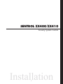
SENTROL ZX400/ZX410
Security System Control
Installation
1
2
TABLE OF CONTENTS
Table of Contents
New Features ............................................................................................................. 5
ZX400/ZX410 Wiring Diagrams................................................................................ 6
ZX400/ZX410 Terminal Descriptions ........................................................................ 8
“2 in 1” Zoning™ ...................................................................................................... 9
Conventional Methods of Wiring ........................................................................... 11
Class ‘B’ End-Of-Line Resistor Supervised Zones ..................................................... 11
Non-Supervised Closed Circuit Loop (No EOL Resistor Supervision) ...................... 11
Control Station Addressing and Supervision ......................................................... 12
SSD, LCD, and VFD Control Stations ...................................................................... 12
LED Control Stations .............................................................................................. 12
Control Station Troubleshooting ............................................................................ 13
Clearing Trouble Messages ..................................................................................... 13
12 VDC Outputs ...................................................................................................... 14
Additional Outputs .................................................................................................. 14
Expansion Zones ..................................................................................................... 16
ZXEXP Zone Expander Module ............................................................................... 17
Installation ............................................................................................................. 17
Wireless Devices ...................................................................................................... 18
Fire Zone Modules .................................................................................................. 19
ZEM Zone Expansion Module ................................................................................ 19
ZRM Zone Relay Module ........................................................................................ 21
ZXCFK Fire Module Kit ........................................................................................... 21
Power Issues ............................................................................................................ 22
Optional Battery Configurations ............................................................................. 22
ZX400/ZX410 Power Worksheet ............................................................................ 22
Auxiliary Power Supply Installation ......................................................................... 23
ZXPTR Printer Interface Module ............................................................................. 24
3
TABLE OF CONTENTS
Specifications And Features .................................................................................... 25
Control Board ........................................................................................................ 25
Power Supply ......................................................................................................... 25
Recommended Battery ........................................................................................... 25
Recommended Transformer ................................................................................... 25
Enclosure ................................................................................................................ 25
Digital Communicator ............................................................................................ 25
Control Stations ..................................................................................................... 26
ZXLCD Control Station ........................................................................................... 26
ZXVFD Control Station ........................................................................................... 26
ZXLED12 Control Station ....................................................................................... 26
ZXSSD Control Station ........................................................................................... 26
Optional Accessories .............................................................................................. 26
Output Provisions ................................................................................................... 27
List Of Compatible Accessories ............................................................................... 28
ESL Two-Wire Smoke Detectors .............................................................................. 28
ESL Four-Wire Smoke Detectors .............................................................................. 28
System Sensors Two-Wire Smoke Detectors ............................................................ 28
System Sensors Four-Wire Smoke Detectors ........................................................... 28
Wheelock ............................................................................................................... 28
Compatible Central Station Receivers ..................................................................... 28
Agency Requirements ............................................................................................. 29
UL and ULC Listings ............................................................................................... 30
National Fire Protection Association (NFPA) Rules ................................................ 31
Smoke Detector Locations ...................................................................................... 31
Testing ................................................................................................................... 31
System Troubleshooting ......................................................................................... 32
FCC Compliance ...................................................................................................... 34
4
NEW FEATURES
New Features
• 12 Zones with Sentrol’s unique “2 in 1” Zoning™
• Plus one 2-wire fire zone
• Expandable to 28 zones, plus two 2-wire fire zones
• Integrated Sentrol Series 4000 Wireless
• Two truly independent partitions
• Up to 50 user codes with 15 levels of authority
• 75 event log
• Four interchangeable Control Stations to choose from
• Customized scheduling with special supervisory report
• Ideal for residential, commercial, and industrial applications
• Control Station programming in less than 2 minutes with factory defaults
The Sentrol ZX400/ZX410 Security Control features
ease of installation and programming. The ZX400/
ZX410 is easily programmed with any one of four
Control Stations (LCD, LED, SSD, or VFD). The control may also be programmed remotely with the aid
of a personal computer (PC) and a modem using
Sentrol’s remote programming software (RPM2PRO)
and a panel support module (PRO400). The Control
Stations are easy-to-operate and contain features
such as cross-zoning, delay-before-dialing and an
audibles “mute” function to help reduce false alarms.
ity. Using the Series 4000 Wireless System, you can
expand the ZX400/ZX410 to include up to 16 wireless zones.
The Control’s on-board RAM maintains its data even
with the power disconnected. A “Watchdog” timer
monitors the microprocessor to ensure the operational integrity of the system. The ZX400/ZX410
Control Board is equipped with one low current programmable output (PGO1) and one high current bell
output (BELL) which may be used for Fire, Burglar,
Auxiliary and/or Holdup alarms. In addition, two
ZXODMs (Output Driver Modules) can be added to
provide 20 more programmable low current outputs which may be used to trigger other devices.
The ZX400/ZX410 Security Control is pre-programmed from the factory with twelve burglar zones
(one delay, two interior, and nine instant) and one
2-wire smoke detector zone to allow for out-of-box
power-up and operation. The twelve burglar zones
have been configured in a ‘paralleled’ condition using Sentrol’s unique “2 in 1” Zoning™. A zone expander may be added to provide an additional 2wire smoke detector zone and, with the use of “2 in
1” Zoning™, up to 16 additional zones.
The ZX400 Security Control may be purchased in
the ZX410 pre-configured package assembly. This
assembly incorporates the ZX400 Control Board
mounted inside a larger 14" x 14" x 3.5" enclosure,
EX1414. The ZX410 must be purchased for Commercial and Industrial UL Listed applications. For UL
Listed Commercial Fire applications, the ZX440F is
available. It consists of the ZX400 Control Board in
a red EX1414 enclosure, with a ZXCFM (Commercial Fire Module), a CR860 dual battery harness and
other cabling.
Sentrol Series 4000 RF Gateway receivers and sensors allow you to overcome installation obstacles and
increase profit potential. The wireless sensors have
been engineered for long term stability and reliabil-
5
ZX400/ZX410 WIRING DIAGRAMS
ZX400/ZX410 Wiring Diagrams
TEL
SUPV
J-3
Class II
PowerLimited
ON
I.C. Load Number 1
Class II
PowerLimited
PG01
OFF
J-10
J-4
11
NEG
1500Ω EOL
SUPERVISION
13
Z2/8
15
Z3/9
14
NEG
Basler BE 116235
16.5VAC/35VA
U.L. Class II 50/60Hz
16
Z4/10
17
NEG
N.C.
N.C.
N.C. ZONE 1
ZONE 9
825Ω
1/4 WATT
825Ω
1/4 WATT
N.C.
Ademco AB12M
-
-
+
TO ANY ZONE DEFINED
AS 24-HOUR FIRE
7
5
NEG BELL
+
POLARIZATION AND
NOISE SUPPRESSION
DIODE
MOTION
DETECTOR
RED
BROWN
QUIESCENT CHARGE
CURRENT: 20mA.
Replacement: Every 3 - 5 years.
BROWN
POWER SUPERVISION UNIT
ESL MODEL 204-12/24V OR EQUIV.
+
+
-
POWER
+
1500Ω (CR854)
(EOL DEVICE)
1500Ω (CR854)
(EOL DEVICE)
BLACK
FLOAT BATTERY VOLTAGE:
13.6 - 13.8V
Max. current: 500mA.
CONNECTION OF UL COMMERCIAL
BURGLAR AUDIBLE
POWER
LISTED RATE OF RISE OR
FIXED TEMPERATURE THERMOSTAT
12V SEALED
LEAD ACID BATTERY
Yuasa B-1270
CONNECT
RJ31/33/45
CORD
ZONE 5
1500Ω
1/2 WATT
N.C. ZONE 11
1500Ω
1/2 WATT
1500Ω
1/2 WATT
20
NEG
METHOD 2
ZONE 3
UL LISTED
SIGNALING DEVICE
Internally Fused.
Do Not Short.
Do Not Connect
To A Switched
Receptacle.
18
19
Z5/11 Z6/12
METHOD 1
N.O.
CONTROL STATIONS
ZONE EXPANDER
PRINTER INTERFACE
ODMs
TRANSFORMER
WARNING
12
Z1/7
BLACK
GREEN
8
9
10
DAT A DAT B KP+12
RED
7
NEG
6
2WS
JUMPER
UNIFIED
EARTH
GROUND
Red and Black Leads RED = POS. (+) BLACK = NEG. (-)
Enclosure
Door
Ground
Wire
4
5
3
SW NEG AUX12 BELL
1
2
AC XFMR
WHITE
~
GROUND
SCREW
-
SMOKE DETECTOR
SENTROL 2-WIRE MODELS
(See ZX400/ZX410 Interconnect Label
P/N 64600310-NOTE 2)
1500Ω (CR854)
(CONV ZONING)
ALARM
CONTACTS
UL LISTED RESISTORS
MODEL CR853 - 825Ω E.O.L.
MODEL CR854 - 1500Ω E.O.L.
SMOKE DETECTOR
SENTROL 4-WIRE MODELS
(See ZX400/ZX410 Interconnect Label
P/N 64600310-NOTE 2)
See Specification and Features section for a complete list of compatible accessories.
FIGURE 1
Suggested UL Household Burglar Alarm and/or Fire (ƒƒ) Alarm Hookup
6
13
Z2/8
ALL WIRING
BETWEEN CONTROL
& BELL MUST BE IN
CONDUIT.
ADEMCO AB12M
GRADE A BELL
COMMERCIAL
ZX400/ZX410 WIRING DIAGRAMS
TG - COM
NC
NO
MPI-206
TELEPHONE
SUPERVISION
CONNECTION
TO TERMINAL 7
+12V
NEG
TG+
INSTALL
JUMPER
TEL
SUPV
CUT
JUMPER
SENTROL RJ38 CORD
(shown)
+12V
TO TERMINAL 10
TO TERMINAL 20
OPTIONAL - When Telco Supervision is required
OPTIONAL - When relay is required
FIGURE 2
Programmable Output And Telco Supervision Wiring Diagram
7
BLUE
TG - COM
TG+
PG01
NEG
PROGRAMMABLE
OUTPUT 1
CONNECTION
ORANGE
J4
NC
MPI-206
NO
TO TERMINAL 4
ZX400/ZX410 TERMINAL DESCRIPTIONS
ZX400/ZX410 Terminal Descriptions
TERMINAL
FUNCTION
1, 2
AC Input
3
Switched Negative
(-) Current limited 100 mA terminal. Negative connection for 4-wire smoke
detectors, glass break detectors, and devices requiring resettable power.
4
Auxiliary Power
(+)12 VDC 500 mA continuous power. Overcurrent protected at 1.35 amps
(PTC4). Used for powering motion detectors, 4-wire smoke detectors, glass
break detectors, and other accessories.
CAUTION: Use terminals 4 and 10 when calculating total current drain.
5
Supervised Bell Output
(power-limited)
(+)12 VDC. Combined alarm current should not exceed 1.5 amps. Overcurrent
protected at 1.85 amps (PTC2). A 1500 Ohm EOL resistor (CR854) must be connected between terminals 5 and 7; otherwise a bell output fault will occur.
6
Two Wire Smoke (Zone 30)
(power-limited)
7, 11
Common Negative
(power-limited)
(+)12VDC of two-wire smoke detectors connected to this terminal. A 1500
Ohm EOL resistor (CR854) must be connected between terminals 6 and 7
regardless of whether a two-wire smoke detector is used or not. The maximum
series resistance is 60 Ohms.
BLACK WIRE - (-)12 VDC. Negative connection for Control Stations, zone
expander, printer interface, RF Gateway, ODMs, 2-wire smoke detectors,
motion detectors, and other devices.
8
Local Data Bus In (A)
GREEN WIRE - Connection for Control Stations, zone expander, printer
interface, RF Gateway and ODMs. Use 22 guage wire up to 1000 ft. Use 18
guage wire up to 2000 ft.
9
Local Data Bus Out (B)
WHITE WIRE - Connection for Control Stations, zone expander, printer
interface, RF Gateway and ODMs. Use 22 guage wire up to 1000 ft. Use 18
guage wire up to 2000 ft.
10
Control Station Power
(power-limited)
RED WIRE - (+)12 VDC 500 mA continuous power connection for control
stations, zone expander, printer interface, RF Gateway and ODMs. Overcurrent
protected at 1.35 amps (PTC4).
CAUTION: Use terminals 4 and 10 when calculating total current drain.
12
13
14
15
16
17
18
19
20
Zone 1/7 Loop (+)
Zone 2/8 Loop (+)
Common Negative
Zone 3/9 Loop (+)
Zone 4/10 Loop (+)
Common Negative
Zone 5/11 Loop (+)
Zone 6/12 Loop (+)
Common Negative
PGO1
Programmable Output 1
TEL SUPV
Telephone Supervision
J4
Telco Jack
DESCRIPTION
Connect the appropriate UL Class II transformer using 18 gauge minimum 2
conductor wire. Do not exceed 50 feet. Use a 16.5 VAC 35 VA transformer or an
optional 16.5 VAC 20 VA transformer.
CAUTION: Do not short the terminals of the transformer together. This
causes the internal fuse to blow. The transformer must be connected to a
120 VAC, 24-hour outlet not controlled by a switch other than an approved
over-current protection device.
Each loop requires a 1500 Ohm end-of-line resistor (P/N CR854) for the primary
zone, and an 825 Ohm end-of-line resistor (P/N CR853) for the secondary zone.
A common negative is shared among all zones. The need for end-of-line resistors
may be eliminated on all Burglar defined zones through programming. See
Figure 1 for “2 in 1” Zoning™ wiring examples.
Use PGO1 as a +12V, 40 mA programmable output (see Figure 2).
Use TEL SUPV as a telephone line trouble input (see Figure 2).
RJ-31X connection.
8
“2 in 1” Zoning™
“2 in 1” Zoning™
NOTE
If a Normally Open Device (i.e., 4-wire
smoke detector) is used with “2 in 1”
Zoning™, a short will occur across
both zone loops when that device
goes into alarm. It is recommended
that these types of devices be used
with Conventional Zone wiring only.
Method 2 wires two separate zone loops back into
one set of terminals. The panel recognizes each
loop independently because two different EOL resistor values are used to differentiate between the
Primary Zone (1500 Ohm 1/2 Watt) and the Secondary Zone (825 Ohm 1/4 Watt). This method
provides two zones with one set of terminals and is
ideal for pre-wire or already installed wiring.
The Sentrol ZX400/ZX410 Security Control introduces an all new method of wiring zones that saves
both time and wire costs. “2 in 1” Zoning™ allows
the installer to wire two separate zones in parallel
into one set of terminals.
1500Ω 1/2W
Primary Zone
Each zone is uniquely identified by its end-of-line resistor. The Primary Zone (zones 1-6) in each terminal is identified by a 1500 Ohm EOL resistor. The
Secondary Zone (zones 7 - 12) is identified by an
825 Ohm EOL resistor. The Primary and Secondary
zones operate as two independent zones to provide
separate reporting, programming, and displays. Each
zone is fully programmable as described in the
ZX400/ZX410 Programming Manual. The zones are
for Form A, Form B, or Form C sensors. Maximum
total loop wire and contact resistance (not including EOL) must not exceed 100 Ohms for the loop
to function properly.
Secondary Zone
825Ω 1/4W
Figure 4
NOTE
The resistors in Figure 3 & 4 are 1%
values to maintain proper loop resistance values. If replacements are required, please refer to the manufacturer for correct replacements. The
1500 ohm resistor is color coded
Brown•Green•Black•Brown•Brown.
The 825 ohm resistor is color coded
Gray•Red•Green•Black•Brown.
There are two methods of wiring for “2 in 1” Zoning™. Method 1 wires one zone loop back to the
control while a second zone loop is added in parallel
off the first. This method may be employed in system retrofits, system expansions, or just simply to
save wire cost and labor.
All zones sense five different voltage levels enabling
one zone to act as two. Troubleshooting is simple
using just a voltmeter at the control. The control
monitors the voltage level across the zone and uses
the voltage levels in Table 1 to determine whether
the zone is normal, open, or shorted.
1500Ω 1/2W
Primary Zone
Secondary Zone
825Ω 1/4W
Figure 3
“2 in 1” Zoning™ Wiring - Method 2
“2 in 1” Zoning™ Wiring - Method 1
9
“2 in 1” Zoning™
CONDITION
NOMINAL LOOP RESISTANCE
VOLTAGE READING
Primary Zone and Secondary Zone
Open Contacts; Loop Cut or Open
Infinite Ohms
5.24 - 8.25 V
Secondary Zone Open Contact,
Primary Zone Normal
1500 Ohms
4.24 - 5.23 V
Primary Zone Open Contact,
Secondary Zone Normal
825 Ohms
3.24 - 4.23 V
Primary Zone and Secondary Zone
Normal
825 Ohms in parallel with
1500 Ohms = 532 Ohms
2.00 - 3.23 V
Primary Zone and Secondary Zone
Shorted
0 Ohms
TABLE 1
“2 in 1” Zoning™ Troubleshooting Chart
10
0 - 1.99 V
CONVENTIONAL WIRING
Conventional Methods of Wiring
Class ‘B’ End-Of-Line Resistor
Supervised Zones
Non-Supervised Closed Circuit
Loop (No EOL Resistor
Supervision)
A Class ‘B’ zone must be supervised with a 1500
Ohm 1/2 Watt end-of-line resistor (P/N CR854). This
resistor should be installed in series at the furthest
point from the control. This configuration must be
used whenever both Form A and Form B devices are
connected and provides a high degree of protection against compromise or tampering. The control
monitors the voltage level across the Primary zone
and uses the Primary zone voltage levels in Table 1
to determine whether the zone is normal, open, or
shorted. The operation of a zone is programmable
as described in the ZX400/ZX410 Programming
Manual. Maximum total loop wire and contact
resistance (not including EOLs) must not exceed
100 Ohms for the loop to function properly. The
1500 Ohm EOL resistor is optional for Form A connections but is required for Form B.
The EOL resistor is not required on Burglar zones. A
conventional closed circuit loop may be connected
directly to a primary zone and the zone will have
either a short or an open condition. See the ZX400/
ZX410 Programming Manual for programming an unsupervised zone. Fire zones may not be installed as
unsupervised. Only Burglar defined zones may be
wired non-supervised. “2 in 1” Zoning™ is not
allowed.
Normally
Open
1500Ω 1/2W
Primary Zone
Normally
Closed
Figure 5
Conventional Zone Wiring Method
NOTE
For UL Listed systems, EOL Supervision is required.
11
CONTROL STATION ADDRESSING AND SUPERVISION
Control Station Addressing and Supervision
All Control Stations are shipped from the factory as
Control Station #1 and supervised. They may be set
to other addresses and to unsupervised as described
below.
NOTE
When unsupervised Control Stations
are used, ALL unsupervised LED Control Stations must be addressed as 1
or 2, ALL unsupervised SSD Control
Stations must be addressed as 3 or 4,
and ALL unsupervised LCD/VFD Control Stations must be addressed as 5
or 6. You cannot mix a supervised
Control Station and unsupervised
Control Station with the same address
setting.
A supervised Control Station is reported as missing
when the system fails to get any response from it.
In order to maintain supervision, each supervised
Control Station must have its own unique address.
An unsupervised Control Station can be removed
from the system without the system detecting that
it is missing. The advantage of an unsupervised Control Station is that a system can have as many Control Stations as the power supply can support. By
adding additional power supplies, like the HCP12SULC, Control Stations may be added up to a total of 13 bus devices on the system. For UL listed
systems, unsupervised Control Stations are not allowed.
LED Control Stations
These Control Stations have two jumpers on the circuit board to set the address and supervision. To
change the address of the Control Station #1 to
Control Station #2, remove JP2 (see Figure 7). To
change a Control Station to unsupervised, remove
JP1 (see Figure 7).
SSD, LCD, and VFD Control
Stations
Remove JP1 to unsupervise
These Control Stations have a four position DIP
switch on the circuit board to set the address and
supervision. To change the Control Station to unsupervised, move DIP switch 4 to the ON position. To
change the address, the DIP switch setting must be
positioned according to Figure 6.
2
1
ON
Figure 7
1234
5
6
ON
OFF
1234
JP2
OFF
ON
Figure 6
3
1234
4
Remove JP2 for keypad 2
ON
OFF
1234
JP1
OFF
1234
1234
Control Station DIP Switch Settings
12
LED Control Station Jumpers
CONTROL STATION TROUBLESHOOTING
Control Station Troubleshooting
If a Control Station is incorrectly wired, it will not
accept keystroke entries. The following symptoms
may appear:
SYMPTOM
CONDITION
No Control Station LED’s or display
Black or Red Wire removed or cut
No response from key presses
Green Wire removed or cut or two supervised
Control Stations at the same address
LED’s flash and may display “No Communication
From Control” code
White Wire removed or cut
Green/White Wires reversed
Green & White Wires shorted together
The nominal voltage at the control with a single Control Station connected should measure as follows:
TERMINAL
VOLTAGE
from Common Negative (Terminal 7 or 11) to Data A (Terminal 8)
~ 11.5 VDC
from Common Negative (Terminal 7 or 11) to Data B (Terminal 9)
~ 7.7 VDC
from Common Negative (Terminal 7 or 11) to Control Station Power (Terminal 10)
~13.8 VDC
Clearing Trouble Messages
Once the system is up and running, trouble conditions may occur. Most trouble conditions are cleared
automatically when the condition that initiated the
trouble is restored or is eliminated. Three trouble
conditions (Memory Error, Smoke Trouble and Missing Keypad) may be cleared manually by pressing
and holding the Clear key for three seconds (until
two beeps are heard). This action is also required to
turn off the Duress output after it has been activated
and to cause an “Installer Off Premises” event (see
Operating the System - Installer On Premises).
A Bell Silenced trouble condition may only be cleared
by performing a smoke reset operation.
13
12 VDC AND ADDITIONAL OUTPUTS
12 VDC Outputs
ZXODM
The ZX400/ZX410 control provides one switched
negative output, one Control Station power output,
one auxiliary power output, one 2-wire smoke power
terminal, one bell output, and one programmable
low current output (PGO1). (See Figure 1).
OUTPUTS
J1
J3
1 2 3 4 5 6 7 8 9 10 NEG 12V
ZX400/ZX410
D2
D1
Additional Outputs
1
2
AC XFMR
4
5
3
SW NEG AUX12 BELL
Additional outputs can be added with the ZXODM
Output Driver Modules. Each module receives its
data from the local data bus and provides ten additional programmable outputs. The outputs provide
+12 VDC on activation and must be limited to 40
mA of current draw. ODM1 has 10 unique outputs.
ODM2 also has 10 unique outputs.
6
2WS
7
NEG
8
9
10
DAT A DAT B KP+12
11
NEG
12
Z1/7
13
Z2/8
14
NEG
15
Z3/9
Figure 8
The ODMs may be addressed as ODM1 or ODM2.
You may use multiple ODMs at a given address provided that power restrictions are followed. The
ODMs come defaulted from the factory as ODM1.
To change from ODM1 to ODM2, remove power,
cut resistor R29, and re-apply power. Connect the
ODMs to the control as shown in Figure 9. Use the
twelve (12) wire cable provided with the ODMs for
the outputs as shown.
16
Z4/10
17
NEG
18
19
Z5/11 Z6/12
20
NEG
ZXODM Mounting
DATA BUS CONNECTION
Connect to Control terminal 10
Connect to Control terminal 8
Connect to Control terminal 9
Connect to Control terminal 7
CONTROLS GROUP
D8
C1
C8
C9
C2
R18
R19
Y1
C10
D4
C11
D5
D10
SENTROL
U1
R1
HICKORY, NC
60821484 REV A
COPYRIGHT 1996
Q2
ACTIVE
R17
RED
GREEN
WHITE
BLACK
+
D3
C7
R11
R9
R8
R7
R6
R10
J3
R28
D7
OUTPUTS
1 2 3 4 5 6 7 8 9 10 NEG 12V
12V A B NEG
A ZXODM may be mounted in the control enclosure using the double-sided tape provided on the
back of the module. For UL Certificated installations requiring rigid mounting, a ZXODM may be
mounted in a ZX410 control enclosure as shown
in Figure 8 using the stand-offs provided in the
ZEM/ODM Mounting Hardware Pack (P/N
13000515).
R4
J1
R5
R26
+
V1
J2
R2
R3
R24
R22
R23
R25
C5
+
D9
V2
D6
R29
C6
D1
D2
V3
U4
ASSEMBLED
IN USA
U2 C3
C4
R16
PC BOARD
MADE IN (USA)
R21
R14
R13
R27
R12
Output conditions can be programmed as one of
many conditions. Refer to the ZX400/ZX410 Programming Manual for programming information and
restrictions.
R15
R20
Q1
Data bus connection
Remove for ODM #2
J3 Connector
J3 CONNECTIONS
NOTE
The outputs on this module have limited transient immunity and should
not leave the enclosure.
OUTPUT
WIRE COLOR
DEFAULT
DESCRIPTION
1
Tan
13
Burglar
2
Pink
3
Fire
3
Gray
14
Holdup
4
Violet
15
Auxiliary/Medical
5
Yellow
19
Arm AWAY
6
Orange
31
Chime
7
Blue
18
Ready
8
Dk Brown
25
Pre-Alarm
9
Green
34
Lamp
10
White
39
Access
NEG
Black
12V
Red
Figure 9
14
ZXODM Wiring Diagram
12 VDC AND ADDITIONAL OUTPUTS
Outputs may be wired to indicator devices or relay module triggers (like the MPI-206) provided
the 40 mA current draw condition is not exceeded.
Figure 10 shows a wiring example for a relay to
ODM 1 Output 2. Figure 11 shows a wiring example of ODM 1 Output 1 to trigger an LED.
Output 1
Neg
TAN WIRE
Connects to J3 (part of 12-wire cable)
FIGURE 11
Output 2
Neg
PINK WIRE
TRIG +
NEG
NOTE
N.O.
The LED & 470 Ohm current limiting
resistor shown in Figure 11 are not
supplied.
Connects to J3 (part of 12-wire cable)
+12V on Trig. Input
connects common to
N.O. terminals
FIGURE 10
Output Connected to an LED
N.C.
COM
BLACK WIRE
470Ω
BLACK WIRE
Output Connected to a Relay
NOTE
Do not exceed 250 mA of total current through the Red (+12V) and
Black wires (Negative) of the twelve
wire cable. Add 18 gauge wire from
the appropriate control panel terminals for total current drains in excess
of 250 mA.
15
EXPANSION ZONES
Expansion Zones
Zones 13-28 are expansion zones. They may reside
on any zone expansion device (ZXEXP, ZEM, RF Gateway 1 or RF Gateway 2). Assignment of these zones
to expansion devices is done through programming
(see ZX400/ZX410 Programming Manual).
The options available for all zones are described in
the table below.
ZONE
ON-BOARD
ZXEXP ZONE
1
On-Board Zone 1 Primary
2
On-Board Zone 2 Primary
3
On-Board Zone 3 Primary
4
On-Board Zone 4 Primary
5
On-Board Zone 5 Primary
6
On-Board Zone 6 Primary
7
On-board Zone 1 Secondary
8
On-Board Zone 2 Secondary
9
On-Board Zone 3 Secondary
10
On-Board Zone 4 Secondary
11
On-Board Zone 5 Secondary
12
On-Board Zone 6 Secondary
RF ZONE
ZEM ZONE
13
ZXEXP1 Zone 1 Primary
RF Device 13
ZEM1 Zone 1
14
ZXEXP1 Zone 2 Primary
RF Device 14
ZEM1 Zone 2
15
ZXEXP1 Zone 3 Primary
RF Device 15
ZEM1 Zone 3
16
ZXEXP1 Zone 4 Primary
RF Device 16
ZEM1 Zone 4
17
ZXEXP1 Zone 5 Primary
RF Device 17
ZEM2 Zone 1
18
ZXEXP1 Zone 6 Primary
RF Device 18
ZEM2 Zone 2
19
ZXEXP1 Zone 7 Primary
RF Device 19
ZEM2 Zone 3
20
ZXEXP1 Zone 8 Primary
RF Device 20
ZEM2 Zone 4
21
ZXEXP1 Zone 1 Secondary
RF Device 21
ZEM3 Zone 1
22
ZXEXP1 Zone 2 Secondary
RF Device 22
ZEM3 Zone 2
23
ZXEXP1 Zone 3 Secondary
RF Device 23
ZEM3 Zone 3
24
ZXEXP1 Zone 4 Secondary
RF Device 24
ZEM3 Zone 4
25
ZXEXP1 Zone 5 Secondary
RF Device 25
ZEM4 Zone 1
26
ZXEXP1 Zone 6 Secondary
RF Device 26
ZEM4 Zone 2
27
ZXEXP1 Zone 7 Secondary
RF Device 27
ZEM4 Zone 3
28
ZXEXP1 Zone 8 Secondary
RF Device 28
ZEM4 Zone 4
29
ZXEXP1 2-Wire Smoke Zone
30
On-Board 2-Wire Smoke Zone
TABLE 2
ZX400 Zone ID Assignments
16
ZXEXP ZONE EXPANDER MODULE
ZXEXP Zone Expander Module
Installation
This module provides an additional 8 zones for the
ZX400/ZX410 Control. If “2 in 1” Zoning™ is desired, this module provides 16 zones. All zones are
fully programmable (see the ZX400/ZX410 Programming Manual). The Zone Expander terminals map
into zones on the control as shown in Table 2. An
additional Two-Wire Smoke loop is also provided on
this module (Zone 29). This loop follows the same
wiring restrictions as Terminal 6 on the ZX400/
ZX410 control. A maximum of 10 detectors may be
installed on the Zone Expander. Fast zones may not
be used on the Zone Expander Module.
1. Remove the plastic lid from the ZXEXP Zone
Expander Module. Choose a suitable mounting
place and mount the module with the two
screws provided. It is recommended that the
module be placed in a suitable enclosure like the
EB1511 for additional environmental protection.
2. Connect the ZXEXP to the ZX400/ZX410 local
data bus. For a UL Household Fire System, the
ZXEXP must be mounted within 500 ft. of the
ZX400/ZX410 and the maximum Smoke Zone
resistance is 20 Ohms.
Ten programmable outputs are available on the
ZXEXP Zone Expander Module. These outputs are
identical to the 10 outputs on ODM2. Connect the
outputs to J2 on the ZXEXP in the same manner as
J3 on the ZXODM. When using the outputs on this
module, make sure all restrictions mentioned in the
ZXODM section for power and negative are observed. The outputs have limited transient protection and should be properly protected (buffered by
relays, etc.). They should be mounted in a suitable
enclosure such as an EB1511 or EX1414 (part #
13000421).
3. Wire initiating devices to the appropriate zone
terminals on the ZXEXP module (see Table 2).
Follow the same guidelines for “Hardware Zone
Wiring” as completed for the control zones.
4. Use the 12 wire cable to connect outputs as described in the ZXODM section.
5. The “Active” LED will flash to indicate the ZXEXP
is communicating with the control.
DATA BUS CONNECTION
RED
GREEN
WHITE
BLACK
Connect
Connect
Connect
Connect
to
to
to
to
Control
Control
Control
Control
terminal
terminal
terminal
terminal
10
8
9
7
* TERMINATE PRIMARY ZONES WITH 1500 OHM RESISTORS. TERMINATE SECONDARY ZONES WITH 825 OHM
RESISTORS. IF USING “2 in 1” ZONING™ OR FOUR WIRE SMOKE CIRCUIT, SEE INSTALLATION MANUAL 64812692
POWER-LIMITED
ACTIVE LED
MOOSE
a product of sentrol, inc
CONNECT TO DATA BUS ONLY
*
*
*
*
*
*
*
*
POWER-LIMITED
1500
Ω
POWER-LIMITED
+12V
- Red
DATA A - Green
J1
DATA B - White
NEG
- Black +12 A B NEG
ZXEXP ZONE EXP ANDER
64600299C
1 2 3
4 5 6
7 8 9 10 (-) (+)
PROGRAMMABLE OUTPUTS
OUTPUTS ARE 12 VOLT DC • 40 MILLIAMPS MAX.
Z1
Z2
NEG(-)
Z3
Z4
FIGURE 12
NEG(-)
Z5
Z6
NEG(-)
Z7
Z8
NEG(-) SMK NEG(-)
ZXEXP Zone Expander Module
17
WIRELESS DEVICES
Wireless Devices
The ZX400/ZX410 provides an option for including
Wireless (or RF) Devices.The RF Devices may consist
of RF Zone Devices (Universals, Door Contacts,
Glassbreaks, PIRs and Smoke Detectors) and RF User
Devices (Handhelds). These RF Devices require that
one or two RF Gateways be attached to the system.
The ZX400/ZX410 is compatible with both model
4710 and 4720 RF Gateways.
•
•
key. Next press the RF Zone Device Number (13 to
28). The Control Station will display and sound the
Received Signal Strength of the last transmission sent
by the RF Zone Device. See results below:
Strong Signal (HOT or 5 Control Station beeps):
a strong or high level RF signal was measured by the
receiver for that location of the transmitter. This is a
good location for the transmitter and receiver.
4710 RF Gateway - provides up to 8 RF Zone
Devices and up to 12 RF User Devices. It may
only be used as RF Gateway 1. It can only provide for zones 13-20.
Acceptable (ACC or 3 Control Station beeps): a
normal or acceptable level of RF signal was measured by the receiver for that location of the transmitter. This is a good location for the transmitter
and receiver.
4720 RF Gateway - provides up to 16 RF Zone
Devices and up to 12 RF User Devices. It may be
addressed as either RF Gateway 1 or RF Gateway 2 (refer to the RF Gateway instructions for
address selection). It can provide zones 13-28
regardless of the address setting.
Low Signal (LOW or 1 Control Station beep): a
low or not acceptable level of RF signal was measured by the receiver for that location of the transmitter. Make multiple test transmissions, making sure
that obstructions between the transmitter and receiver are normal but minimized (hands away from
units, metal ladders away from receiver, etc.) during these tests. The transmitter and/or receiver will
need to be relocated to obtain ACCEPTABLE level
readings.
Either one or both gateway models may be used. If
two RF Gateways are used, one must be addressed
as RF Gateway 1 and the other as RF Gateway 2.
Mount the RF Gateway as described in the RF Gateway instructions. Wire the local data bus to the terminals: +12V - RED; DATA A - GREEN; DATA B WHITE; NEG - BLACK. Reinstall the cover.
No Signal (NO or 1 long Control Station beep):
no RF signal or an extremely low RF signal was measured by the receiver for that location of the transmitter. Bring the transmitter to the RF Gateway and
activate the transmitter. The red LED on the RF Gateway should blink. If it does not, then the transmitter
is not working. If the red LED does blink, but the
signal strength is still NO SIGNAL, then a programming error exists. Check the programming of the
zone in both the RF Gateway and the panel. If the
signal strength is STRONG or ACCEPTABLE, then the
transmitter and/or receiver will need to be relocated
to obtain ACCEPTABLE level readings. Be sure to
power down the control to clear out all signal
strength levels before testing the transmitter at its
new location.
All RF Devices must be programmed into an RF Gateway for it to receive them. An RF Zone Device must
also be mapped to a zone on the panel by the programming of that zone. An RF User Device must be
mapped to a valid user passcode on the panel by
programming a passcode that matches the device.
All RF User Devices on RF Gateway 1 are independent of the RF User Devices on RF Gateway 2. Therefore, up to 24 RF User Devices may be used with
two 4720 RF Gateways.
The RF Gateway and RF Zone Devices should be temporarily mounted in their desired locations until they
have been tested with the Control Panel. These
devices may need to be re-oriented or moved to
achieve optimal reception.
After testing has been completed, the RF Gateway
and RF Zone Devices should be permanently
mounted.
To test the Received Signal Strength of each RF Zone
Device, use Test 6 - RF Signal Strength Test. From
the Control Station press the “8” key, followed by
the Installer Code (9632) and then press the “6”
NOTE
Series 4000 RF Gateways and transmitters which are not UL labeled are not
allowed in UL Certificated installations.
18
FIRE ZONE MODULES
Fire Zone Modules
ZEM Zone Expansion Module
A ZEM may be mounted in a ZX410 control enclosure as shown in Figure 13. A ZEM may also be
mounted in an EX1414 enclosure (P/N 13000421).
Always use a ZEM/ODM Mounting Hardware Pack
(P/N 13000515). Connect the ZEM to the ZX400/
ZX410 local data bus using one of the ZEM’s two
data bus connectors. The second data bus connector
may be used to connect another ZEM to the system.
The ZX400/ZX410 provides an option for adding
Class B Fire zones. These zones may be connected
to ZEM Fire Zone Expansion Modules. There are two
models of ZEMs available:
2502-ZEM
2504-ZEM
Two Class B Zones
Four Class B Zones
TB1
POWER
ZONE 1
BB+
ALARM
ZONE 1
TRBL
ZONE 2
B+
B-
Control Term 10
Control Term 8
Control Term 9
Control Term 7
ALARM
ZONE 2
TRBL
ALARM
ZONE 4
TRBL
ZONE 4
B+
B-
POWER
7
NEG
8
9
10
DAT A DAT B KP+12
11
NEG
12
Z1/7
13
Z2/8
14
NEG
15
Z3/9
16
Z4/10
17
NEG
18
19
Z5/11 Z6/12
ALARM
ZONE 3
TRBL
POWER
ALARM
ZONE 4
TRBL
Four
Wire
Cable
ALARM
ZONE 2
TRBL
ALARM
ZONE 3
TRBL
ALARM
ZONE 4
TRBL
ZEM 2
20
NEG
ZONE 1
BB+
FIGURE 13
ALARM
ZONE 1
TRBL
TB1
6
2WS
ALARM
ZONE 2
TRBL
TB1
4
5
3
SW NEG AUX12 BELL
ALARM
ZONE 1
TRBL
ZEM 1
Four Wire
Cable to
Control
Panel
ZX400/ZX410
1
2
AC XFMR
Data Bus
Connector Pins
ALARM
ZONE 3
TRBL
ZONE 3
B+
B-
ZEM
(RED) 12V
(GREEN) Data A
(WHITE) Data B
(BLACK) Neg
ZEM Mounting
ZONE 2
B+
B-
ZONE 3
B+
B-
FIGURE 14
Up to four ZEMs may be connected to the system.
Set the address switches on a ZEM to provide the
following zones:
ZONE 4
B+
B-
ZONE 1
BB+
ZONE 2
B+
B-
ZONE 4
B+
B-
ZEM Module Connection
Be sure that no two ZEMs have the same address
settings.
ZEM #
S1
S2
S3
S4
1
ON
OFF
OFF
OFF
13 & 14
OR
13 - 16
2
OFF
ON
OFF
OFF
17 & 18
OR
17 - 20
3
ON
ON
OFF
OFF
21 & 22
OR
21 - 24
4
OFF
OFF
ON
OFF
25 & 26
OR
25 - 28
TABLE 3
ZONE 3
B+
B-
ZONES
ZEM Address Switch Settings
19
FIRE ZONE MODULES
Connect initiating devices to the ZEM (see figures
below).
Databus
Connector
Databus
Connector
Zone 2
TB1
Zone 1
+ + - -
429C
ZEM
(2502)
ZONE 1
BB+
+ + - -
429C
ZONE 2
B+
B-
2.7K
EOL
2.7K
EOL
Zone 1 is shown with
2-wire detectors,
wired in Class B (Style B)
FIGURE 15
Class B Connection
Databus
Connector
Databus
Connector
ZEM
(2504)
Zone 4
ZONE 2
B+
B-
Zone 3
Zone 2
ZONE 1
BB+
TB1
Zone 1
Heat Sensor
- - + +
429C
Pull Station
ZONE 3
B+
B-
ZONE 4
B+
B-
429C
- - + +
2.7K
EOL
2.7K
EOL
2.7K
EOL
2.7K
EOL
Zone 1 is shown with
2-wire detectors,
wired in Class B (Style B)
FIGURE 16
Class B Connection
20
Zone 4 is shown with 2-wire
heat detectors and pull stations,
wired in Class B (Style B)
FIRE ZONE MODULES
ZRM Zone Relay Module
ZXCFK Fire Module Kit
The ZRM Zone Relay Module is a zone follower with
a relay following its corresponding zone on a ZEM.
A ZRM plugs directly into a ZEM and only requires
wiring the terminals labeled NO, COM, and NC.
Each relay has dry, Form “C” contacts rated 2A @
30 VDC resistive.
The ZXCFK Fire Module Kit is designed to provide
the hardware necessary to upgrade a ZX410 to meet
the requirements for a UL Listed commercial fire system per UL 864/NFPA 72 Local Protective Signaling
Systems and Central Station Systems.
To upgrade a ZX410 with a ZXCFK, refer to the
ZX440F Installation/Programming Manual P/N
64812853 that comes with the ZXCFK.
NOTE
Circuits connected to a ZRM must be
power-limited.
POWER
ALARM
ZONE 1
TRBL
ALARM
ZONE 2
TRBL
ALARM
ZONE 3
TRBL
ALARM
ZONE 4
TRBL
TB1
ZEM
ZONE 1
BB+
ZONE 2
B+
B-
ZONE 3
B+
B-
ZONE 4
B+
B-
NC
RELAY 1
COM
NO
NC
RELAY 2
ZRM
COM
NO
RELAY 3
NC
COM
NO
RELAY 4
NC
COM
NO
FIGURE 17
Mounting ZRM to ZEM Module
21
POWER ISSUES
Power Issues
Bat. +
ToToJ10
OnThe
TheZXCFM
Control
On
Optional Battery Configurations
+
+
BATTERY B
In order to meet UL985 & CSFM standby current
requirements of 24 hours at 400 mA, a minimum of
two 12 VDC, 7 Ah sealed lead acid batteries must
be installed utilizing the Dual Battery Harness provided as shown in Figure 18.
-
BATTERY A
To Bat. On The Control
FIGURE 18 Connection of the Dual Battery Harness
ZX400/ZX410 Power Worksheet
ITEM
STANDBY
CURRENT
PER UNIT
(AMPS)
DESCRIPTION
TOTAL
STANDBY
CURRENT
PER ITEM
(AMPS)
QTY
X
X
X
X
X
X
X
X
X
X
TOTAL
ALARM
CURRENT
PER UNIT
(AMPS)
TOTAL
SYSTEM
ALARM
CURRENT
(AMPS)
QTY
=
=
=
=
=
=
=
=
=
=
X
X
X
X
X
X
X
X
X
X
=
=
=
=
=
=
=
=
=
=
TOTAL SYSTEM
STANDBY CURRENT (AMPS)
TOTAL SYSTEM
ALARM CURRENT (AMPS)
REQUIRED OPERATING TIME OF SECONDARY POWER SOURCE FROM NFPA 72 1-5.2.5:
STANDBY:__________ HOURS
TOTAL SYSTEM
STANDBY
CURRENT
(AMPS)
REQUIRED
STANDBY
TIME
(HOURS)
X
ALARM:_________ MINUTES X 1/60 = __________ HOURS
REQUIRED
STANDBY
CAPACITY
(AMP-HOURS)
=
REQUIRED STANDBY
CAPACITY
(AMP-HOURS)
X
REQUIRED ALARM
CAPACITY
(AMP-HOURS)
+
TOTAL SYSTEM
ALARM
CURRENT
(AMPS)
REQUIRED
ALARM
TIME
(HOURS)
TOTAL REQUIRED
CAPACITY
(AMP-HOURS)
=
22
=
OPTIONAL
FACTOR OF
SAFETY
X
REQUIRED
ALARM
CAPACITY
(AMP-HOURS)
REQUIRED BATTERY
CAPACITY
(AMP-HOURS)
POWER ISSUES
Auxiliary Power Supply Installation
To increase the available current supplied by the
control, a HCP-12SULC Power Supply may be added.
Each HCP-12SULC supplies an additional 450 mA of
current, utilizing at least one 12 Ah battery. See
Figure 19.
When using this power supply on a listed system, a
duplex utility cover for the primary power outlet must
be installed. Install conduit or another listed raceway between all connecting junction boxes and protective enclosures as shown.
The HCP-12SULC Power Supply can provide a 12
VDC power output, with a current rating of 2.0 A
continuous, while the AC primary power source is
present. If the primary source is lost, the HCP-12SULC
electronically switches to the standby battery.
Use only the battery and transformer as recommended in the Specifications and Instructions for the
power supply. See "Optional Battery Configurations"
for information about the connection of additional
batteries.
The HCP-12SULC must not be connected to a load which exceeds 2.0A continuous demand.
Auxiliary Power
Supply Transformer
(-)
Control/
Communicator
1
AC
2
AC
3
(-)
4
(+)
LED
(+)
Peripheral
Device(s)
-
CAUTION: Observe polarity of load
FIGURE 19
Auxiliary
Power
Supply
+
Battery
HCP-12SULC Power Supply Installation
23
ZXPTR PRINTER INTERFACE MODULE
ZXPTR Printer Interface Module
The optional ZXPTR Printer Interface Module connects to the local data bus and can be used for printing events in real-time or on command. This module interfaces with any Centronics-style parallel
printer. Only one printer may be used per system.
Note that the printer connection is not supervised.
1. To install the ZXPTR, choose a suitable location,
but not more than 25 feet from the Centronicsstyle parallel printer, following the wiring description in Figure 1.
2. Remove the cover and circuit board and mount
the base to an appropriate wall or desktop.
3. Attach the printer cable to the ZXPTR printer
port and affix with screws if desired.
4. Wire the local data bus to the terminals: +12V is
red; Data A is green; Data B is white; NEG is
Black.
5. Reinstall the circuit board and cover.
6. The “Active” LED will flash to indicate the ZXPTR
is communicating with the control.
24
SPECIFICATIONS AND FEATURES
Specifications And Features
Control Board
Recommended Battery
•
•
•
•
•
•
•
•
•
•
•
•
•
•
•
•
•
•
•
•
•
Six (6) two-wire zones, each supervised with a
1500 Ohm end-of-line resistor. “2 in 1” Zoning™ provides twelve (12) fully programmable
zones with 1500 and 825 Ohm resistors. System expansion to 28 fully programmable zones
via Zone Expander Module, ZXEXP.
On/Off power switch.
One assignable high current alarm output. (Supervised Bell Output).
One programmable low current output (40 mA).
Fast zone loop response time: 80 msec (zones
1 - 6), 20 msec (zones 7 - 12).
Dedicated two-wire smoke detector zones on
control (zone 30) and zone expander (zone 29).
Three (3) Control Station activated panic zones.
Nominal current drain for control board only
126 - 154 mA.
Watchdog microprocessor monitoring.
Superior six (6) stage lightning/transient protection.
One switched negative output (100 mA).
Expandable to twenty-one (21) programmable
low current outputs via two output driver modules, and/or a zone expander.
Continuous battery monitoring.
Low voltage detection monitoring @ 11.3 volts
threshold.
Automatic system shutdown if voltage falls below 9.8V.
Operating temperature range inside the enclosure: 32˚F to 122˚F (0˚C to +50˚C).
Two and four-wire smoke zones available.
Control Station Programmable.
Upload/Download via RPM/2 Pro.
Loop response time: 320 msec (general purpose
hardwired zones), 1600 msec (two-wire smoke
zones).
•
Recommended Transformer
•
•
•
•
•
UL Listed Class II plug-in; 16.5 VAC 35 VA secondary; 120 V 60 Hz primary connected to 24hour unswitched outlet.
Optional UL Listed Class II plug-in 16.5 VAC 20
VA secondary, 120 V 60 Hz primary connected
to 24-hour unswitched outlet.
Enclosure
•
•
•
Twenty (20) gauge metal cabinet with knockout for optional cam lock. Dimensions: 9"W x
10"H x 2.875"D (228.6 mm x 254 mm x 73.02
mm).
Optional EX1414 20 gauge locking metal cabinet with two keys. Dimensions 14"W x 14"H x
3.5"D (356 mm x 356 mm x 89 mm).
TC1100 Tamper Resistant Enclosure: extra high
security cover (uses EX1414 option).
Digital Communicator
•
•
•
Power Supply
•
Rechargeable 12 VDC 7 Ah sealed lead acid. Use
two (2) batteries to meet CSFM and Household
Fire requirement of 24-hour standby at 450 mA.
Rechargeable 12 VDC 17.2 Ah sealed lead acid.
Use one (1) battery to meet CSFM requirement
of 24 hours of standby at 450 mA.
Fully regulated 13.8 volt 900 mA supply available with a 16.5 VAC 35 VA transformer.
Optional 16.5 VAC 20 VA transformer provides
450 mA power (not UL Listed).
Reverse polarity protection on battery inputs.
Float charging circuit: 13.8 volts DC.
•
•
•
25
DTMF Touchtone™ or Rotary (pulse) dialing.
Rotary speed: 10pps, (selectable U.S. style 60%
break, 40% make or International style 66%
break, 33% make).
Ringer equivalence: 0.0B.
Transmission formats include: Contact ID, 20
and 40 baud Pulse Formats (3/1, 4/1, 4/2, Hexadecimal Reporting), Non-Telco Contact ID,
Pager.
Reports to most major Central Station receivers.
Primary phone number can have up to 20 digits.
Secondary phone number can have up to 20
digits.
SPECIFICATIONS AND FEATURES
•
•
•
•
•
•
•
ZXVFD Control Station
Two pager phone numbers, each can have up
to 20 digits
Remote programming phone number can have
up to 20 digits.
Reporting capabilities: two 4-digit account codes
per area, two 4-digit system account codes, report by zone, opening and closing reports, force
arm/bypass reports, restoral reports, trouble reports, cancel reporting, low battery, AC failure/
restoral.
Dual and split reporting capability.
Pager capability with 16-digit programmable
message and 2-digit coded messages.
Sentrol communication defaults for quick programming.
Disable call waiting.
•
•
•
•
•
•
•
ZXLED12 Control Station
•
Control Stations
•
•
•
•
•
•
•
•
•
•
Color-coded four-wire data bus connection.
19-Button Control Station with audible feedback.
Three (3) Control Station panic button zones.
Surface mountable; mounts to any standard
single or double gang electrical box.
Built-in piezo sounder.
Easy-to-read arming level: AWAY, STAY, and
NIGHT backlit LEDs.
Backlit keys with door.
Unsupervised Control Stations allows up to 12
Control Stations.
•
•
•
•
•
•
•
•
Thirteen (13) LEDs annunciate general purpose
zones 1 through 12 and control board Two-Wire
Fire zone.
Ready & trouble LEDs.
Addressable as Control Station #1 or #2. Jumper
change makes Control Station unsupervised.
Area assignable/Single area.
Nominal Current Drain: 23 - 31 mA.
Size: 5.0"H x 4.5"W x 1.0"D (127 mm x 114.3
mm x 25.4 mm).
ZXSSD Control Station
•
•
•
•
•
ZXLCD Control Station
•
•
•
•
Two lines x 16 characters VFD display.
Area assignable/Multi-area.
Addressable with DIP switches, supervised/unsupervised.
Plain English display.
Nominal current drain: 20 - 170 mA.
Up to six (6) supervised Control Stations per system.
Size: 5.33"H x 6.08"W x 1.024"D (135.4 mm x
154.4 mm x 26.0 mm).
•
•
Backlit display.
Two lines x 16 characters LCD display.
Area assignable/Multi-area.
Addressable with DIP switches, supervised/unsupervised.
Plain English display.
Nominal current drain: 20mA - 110mA.
Up to six (6) supervised Control Stations per system.
Size: 5.33"H x 6.08"W x 1.024"D (135.4 mm x
154.4 mm x 26.0 mm).
Optional red plastic for Commercial Fire applications
Three 0.56" (14.2 mm) seven segment display
digits.
Ready & trouble LEDs.
Up to six (6) supervised Control Stations per system.
Area assignable/Multi-area.
Addressable with DIP switches, supervised/unsupervised.
Nominal Current Drain: 23 - 116 mA.
Size: 5.0"H x 4.5"W x 1.0"D (127 mm x 114.3
mm x 25.4 mm).
Optional Accessories
•
26
ZXEXP Zone Expander Module: Expands the
control to 8/16 additional zones. Provides an additional two-wire smoke zone (max. 10 detectors). Provides 10 additional programmable outputs. Nominal current drain: 60 - 72 mA with
no outputs connected.
SPECIFICATIONS AND FEATURES
•
•
•
•
•
•
•
•
•
•
•
•
•
•
•
•
•
•
•
•
ZXODM: Output Driver Module: Provides ten
(10) fully programmable 40 mA + 12 VDC outputs. Nominal current drain: 10 - 13 mA with
no outputs connected.
ZXPTR Printer Interface Module: Allows connection of a standard parallel printer via interface.
Nominal current drain: 45 - 55 mA without
printer connected.
ZX410 - ZX400 Control board mounted in
EX1414 enclosure. (The ZX410 assembly is required for Burglary applications).
ZX440F - ZX400 Control board mounted in
EX1414F enclosure with ZXCFM Fire Module.
(The ZX440F assembly is required for Commercial Fire applications).
F2600 Transformer Enclosure: Ensures that the
AC plug-in transformer remains securely fixed
to the AC wall outlet. (Required for Commercial
Fire applications).
T-1635 Transformer: UL Listed Class II plug-in
16.5 VAC 35 VA secondary.
T-1620 Optional Transformer: UL Listed Class II
plug-in 16.5 VAC 20 VA secondary.
T1850 Transformer: UL Listed Class II plug-in
18 VAC 50 VA secondary.
HCP-12SULC Power Supply: Provides a 12 or
24 VDC power-limited output with a current
rating of 2.0 A continuous while the AC primary
power source is present.
CR860 Dual Battery Harness: Allows for an additional 12 VDC 7 Ah sealed lead acid battery
connection to the control to meet additional
standby requirements.
CR862 Battery Harness: Allows for 12 VDC 17.2
Ah sealed lead acid battery connection to the
control to meet additional standby requirements.
EB1511 Auxiliary Enclosure: 15" x 11" x 4" enclosure with cam lock allows wall mounting of
accessories and batteries.
EX1414 Optional Larger Enclosure: 14" x 14" x
3.5".
EX1414F Larger Red Enclosure for Fire: 14" x 14"
x 3.5".
AE912 Raucous Sounder: Current consumption:
28 mA @ 12 VDC.
MPI-266 Battery Cut-Off Module: Disconnects
battery from deep discharges.
MPI-267 Power Disconnect Module: Disconnects battery from deep discharges.
MPI-268 Earth Ground Fault Detector: Current
consumption: less than 20 mA.
MPI-206 General Purpose Relay Module.
•
•
•
•
•
•
•
•
•
•
•
•
•
•
•
•
•
4710 RF Gateway (8 RF Zone Devices, 6 RF User
Devices). Nominal Current Drain: 80mA.
4720 RF Gateway (16 RF Zone Devices, 12 RF
User Devices). Nominal Current Drain: 80mA.
4110 Universal Transmitter and battery.
4545 Shatter Pro Glassbreak Detector with Transmitter and batteries.
4655 Sharpshooter PIR with Transmitter and
battery.
4004 Four Button Wireless Key Transmitter and
Battery.
4310S, ST, SLT Wireless Smoke Detectors (UL
217) with Transmitter and Battery.
4330S, ST, SLT, SLTM Wireless Smoke Detectors
(UL 268) with Transmitter and Battery.
4113 Three Point Universal Transmitter and Battery.
4010 Single Button Panic Transmitter and Battery.
4011 Dual Button Panic/Medical Transmitter and
Battery.
ZEM Fire Zone Expansion Modules:
2502-ZEM Two Class B Zones
2504-ZEM Four Class B Zones
Current Drain: 40 - 60 mA.
Max. Line Resistance: 100 Ohms (Class B)
ZRM Zone Relay Modules:
ZRM-2 (2 Zones)
ZRM-4 (4 Zones)
Contact Rating: 5 A @ 12 VDC, 120 VAC resistive.
ZXIRR01 Security System Remote Control with
Keyfob Transmitter.
ZXLCDD1 LCD Keypad Demonstrator. (Demo
Unit Only).
ZXVFDD1 VFD Keypad Demonstrator. (Demo Unit
Only).
TC1100 Tamper Enclosure
ZXCVR-Red Tamper Enclosure with two 3025T
Tamper Switches
Output Provisions
•
•
•
27
Low Current Trigger Outputs: Current output
of 40 mA each. One output on main board, expandable to 21 with ZXODM Output Driver
Modules and/or ZXEXP Zone Expander Module.
Maximum combined continuous current drain
at Terminals 4, 5, 6, 10, and PG01 is 0.9 amps
with 16.5 VAC 35 VA transformer.
Current Limits: The combined current at Bell
Output Terminal 5 is limited to 1.85 amps
(PTC2). The 12V Auxiliary current is limited by
PTC4 to 1.35 amps. Reverse battery protection
is limited to 1.85 amps (PTC3).
COMPATIBLE ACCESSORIES
List Of Compatible Accessories
ESL Two-Wire Smoke Detectors
Wheelock
429 AT, C, CT, CRT, CST: Standby Current: 70 µA
max. (Max. 20 detectors per zone)
521 B, BXT, CRXT: Standby Current: 70 µA max.
(Max. 20 detectors per zone)
711U, 712U, 713-5U, 713-6U: Standby Current:
70 µA max. (Max. 20 detectors per zone)
721U, 721UT, 721UD, 722U, 722UD: Standby
Current: 70µA max. (Max. 20 detectors per zone)
731U, 732U: Standby Current: 70 µA max. (Max.
20 detectors per zone)
34T-12R Horn: Input voltage: 9-15.6 VDC; Rated
Current: 0.125 A
EH-DL1-R Electronic Horn: Input voltage 12/24
VDC; Input Current; (@ 12 VDC) 0.015 A/(@24 VDC)
0.017 A
EH-DL2-R Electronic Horn: Input voltage: 12 VDC;
Input Current: 0.047 A.
EH-EL1-R Electronic Horn: Input voltage: 12/24
VDC; Input Current: (@12 VDC) 0.015 A/(@ 24 VDC)
0.017 A
EH-EL2-R Electronic Horn: Input voltage: 12 VDC;
Input Current: 0.047 A
AES-DL2-R Multi-tone Electronic Signal: voltage: 12
VDC; Current (High): 0.050 A; Current (Low): 0.025 A
AES-EL2-R Multi-tone Electronic Signal: voltage: 12 VDC;
Current (High): 0.0100 A; Current (Low): 0.050 A
MIZ-12-R Mini horn: voltage: 12 VDC; Current:
0.010 A
MIZ-12-W Mini-horn: voltage: 12 VDC; Current
0.010 A
CH-BF2-R Fire Chime: Input voltage: 12 VDC; Input Current: 0.020 A
CH-CF2-W Fire Chime: Input voltage: 12 VDC; Input Current: 0.020 A
CH-DF2-R Fire Chime: Input voltage: 12 VDC; Input Current: 0.020 A
46T-G4-12-R DC Vibrating Bells: Shell Size: 4 Inches;
Input voltage: 12 VDC; Input Current: 0.125 A
46T-G6-12-R DC Vibrating Bells: Shell Size: 6 Inches;
Input voltage: 12 VDC; Input Current: 0.125 A
46T-G10-12-R DC Vibrating Bells: Shell Size: 10
Inches; Input voltage: 12 VDC; Input Current: 0.080 A
ESL Four-Wire Smoke Detectors
445 AT: Standby Current: 500 µA @ 6 V; 1.5 mA @
15 V
445 C, CR, CRT, CS, CSH, CST, CSR, CSRT: Standby
Current: 40 µA @12 V; 100 µA @ 24 V
449 CTE: Standby Current: 10 µA max
449 C, CT, CRT, CST, CSRT, CSRH, CSST: Standby
Current: 70 µA max
System Sensors Two-Wire Smoke
Detectors
1100 Ionization
1400 Ionization
1400TH Ionization
2100 Photoelectric
2100T Photoelectric
2400 Photoelectric
2400AT Photoelectric
2400TH Photoelectric
(Max. 6 detectors per zone)
System Sensors Four-Wire Smoke
Detectors
Compatible Central Station
Receivers
1112, 1112 Ionization
1412B Ionization
1451 Ionization
2112, 212 Photoelectric
2112, 2124T Photoelectric
2112, 2124TSR Photoelectric
UL permits communication with the following UL Listed
Central Station receivers (see the ZX400/ZX410 Programming Guide, P/N 64812702, for format):
2412B Photoelectric
2412THB Photoelectric
2412AT Photoelectric
2451 Photoelectric
2451TH Photoelectric
Manufacturer
Ademco
Fire Burglary Instruments
Osborne-Hoffman
Radionics
Radionics
Silent Knight
Sur-Gard
28
Model Number
685
CP-220
Quick Alert II
6000
6500
9000
MLR2-DG
AGENCY REQUIREMENTS
Agency Requirements
UL has established certain requirements which pertain to the installation, use, and programming of this
equipment. The local Authority Having Jurisdiction
(AHJ) and/or UL may have other requirements which
apply to the installation of this system that are not
detailed in this manual. It is the responsibility of the
installing dealer to check with the AHJ and/or UL before installing this system. The following table details
guidelines that must be followed in order to comply
with the UL listings as stated in Table 5.
For Home Health Care systems, two (2) Control Stations are required.
Application
Maximum
Continuous
Listing Current Drain
(milliamps) w/
7 AH Battery
Minimum
LCD or SSD or
Battery
LED
VFD
Standby
Control Control
Time In
Stations Stations
Hours
Smoke Detector
ESL 429 & 700
series, System
Sensors 1400 &
2400 series
Auxiliary Equipment
Required
Home Health Care
Household Burglary
UL 1637
UL 1023
400
4
6
4
N/A
UL listed
signaling device
Household Fire
CSFM
UL 985
400
24
6
4
Required
UL listed
signaling device
Household Burglary/ UL 1023
Fire Combination
UL 985
400
4
24
6
4
Required
UL listed
signaling device
Central Station
Burglary (Grade C)
UL 1610
UL 1635
400
4
6
4
N/A
TC1100 Tamper
Resistant cover with
a ZX410
Central Station
(Grade B)
UL 1610
UL 1635
400
4
6
4
N/A
TC1100 Tamper Burglary
Resistant cover with a
ZX410 and a UL listed
audible device
(AB12M recommended)
Local Burglary
(Grade A)
UL 609
400
4
6
4
N/A
TC1100 Tamper
Resistant cover with a
ZX410 and a UL listed
audible device
(AB12M recommended)
Police Station
Connection
(Grade A)
UL 365
400
4
6
4
N/A
TC1100 Tamper Burglary
Resistant cover with a
ZX410 and a UL listed
audible device
(AB12M recommended)
Maximum combined continuous current drain (standby) refers to terminals 4, 5, 6, 10, and PGO1. Under alarm conditions, the combined
output current drain should not exceed 950 mA with a 16.5 VAC 35 VA transformer. For 24 hr standby, UL Household Fire & CSFM, two 7 Ah
batteries are required.
TABLE 4
Agency Power and Configuration Requirement
29
AGENCY REQUIREMENTS
UL and ULC Listings
APPLICATION
LISTING
Household Burglary
Household Fire
Household Burglary/Household Fire Combination
Local Burglar Alarm Grades A, B and C Central Station
Police Station Connect Burglar Alarm Unit
Digital Alarm Communicator System
Home Health Care Signal System
Central Station Burglar Alarm Unit
California State Fire Marshal
Residential Burglar System
Local Burglar Alarm
Central Station
Commercial Burglary
Burglar Alarm Units Central & Monitoring
UL 1023
UL 985
UL 1023/UL 985
UL 609
UL 365
UL 1635
UL 1637
UL 1610
7167-1459:109
ULC 5310
ULC 5303
ULC 5301
ULC 5302
ULC 5304
TABLE 5
UL and ULC Listings
30
NFPA RULES
National Fire Protection Association (NFPA) Rules
Testing
The National Fire and Burglar Alarm Association
(NFPA) has established rules to follow pertaining to
fire prevention and the installation of fire detection
equipment.
This system should be tested weekly. All switches,
contacts, and accessories must be UL Listed devices.
This equipment should be installed in accordance
with the National Fire Protection Association Standard No. 72 (National Fire Protection Association,
Batterymarch Park, Quincy MA 02269). Control
panel specifications are subject to change without
notice.
Smoke Detector Locations
For residential applications, install smoke detectors
in each bedroom and outside each separate sleeping area in the immediate vicinity of the bedrooms
and on each additional story of the family living unit
including basement and excluding crawl spaces and
unfinished attics. In new construction, a smoke detector should also be installed in each sleeping area.
For family living units with one or more split levels
(i.e.: adjacent levels with less than one full story separation between levels), a smoke detector required
by the above is sufficient for an adjacent lower level,
including basements. EXCEPTION: Where there is
an intervening door between one level and the adjacent lower level, install a smoke detection on the
lower level. For commercial applications, install
smoke detectors in each separate work area, including hallways and storage areas.
Consult smoke detector specifications and local and national
codes for coverage descriptions.
4 in.(0.1m) Minimum
4 in.(0.1m) Minimum
Acceptable Here
SIDE WALL
Never Here
Top of Detector
Acceptable Here
NOTE: All measurements are to
the closest edge of the detector
Install ceiling-mounted smoke detectors in the center of the room or hall, not less than 4 inches from
any wall. When mounting the detector on a wall,
place the top of the detector 4 to 12 inches from
the ceiling.
Bedroom
Hall
12 in.(0.3m) Maximum
CEILING
Bedroom
Living
Recreation
Do not install smoke detectors where normal ambient temperatures are above 100˚F. (37.8˚C.)
Basement
Do not position smoke detectors in front of air conditioners, heating registers, ceiling fans, or other locations where normal air circulation will keep smoke
from entering the detector.
Indicates required smoke detector
Indicates smoke detector is optional
if door is not provided between living
and recreational rooms.
Bedroom
Living
Hall
Bedroom
Dining
Indicates smoke detector
required in new construction.
Heat from a fire rises to the ceiling, spreads out across
the ceiling surface and begins to bank down from
the ceiling. Corners where the ceiling and walls meet
create air spaces in to which heat has difficulty penetrating. Usually, these dead air spaces measure
about four (4) inches (0.1m) along the ceiling from
the corner and four (4) inches (0.1m) down the wall.
Do not place heat or smoke detectors in these dead
air spaces.
Basement
A smoke detector should be located
on each story.
Dining
Kitchen
Bedroom
TV
Room
Living
Bedroom
FIGURE 20
31
Bedroom
In family living units with more than one sleeping
area, a smoke detector should be provided to
protect each sleeping area in addition to the
detectors required in bedrooms.
Smoke Detector Placement
SYSTEM TROUBLESHOOTING
System Troubleshooting
When the system detects a trouble condition, it is
periodically displayed on the Control Station(s) and
a trouble tone is sounded. The trouble tone will
sound until it is either silenced (with an OFF +
passcode) or until the trouble condition restores. The
display of a trouble condition will continue to appear until the condition either restores or is cleared.
TROUBLE
DESCRIPTION
AC FAILURE
Indicates the loss of AC power or that the AC voltage is not high enough to power the system.
ALARM SILENCED
Indicates that an Auxiliary or Holdup Alarm condition is present and the alarm has been manually silenced.
BELL 1 FAULT
Indicates that there is an open in the wiring or that the EOL is missing on the Bell.
BELL SILENCED
Indicates that a Fire Alarm condition is present and the Fire Bell has been manually silenced. A manual Smoke
Reset is required to clear the alarm condition.
CALL RPM FAIL
Indicates that an installer initiated call to the Remote Programming computer was unsuccessful.
COMM FAILURE
Indicates that an event was not successfully communicated to the Central Station. This condition can be
cleared by disabling both phone lines.
FIRE TROUBLE
Indicates that there is wiring problem on a Fire zone or that a Fire Alarm condition is present and the Fire
Bell(s) has been manually silenced. A manual Smoke Reset is required to clear the alarm condition.
KEYPAD MISSING
Indicates that a supervised keypad is no longer responding to polls from the control panel. Possible causes
include: The keypad has been removed or had its address changed, faulty data bus wiring, or multiple supervised keypads at the same address. This condition can be cleared by pressing the CLEAR key for 3 seconds.
LOW/NO BATTERY
Indicates that the battery voltage is low or that no battery is present.
MEMORY ERROR
Indicates that the system has detected corruption of Function Map data. This condition can only be cleared
by pressing the CLEAR key for 3 seconds.
NO COMMUNICATION
FROM CONTROL
Indicates that the keypad is not receiving commands from the control panel. Possible causes include: Faulty
data bus wiring, bad address setting on the keypad, control panel failure, or control panel shutdown due to
low operating voltage (hibernation mode).
NON-TELCO FAIL
Indicates that Non-Telco event reporting has been selected, but the Non-Telco interface is not functioning.
PHONE LINE 1 FAIL
Indicates that Phone Line Monitoring has been enabled for Phone Line 1 and an external Phone Line Monitor
has detected a fault or no external Phone Line Monitor is connected. This condition can be cleared by disabling Monitoring of Phone Line 1.
RF JAMMING
Indicates that the RF Gateway has detected noise that could affect RF transmissions. If RF Jamming is detected
for at least 90 seconds, then all RF Burglar Zones will be faulted.
RF LOW BATTERY
Indicates that the RF Point or RF User Device needs the battery replaced.
RF NOT REPORTING
Indicates that the RF Point is no longer transmitting to the RF Gateway.
RF SENSOR TAMPER
Indicates that the cover was removed from the RF Point.
SMOKE TROUBLE
Indicates that a Smoke Detector needs to be cleaned. This condition will clear automatically some time after
the detector(s) has been cleaned or it may be cleared by performing a Smoke Reset or by pressing the CLEAR
key for 3 seconds.
SUPERVISORY TROUBLE
Indicates that there is a wiring problem on a Fire Supervisory zone or that a Supervisory Alarm condition is
present and has been manually silenced.
ZONE MISSING
Indicates that the zone’s expansion device is not responding to polls from the control panel.
ZONE TROUBLE
Indicates that a wiring problem exists on the zone or that a Burglar Tamper condition exists and the condition
has been silenced.
32
NOTES
Notes
______________________________________________________________________
______________________________________________________________________
______________________________________________________________________
______________________________________________________________________
______________________________________________________________________
______________________________________________________________________
______________________________________________________________________
______________________________________________________________________
______________________________________________________________________
______________________________________________________________________
______________________________________________________________________
______________________________________________________________________
______________________________________________________________________
______________________________________________________________________
______________________________________________________________________
______________________________________________________________________
33
FCC COMPLIANCE
FCC Compliance
Part 68 Notification
You should notify the telephone company if this
equipment is removed from the premises and the
telephone jack is no longer needed.
This equipment complies with Part 68 of the Federal Communications Commissions (FCC) rules. All
connections to the telephone network must be made
through standard telephone company plugs and
jacks, RJ-31X or equivalent, in such a manner as to
allow for easy and immediate disconnection of the
equipment. If the connecting cord is unplugged
from the jack there shall be no interference to the
telephone equipment still connected to the telephone network.
Part 15 Notification
This equipment has been tested and found to comply with the limits for a Class B digital device, pursuant to part 15 of the FCC Rules. These limits are
designed to provide reasonable protection against
harmful interference when the equipment is operated in a residential environment. This equipment
generates, uses, and can radiate radio frequency
energy and, if not installed and used in accordance
with the instruction manual, may cause harmful interference to radio communications. However, there
is no guarantee that interference will not occur in a
particular installation. If this equipment does cause
harmful interference to radio or television reception,
which can be determined by turning the equipment
off and on, the user is encouraged to try to correct
the interference by one or more of the following
measures:
The FCC registration number and Ringer Equivalence
Number (REN) can be found printed on the wiring
connection label located inside the Control Box Enclosure. If requested, provide this information to
your telephone company. The REN is useful to determine the quantity of devices that may be connected to your telephone line and still have all of
those devices ring when your number is called. In
most, but not all areas, the sum of the RENs of all
devices should not exceed five (5.0).
In the unlikely event that the equipment should ever
fail to operate properly, it should be disconnected
from the telephone jack to determine if the problem is with the telephone network or with the equipment. If a problem is found with the equipment,
leave disconnected until it is repaired or replaced.
• Reorient or locate the receiving antenna.
• Increase the separation between the equipment
and receiver.
• Connect the equipment into an outlet on a circuit
different from that to which the receiver is connected.
• Consult the dealer or an experience radio/TV technician for help.
In the unlikely event that the equipment should ever
cause harm to the telephone network, the telephone
company may temporarily discontinue your service.
If possible, they will notify you in advance. However, if advance notice isn’t practical, the telephone
company may temporarily discontinue service without prior notification. In the case of temporary discontinuance, the telephone company shall promptly
notify the telephone subscriber who will be given
the opportunity to correct the situation. The customer also has the right to bring a complaint to the
FCC if he feels the disconnection is not warranted.
CAUTION: Changes or modifications not expressly approved by the manufacturer could void
the user’s authority to operate the equipment.
Canadian Notice
The Canadian Department of Communications label identifies certified equipment. This certification
means that the equipment meets certain telecommunications network protective, operational and
safety requirements. The Department does not guarantee the equipment will operate to the user’s satisfaction. Before installing this equipment, users
should ensure that it is permissible to be connected
to the facilities of the local telecommunications com-
Your telephone company may make changes in its
facilities, equipment, operations, or procedures that
could affect the proper operation of your equipment.
If they do, you will be given advance notice so as to
give you an opportunity to maintain uninterrupted
service.
34
FCC COMPLIANCE
Limitations
pany. The equipment must also be installed using
an acceptable method of connection. In some cases,
the company’s inside wiring associated with a single
line individual service may be extended by means
of a certified connector assembly (telephone extension cord). The customer should be aware that compliance with the above conditions may not prevent
degradation of service in some situations. Repairs
to certified equipment should be made by an authorized Canadian maintenance facility designated
by the supplier. Any repairs or alterations made by
the user to this equipment, or equipment malfunctions, may give the telecommunications company
cause to request the user to disconnect the equipment. Users should ensure for their own protection
that the electrical ground connections of the power
utility, telephone lines and internal metallic water
pipe system, if present, are connected together. This
precaution may be particularly important in rural areas.
The ZX400/ZX410 is part of a system designed to
warn against unauthorized entry or of other situations. However, it is not a guarantee of protection
against the occurrence of those events. Any alarm
system is subject to compromise or failure to warn
for various reasons. Unauthorized access can be
gained through unprotected points or by disarming
or bypassing protected points. Sensing devices are
power driven and will not operate without power.
Telephone lines over which alarm signals are transmitted may be out of service or rendered inoperable by an intruder. Smoke detectors have limitations and cannot detect all types of fires, or sense
smoke which is out of the effective range of the detector.
All Rights Reserved
CAUTION: Users should not attempt to make
such connections themselves, but should contact
the appropriate electric inspection authority, or
electrician, as appropriate.
No part of this publication may be reproduced,
stored in a retrieval system, or transmitted in any
form, or by any means - electronic, mechanical,
photocopying, recording, or otherwise without the
prior written permission of the manufacturer. The
material in this publication is for information purposes and subject to change without notice. The
manufacturer assumes no responsibility for any errors which may appear in this publication. Printed
in USA
The LOAD NUMBER (LN) assigned to each terminal
device denotes the percentage of the total load to
be connected to a telephone loop which is used by
the device, to prevent overloading. The termination on a loop may consist of any combination of
devices subject only to the requirement that the total of the Load Numbers of all the devices does not
exceed 100. The LOAD NUMBER for the system is 2.
ƒƒ
This equipment is a Class B Digital apparatus which
complies with the radio interference regulations, CRC
c. 1374.
SPECIAL NOTE referencing use of the
word “Fire” in this manual.
Use of this control for fire detection and/or annunciation may not be permitted by certain states, counties, municipalities, or local jurisdiction. It is the responsibility of the installing alarm company to check
with their local AHJ (Authority Having Jurisdiction)
or State Fire Marshal’s office prior to using this control for fire detection.
This Product is Listed by
UNDERWRITERS LABORATORIES INC.
and Bears the Mark:
See Page 30 for listing information
35
Sentrol reserves the right
to change specifications
without notice.
SENTROL CONTROLS GROUP
PO Box 2904, 1510 Tate Blvd. SE
Hickory, NC 28603
Tel.: 503.692.4052 Fax: 503.691.7566
SENTROL
©1997 Sentrol
U.S. & Canada: 800.547.2556
Technical Service: 800.800.2027
FaxBack: 800.483.2495
64812692F
36