1
OWNER'S
MANUAL
MODEL NO.
315.271410
CAUTION:
Read Rules for
CRRFTSMRN"
Safe Operation
and All Instruc-
318 INCH INDUSTRIAL
ELECTRIC DRILL
tions Carefully
VARIABLE
SPEED
ADJUSTABLE-REVERSIBLE
DOUBLE
INSULATED
Thank You for Buying
Craftsman Tools
Warranty
Introduction
Operation
Maintenance
Repair Parts
Sears,
612547-747
11-00
Roebuck
and Co., Hoffman
Estate,It_
60179
USA
FULL ONE YEAR WARRANTY
ON CRAFTSMAN INDUSTRIAL
ELECTRIC DRILL
If thisCraftsman Industrial Electric Drill fails due to a defect in material or workmanship within one year from the date
of purchase, Sears will repair it, free of charge.
WARRANTY SERVICE IS AVAILABLE BY SIMPLY RETURNING THE TOOL TO THE NEAREST SEARS STORE
IN THE uNrrED STATES.
This warranty gives you specific legal rights, and you may also have other rightswhich vary from state to state.
Sears, Roebuck and Co., DEPT. 817 WA, Hoffrnan Estates, IL 60179
INTRODUCTION
DOUBLE INSULATION is a concept in safety, in electric
power tools, which eliminates the need for the usual three
wire grounded power cord and grounded suppty system,
Wherever there is electric current in the tool there are two
complete sets of insulation to protect the user. AiI exposed
metal parts are isolated from internal metal motor components with protecting Insulation.
IMPORTANT - Servicing of a tool with double insulation
requires extreme care and knowledge of the system and
should be performed only by a qualified service technician.
For service we suggest you return the tool to your nearest
Sears Store for repair. Always use original factory replacement parts when servicing.
RULES FOR SAFE OPERATION
READ ALL INSTRUCTIONS
1. KNOW YOUR POWER TOOL. Read owner's
manual carefully. Learn its applications and
limitations as well as the specificpotentialhazards
related to thistool.
2. GUARD AGAINST ELECTRICAL SHOCK by
preventingbody contactwith grounded surfaces.
For example:Pipes,radiators, ranges,refrigerator
enclosures.
3. KEEP GUARDS IN PLACE and In workingorder.
4. KEEP WORK AREA CLEAN. Clutteredareas and
benchesinvite accidents.
5. AVOID DANGEROUS ENVIRONMENT. Don'tuse
powertool in damp or wet locationsor expose to
rain. Keep work area well lit.
6. KEEP CHILDREN AND VISITORS AWAY. All
visitorsshouldwear safety glassesand be kepta
safe distancefrom work area. Do not let visitors
contacttool or extensioncord.
7. STORE IDLE TOOLS. When not in use tools
should be stored in a dry and high or locked*up
place - out of the reach of children.
8.
9.
DON'T FORCE TOOL It will do the job better and
safer at the rate for which it was designed.
USE RIGHT TOOL. Don't force small too_ or
attachment to do the job of a heavy duty tool. Don't
use tool for purpose not intended - for example - A
circular saw should never be used for cutting tree
limbs or logs.
10. WEAR PROPER APPAREL.
Do not wear loose
clothing or jewelry that can get caught in tool's
moving parts and cause personal injury, Rubber
gloves and non-skid footwear are recommended
when working outdoors. Wear protective hair
covering to contain long hair and keep it from being
drawn into nearby air vents.
11. ALWAYS WEAR SAFETY GLASSES, Everyday
eyeglasses have only impact-resistant lenses; they
are NOT safety glasses.
12. PROTECT YOUR LUNGS. Wear a face mask or
dust mask if operation is dusty.
13.
Page 2
PROTECT
YOUR HEARING.
Wear hearing
protection during extended periods of operation.
RULES FOR SAFE OPERATION
14.
(Continued)
DON'T ABUSE CORD. Never carry tool by cord
or yank it to disconnect from receptacle. Keep
cord from heat, oil and sharp edges.
15.
SECURE WORK. Use clamps or a vise to hold
work. Beth hands are needed to operate the tool.
16.
DON'T OVERREACH.
Keep proper footing and
balance at all times. Do not use on a ladder or
unstable support.
17,
MAINTAIN TOOLS WITH CARE. Keep tools sharp
at all times, and clean for best and safest
performance. Follow instructions for lubricating
and changing accessories.
18,
19,
27.
INSPEC'r EX'rENSION
28,
and replace if damaged.
KEEP HANDLES
DRY,
21.
22.
23,
AND
FREE
29.
STAY ALER3". Watch what you are doing and use
common sense. Do not operate tool when you are
tired. Do not rush.
30.
CHECK
DAMAGED
PARTS.
Before further use
of the tool, a guard or other part that is damaged
should be carefully checked to determine that it
will operate proberly and perform its intended
function. Check for alignment of moving parts,
binding of moving parts, breakage of parts,
mounting, and any other conditions that may
affect its operation. A guard or other part that is
damaged should be proparly repaired or replaced
by an authorized service center unless indicated
elsewhere in this instruction manual,
DISCONNECT
TOOLS, When not in use. before
servicing, or when changing attachments, blades,
bits, cutters, etc., all tools should be disconnected
from power supply.
REMOVE
ADJUSTING
KEYS
AND
AVOID ACCIDENTAL
STARTING.
Don't carry
plugged-in tools with finger on switch. Be sure
switch is off when plugging in.
MAKE SURE YOUR EXTENSION
CORD IS IN
CLEAN,
PROM OIL AND GREASE. Always use a clean
cloth when cleaning. Never use brake fluids,
gasoline, p_roleum-besed products or any st reng
solvents to clean your tool.
WRENCHES.
Form habit of checking to see that
keys and adjusting wrenches are removed from
tool before turning it on.
20
CORDS PERIOD4CALLY
31.
DO NOT USE TOOL IF SWITCH DOES NOT
TURN IT ON AND OFF. Have defective switches
replaced by an authorized service center.
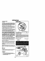
DRILLING
INTO ELECTRICAL
WIRING
GOOD CONDITION.
When using an extension
cord, be sure to use one heavy enough to carry the
current your product wilrdraw. An undersized cord
will cause a drop in line voltage resulting in loss of
power and overheating. A wire gage size (A.W.G.)
of at least 16 is recommended
for an extension
32.
cord 100 feet or less in length. A cord exceeding
1O0 feet is not recommended.
If in doubt, use the
next heavier gage. The smaner the gage number,
the heavier the cord.
33,
inspect for and remove all nails from
before dhlling.
34.
DRUGS,
ALCOHOL,
MEDICATION.
Do not
operate tool while under the influence of drugs,
alcohol, or any medication.
35.
When servicing use only identical Craftsman
replacement
part==.
POLARIZIED PLUGS, To reduce the dsk of electric
shock, this tool has a polarized plug (one blade is
wider than the offier). This plug will fit in a peladzed
outlet only one way. If the plug does not fit fully in
the outlet, reverse the plug. If it still does not fit,
contact a qualified electrician to install the proper
outlet. Do not change the plug in any way.
SAVE THESE INSTRUCTIONS.
Review them
frequently and use them to instruct others who
may use this tool. If you loan someone this tool,
loan them these instructions also.
OUTDOOR
USE EXTENSION
CORDS. When
tool is used Outdoors, use only extension cords
suitable for use outdoors. Outdoor approved cords
are marked with the suffix W-A, for example SJTW-A or SJOW-A,
24.
KEEP BITS CLEAN AND SHARP. Sharp bits
minimize stalling and kickback.
KEEP HANDS AWAY FROM DRILLING AREA.
25.
Keep hands away from bits. Do not reach
underneath work while bit is rotating. Do not
attempt to remove material while bit is rotating.
NEVER USE IN AN EXPLOSIVE ATMOSPHERE.
26,
Normal sparking of the motor could ignite fumes.
INSPECT TOOL CORDS PERIODICALLY
and if
IN
WALLS CAN CAUSE DRILL BIT AND CHUCK
TO BECOME
ELECTRICALLY
LIVE, Do not
touch the chuck or metal housing when dnlling
into a wall; grasp only the insulated handle(s)
provided on the tool.
36,
37.
damaged,
have repaired at your nearest Sears
Repair Center. Stay constantly aware of cord
location
Page 3
lumber
OPERATION
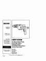
KNOW YOUR ELECTRIC DRILL
Beforeattemptingtouse anytool,familiarizeyourselfwithalloperatingfeatures andsalaryrequirements.
SeeFigure1.
Make sure power supply Is 120 volts, 60 Hz, AC only.
CHUCK
AUXILIARY HANDLE
REVERSE LEVER
CHUCK KEY
CONTROLSELECTOR
SWITCH TRIGGER
BELT CLIP
CHUCK KEY HOLDER
_)
TRUSS HEAD SCREW
Fig+ 1
d
Page 4
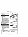
OPERATION
INSTALLING
See F_ure 1,
AUXIUARY
HANDLE
AN AUXILIARY HANDLE IS PACKED WITH YOUR DRILL
FOR EASE OF OPERATION AND TO HELP PREVENT
LOSS OF CONTROL To install, start the screw threads
into the threaded hole in the gear housing and tighten
sac_re_/.
NOTE: For convenience the screw has been trapped inside
the auxiliary handle.
To prevent thread damage and possible losS of control
auxiliary handle should be checked periodically for tightness, CO NOT operate drill with handle loose.
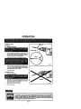
SWITCH
Sea Figure 2.
To turn your dr_[I"ON', depress the switch tdgger, Release
switChthgger to turn your ddll "OFF'.
LOCK-ON
SWITCH TRtGIOER
LOCK.ON
BU'n'ON
Fig. 2
BUI-FON
see Figure 2.
Your drill is equipped with a "lock-on" feature, which is
convenient when continuous drillingfor extended peeqds of
time is required. To k_ck,.on, depress the switch trigger,
push in and hold the lock-on button located on the side of
the handle, then release switch thgger, ReleaSe lock-on
button and your ddll will continue running,
REVERSE (R)
FORWARD (F)
To release the lock, depress the switch trigger and release
it
ff you have the "lock-on" feature engaged during use and
your drill t:ecomes disconnected from power supply, disenga0e the "lock-on" feature immediately,
Fig 3
REVERSIBLE
See Figure 3,
Your dd]l has the feature of being reversible, The direction
o| chuck rotation ia controlled by a lever located above the
switch trigger. With your ddll hold in normat operating position, the direction of rotation lever should be positioned to
the left of the switch for forward (F) drilling operation. The
direction of rotation is in reverse (R) when the lever is to the
right _t the sw_t_h,
THE DESIGN OF THE SWITCH WILL NOT pERMIT
CHANGING THE DIRECTION OF ROTATION WHILE THE
DIR_LL I_ R_NNING. SELEASE THE SWITCH TRIGGER
AND ALLOW THE DRILL TO STOP BEFORE CHANGING
ITS DIRECTION.
NOTE: YOUR DRILL WILL NOT RUN UNLESS THE
SWITCH LEVER IS PUSHED FULLY TO THE LEFT OR
RtGHT.
page 5
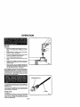
OPERATION
VARIABLE
SPEED
VARIABLE SPEED
CONTROL SELECTOR
S6e Figure 4.
Your ddll has avadable speed control selector designed to
allow operator control and adjustment of speed and torque
limits. The speed and torque of your ddl] can be increased or
decreased by rotating the variable speed control selector in
the direction of the arrows shown in figure 4.
NOTE: Hold your dbll in normal operating position and turn
the variable speed control selector clockwise to increase (+)
the speed and torque of your drill. Turn counterclockwise to
decrease (-) the speed and torque of your drill.
If you desire to lock the switch on at a given speed, depress
the switch trigger, push in and hold the lock-on button, and
release the switch tdgger. Next. adjust the variable speed
control selector until the desired speed is roached.
NOTE: IF THE VARIABLE SPEED CONTROL SELECTOR
IS FULLY TURNED IN THE COUNTERCLOCKWISE
DIRECTION (ZERO SEI"FING) YOUR DRILL MAY NOT RUN.
IF YOU DESIRE NOT TO USE THE VARIABLE SPEED
CONTROL SELECTOR, TURN IT IN THE FULL CLOCKWISE DIRECTION. THIS WILL ALLOW THE SPEED OF
YOUR DRILL TO BE FULLY CONTROLLED BY THE
AMOUNT OF SWITCH TRIGGER DEPRESSION.
Avoid running your drill at lowspeeds for extended periods of
time. Running at low speeds under constant usage may
cause your drill to become overheated. If this occurs, cool
your drill by running it without a load and at full speed.
TO DECREASE SPEED (-)
TO INCREASE SPEED (+)
EXTENSION
Fig. 4
CORDS
The use of any extension cord willcause some loss of power.
TO keep the loss to a minimum and to prevent tool overheating, follow the recommended cord sizes on the chart below.
When tool is used outdoors, use only extension cords suitable for outdoor use and so marked. Extension cords are
available at Sears Retail Stoles.
Extension Cord Length
The following guidelines may he used in determining correct
speed for vadous applications:
Wire Size A.W.G.
0-25 Feet
18
25-100 Feet
16
LOW speed is ideal when minimum speed and power is
required. For example: starting holes without center punching,driving screws, mixing paint, and drilling in ceramics.
MEDIUM speed is suitable for drillinghard metals, plastics,
and ]arnloates.
HIGH speed produces best results when maximum power is
required. For example: drilling in wood; solt metals such as
aluminum, brass, and copper; and when using ditving accessodes.
SLOTS
BELT CLIP
See Figure 5.
For added convenience, a beltclip has been packed with your
drill. It fits on the gear housing as shown in figure 5.
GEAR HOUSING
TO INSTALL
See Figure 5+
1, Align tabs on beit clip with slots in gear housing,
2, Insert tha truss heed screw provided throughbelt clip and
into threaded hole in gear housing.
3. Tighten screw securely.
TRUSS HEAD SCREW
TABS
Fig. 5
Page 6
OPERATION
TO INSTALL
See Figure 6.
BITS
DRILL BIT
1.
UNPLUG YOUR DRILL.
2,
Open or close the chuck jaws to a point where the
opening is slightly la_er than the drill bit you intend to
use. Also, raise the front of your drillslightlyto keep the
drill bits from fallLngout of the chuck jaws.
3.
Insert drill bit into chuck the full length ol the jaws.
4.
Using the chuck hey provided, place chuck key in each
of the three holes and tighten the chuck jaws securely
on dritl bit. DO NOT USE A WRENCH TO TIGHTEN
OR LOOSEN THE CHUCK JAWS.
5.
Remove chuck key.
Fig, 6
TO REMOVE BITS
1, UNPLUGYOUR DRILL.
2.
Using the chuck key prOdded, loosen the chuck jaws
from drillbit. DO NOT USE A WRENCH TO TIGHTEN
OR LOOSEN THE CHUCK JAWS,
3,
Remove drill bit from chuck jaws.
4,
Remove chuck key+
The operation o7 any drill can result in foreign objects being thrown Into your eyes, which
can result in severe eye damage, Before beginning power tool operation, always wear safety
goggles or safety glasses with side shields a_d a full face shield when needed. We
recommend Wide Vision Safety Mask for use over eyeglasses or standard safety glasses
with side shields, available at Sears Retail Stores.
Page 7
OPERATION
DRILLING
See Rgure 8.
1.
Depress and release the switch trigger to be sure your
ddli is in "Off" position before connecting if to power
supply.
2.
Check fhe direation of rotatton lever tor corTectsatting
(ton_vardor reverse). See Figure 3.
3.
Secure the material fo be drilled in a viseor wit hclamps
fo keep it from turning as the dd]l bit rotates.
4.
Plug your dri]l into power supply source.
5
Hold your drill firmly and place the bit al the point to be
drilled.
6.
Dapressfheswitchtdggertostartyourddll. Donotlock
the switch"On" forjobswhere yourddll may need to be
stopped suddenly.
7,
Move the drill bit into the workplece applying only
enough pressure to keep the bit cutting. DO not force
your drillor apply side pressure to elongate a hole. Let
your drill and bit do the work. See Figure 8,
When drilling hard, smooth surfaces use a center punch to
mark the desired hole location, This will prevent the drill bit
from slippingoff center as the hole is started, However, the
variable speed feature allows stadlng holes without center
punching if desired. TO accomplish this, operate your drill at
a low speed until the hole is started.
When drilling metlds use a 5ghtoilon the drillbit to keepit from
overheating. The oilwill prolong the life ofthe bitand increase
the drilling action.
If the bit jams in the workpiece or if your drill stalls, stop the
foolimmediately. Remove the bit from the workpiece and defermine the reason for jarmning.
POWER
CORD
See Figure 9.
Your new ddll has an 8' powercord that stays soft and flexible
in cold weather. The plug design is shaped so that it won't
snag on yourwork during use. A molded cord clip on the ptug
makes cord storage easier.
Page 8
Fig. 9
OPERATION
CHUCK
REMOVAL
See Figures 10, If, and 12.
The chuck must be removed in order to use some accessodes. TO remove;
1.
UNPLUG YOUR DRILL.
2.
3.
Close the chuck jaws.
Line up hole in spindle with slot in gear housing and
insert a 1/8 in. diameter nail or pin into hole in spindle
shaft.
Insert chuck key into chuck and tap sharply with a
mal]ot in a clockwise direction. See Figure 10. This will
loosen the screw in the chuck for easy removal.
Open the _k
i_ws end remove the chuck screw by
turning it in a cloCkwise direction. See Figure 11.
NOTS: The chuck screw has left hand threads.
thsed chuck key into chuck and tap sharply with a
realist in a counterclockwise direction. This will loosen
the chuck on the spindte, ft can now be unscrewed by
hand, See Figure 12.
UnloCkspindle by removing nail or pin from slotin gear
housing.
4.
5.
6.
7.
Fig. 10
The chuck m_y at limes become Loose on the spthdis and
develop a wobble. Also, the chuck screw may become loose
causing the chuck jaws to bind and prevent them from
closing. TO tighten, follow these steps:
1. UNPLUG YOUR DRILL.
2.
3.
4.
5.
6.
FI
Openthechuckisws.
Line up hole in spindle with slot in gear housing and
insed a 1/8 in. diameter nail or pin into hole in spindle
shaft,
thsed chuck key Lnto chuck and tap sharply with a
m&_t in _ ctockwi_ _rection. This will tighten the
chuck on the spindle.
Tighten the chuck screw. NOTE: The chuck screw
has left hand threads.
UnloCk spindle by removing nail or pin from slot in
gear housing.
THE FOLLOWING RECOMMENDED ACCESSORIES
TIME THIS MANUAL WAS PRINTED.
ARE CURRENT AND WERE AVAILABLE AT THE
Hole Saws 1-1/2 in. Max.
Doweling Jig (Item NO. 4186)
Industrial Chuck (Item No, 20986 )
High Speed Bits (For wood or metal) 3/8 in. Max.
Masonry Bits
1/2 in. Max.
Wood Boring Bits
1-1/4 in. Max.
_The
use of attachments
or accessories
Page
g
not
listed
aboVe
might
be hazardous.
11
MAINTENANCE
GENERAL
Only the parts shown on parts list, page 11, are intended to
he repaired or replaCed by the customer. All other pads
represent an important pad of the double insulation system
and should be serviced only by a qualified Sears service
technician,
Avoid using solvents when cleaning plastic parts. Most
plastics are susceptible to vadous typos of commercial SOlvents and may be damaged by thair use. Use clean cloths
to remove dirt, carbon duet, etc.
When electric tools are used on fiberglass boats, sports
cars, wallboard, spackling compounds, or plaster, it has
been found that they ara subject to accelerated wear and
passible premature faikJre, as the fiberglass chips and
grlndings are highly abrasive to bearings, brushes,
COmmUtator,etc. Consequently it is not recommended that
this too_be used for extended _nt on any fiberglass material,
wallboard, spacking compounds, or piaster. During any
use On fiberglass it is extremely important that the tooJ is
cleaned frequently by blowing with an air jet,
LUBRICATION
All ofthe bearings in this tool are hibdcated with a sufficientamount of high grade lubricant for the life of the unit under norma;
operating conditions, Therefore. no further lubricationis required.
CRAFTSMAN
CHUCK
KEY
HOLDER
1,
F_rmaiaopbyforcingendwithroundholasthroughslotledbele0noppositeend.
2.
Place the lOOpor'el the cord and pull it tight. See Figure 14.
3,
Mountthechuckkeybytosertingthegearedendthroughtheholelntheholder,
in the small hole. See Figure 15.
See Figure13.
Largekeysintbeiargerhoia,
smetlerkeys
CORD
Fig. 13
Rg. 14
Page
10
Rg. 15
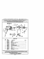
CRAFTSMAN
I
3/8 INCH
INDUSTRIAL
ELECTRIC
DRILL
- MODEL
NUMBER
315.271410
The
number willbe
found on
a plate
to the motor
housing.
Always
mention
the model
in allmodel
correspondence
regarding
your
3i8 attached
INCH ELECTRIC
DRILL
or when
ordedng
repair
pads, number
SEE BACK
PAGE
FOR
PARTS
ORDERING
1
I
INSTRUCTIONS
SEE NOTE"A"
4
5
PARTS LIST
Key
No.
1
2
3
4
5
6
7
8
9
10
11
12
13
14
15
Part
Number
969047-001
969048o001
931055-827
968702-019
973102-001
616478-003
617096-002
969062-001
969038-204
969332-001
621608-000
706382-824
972895-00"2
969046-001
969055-001
612547-747
DescrlpUon
Quan.
Data Plate .............................................................................................
1
Logo Plate .............................................................................................
1
Washer ..................................................................................................
1
" Screw (#8-16 x 1-1/'2 in. Pan Hd.) ........................................................
3
Chuck (Item No. 20986) ........................................................................
1
Screw (Special) .....................................................................................
1
Retaining Ring ......................................................................................
1
Chuck Key (Item NO. 2055) ..................................................................
1
Gear Housing with Beating ...................................................................
1
intermediate Gear and Pinion Assembly .............................................. 1
Spacer ...................................................................................................
1
Washer ..................................................................................................
1
AuxilianJ Handle ....................................................................................
1
Belt Clip .................................................................................................
1
* Screw (#3/6-24 x 5/8 in. Tress Hd.) ...................................................... 1
Owner's Manual
NOTE: "A" - The assembly shown represents an important part of the Double Insulated System. To avoid the
possibility of alteration or damage to the System, service should be performed by your nearest Sears
Repair Center. Contact your nearest Sears Retail Store.
• Standard Hardware Item - May Be Purchased Locally
** Available From Division 98 -- Source 980,00
Page 11
For repairof major brand appliancesin your own home...
no matter who made it, no matterwho sold it!
1-800-4-MY-HOME
s" Anytime,day or night
{1-800-469-4663)
www,sears,com
To bringin productssuch as vacuums,lawn equipmentand electronics
for repair,call for the locationof yournearest Sears Parts & Repair Center.
1-800-488-1222
Anytime,day or night
www.sears.com
For the replacementparts,accessoriesand owner'smanuals
that you need to do-it-yourself, call Sears PartsDIrect SM !
1-800-366-PART
(1-800-368-7278)
8a.m.-11p.m.CST.
7 days a week
www.sears.com/partsdirect
To purchaseor inquireabout a Sears ServiceAgreement:
1-800-827-6655
7 a.m. - 5 p.m. CST, Mon.- Sat.
Para pedir serviciode reparaclbna dornicilio,
y para ordenar piezas con entrega a domicilio:
t -888-SU-HOGAR _
(1°888-784*6427)
_ Reg_temd Trademark / _
0 _
I:k_eb_ck e,;_ CO.
® MarCh _adl
T_
AuCanada pour serviceen fran(;ais:
1-8T/-LE-FOYER_
(1-877-533-6937)
ol _rs,
_
=_d CO
I _ Marca de F4bdcm de Sears, Rcebuck arid Co