1
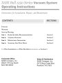
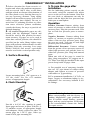
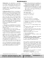
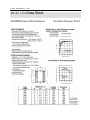
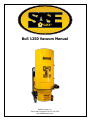
SASE Bull 1250 Vacuum Manual SASE Company, Inc. Phone 800.522.2606 or Fax 877.762.0748 www.SASECompany.com SASE Corporate Office 26423 79th Ave South Kent, WA 98032-7321 1.800.522.2606 (P) 1.877.762.0748 (F) www.SASECompany.com [email protected] Congratulations on your decision to get the Power of SASE behind you! SASE is committed to excellence, excellence in the quality of products we sell and excellence in service and support after the sale. It is important to us that your business continues to succeed and grow, and we know that the right products, service and support can have a great impact on your bottom line. SASE has made great strides in the concrete preparation and polishing industry over the years. With a 40,000 square foot distribution and service facility in Seattle, a 22,000 square foot distribution and service facility in Knoxville, and local sales and technical support representatives throughout the United States, SASE is able to provide unsurpassed service and technical support for the contractor. At SASE we engineer and manufacture our own equipment, which allows us to be in control of the quality of the equipment we sell. SASE offers a complete line of concrete preparation and polishing equipment, our newest introduction being our new line of PDG planetary diamond grinders, which is setting a new standard for the concrete grinding and polishing industry. SASE is also the leader in diamond tooling technology. We look forward to a long and prosperous partnership with you! Thank you again for choosing SASE. You won’t regret having the Power of SASE behind your company! Sincerely, SASE Company, Inc. Jim Weder President SASE Company Inc. Equipment Safety Policy Statement SASE Company, Inc. is adamant that safety is one of the highest priorities for both our employees and customers. When considering set-up and operation of any piece of equipment supplied, manufactured, distributed, rented or serviced by SASE Company, Inc., the safety and protection of people should always be a top priority. All customers and employees should follow all OSHA and local safety standards, requirements and regulations. The use of the following safety equipments are both recommended and required when operating any piece of equipment supplied, manufactured, distributed, rented or serviced by SASE Company, Inc. OSHA approved/certified eye protection (safety glasses). OSHA approved/certified hearing and ear protection. OSHA approved/certified foot protection (steel toed boots). OSHA approved/certified respirator or breathing device. OSHA approved head protection (hard hat). Proper protective work gloves. Proper protective clothing limiting skin exposure. (The list is not meant to be all inclusive. Please exercise sound judgments during operation.) The work area must always have proper ventilation to minimize the health and safety risks of propane and gasoline emissions and airborne dust. All SASE Company Equipment is engineered, designed and provided with dust control shrouds and vacuum ports. It is strongly recommended that an approved dust containment system be connected to and used in conjunction with all SASE Company equipment during operational use. SASE Company supplies, distributes, rents and services dust control systems with HEPA filtration. Extreme caution must be exercised at all times when electrical power is considered. All SASE employees are prohibited from working on or hard wiring our equipments to any power source that has not been provided by SASE Company Inc. Any such work must be performed by a certified electrical technician. No SASE employee is permitted or authorized to work on, operate, or connect our equipment or equipment belonging to our customers to an electrical source that does not meet OSHA approved specifications. There are no exceptions to this policy! SASE Company, Inc. also strongly recommends that only certified electricians be permitted to deal with or manipulate electrical power sources within our customers’ facilities or on their job-sites. Finally, we at SASE Company, Inc. cannot stress enough the importance of following general safety practices, the utilization of appropriate safety equipment and the application of common sense when operating equipment supplied, manufactured, distributed, rented or serviced by SASE Company, Inc. (JJL 07/2010) both on the job-site and in the field. S A S E C O M P A N Y , I N C . FOREWORD T o achieve the safe installation and operation of your new BULL 1250 vacuum system, we urge you to become familiar with the information in this manual. The BULL 1250 industrial vacuum cleaning system is designed to provide continuous 24 hours per day operation. The mechanical and electrical components are of a robust nature and will provide long life with minimal maintenance even under severe conditions. This manual describes the installation and preventative care requirements to ensure their maximum life and to provide virtually trouble-free operation for years ahead. This manual is prepared in five (5) general Sections: Section 1: Health and Safety Recommendations Section 2: An Introduction to the QV and its Capabilities Section 3: Maintenance Instructions Section 4: Accessory Data Sheets Section 5: Service and Maintenance Instructions for the blower Replacement Parts Lists, if applicable, can be found within the individual sections pertaining to that item. Past experience indicates that the majority of part replacements and repairs occur due to misuse or carelessness by personnel not qualified to operate and service this equipment. Observance of the instructions in this manual will minimize references to those Sections pertaining to Repair and Replacement. S A S E C O M P A N Y , I N C . START-UP INSTRUCTIONS WARNING! Failure to follow these simple start-up instructions could result in the failure of your new BULL 1250 Industrial Vacuum Cleaner. Although your new BULL 1250 Industrial Vacuum System was factory run tested before shipping, we strongly recommend that you follow the start-up procedure described below. Start-Up Open the access door on your new BULL 1250 and inspect all filter bags to assure they are properly seated and did not come loose during shipment. Or remove the dirt can and look at the tube sheet from below; all the filters should be installed neatly and evenly. If the filters are not seated tightly dust will leak by them. Leave the access door open. Place an amp probe on one line of the electrical connections, and “bump” the motor. You should get air blowing from the discharge silencer. If you note a vacuum at the discharge silencer, reverse the motor direction. Start the unit, and allow it to run several minutes with the access door open. Listen for any “unusual” sounds. The system should run quietly, smoothly, and cool. After a few minutes, feel the casing of the vacuum pump for “hot spots”. It should feel uniformly slightly warm. With the motor still running, connect a hose into the system, and close the access door. While watching the amp probe reading, slowly close off the end of the hose with your hand. The amperage should climb to within 90 - 95% of the motor’s name plate full amperage rating for the voltage at which you are operating. S A S E C O M P A N Y , I N C . Please note that not all portable units are provided with vacuum relief valves. If your machine is not equipped with this device If the motor amperage holds at or slightly below the recommended full load with all hoses fully closed, and air is bleeding in through the vacuum relief valves, then unit is ready for full operation. NOTE: The vacuum relief valves are factory set to the proper vacuum relief setting before shipping. If they do not open, or if the amperage exceeds the nameplate motor amperage, shut the unit off and contact the factory IMMEDIATELY. S A S E C O M P A N Y , 1 I N C . Section Health and Safety Recommendations The Infor mation Contained In This Section Can Help Prevent Serious Personal Injur y. PLEASE READ THIS SECTION CAREFULLY BEFORE OPERATING OR SERVICING THIS EQUIPMENT. T his section outlines some of the health and safety issues that must be acknowledged when operating or servicing your BULL 1250 industrial vacuum cleaning system. It is important that plant operators are made aware of the responsibility incumbent on them to take all necessary precautions to ensure their health and safety, and that plant authorities implement the procedures necessary toward this end. We strongly advise that you, the customer, add to, and tailor, these safety recommendations to suit your own particular working and operating environment. Explosive Dust Please contact us if your process changes so we may help evaluate your risk. The operators of this equipment must always be aware of the physical and chemical properties of the dust particles being collected. A surprising number of dusts are flammable or prone to explosion when mixed with air as we find with a filter receiver application. Materials or processes presenting such hazards MUST be identified by the customer so that specific safety features can be built into the separator. S A S E C O M P A N Y , I N C . The customer must also be alert to any changes in the dust material or process. If a new process is introduced after the installation of the vacuum system which changes the composition, quantity, or most especially the chemical type of material being introduced into the vacuum system, this may greatly increase the chance of explosion and fire. If your process is to be changed, or if you have any concerns, we suggest you contact us to see how we can assist you to ensure that the operation of your BULL 1250 industrial vacuum cleaning system is as safe as possible. Isolate Electrical Before Maintenance DO NOT ATTEMPT ANY MAINTENANCE WORK UNTIL ALL ELECTRICAL GEAR HAS BEEN ISOLATED. Isolate all electrical before removing any guards, covers or accessories before beginning any maintenance or repair work. Always lock out the main system blower disconnect before opening any inspection door on any separator or filter receiver. Before re-connecting the electrical supply, ensure that all guards, covers and accessories are correctly replaced. Observe Accessories Safety Requirements All the major equipment, including the blowers and all the separators, have accessory items attached and working in conjunction with them. The operators should be familiar with the safety and operating instructions of each accessory component. NOTE: MANY ACCESSORIES ARE AUTOMATICALLY CONTROLLED AND MAY STARTUP AT ANY TIME! S A S E C O M P A N Y , I N C . Implement Measures to Handle Respirable Dust Operators must be fitted with appropriate respirators and must wear protective clothing if handling dust that may be irritating or even toxic. We recommend that the MSDS’s for each of the dusts to be handled by the vacuum system be included in this manual, and that specific measures to handle problem materials be clearly identified in those sections of this manual where the operator is exposed to these dusts; i.e. filter bag replacement, etc. Use Suitable Electrical Warning Notices Company specific lockout and safety procedures should be inserted in this section. Do NOT leave electrical gear live and unattended without a suitable warning notice. Distinctive warning notices must be provided for posting in a conspicuous position to any piece of electrical equipment or machinery on which maintenance is being carried out, and which, for any reason whatsoever, is liable to be left unattended while in a live condition. Use CAUTION When Using the Hoses BULL 1250 vacuum systems use blowers that develop very high vacuum conditions which can be dangerous if caution is not observed. DO NOT PUT THE END OF THE HOSE AGAINST YOUR SKIN OR CLOTHES OR THOSE OF OTHERS! Remove the hose from the inlet valve to dislodge materials that plug the end of tools. S A S E C O M P A N Y , 2 I N C . Section A System Overview This section provides an introduction to the BULL 1250 industrial vacuum, how it works, its capabilities and its limitations. An Introduction to the DVT Vacuum System The BULL 1250 vacuum system is essentially an open-source material pneumatic conveying system; that is, material entrained at the nozzle of the hose is conveyed by air through a hose and possibly through a network of piping. At the business end of the system, in simplest terms, the material is removed or "separated" from the air stream, with the waste material being collected in the dirt can for disposal or reuse, and with the cleaned air being drawn through the vacuum pump then exhausted. The BULL 1250 vacuum system is primarily designed to handle super-fine powders like carbon black, talc, pigments, oxides, and plastic compounding dusts. It is the only vacuum system in its class to offer industrial class suction with a standard filtration system that will handle super-fine powders without modification. It is designed run continuously with these “problem powders” without having to shake the filters until the dirt can is filled. Plus, the BULL 1250 features a continuous duty vacuum pump that actually pulls harder the more the operator puts material in the hose. This means that the BULL 1250 vacuum system can pickup material spills up to three times faster than competitive units. With the addition of an optional vacuum relief valve, the BULL 1250 may be connected to short steel tubing networks to provide localized vacuum service to inlet valves located on mezzanines, platforms, or other spots where vacuum service is required, but where it is awkward to locate the BULL 1250 itself. Please refer to the dimensional drawing on the last page of this section. It shows that the main components of the BULL 1250 are: S A S E C O M P A N Y , I N C . 1. The ALL STAR Regenerative Vacuum Producer 2. The 20” Filter Separator 3. The Inline Safety Filter The air stream in the BULL 1250 system is cleaned three times before it is exhausted: first, inside the filter separator there is a special cyclonic separation chamber in the lower section that spins out most (95%) of the material; second, there is a high performance filtration section that removes 99.9% of material larger that 0.4 microns; and finally, there is an in-line filter that captures any leftover dust and provides “back-up” protection to the vacuum producer, workers, and to the environment if the primary filters break or do not get installed properly. The BULL 1250 has a material storage capacity of 29.9 US Gallons (3.94 cubic feet). System Capabilities and Limitations The BULL 1250 vacuum producer will support the following: • • • up to four (4) simultaneous operators each with a 1.25" ID hose up to 25 ft. long up to two (2) simultaneous operators each with a 1.5" ID hose up to 50 ft. long or one (1) operator with a 2.0 inch ID hose up to 50 ft. long. IMPORTANT NOTE! The vacuum producer provides industrial-strength vacuum power to the operators, so the system is mostly forgiving of plugs, but all vacuum systems MUST have an air/material mix to work; this is why we talk of the system as a pneumatic conveyor. It is essential that operators be trained to introduce air into the hose with the material at a reasonable rate. Without conveying air, material will NOT move! The BULL 1250 system is designed to handle almost anything that will fit though the vacuum hoses. However, the BULL 1250 is not design to handle liquids directly. If the filters get wet, then are coated with fine powders, the filters will “blind”. The filters must them be laundered (if facilities exist), or replaced. Please contact your representative if you wish to pick up liquids. S A S E C O M P A N Y , I N C . As well, this system is not suitable for use with highly explosive powders, nor can it be modified for that use. It is fully grounded, but cannot be explosion vented. S A S E C O M P A N Y , I N C . Before commissioning, open access door and check to ensure all bags are firmly secured to the lower bag plate. The top of the bags are attached to the top of the filter housing by use of small hooks and the bags must not be loose or out of place. NOTE: A loose or unsecured bag will allow product to pass through the filter separator and will plug the in-line filter. The filter bags should be shaken at least daily, preferably after each use. To shake filter bags, simply open the bag house door and shake the filter assembly arm swiftly back and forth. This rapid movement will dislodge particles on the inside of the filter bag surfaces and drop them into the dust can. NOTE: The unit must be OFF in order to shake the filters. If the filters are to be replaced, please replace them ALL at once, or they will be a constant source of frustration. Filter Bag Maintenance The following is a recommended program of preventative maintenance: 1. Check that the filters are seated properly and that they do not appear to be leaking WEEKLY. There should be NO appreciable or visible dust inside the service access door. 2. Replace ALL the filters if wear points or holes are noticed. 3. If the secondary filter cartridge becomes plugged rapidly, check for holes in the primary filter bags, or upgrade the primary filter material to a more efficient type. 4. Replace the secondary filter cartridge when the manometer reads higher than 12” WG. Operators must be outfitted with appropriate respirators and must wear protective clothing if handling dust that may be irritating or toxic. Removing Filter Bags To change the filter bags, remove each bag from the S - hooks on the filter shaker assembly inside the tank at the top. Squeeze the spring cuff at the bottom of the bag compressing the snap ring into a “U” shape, and remove from the bag plate hole. S A S E C O M P A N Y , I N C . Installing New Filter Bags The most common installation mistake is to release the cuff lower than it should be. The groove in the bag cuff matches the hole size exactly. Attach the grommet in the bag to the S - hooks on the filter shaker assembly inside the tank at the top. Grasp the spring cuff at the bottom of the bag and compress into a “U” shape. Insert into the proper hole in the bag plate, and release the bag bottom, assuring the “groove” in the bag cuff is centered in the bag plate hole. After installing all the filters, check the installation from below; all the filters should be neatly and evenly seated. WARNING: Failure to assure proper seating of the bag in the bag plate will allow material leakage. Filter Bag Specification The filter bags supplied with this system are: Material: P84 Composite with snap band Quantity: 14 Length DVR60, DVR85 40 3/8” Length DVR60L, DVR85L 32” Bag Plate Hole Size 5” Grounding Req’d: Yes Please see Section 4 of this manual for a technical description of the P84 filtration media supplied standard with this machine. The Inline Filter The inline filter supplied with this unit will help prevent damage to the exhauster in case of failure of a primary filter bags. There is a differential pressure gauge connected across the inline filter which indicates the condition of this filter. During normal operation, this manometer should read approximately 2 - 3” of water differential pressure (WG), slightly higher if HEPA type high efficiency filter elements are installed. BULLETIN NO. Magnehelic ® A-27 Differential Pressure Gage O P E R AT I N G I N S T R U C T I O N S SPECIFICATIONS Dimensions: 4-3/4 dia. x 2-3/16 deep. Weight: 1 lb. 2 oz. Finished: Baked dark gray enamel. Connections: 1/8 NPT high and low pressure taps, duplicated, one pair side and one pair back. Accuracy: Plus or minus 2% of full scale, at 70°F. (Model 2000-0, 3%; 2000-00, 4%). Pressure Rating: 15 PSI (0,35 bar) Ambient Temperature Range: 20° to 140°F (-7 to 60°C). Standard gage accessories include two 1/8 NPT plugs for duplicate pressure taps, two 1/8 NPT pipe thread to rubber tubing adapters, and three flush mounting adapters with screws. Caution: For use with air or compatible gases only. For repeated over-ranging or high cycle rates, contact factory. Not for use with Hydrogen gas. Dangerous reactions will occur. Ø4-1/8 [104.78] BOLT CIRCLE FOR PANEL MOUNTING 120° APART 1/8 NPT HIGH PRESSURE 1-1/4 1-3/4 [31.75] [44.45] 1/2 [12.70] 1/8 NPT HIGH PRESSURE 1/8 NPT LOW PRESSURE 1/8 NPT LOW PRESSURE 11/16 [17.46] 7/16 [11.11] 1-11/16 [42.86] DWYER INSTRUMENTS, INC. P.O. BOX 373 • MICHIGAN CITY, INDIANA 46361 U.S.A. Ø4-3/4 [120.65] 1/2 [12.70] Phone: 219/879-8000 www.dwyer-inst.com Fax: 219/872-9057 e-mail: [email protected] Lit-by-Fax: 888/891-4963 MAGNEHELIC® INSTALLATION 1.Select a location free from excessive vibration and where the ambient temperature will not exceed 140°F. Also, avoid direct sunlight which accelerates discoloration of the clear plastic cover. Sensing lines my be run any necessary distance. Long tubing lengths will not affect accuracy but will increase response time slightly. Do not restrict lines. If pulsating pressures or vibration cause excessive pointer oscillation, consult the factory for ways to provide additional damping. 2. All standard Magnehelic gages are calibrated with the diaphragm vertical and should be used in that position for maximum accuracy. If gages are to be used in other than vertical position, this should be specified on the order. Many higher range gages will perform within tolerance in other positions with only rezeroing. Low range Model 2000-00 and metric equivalents must be used in the vertical position only. 3. Surface Mounting Locate mounting holes, 120° apart on a 41/8⬙ dia. circle. Use No. 6-32 machine screws of appropriate length. 4. Flush Mounting Provide a 4-9/16⬙ dia. opening in panel. Insert gage and secure in place with No. 632 machine screws of appropriate length, with adapters, firmly secured in place. To mount gage on 1-1/4⬙-2⬙ pipe, order optional A-610 pipe mounting kit. 5. To zero the gage after installation Set the indicating pointer exactly on the zero mark, using the external zero adjust screw on the cover at the bottom. Note that the zero check or adjustment can only be made with the high and low pressure taps both open to atmosphere. Operation Positive Pressure:Connect tubing from source of pressure to either of the two high pressure ports. Plug the port not used. Vent one or both low pressure ports to atmosphere. Negative Pressure: Connect tubing from source of vacuum or negative pressure to either of the two low pressure ports. Plug the port not used. Vent one or both high pressure ports to atmosphere. Differential Pressure: Connect tubing from the greater of two pressure sources to either high pressure port and the lower to either low pressure port. Plug both unused ports. When one side of the gage is vented in dirty, dusty atmosphere, we suggest an A331 Filter Vent Plug be installed in the open port to keep inside of gage clean. A. For portable use of temporary installation use 1/8⬙ pipe thread to rubber tubing adapter and connect to source of pressure with rubber or Tygon tubing. B. For permanent installation, 1/4⬙ O.D., or larger, copper or aluminum tubing is recommended. See accessory bulletin S-101 for fittings. Ordering Instructions: When corresponding with the factory regarding Magnehelic® gage problems, be sure to include model number, pressure range, and any special options. Field repair is not recommended; contact the factory for repair service. S A S E C O M P A N Y , I N C . up to seal on the tank flange gasket. Do not over-tighten, only a slight pressure is required to form an airtight seal. NOTE: Make sure the handle on the dirt can is pointing out away from the unit or the can will not seal. To remove the dust can simply rotate the handle upward to lower the dust can and pull the assembly out of the separator. NOTE: Dispose of waste material in accordance with local environmental codes. Vacuum Seals If you experience a “lack of suction”, almost certainly there is a leak in a seal somewhere in the system. The following is a short list of common fail points: 1. Check the door seals. If air is leaking in through these seals, dust will normally collect on the inside surface of the door showing the exact location of the leak. Sometimes, running your hands around the door frame will allow you to locate the leak. Either way, replace the seals as required. 2. DO NOT over-tighten the door latches! Almost certainly that will cause more problems than it fixes. 3. Check the dust can gaskets. If they are torn or worn, please replace them. 4. Check the dust can lifting mechanism. This mechanism sometimes loosens with vibration and must be re-adjusted. 5. DO NOT over-tighten the lifting mechanism. The dust can flange need only depress the gasket. The seal will form when the system is turned on. Over-tightening the lifting mechanism will only lead to premature wear of the gasket and will cause constant problems. 6. If the unit is connected to a central vacuum piping system, check the integrity of the seals there. Of particular importance, check the seals at each inlet valve as these valves often get knocked and no longer seat well. 7. Check the hoses for leaks. A hose covered in duct tape is a sure indicator that the hoses should be replaced. MAINTENANCE Caution: If bezel binds when installing, lubricate threads sparingly with light oil or molybdenum disulphide compound. Warning: Attempted field repair may void your warrenty. Recalibration or repair by the user is not recommended. For best results, return gage to the factory. Ship prepaid to: Dwyer Instruments, Inc. Attn: Repair Dept. 102 Indiana Highway 212 Michigan City, IN 46360 Maintenance: No lubrication or periodic servicing is required. Keep case exterior and cover clean. Occasionally disconnect pressure lines to vent both sides of gage to atmosphere and re-zero. Optional vent valves, (bulletin S-101), should be used in permanent installations. Calibration Check: Select a second gage or manometer of known accuracy and in an appropriate range. Using short lengths of rubber or vinyl tubing, connect the high pressure side of the Magnehelic gage and the test gage to two legs of a tee. Very slowly apply pressure through the third leg. Allow a few seconds for pressure to equalize, fluid to drain, etc., and compare readings. If accuracy unacceptable, gage may be returned to factory for recalibration. To calibrate in the field, use the following procedure. Calibration: 1. With gage case, held firmly, loosen bezel, by turning counterclockwise. To avoid damage, a canvas strap wrench or similar tool should be used. 2. Lift out plastic cover and “O” ring. 3. Remove scale screws and scale assembly. Be careful not to damage pointer. 4. The calibration is changed by moving the clamp. Loosen the clamp screw(s) and move slightly toward the helix if gage is reading high, and away if reading low. Tighten clamp screw and install scale assembly. 5. Place cover and O-ring in position. Make sure the hex shaft on inside of cover is properly engaged in zero adjust screw. 6. Secure cover in place by screwing bezel down snug. Note that the area under the cover is pressurized in operation and therefore gage will leak if not properly tightened. 7. Zero gage and compare to test instrument. Make further adjustments as necessary. ©Copyright 2001 Dwyer Instruments, Inc. Trouble Shooting Tips: •Gage won’t indicate or is sluggish. 1. Duplicate pressure port not plugged. 2. Diaphragm ruptured due to overpressure. 3. Fittings or sensing lines blocked, pinched, or leaking. 4. Cover loose or “O”ring damaged, missing. 5. Pressure sensor, (static tips, Pitot tube, etc.) improperly located. 6. Ambient temperature too low. For operation below 20°F, order gage with low temperature, (LT) option. •Pointer stuck-gage can’t be zeroed. 1. Scale touching pointer. 2. Spring/magnet assembly shifted and touching helix. 3. Metallic particles clinging to magnet and interfering with helix movement. 4. Cover zero adjust shaft broken or not properly engaged in adjusting screw. We generally recommend that gages needing repair be returned to the factory. Parts used in various sub-assemblies vary from one range of gage to another, and use of incorrect components may cause improper operation. After receipt and inspection, we will be happy to quote repair costs before proceeding. Consult factory for assistance on unusual applications or conditions. Use with air or compatible gases only. Printed in U.S.A. 4/01 DWYER INSTRUMENTS, INC. P.O. BOX 373 • MICHIGAN CITY, INDIANA 46361 U.S.A. FR# 12-440212-00 Rev. 3 Phone: 219/879-8000 www.dwyer-inst.com Fax: 219/872-9057 e-mail: [email protected] Lit-by-Fax: 888/891-4963 S A S E C O M P A N Y , I N C . BULL 1250 Data Sheet SOLBERG Inline Filter Element Re-Order Number 234 P