1
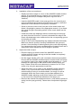
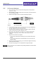
Operating Instructions
METACAP Spray Gun D/A
Operating Instructions
General Information
METACAP Spray Gun D/A
Table of Contents
1-2
1
1.1
1.2
General Information...........................................................................1-3
Introduction ..........................................................................................1-3
Scope of Supply of the METACAP Spray Gun D/A.............................1-3
2
2.1
2.2
Description of the METACAP Spray Gun D/A.................................2-4
Technical Data .....................................................................................2-4
Identification.........................................................................................2-4
3
3.1
3.2
Use ......................................................................................................3-5
Intended Use .......................................................................................3-5
Incorrect Use .......................................................................................3-5
4
Warranty .............................................................................................4-6
5
5.1
5.2
5.3
5.4
General Safety Instructions ..............................................................5-7
Risk of Fire and Explosions .................................................................5-7
Personal Protection .............................................................................5-8
Noise Level ..........................................................................................5-9
Instruction of the Personnel .................................................................5-9
6
6.1
6.2
6.3
6.4
Description, Structure and Functioning........................................6-10
Description .........................................................................................6-10
Structure of the METACAP Spray Gun D/A ......................................6-11
Spare Parts List for the METACAP Spray Gun D/A ..........................6-12
Functioning ........................................................................................6-13
7
Initial Operation ...............................................................................7-14
8
8.1
8.2
Operating Instructions ....................................................................8-15
Default Settings .................................................................................8-15
Spray Process ...................................................................................8-18
9
9.1
9.2
9.2.1
9.2.2
9.2.3
9.2.4
9.2.5
Maintenance and Care.....................................................................9-19
Cleaning.............................................................................................9-19
Maintenance and Repair....................................................................9-22
Safety Instructions .............................................................................9-22
Check/Replacement of Silencer Ring................................................9-22
Replacement of Nozzle & AKKORD Needle, Adjustment of Initial Air
Input Settings .....................................................................................9-22
(Dis-)Assembly of Nozzle Holder , Replacement of Sealing Ring.....9-24
Air Converter Adjustment...................................................................9-26
10
Troubleshooting Table – METACAP Spray Gun D/A .................10-28
11
11.1
11.2
Cleaning and Disposal ..................................................................11-30
Cleaning...........................................................................................11-30
Disposal ...........................................................................................11-31
12
ATEX ...............................................................................................12-31
13
EC-Declaration of Conformity ......................................................13-32
Version/Edition July 2008
Operating Instructions
General Information
METACAP Spray Gun D/A
1
General Information
1.1
Introduction
It is indispensable for the user of this METACAP Spray Gun D/A to carefully
read the complete contents of this operating manual before using the spray
gun to ensure a safe and correct operation. This operating manual includes
important information concerning the safe and economical use of this spray
gun.
Therefore, always keep this operating manual accessible!
Failure to observe the instructions of this operating manual will render the
manufacturer free of any legal liabilities!
1.2
Scope of Supply of the METACAP Spray Gun D/A
1 METACAP Spray Gun D/A
Item no. 101115
1 cleaning brush, short (see 9.1 Cleaning, page 9-19)
Item no. 30078
1 cleaning brush, long (see 9.1 Cleaning, page 9-19)
Item no. 30077
1 needle cleaning brush (see 9.1 Cleaning, page 9-19)
Item no. 30083
(only for the AKKORD type)
1 mounting bolt for nozzle holder
Item no. 30084
(see 9.2.4 (Dis-)Assembly of Nozzle Holder , page 9-24)
The above mentioned item numbers refer to the spare parts available by
Metacap upon request.
Version/Edition July 2008
1-3
Operating Instructions
Description of the METACAP Spray Gun D/A
METACAP Spray Gun D/A
2
Description of the METACAP Spray Gun D/A
The METACAP Spray Gun D/A was developed for the combined use with
conveying equipment and circulation systems for coating materials and with
METACAP bottom cup sets.
2.1
Technical Data
Hose couplings
Air supply 1/4" outside thread with plug-in nipple
for quick connect coupling NW7, 2 equipped.
Material supply 3/8" outside thread
Maximum
pressure
working Air supply PI 10bar max.
Material pressure 8bar max.
Weight
680g without cup,
Bottom cup set 0.5L - 305g
Bottom cup set 1.0L - 370g
Accessories
Bottom cup sets for 0.5 and 1.0 L
item no. 101115A and 101115B
Recommended
pressure
air 3 – 6 bar for at least 300 L/min of efficient air
supply
The compressed air must be dry and oil-free.
Minimum inner section of the feed pipe: 9mm
Material pressure
The material pressure depends on the coating
material and can be adjusted on the paint delivery
unit (maximum: 8 bar).
When using bottom cup sets, the material
pressure results from the spraying pressure.
2.2
Identification
Note:
The identification was effected according to DIN EN 1953 "Atomising and
Spraying Equipment for Coating Materials– Safety Requirements", section
7.2 "Identification".
The serial number of the spray gun is recorded on the left side of the spray
gun handle, the maximum air pressure and the maximum pressure for the
coating material are indicated on the right side of the spray gun handle.
2-4
Version/Edition July 2008
Operating Instructions
Use
METACAP Spray Gun D/A
3
Use
3.1
Intended Use
The METACAP Spray Gun is exclusively intended for:
3.2
—
the spraying of coating materials (paint, lacquer, stripping agent, oil,
fatty matters and similar substances).
—
the combined use with conveying equipment and circulation systems for
coating materials and with METACAP Bottom Cup Sets.
—
Use only conductive tubing. (more information see 5.1 Risk of Fire and
Explosions)
Incorrect Use
—
Never point the spray beam and/or air jet at living things.
There is a risk of injury.
—
Never exceed the admissible working pressures of the coating device /
of the spray gun.
—
Use accessories or spare parts supplied or recommended by the
manufacturer only.
—
Before effecting any maintenance work or cleaning procedures, always
switch off the air and the material supply. Actuate the spray gun to
reduce the pressure of the coating device.
—
Never use the METACAP Spray Gun D/A in combination with airless
pumps or with pumps for air-supported airless.
—
Do not atomize acids, caustic solutions, removers and similar
substances.
—
Do not use non-conductive tubing.
Version/Edition July 2008
3-5
Operating Instructions
Warranty
METACAP Spray Gun D/A
4
Warranty
The warranty period for the METACAP Spray Gun D/A is 24 months. This
period will start from the date of purchase.
It is not possible to make any warranty claims:
—
regarding wear parts like gaskets, silencers, nozzles, needles or similar
parts.
—
if the user does not observe the instructions of this operating manual.
—
if the user modifies the METACAP Spray Gun D/A without prior
authorization of the manufacturer.
—
if other than original spare parts are used.
—
if the user tries to eliminate warranty deficiencies on his own without
prior written consent of the manufacturer.
The manufacturer must be informed in writing about any warranty claims
immediately after the occurrence of the deficiency. Then, the METACAP
Spray Gun D/A will have to be sent to the manufacturer to check the
warranty claim.
We are of course available for any maintenance or repair work which might
become necessary.
METACAP reserve the right to carry out all modifications which might be
required for an improved functioning of the METACAP Spray Gun D/A.
4-6
Version/Edition July 2008
Operating Instructions
General Safety Instructions
METACAP Spray Gun D/A
5
General Safety Instructions
5.1
Risk of Fire and Explosions
Caution!
Solvents and coating materials may represent a potential risk of fire and
explosions.
—
All dangerous zones must be equipped with an efficient ventilation or
suction system to avoid a potentially dangerous accumulation of
inflammable vapors.
Please observe the respective rules for prevention of accidents
"Processing of Coating Materials".
—
Open fires and smoking are not allowed within the working areas for
spraying and mixing.
—
Appropriate fire extinction devices must be available within the working
areas.
—
When using spray guns or when working with coating materials in
general, all legal and official instructions will have to be observed and all
requirements of the employer's liability insurance associations regarding
the protection against fire and explosions must be met.
Caution!
Solvents basing on halogenated hydrocarbon, like trichloroethane and
methylene chloride 1,1,1, for example, may cause chemical reactions in
combination with aluminum and galvanized or hot galvanized components
and will therefore represent a potential risk of explosion.
Please carefully read all labels, safety data sheets and technical data sheets
regarding the materials you want to use.
The METACAP Spray Gun D/A is originally not designed to be used with
halogenated hydrocarbon. The manufacturer is, however, in the position to
modify it accordingly on request. Moreover, the user has to ensure that all
other components of the coating device are suitable for the above mentioned
materials.
Attention!
Never use devices to spray materials containing solvents which are not
authorized accordingly by their manufacturers.
Version/Edition July 2008
5-7
Operating Instructions
General Safety Instructions
METACAP Spray Gun D/A
Caution!
It is possible that static electricity may be produced during the spraying
procedure.
In case of high flow rates, it might be possible that an electrostatic spark is
generated by friction. This spark may then ignite certain types of solvents
and coating materials. To avoid fire and explosions, a continuous grounding
of the spray system and of the object to be sprayed should be ensured.
Make also sure that the compressed air plant is grounded so that eventual
charges can be discharged by the tubing. Use only conductive tubing
(resistance > 103 Ω/m and < 106Ω/m according to the German Employers'
Liability Insurance Association guideline 132). Use our anti-static air hoses,
e.g. 10m item no. 30051, or sold by the meter item no. 300531 as
compressed air supply line. For spreaders METASET 2 – 10 L or bigger,
use our conductive twin-hoses, e.g. 5m item no.30058 or for METASET 3 –
2 Liter our conductive twin-hoses for combination, e.g. 1.5m item no.30073.
5.2
Personal Protection
Toxic vapors:
When spraying coating materials, dangerous vapors or clouds (aerosols),
which are detrimental to your health, can escape. Please carefully read all
labels and safety instructions and observe all indicated instructions and
recommendations.
In case of doubt, please ask the material supplier.
5-8
—
Please use respiratory equipment when spraying. The respiratory
equipment used must be suitable for the material in use and adapted to
the degree of the gas concentration (when spraying paint, please use
respiratory equipment independent of the ambient atmosphere or
equipment with filter combination A1/A2-P2.
—
Always wear safety goggles during all spraying and cleaning
procedures.
—
When using certain coating materials and solvents, it is indispensable to
wear protective gloves during all spraying, cleaning or maintenance
procedures.
—
Ensure a sufficient protection of your skin during all spraying and
cleaning procedures. Either wear appropriate protective clothes or use
suitable protective skin ointments. We recommend expendable suits
and/or our liquid gloves called METACLEAN or similar products.
Version/Edition July 2008
Operating Instructions
General Safety Instructions
METACAP Spray Gun D/A
5.3
Noise Level
The continuous noise level within the highest performance range of these
spray guns may exceed 85 db(A) depending on the adjusted supply air
pressure and on the nozzle cap settings. The noise levels are measured by
using impulse noise meters under normal operating conditions of the spray
gun.
In case of a continuous noise level of more than 85 db(A), it is
recommended to wear an appropriate ear protection (see the respective
rules for prevention of accidents).
Please contact the manufacturer for more detailed information on the noise
levels.
5.4
Instruction of the Personnel
The personnel has to be made familiar with the correct use and with the
necessary maintenance procedures regarding the METACAP Spray Gun
D/A. The general instructions and the safety instructions of this operating
manual as well as the operating instructions of the coating materials to be
used should be thoroughly read and understood before using the spray gun.
Version/Edition July 2008
5-9
Operating Instructions
Description, Structure and Functioning
METACAP Spray Gun D/A
6
Description, Structure and Functioning
6.1
Description
The METACAP Spray Gun is a low pressure device.
The spray material is atomized with low pressure while at the same time
being encapsulated by a large volume of air; this air jacket presses the
atomized spray material against the surface to be processed and prevents
clouds of atomized spray material from escaping. This process is, however,
only efficient within a distance of max. 20 cm for a wide spray beam and of
approx. 30 cm for a circular spray beam. Please keep these distances during
the spraying procedures and always guide the spray gun in such a way that
the spray beam will vertically hit the surface. Otherwise, clouds of atomized
spray material will escape.
The nozzle and needle are made of stainless special steel and therefore
ensure a high durability. Both components are appropriate for various
coating materials.
This spray gun is equipped with the standard METACAP-AKKORD nozzle
set. This nozzle set is continuously adjustable according to nozzle sizes
between 0.5 and 3.6 mm. Thus, different coating materials can be processed
using only one nozzle set avoiding the annoying nozzle change and the
purchase of further nozzle sets. Furthermore, the AKKORD needle is a pipe
through which an additional atomizing airflow is brought to the coating
material to improve the spraying process.
Apart from the AKKORD nozzle set and nozzle cap, also nozzle sets with
fixed nozzle diameters and standard nozzle caps can be installed in the
spray gun.
For special applications, there are of course nozzle sets with fixed diameters
available upon request.
Important note:
The standard type of this spray gun can only be used to a certain degree in
case of highly corrosive or abrasive coating materials.
If the spray gun is charged with such materials, an increased need of
maintenance and cleaning and of spare parts will be the consequence.
If you are in doubt concerning the possible use of any kind of material with
this spray gun, please contact the manufacturer and exactly indicate the
material to be used and/or send us a sample.
Special designs concerning the whole material guiding system made of
special steel are of course possible. A list of the materials used for the
manufacturing of this spray gun is available upon request.
If necessary, please also check the other components of your coating
device, if they are suitable for the above mentioned coating materials.
6-10
Version/Edition July 2008
Operating Instructions
Description, Structure and Functioning
METACAP Spray Gun D/A
6.2
Structure of the METACAP Spray Gun D/A
Figure 1:
Structure of the METACAP Spray Gun D/A
Version/Edition July 2008
6-11
Operating Instructions
Description, Structure and Functioning
METACAP Spray Gun D/A
6.3
Spare Parts List for the METACAP Spray Gun D/A
Pos.
1
2
3
4
5
6
7
8
10
11
12
13
14
15
17
18
19
20
21
22
23
24
25
26
27
27-A
28
Item No.
10266
10252
10265
10251
10224
10221
10218
10211
10248
10247
10249
10245
102138
10261
10213
10212
10281
10279
10273
10272
10270
10269
10267
10268
10271
10277
10228
28-A 10231
29 10230
31
33
36
37
10238
10236
102137
1021391
38 102136
39 102135
45
46
47
49
50
51
52
6-12
10214
10215
10250
10282
10274
10276
30031
Designation
Nozzle cap adjusting ring
AKKORD nozzle cap
Nozzle cap diaphragm, complete
AKKORD nozzle
Blocking screw
Sealing ring
Nozzle holder
Gun body
Needle guide ring
Guiding spring
AKKORD needle
AKKORD needle adjusting screw
Counternut
Pressure spring
Control device
Articulated axle
Venturi air converter, complete
Annular gasket for air converter
Valve block
Valve spring
Valve needle
Valve support
Basic body of venturi air converter
Air supply nozzle
Valve underpart
O-ring for valve underpart
Air hose pipe connection piece
Inner Thread M4
Screw plug for
10228 DIN 84 M4x6 VA
Thread connection piece for paint
3/8"
Fastening screw for trigger handle
Trigger handle
Pressure spring sleeve
O-ring for the material fine
adjustment device PTFE
Knurled nut
Material fine adjustment device,
complete
Pressure guide screw
Guide pin
AKKORD needle, complete
Locking screw for air converter
silencer ring
O-ring for silencer ring
Plug-in nipple for quick connect
coupling 1/4" Inner Thread
Quantity
1
1
1
1
1
1
1
1
1
1
1
1
1
1
1
1
1
1
1
1
1
1
1
1
1
1
1
1
1
2
1
1
1
1
1
1
1
1
1
1
1
1
Version/Edition July 2008
Operating Instructions
Description, Structure and Functioning
METACAP Spray Gun D/A
6.4
Functioning
Note:
The position numbers refer to figure 1, see chapter 6.2 Structure of the
METACAP Spray Gun D/A, page 6-11.
The METACAP Spray Gun D/A generates the necessary low pressure and
the required high air volume from the compressed air produced by the
compressor and from the ambient air.
The air supply nozzle (1/26) supplies the compressed air into the spray gun,
where it is reduced to approx. 0.3 bar to considerably increase the
compressor-driven air volume with a Venturi nozzle (Bernoulli system),
which is located within the Venturi air converter body (1/25) to take in the
ambient air via suction holes. This air now flows through the completely
hollow interior space of the spray gun body (1/8) up to the nozzle cap (1/2),
where, depending on the respective adjustment of the nozzle cap with
regard to the nozzle (1/4), the actual spraying pressure (approx. 0.3 - 0.5
bar) is built up which ensures the spraying of the coating material.
When using bottom cup sets, a part of this air volume will be pressed into
the cupcup via the air tube connection piece (1/28) and ensures the paint
transport to the nozzle.
It is also possible to operate these spray guns using turbines. For such an
operation, it is necessary to dismount the air converter (1/19), which
prepares the compressed air for low pressure according to the process
described above, and to replace it by corresponding blower adapters
(available upon request).
The coating material is transported via the thread connection piece for paint
(1/29) into the nozzle holder (1/7) and then reaches the nozzle (1/4), which
adds the coating material to the atomizing airflow. The AKKORD needle
(1/12) opens and closes the nozzle.
The generated coating material cloud will be encapsulated by an outside air
jacket, which is produced by the special geometry of the nozzle and of the
nozzle cap, and will then be guided to the work piece. Thus, this system is
able to considerably reduce clouds of atomized spray material from
escaping.
Version/Edition July 2008
6-13
Operating Instructions
Initial Operation
METACAP Spray Gun D/A
7
Initial Operation
Note:
The position numbers refer to the figure 1, see chapter 6.2 Structure of the
METACAP Spray Gun D/A, page 6-11.
Important note:
To ensure that no residual matters have a negative effect on the spray
results, use an appropriate solvent to thoroughly rinse the METACAP Spray
Gun D/A before initial operation.
Attention!
Before using the METACAP Spray Gun D/A for the first time, carefully and
thoroughly read the complete content of this operating manual to avoid
possible dangers and damages caused by an incorrect use of your spray
gun.
The same applies to new staff members who have to work for the first time
with a METACAP Spray Gun D/A that has already been in use.
Since the handling and operation of the METACAP Spray Gun D/A are
different compared to other spray gun types, it is recommended to practice
the manipulation and adjustment of this spray gun using water before using
any coating materials.
The same applies to new staff members who have to work for the first time
with a METACAP Spray Gun D/A that has already been in use.
—
Ensure the air supply by mounting the quick connect coupling NW 7,2 of
your compressed air tube on the plug-in nipple (1/52) of your spray gun
until it locks and latches audibly and perceptibly. If you are not sure, pull
the air hose to check the firm connection.
—
Establish the coating material supply by connecting your material tube
with a union nut (3/8") and the threaded connection piece for paint
(1/29), then use an appropriate wrench to tighten the nut.
If you are using bottom cup sets, please install these cups according to the
corresponding mounting instructions belonging to the scope of supply of
your cup set.
7-14
Version/Edition July 2008
Operating Instructions
Operating Instructions
METACAP Spray Gun D/A
8
Operating Instructions
Note:
The position numbers refer to the figure 1, see chapter 6.2 Structure of the
METACAP Spray Gun D/A, page 6-11.
8.1
Attention!
—
Mix, condition and filter the coating material to be sprayed according to
the instructions of the manufacturer.
—
Fill the material container with the coating material taking into account
the maximum filling height indicated by the manufacturer.
The maximum filling height for the bottom cups is approx. 10 mm below
the cup shoulder.
Default Settings
1.
Turn the knurled screw (1/38) carefully clockwise to the limit stop to
close the paint supply. Please be careful, if you use too much force, you
may damage the AKKORD needle (1/12) and the nozzle (1/4).
2.
Tighten the nozzle cap (1/2) by means of the nozzle cap adjusting ring
(1/1) and then loosen the connection by a half up to a full turn.
The horns of the nozzle cap should be in a horizontal position.
3.
Set the compressed air and material hose pipes under pressure. Closely
watch all pipes and connections and pay attention to potential leaks.
When using cup sets, it is not required to set the material supply under
pressure. This will be effected automatically by starting the spraying process
by means of the spraying pressure let off by the spray gun. When the spray
process is finished, the cup will de-aerate automatically via the air supply
hose pipes.
The material pressure streams out of spray gun and is also de-aerated here,
so hold the spray gun in a vertical and steady position. In cases where this
is not possible, hold the trigger handle (1/33) at action point to ensure a
continuous initial air input.
The air supply pipes are under pressure and a material return flow into the
spray gun is therefore not possible.
Do not put down, knock over or shake spray guns with filled cups, otherwise
coating materials or solvents may be transported into the spray gun via the
air supply hose pipes.
4.
Now, carry out a trial spray operation. Take a piece of cardboard, of
sheet metal or the like.
—
Version/Edition July 2008
Keep the spray gun in a vertical position with a distance of approx. 20
cm to the work piece surface and pull the trigger handle (1/33) until
the limit stop. In this state, there should not be any visible coating
material since the AKKORD needle is still not able to lift off the
nozzle due to the tightened knurled screw (1/38). Now, turn the
knurled screw counterclockwise in a careful and gradual manner and
thus open the material supply.
8-15
Operating Instructions
Operating Instructions
METACAP Spray Gun D/A
—
5.
Turn the screw as long as the required coating material quantity
becomes visible.
Now move the spray gun to and fro in front of the work piece and ensure
a vertical spray beam, if possible (see figure 2).
Figure 2:
Attention!
Guiding of the METACAP Spray Gun D/A
Intensive waving will cause the air jacket will become unstable, allowing
clouds of atomized spray material to escape.
6.
Now, adjust the required spray beam, as described below:
—
Necessary adjustments to modify the spray beam
—
The shape (circular or wide) of the spray beam will be directly
adjusted on the nozzle cap (1/2). The nozzle cap is spring-mounted
and engages automatically in the corresponding positions.
—
To adjust the shape of the spray beam, engage the nozzle cap in the
required position by means of the horns.
—
The horns are horizontal to the gun axis: vertical wide spray beam.
—
The horns are vertical to the gun axis: horizontal wide spray beam.
—
The horns are transversal to the gun axis: circular spray beam.
See figure 3.
8-16
Version/Edition July 2008
Operating Instructions
Operating Instructions
METACAP Spray Gun D/A
Figure 3:
Attention!
Spray Beam Shape Adjustment
7.
Adjust the width of the spray beam by using the nozzle cap adjusting
ring (1/1) to modify the distance between the nozzle cap (1/2) and the
nozzle (1/4).
—
turn clockwise
– wide spray beam
—
turn counterclockwise
– narrow spray beam
Never tighten the nozzle cap adjusting ring too firmly.
If you tighten the nozzle cap adjusting ring too firmly, the nozzle cap is
directly positioned on the nozzle. Thus, the atomizing airflow is blocked and
the horn air becomes so strong that the air jacket cannot be produced.
The consequence will be a sputtering spray gun producing unwanted
clouds, see figure 4.
Figure 4:
Adjustment of the Spray Beam Width
Description of the position according to figure 4:
1
narrow spray beam: larger
droplets
3
wide spray beam: smaller droplets
2a
spray beam, narrow
2b
spray beam, wide
Version/Edition July 2008
8-17
Operating Instructions
Operating Instructions
METACAP Spray Gun D/A
An infinite number of variants are possible between the indicated settings 1,
2, and 3.
The quantity of coating material coming out of the spray gun can be adjusted
by turning the knurled screw (1/38).
Attention!
—
counterclockwise: more material
—
clockwise: less material
Please, take into account that you always adjust the material quantity
simultaneously when modifying the width or shape of the spray beam.
Always adjust the spray beam only as wide as required to avoid a nuisance
or possible danger caused by coating material splashes.
Depending on the coating material used, spray beam widths of about 5 mm
up to 200 mm are adjustable.
8.2
Spray Process
The required spray beam has been correctly adjusted by spraying a test
object. This process might not be necessary in case of trained operators.
Such experienced users may adjust the spray beam directly on the work
piece.
Attention!
—
Always keep the spray gun vertical to the work piece surface. If you
move or incline the spray gun in a bow shaped way, the coating material
will be irregularly applied. The spraying distance should not exceed
approx. 200 mm.
—
Spray all edges first. Let approx. 50% of each applied spray beam
overlap. Actuate the trigger handle (1/33) only shortly before reaching
the edge of the surface to be sprayed. Move your spray gun with
continuous velocity over the surface and then release the trigger handle.
Repeat all these steps for the application of the following spray beam in
the counter direction.
If there are any holes, grids, or the like within the work piece, place a plate
behind these orifices allowing the air jacket to build up for catching misled
coating material overspray.
Avoid an unintentional spraying of coating material by switching off the air
and material pressure and by releasing the residual pressure when the spray
gun is not used.
8-18
Version/Edition July 2008
Operating Instructions
Maintenance and Care
METACAP Spray Gun D/A
9
Maintenance and Care
9.1
Cleaning
Note:
The position numbers refer to the figure 1, see chapter 6.2 Structure of the
METACAP Spray Gun D/A, page 6-11.
1.
Switch off the air and material supply and release the residual pressure.
2.
Remove the residual coating material from the conveyor according to
the instructions of the manufacturer. Refill the coating material residues
into the container or evacuate them professionally.
3.
Clean the conveyor according to the instructions of the manufacturer.
—
When using METACAP Bottom Cup Sets, clean the cup (acc. to the
structural drawing of the bottom cup sets 1/78 and 1//81) by means of
a brush. Dismount the gasket sheet (see structural drawing of bottom
cup set 1/77) by pulling it out of the holding device (see structural
drawing of bottom cup set 1/79). Clean both the gasket sheet and the
holding device by means of a brush.
—
Fill in the corresponding solvent (filling height: half-full).
4.
Adjust the nozzle cap (1/2) to circular spray beam, then use the nozzle
cap adjusting ring to tighten it, so that there is no remaining annular gap
between the nozzle cap and the nozzle.
5.
Now spray with the solvent suitable for the coating material to be used.
Never spray directly in the ambient area, because this will cause
needless dangers through the release of solvents.
—
Always use the METACAP SRG spray gun cleaning device or the
injection orifice of a spray gun cleaning device. Repeat this
procedure until the spray gun is clean. The number of the rinsing
cycles depends on the coating material and on the corresponding
type of solvent.
6.
Switch off the air and material supply and release the residual pressure.
7.
Now, clean the outside of the spray gun by means of a cleaning cloth, if
necessary.
Version/Edition July 2008
9-19
Operating Instructions
Maintenance and Care
METACAP Spray Gun D/A
8.
9.
Unscrew the nozzle cap adjusting ring and remove the nozzle cap (1/2)
and the nozzle cap diaphragm (1/3) from the spray gun. Clean these
component parts by means of an appropriate solvent. If the drilled holes
of the nozzle cap are clogged, clean them by means of a tooth pick. Do
not use a wire, a drill or similar objects which may damage the nozzle
cap. Such damages may lead to incorrect spraying results.
—
Now, the spray gun is clean enough to start working with a new
coating material.
—
If the work is interrupted for a longer period of time (e.g. at the end of
the working shift), the following operations will have to be carried out:
—
Unscrew the knurled screw (1/38) counterclockwise and remove it.
—
Unscrew the pressure spring sleeve (1/36) counterclockwise and
remove it.
Pull the complete AKKORD needle (1/47) carefully backwards out of the
spray gun. Push the AKKORD needle guide ring and guiding spring
(1/10 and 1/11) forward down from the AKKORD needle. Do not loosen
the adjustment screw of the AKKORD needle (1/13) and the counternut
(1/14), as they ensure the initial air input settings of the spray gun which
should not be altered.
—
Clean the outside of the AKKORD needle with a solvent and the
inner part of the flare needle by means of the brass wire brush
belonging to the scope of supply of your spray gun. Push this brush
completely through the needle before you pull it back, otherwise the
brass wires will wedge with the needle and it will not be possible any
longer to remove the brush without damaging the flare needle.
10. Remount the AKKORD needle guide ring and the guiding spring on the
AKKORD needle.
—
Slightly lubricate a length of approx. 10 mm of the AKKORD needle
situated approx. 30 cm behind the tip by means of a non-corrosive, nonhardening lubricant (for example: Molycote LongTerm W2 or Vaseline)
and then put it aside.
11. Unscrew the nozzle (1/4) counterclockwise by means of a deep offset
wrench, a wrench or a nut (wrench size: 13 mm) and remove it from the
nozzle holder (1/7). Do not use an open-jawed wrench or tongs for
mounting or dismounting the nozzle, because these types of tools may
damage the nozzle or the spray gun body. It is possible that such
damages completely destroy the spray gun. If there are still coating
material residues within the nozzle, clean the nozzle by means of a
solvent. To clean the inside, use the short cleaning brush belonging to
the scope of supply of your spray gun. Afterwards, clean the nozzle and
put it aside as well.
9-20
Version/Edition July 2008
Operating Instructions
Maintenance and Care
METACAP Spray Gun D/A
12. Clean the inner part of the nozzle holder using the same short cleaning
brush. In order to clean the AKKORD needle passage within the nozzle
holder, please use the long cleaning brush (bottle brush) which also
belongs to the scope of supply of your spray gun. Immerse the brush in
the solvent, introduce it into the AKKORD needle passage and move the
brush to and fro until the passage is clean. Take utmost care not to
damage the sealing ring (1/6).
13. Reassemble the spray gun in reverse order and lubricate the thread of
the nozzle cap adjusting ring, the thread of the pressure spring sleeve
and of the pressure spring (1/15) within the sleeve with the same
lubricant you have used for the AKKORD needle. Lubricate both the
inside of the knurled screw and the threaded stern and do not screw it
on the pressure spring sleeve before the sleeve has been mounted on
the spray gun. Otherwise, the AKKORD needle could be damaged.
14. A further disassembly of the spray gun is usually not required.
Attention!
If the cleaning procedure is effected by means of a spray gun cleaning
facility, dismount the air converter first, as there are O-rings (1/20 and 1/51)
which cannot indefinitely be exposed to solvents.
To dismount the air converter, loosen the locking screw for the air converter
(1/49) first by means of a 4mm hexagon socket screw key.
Then, take a 17 mm open-jawed wrench to turn counterclockwise and to
remove the air converter at the air supply nozzle (1/26). Afterwards, clean
the spray gun in the cleaning facility.
Version/Edition July 2008
9-21
Operating Instructions
Maintenance and Care
METACAP Spray Gun D/A
9.2
Maintenance and Repair
Note:
The position numbers refer to the figure 1, see chapter 6.2 Structure of the
METACAP Spray Gun D/A, page 6-11.
9.2.1
9.2.2
9.2.3
Safety Instructions
—
The staff members in charge of the repair/maintenance work are obliged
to carefully read and observe all the instructions indicated in this
operating manual.
—
All maintenance or repair work will have to be carried out only after
having depressurized and cleaned the spray gun. Otherwise, serious
damages to the health of the service personnel or to the spray gun itself
may occur.
Check/Replacement of Silencer Ring
—
Remove the O-ring for the silencer ring (1/51).
—
Pull the silencer ring (1/50) off the air converter (1/19).
—
Place the silencer ring on your flat hand and blow into it; if you
determine a considerable resistance or if no air at all will go through, the
silencer ring cannot be used any longer and will have to be replaced.
—
Put the checked or new silencer ring on the air converter.
—
Install the O-ring for the silencer ring on the air converter and lock it
within the groove.
Replacement of Nozzle & AKKORD Needle, Adjustment of Initial
Air Input Settings
1.
Disassembly of the existing nozzle set
—
Loosen the material fine adjustment device (1/39) by means of an
open-jawed wrench (jaw size: 22 mm) and remove it.
—
Remove the AKKORD needle (1/47) carefully and take care not to
spoil it by bending.
—
Remove the nozzle cap adjusting ring (1/1).
—
Take the nozzle cap (1/2) and the nozzle cap diaphragm (1/3) out of
the spray gun.
—
Unscrew the nozzle (1/4) counterclockwise by means of a deep offset
wrench, a wrench or a nut (wrench size: 13 mm) and remove it from
the nozzle holder (1/7).
Do not use an open-jawed wrench or tongs for mounting or
dismounting the nozzle, because these types of tools may damage
the nozzle or the spray gun body. It is possible that such damages
completely destroy the spray gun.
9-22
Version/Edition July 2008
Operating Instructions
Maintenance and Care
METACAP Spray Gun D/A
2.
3.
Installation of the new nozzle set
—
Slightly lubricate a length of 10 mm of the AKKORD needle situated
approx. 30 mm behind the tip by means of a non-corrosive, nonhardening lubricant (for example: Molycote LongTerm W2 or
Vaseline).
—
Insert the AKKORD needle in the spray gun from the rear side and
move it backwards and forwards several times to ensure a sufficient
distribution of the lubricant for an optimum lubrication.
—
Screw in the new nozzle in the front part of the nozzle holder and
fasten it fingertight by means of the appropriate wrench. If you fasten
the nozzle too tight, the sealing surface of the nozzle holder can be
damaged.
—
Install the nozzle cap diaphragm and the nozzle cap into the spray
gun body from the front side. A journal is situated at the edge of the
nozzle cap diaphragm to be introduced into the corresponding groove
of the spray gun body.
—
Screw on the nozzle cap adjusting ring (slightly lubricate the thread).
Make sure that the journal is correctly seated within the groove to
prevent it from shearing off when tightening the nozzle cap adjusting
ring, because then the nozzle cap diaphragm will rotate as well and a
spray beam shape adjustment will no longer be possible.
Adjust the initial air input.
—
Place the spray gun with the end of the AKKORD needle on a
surface and push it down as long as the flare needle is completely
seated within the nozzle.
—
Pull the trigger handle (1/33) until a resistance becomes perceptible.
Ensure that the AKKORD needle keeps the nozzle closed, the empty
run (initial air input) of the trigger handle should be approx. 4 - 5 mm
between the upper edge of the handle surface and the spray gun
body. Please check the correct distance by means of a 4 or 5 mm
screw or by using the appropriate round bars.
—
Adjust the empty run by means of the AKKORD needle adjusting
screw (1/13). If you turn this screw clockwise, the empty run is
reduced and by turning it counterclockwise, the empty run will be
increased. When the correct empty run has been adjusted, the
AKKORD needle adjusting screw will be fixed by the counternut
(1/14) to avoid an unintentional alteration of the empty run.
—
Remount the material fine adjustment device (1/39) with the pressure
spring into the spray gun body. Fasten those components fingertight
only.
Version/Edition July 2008
9-23
Operating Instructions
Maintenance and Care
METACAP Spray Gun D/A
9.2.4
(Dis-)Assembly of Nozzle Holder , Replacement of Sealing Ring
1.
Remove the nozzle set according to the instructions indicated in chapter
9.2.3 Replacement of Nozzle & AKKORD Needle, Adjustment of Initial
Air Input Settings , page 9-22.
2.
Screw the mounting bolt, belonging to the scope of supply of your spray
gun, in the nozzle thread of the nozzle holder (1/7).
3.
Clamp the other end of the mounting bolt into a vise, so that the thread
connection piece for paint (1/29) is on top.
4.
Loosen the thread connection piece for paint by means of a 17 mmwrench and remove it. Do not use an open-jawed wrench, since the
thread connection piece is only glued on and the force exerted by such
a wrench will be too high. The hexagon nut of the thread connection
piece for paint could be damaged, and if the wrench slips off, the air
hose connection piece (1/28) may break off.
5.
Pull the spray gun body off the nozzle holder to the rear side. If this does
not work well, slightly hit on the front edge of the spray gun body by
means of a plastic tip hammer to work loose the spray gun body for an
easy removal from the nozzle holder. Do not use a fitter's hammer, you
might damage the spray gun body thread!
6.
Unscrew the nozzle holder from the mounting bolt.
7.
Unscrew the blocking screw (1/5) on the rear side of the nozzle holder
by means of an appropriate screw driver.
8.
Remove the old sealing ring (1/6) from the nozzle holder.
9.
Clean the drill hole by means of the long cleaning brush and remove all
paint residues and impurities.
10. Clean the blocking screw and remove all residues and impurities.
11. Take the AKKORD needle and push the blocking screw on the
AKKORD needle from the front side with the slotted end first.
12. Carefully mount the new sealing ring on the AKKORD needle with the
closed side first.
13. Insert the accordingly equipped AKKORD needle into the nozzle holder
from the rear side and push the sealing ring and the blocking screw into
the drill hole as far as possible to be able to fasten the blocking screw.
14. Screw in the blocking screw by hand until the limit stop and pull out the
AKKORD needle.
15. Tighten the blocking screw by means of the screw driver.
9-24
Version/Edition July 2008
Operating Instructions
Maintenance and Care
METACAP Spray Gun D/A
16. Remount the nozzle holder in reverse order. Ensure that the thread
connection piece for paint is glued in by means of an appropriate thread
safety glue. If it is not glued in, coating material might flow out of the
thread.
—
Reassemble the nozzle set according to the instructions indicated in
chapter 9.2.3 Replacement of Nozzle & AKKORD Needle, Adjustment
of Initial Air Input Settings , page 9-22.
Version/Edition July 2008
9-25
Operating Instructions
Maintenance and Care
METACAP Spray Gun D/A
9.2.5
Air Converter Adjustment
1.
Use an Allen key (4mm) to loosen the locking screw of the pressure
transducer (1/49).
2.
Use a wrench (17 mm) to unscrew the air converter (1/19) and remove it
from the spray gun body.
3.
Measure the length of the air converter according to figure 5.
104 mm - 105 mm
Figure5:
Attention!
9-26
# 52
Air Converter Length
4.
If the measured length does not correspond to the values indicated by
the figure, adjust the air converter as follows:
5.
Choose a flat-tip screwdriver suitable for the plug-in nipple (1/52) and
insert it in the slot of the valve underpart (1/27).
6.
Secure the valve head with your fingers or by means of appropriate
tongs. When using tongs, ensure that the valve head will not be
crushed.
7.
Adjust the air converter as required:
—
If you turn the screw driver clockwise, the air converter will become
shorter.
—
If you turn the screw driver counterclockwise, the air converter will
become longer.
8.
Fix the air converter to the spray gun, but still wait to tighten the locking
screw for the air converter.
9.
Connect the spray gun to the compressed air supply hose pipe.
Ensure that there is no circulation of any coating materials or solvents within
the spray gun.
Version/Edition July 2008
Operating Instructions
Maintenance and Care
METACAP Spray Gun D/A
10. Actuate the trigger handle (1/33), the air converter should be triggered
after an actuation distance of the handle of 1 - 2 mm.
—
If the air converter is triggered earlier or already during the
connection to the compressed air supply, it is too long and must be
shortened.
—
If it is triggered too late, however, it is too short and it must be
lengthened.
11. Dismount the air converter to adjust the correct length. Now, adjust the
required length. Repeat this procedure until the air converter is triggered
correctly.
After having ensured the correct triggering and adjustment, tighten the
locking screw of the air converter.
Version/Edition July 2008
9-27
Operating Instructions
Troubleshooting Table – METACAP Spray Gun D/A
METACAP Spray Gun D/A
10
Troubleshooting Table – METACAP Spray Gun D/A
Fault
Air flows out of the spray
gun immediately after
having switched on the
compressed air supply.
No material supply
through the nozzle
Cause
The air converter is too
long or it is stuck.
Repair
Adjust/release the
air converter.
The O-ring of the valve
underpart is defective.
Replace the Oring.
The nozzle is clogged.
Dismount and
clean the nozzle.
No material pressure
Verify the paint
conveying device
Material drops coming out The nozzle/flare needle is
of the nozzle
defective.
Replace the
nozzle/AKKORD
needle.
Impurities within the nozzle Clean the nozzle.
Insufficient spraying
results
The spray gun is spitting
Material concentration in
the center of the spray
beam
The initial air input has
been (unintentionally)
altered.
Adjust the initial
air input.
The material pressure is
too high.
Reduce the
material pressure.
The nozzle cap is dirty or
damaged.
Clean or replace
the nozzle cap.
The nozzle is partially
clogged or it is damaged.
Clean or replace
the nozzle.
Irregular material supply
Check the material
conveying device
and all feeding
lines.
The material has been
completely consumed.
Check and refill, if
necessary.
Insufficiently atomized
material or material which
has not been atomized at
all due to an excessive
material supply.
Verify and adjust
the material
pressure and the
nozzle settings.
Coarse spraying image or The viscosity of the
just some drops
material is too high.
Insufficient spraying
qualities of the material
10-28
Dilute the material
accordingly.
Dilute or change
the material, or
ask the material
manufacturer
regarding low
pressure spraying.
Version/Edition July 2008
Operating Instructions
Troubleshooting Table – METACAP Spray Gun D/A
METACAP Spray Gun D/A
Fault
Formation of dents
Cause
Repair
The nozzle cap is fastened Loosen the nozzle
too tightly.
cap by at least a
half turn. There
must be an
annular gap
between the
nozzle and the
nozzle cap to
ensure the
atomization
process.
Formation of clouds
The air hose pipe is too
thin.
Use an air hose
pipe with an inner
diameter of at
least 9 mm.
The nozzle cap is fastened Loosen the nozzle
too tightly.
cap by at least a
half turn; there
must be an
annular gap
between the
nozzle and the
nozzle cap to
ensure the buildup of the air
jacket.
The spray gun is
sluggish.
Version/Edition July 2008
coating material layer too
thin
increase viscosity
The spraying pressure is
too high.
Reduce the
incoming air
pressure.
The silencer ring is
clogged.
Clean or replace
the ring.
The movable parts run dry. Lubricate the
corresponding
component parts.
10-29
Operating Instructions
Cleaning and Disposal
METACAP Spray Gun D/A
11
Cleaning and Disposal
11.1
Cleaning
Clean the spray gun thoroughly and remove all coating material residues
which then have to be eliminated professionally.
Figure 6:
SRG Spray Gun Cleaning Device
At the end of each coating and cleaning procedure, there will always be the
same questions:
Where to spray the material rest? Where to dispose of the paint and solvent
residues? The answer is: Use the SRG spray gun cleaning device!
All materials collected by this container which is equipped with a special
orifice for the spray gun head, can be recycled and reused.
Thus, each cleaning procedure corresponds to the current legal regulations
regarding the recycling of coating materials, lacquer and solvents or
concerning the safe and eco-friendly disposal of these substances.
Figure 7:
11-30
Rapid Cleaning of the Paint Spray Gun in the SRG Spray
Gun Cleaning Device
Version/Edition July 2008
Operating Instructions
ATEX
METACAP Spray Gun D/A
An immediate and rapid cleaning of the paint spray gun in the SRG spray
gun cleaning device even if the nozzle is clogged (turn on the nozzle zoom).
Figure 8:
Cleaning of the SRG Spray Gun Cleaning Device
The device is emptied by means of the discharge hose pipe (conductive and
solvent-proof) into a suitable collecting tank in which the remnants are
diluted. Red caps are available for the orifices of the SRG spray gun
cleaning device.
11.2
Disposal
Completely disassemble the spray gun and separate the materials. Metals
can be reused as old metal if they are free of any coating materials. The
components made of synthetic material can be thrown in the garbage can.
It is, however, also possible to send the spray gun back to the manufacturer
who will then ensure the correct disposal.
12
ATEX
According to the European directive 94/9/EC "ATEX 95", METACAP – spray
gun is not a product in the sense of the 94/9/EC directive because, if used
and equipped as intended, there is no danger of inflammation during
operation or failure. Therefore, a corresponding marking is omitted.
Version/Edition July 2008
12-31
Operating Instructions
EC-Declaration of Conformity
METACAP Spray Gun D/A
13
EC-Declaration of Conformity
According to Appendix II B of the EC Machinery Directive 98/37/EC
METACAP
Manufacturing of Paint Spraying Devices
Siemensstraße 9
23560 Lübeck
Phone: +49 (0)451-5820091 Fax: +49 (0)451-581312
We hereby declare that the spray gun
Manufacture: METACAP Low Pressure Spray Gun
Type:
D/A
Year of manufacture:
2008
Accessories: Option for bottom cup sets item no. 101115A and 101115B
is designed for the installation into another machine/for the assembly with
other machine parts or hardware/for the linkage with other machines. The
initial operation is prohibited as long as the assembled/completed/
interlinked machine is declared as compliant to the EC Machinery Directive
and an EC Declaration of Conformity according to Annex II A EC Machinery
Directive is at hand.
The spray gun mentioned above can be used in combination with ECcompliant components without any interference with the conformity of the
entire equipment.
Applied harmonized European Standards
EN 1953
Atomising and Spraying Equipment for Coating Materials
Safety Requirements
Date: 23.06.2009
Chief Executive Officer
13-32
Version/Edition July 2008