1
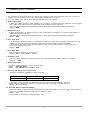
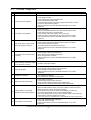
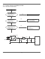
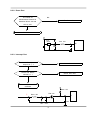
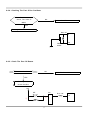
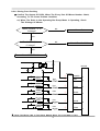
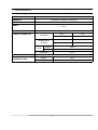
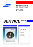
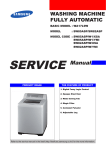
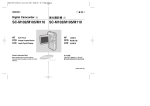
WASHING MACHINE
F843GW/YLP
ٛ ERVICE
Manual
WASHING MACHINE
CONTENTS
Caution for the safety during servicing
1. SPECIFICATIONS
2. SAFETY DEVICES
3. OVERVIEW OF THE WASHING MACHINE
4. OVERVIEW OF THE CONTROL PANEL
5. MAIN FUNCTION
6. TECHNICAL POINT
7. GENERAL ERROR FUNCTION
8. TROUBLE DIAGNOSIS
9. TEST MODE
10. DESIGNATION OF MAIN COMPONENTS
11. PCB SCHEMATIC DIAGRAM
11-1. PCB CIRCUIT DIAGRAM
12. SETTING UP A WASH MACHINE
13. ASSEMBLE AND DISASSEMBLE
14. TOOLS FOR DISASSEMBLY AND ASSEMBLY
15. EXPLODED VIEW AND PARTS LIST
Caution for the safety during servicing
1. Do not allow the customer to repair the product.
☞ The person may be injured or the product life may be shortened.
2. Execute A/S after unplugging the power supply unit.
☞ Be care of the electric shock.
3. Do not plug several plugs in the same outlet.
☞ It may cause the fire due to overheat.
4. Check the damage, pressing or burning of the power plug or outlet.
☞ Replace it promptly if it has problem.(may cause the electric shock or fire)
5. Do not clean the main body with the water.
☞ It may cause the electric shock and fire and shorten the product life)
6. The wiring of the harness shall be free from the moisture and tightened during serving.
☞ It shall not be deviated by certain impact.
7. Remove any dust or filth on the housing section,wiring section,connection section during servicing.
☞ Protect the cause of the fire such as the tracking,and etc.
8. Check any mark of the moisture on the electrical parts, harness section and etc.
☞ Replace the parts or remove the moisture.
9. Check the assembly status of the parts after servicing.
☞ Maintain the status before servicing.
10. Pull out the power cord with holding the plug.
☞ Be care of the electric shock and fire when the cord is damaged.
11. Unplug the power plug from the outlet when the wash machine is not used.
☞ Be care of the electric shock and fire due to the strike of the lightening.
12. Do not use or store the spray or flammable materials(including gasoline,alcohol and etc.)
around the wash machine.
☞ Be care of the explosion or fire due to the electric spark.
13. Do not put the bowl of water or wet laundry on the wash machine.
☞ If the water is penetrated to the wash machine, this may cause the electric shock or fire.
14. Do not install the wash machine in the place where the snow or rain falls.
☞ It may cause the electric shock and fire and shorten the product life.
15. Do not push the control buttons with the awl,pin, or sharp materials.
☞ It may the electric shock and trouble.
16. Check the wash machine is leveled horizontally and installed properly on the floor.
☞ The vibration may shorten the product life.
17. Joint the wire by the connector correctly.
☞ When the wire is jointed by the tape, this may cause the fire due to the tracking.
18. When the wash machine is to be laid for the service, put the pad on the floor and lay the product at
side slowly.
☞ If the wash machine is laid front, the relay may be damaged by the tub.
19. When the wash-heater is replaced, check it is inserted in the bracket-heater and screw the nut.
☞ If the wash--is not inserted in the bracket-heater properly, this may cause the noise and
leakage since it is contacted to the drum.
1
7. General Error Function
1. An occurrence of an Error will make a sound of error melody for 5sec and continuously show one of the Error
Displays from the following errors. (But, Fault Check Led will flash for 0.5sec.)
2. All of the steering parts will be off at that time until that error was released.
3. Water Supply Error
- If there is no higher change in water frequency than 100Hz for 2 minutes during the initial time of water supply
and if water level doesn't reach the preset level in 20 minutes, this error will occur.
This error will be released using Start/Pause button, which performs the initial condition of operation.
- Display : “4E”
4. Water Drain Error
- If water level frequency is still lower than the reset level frequency (24.50kHz) in 10 minutes after starting of
water drain, this error will occur.
This error will be released using Start/Pause button, which performs the initial condition of operation.
- Display : “5E”
5. Over Flow Error
- If an abnormal water level frequency is sensed (for occurrence of Over Flow :20.50kHz), Auto Power Off may
release this error and continuously progress water drain until the frequency reached 24.50kHz.
- If Over Flow is also sensed even after the following check of water level frequency indicating that error, it
functions to progress water drain.
- Display : “OE”
6. Door Open Error
- This error will be released by opening Door.
- Display : "dE" in 2-digit, "door" in 4-digit
7. Unbalance Error
- This error will be released by turning off Power S/W, which performs the initial condition of Power-On.
- DISPLAY : “ UE”
8. Water Heater Error
- This error will be released by turning off Power S/W.
- Display : “ HE"(Over Heat),
- Display : "6E", indicating no operation of HE.
9. Pressure S/W (Single Part Trouble) Error
※ Frequency signals(kHz) generated by water level S/W
Water Level
Low
High
Abnormal Frequency
30.00 KHz
15.00 KHz
- If the above frequency signals are displayed longer than 5sec, it indicates Pressure S/W Error.
- Drain water for 3 minutes for that Error, and turn OFF water drain pump. Pressure S/W Error
display “ IE" will be shown. .
10. Abnormal Water Temperature ERROR
- Water drain begins if abnormal water temperature is sensed at the initial time of water supply. If the frequency
higher than 25.24KHz is sensed, water will be drained by force.
- Display : "CE"
- This error will be released by turning off Power S/W.
11
7. General Error Function
11. Natural Drain/Water Leak Error
- If more than 4 times of water supply and safe water level of Heater are sensed for each course, this error will
occur.
- Display : "LE
- This error will be released by turning off Power S/W.
12. Tacho Error
-
If Motor Tacho is abnormal, this error will occur.
If Tacho signals are inputted less than 2 for 2sec after Motor started, this error will occur.
Display : "3E"
This error will be released by turning off Power S/W.
13. Motor TRIAC Short Error
- If Tacho signals are inputted more than 300 every 1sec in the operational interval less than 90RPM, this error
will occur.
Turn off Power S/W at that time.
- Display : "bE"
- This error will be released by turning off Power S/W.
14. Thermistor Abnormal Error
-
If Thermistor circuit is abnormal, this error will occur.
If Thermistor is lower than 0.2V or higher than 4.5V, this error will occur.
Display :"tE"
This error will be released by turning off Power S/W.
12
8. Trouble Diagnosis
- As the micom wash machine is configured of the complicate structure, there might be the service call.
Below information is prepared for exact trouble diagnosis and suitable repair guide.
Caution for the Repair and Replacement
Please follow below instruction for the trouble diagnosis and parts replacement.
1) As some electronic components are damaged by the charged static electricity from the resin part of wash
machine or the human body, prepare the human body earth or remove the potential difference of the
human body and wash machine by contacting the power supply plug when the work contacting to PCB is
executed.
POWER SUPPLY PLUG
2) Since AC220~240V is applied to the triac T1 and T2 on P.C.B, the electric shock may occur by touching
and be careful that the strong and weak electricity are mixed.
3) As the P.C.B assembly is designed for no trouble, do not replace the P.C.B assembly by the wrong
diagnosis and follow the procedure of the trouble diagnosis when the micom is not operated normally.
13
8-1. Trouble Diagnosis
No
Item
Cause and treatment
The power is not supplied
- Is the PCB connector connected well?
- Is the voltage normal?
- Is the power supply plug connected well?
- Is the noise filter connected well?
- Is the secondary output of the power supply transformation normal?
- Is the fuse disconnected? (option)
• If above points are not found, the PCB assembly is out of order.
Replace it.
The water is not supplied.
- Is the knob open?
- Did you push START/PAUSE button after selecting the course?
- Is the water supply valve connected well?
- Is the winding of the water supply valve continuous?
- Is the connection and operation of the pressure switch normal?
• If above points are not found, the PCB assembly is out of order.
Replace it.
The wash does not start though
the water supply is stopped.
- Is the connection and operation of the pressure switch normal?
- Is the pressure switch hose damaged so that the air is leaked?
- Is the pressure switch hose bent?
- Check the operation of the water level switch.
• If above points are not found, the PCB assembly is out of order.
Replace it.
4
The drum does not rotate during
washing.
- Is the belt connected well?
- Is the winding of the motor continuous?
(Rotor winding, stator winding, generator)
- Is the motor protector normal?
• If above points are not found, the PCB assembly is out of order.
Replace it.
5
The drum rotates by one direction
during washing. (The drum rotates
to one direction for SPIN.)
- The PCB assembly is out of order. Replace it.
(Inversion relay open trouble)
6
Drainage problem.
- Is the drainage hose bent?
- Is the winding of the drainage pump continuous?
- Is the drain filter clogged by the waste?
• If above points are not found, the PCB assembly is out of order.
Replace it.
7
Dehydration problem.
- The unbalance is detected.
- Put in the laundry uniformly and start again.
Abnormal noise during SPIN.
- Is the pulley nut loosen?
- Is the transport safety device removed?
- Is the product installed on the level and stable place?
(Little noise may be generated during the high-speed SPIN.)
1
2
3
8
9
Leak breaker or current/leak
breaker is down during washing.
<When the leak breaker and current breaker is installed separately>
- When the leak breaker is down, check and make the earth of the outlet.
- When the current is down, the current is leaked.
<Is the breaker down when the leak/current breaker is combined?>
- Check the rated capacity of the current and leak breaker.
The current breaker may be down due to the lack of the current when the
wash machine and other apparatus are used.
In this case, execute the cold water wash to check whether the current capacity is lack.
10
The heating is not executed.
- Is the wash heater terminal unplugged?
- Is the wash heater normal?
- If above points are not found, the PCB assembly is out of order.
Replace it.
14
8-2 . Problem Checking And Method Of PCB
8-2-1 The Part Of Power Source
NO Power On
YES
The Voltage Of
NO
Betweenⓐand ⓑIs
Check The Trans
As Big As 12V?
YES
NO
The Voltage Of
Check The Diode(D15-D19)
And Condenser(CE5)
Betweenⓒand ⓓ Is
As Big As 12V?
YES
NO
The Voltage Of
Exchange TR7(7805) And
Betweenⓔand ⓓ Is
Check The
As Big As 5V?
YES
Condenser(CE3)
D15,16,18,19
ⓐ
D17
TRANS
ⓒ
TR7
7805
CE3
ⓔ
60
61
62
ⓑ
2200UF
470UF
30
63
CE5
ⓓ
15
8-2-2. Reset Part
The Value Of
NO
Measurement Result Of
Check The Power Source
Between Micom 26 And
Gnd Is 5V?
YES
Check IC3
IC3
7042
R12 100
26
CE1 1UF
8-2-3. Interrupt Part
Check The Curve
Check D15 - D19
Output Of ⓐ ?
Check The Micom
Check TR6, R60
Number 11 ?
Check The Part Of
Oscillator
R60 4.7K
ⓐ
TR6 815
R64 2.2K
11
C22
R61 C23
16
8-2-4. Checking The Part Of An Oscillator
When The Micom 27,28
NO
Check, The Value Is
Check Resonator
8Mhz?
YES
Exchange Micom And Check R29
R29 1M
RESO
27
28
8MHz
8-2-5. Check The Part Of Buzzer
ⓐ Part Confirm DC12V ?
NO
Check The Part Of Power Source
YES
Exchange BZ,
Check R40,R13
12V
IC6
BZ
R13 10K
12
ⓑ
ⓐ
R40 1K
17
8-2-6. Driving Part Checking
◆ Confirm The Output Of DC5V, When The Every Part Of Micom Number Check,
According To The Some Problem Condition
ex) When The Drain Is Not Operating But Pump Motor Is Operating, Check
The 5Voltage Of Micom
Micom Number, 17 Is
NO
Micom Bad
5Voltage?
YES
The Part Of ⓐ Is
NO
Check The IC 65003
0 Voltage?
YES
Check R48, TRIAC4
MICOM
IC65003
TRIAC5
TRIAC3
TRIAC2
TRIAC7
TRIAC4
ⓐ
POWER
R54
ⓐ
PRE
R47
ⓐ
COLD
ⓐ
RINSE
ⓐ
DOOR
ⓐ
PUMP
R58
R51
R48
※ Check The Micom 18th In The Above Method When The Cold Water Is Bad
18
37
19
18
38
16
17
8-2-7. Confirm The Driving Part Of Motor
YES
Motor Is Not Spinning
Check BD1, TRIAC1
NO
Motor Is Not Turnning
YES
Check RELAY2
Right And Left
NO
Check The Tacho Part
12V
MICOM
BD1
CM05
R69
CM2
R71
IC 65003
COIL2
R46
22
TRIAC1
1W 300
15
RELAY3
D13
19
8-2-8. Checking The Tacho Part
Have The Motor Turn In Hand
Is The Rectangular
Check The Surroundings
NO
Curve In The Micom 8,
Circuit And TR5
10th ?
YES
Exchange The Motor
MICOM
R41 4.7K
R39
TR5
R38 1K
8
815
C15
10
C28
20
9. Test Mode
①
②
③
④
1. Driving Compartment Test Mode
A. Hold down “ 1” and “ 2” keys simultaneously and then press POWER S/W “ 4” on.
B. The driving compartment can be tested when you press “ 3” key right after entering
into the initial stage of the TEST MODE.
• Driving Compartment Test
PRE VALVE ON(0.3sec) → OFF(0.3sec) → COLD VALVE ON(0.3sec) → OFF(0.3sec) →
Pump MOTOR ON(0.3sec) → OFF(0.3sec) → MOTOR Left (0.5sec) → OFF(0.5 sec) →
MOTOR Right (0.5sec) → OFF(0.3sec) → HEATER RELAY ON(0.3sec) → OFF(0.3sec)
21
10. Designation of Main Components
10-1 Normal / Reverse Revolution of Motor and R. P. M. Control
8
Rotor
9
CW
5
Stator coil
-
ROTOR
10
PROTECTOR
(150 C)
Stator coil
MIDDLE-SPEED
5
1 2 3 4 5 6 7 8 9 10
+
STATOR
9
TACHO
Rotor
HIGH-SPEED
8
+
CCW
STATOR
10
5
H
WASHING MOTOR
<Figure1>
(± 7%)
Resistance
value
<Figure2>
STATOR(5.10) STATOR(5.1) ROTOR(8.9) TACHO(3.4)
2.07Ω
0.90Ω
2.35Ω
Rated
value
PROTECTOR(6.7) "H"(mm)
34.3Ω
0
45
Code-No.
Remark
DC31-00002E
220~240V/50Hz
10-2 Door safety Device (F1213J/F1013J/F813J)
When Door is closed, door stay closed. if "set" is operated, power supplied to
the door closed, and electronical power flows between
and
22
make it operate.
,
wires have bymetal keep
10-3 Heater
1) Capacity : AC 230V/1900W
2) Location : Bottom of TUB
3) Function : Raise the water temperature
supplied at the wash process.
4) Resistance value : 23~29
5) Thermal Fuse : 128° C
Thermistor
10-4 Detergent tub and water supply value
A Detergent tub is composed of housing and 3 drawers . supplied water flows into the 3 drawer-detergent tub by
way of classifier at each washing process.
three open drainage way whith detergent and supplied water by way of connector located under the housing flows
into washing tub.
the water supply valve is composed of a hot water valve(1 way) and a cold water valve(2way) and water flow per
min in the valve is below.
Cold water valve(2 way)
Hot water valve(1 way)
(OPTION)
V1
V2
water flow(L/min)
10L
10L
5L
resistance value
4.3㏀
4.2㏀
4.2㏀
power consumption
AC 220v ~ 240V 50/60㎐
usable water pressure
0.5 ~ 8 ㎏/㎤
10-5 Shock absorber and buffer spring
This wash machine is equipped with 2 Shock absorbers with same
capacity and with 4 buffer springs. 2 Shock absorber are placed
under the tub and outside case , 4 buffer springs are placed on the
right and left of the upper side of outside case.
Shock absorber function: during wash, dehydration absorb the shock.
buffer spring: buffering the vibration
device
capacity of Shock absorber
Shock absorber
8±2kg
23
10-6 ASSY-TUB BACK
INNER-BEARING
OUT-BEARING
A
B
C
OIL-SEAL
(unit : mm)
TYPE
I
Assy-Housing
Bearing(D)
Assy-Tub Back
DC97-00125D
DC97-00214K
INNER-BEARING(A) OUT-BEARING(B) OIL-SEAL(C)
ø 20
ø 17
ø 24.3
REMARK
10-7 ASSY- DRUM
A
B
C
(unit : mm)
TYPE
(A)
(B)
(C)
CODE-NO.
REMARK
I
ø 20
ø 17
ø 25
DC97-01463J
Lifter type
10-8 ASSY-PUMP DRAIN
1) Capacity : AC 230V 34W
2) Location : Front bottom(R)
3) Resistance : 160Ω ~ 190Ω
24
11. PCB Schematic Diagram
25
11-1. PCB CIRCUIT DIAGRAM
This Document can not be used without Samsung's authorization.
26
12. Setting up a wash machine.
12-1 Remove the safety device for carriage
1) Remove 5 safety device volts with a enclosed wrench for safety device remove
2) Plug the 5 holes with 5 caps after removing the 5 safety device volts.
* Take care of 5 safety device volts and a wrench , you need these when you move wash machine safely.
Caution
You must remove safety device before use , if not, you have much vibration or much load can br impacted on
the machine.
1. Remove safety device behind of machine
2. Plug the 5 holes
● To protect the machine, remove the
● Plug the 5 holes after safety device
assembled 5 safety device
with the caps enclosed inside of
washing tub
12-2 Install the wash machine on the leveled place.
With the water level adjustment device, adjust the 4 adjustment legs to install the machine leveled on the right,
left, front and rear side. machine's install condition and size is following.
12-2-1 Initial assembled condition (ass'y cover top)
1) Adjustment legs are stick to the bottom of the machine,
when the machine comes out of factory. this condition is
ideal for vibration and noise.
2) When you install the machine initially or move the machine in use,
unscrew the 4 legs to the left and place the machine level and spin
the locking nuts and tighten it strongly.
27
12. Setting up a wash machine.
3) Even though adjustment legs came out all the way,
if machine is not levled , prop up the
machine with the wood or brick to make it even.
(Do not use fragile material or slippery material such as laminated paper)
404
17
844
598
12-2-2 The condition of setting up sink( Disassembled Ass'y- Cover Top)
1) Spin the adjustment leg to the left and remove them from the front and rear side of the machine.
2) Remove the 4 locking nuts from adustment legs, and put only adjustment legs back whert those were.
3) After removing the fixing screws(each on right, left side) from the machine whichi is behind ass'y- cover
top, disassemble the assy-cover top.
4) Install the sink.
404
11
821
598
28
12. Setting up a wash machine.
12-3. Door Opening Dimension(Slim Model)
824 mm
②
Side
①
● (When The Door Vertically Open )
The distance between door① and the rear side② is 824mm
Upper
②
③
①
225 mm
255 mm
● (When the door extremely open ※)
The distance between the door edge(①) and the left side of washing
machine(②) is 255mm
※ Maximum door angle(③) is 170°
29
13. Assemble and Disassemble
1. ASS’ Y-COVER TOP
1) Remove two screws fixing the top-cover on back side.
2) Push the top-cover back about 15mm and pull it up.
3) It’ s possible to exchange and service Assy-Panel
(PCB), the pressure-sensor, the noise-filter,
the water valve and trans(option).
2. FRAME FRONT
1) Remove the top-cover and the ass’ y drawer.
2) Remove two screws fixing the control-panel on
front side and the screw on right side.
3) Remove the cover-front(L) by using the (-)driver.
4) Part the diaphragm and the wire diaphragm
away from the frame-front.
5) Remove the eight screws fixing the frame-front.
6) It’ s possible to exchange and service the heater,
the pump, the shock-absorber and the door lock
s/w.
30
m
15m
SCREW
13. Assemble and Disassemble
2
3. BELT
1) Remove the top-cover.
2) Disassemble and assemble the belt.
3) Check the belt is located at center of the motor-pulley.
<When assemble the belt>
Hook the belt on the motor pulley 1) and place it
around the pulley 2).
PULLEY
BELT
1
MOTOR
4. MOTOR
1) Lay down the washer on left side.
2) Remove the wire housing from the motor.
3) Remove the bolt fixing the motor with the box
drive on back side.
4) Remove the motor.
Motor Assemble Hole
Relay
5. How to Assemble the RELAY Housing.
<CAUTION>
Insert the Relay Housing to the Relays on the
opposite direation each other.
Relay Housing (A)
[Relay Housing Color]
A
B
WHITE
BLUE
Relay Housing (B)
31
14. Tools for Disassembly and Assembly
NO.
TOOL
Box driver
1
Replaceable for the box driver.
Double-ended
10, 13 17,19mm Since the bolt runs idle when the box driver is used, use the box
spanner
driver 17mm.
Vice pliers
3
Tool to protect the idle and abrasion of the bolt for the box driver.
Other(Driver, Nipper, Long nose) General tools for the after service.
JIG for the Tub
5
1 (Disassemble and Assemble)
1
4
12
10
13
8
32
10
mm
4
13
mm
2
17
mm
19
mm
5
19
4
Heater (1)
Motor (1), Balance (5)
2 holes of each left and right of the shock absorber
1 Pulley hole
17
2
10mm
13mm
17mm
19mm
3
15. TOP(FRONT) - Exploded View
J014
C051
C008
G040
G082
C010
J006
Y001
P003
C021
G099
G007
V010
C053
C036
P002
V001
V009
V031
F004
V016
V024
33
15. TOP Parts List
NO.
CODE NO.
DESCRIPTION;SPECIFICATION
C008
DC64-00814E
PANEL-CONTROL;F843GW/YLP,ABS,-,-,-,-,WHT
1
C010
DC61-10316B
CAP-RINSE;SEW-740DR,PP(TB-52),-,-,-,WHT,
1
C021
DC64-00864B
INLAY-PANEL;R(P/F/S)843,PC,T0.5,-,-,WHT,
1
C036
DC63-00450A
COVER-FRONT;S821,PP,T1.8,-,-,-,-,WHT,GUI
1
C051
DC97-07427E
ASSY-PANEL CONTROL;MID-PJT/F843,WHT/RUSS
1
C053
DC61-00889A
HINGE-DOOR;HAUZEN(DOM),ZNDC,-,-,-,-,-,18
1
F004
DC64-00646A
HANDLE-DOOR;SD455-PJT,POM,-,-,-,-,WHT,RO
1
G007
DC97-05469Y
ASSY-PANEL FRONT;MID-PJT/R(F/S),WHT/RUSS
1
G040
DC64-00812A
BUTTON-PUSH(P);P/R/F/SLIM,ABS,-,-,SNOW-W
1
G082
DC64-00813A
BUTTON-PUSH(F);P/R/F/SLIM,ABS,-,-,SNOW-W
1
G099
DC64-00811A
BUTTON-PUSH(S);P/R/F/SLIM,ABS,-,-,SNOW-W
1
J006
DC61-00366A
BODY-DRAWER;SL-600,TB-53,-,-,-,-,-,-
1
J014
DC97-06572B
ASSY-HOUSING DRAWER;F-PJT,2WAY/COLD/VALV
1
J014
DC97-02132C
ASSY-HOUSING DRAWER;S1093~S6093/2-WAY,SL
1
P002
DC97-00702A
ASSY-FRAME FRONT;P6091,ROUND-TYPE
1
P003
DC97-00417A
ASSY-FRAME PLATE(U);SWF-P12,FRAME-PLATE(
1
V001
DC63-00391A
COVER-DOOR;HAUZEN(DOM),ABS,-,-,-,-,-,WHT
1
V009
DC61-00013A
DOOR-GLASS;GLASS,NTR,SWF-P12
1
V010
DC64-00653A
DOOR-LOCK S/W;DA,PA6-G,-,H82,W50,-,BLK,2
1
V016
DC66-00358A
LEVER-DOOR;SEW-HW105,ZNDC,-,-,-,-,CR-COA
1
V024
DC61-00890A
SPRING-HANDLE;HAUZEN(DOM),STS304,CD1.0,-
1
V031
DC61-00888A
HOLDER-GLASS;HAUZEN,ABS,-,-,-,WHT,AUTO+M
1
Y001
MFS-F843-00
ASSY PCB PARTS;F843 40CM 4.5KG 800RPM
1
34
QTY
REMARK
15. TUB - Exploded View
R025
R008
R014
R020
R015
R018
R016
R026
R040
R003
R013
R021
R005
V007
R007
R024
R028
R010
R023
R006
35
15. TUB Parts List
NO.
CODE NO.
DESCRIPTION;SPECIFICATION
R003
DC91-12077A
ASSY-CLAMP DIAPHGRAM;SWF-P12,TUB
1
R005
DC97-01463J
ASSY-DRUM;F-PJT/SD-PJT/LIFTER,STS430/FIX
1
R006
DC47-00006B
HEATER;KAWAI,P-SLIM MODEL,SUS316L,-,-,23
1
R007
DC97-00214K
ASSY-TUB BACK;SWF-P8/P6091,LOW-RPM/NO.3
1
R010
DC61-00856A
BRACKET-HEATER;SB-PJT,STS430,-,-,-,-,-
1
R013
DC64-00374A
DOOR-DIAPHRAGM;F1225J,EPDM,-,-,-,-,GRY,-
1
R014
DC62-10303A
HOSE-AIR;-,EPDM,ID24,-,-,L130,BLK,SWF-P1
1
TUB-FRONT
R014
DC62-10272D
HOSE-AIR;S621,PVC,ID4.5,-,-,L520,NTR,-
1
HOSE-PRESSURE
R015
DC62-10305A
HOSE-DRAWER TUB;-,EPDM,ID35,-,-,L158,BLK
1
R018
DC31-00002E
MOTOR-DRUM;HXGN2I.02,SFW-P8,-,50Hz,-,-,L
1
R020
DC66-00060A
PULLEY;FRPP,-,D297,SWF-PV2,ID12.5
1
R021
DC62-00007A
SEAL-OIL;-,NBR(SD25),BLK,-,-,-,P6091/NBU
1
R023
DC97-02138B
ASSY-TUB FRONT;F1215J,F-MODEL/TUB
1
R024
DC62-20311A
VANE-CHECK;SWF-P12,EPDM,-,-,BLK,-,
1
R025
DC67-00038A
WEIGHT-BALANCER;F-PJT(40CM),CONCREET,-,-
1
R026
DC67-00042B
WEIGHT-BALANCER;F1215,GC-150(CHINA),-,-,
1
R028
DC62-40183A
PACKING-TUB;SWF-P12,EPDM,-,-,-,-,-,BLK,-
1
R040
DC67-00050B
WEIGHT-BALANCER;F-1215,GC-150,-,-,-,-,F-
1
V007
DC91-12078A
ASSY-WIRE DIAPHRAGM;SWF-P12,FRAME-FRONT
1
36
QTY
REMARK
DIAPHRAGM
TUB-BACK
DIAPHRAGM
15. CASE - Exploded View
J001
M015
C007
J008
T024
J011
J012
J010
R030
C080
J012
G002
C023
R017
G003
G018
P007
R012
R012
G025
B006
G020
G009
37
15. CASE Parts List
NO.
CODE NO.
DESCRIPTION;SPECIFICATION
B006
DC97-02079C
ASSY-LEG;SB-PJT,SLIM/25MM/CHINA
4
C007
DC96-00625A
ASSY-M.WIRE HARNESS;SD405,ROLD-DOOR
1
C023
DC32-30006P
SENSOR PRESSURE;DN-S14(P1291),TERMINAL-T
1
C080
DC62-00024F
VALVE-WATER;B1215J,NYLON66/250TRMN,-,-,N
1
G002
DC97-02106A
ASSY-FIXER TUB;S1005J,SLIM-PJT
5
G003
DC97-00139E
ASSY-HOSE DRAIN(O);SB-PJT,PP/L1770/CHINA
1
G009
DC96-00149A
ASSY-PUMP DRAIN;P8091/P6091,220~240V/50H
1
G018
DC64-00434A
SHUTTER;F1215J/F-PJT,PP,-,-,-,WHT,-
1
G020
DC61-10672A
COVER-FRONT(L);SWF-P12,PP(BJ-730),-,-,-,
1
G025
DC62-10289B
HOSE-WATER(C);WIP4013SRW,PVC+NYLON,ID10.
1
J001
DC97-00851T
ASSY-COVER TOP;F-PJT,WOOD/MDF/SLIM 40CM
1
J008
DC29-00006B
FILTER-EMI;CDFC-2712R,SLIM,250V,12A,PI38
1
J010
DC67-00051A
HOSE-DRAWER;S1093~S6093,EPDM,-,-,-,-,BLK
0.4
J011
DC61-60180A
SLEEVE-PLUG;NYLON#6,SEW-720DR,-,-,NTR
4
J012
DC61-00708A
SPRING-HANGER;F-PJT,HSWR,CD2.8,-,-,L170,
2
J012
DC61-00708B
SPRING-HANGER;F-PJT,HSWR,CD2.8,-,-,L181,
2
M015
DC96-00146A
ASSY POWER CORD;UCP2,-,250V/16A,-,-,-,-,
1
P007
DC99-00298A
ASSY-PAINT FRAME;F813J,COLD/F-MODEL
1
R012
DC66-00320A
DAMPER-SHOCK;SB-PJT,ABS,-,-,-,-,WHT,AKS-
2
R017
DC67-00107A
HOSE-PRESSURE;S821,PE-BLOW,ID13.2,OD6.2,
1
R030
DC61-40345A
BRACKET-PRESSURE;GI or GA,SWK-P12,T1.0,-
1
T024
DC96-00626A
ASSY-WIRE HARNESS;SD405,SUB(HIGH)
1
38
QTY
REMARK
PUMP-MOTOR
SPRING
FRAME
TUB-FRONT
Screw/Bolt List
CODE NO.
DESCRIPTION:SPECIFICATION
QTY
DC97-02412A
ASSY-BOLT;SWF-P12,MOTOR, M8*L62
3
6011-001421
BOLT-FLANGE;M7,L61(29.4),ZPC(YEL),SWRCH1
5
6011-001421
BOLT-FLANGE;M7,L61(29.4),ZPC(YEL),SWRCH1
1
6011-001492
BOLT-FLANGE;M8,L25,PASS,STS304,NYLOCK,P1
3
REMARK
MOTOR,WEIGHT
BALANCE(R),WEIGHT-BALANCER(L)
WEIGHT(L)
6011-001452
BOLT-HEX;M10,L20,ZPC(YEL),SWCH10AK,ASSY(
1
PULLEY
DC60-40144A
BOLT-HEX;M10,L41,ZPC2(YEL),SM10C/DAMPER
2
DAMPER+FRAME
DC60-40005A
BOLT-HEX;M4,L60,ZPC2(YEL),SS41C,-,-,-,-
1
6011-001447
BOLT-HEX;M8,L123(25),ZPC(YEL),SWRCH18A,W
1
WEIGHT(U)
6011-001448
BOLT-HEX;M8,L170(25),ZPC(YEL),SWRCH18A,W
1
WEIGHT(U)
DC60-40141A
BOLT-HEX;SM10C/DAMPER,HEX,M8,L66,-,ZPC2(
2
DAMPER+TUB
DC60-40146A
BOLT-SPANER;-,-,OD36,T2.5,L52,FE,FZY,-,P
1
ACCESSORY
DC61-00201A
BRACKET-NUT;SBHG-R,P1291,T3,-,-,-,NO-PAI
1
MOTOR
DC61-40348B
BRACKET-NUT;SBHG-R,P1291,T3,-,-,-,NO-PAI
2
DC61-00201A
BRACKET-NUT;SBHG-R,P1291,T3,-,-,-,NO-PAI
1
DC61-40348B
BRACKET-NUT;SBHG-R,P1291,T3,-,-,-,NO-PAI
2
DC60-50010A
NUT-DIAPHRAGM;EGI,M4,-,-,2.5TX20X8
1
DC60-50010B
NUT-DIAPHRAGM;EGI,M4.2,-,-,2.5TX20X8
1
DD60-50018A
NUT-FLANGE;-,M5XP0.8,FZY,MSWR10,-
2
HINGE+FRAME
DC60-50148B
NUT-HEX;SM20C(NYLON),M12,-,-,ZPC3(YEL),-
1
PULLEY
6001-001773
SCREW-MACHINE;TH,+,M5,L12,
2
HINGE+FRAME
6009-001343
SCREW-SPECIAL;PH,TORX,,M4,L10,PASS
1
P/CORD
6009-001342
SCREW-SPECIAL;TH,+,,M5,L11,ZPC(YEL)
2
FRAME(TOP)
6002-000525
SCREW-TAPPING;FH,+,1,M4,L12,PASS,STS304
1
C-PANEL+FRAME
6002-000630
SCREW-TAPPING;PH,+,2S,M3,L8,ZPC(YEL),SWR
2
BD1,TRIAC1
6002-000630
SCREW-TAPPING;PH,+,2S,M3,L8,ZPC(YEL),SWR
2
B/K+PRE-S/W
6002-000554
SCREW-TAPPING;PH,+,2S,M4,L12,ZPC(YEL),SW
3
PCB+C-PANEL
6002-000554
SCREW-TAPPING;PH,+,2S,M4,L12,ZPC(YEL),SW
1
HOUSING-DRAWER
6002-001327
SCREW-TAPPING;PWH,+,1,M4,L12,NI PLT
2
SHUTTER
6002-001327
SCREW-TAPPING;PWH,+,1,M4,L12,NI PLT
2
C/TOP+FRAME
6002-000470
SCREW-TAPPING;TH,+,1,M4,L10,ZPC,SCRCH18A
2
B/K-C.T
6002-000471
SCREW-TAPPING;TH,+,1,M4,L12,PASS,STS304,
1
VANE-CHECK
6002-000213
SCREW-TAPPING;TH,+,1,M4,L12,ZPC(YEL),SWR
1
CLAMP-HOSE+FRAME
6002-000213
SCREW-TAPPING;TH,+,1,M4,L12,ZPC(YEL),SWR
1
6002-001006
SCREW-TAPPING;TH,+,2S,M4,L12,-,STS410
2
6002-001006
SCREW-TAPPING;TH,+,2S,M4,L12,-,STS410
11
6002-001006
SCREW-TAPPING;TH,+,2S,M4,L12,-,STS410
2
PUMP+FRAME
6002-000444
SCREW-TAPPING;TH,+,2S,M4,L14,NTR,STS304
2
B/K-HEATER
6002-000445
SCREW-TAPPING;TH,+,2S,M4,L18,NTR,STS304
2
6002-000239
SCREW-TAPPING;TH,+,2S,M4,L8,ZPC(YEL),SM2
11
6002-000239
SCREW-TAPPING;TH,+,2S,M4,L8,ZPC(YEL),SM2
2
PANEL+FRM+HOUSING-D
FRAME+FRAME-FRONT,FRAME+PL
ATE-UPPER
MAIN PCB1,MAIN PCB2
6006-001170
SCREW-TAPPING;WS,TH,+,M4,L10,ZPC(YEL)
2
6006-001170
SCREW-TAPPING;WS,TH,+,M4,L10,ZPC(YEL)
2
6006-001170
SCREW-TAPPING;WS,TH,+,M4,L10,ZPC(YEL)
1
6003-000226
SCREW-TAPTITE;TH,+,S,M4,L8,ZPC(YEL),SWRC
2
W/V+FRAME
DC60-60040A
WASHER-NYLON;-,ID10.5,OD32,T2,-,PBSP-1/2
5
FIXER
DC60-60044A
WASHER-PLAIN;-,ID10.5,OD30,T3,-,STS304
2
DAMPER+TUB
DC60-60044B
WASHER-PLAIN;SBC,ID8.4,OD30,T3,-,-,-
5
FIXER
39
DOOR-S/W
E/W(SUB)+FRAME(F),FILTER-EMI
B/K-PRESSURE+FRAME,P/CORD(E/
W)
ELECTRONICS
This Service Manual is a property of Samsung Electronics Co.,Ltd.
Any unauthorized use of Manual can be punished under applicable
International and/or domestic law.
40
©Samsung Electronics Co., Ltd. 2004 MAY
Printed in Korea
Code No. : DC68-02202A
1. Specifications
FRONT LOADING TYPE
TYPE
W 598mm X D 404mm X H 844mm
DIMENSION
50 kPa ~ 800 kPa
WATER PRESSURE
WEIGHT
65 kg
4.5 kg (DRY LAUNDRY)
WASH and SPIN CAPACITY
POWER CONSUMPTION
WASHING
WASHING and
HEATING
SPIN
70 W
240 V
70 W
220 V
1800 W
240 V
2100 W
MODEL
F843
230 V
220W
PUMPING
34 W
43ℓ(STANDARD COURSE)
WATER CONSUMPTION
SPIN REVOLUTION
220 V
MODEL
F843
rpm
800
2
2. Safety Devices
※ We adapt 5 safety devices for users to use this wash machine safely.
1) Balancing device (ASSY-Main PCB)
→ When the lauandry is out of balance, to prevent the noises and vibrations, the unbalance
detecting sensor helps the laundry laid even and continue the dehydating process.
2) Anti-over water supply device
→ Because water supply valve is broken, once water is supplied to the 2/3 level of the door, the
water supplied is drained automatically, Over -flow error (E3) is diplayed on the panel
3) Temperature-regulating device(thermistor)
→ To prevent over-heating over the temperature setted up, THERMISTOR senses the temperature of
the machine continuously and helps the wash machine to work at the temperature given by users.
4) Overheating- controlling system
→ Under the circumstances of THERMISTOR inferiority or abnormal condition, if wash-heater is
overheated, automatically, assy -thermal fuse cuts off the power supply to protect the machine to
keep it safe.
5) Delicate clothing safeguard function(ASSY-Main PCB)
→ To protect the clothings which is weak to high temperature, the wash machine senses the
temperature inside the washing tub. if the temperature rises over 50℃ wool washing course and
Delicate washing course display abnormal water temperature on the panel , after draining the
water.
3
3. Overview of the Washing Machine
OPTION
4
4. Overview of the control panel
5
5. Main function
1) Auto power S/W off function
● After power on, the auto power S/W off function automatically switches power off for you if you do not press
selection button for 10 minutes
● After selecting the function, the auto power S/W off function automatically switches power off for you if you do
not press start/pause button for 10 minutes
● until 5 minutes past, After finishing the last function, the auto power S/W off function automatically switches
power off for you if you do not re-select the course button or manual button
2) Door open function
● If door is open during the operating, all operating is halted, and door error message will be displayed (2-digit
panel displays "Ed" 4-digit panel displays "door") and error melody will coming out
● Door open error can be cleared by closing the door. the operating keeps going on
3) Rinse hold function
● If rinse hold function selected, the operating is finished , the machine do not drain the water after last rinse
4) No spin function
● If no spin function selected, the operating is finished after last rinse
5) Drain function
● Drain function is over, after pumping out the water for 2 minutes , without motor rotating
6) Pre-washing function
● Pre-washing function can be selected ,when you choice the following mode; cotton, coloreds, sythetics, delicates,
baby cotton
● Water level/reverse time is the same with the selected course
● Pre-washing takes about 15 minutes
7) Rinse+ function
● This function practises rinse process once more
6
5. Main function
8) Power-out compensation function
● If power is out on selected process, the process before power out is stored to EEPROM, once power is back
the process before power out continues.
● When power is back, washing process starts from the process at the point of the power out, rinse/drain process
starts from the initial process.
POWER-OUT COMPENSATION FUNCTION PROCESS
START
WASHING
RINSE/DRAIN
RINSE/DRAIN
START
PROCESS
POWER OUT
SAVE DATA
READ DATA
(PROCESS+TIME)
POWER OUT
to EEPROM
SAVE DATA
to EEPROM
FINISH
POWER BACK
POWER BACK
MICOM RESTORE
MICOM RESTORE
RESTART
PROCESS
9) Water heater Error function
① This function starts working, when the heater works abnormally.
(this function begins sensing the heater 2 minutes later, after the heater operating)
② The value of the initial thermistor(A1) is compared with that of the thermistor(A2) in 2 minutes (Y=A2-A1)
- For 10 minute the variance of temperature(Y) is less than 2℃ "E5"message is displayed on the panel.
③ The value of the initial thermistor(A1) is compared with that of the thermistor(A2) in 11 minutes (Y=A2-A1)
- For 1 minute the variance of temperature(Y) increases more than 7℃(0.3V) "E6"message is displayed on the
panel.
④ At this time heater, Error "E5 (heater do not work), E6(overheated)" is displayed and all working process off
⑤ The heater operating continues during heating hours, if washing hour is left over, the residual washing process
keeps going without heating.
7
5. Main function
10) Fuzzy washing function ( weight-sensing)
☞ After finishing initial water supply,
when the fall of the water level needs supplementary water supply,
Sensing function perceives the weight with the supplementary water supply numbers and starts to work.
Under the course of Cotton, or Coloureds, if the supplementary water supply numbers become 3 - 4 times the
function is going at default condition ( high water level ), if 1-2 below that is going at middle level, if 0 below
low water level, heating hours and rinse hours depend on the above data.
ECO PRE mode is selected, the process going on at default condition.
Washing hours
Rinse water level
Cotton
Coloureds
High
Default
Default
Default
Middle
Default-12 min
Default-7min
23.30KHZ
Low
Default-25 min
Default-15min
23.70KHZ
※After sensing weight, above hours is decreased from above default hours
11) Bubble -detecting function
At the each condition of washing&dehydrating , rinse&dehydrating , hydrating, bubble -detecting function works,
this function works 5times normally, if the function detects bubbles at 6 times , the bubble-detecting function
stops and go on to the next process.
● The bubble-detecting function during washing & dehydrating to rinse & dehydrating
after 2 times instant dehydrating and before main dehydrating, if the water level is under 25.45KHZ, Bubble
→ Detecting function thinks there are bubbles and add the bubbles-removing rinse, needing hours are above
hours and 8 min 40 sec.
→ The bubble-detecting function during single hydrating process
after 2 times instant dehydrating and before main dehydrating , if the water level is
25.45KHZ below or
during main dehydrating, water level data is 23.80KHZ below Bubble-detecting function thinks there are
bubbles and add the bubbles-removing rinse 1 times, needing hours are above hours and 5 min 55 sec.
Bubble-detecting function operating process
500rpm
200rpm
20 sec
laundry scattering
draining &reverse
1 min
unbalance
detecting range
bubble detection
8
5. Main function
12) Unbalance detecting & laundry balance positioning system
① Just before the hydrating process and just after reversal rotation for balancing laundry position, this function is
carried out
② The initial 6 sec is the period of reversal rotation for balancing laundry position , Drum rotates 50rpm for
initial 6 sec
③ Next 10 sec, the rotation increases the speed from 50 rpm to 90 rpm slowly
④ During the next 18 sec, drum rotates at the speed of 90 rpm,
the sensor decides the degree of laundry
unbalance with TACHO data which is attached to motor
⑤ If the degree of unbalanced laundry is over 6 times to default value, laundry balancing system carries out
feed back process 6 times
Unbalance detecting & laundry balance positioning system
500rpm
600rpm
500rpm
200rpm
20 sec
laundry scattering
unbalance
detecting range
90rpm
13) R.P.M control
The rotating motor enables the magnetics( i.e generator) to generate magnetic flux in proportion to r.p.m,
magnetic flux induced by coil sensor in the opposite side produces the wave like the figure below to dΦ/dt and
via rectangual wave generating citcuit, the waves reaches MICOM and micom controls r.p.m with the pulse,
count and cycle inputted by program.
<COIL electrical wave at both ends>
V (VOLT)
Vp
T (HOUR)
9
6. Technical point
1) Motor on/off time at each course
Course
unit:sec
Washing
Rinse
Motor r.p.m
Cw
Off
Ccw
Off
Cw
Off
Ccw
Off
Cotton
13
3
13
3
10
5
10
5
50
Coloureds
11
4
11
4
10
5
10
5
50
Synthetics
7
8
7
8
7
8
7
8
40
Delicates
5
10
5
10
5
10
5
10
30
Wools
2
58
2
58
2
28
2
28
25
Quick
12
3
12
3
10
5
10
5
45
※ Motor on/off time is measured in cold water, in heating time motor on/off time is 10 sec on and 5sec off in
the cotton course, beside cotton course, in the other course motor on/off time is the same with that of cold
water use.
2) Final dehydrating r.p.m at each course
Model
unit:rpm
F843
Course
Cotton
1000
Coloureds
1000
Synthetics
800
Delicates
600
Wools
400
Quick
1000
※ You can change the r.p.m to the above a table by use spin button under no spin situation.
3) The water supply control at each process cycle
Model
F843
Process cycle
Washing
Cold water 5L/min / cold 10L/min
Rinse
Cold 10L/min
Final rinse
Cold water 5L/min + cold 10L/min
10