1
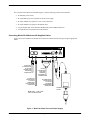
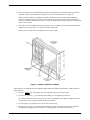
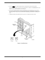
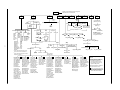
COMSPHERE 3900 Series Modems
Models 3910 and 3911
Installation Instructions
Document Number 3910-A2-GK41-40
February 2002
Overview
The COMSPHERE 391x Series modem family is available in two models: the Model 3910 (a standalone
modem), and the Model 3911 (a carrier-mounted version of the standalone unit). This document provides the
following information:
• A list of equipment supplied with the modem
• A list of customer supplied equipment
• Installation instructions
• Important safety instructions
• Regulatory notices
• Government requirements and equipment return information
This document is intended to be used in conjunction with the COMSPHERE 3900 Series Modems, Models 3910
and 3911 Point-to-Point/Multipoint, Installation and Operation Manual, Document No. 3910-A2-GN32. This
manual is available online at www.paradyne.com. Select Library -> Technical Manuals -> Business Class
Analog Modems.
391x Series Modem Package
After opening the modem’s package, check for damage and verify that the following items are present:
For the standalone model
• Installation instructions
• Model 3910 modem
• Power supply
• One 6-position, 4-wire modular cord (in selected models)
• One 8-position, 8-wire modular cord (in selected models)
For the carrier-mounted model
• Installation instructions
• Model 3911 modem
• Rear connector plate with two DB-25-S edge card connectors
1
If any hardware components are damaged, notify your sales representative. Return equipment using the
procedures described in the Government Requirements and Equipment Return section.
Customer-Supplied Equipment
The following customer-supplied equipment is required to complete a data communications system using the
Model 3910 modem:
• A DTE with an available EIA-232-D serial port.
• A standard EIA-232-D cable with a DB-25-P (plug) connector at one end to attach to the modem.
• One of the following modular leased or dial network interfaces:
— JM8 for leased-line applications.
— RJ11C for dial permissive applications.
The following customer-supplied equipment is required for the installation of a Model 3911 modem:
• A COMSPHERE 3000 Series Carrier.
• A 50-pin mass termination cable.
• One of the following modular or 50-pin leased or dial network interfaces:
— RJ11C for single line dial permissive applications
— RJ21X for multiple line dial permissive applications
— 66 punchdown block
• One Network Interface Module (NIM) for modems installed in Slots 1–8 and one NIM for modems
installed in Slots 9–16 (required for dial-line applications).
For installation of the COMSPHERE 3000 Series Carrier into a cabinet, refer to the COMSPHERE 3000 Series
Carrier, Installation Manual, Document No. 3000-A2-GA31.
Model 3910 Input Voltage Requirements
The power supply used with the Model 3910 modem (Figure 1) is auto-sensing and capable of operating (without
restrapping) with input voltages from 100 Vac to 250 Vac, and input frequencies from 50 Hz to 60 Hz.
Model 3910 Modem Installation
Before installing your standalone modem, make sure your installation site is clean and well-ventilated. Allow
space around the modem for installing cables and telephone cords, and make sure the modem is located within
reach of the ac power outlet. The distance between your modem and DTE should be minimized if DTE data rates
exceed 19,200 bps. Also, low capacitance cables may be necessary for speeds greater than 19,200 bps or distances
greater than 50 feet.
2
The rear panel of the Model 3910 modem (Figure 1) has the following switches and connectors:
• An ON/OFF power switch.
• An 8-pin DIN type power receptacle for the dc power supply.
• An 8-pin modular keyed jack for 4-wire/2-wire leased lines.
• An 8-pin modular keyed jack for dial (PSTN) lines.
• A 4-pin modular jack for the Network Management System (NMS) connection.
• A 25-pin DB-25-S receptacle for the DTE interface.
Connecting Model 3910 Modems with Supplied Cables
Figure 1 shows how Model 3910 modems are connected to certain TELCO jack types using the appropriate
cables.
DTE 2
DTE 3
LEASED DIAL
8-POSITION,
8-CONDUCTOR
PLUG FOR
LEASED-LINE
NETWORK
OPERATION
6-POSITION,
4-CONDUCTOR
PLUG FOR
PERMISSIVE
DIAL NETWORK
OPERATION
DTE 1
DTE 4
NMS
PWR
ON OFF
DB-25-P
CONNECTOR
FOR DATA
TERMINAL
EQUIPMENT
OPERATION
SUB-MINIATURE,
4-CONDUCTOR
PLUG FOR
NETWORK
MANAGEMENT
OPERATION
POWER
SUPPLY
NOTE: DTE 2, 3, AND 4 ARE
FOR FUTURE OPTIONS
Figure 1. Model 3910 Rear Panel and Power Supply
3
DTE Connection
Use the following procedures to connect the EIA-232-D cable from the modem to the DTE:
1. Make sure the modem’s rear panel power switch is OFF.
2. Connect the DB-25-P (plug) connector on the cable to the DB-25-S (socket) connector labeled DTE
(Figure 1) on the modem’s rear panel. Use a small screwdriver to secure the cable to the modem.
3. Connect the DB-25-P connector on the cable to the DB-25-S connector on the DTE. Use a small
screwdriver to secure the cable to the DTE.
Model 3910 4-Wire/2-Wire Leased-Line Connection
Use the following procedures to connect a Model 3910 to the leased-line network interface:
1. Insert the 8-position, 8-conductor modular plug into the jack labeled LEASED (Figure 1).
2. Insert the other end of the modular cord into the leased-line network interface.
3. If the Model 3910 has a dial backup line, follow the steps listed in the Model 3910 Dial-Line Connection
section.
Dial Network Connection
The telephone company provides the line termination jacks for the permissive service you request. Advance
coordination with the telephone company is suggested when connecting the modem to telephone dial lines
(PSTN).
In the Permissive mode, the modem’s transmit output level is fixed at –9 dBm. The telephone company assumes
that the line loss is 3 dB and no compensation is provided for additional losses. A Permissive mode telephone line
is usually terminated with a USOC RJ11C jack.
Model 3910 Dial-Line Connection
For the Model 3910, use the following procedures to connect the modem to the dial network interface:
1. Insert the 6-position, 4-conductor modular plug into the jack labeled DIAL (Figure 1).
2. Insert the other end of the modular cord into the dial network interface.
Network Management System Connection
For the Model 3910, use the following procedures to connect the modem to the network management system
interface:
1. Insert the sub-miniature, 4-conductor modular plug of the 3600 Hubbing Device into the jack labeled
NMS (Figure 1). Refer to Document Number, 3610-A2-GZ45, 3600 Hubbing Device Feature
Number 3600-F3-300, Installation Instructions, for a description of the 3600 Hubbing Device.
Installation for the 3910 is the same as for the 3610 DSU.
2. Connect the 3600 Hubbing Device to the network management channel.
4
Power Supply Connection
Use the following procedures to connect the modem to an ac power outlet:
1. Make sure the modem’s power switch is in the OFF position.
2. Insert the power supply’s 8-pin DIN connector into the modem’s rear panel dc power receptacle
(Figure 1).
3. Connect the power supply to a grounded ac power outlet.
Modem Power-Up
Once your modem is properly connected to the power supply, leased and/or dial lines, and the DTE, press the
modem’s rear panel power switch to the ON position. The modem begins a power-up self-test, in which all DCP
LEDs light. This test takes several seconds to perform, and verifies the operation of most hardware components
within the modem. If successful, the LCD displays Power On Selftst Passed and continues to the Top-Level
menu screen.
Power On Selftst
Passed
F1
F2
F3
3-1
If a failure occurs during the self-test, the LCD displays Power On Selftst Failed for several seconds. The LCD
then displays the Top-Level menu screen with the message Power on Fail appearing on the top line of the LCD.
Although a failure has occurred, the modem will attempt to operate. This allows you to activate a more thorough
self-test using the Test branch. For a better understanding of the Test branch, refer to Chapter 3, DCP Operation,
in Document No. 3910-A2-GN32.
Selecting Factory Configuration Options
After the modem passes the power-up self-test, configure it for operation using one of the six factory preset
configurations.
The purpose of having preset configurations is so that you can have a “head start” in getting your modem
operating and reduce the amount of time required to configure your modem. For a better understanding of DCP
operation and factory preset configuration options, refer to Chapter 4, DCP Configuration, in Document No.
3910-A2-GN32.
Using the Diagnostic Control Panel (DCP)
The DCP’s liquid crystal display (LCD) consists of two 16-character lines which display modem status, control
functions, and configuration options as well as indicating your location in the Top-Level menu tree.
To change a factory template from the Sync Leased preset configuration using the DCP, perform the following
steps:
1. Press the function key below Configure to select the Configure branch.
The LCD now displays Ld EditArea frm.
5
2. Press the
key until Factory comes into view, then press the F1 key to display the factory preset
configurations.
3. Press the
key until the appropriate factory preset appears on the LCD, and press the corresponding
function key to select your choice. (For certain factory presets you will also need to choose the
appropriate mode.)
4. Choose Function appears and displays the Edit and Save functions.
5. Press the F3 key (Save) to save the new factory preset configuration to one of three configuration areas,
Active (Saved), Customer 1, or Customer 2.
(These three configuration areas are nonvolatile memory locations. Active (Saved) contains the most
recently saved changes to any configuration options. In the event of power loss, the modem retrieves these
configuration options. Customer 1 and Customer 2 are user-defined configuration areas.)
The LCD now displays Sav EditArea to.
6. Press the
key until the appropriate configuration area appears on the LCD, then press the
corresponding function key to select your choice. (Saving configuration options to the Active (Saved)
configuration area automatically saves them to the Active (Operating) configuration area.) The LCD
displays Command Complete.
7. The modem is now configured with the selected factory template. Press the
Top-Level menu.
key to return to the
Using AT Commands
When using AT commands, the following criteria must be met:
• Make sure the asynchronous DTE’s communication software is configured for 10-bit character format (for
example, 8 data bits, no parity, and 1 stop bit).
• Make sure the DTE cable is attached to the DTE connector on the rear of the 391x Series modem and to the
correct serial communications port on the asynchronous DTE.
• Configure the modem for Async Dial as described earlier in Using the DCP. To verify that the modem is
connected and functioning properly, enter the following:
TYPE:
AT
PRESS:
Return (Enter)
The screen displays OK.
If the modem does not return OK, refer to Appendix B, Troubleshooting, in Document No. 3910-A2-GN32.
NOTE
If the factory preset configuration is something other than Async
Dial, you do not have AT command control. To regain AT command
control, select, via the DCP, the Async Dial factory preset
configuration as described earlier in Using the DCP.
6
To change a factory template using AT commands, perform the following steps. For more information on
changing factory templates using AT commands, refer to Chapter 5, AT Command Set and S-Registers, in
Document No. 3910-A2-GN32.
1. Use the AT&F&W command to load the appropriate factory configuration to the appropriate storage
area. Enter the following:
TYPE:
AT&Fy&Wn
Where:
y is one of the Factory configurations. For example:
0 for Async Dial
1 for Sync Dial
2 for Sync Leased (Answer)
3 for UNIX Dial
4 for Sync Leased (Originate)
5 for Async Leased (Answer)
6 for Async Leased (Originate)
7 for TMp (Control)
8 for TMp (Trib)
NOTE
&F0 and &F3 allow you to use AT commands after saving a factory
configuration. Other selections remove AT command control. The
only way to return to AT command control is through the DCP as
described earlier in Using the DCP.
Where:
n is one of the following storage areas:
0 for Active (Saved)
1 for Customer 1
2 for Customer 2
NOTE
These three configuration areas are nonvolatile memory locations.
Active (Saved) contains the most recently saved changes to any
configuration options. In the event of power loss, the modem
retrieves these configuration options. Customer 1 and Customer 2
are user-defined configuration areas.
PRESS:
Return (Enter)
2. The selected factory configuration is saved.
To establish a connection with a remote modem, use the D (Dial) command. For more information on AT
commands, refer to Chapter 5, AT Commands and S-Registers, in Document No. 3910-A2-GN32.
7
Removing and Replacing Model 3910 Modems
To remove and replace a Model 3910 modem, perform the following steps:
1. Make sure the modem is offline, and press the modem’s rear panel power switch to the OFF position.
2. Disconnect the power cord from the ac power outlet, and then disconnect the dc power cable from the
connector on the rear of the modem.
3. Disconnect the dial and leased-line modular cords from the modem’s rear panel.
4. Disconnect the DTE interface cable from the modem’s rear panel.
If the modem is to be removed for service, return it using the procedures described in Government
Requirements and Equipment Return.
5. Install the replacement modem as described in the Model 3910 Modem Installation section, and configure
it the same way as the modem being replaced.
Model 3911 Modem Installation
CAUTION
If the Model 3911 is removed from the carrier, always use a
ground strap when handling the modem. Always store the
Model 3911 in an antistatic bag when it is removed from the
carrier.
The Model 3911 is designed for installation in a COMSPHERE 3000 Series Carrier which supplies both the
operating power and the leased and/or dial network connections. For correct power, DTE, dial-line, leased-line,
and network management cabling information, refer to the COMSPHERE 3000 Series Carrier, Installation
Manual.
The COMSPHERE 3000 Series Carrier has 17 slots which can hold up to 16 modems and one shared diagnostic
unit (SDU). The SDU is required when the modems in the carrier are controlled by an NMS, or when multiple
carriers in a cabinet configuration are to be controlled by a single shared diagnostic control panel (SDCP). The
SDCP of the COMSPHERE 3000 Series Carrier is the user interface to the Model 3911 modem. A single SDCP
can control up to eight carriers containing up to 128 compatible modems.
The installation of a Model 3911 varies slightly if an SDCP is installed on the front of the carrier. To install a
Model 3911 modem into the carrier without an SDCP, perform the following steps:
1. At the rear of the carrier, install the rear connector plate. Make sure the plate uses the same slot position as
that intended for the modem.
Loosely fasten the plate. This allows for slight adjustments later when installing the modem.
8
2. At the front of the carrier, hold the modem vertically, with the latch on its faceplate in the open position,
and insert it into the top and bottom card guides of one of the slots numbered 1–16 (Figure 2).
Slide the modem into the slot, aligning the modem with the rear connector plate, until the backplane
connector and DTE connector seat firmly into the back of the carrier. The faceplate latch automatically
closes as you push the modem into the carrier. To lock the modem into the carrier, press the faceplate latch
until a “click” is heard.
3. If the carrier is ON, the Power LED on the faceplate of the 3911 lights. After several seconds the modem
completes its power-up self-test, in which all faceplate LEDs light.
Return to the rear of the carrier and tighten the rear connector plate.
Figure 2. Installing a Model 3911 Modem
If the modem is to communicate with an installed SDCP, install the modem as described above and perform the
following steps:
1. Press the
Select
key on the SDCP. The cursor appears in the carrier selection entry.
2. Press the F1 ( " ) or F2 ( # ) key until the carrier number you want appears on the LCD.
The carrier number selection has a range of 1 to 8 since a single SDCP can control a configuration of up
to eight carriers. (This is only possible if the SDU is installed.)
3. Press the
key to position the cursor on the slot selection entry.
4. Press the F1 ( " ) or F2 ( # ) key until the slot number you want (1–16) appears on the LCD. Ignore the
AB designator that appears on the LCD since it is not applicable to the 391x Series modems.
9
5. Press the
Select
key to place the SDCP in direct communication with the selected modem.
The LCD displays the Top-Level menu for the selected modem. In addition, the Front Panel LED on the
modem’s faceplate and the OK LED on the SDCP light.
6. Once you have determined that the modem is installed properly and completed its power-up self-test,
rotate the circuit pack lock until it covers the faceplate latch (Figure 3) and tighten the retention screw on
the circuit pack lock. This prevents the modem from accidently being removed once it is installed in a
carrier.
7. Configure the modem as described in the Selecting Factory Configuration Options section.
Figure 3. Circuit Pack Lock
10
Removing and Replacing Model 3911 Modems
CAUTION
If the Model 3911 is removed from the carrier, always use a ground
strap when handling the modem. Always store the Model 3911 in an
antistatic bag when it is removed from the carrier.
It is not necessary to power down the carrier to remove and replace a Model 3911 modem. Perform the following
steps:
1. Rotate the circuit pack lock until the release tab is exposed.
2. Press down on the release tab and pull the modem away from the carrier’s backplane.
Menu Tree
The following page provides a graphic representation of the general menu structure of the front panel or SDCP
display. Use the Menu Tree for reference when performing the modem’s various functions.
11
Displays current status of modem along with
data rate and error control mode.
"Status"
Status
Configure
PList
Ld EditArea frm:
Activ
(Operating)
DeviceHS Identity
Backup
Record
Test
SubHS
Display Clear Change Add Acquire
Factory
Active
Delete
Skip
Sync_Leased
TMp
Call_Setup
Tlk/Data
Dial
Answer
Disconnect
Remote
Choose Address
(TMP Control only)
Change_Directory
Dial_Standby
or
Return_to_Dial
Directory_Status
(Does not appear
in North America)
Directory Locations 1 – 24
Sync_Dial
Security
(Dial
Backup
only)
(Tributary
only)
Customer2
Customer1
Active
(Saved)
Control
Choose Password
(TMP only)
Secondary
Prim
(data blckd)
(ExitRem appears
Async_Leased
Async_Dial
UNIX_Dial
instead of Remote when
Display
Choose Mode
using Remote mode)
Clear
Choose Mode
Self
Rem_Digital_Loop
Pattern
Abort
Line = Pri 4W APL
Line = Pri 2W APL
Control
Loc_Analog_Loop
Loc_Digital_Loop
Answer
Line = Bkup 2W APL
Tri
Originate
Line = Dial Backup
b
Line = Dial ONLY
Line = No Sync
Set_Access_Ctrl Reset_Security
LSD
SigQual1
(3910
(3911
1,2
DTR
RcvLevel
only)
only)
DSR
Sig/Noise1,2
(Admin Password?)
Choose Function
Tst
NrEchLv1
TXD
FarEchLv1
Make_Busy
Reset
Download_Code
RXD
FarEchDel1
or
(DownloadSoftware)
EditPassWdTable
Set_Orig_Secur
EchoFreqOff1 RTS
Speaker Data_Stream
RemoveMakeBusy
NonLnearDist2 CTS
Save
Edit
StrapGroup
Retrains2
Set_Answer_Sec
Set_Admin_PsWd
EIA_LEDS
VF_Thresh_Update
Service_Line
1
These parameters will appear for V.32
or
terbo, V.32bis, and V.32 modulations.
Customer1 Customer2
Active
DiscServLine
2 These parameters will appear for Trellis
(Saved)
(Sync-Leased
Multipoint modulation.
Template only)
VF
Major
Minor
Status
Dial
Thresh
Security
Port1
DTE
Options
Ser#
Mod#
FRev
HPt#
FPt#
12
DTE_Interface
Async/Sync Mode
Async DTE Rate
Asyn #Data Bits
Asyn Parity Bit
Asyn #Stop Bits
DTR Action
DSR Control
RTS Action
RTS Antistream
CTS Control
RTS/CTS Delay
LSD Control
TX Clock Source
Bakup_TXClk_Src
XTXC Clamps TXC
CT111_Rate Cntl
DTE_Rate=VF
Extend Main Ch.
Upstream Port
DTE & VF Alarms
DTE_Dialer
DTE Dialer Type
AT Escape Char
Escape GuardTim
BreakForceEscap
CommandCharEcho
CarriageRtn Char
Backspace Char
Linefeed Char
Result Codes
ExtendResltCode
ResultCode Form
AT Cmnd Mode
V25bis Coding
V25bis IdleFill
V25b NewLineChr
Line_Dialer
AutoAnswerRing#
Dialer Type
DialTone Detect
Blind Dial Paus
BusyTone Detect
"," Pause Time
NoAnswer Timout
Fast Disconnect
Line Crnt Disc
Long Space Disc
No Carrier Disc
No Data Disc
Auto Make Busy
MakeBusyVia DTR
Dial_Line
Dial Line Rate
V32bis Automode
V32bis Autorate
V32bis_Override
Dial TX Level
V22b Guard Tone
V32bis Train
Leased_Line
Leased Mode
LeasedLine Rate
V32bis Autorate
V32bis Override
Leased TX Level
Auto Dial Back
AutoDialStandby
SpecialStandby
DialStandby Time
CarrierOn Level
V27bis Train
V29 TrainOnData
V29 Retrain
V29 Link Config
TMp Train Time
TMp TxPremphasis
Lease_Lookback
Dual_Leased_Ln
BackupLineCheck
V42/MNP/Buffer
Err Contrl Mode
V42bis Compress
MNP5 Compress
EC Negotiat Bfr
EC Fallbck Char
Flw Cntl of DTE
Flw Cntl of Mdm
XON/XOFF Psthru
Mdm/Mdm FlowCtl
Break Buffr Ctl
Send Break Cntl
BuffrDiscDelay
Max Frame Size
RdcdAsyncBufSiz
Test
DTE RL (CT140)
DTE LL (CT141)
Test Timeout
Rcv Remote Loop
V54 Address
V54 Device Type
Misc
StrapsWhenDisc
Speaker Control
Speaker Volume
Access frm Remt
RemAccssPasswrd
Dir#1_Callback
NMS_Call_Msgs
NetworkPosition
NetMngmtAddress
Diag Connection
Mixed Trib F/W
Link Delay(sec)
Security
EntryWait_Time
VF_Prompt_Type
#DTE_PW_Tries
DTE_PW_TermChar
DTE_PW_BkSpChar
Get_User_ID
NMS_Reporting
Answ_Secur_Mode
Originate_Secur
Does not appear in TMp Control
mode.
Does not appear in Remote
mode. (Self, Loc_Digital_Loop,
and Pattern appear if the
secondary channel is used.
Rem_Digital_Loop does not
appear in TMp mode.)
Does not appear if configured
for Synchronous mode.
Some choices within this group
may not appear depending
upon how previous configuration
options have been selected.
98-14592-01
Important Safety Instructions
1. Read and follow all warning notices and instructions marked on the product or included in this document.
2. This product is intended to be used with a three-wire grounding type plug — a plug which has a
grounding pin. This is a safety feature. Equipment grounding is vital to ensure safe operation. Do not
defeat the purpose of the grounding type plug by modifying the plug or using an adapter.
Prior to installation, use an outlet tester or a voltmeter to check the ac receptacle for the presence of earth
ground. If the receptacle is not properly grounded, the installation must not continue until a qualified
electrician has corrected the problem.
If a three-wire grounding type power source is not available, consult a qualified electrician to determine
another method of grounding the equipment.
3. Slots and openings in the cabinet are provided for ventilation. To ensure reliable operation of the product
and to protect it from overheating, these slots and openings must not be blocked or covered.
4. Do not allow anything to rest on the power cord and do not locate the product where persons will walk on
the power cord.
5. Do not attempt to service this product yourself, as opening or removing covers may expose you to
dangerous high voltage points or other risks. Refer all servicing to qualified service personnel.
6. General purpose cables are provided with this product. Special cables, which may be required by the
regulatory inspection authority for the installation site, are the responsibility of the customer.
7. When installed in the final configuration, the product must comply with the applicable Safety Standards
and regulatory requirements of the country in which it is installed. If necessary, consult with the
appropriate regulatory agencies and inspection authorities to ensure compliance.
8. A rare phenomenon can create a voltage potential between the earth grounds of two or more buildings. If
products installed in separate buildings are interconnected, the voltage potential may cause a hazardous
condition. Consult a qualified electrical consultant to determine whether or not this phenomenon exists
and, if necessary, implement corrective action prior to interconnecting the products.
9. In addition, if the equipment is to be used with telecommunications circuits, take the following
precautions:
— Never install telephone wiring during a lightning storm.
— Never install telephone jacks in wet locations unless the jack is specifically designed for wet
locations.
— Never touch uninsulated telephone wires or terminals unless the telephone line has been disconnected
at the network interface.
— Use caution when installing or modifying telephone lines.
— Avoid using a telephone (other than a cordless type) during an electrical storm. There may be a remote
risk of electric shock from lightning.
— Do not use the telephone to report a gas leak in the vicinity of the leak.
13
Notices
WARNING
THIS EQUIPMENT HAS BEEN TESTED AND FOUND TO COMPLY WITH THE LIMITS FOR A CLASS A DIGITAL DEVICE,
PURSUANT TO PART 15 OF THE FCC RULES. THESE LIMITS ARE DESIGNED TO PROVIDE REASONABLE
PROTECTION AGAINST HARMFUL INTERFERENCE WHEN THE EQUIPMENT IS OPERATED IN A COMMERCIAL
ENVIRONMENT. THIS EQUIPMENT GENERATES, USES, AND CAN RADIATE RADIO FREQUENCY ENERGY AND, IF NOT
INSTALLED AND USED IN ACCORDANCE WITH THE INSTRUCTION MANUAL, MAY CAUSE HARMFUL INTERFERENCE
TO RADIO COMMUNICATIONS. OPERATION OF THIS EQUIPMENT IN A RESIDENTIAL AREA IS LIKELY TO CAUSE
HARMFUL INTERFERENCE IN WHICH CASE THE USER WILL BE REQUIRED TO CORRECT THE INTERFERENCE AT
HIS OWN EXPENSE.
THE AUTHORITY TO OPERATE THIS EQUIPMENT IS CONDITIONED BY THE REQUIREMENTS THAT NO
MODIFICATIONS WILL BE MADE TO THE EQUIPMENT UNLESS THE CHANGES OR MODIFICATIONS ARE EXPRESSLY
APPROVED BY PARADYNE.
WARNING
TO USERS OF DIGITAL APPARATUS IN CANADA:
THE DIGITAL APPARATUS DOES NOT EXCEED THE CLASS A LIMITS FOR RADIO NOISE EMISSIONS FROM DIGITAL
APPARATUS SET OUT IN THE RADIO INTERFERENCE REGULATIONS OF THE CANADIAN DEPARTMENT OF
COMMUNICATIONS.
LE PRESÉNT APPAREIL NUMÉRIQUE N'ÉMET PAS DE BRUITS RADIOÉLECTRIQUES DÉPASSANT LES LIMITES
APPLICABLES AUX APPAREILS NUMÉRIQUES DE LA CLASSE A PRESCRITES DANS LE RÈGLEMENT SUR LE
BROUILLAGE RADIOÉLECTRIQUE ÉDICTÉ PAR LE MINISTÈRE DES COMMUNICATIONS DU CANADA.
Government Requirements and Equipment Return
For the 3900 Series standalone modems, the Universal Service Order Code (USOC) for Permissive mode is
RJ11C. The Canadian equivalent to RJ11C is CA11A. For 3900 Series carrier-mounted modems, the USOC for
Permissive mode is RJ21X. The Canadian equivalent to RJ21X is CA21A.
FCC Registration number:
Ringer Equivalence number (REN):
See label on modem
See label on modem
Model 3910
Canadian Certification number:
Canadian DOC Load number:
See label on modem
See label on modem
Model 3911
Canadian Certification number:
Canadian DOC Load number:
See label on modem
See label on modem
Certain governments require that instructions pertaining to modem connection to the public switched telephone
network be included in the installation document. Specific instructions are listed in the following sections.
14
United States
NOTICE TO USERS OF THE PUBLIC SWITCHED TELEPHONE NETWORK
1. This equipment complies with Part 68 of the FCC rules. On the equipment is a label that contains, among
other information, the FCC registration number and ringer equivalence number (REN) for this equipment.
The label is located on the bottom of the Model 3910 modem. This label is located on the Model 3911’s
circuit card assembly. If requested, this information must be provided to the telephone company.
2. An FCC compliant telephone cord and modular plug is provided with this equipment. This equipment is
designed to be connected to the telephone network or premises wiring using a compatible modular jack
which is Part 68 compliant. See Installation Instructions for details.
3. The ringer equivalence (REN) is used to determine the quantity of devices which may be connected to the
telephone line. Excessive RENs on the telephone line may result in the devices not ringing in response to
an incoming call. In most, but not all areas, the sum of the RENs should not exceed five (5.0). To be
certain of the number of devices that may be connected to the line, as determined by the total RENs,
contact the telephone company to determine the maximum RENs for the calling area.
4. If the 391x Series modem causes harm to the telephone network, the telephone company will notify you in
advance that temporary discontinuance of service may be required. But if advance notice is not practical,
the telephone company will notify the customer as soon as possible. Also, you will be advised of your
right to file a complaint with the FCC if you believe it is necessary.
5. The telephone company may make changes in its facilities, equipment, operations, or procedures that
could affect the operation of the equipment. If this happens, the telephone company will provide advance
notice in order for you to make the necessary modifications in order to maintain uninterrupted service.
6. If you experience trouble with this equipment, please contact your sales or service representative (as
appropriate) for repair or warranty information. If the product needs to be returned to the company service
center for repair, contact them directly for return instructions using one of the following methods:
• Via the Internet: Visit the Paradyne World Wide Web site at http://www.paradyne.com
• Via Telephone: Call our automated call system to receive current information via fax or to speak with
a company representative.
— Within the U.S.A., call 1-800-870-2221
— Outside the U.S.A., call 1-727-530-2340
If the trouble is causing harm to the telephone network, the telephone company may request that you
remove the equipment from the network until the problem is resolved.
7. The user is not authorized to repair or modify the equipment.
8. This equipment cannot be used on public coin service provided by the telephone company. Connection to
Party Line Service is subject to state tariffs. (Contact the state public utility commission, public service
commission or corporation commission for information.)
15
Canada
NOTICE TO THE USERS OF THE CANADIAN PUBLIC SWITCHED TELEPHONE NETWORK
The Canadian Department of Communications label identifies certified equipment. This certification means that
the equipment meets certain telecommunications network protective, operational and safety requirements. The
Department does not guarantee the equipment will operate to the user’s satisfaction.
Before installing this equipment, users should ensure that it is permissible to be connected to the facilities of the
local telecommunications company. The equipment must also be installed using an acceptable method of
connection. In some cases, the company’s inside wiring associated with a single line individual service may be
extended by means of a certified connector assembly (telephone extension cord). The customer should be aware
that compliance with the above conditions may not prevent degradation of service in some situations.
Repairs to certified equipment should be made by an authorized Canadian maintenance facility designated by the
supplier. Any repairs or alterations made by the user to this equipment, or equipment malfunctions, may give the
telecommunications company cause to request the user to disconnect the equipment.
Users should ensure for their own protection that the electrical ground connections of the power utility, telephone
line and internal metallic water pipe system, if present, are connected together. This precaution may be
particularly important in rural areas.
CAUTION
Users should not attempt to make such connections
themselves, but should contact the appropriate electric
inspection authority, or electrician, as appropriate.
The Load Number for this equipment is listed on page A of this manual. The Load Number (LN) assigned to each
terminal device denotes the percentage of the total load to be connected to a telephone loop which is used by the
device to prevent overloading. The termination on a loop may consist of any combination of devices subject only
to the requirement that the total of the Load Numbers of all devices does not exceed 100.
If your equipment is in need of repair, refer to the procedures described in the Government Requirements and
Equipment Return section.
Warranty, Sales, and Service Information
Contact your local sales representative, service representative, or distributor directly for any help needed. For
additional information concerning warranty, sales, service, repair, installation, documentation, training, distributor
locations, or Paradyne worldwide office locations, use one of the following methods:
• Internet: Visit the Paradyne World Wide Web site at www.paradyne.com
• Telephone: Call our automated system to receive current information via fax or to speak with a company
representative.
— Within the U.S.A., call 1-800-870-2221
— Outside the U.S.A., call 1-727-530-2340
*3910-A2-GK41-40*
*3910–A2–GK41–40*
16