1
SJ-D59M/P60M
SJ-D64M/P65M
SJ-D69M/P70M
SERVICE MANUAL
S5311SE68CPUT
REFRIGERATOR-FREEZER
Plasmacluster
MODELS
SJ-D59M-GL/GY/SLG
SJ-P60M-GL/GY/SLG
SJ-D64M-GL/GY/SLG
SJ-P65M-GL/GY/SLG
SJ-D69M-GL/GY/SLG
SJ-P70M-GL/GY/SLG
SJ-P60M
SJ-P65M
SJ-P70M
SJ-D59M
SJ-D64M
SJ-D69M
In the interests of user-safety (Required by safety regulations in some
countries) the set should be restored to its original condition and only
parts identical to those specified should be used.
DESTINATION ......................... T
Refrigerant; HFC-134a
Refer to "HFC-134a COOLING UNIT" Service Manual for handling this refrigerant.
TABLE OF CONTENTS
page
CAUTIONS AND INFORMATIONS .................................................................................................................. 2
SPECIFICATIONS ............................................................................................................................................ 3
DESIGNATION OF VARIOUS PARTS ............................................................................................................. 4
LIST OF ELECTRICAL PARTS ........................................................................................................................ 5
DIMENSIONS ................................................................................................................................................... 5
WIRING DIAGRAM ........................................................................................................................................... 7
FUNCTIONS ................................................................................................................................................... 11
ASSEMBLING PROCEDURES OF MAIN PARTS AND CAUTIONS ............................................................. 15
COOLING UNIT .............................................................................................................................................. 23
REPLACEMENT PARTS LIST ....................................................................................................................... 25
SHARP CORPORATION
1
SJ-D59M/P60M
SJ-D64M/P65M
SJ-D69M/P70M
CAUTIONS AND INFORMATIONS
In case of following troubles, the cause is not related with the failure of refrigerator.
Please mention the correct way to the customer for the use of refrigerator when the repairing.
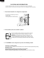
1. Some foods freezed in the refrigerator compartment.
Do not place food directly in front of
cold air outlet.
This may lead to the food freezing.
cold air flow
IN
OUT
2. Some plastic parts were cracked or splitted.
Some household cleaning chemicals may affect the internal
food liner and plastic parts resulting in splitting or cracks
occurring.
When cleaning all plastic parts inside this refrigerator, only
use diluted dishwashing liquid(soapy water). Make sure that
all plastic parts are thoroughly rinsed with water after cleaning.
3. IT IS NORMAL for the refrigerator to produce the following sounds.
Cracking or crunching sound;
Sound produced by expansion and contraction of inner walls and internal parts during cooling.
Squeaking sound;
Sound produced by expansion and contraction of internal parts.
Sound of flowing fluid (gurgling sound, fizzing sound);
Sound of refrigerant flowing in pipes (sound may become louder from time to time).
2
SJ-D59M/P60M
SJ-D64M/P65M
SJ-D69M/P70M
SPECIFICATIONS
Items
Type
Outer dimensions
Height
Width
Depth
Rated storage volume [ ISO ]
(Rated volume)
Gross volume [ ISO ]
Thai standard volume [ TIS ]
Defrosting
System
Start
Finish
Temperature control
No-frost freezer
Interior lamp
Caster
Evaporating pan
Refrigerator
R glass shelf ass'y
Compartment
V glass shelf ass'y
Vegetable case
V parting plate
R door pocket
Egg tray
Bottle pocket
Utility case pocket
Fresh case
Tube stand
Freezer
Freezer shelf ass'y
Compartment
Ice cube maker
Ice storage box
F door pocket
Deodorizing unit
Plasmacluster
RATING
Items
Rated voltage
(V~)
Rated frequency
(Hz)
Climate class
Rated current
(A)
Rated input of heating systems (W)
Refrigerant (Charging quantity) [Non-flammable]
Insulation blowing gas [Flammable]
Net Weight
(kg)
PLUG TYPE
Plug cord
2 pin
Destination mark
COLOR
Items
Outside color
Inside color
SJ-D59M SJ-P60M SJ-D64M SJ-P65M
2-Door
2-Door
1620mm(63.8")
1720mm(67.7")
760mm(29.9")
760mm(29.9")
740mm(29.1")
740mm(29.1")
492 liter (17.7 cu.ft) 535 liter (18.9 cu.ft)
F: 151 liter (5.3 cu.ft) F: 151 liter (5.3 cu.ft)
R: 341 liter(12.1 cu.ft) R: 384 liter(13.6 cu.ft)
526 liter (18.6 cu.ft) 566 liter (20.0 cu.ft)
F: 177 liter (6.3 cu.ft) F: 177 liter (6.3 cu.ft)
R: 349 liter(12.3 cu.ft) R: 389 liter(13.7 cu.ft)
488 liter (17.24 cu.ft) 528 liter (18.66 cu.ft)
F: 157.5 liter(5.57 cu.ft) F: 157.5 liter(5.57 cu.ft)
R: 330.5 liter(11.67 cu.ft) R: 370.5 liter(13.09 cu.ft)
Heater system
Automatic
Automatic
Automatic (Adjustable)
Yes
2
4
1
2
1
1
1
1
2
2
1
1
2
1
Twin ice cube maker
1
2
2 (Honeycomb type)
No
Yes
No
Yes
SJ-D69M SJ-P70M
2-Door
1820mm(71.6")
760mm(29.9")
740mm(29.1")
577 liter (20.4 cu.ft)
F: 151 liter (5.3 cu.ft)
R: 426 liter(15.1 cu.ft)
606 liter (21.4 cu.ft)
F: 177 liter (6.3 cu.ft)
R: 429 liter(15.1 cu.ft)
563 liter (19.89 cu.ft)
F: 157.5 liter(5.57 cu.ft)
R: 405.5 liter(14.32 cu.ft)
No
Yes
SJ-D59M SJ-P60M
220-240
50
T
1.4-1.5
144-170
HFC-134a(120g)
Cyclo pentane (HC)
83
SJ-D69M
SJ-P70M
SJ-D64M
SJ-P65M
HFC-134a(130g)
85
90
Plug type
-GY
Gray
3
2
HFC-134a(125g)
T
-GL
Gold
White
3
-SLG
Silver
SJ-D59M/P60M
SJ-D64M/P65M
SJ-D69M/P70M
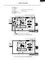
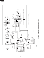
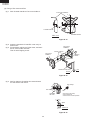
DESIGNATION OF VARIOUS PARTS
The names in parenthesis" [ ]" are the denominations
used in the REPLACEMENT PARTS LIST.
29
1
1. Freezer light [Lamp]
2. Freezer fan
3. Freezer shelf [F shelf ass'y]
4. Ice cube maker
5. Ice cube box [Ice storage box]
6. Deodorizing unit
7. Freezer temp. control knob
8. Fresh case [Chilled case]
9. Refrigerator fan
10. Refrigerator temp. control knob
11. Refrigerator shelf [R glass shelf ass'y]
(59/60/64/65 type; 2 shelves, 69/70 type; 3 shelves)
12. Refrigerator light [Lamp]
13. Shelf [V glass shelf ass'y]
14. Vegetable crisper [Vegetable case]
15. Separator plate [V parting plate]
16. Evaporating pan & cover
17. Casters
18. Adjustable feet [Adjustable leg ass'y]
19. Fan & light switch for freezer
20. Fan & light switch for refrigerator
21. Freezer pocket [F door pocket]
22. Water supply cup [Water cup]
23. Magnetic door seal [Door packing]
24. Utility case [Utility case pocket]
25. Egg holder [Egg tray]
26. Free pocket [R door pocket]
19
2
20
3
4
5
21
22
6
7
23
6
8
9
10
11
24
25
26
27
12
13
14
15
16
23
28
(59/60/64/65 type; 1 pocket, 69/70 type; 2 pockets)
27. Bottle pocket
28. Bottle guard [Tube stand]
29. Plasmacluster panel
17
18
(Only for SJ-P60M,P65M,P70M)
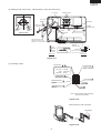
Figure D-1. External Description
Upper hinge cover
Mark: Cold air flow
Freezer fan
Hot pipe
Fan motor
Panel P. W. B
(only for SJ-P60M,P65M,P70M)
Freezer
compartment
Defrost thermostat
Evaporator
Freezer temp. control knob
Defrost heater
Hot pipe
Ionizer (only for SJ-P60M,P65M,P70M)
Refrigerator
compartment
Timer,R-fan thermo ass'y
Refrigerator fan
Damper thermostat
Refrigerator temp. control knob
Drain pipe
Vegetable case
Main P. W. B (only for SJ-P60M,P65M,P70M)
Ventilating grille
Compressor
Starting relay, Overload relay(Protector)
Evaporating pan
Sub condenser
Adjustable leg ass'y
Caster
This figure shows SJ-P65M
Figure D-2. Constructions
4
SJ-D59M/P60M
SJ-D64M/P65M
SJ-D69M/P70M
LIST OF ELECTRICAL PARTS
ITEMS
Thermostat
TYPE NAME
MM1-8123
Defrost thermostat
Thermo. fuse
F-fan motor
R-fan motor
(R-fan fuse)
Defrost heater
Door switch
Damper thermostat
Defrost timer
S101
SF70E
3R00044B
3R00122A
123
MM6-4198
DSD-5
MM1-6176
ND1004M2
Lamp socket (F/R)
F-lamp
R-lamp
R-fan thermo. R-fan thermo.
ass'y
R-fan thermo.heater
Compressor
—
—
—
S101
RSS2
FL2088
RATING
125V 6A
250V 3A
250V 8A
250V 10A
220-240V 50/60Hz
220-240V 50/60Hz
250V 2A
220-240V 353Ω
250V 0.25A
—
220-240V
50/60Hz
SPECIFICATIONS
(At normal notch)
ON/OFF : -19/-24˚C
Open/Close : 10/1˚C
Working temp. : 70˚C
Working with ø100 fan
Working with ø80 fan
Cut OFF 130˚C
150W at 230V
4 terminals push-button type
Open/ Close : 2/-3˚C
Integration type
Cycle time : 10.8/9.0 hours(50/60Hz)
Delay time : 4.3/3.6 min.(50/60Hz)
E-12(Hard plastic body type)
E-12
E-12
Open/ Close : 7/15˚C
1.1W at 230V
Cooling capacity : 245W (50Hz)
Main coil : 9.11Ω
Common
Aux. coil : 16.6Ω
(at 25˚C)
250V 1A
240V 10W
240V 15W
250V 8A
350V, 2W, 10kΩ
220-240V/50Hz
Aux. coil
Starting relay
PGT0SAT
Overload relay(Protector) 2.0C36A3
Ionizer-K(Plasmacluster unit) FTRN-A014CBKZ
—
—
DC 12V
33Ω (at 25˚C)
Open/ Close : 130/60˚C
3.5kV p-p
DIMENSIONS
OUTER DIMENSIONS AND CLEARANCE
more than
60
more than
760
1
more than
60
more than
760
60
A
1420
1480
9.5
553
90
740
520
72.5
60.5
12
B
135
1340
( Unit : mm)
A
B
SJ-D59M,P60M
SJ-D64M,P65M
SJ-D69M,P70M
1620
979
1720
1079
1820
1179
1 Include the panel/badge. Not include the handle.
Fig. E-1
5
Main coil
SJ-D59M/P60M
SJ-D64M/P65M
SJ-D69M/P70M
587
90
174
INNER DIMENSIONS
294
450
264
603
90
587
630
177
125
110
615
355
285
110
b
615
310
607
a
c
615
133
310
d
615
615
607
133
600
242
335
227
SJ-D59M,P60M
a
b
c
d
SJ-D64M,P65M
466
566
180
135
121
180
185
171
( Unit : mm)
The dimensions between shelves can be changed
by setting the shelves on the other rails.
90
603
450
587
90
615
110
615
110
615
110
294
264
587
174
Fig. E-2 (SJ-D59M,P60M,D64M,P65M)
607
133
171
615
615
607
133
600
285
310
310
666
135
615
135
615
180
355
310
335
242
177
125
630
227
( Unit : mm)
The dimensions between shelves can be changed
by setting the shelves on the other rails.
Fig. E-3 (SJ-D69M,P70M)
6
SJ-D59M/P60M
SJ-D64M/P65M
SJ-D69M/P70M
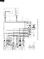
WIRING DIAGRAM
Be sure to replace the electrical parts with specified ones for maintaining the safety and performance of the set.
G
BR
OR
Y
R
P
B
BK
SB
G-Y
W
: GRAY
: BROWN (Live)
: ORANGE
: YELLOW
: RED
: PINK
: BLUE (Neutral)
: BLACK
: SKY-BLUE
: GREEN-YELLOW (Earth)
: WHITE
CONNECTED IN TERMINAL BOX
CONNECTOR
DEF. TIMER
(Br)
R-
2PIN
PLUG/
CORD
MAIN
PWB
F-
L
FM
LAMP
(G)
TM
THERMOSTAT
R-FM
LAMP HEATER R
F
FM
L
THERMO.
FUSE
PC
R-FAN
THERMO
DEFROST HEATER
PROTECTOR
DOOR
PWB
DEFROST THERMO
DOOR SWITCH
STARTING RELAY
(B)
C
M
A
COMPRESSOR
PC : PLASMACLUSTER UNIT (IONIZER-K)
Figure W-1. Wiring Diagram (SJ-P60M,P65M,P70M)
DEF. TIMER
(Br)
R-
THERMOSTAT
R-FM
LAMP HEATER R
2PIN
PLUG/
CORD
F-
L
FM
LAMP
(G)
TM
F
FM
L
THERMO.
FUSE
R-FAN
THERMO
DEFROST HEATER
PROTECTOR
DOOR SWITCH
DEFROST THERMO
STARTING RELAY
(B)
C
M
A
COMPRESSOR
Figure W-2. Wiring Diagram (SJ-D59M,D64M,D69M)
7
L
8
G
BR
OR
Y
R
P
B
BK
SB
G-Y
W
L
FM
3
2
4
1
LAMP SOCKET
: GRAY
: BROWN (Live)
: ORANGE
: YELLOW
: RED
: PINK
: BLUE (Neutral)
: BLACK
: SKY-BLUE
: GREEN-YELLOW (Earth)
: WHITE
R-LAMP (15W)
R-FAN MOTOR
R LAMP BOX ASS'Y
R FAN THERMO.
(R-FAN
THERMO. HEATER)
DEFROST TIMER
TM
3
2
4
1
3
1
4
2
LEAD EV-COVER ASS'Y
LAMP SOCKET
3 (PUSH CLOSE)
1 (NEUTRAL)
4 (PUSH OPEN)
2 (PUSH OPEN)
R CONTROL COV. ASS'Y
DOOR SWITCH
DEF. HEATER ASS'Y
FUSE ASS'Y
DEF. THERMO. ASS'Y
F-THERMOSTAT
FAN MOTOR FM
E. V. COVER ASS'Y
LAMP(10W)
F LAMP BOX ASS'Y
1
2
3
4
1
2
3
4
SB-2
BR-3
OR-3
OR-2
(R-1)
(BK-1)
GY-2
(Y-1)
(Y-2)
OR-2
BL-2
SB-1
(W-2)
BROWN 2
BROWN 1
SOURCE CORD
ORANGE
BLUE 2
BLUE 1
STARTING RELAY
TERMINAL BLOCK
C
M
A
1
2
3
4
MAIN
PWB
COMPRESSOR
OR-4
BR-6
BL-3
GY-3
PWB HARNESS
SKY-BLUE
PROTECTOR
GRAY 2
GRAY 1
CABINET ASS'Y
1
2
1
2
3
1
2
1
2
3
1
2
1
2
3
1
2
TERMINAL BOX
CLUSTER HARNESS PU
CLUSTER HARNESS
CAB HARNESS
Figure W-3. Electric Accessories Layout (SJ-P60M,P65M,P70M)
1 GY-3
(OR-4)
2
SB-3
3
BR-5
4
1
2
3
4
1
Y-2
2
1
2
(W-1)
1
2
3
4
5
6
7
8
9
GY-1
OR-1
R-1
BR-2
Y-1
BL-1
BK-1
W-1
BR-1
1
W-2
2
1
2
3
4
5
6
7
8
9
1
2
1
2
PANEL
PWB
1 2 3
F-DOOR
PLASMACLUSTER UNIT
(IONIZER-K)
DOOR HARNESS
SJ-D59M/P60M
SJ-D64M/P65M
SJ-D69M/P70M
L
FM
TM
9
G
BR
OR
Y
R
P
B
BK
SB
G-Y
W
L
FM
3
2
4
1
LAMP SOCKET
: GRAY
: BROWN (Live)
: ORANGE
: YELLOW
: RED
: PINK
: BLUE (Neutral)
: BLACK
: SKY-BLUE
: GREEN-YELLOW (Earth)
: WHITE
R-LAMP (15W)
R-FAN MOTOR
R LAMP BOX ASS'Y
R FAN THERMO.
(R-FAN
THERMO. HEATER)
DEFROST TIMER
3
2
4
1
3
1
4
2
LEAD EV-COVER ASS'Y
LAMP SOCKET
3 (PUSH CLOSE)
1 (NEUTRAL)
4 (PUSH OPEN)
2 (PUSH OPEN)
R CONTROL COV. ASS'Y
DOOR SWITCH
DEF. HEATER ASS'Y
FUSE ASS'Y
DEF. THERMO. ASS'Y
F-THERMOSTAT
FAN MOTOR
E. V. COVER ASS'Y
LAMP(10W)
F LAMP BOX ASS'Y
1
2
3
4
1
2
3
4
GY-3
(OR-4)
SB-3
BR-5
SB-2
BR-3
OR-3
OR-4
(R-1)
(BK-1)
GY-2
(Y-1)
(Y-2)
OR-2
BL-2
SB-1
(W-2)
BROWN 2
BROWN 1
SOURCE CORD
ORANGE
BLUE 2
BLUE 1
PROTECTOR
SKY-BLUE
C
M
A
TERMINAL BLOCK
STARTING RELAY
GRAY 1
CABINET ASS'Y
COMPRESSOR
TERMINAL BOX
Figure W-4. Electric Accessories Layout (SJ-D59M,D64M,D69M)
1
2
3
4
1
2
3
4
1
Y-2
2
1
2
(W-1)
1
2
3
4
5
6
7
8
9
GY-1
OR-1
R-1
BR-2
Y-1
BL-1
BK-1
W-1
BR-1
1
W-2
2
1
2
3
4
5
6
7
8
9
1
2
SJ-D59M/P60M
SJ-D64M/P65M
SJ-D69M/P70M
LED1
ZD1
10
PC
R21
(1/2W)
680
SW
CN4
2
3
1
CN2
CN3
(MAIN PWB)
PC :
PLASMACLUSTER UNIT
(IONIZER-K)
(PANEL PWB)
F-FM
CN1
2
1
2
3
1
1
7
3
5
R17
(1/2W)
1.8
R11
1K
R1
R2
VRS1
C15
100μ
10V
R18
10K
C13
0.1μ
Q3
KTA1046
TRNS
C10
1μ
50V
R14
1K
Q1
KRA101M
C3
0.1μ
50V
C7
0.1μ
R7
1K
(A/D)
13
C2
2200μ
35V
10
RS2
RS3
4.7K R20
RS1
R8
10K
R19
OPEN
I
IC1
C16
0.1μ
O
I
IC2
O
G
C18
0.1μ
7805
C19
1000μ
25V
11
CST4.00MGW
C5
1μ
50V
C20
100μ
10V
PST993E
IC3
3
1
2
C6
0.1μ
C4
0.1μ
RS1,2,3=43K(1/2W), RS3=OPEN,
VRS1,2=560V
RS1,2,3=18K(1/2W), RS3=10K(1/8W), VRS1,2=270V
RS1,2,3=18K(1/2W), RS3=SHORT,
VRS1,2=270V
CF1
1M R6
C8
0.1μ
C17
100μ
10V
12 5V
[ NOTE ]
1. Resistance which is not specified : 5% 1/8W
2. Rated voltage of the condenser which is not specified : 25V
220 240V
120V
110 120V
TMP47C241N
IC4
VDD
VAREF
R40(AINO) K03
K02
R41(AIN1)
K01
R42(AIN2)
K00
R43(AIN3)
R71(WT0) HOLD
R80(INT2) RESET
XOU
R81(T2)
XIN
R82(INT1)
TEST
P10
R92
P11
R91
P12
R90
P13
P20
VSS
INPUT VOLTAGE
C12
0.1μ
G
7812
12V
Figure W-5. Circuit Diagram (Only for SJ-P60M,P65M,P70M)
C9
0.1μ
D7
ISS270A
R5
2.2K
R4
10K
D3
Q6
KRA101M
D4
D6
IN4005E
D5
PC1
PC123
Q2
KRC101M
R15
4.7K
R13
4.7K
12V
R9
1K
Q7
KRA101M
D2
ISS270A
R3
Q4
KRC101M
R10
2.2K
Q5
KRA101M
C11
0.1μ
2A
VRS2
12V
R16
10K
9
8
7
6
5
C1
0.1μ
250V
2A
D1
IN4007E
R12
2.2K
4
3
2
1
HS
SJ-D59M/P60M
SJ-D64M/P65M
SJ-D69M/P70M
SJ-D59M/P60M
SJ-D64M/P65M
SJ-D69M/P70M
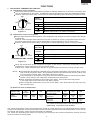
FUNCTIONS
1. ADJUSTABLE TEMPERATURE CONTROL
(1) Temperature control of freezer
Thermostat (senses freezer temperature) operates on ON/OFF switchover to control the compressor and
cool air circulating fan (F-fan motor) , and allows the freezer temperature to keep at a suitable temperature.
However adjust the freezer temp. control knob as follows depending upon the storing condition of foods.
3
MED
4 5
2
7
MAX
Coldest
1
MIN
PURPOSE
KNOB
SETTING
6
MAX(Coldest)
For making ice rapidly or fast freezing.
When restocking with fresh food.
MED
For normal freezing.
For storing frozen food for a short period (up to one month).
FREEZER TEMP. CONTROL
Figure F-1.
When frozen food or ice cream is not stored.
MIN
(2) Temperature control of refrigerator
Damper-thermostat senses temperature of the refrigerator and changes the opening angle of the damper
automatically.
However, as the Damper-thermostat has no function to switch on or off the compressor and F-fan motor,
the freezer temperature control causes temperature in the refrigerator to vary to some extent.
However, adjust the refrigerator temp. control knob as follows depending upon the cooling condition.
MED
4
5
3
MAX
(Coldest)
6
2
For keeping freshness of food longer.
When the refrigerator does not provide sufficient cooling.
Max
7 Coldest
MIN 1
PURPOSE
KNOB
SETTING
For normal operation.
MED
REFRIGERATOR TEMP. CONTROL
When the refrigerator provides excessive cooling.
MIN
Figure F-2.
When the temperature of the refrigerator is higher, R-fan thermo. senses the temperature and the
refrigerator is cooled efficiently by running of R-fan motor.
R-fan thermo. heater energizes when the door is opened intend to promote to running of R-fan motor.
NOTE:
The refrigerator temperature is affected also by the freezer temperature. If the freezer temp. control
knob is set at the position "MAX", the temperature tends to be lower than the following values, and
if set at near the position "MIN", temperature tends to be higher.
If the refrigerator is operated for a long time with the freezer temperature control sets the "MAX"
position, foods stored in the refrigerator compartment may also freeze.
When refrigerator temperature control sets to the "MAX", some foods stored may freeze.
In this case adjust control set back to the "MED" position.
When refrigerator temperature control sets to the "MAX", some foods stored in Fresh case may
also become frozen.
(3) Reference value of temperature
SETTING OF
FREEZER TEMP.
CONTROL KNOB
MAX
(Coldest)
MED
MIN
Freezer
temperature
Approx.
-21 C
Approx.
-18 C
Approx.
-15 C
SETTING OF
REFRIGERATOR TEMP.
CONTROL KNOB
MAX
(Coldest)
MED
MIN
Refrigerator
temperature
Approx.
0C
Approx.
3C
Approx.
6C
Fresh case
temperature
Approx.
-3 C
Approx.
1C
Approx.
4C
The values shown above refer to the case where the
freezer temp. control knob is set at "MED".
The values shown above refer to the measurement carried out center area and 1/3 of overall height from the bottom
at each of the refrigerator and the freezer after machine has been operated at an ambient temperature of 30˚C with no
food stored and the door closed until the temperature is stabilized.
The values vary depending upon frequency of opening and closing the door, ambient temperature, amount of stored
foods and manner of storing foods.
11
SJ-D59M/P60M
SJ-D64M/P65M
SJ-D69M/P70M
2. DEFROSTING
(1) No defrosting operation is necessary
No defrosting operation is necessary.
As this machine is so designed that a built-in
evaporator cools air and a fan circulates cooled
air, neither the freezer nor the refrigerator is
frosted, though the evaporator is frosted.
The frosted evaporator is defrosted automatically
due to the function of defrosting timer and heater,
requiring no defrosting operation.
(2) Where is melted frost brought
1. Melted frost is brought into the evaporating
pan at the bottom of the set and is evaporated
here by the heat of sub condenser.
2. Be sure that the evaporating pan is inserted
correctly and is level.
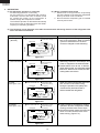
(3) The following circuit diagrams in the table show automatic defrosting function of the refrigerator with
timer and defrost thermostat.
Operation
1. Cooling
(Normal)
Electric diagram
Defrost thermostat ON
Compressor running
Timer motor running
Thermo. fuse
Defrost heater
TM
Defrost
thermostat (ON)
COMP
Compressor
Timer contact
Timer motor
SOURCE
Thermostat
Description
The integration timer integrates running
time of the compressor. When it reaches
cycle time of defrost timer, the timer
contact is changed to start defrosting.
Figure F-3.
Defrost thermostat ON
(Time 20 to 30 min.)
Thermo. fuse
Defrost heater
TM
Defrost
thermostat (ON)
COMP
Compressor
Timer motor stops
Timer contact
Thermostat
SOURCE
Compressor stops
Timer motor
2. Defrosting
The timer contact is changed to start
defrosting, the timer motor stops, and
power is supplied to the defrost heater.
It takes about 20 to 30 min. to defrost.
When little frosted, the defrosting takes
little time. When much frosted, the defrosting takes much time.
Figure F-4 .
Defrost thermostat OFF
Thermo. fuse
Defrost heater
TM
Defrost
thermostat (OFF)
COMP
Compressor
Thermostat
SOURCE
Compressor stops
Timer motor running
Timer contact
(Time approx. 5 min.)
Timer motor
3. Drain
When the defrost thermostat becomes
OFF, the timer motor starts running.
During the operation time (delay time
of defrost time) defrosted water is
drained outside the refrigerator.
Figure F-5.
Defrost thermostat OFF
SOURCE
Thermostat
Compressor running
Timer motor stops
Timer contact
Thermo. fuse
Defrost heater
TM
Defrost
thermostat (OFF)
Figure F-6.
12
COMP
Compressor
(Time approx. 5 min.)
Timer motor
4. Restart
Timer contact is changed to cooling
operation and the compressor starts
running and the timer motor stops.
Defrost thermostat contact becomes ON
when it’s cooled. And the timer motor
starts running. (Figure F-3.)
SJ-D59M/P60M
SJ-D64M/P65M
SJ-D69M/P70M
(4) As a reference to determine the causes of trouble, malfunction and phenomena are described below.
Refer to the following when repairing.
1. Disconnection of defrost heater
As off-cycle defrosting is performed, the defrosting time is extremely prolonged. Each time defrosting is
started, the freezer temperature rises and a portion of ice and stored foods are melted.
2. Melted thermo. fuse or opened-circuit due to the defect of defrost thermostat.
When the above mentioned trouble occurs in cooling operation, the timer motor does not run, defrosting
will not take place, and consequently freezing is caused. In the above mentioned condition, when the timer
shaft is turned by hand to defrost, the timer motor runs during the operation time. However, the motor stops
from the time when the contact is changed, and freezing causes.
NOTE:
As the thermo. fuse assembly is intended to prevent dangers, do not use it under shorted condition even
for a short period.
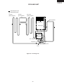
3. DEW PREVENTION
The hot pipe, namely D.P.-condenser, is arranged around the flange part of
cabinet and the C-partition plate, preventing dew from being generated on
the cabinet.
NOTE:
D.P.-condenser pipe may be felt hot if touched by hand while the
compressor is in operation.
If you are asked about this, please explain that the hot pipe serve to Hot pipe
prevent the dew generation.
Figure F-7
4. INSPECTION OF INITIAL STARTING
(1) Inspection of cooling unit
1. Set the temperature control knob to "MAX" and check that the compressor starts to operate.
2. Depress the door switch to run the fan and check that cool air is blown out of the cold air outlet of the
freezer and the refrigerator.
3. When the compressor does not work, check that the timer is not set to "defrost" position.
4 It takes about an hour and a half or two hours to put food in the refrigerator after starting operation.
NOTE:
After return the temperature control knob to "MED" position.
When the refrigerator is operated initially after installed, the compressor may vibrate excessively for 1 to 2
min. However, vibration becomes normal if it is continuously operated.
(2) Inspection of defrost device
Operate the refrigerator for 20 to 30 min. and then check the defrost device in the following procedures :
Allow 5 min. to restart the compressor since immediate starting after stopping will cause unsmooth operation.
1. Turn the timer shaft clockwise with a screw driver.
At this time, make certains the timer clinks and the compressor stops.
2. After more than 5 min., turn the shaft further to operate.
Make certain cooling operation is started again.
13
SJ-D59M/P60M
SJ-D64M/P65M
SJ-D69M/P70M
5. PLASMACLUSTER (Only for SJ-P60M,P65M,P70M)
(1) Plasmacluster is what thing.
The ionizer inside the refrigerator will release cluster ions, which are collective mass of positive and negative
ions, into the the freezer and refrigertor compartments.
The cluster ions reduce airborne fungus.
(2) Plasmacluster Panel
1.When the refrigerator will be operated, the Plasmacluster lamp of the
panel will ight up.
2.By pushing the button, the lamp gose out or lights up.
3.Under the lamp is lighting, Plasmacluster operation is controlled as
follows.
Plasmacluster panel
Lamp
Plasmacluster
Button
(3) Plasmacluster Control.
1.Plasmacluster operation will be performed when the following conditions
gather.
1) Lamp : Under lighting
2) Compressor : Under operation
3) Door : Closed
4) Within "The Plasmacluster operation time".
2.If the sum total of Plasmacluster operation time will reach at the set time ("The Plasmacluster operation Time") ,
Plasmacluster operation will stop.
3.After an operation stop, the Plasmacluster will be not operated during the set time ("The Plasmacluster operation
compulsive stop time") .
Time chart A
Compressor ON
F-fan motor Door
Plasmacluster t1
t2
t3
Time chart B
Compressor
F-fan motor Door
Plasmacluster t1
t2
t3
The Plasmacluster operation time = t1 + t2 + t3
14
SJ-D59M/P60M
SJ-D64M/P65M
SJ-D69M/P70M
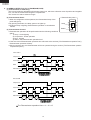
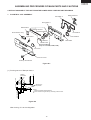
ASSEMBLING PROCEDURES OF MAIN PARTS AND CAUTIONS
CAUTION: DISCONNECT THE UNIT FROM THE POWER SUPPLY BEFORE ANY REPAIRING.
1. R-CONTROL COV. ASSEMBLY
Damper thermo.
RA sealer A
R air guider A
Defrost timer
Plasma harness
Plasma holder
RA sealer C
R fan thermo. ass'y
RA sealer B
Nylon band
Ionizer-K
Holder cover
(Only for SJ-P60M,P65M,P70M)
Fan cover
R-C box cover
R-temp. control knob
Figure A-1
5 +1 mm
3 +1 mm
Damper
thermostat
Less than 130 mm
(1) Forming sensor of Damper thermo.
Stick thermo.
cap. sealer
Less than 12 mm
25 + 2 mm
NOTE
Minimum bending radius is R5mm.
There should be no gas leak by reforming of sensor tube.
Figure A-2
After forming, fix it to the refrigerator.
15
Dial sealer
SJ-D59M/P60M
SJ-D64M/P65M
SJ-D69M/P70M
(2) Sticking of sealers to R air guider A.
[Front side]
[Back side]
RA sealer A
OVERLAP 15mm
OVERLAP 15mm
Dial sealer
RA sealer A
RA sealer B
RA sealer A
RA sealer C
RA sealer A
[Bottom side]
RA sealer A
RA sealer A
Figure A-3
(3) Fixing of the Ionizer-K.(Only for SJ-P60M, P65M, P70M)
(3)-1 Connect Ionizer-K and connector of the lead wire.
(3)-2 Insert Ionizer-K to Plasma holder.
(3)-3 Insert the (3)-2 assembly to R air guider A.
(3)-4 Insert Holder cover to (3)-3 assembly and fix by the paper tepe.
Plasma holder
Ionizer-K
Plasma harness
2P
2P
Ionizer-K
Holder cover
Connecter should insert surely.
Plasma holder
Ionizer-K
Plasma harness
2P
2P
2P
Plasma harness
R aire guider A
Paper tape W30X40mm
Paper tape W30X50mm
R aire guider A
B
Plasma holder
Ionizer-K
3
Holder cover
25
15
5
10
Plasma
harness
5
5
2P
R aire guider A
B
SEC. B-B
Figure A-4
16
5
SJ-D59M/P60M
SJ-D64M/P65M
SJ-D69M/P70M
(4) Fixing of Defrost timer, R fan thermo. ass'y cover to R-C box cover.
R fan thermo ass’y
R-C box cover
Nylon band
Defrost timer
G
10 + 5mm
Cut
G
R fan thermo.
ass’y
Nylon band
Fan cover
SEC. G-G
Figure A-5
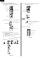
2. R LAMP BOX ASSEMBLY
R fan motor holder B
R-fan motor
Propeller fan 80
R fan motor holder A
Lamp socket (with lead wires for R-fan motor)
Fan clamp
Lamp 15W
Warning label
R lamp box
Figure A-6
17
SJ-D59M/P60M
SJ-D64M/P65M
SJ-D69M/P70M
(1) Fixing of Lamp and Lamp socket.
(1)-1 Screw Lamp 15W into Lamp socket.
(1)-2 Fix Lamp socket on R lamp box by tapping
screws.
(2)-4 Set Fan clamp to Propeller fan 80 and insert it
to the shaft of R-fan motor.
Tapping screw
F
Lamp socket
Fan clamp
ALUMINUM TAPE
Lamp 15W
Propeller fan 80
2.3 + 0.5mm
Shaft
R lamp box
Figure A-7
Detail of F
(1)-3 Insert the terminal of Lamp socket to R-fan motor.
Fan clamp
Slit of each Fan clamp and Propeller fan
should not be at same position.
DOUBLE CLAMPING WIRES
Slit
Lamp socket
Figure A-10
(3) Sticking Warning label.
Fan motor
Figure A-8
Warning label
(2) Fixing of R-fan motor and Fan
(2)-1 Set R-fan motor holder A to R lamp box by
tapping screw.
(2)-2 Set R-fan motor to R fan motor holder A by
machine screw.
(2)-3 Set R fan motor holder B to A.
Lamp 15W
Figure A-11
R fan motor holder B
R fan motor holder A
Propeller fan 80
R-fan motor
Figure A-9
18
SJ-D59M/P60M
SJ-D64M/P65M
SJ-D69M/P70M
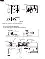
3. E.V COVER ASSEMBLY
U-sealer
handle
Motor
cushion
Fan motor
Propeller Fan 100
Fan motor
holder B
E.V cover sealer A
Fan clamp
Defrost thermo. ass’y
L-band C
E.V cover
Fan motor
holder A
E.V cover sealer C
Lead E.V-cover
ass’y
E.V cover sealer B
Fuse ass’y
F-thermostat
E.V cover
sealer D
(2 pieces)
Figure A-12
(1) Sticking of Sealers to E.V cover
E.V cover sealer B
E.V cover sealer A
Overlap 10mm(min)
Sticking start
Sticking start
Sticking start (a)
E.V cover
Sticking start (b)
E.V cover sealer D (b)
E.V cover sealer D (a)
[Front side]
[Back side]
Figure A-13
19
SJ-D59M/P60M
SJ-D64M/P65M
SJ-D69M/P70M
(2) Fixing of Fan motor and Fan
(2)-1 Stick U-sealer handle to Fan motor holder A.
Fan motor holder A
7 + 2mm
C
0 + 1mm
U-sealer handle
C
U-sealer handle
SEC. C-C
Figure A-14
(2)-2 Insert the terminals of Lead EV-cover ass'y to
R-fan motor.
(2)-3 Fix two Motor cushions to R-fan motor, and set it
at Fan motor holder A and B.
Then fix with Tapping screw.
Fan motor
holder B
Motor cushion
Fan motor
holder A
Tapping
screw
Fan motor
Lead EV-cover ass’y
RED
BROWN
Figure A-15
(2)-4 Set Fan clamp to Propeller fan 100 and insert
it to the shaft of Fan motor.
Fan clamp
D
Fan clamp
Slit
Propeller
fan 100
Slit of each Fan clamp
and Propeller fan
should not be at same position.
4 + 0.5mm
Shaft
Detail of D
Figure A-16
20
SJ-D59M/P60M
SJ-D64M/P65M
SJ-D69M/P70M
(3) Setting of Fan motor ass'y , Defrost thermo. ass'y and Fuse ass'y
Tapping screw
E.V cover
E.V cover
sealer C
L-band C
E
Lead E.Vcover ass’y
Tapping
screw
more than
3.5mm
Aluminum
tape
Set metal side below
Aluminum
tape
[FRONT SIDE]
F
Take out lead wire from
square hole to front, and
seal with E.V cover sealer C.
F
Fuse ass’y
Defrost
thermo. ass’y
E.V
cover
ATTENTION
Fuse
ass’y
cut
10 + 5mm
more than
3.5mm
Defrost
thermo. ass’y
E
L-band C
Not come out of claw
Turn up is lead wire
Sec. E-E
Sec. F-F
Figure A-17
(4) Inserting of pins
Fan motor 1 , 2
F-thermostat 3
(RED, inserted)
WIRE COLOR FOR FAN MOTOR
100-110V : WHITE
127V : YELLOW
220-240V : BLUE
F-thermostat 4
(BROWN, inserted)
Defrost thermo. 5
(PINK)
1
2
3
4
5
6
7
8
9
Fan motor 9
Fuse 8
(WHITE)
Defrost thermo. 6
(BLUE)
Fuse 7
(BLACK)
Note
Pins should be inserted surely,
and check by pulling it.
Figure A-18
After inserting, fix with vinyl tape.
Vinyl tape
60
mm
Figure A-19
21
SJ-D59M/P60M
SJ-D64M/P65M
SJ-D69M/P70M
(5) Setting of F-thermostat
20mm
(5)-1 Form capillary tube of F-thermostat.
R10mm
230mm
R10mm
Note
• Bending radius of
capillary tube should be
from R5mm to R10mm.
13mm
42mm
20mm
Figure A-20
(5)-2 Insert terminal of Lead EV-cover ass'y.
RED
(front side)
BROWN
(back side)
Figure A-21
(5)-3 Set to E.V cover.
F
SEC. F-F
F
Figure A-22
22
SJ-D59M/P60M
SJ-D64M/P65M
SJ-D69M/P70M
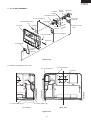
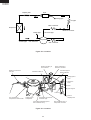
COOLING UNIT
Mark: Refrigerant flow
Mark: Brazing portion
Hot pipe L
(Side condenser)
Hot pipe
(DP-condenser)
Hot pipe R
(Side condenser)
Back condenser
Evaporator
Suction pipe
Sub. condenser
Compressor
Capillary tube
Dryer
Figure C-1. Cooling unit
23
SJ-D59M/P60M
SJ-D64M/P65M
SJ-D69M/P70M
Dryer
Capillary tube
Charge pipe
Hot pipe
Back condenser
Evaporator
Backcon connector
Connector pipe
Charge pipe
Compressor
Suction pipe
S.P. connector
Sub. condenser
Figure C-2. Location
Suction pipe ass'y to
S.P connector
Backcon connector to
Hot pipe
Back condenser to
Backcon connector
Connector pipe to
Back condenser
Absorbent rubber A
Compressor butyl
Charge pipe to
Dryer
Hot pipe to
Dryer
Dryer
Dryer support
L-band C
S.P Connector to
Compressor's suction tube
Charge pipe to
Compresser
Dryer to
Capillary tube
Compressor oil cooler to
Connector pipe
Compresser discharge pipe to
Sub condenser ass'y
Figure C-3. Location
24
Sub condenser ass'y to
Compresser oil cooler