1
INTRODUCTION
Thank you for buying the MZ-1 E14 SHARP MZ Disk Interface.
The MZ disk interface is used together with the MZ-1 F11 MZ disk drive, used
with the SHARP personal computer. Before using the M'Z disk interface, please
read this manual carefully to assure correct operation. Refer to the "Disk
BASIC Manual" or "MZ Disk BASIC Manual (5Z008)", if you have any questions.
The contents of this manual are subject to change without notice.
If the product is defective, please contact the store where you bought it.
SHARP is not responsible for damage incurred during, or as a result of, operation.
Caution
1. Do not use this unit where rapid increases or decreases in temperature occur
or in a humid or dusty environment. This unit consists of precision parts,
such as LSI circuits, that can be affected by the operating environment. Do
not expose the unit to direct sunlight.
2. Do not bump or drop this unit.
3. Be careful not to touch the connector with your hand. Static electricity can
destroy certain parts.
4. Special attention must be paid when handling disks. Refer to the MZ Disk
Drive MZ-1 F11 instruction manual and this manual for details.
5. We recommend that you make a copy of the original master disk and use the
copy. Store the original master disk in a safe place. (Refer to the MZ disk
BASIC manual included with this unit for the procedure for copying a disk.)
Disk protection
1. Follow the instructions on the protective envelope of the disk.
2. When disks are not in use, store them vertically in their envelopes in a disk
storage box.
3. Do not place disks near magnetic materials. This may destroy programs and
data on the disk.
CONTENTS
Overview . . . . . . . . . . . . . . . . . . . . . . . . . . . . . . . . . . . . . . . . . . . . . .
Parts of the Interface. . . . . . . . . . . . . . . . . . . . . . . . . . . . . . . . . . . . .. 2
Connection . . . . . . . . . . . . . . . . . . . . . . . . . . . . . . . . . . . . . . . . . . .. 3
Pinout of Connectors . . . . . . . . . . . . . . . . . . . . . . . . . . . . . . . . . . . . . 7
Specifications . . . . . . . . . . . . . . . . . . . . . . . . . . . . . . . . . . . . . . . . . . 8
OVERVIEW
This interface connects an MZ-700 series personal computer and the MZ-1 F11
disk drive. The interface reads the system software (BASIC (5Z-008) etc.) with
built-in IPL ROM. (This takes about 8 seconds, not including AUTO RUN.)
Three types of files can be cataloged on a MZ disk:
1. BASIC text file (program)
2. Sequential data
3. Machine-language file (system software, etc.)
Up to 32 files can be cataloged on one side of a disk*. If only one program (file)
is cataloged per side, the maximum storage capacity is 64K bytes. As the number
of files increases, the storage capacity decreases. This is because a gap is required
between files. Sequential data files are blocked and cataloged in units of 1 K
bytes; the maximum storage capacity of a disk side is about 40K bytes.
*The number of files equals the number of programs or group data entries.
-1-
~
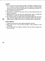
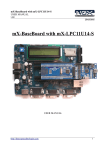
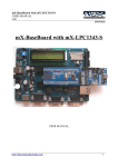
PARTS OF THE INTERFACE
Connector for 26-pin cable from the MZ-1 F11 disk drive
Connector guide pin
(Between 6th and 7th pin)
Connector to MZ-700
series computer
Tabs for fixing the interface to the computer
-
2 -
CONNECTION
To connect the MZ disk drive to an MZ-700 series computer, perform the
following.
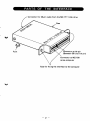
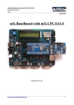
1. Remove the data recorder, or the cover (for MZ-711 or MZ-710).
1) Turn off the power switch of the computer and unplug the AC cord.
Remove the two screws holding the data recorder from the left rear side of
the computer. Lift the data recorder out of its mounting. (Figure 1)
2) Remove the connector (CN1) between the data recorder and the MZ-700
series computer. (Figure 1 )
Data recorder
Figure 1
Note: When the data recorder is to be used, connect it to the MZ-1 F11 connector. (See Figure 4 for details.)
-
3 -
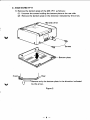
2. Jnstall the MZ·1 F11
1) Remove the bottom plate of the MZ·1 F11 as follows:
(1) Unscrew the screws holding the bottom plate at the rear side.
(2) Remove the bottom plate in the direction indicated by the arrow.
Bottom plate
F.ont
Nee
eb
a
Roa ,
((===J Remove only the bottom plate in the direction
V
by the arrow.
Figure 2
-4-
indicated
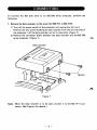
2) Connect CN2 (from the bottom of MZ-1 F11) to the conneC1Dt ·of the
computer main unit that was originally connected to the data recorder.
(Figure 3)
3) Mount the MZ-1 F11 where the data recorder was originally, using the
screws that held the data recorder in place. (Figure 3)
Figure 3
-5-
;
Connector cover
Figure 4
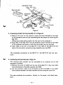
3. Connecting the MZ-1E14 and the MZ-1F11 (Figure 4)
1) Remove the cover for the external output terminal (I/O BUS) at the back
of the computer main unit by unscrewing the two screws for mounting the
MZ-1 F11.
(These two screws will be used to fix this unit to the computer.)
2) Plug CNS of the MZ-1 E14 into the external output terminal at the back
of the computer and secure it with the two screws you just removed.
3) Insert CN3 at the rear of the MZ-1F11 into CN4 of the MZ-1E14 and
secure the connection using the screws originally securing CN3.
This completes connection of the MZ-1F11, the MZ-1E14 and the computer.
V
4. Connecting the Data Recorder (Figure 4)
The removed data recorder can be connected as an external unit to the
computer as follows:
1) Remove the cover for CN6 from the rear of the MZ-1 F11, then insert CN1
from the bottom of the data recorder into CN6.
2) Use the extension cable to be connected to CN1 and CN6, if you prefer
more distance between the data recorder and the computer main unit.
This step completes the procedure. Switch on the power, and check operation.
-6-
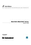
PINOUT OF CONNECTORS
To computer
~
-:.;"'t;
<::.<::.
{"
of"
co~<b
~
!'o......<::.
~"'t'
....~"'fS
"
• -.:- lA-se.cL
"
COMPONENT SIDE
49
A15
47
A14
45
A13
43
A12
41
All
Al0
39
37
A9
A8
35
A7
33
31
A6
29
A5
27
A4
A3
25
A2
23
21
Al
19
AO
17
BUS 4>
15
D7
13
D6
11
D5
9
D4
7
D3
D2
5
3
Dl
1
DO
(J
~
From MZ-1 F11
PATTERN SIDE
NMI
50
48
EXINT
GND
46
MERQ
44
42
GND
lORQ
40
GND
38
RD
36
34
GND
""WJ=f
32
EXWAIT
30
M4
28
GND
26
24
RACT
EXRESET
22
RESET
20
GND
18
GND
16
14
GND
GND
12
GND
10
GND
8
GND
6
4
GND
GND
2
~
·
F
•
•
,
"
~
COMPONENT SIDE
+5V
25
Sl
23
21
RESET
19
4>
17
Ml
D7
15
D6
13
D5
11
D4
9
D3
7
D2
5
Dl
3
DO
1
,.
-7-
PATTERN SIDE
26
GND
24
CE
22
SO
20
RD
IORQ
18
16
GND
14
GND
12
GND
10
GND
GND
8
GND
6
4
GND
GND
2
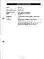
SPECIFICATIONS
Model
MZ-l E14
Operating power
+5 VDC ± 5%
Operating temperature
1Q°C - 35°C
Operating humidity
ROM
IC
20% - 80% (no condensation)
IPL ROM (4K bytes), 1 chip
9 chips
Dimensions
77 mm (width) x 125 mm (depth) x 16 mm (height)
Weight
220 g
Accessories
MZ-700 BASIC (5Z008)/utilities master disk ........... 1
MZ blank disk .......................................................... 1
Extension cable for Data Recorder ........................... 1
MZ-700 Disk BASIC Manual, MZ-700 MZ disk
BASIC Manual (5Z008), instruction manual
-8-
****
NOTES
****
SHARP CORPORATION
OSAKA, JAPAN
Printed in Japan
Gedruckt in Japan
Imprime au Japan
Stampato in Giappone
© 1984
SHARP CORPORATION
4G 2.10 (TINSE1215ACZZ)