1
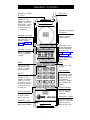
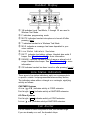
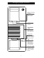
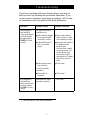
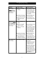
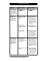
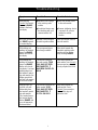
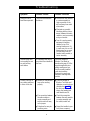
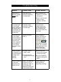
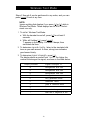
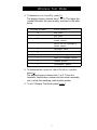
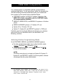
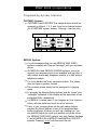
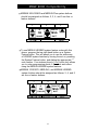
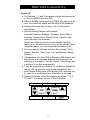
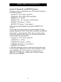
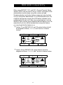
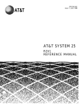
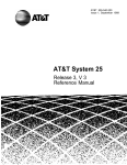
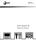
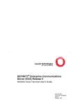
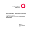
AT&T
MDW 9000 Wireless
Telephone
Quick Reference
Contents
1
Handset Controls
Handset Display
Line Status Indicators
Call Alerter
Charging Cradle Controls
Troubleshooting
Wireless Test Mode
MDW 9000 Compatibility
2
2
2
3
4-9
10-11
12-17
Remember to press the [ On/Off ] button to turn on your wireless
phone before pressing any other button.
Help!
If you need assistance when using your wireless phone with a
PARTNER, MERLIN, or MERLIN LEGEND system in the continental U.S., call 1 800 628-2888. For all other systems, follow
the procedure you normally use to get support for your communications system. Outside the continental U.S., contact your
AT&T Representative or local Authorized Dealer.
AT&T
Handset Controls
Antenna
Headset On/Off
Button
Press to turn the
headset on. ON
appears in handset
display. To turn off,
press again. Turn on
to make or answer
a call, and turn off
to “hang up.”
Battery Charging
Contacts
Handset battery
charges through
these contacts.
Handset Display
Displays status of
lines and range. For
detailed description, see “Handset
Display” on next
page.
Outside Line/
Programmable/
Intercom/Drop
Buttons (6)
Volume Control
Press +/- to adjust
volume of earpiece
or ringer.
See “MDW 9000
Compatibility”
beginning on page
12 for system button
assignments.
Mute
Hold
Press to turn the
microphone off for
privacy of internal
communications.
Press to put a call
on hold.
Feat (Feature)
Press to enter
programming mode
or to use dial-code
features. Not used
on System 25,
System 75, System
85, or DEFINITY®
system.
On/Off
Press to turn the
handset on. ON
appears in handset
display To turn off,
press again. Turn on
to make or answer
a call, and turn off
to “hang up.”
Trans (Transfer)
Press to transfer
a call to another
extension.
Conf (Conference)
Press to conference
in (add) another
party to your call.
Extension Label
Write the extension
number on this label
using a pencil or
ball-point pen only.
Headset Jack
Insert headset cord
when using headset.
1
Handset Display
➀ 18 indicates Local Test Mode; 1 through 10 are used in
➁
➂
Wireless Test Mode.
P indicates programming mode.
MUTE indicates handset microphone is turned off after
pressing [ Mute ].
➃ T indicates handset is in Wireless Test Mode.
➄ MSG indicates a message has been deposited in your
voice mailbox.
➅ Line Status Indicators. See below.
➆ BATT indicates low battery voltage, Handset also emits 2
➇
beeps. See “Troubleshooting” for more information.
RANGE indicates handset is out of range or almost out of
range. Handset also beeps. See “Troubleshooting” for more
information.
➈ ON indicates handset has been turned on after pressing [ On/Off ].
Line Status Indicators
There are six line status indicators; each one corresponds to
a specific outside line/programmable/intercom/drop button,
The indicators show either a triangle or a rectangle, signifying
activity as follows:
PARTNER Systems
Arrow ( ▲ or ▼ ) indicates activity at YOUR extension.
Rectangle (
) indicates activity at ANOTHER extension.
All Other Systems
Rectangle (
) indicates activity at YOUR extension.
Arrow ( ▲ or ▼ ) indicates activity at ANOTHER extension.
Call Alerter
If a call comes in while the phone is idle, the handset rings.
If you are already on a call, the handset chirps.
2
Charging Cradle Controls
AT&T
Battery Charging
Contacts
Handset battery
charges through
these contacts.
Handset Hook
Rotate for wall
mounting.
Spare Battery
Compartment
Cover
Open to insert or
remove optional
spare battery pack.
Charge LED
Lights when handset
is properly placed in
cradle for charging.
Ext. 16
Charge
Spare
Charge
Spare Charge
LED
Lights when spare
battery pack is
properly placed in
cradle's spare battery compartment.
Extension Label
Write this phone's
extension number
on this label using a
pencil or ball-point
pen only.
3
Troubleshooting
If you have a problem with your wireless phone, you may be
able to solve it by following the procedures listed here. If you
cannot resolve a problem using these procedures, call for help
as described on the front panel of this Quick Reference.
Symptom
Possible Causes
After plugging the
radio module or
carrier assembly into
an electrical outlet,
the radio module’s
POWER LED does
not light.
For single radio module
installations only:
Possible Solutions
■
Radio module is plugged
into an electrical outlet
controlled by a switch.
■
Plug the radio module’s
power cord into an outlet
not controlled by a switch.
■
Radio module’s power
cord is not inserted
properly.
■
Unplug the radio module’s
AC adapter from the
electrical outlet.
Disconnect then carefully
re-insert the power cord
into the left side of the
radio module. Plug the
radio module’s AC adapter
back into the electrical
outlet.
■
Radio module’s power
cord is defective.
■
Call for help.*
■
Call for help.*
For carrier assembly
installations:
■
After plugging the
radio module or
carrier assembly into
an electrical outlet,
the PASS LED does
not light.
Radio module is
inoperable.
Radio module or carrier
assembly is inoperable.
* See front panel of this Quick Reference.
4
Call for help.*
Troubleshooting
Symptom
Possible Causes
After pressing
[ On/Off ], dial tone iS
not heard and handset display does not
show anything.
■
Battery is not charged
sufficiently.
■
Place handset in charging
cradle for 12 hours. Or, if
you have a fully charged
(14 hours) spare battery,
use it to replace the battery
in the handset.
■
Handset is out of range of
its matching radio module.
■
Move the handset closer
to the radio module.
■
Telephone line cord is not
plugged into the radio
module.
■
Plug the telephone line
cord into the radio module.
■
There is no battery in the
handset.
■
Insert battery in handset.
■
Battery is not inserted
properly in handset.
■
Make sure battery is inserted
properly in handset.
■
Battery is not charged
sufficiently.
■
Place handset in charging
cradle for 12 hours. Or, if
you have a fully charged
(14 hours) spare battery,
use it to replace the
battery in the handset.
■
Handset is out of range of
its matching radio module.
■
Move the handset closer
to the radio module.
■
There is interference from
another electrical device
(microwave) or metal walls.
■
Remove electrical device
causing interference or move
handset to another location.
After pressing [ On/Off ],
dial tone is not heard
and the RADIO LED
on the radio module
does not light.
BATT appears in the
handset display.
Battery requires recharging.
Possible Solutions
You have 1-2 minutes of talk
time left. Either:
■ Complete your call, turn the
handset off, and recharge
the battery (12 hours).
■
5
If you have a fully charged
(14 hours) spare battery,
place your call on Hold.
Swap the batteries. Wait 6
to 10 seconds, then turn the
handset on and proceed as
you would for any call
placed on Hold.
Troubleshooting
Symptom
Possible Causes
Possible Solutions
You can hear the
party on the other
end, but they cannot
hear you. MUTE
appears in the handset display.
The [ Mute ] button was
pressed inadvertently.
Press [ Mute ] again to turn
off the mute feature.
Charge LED on
charging cradle
does not light when
handset is placed
in charging cradle.
■
Handset is not seated
properly in charging
cradle.
■
Make sure handset is
seated properly in charging cradle. Also check
that there are no obstructions on the handset or
charging cradle contacts.
Try cleaning contacts with
a soft eraser.
■
Charging cradle is
plugged into an electrical
outlet controlled by a
switch.
■
Plug charging cradle
power supply into an outlet
not controlled by a switch.
■
Handset battery is
defective or dead.
■
If you have a fully charged
(14 hours) spare battery,
use it to replace the
battery in the handset. Or,
order a new battery. If the
Charge LED still does not
light, call for help.*
■
Spare battery is not
seated properly in
charging cradle battery
compartment.
■
Make sure spare battery is
seated properly in the
charging cradle compartment. Also check that
there are no obstructions
on the battery or charging
cradle contacts. Try cleaning contacts with a soft
eraser.
■
Spare battery is defective
or dead.
■
Swap the spare battery
with the handset battery to
see if the Spare Charge
LED Iights. If it lights, order
a new battery to replace
the spare. If it does not
light, call for help.*
Spare Charge LED
on charging cradle
does not light when
spare battery is
placed in charging
cradle battery compartment.
* See-front panel of this Quick Reference.
6
Troubleshooting
Possible Solutions
Symptom
Possible Causes
After pressing
[ On/Off ], the handset
beeps and RANGE
shows in the handset display.
■
Handset is out of range
of its matching radio
module.
■
Move the handset closer
to the radio module.
■
An electrical device may
be interfering with your
communications link.
■
Remove interfering device
or power it off, or move
handset to another
location.
No ring on incoming
call, RANGE appears
in handset display.
Handset is out of range of
its matching radio module.
Move the handset closer to
the radio module.
While talking and
walking, the handset
beeps and RANGE
flashes in the handset display.
You are approaching an
out of range condition.
Move back towards the
handset’s matching radio
module until the display
stops showing RANGE.
While talking and
walking, the handset
beeps and RANGE
flashes in the handset display. You keep
walking away from
the handset’s matching radio module, the
display goes blank,
and your call appears
to be disconnected.
You are out of range of
the radio module. YOUR
CALL HAS NOT BEEN
DISCONNECTED. IT
HAS BEEN PLACED ON
HOLD.
Move back towards the
radio module. Press [On/Off ],
then proceed as you would
for any call placed on Hold.
After placing a call
on Hold, you walk
further away from
the handset’s matching radio module.
Your handset beeps,
the handset display
flashes RANGE, and
your call appears to
be disconnected.
You are out of range of the
radio module. YOUR
CALL HAS NOT BEEN
DISCONNECTED. IT
IS STILL ON HOLD.
Move back towards the
radio module. Press
[ On/Off ], then proceed as
you would for any call
placed on Hold.
7
Troubleshooting
Symptom
Possible Causes
Range for calls is
lower than expected.
There are environmental
limitations.
Possible Solutions
■
Reinstall the radio module
or carrier assembly as
high as possible on the
wall and away from metal
obstructions.
■
Eliminate any possible
interfering devices (microwaves) between the radio
module or carrier assembly
and your handset.
■
Turn off or unplug nearby
equipment (computer,
modem) to see if it is
causing interference. If it
is, make sure it is on a different power line or move
it further away from the
handset, radio module, or
carrier assembly.
Place the handset in
Wireless Test Mode as
described on page 10. If the
signal strength and voice
quality readings are low,
look for a newly installed
radio device nearby.
Remove it or move your
handset’s matching radio
module.
Handset range and
voice quality are not
as good as they
were before.
A competing radio device
may have been installed in
the area.
Volume is too low at
any setting and there
is noise on the line.
■
Handset or radio module
may not be working
properly.
■
Place the handset in
Wireless Test Mode and
determine sound clarity as
described on page 10. If
the dial tone is clear and
strong, the handset and
radio module are OK.
■
The connection between
the radio module or
carrier assembly and
switch/control unit may
not be proper.
■
Check the connection
between the radio module
or carrier assembly and
the switch/control unit.
■
Telephone line may be
producing noise.
■
Report line trouble to your
local phone company.
8
Troubleshooting
Symptom
Possible Causes
Possible Solutions
Handset does not
respond to repeated
[ On/Off ] button
presses.
There was a recent
occurrence of lightning,
or a power failure.
■
Remove battery from
handset for 10 seconds,
then replace it.
■
Check to see if the radio
module or carrier
assembly is receiving
power.
Your business has 2
or more wireless
phones installed and
all handsets seem to
have developed interference problems at
the same time.
There was a recent
occurrence of lightning,
or a power failure.
Unplug the carrier
assembly’s power cord
from the electrical outlet.
Wait 10 seconds, then
reconnect the power cord
to the outlet.
Your business has 2
or more wireless
phones installed and
you (a) cannot determine which radio
module corresponds
to your handset or
(b) are confused
about which handset
is yours.
Handsets have been
mixed up.
Place the handset in
Wireless Test Mode and
determine the terminal
identification number as
described on page 11. This
is the slot number of the
radio module in the carrier
assembly that corresponds
to the handset, and it is the
terminal identification
number of the handset.
Handset range and/
or voice quality is not
as good as expected
in multiple carrier
assembly
installation.
■
Coverage zones of
carriers overlap.
■
You moved into the
coverage zone of another
carrier.
You are on a call and
you hear radio
interference when
another call rings.
System in Key Mode has
all lines set to ring. An
incoming call "wakes up"
all of the other radio
modules at the same time
to ring the other phones.
9
■
Reinstall one of the
carriers so the coverage
zones do not overlap.
■
Move back towards the
handset’s matching radio
module.
Program some of the
wireless phones for
Delayed Ring or No Ring.
Wireless Test Mode
Steps 2 through 5 can be performed in any order, and you can
press [ On/Off ] to exit at any time.
NOTE:
Ignore anything that displays if you press [ 4 ] or [ 5 ] while in
Wireless Test Mode. These displays are for AT&T Technicians’ use only.
1. To enter Wireless Test Mode:
a. With the handset turned off, press [ 9 ] for at least 5
seconds.
b. While still holding [ 9 ], press [ On/Off ].
T appears in the display. You hear 2 beeps, then
simulated dial tone.
2. To determine sound clarity, listen to the simulated dial
tone as you walk around. A clear, strong tone indicates
good sound clarity.
3. To determine signal strength, press [ 1 ].
The display shows a number from 1 to 10. The higher the
number the stronger the signal, as shown in the table below:
Signal Strength Is
Display Number
10
Strong/almost error free
9
Strong/almost error free
8
Strong/almost error free
7
Very good/some errors
6
Very good/some errors
5
Good/more errors
4
Good to Fair/more errors
3
Fair/more errors
2
Near end of range
1
Near end of range/loss of link
10
Wireless Test Mode
4. To determine voice quality, press [ 2 ].
The display shows a number from 1 to 10. The higher the
number the better the voice quality, as shown in the table
below:
Voice Quality Is
Display Number
10
Very good
9
Very good
8
Errors, but not noticeable in
normal speech
7
Errors, but not noticeable in
normal speech
6
Noticeable noise
5
Noticeable noise
4
Noisy but intelligible speech
3
Noisy but intelligible speech
2
Garbled speech
1
Unintelligible speech
5. To determine the terminal identification number,
press [ 3 ].
The display shows a number from 1 to 6. This is the
handset’s identification number and the carrier assembly
slot in which the matching radio module resides.
6. To exit Wireless Test Mode, press [ On/Off ].
11
MDW 9000 Compatibility
Your wireless phone is compatible with the communications
systems listed below. To use your phone, follow the programming
and call handling instructions that come with your communications system for the specific phone identified below.
®
■ PARTNER systems: the MLC-6 Cordless Telephone; the
MDW 9000 is fully compatible with the PARTNER family
of communications systems.
®
■
MERLIN , MERLIN Plus, and MERLIN II systems: a 5-button
phone.
®
■ MERLIN LEGEND systems: a 10-button ATL set.
■
System 25: a 10-button ATL set.
■
System 75, System 85, and DEFINITY systems*: a 7303s set.
Carefully note the functional differences between your wireless
phone and the one identified above, as described in the
following sections.
Entering Station Programming Mode
On all PARTNER, MERLIN, and MERLIN LEGEND systems:
■ To enter programming mode, turn on the handset, press
[ Intercom ], then press [ Feat ] followed by [ 0 ] [ 0 ].
■ To exit programming mode, press [ Feat ] followed by [ 0 ] [ 0 ]
or turn off the handset.
NOTE:
The above instructions do not apply on System 25, System 75,
System 85, and DEFINlTY systems. On those systems, features
are assigned by the system administrator.
* For DEFINITY G3V3 systems, you can administer the system for the
MDW 9000 telephone (rather than a 7303s set) and follow the user’s
instructions in the MDW 9000 Wireless Telephone User’s Guide,
order number 555-230-768.
12
MDW 9000 Compatibility
Programming System Features
PARTNER Systems:
■ PARTNER II and PARTNER Plus system buttons should be
assigned as follows; 1, 2, 3, and 4 are line or feature buttons
(for a PARTNER system, buttons 1 through 4 are line only):
1
3
2
18
PMUTE
ON
MSG
RANGE
BATT
4
MERLIN Systems:
■ It is recommended that you use MERLIN 206/410/820
systems installed with Feature Package 2 with your wireless
phone.
■ On MERLIN II and MERLIN LEGEND systems, you must
connect your wireless phone to an available jack on either a
408 outside line/analog telephone module or a 008 analog
.
telephone module.
■ You must disable the Voice Announce feature. This phone
does not have a speaker function.
■ The wireless phone should not be assigned to a paging
group.
■ To program the Ringing Option feature, use the “arrow” and
“rectangle” indicators in the display as the equivalent of red
and green LEDs, respectively.
■ For MERLIN II system users, if you program an Auto Intercom
button, idle line preference must be set to intercom.
■ If any of your incoming lines has the call waiting feature,
program the Recall feature on one of the programmable
buttons and press it before you pick up a waiting call. You
can dial #50 before you pick up a waiting call on the follow
ing: MERLIN 206/410/820 systems only with Feature Package
2, and all MERLIN Plus, MERLIN II and MERLIN 1030/3070
systems. Pressing [ On/Off ] will disconnect the call.
13
MDW 9000 Compatibility
■
MERLIN 206/410/820 and MERLIN Plus system buttons
should be assigned as follows; 2, 3, 4, and 5 are line or
feature buttons:
5
4
3
18
PMUTE
ON
MSG
RANGE
BATT
2
To use MERLIN LEGEND system feature codes with this
phone, program the top right-hand button as a System
Feature button. This will permit you to use the wide array
of LEGEND system features by turning the set on, pressing
the System Feature button, and dialing the appropriate “*”
code number. Your wireless phone’s [ Feat ] button only allows
you to enter programming mode. It does not work when
using the MERLIN LEGEND system features.
■ MERLIN 1030/3070, MERLIN II, and MERLIN LEGEND
system buttons should be assigned as follows; 3, 4, and 5
are line or feature buttons:
■
5
4
3
18
PMUTE
ON
MSG
RANGE
BATT
14
MDW 9000 Compatibility
System 25:
■ For Releases 1, 2, and 3, this phone must be administered as
a 10-button MERLIN set (type 303).
■ Either a TN762B Hybrid pack or a ZTN79 ATL pack must be
used to connect the switch and the MDW 9000 telephone.
■ Assigning features may be done only by the system
administrator.
■ Use the following features with caution:
Automatic Intercom, Bridging, Coverage, Direct Station
Selection, Personal Line, Pooled Facility, Send All Calls
(use with single ring reminder).
Since these features provide visual indication that the
feature is on, be aware that if you turn off the handset when
using that feature, you may forget that the feature is on.
■ Do not assign the following features: Auto Answer, Scroll,
Inspect, Directory, Next, Local, Call, and Manual Callback
Queuing.
■ If programming the Flex DSS or Repertory Dial feature, dial
the number to be recorded and push the button you are
assigning to the feature. You will receive 3 short beeps and
a dial tone to confirm programming.
■ If you are programming numbers for the Station Speed Dial
feature, dial the numbers to be stored then dial the Personal Speed Dialing code (#20 through #39), including the
#. Listen for a confirmation tone followed by a dial tone.
■
System 25 buttons should be assigned as follows; 7, 8, 9,
10, and 11 are system access or feature buttons:
9
11
8
7
18
PMUTE
ON
MSG
RANGE
BATT
10
15
MDW 9000 Compatibility
System 75, System 85, and DEFINITY Systems:
This phone must be administered as a 7303s Hybrid terminal for
the following systems:
■ System 75 - R1V1, R1V2, and R1V3
■ System 85 - R2V1, R2V2, R2V3, and R2V4
■ DEFINITY G1 - (R1V4)
■ DEFINITY G2 - G2.1 and G2.2 - (R2V5, R2V6)
■ DEFINITY G3 Version 1 - (R1V5)
■ DEFINITY G3 Version 1.1 and Version 2
Native terminal administration is provided in DEFINITY G3
Version 3.
On the older switch types that do not accommodate Universal
modules (System 85 - R2V1, R2V2, R2V3, and R2V4), an ANN17B
Hybrid pack in conjunction with a DS-1 carrier must be used to
connect the switch and this phone. On the newer switches that
accommodate Universal modules:
■ System 75 - R1V1, R1V2, and R1V3
■ DEFINITY G1 - (R1V4)
■ DEFINITY G3 Version 1 - (R1V5)
DEFINlTY G3 Version 1.1 and Version 2
■ DEFINITY G3 Version 3
a TN762B Hybrid pack must be used with the Universal carrier
for this purpose. Depending upon the actual hardware configuration, DEFINITY G2 - G2.1 and G2.2 may utilize either an
ANN17B or TN762B pack. In either case, the latest vintage
packs are recommended.
■
16
MDW 9000 Compatibility
When using DEFINITY G2.1 and G2.2, General Terminal Administration (GTA) may be used to set up “custom” set types so that
administration may be done using that custom set type.
Set administration and button feature assignment may be done
only by the system administrator. It is recommended not to use
a feature that requires visuals (the LCD feature indicator) to be
updated while the set is off. Also, since some features, such as
Send All Calls, provide visual indication that the feature is on, be
aware that if you turn off the handset when using that feature,
you may forget that the feature is on.
■
System 75 and DEFINITY G1 and G3 system buttons should
be assigned as follows; 1, 2, 3, 4, and 5 are line or feature
buttons:
3
2
18
PMUTE
ON
MSG
RANGE
BATT
4
5
■
7
System 85 and DEFINITY G2 system buttons should be
assigned as follows: 3, 4, 5, 6, and 7 are line or feature buttons:
5
7
4
3
18
PMUTE
ON
MSG
RANGE
BATT
6
17
Notes
PARTNER, MERLIN, MERLIN LEGEND, and DEFINITY are registered trademarks
of AT&T.
AT&T 503-801-110
Comcode 107168908
AT&T
Issue 2 (January 1995)
Copyright © 1995 AT&T