1
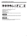
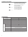
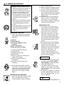
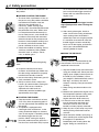
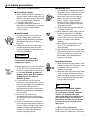
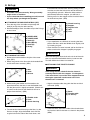
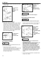
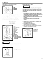
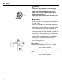
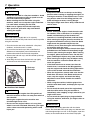
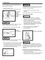
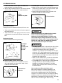
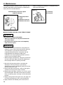
115 37 95-79 (006)
OWNER’S MANUAL
BRUSHCUTTERS
BK3410FL / BK3410FL-S
BK4310FL / BK4310FL-S
Caution
• Before using our brushcutter, please
read this manual carefully to understand
the proper use of your unit.
• Keep this manual handy.
SAFETY FIRST
Instructions contained in warnings within this manual marked with a
symbol concern critical points which must be taken into
consideration to prevent possible serious bodily injury, and for this
reason you are requested to read all such instructions carefully and
follow them without fail.
■ NOTES ON TYPES OF WARNINGS IN THE MANUAL
WARNING
This mark indicates instructions which must be followed in order to
prevent accidents which could lead to serious bodily injury or death.
IMPORTANT
This mark indicates instructions which must be followed, or it leads to
mechanical failure, breakdown, or damage.
NOTE
This mark indicates hints or directions useful in the use of the product.
Contents
1.
2.
3.
4.
5.
6.
7.
8.
9.
10
2
Warning labels on the machine …………………3
Symbols on the machine …………………………4
Specifications ………………………………………4
Safety precautions …………………………………5
Set up ………………………………………………9
Fuel ………………………………………………12
Operation …………………………………………13
Maintenance ………………………………………17
Trouble shooting …………………………………21
Disposal ……………………………………………21
1. Warning labels on the machine
15m (50ft)
(1)
(2)
(3)
(4)
(5)
(6)
(7)
(1) Read owner’s manual before operating this machine.
(2) Wear head, eye and ear protection.
(3) Wear foot protection.
(4) Wear gloves.
(5) Beware of thrown objects.
(6) Warning / Attention
(7) Keep all children, bystanders and helpers 15 meters away from the machine.
IMPORTANT
If warning label peels off or becomes soiled and impossible to read, you should contact
the dealer from which you purchased the product to order new labels and affix them in
the required location(s).
WARNING
Never modify your machine.
We won’t warrant the machine, if you use the remodeled brushcutter or if you
don’t observe the proper usage written in the manual.
3
2. Symbols on the machine
For safe operation and maintenance, symbols are
carved in relief on the machine. According to these
indications, please be careful not to take a mistake.
(a) The port to refuel the "MIX GASOLINE"
Position: FUEL TANK CAP
(b) The direction to close the choke
Position: AIR CLEANER COVER
(c) The direction to open the choke
Position: AIR CLEANER COVER
3. Specifications
Name/Type
Handle Type
Machine Weight (✽1)
kg
Outward Size (L x W x H) mm
Outer pipe
mm
Applied Head
Power Transmission Method
Reduction Rate
Blade Rotating Direction
Type
Displacement Volume cc
Fuel Tank Capacity
Fuel Used
Lubricating Oil Used
Engine
Mixing rate
Carburetor
Sparking Method
Spark Plug
Starting Method
Stopping Method
ZENOAH Knapsack Brushcutter
BK3410FL/BK3410FL-S
BK4310FL/BK4310FL-S
Loop
8.8
9.0
315 x 270 x 410
1500 (FL)/1400 (FL-S) ø26
2-teeth blade(12”), 4-teeth blade, 8-teeth blade, round saw blade(10”), line head
Automatic centrifugal clutch, spiral gear
1.235 (21 : 17)
Counterclockwise (from operator' s view)
Single cylinder air cooling 2-cycle gasoline engine
33.6
41.5
1.3
Lubricating oil mixed gasoline
2-cycle engine oil
when using ZENOAH genuine oil (FC grade): 50:1
when using market oil (FB grade): 25:1
float, piston valve
CDI
Champion RCJ-6Y
Recoil starter
Sparking Circuit Primary Short (push button)
(✽1) excluding cutting head, shoulder strap and fuel
Please note that due to improvement, detailed specifications of the product may differ from the information herein.
4
4. Safety precautions
1. Read this manual carefully until you
completely understand and follow all
safety and operating instructions.
2. Keep this manual handy so that you
may refer to it later whenever any
questions arise. Also note, if you
have any questions which cannot be
answered herein, contact the dealer
from whom you purchased the
product.
3. Always be sure to include this manual
when selling, lending, or otherwise
transferring the ownership of this
product.
4. Never allow children or anyone unable
to fully understand the directions
given in the manual to use the
machine.
■ WORKING CONDITION
1. When using the product, you should
wear proper clothing and protective
equipment.
(1) Helmet
(2) Ear protectors
(3) Protection goggles or face
protector
(4) Thick work gloves
(5) Non-slip-sole work boots
2. And you should carry with you.
(1) Attached tools
(2) Properly reserved fuel
(3) Spare blade
(4) Things to notify your working area
(rope, warning signs)
(5) Whistle (for collaboration or
emergency)
(6) Hatchet or saw (for removal of
obstacles)
3. Do not wear loose clothing, jewelry,
short trousers, sandals, or go barefoot.
Do not wear anything which might be
caught by a moving part of the unit.
Secure hair so it is above shoulder
length.
■ WORKING CIRCUMSTANCE
1. Never start the engine inside a closed
room or building. Exhaust gases
contain dangerous carbon monoxide.
2. Never use the product,
(1) When the ground is slippery or when
you can’t maintain a steady posture.
(2) At night, at times of heavy fog, or at
any other times when your field of
vision might be limited and it would be
difficult to gain a clear view of the
working area.
(3) During rain storms, during lightning
storms, at times of strong or galeforce winds, or at any other times
when weather conditions might make
it unsafe to use the product.
■ WORKING PLAN
1. You should never use the product
when under the influence of alcohol,
when suffering from exhaustion or
lack of sleep, when suffering from
drowsiness as a result of having
taken cold medicine or at any other
time when a possibility exists that
your judgment might be impaired or
that you might not be able to operate
the product properly and in a safe
manner.
2. When planning your work schedule,
allow plenty of time to rest. Limit the
amount of time over which the
product is to be used continuously to
somewhere around 30 ~ 40 minutes
per session, and take 10 ~ 20
minutes of rest between work
sessions. Also try to keep the total
amount of work performed in a single
day under 2 hours or less.
WARNING
1. If you don’t observe the working time,
or working manner (See “USING
THE PRODUCT”), Repetitive Stress
Injury (RSI) could occur.
If you feel discomfort, redness and
swelling of your fingers or any other
part of your body, see a doctor before
getting worse.
2. To avoid noise complaints, in general,
operate product between 8 a.m. and
5 p.m. on weekdays and 9 a.m. to 5
p.m. on weekends.
NOTE
Check and follow the local regulations as
5
4. Safety precautions
to sound level and hours of operations for
the product.
■ BEFORE STARTING THE ENGINE
1. The area within a perimeter of 15 m of
the person using the product should be
considered a hazardous area into
which no one should enter. If
necessary, yellow warning rope,
warning signs should be placed around
the perimeter of the area. When work
is to be performed simultaneously by
two or more persons, care should also
be taken to constantly look around or
otherwise check for the presence and
locations of other people working so as
to maintain a distance between each
person sufficient to ensure safety.
2. Check the condition of working area to
avoid any accident by hitting hidden
obstacles such as stumps, stones,
cans, or broken glass.
IMPORTANT
Remove any obstacle before beginning
work.
3. Inspect the entire unit for loose
fasteners and fuel leakage. Make sure
that the cutting attachment is properly
installed and securely fastened.
4. Be sure the cutting attachment guard is
firmly attached in place.
5. Always use the harness. Adjust the
harness for comfort before starting the
engine. The harness should be
adjusted so the left hand can
comfortably hold the handlebar grip
approximately waist high.
■ STARTING THE ENGINE
1. Keep bystanders and animals at least
15 m away from the operating point. If
you are approached, immediately stop
the engine.
2. The product is equipped with a
centrifugal clutch mechanism, so the
cutting attachment begins to rotate as
soon as the engine is started by putting
the throttle trigger into the start
position. When starting the engine,
place the product onto the ground in a
flat clear area and hold it firmly in place
6
so as to ensure that neither the cutting
part nor the throttle trigger come into
contact with any obstacle when the
engine starts.
WARNING
Never place the throttle trigger into the
high-speed position when starting the
engine.
3. After starting the engine, check to
make sure that the cutting attachment
stops rotating when the throttle is
moved fully back to its original position.
If it continues to rotate even after the
throttle trigger has been moved fully
back, turn off the engine and take the
unit to your authorized ZENOAH
servicing dealer for repair.
■ USING THE PRODUCT
IMPORTANT
Cut only materials recommended by the
manufacturer. And use only for tasks
explained in the manual.
1. Grip the handles firmly with both hands
using your whole hand. Place your feet
slightly apart (slightly further apart than
the width of your shoulders) so that
your weight is distributed evenly across
both legs, and always be sure to
maintain a steady, even posture while
working.
2. Keep cutting attachment below waist
level.
3. Maintain the speed of the engine at the
level required to perform cutting work,
and never raise the speed of the
engine above the level necessary.
4. If the unit starts to shake or vibrate,
turn off the engine and check the
whole unit. Do not use it until the
trouble has been properly corrected.
5. Keep all parts of your body away from
rotating cutting attachment and hot
surfaces.
6. Never touch the muffler, spark plug, or
other metallic parts of the engine while
the engine is in operation or
immediately after shutting down the
engine. Doing so could result in
4. Safety precautions
serious burns or electrical shock.
■ IF SOMEONE COMES
1. Guard against hazardous situations at
all times. Warn adults to keep pets and
children away from the area. Be careful
if you are approached. Injury may
result from flying debris.
2. If someone calls out or otherwise
interrupts you while working, always be
sure to turn off the engine before
turning around.
■ MAINTENANCE
1. In order to maintain your product in
proper working order, perform the
maintenance and checking operations
described in the manual at regular
intervals.
2. Always be sure to turn off the engine
and disconnect the spark plug wire
before performing any maintenance or
checking procedures.
WARNING
The metallic parts reach high
temperatures immediately after
stopping the engine.
3. When replacing the cutting attachment
or any other part, or when replacing
the oil or any lubricant, always be sure
to use only ZENOAH products or
products which have been certified
by ZENOAH for use with the
ZENOAH product.
4. In the event that any part must be
replaced or any maintenance or repair
work not described in this manual must
be performed, please contact a
representative from the store nearest
ZENOAH authorized servicing dealer
for assistance.
5. Do not use any accessory or
attachment other than those bearing
the ZENOAH mark and recommended
for the unit.
6. Under no circumstances should you
ever take apart the product or alter it in
any way. Doing so might result in the
product becoming damaged during
operation or the product becoming
unable to operate properly.
■ HANDLING FUEL
1. The engine of the ZENOAH product is
designed to run on a mixed fuel, which
contains highly flammable gasoline.
Never store cans of fuel or refill the
tank of the unit in any place where
there is a boiler, stove, wood fire,
electrical sparks, welding sparks, or
any other source of heat or fire which
might ignite the fuel.
2. Never smoke while operating the unit
or refilling its fuel tank.
3. When refilling the tank, always turn off
the engine and allow it to cool down.
Take a careful look around to make
sure that there are no sparks or open
flames anywhere nearby before
refueling.
4. Wipe spilled fuel completely using a
dry rag if any fuel spillage occurs
during refueling.
5. After refueling, screw the fuel cap back
tightly onto the fuel tank and then carry
the unit to a spot 3 m or more away
from where it was refueled before
turning on the engine.
■ TRANSPORTATION
1. When hand-carrying the product, cover
over the cutting part if necessary, lift up
the product and carry it paying
attention to the blade.
2. Never transport the product over rough
roads over long distances by vehicle
without removing all fuel from the fuel
tank. If doing so, fuel might leak from
the tank during transport.
WARNING
■ CONTROLLING BLADE THRUST
Blade thrust can cause serious
personal injury. Carefully study this
section. It is important that you
understand what causes blade thrust,
how you can reduce the chance of
blade thrust and how you can remain
in control of the unit if blade thrust
does occur.
1. What causes blade thrust:
Blade thrust can occur when the moving
blade contacts an object that it cannot cut.
7
4. Safety precautions
This contact causes the blade to stop for
an instant and then suddenly move or
”bounce” away from the object that was
hit. The operator can lose control of the
unit and the blade can cause serious
personal injury to the operator or any
person nearby if the blade contacts any
part of the body.
2. How you can reduce the chance of
blade thrust:
(1) Recognize that blade thrust can
happen. By understanding and
knowing about bounce, you can help
eliminate the element of surprise.
(2) Cut fibrous weeds and grass only. Do
not let the blade contact materials it
cannot cut such as hard, woody vines
and brush or rocks, fences, metal, etc
(3) Be extra prepared for blade thrust if
you must cut where you cannot see
the blade making contact such as in
areas of dense growth.
(4) Keep the blade sharp. A dull blade
increase the chance of blade thrust.
(5) Avoid feeding the blade too rapidly.
The blade can bounce away from
material being cut if the blade is fed
faster than its cutting capability.
(6) Cut only from your right to your left.
(7) Keep your path of advance clear of
material that has been cut and other
debris.
3. How you can maintain the best
control:
(1) Keep a good, firm grip on the unit with
both hands. A firm grip can help
neutralize bounce. Keep your right
and left hands completely around the
respective handles.
(2) Keep both feet spread apart in a
comfortable stance and yet braced for
the possibility that the unit could
bounce. Do not overreach. Keep firm
footing and balance.
8
5. Set up
WARNING
• Assemble each part correctly. Wrong assembly
might cause an accident.
• If you cannot do the assembling yourself, consult
the shop where you bought this product.
■ ATTACHING THE SHOULDER STRAP (SE1)
1. Pass the ring of the shoulder strap through the
hook(A) and fix it by the bolt securely.
2. Set the hook(B) of each shoulder strap to the D-rings
on the frame.
insert the liner into the clutch housing, being careful
to make sure that the hole on the end of the liner is
facing directly upwards. When the hole reaches a
point directly below the stopper, you will hear a
clicking sound as the stopper moves into the hole to
fix the liner into place. (SE4)
SE4
(1) Clutch housing
(2) Stopper
(3) Angular hole
(4) Hole
(5) Liner
SE1
(A) UPPER SIDE
(B) LOWER SIDE
(1) Hook (A)
(2) Bolt (M5x12)
(3) Hook (B)
(4) D-ring
• If you experience any difficulty in inserting the liner,
pull out the liner, rotate the flexible shaft slightly, and
try inserting it again.
• Once the liner has been inserted, pull on the liner to
make sure that the stopper is properly engaged.
IMPORTANT
■ ATTACHING THE LINER
1. Remove the bolt located on the joint of the outer
pipe. (SE2)
2. Match the groove of the liner with the threaded hole
and fix with screw securely. (SE2)
SE2
After connecting the inner shaft to the shaft of the main
pipe, try to pull out the flexible shaft by hand to make
sure the flexible shaft does not come off.
■ ATTACHING THE THROTTLE CABLE
WARNING
(1) Bolt
(2) Joint
(3) Groove
3. While rotating the flexible shaft located on the
opposite end from the liner, insert the flexible shaft
into the joint until it is tightly connected. (Note that it
is normal at this time for the flexible shaft not to
project from the liner.) (SE3)
SE3
After fitting the wire, check if the wire sleeve is
correctly fitted to the wire stopper. It is dangerous
if the wire sleeve is out of the wire stopper because
the engine speed will not decrease even if the
throttle lever is released.
• Align the throttle cable along with the liner and tie it
with band. (SE5)
SE5
(1) Band
(2) Throttle cable
(3) Tie loosely
(1) Flexible shaft
(2) Liner
(3) Clutch housing
4. To connect the clutch housing to the liner, lay the
liner out straight, align the flexible shaft with the
angular hole on the side of the clutch drum, and
1. Hook the cable and into the hole of the throttle lever.
And set the cable in the lever as shown in the picture.
(SE6)
9
5. Set up
2. Attach the lever as shown in the picture and screw it
securely. (SE6)
SE8
SE6
(1) Throttle lever
(2) Hole
(3) Throttle cable
(4) Screw
(5) Nut
(1) Loop handle
(2) Screw
(3) Washer
(4) Nut
(5) Throttle lever
(6) Right hand grip
WARNING
Stop tightening the screws when the gap A
becomes zero.
■ ATTACHING THE DEBRIS GUARD
WARNING
Never use the machine without the debris guard.
■ ADJUSTING THROTTLE CABLE
• Proper play of the throttle cable is 1–2mm. Place the
throttle lever to the lowest speed position (i.e. fully
released status). Pull the throttle cable lightly with
fingers to check its play. Readjust the position of
cable adjuster if the play is too large or too small. To
readjust, slacken a lock nut. Turn the cable adjuster
clockwise to increase the play, or counterclockwise to
decrease the play. Lock the cable adjuster with the
lock nut after readjustment. (SE7)
SE7
• Attach the guard to the clamp on the outer pipe just
touching the gearcase. Fix it with 2 bolts. (SE9)
SE9
(1) Cable adjuster
(2) Lock nut
(3) Throttle cable
(1) Bolt (M5x25)
(2) Clamp
(3) Debris guard
(4) Place to be
attached for blade
use
(5) Place to be
attached for line
head
■ BLADE
WARNING
■ ATTACHING THE HANDLE
NOTE
The loop handle should be located between the arrow
mark and the throttle lever.
• Attach the loop handle as shown in the
accompanying diagram. Note that it is recommended
that you attach the handle so that the handle is
located some 30–40cm away from the front end of
the right-hand grip. (SE8)
• Do not install or remove the blade while the
engine is in operation.
• Use ZENOAH’s genuine replacement blades and
metal fixtures when installing the blade.
• When installing or removing the blade, fix the
machine securely, and wear robust gloves.
• The blade turns counterclockwise (viewed from
the gear case). When using an inside-out blade,
check the direction of the blade before installing
it. In particular, if you install a chip saw in the
wrong direction, the chips might break and
scatter.
1. Loosen the bolt remove holder A and holder B from
the gear case. (SE10)
10
5. Set up
(Note that this is a left-turning screw.)
■ LINE HEAD (SE11) (SE13)
IMPORTANT
SE10
(1) Bar
(2) Holder B
(3) Holder A
2. Attach the cover (SE11,(11)) and fix it with screw.
3. Insert blade between cutter holder A and cutter
holder B. (SE11)
4. Attach cover and spring washer. (SE11)
5. Screw the bolt to fix them into place. (SE11)
Tightening torque:
14.7~19.6 N-m
(150~200kgf-m)
SE11
(1) Bolt
(2) Spring Washer
(3) Washer
(4) Bolt cover
(5) Holder B
(6) Blade
(7) Gear shaft
(8) Bar
(9) Holder A
(10) Gear case
(11) Cover preventing
grass from getting
caught up
Since the resistance of the nylon cutter is larger than
that of the metal cutter, wrong operation of the nylon
cutter will cause the clutch to overheat, deform and be
damaged. When using the nylon cutter, carefully note
the following.
• Use ZENOAH’s genuine nylon cutter. When using a
commercially-available nylon cutter, make sure that it
is no longer than 10 cm in external shape.
• Make sure that the length of the nylon cord is 17 cm
or shorter.
• Keep the engine rotating at high speed while
working.
1. Detach bolt (1), spring washer (2), washer(3), bolt
cover (4) and cover (11).
2. Put holder B (5) to holder A (9).
Screw arbor bolt (12) in holder B (5).
3. Then attach the cutting head to the gear shaft over
the holders. Hard-tighten it securely.
SE13
(1) Arbor bolt
(2) Holder B
(3) Holder A
IMPORTANT
Look at the blade from above, and make sure that the
direction in which the blade is mounted is correct.
(SE12)
SE12
(1) Rotating direction
11
6. Fuel
WARNING
• Gasoline is very flammable. Avoid smoking or
bringing any flame or sparks near fuel.
• Wipe up all spills before starting the engine.
• Make sure to stop the engine and allow it cool
before refueling the unit.
• Keep open flames away from the area where fuel
is handled or stored.
IMPORTANT
• Never use oil for 4 cycle engine use or water cooled
2-cycle engine.
• Never use "FUEL WITH NO OIL (RAW GASOLINE)".
• Never use fuel laced with water.
• Mixed fuels which have been left unused for a period
of one month or more may clog the carburetor or
result in the engine failing to operate properly. Put
remained fuel into an air-tight container and keep it in
the dark and cool room.
• Please ask for “mixed gasoline for air-cooled 2-cycle
engines” at your nearest gas station, or use fuel
made by putting unleaded gasoline for automobiles
and air-cooled 2-cycle engine oil into a mixing
container in accordance with the following ratios and
then shaking to mix well.
Mixing ratios:
When using Zenoah genuine 2-cycle oil (FC grade):
50:1 (100 ml of oil for
every 5 liters of gasoline)
When using commercially available 2-cycle oil (FB
grade):
25:1(160 ml of oil for
every 4 liters of gasoline)
12
7. Operation
■ REFUELING
WARNING
WARNING
•
•
•
•
• Keep the throttle lever set always to the idling
position when starting or stopping the engine, or
Refuel the fuel tank in a flat place outdoors. Avoid
moving the machine. If the throttle lever is set to
smoking or bringing any flame or spark near the
any position other than the idling position, the
fuel, and stub out any cigarette.
blade will begin to rotate, causing danger.
When refueling the fuel tank while using this
•
The engine might start after a delay. Hold the unit
machine, make sure to stop the engine and allow
until it starts.
it to cool before refueling the fuel tank.
Make sure to tighten the fuel-tank cap firmly.
WARNING
Wipe up all fuel spills with a dry cloth before
starting the engine.
• Before starting the engine, check the entire unit
IMPORTANT
Fill the fuel tank to roughly 80% of its capacity.
If filled too full, the fuel may leak from the tank cap while
using this machine.
1. Place the brushcutter to be refueled in a flat place
outdoors, and make sure it is stable.
2. Unscrew the fuel-tank cap a little, and allow the
difference of atmospheric pressure between the
inside and outside of the fuel tank to equalize.
3. Remove the fuel-tank cap, and fill fuel little by little up
to roughly 80%.
4. After filling the fuel, close the fuel-tank cap tightly,
and make sure that the fuel does not leak.
•
•
•
•
OP1
(1) Tank cap
(2) Fuel tank
(1)
(2)
•
•
■ STARTING THE ENGINE
WARNING
•
for troubles such as looseness in installing the
handle, malfunctioning of the throttle lever,
looseness in installing the blade, and fuel leaks.
When starting the engine, place the machine on
the ground and hold it securely. Since the blade
might touch the ground or object near the
machine, do not start the engine while holding up
the machine with one hand.
Do not start the engine with the throttle lever kept
pulled because the blade will immediately begin
to move upon starting the engine. When starting
the engine, place the machine on a flat and firm
place, and keep all objects away from the blade.
When starting the engine, keep all objects away
from the machine so that the blade does not
touch the ground.
If the blade continues to rotate even after the
throttle lever is returned to the idling position,
stop the engine and check the idling adjustment
screw of the throttle wire and the carburetor.
When the engine has started, make sure that the
blade does not move. If the blade continues to
move, stop the engine, and check the idling
adjustment screw of the throttle wire and the
carburetor.
While using the machine, hold the grips of the
machine with both hands, and keep your eyes on
the blade.
Do not touch the metal part of the engine body
and the muffler while using the machine or
immediately after stopping using it, otherwise you
might suffer burns.
Do not touch the spark plug or plug cord while
using the machine, otherwise you might suffer an
electric shock.
• Before starting the engine after filling with fuel,
move the machine at least 3 m away from where it •
was refueled.
Starting the engine where the machine was
refueled might cause a fire.
• Do not start the engine indoors or in any place
IMPORTANT
which is not well ventilated. Otherwise, you might
If you repeat the starting operation with the choke
suffer carbon monoxide poisoning which could
closed, the electrode of the spark plug may become wet
injure you.
and the engine might not start. If this happens, open the
choke, set the throttle lever to the almost fully-open
13
7. Operation
position and pull out the starter rope repeatedly, or try
the starting operation again after removing the spark
plug and drying the electrode.
1. Open the fuel cock. (OP2)
2. Move the choke lever to the closed position. (OP2)
OP2
(1) Fuel cock
(2) Close
(3) Open
(4) Choke lever
(5) Close
(6) Open
NOTE
When restarting immediately after stopping the engine,
move the choke lever to the open position.
3. Set the throttle lever to the idling position. (OP3)
IMPORTANT
Do not pull out the starter rope up to its end, and do not
let the knob jump out of the right hand otherwise it may
not return to its original position.
5. After the engine has started, open the choke
gradually.
6. Allow the engine to run for 2 to 3 minutes to warm up.
■ STOPPING THE ENGINE
WARNING
• Stop the engine immediately in an emergency.
• The blade rotates by inertia for a while after the
engine has stopped. Do not touch the blade until the
engine has stopped completely.
• Do not touch the muffler or spark plug with bare
hands immediately after the engines has stopped.
Otherwise you may suffer burns because the muffler
and spark plug are extremely hot.
1. Return the throttle lever to the idling position.
2. Push the engine switch button. (OP5)
3. Close the fuel cock.
OP3
(1) Idling
(2) Full throttle
OP5
(1) Engine switch button
NOTE
When restarting immediately after stopping the engine,
move the throttle lever to the idling position.
4. Place the machine on a flat and firm place, and make
sure to keep the blade clear of everything around it.
Then, holding the main pipe with your left hand, put
your right foot on the frame, and pull out the starter
knob with your right hand quickly. (OP4)
OP4
14
IMPORTANT
If you stop the engine while keeping the revolution
speed high, the engine could become damaged. Return
the throttle lever to its original position and reduce the
engine speed before stopping the engine except in an
emergency.
■ EQUIPPING THE SHOULDER STRAP (OP6)
1. Hold the main pipe with your right hand. Hang the left
strap on your left shoulder.
2. Change your hand to hold the main pipe with your left
hand. Hang the right strap on your right shoulder.
7. Operation
OP6
OP8
(1) Area of the blade
where the machine is
prone to blade thrust
WARNING
■ CUTTING OPERATION
WARNING
• Always wear eye protection such as safety
goggles. Never lean over the rotating cutting
head. Rocks or other debris could be thrown into
eyes and face and cause serious personal injury.
• Keep the debris guard attached in place at all
times when the unit is operated.
BLADE USAGE (OP7)
1. Always cut by guiding the head from your right to left.
2. A metal blade cut best up to the point 1/3 from the
edge. Use that area for cutting shrubs, tough and
thick weeds. For cutting young grass, you can use up
to 2/3 from the tip of blade.
3. Adjust the engine speed according to the cutting
objects. Cut the young grass at middle speed, and
cut shrubs or tough and thick weeds at high speed.
• When using this machine, read and obey the
precautions and instructions described in “Safety
precautions” (pages 5 to 8) of this manual.
• Before shouldering the main body of the
brushcutter, return the throttle lever to the idling
position and make sure the blade has stopped
rotating.
• When shouldering the main body of the
brushcutter, be careful that the throttle wire does
not get tangled, and that the blade does not touch
the ground.
WARNING
This product employs a plot type carburetor. If the
engine is tilted too much, the fuel in the breather or
carburetor of the fuel tank might leak out. Do not tilt
the engine upward or downward during cutting, or
when storing or transporting the brushcutter.
WARNING
OP7
(1) For branches and
trees
(2) For grass and weeds
(3) Direction of cutting
(4) Direction of rotation
Be careful not to hit the blade against any object
during cutting. Hitting the blade against stones, etc.
might damage the blade and driving unit, or bend
the main pipe.
LINE HEAD USAGE
• Always remember that the TIP of the line does
cutting. You will achieve better results by not
crowding the line into the cutting area. Allow the unit
to trim at its own pace.
IMPORTANT
Operating at low speed makes it easier for grass,
weeds, or twigs to become caught up in the blades, and
also it makes the shaft and clutch wear down more
quickly.
1. Hold the unit so the head is off the ground and is
tilted about 20 degrees toward the sweep direction.
2. Use full throttle when cutting.
3. You can avoid thrown debris by sweeping from your
left to the right.
OP9
WARNING
When using a metal blade, do not cut grass with the
right half of the blade. Otherwise, the machine might
blade thrust, causing a serious injury.
15
7. Operation
4. Use a slow, deliberate action to cut heavy growth.
The rate of cutting motion will depend on the material
being cut. Heavy growth will require slower action
than will light growth.
5. Never swing the unit so hard as you are in danger of
losing your balance or control of the unit.
6. Try to control the cutting motion with the hip rather
than placing the full workload on the arm and hands.
7. Take precautions to avoid wire, grass and dead, dry,
long-stem weeds from wrapping around the head
shaft. Such materials can stall the head and cause
the clutch to slip, resulting in damage to the clutch
system if repeated frequently.
ADJUSTING THE LINE LENGTH
• Your brushcutter is equipped with a semi- auto type
nylon line head that allows the operator to advance
the line without stopping the engine. When the line
becomes short, lightly tap the head on the ground
while running the engine at full throttle.
• Each time the head is bumped, the line advance
about 1 inch (25.4 mm). For better effect, tap the
head on bear ground or hard soil. Avoid bumping in
thick, tall grass as the engine may stall by overload.
16
8. Maintenance
■ BLADE
• Sharpen each cutting edge and make sure the
bottom corner is rounded. (MA1)
• Do not cool the blade with water in case of using
grinder. It may cause cracks on blade.
MA1
■ REFILLING TRIMMING LINE (MA2)
1. For replacement line, use a diameter of .095in
(2.4mm). The spool is capable for a line upto 20ft
(6m) on the 4” head. Avoid using a larger line as it
may cut down the trimming performance.
MA2
of the spool.
4. Wind up the line in the correct direction as indicated
on the spool.
5. Hook each end of the line in the slot on the edge of
the spool, and then put the ends through the eyelets
on the housing. Make sure that the spring and the
washers are in place.
6. While holding the spool against the housing, pull the
line ends to release them from the slot.
7. Line up the slot on the bottom cap with the hook on
the housing, press the cap against the housing until it
clicks.
WARNING
Make sure that the engine has stopped and is cool
before performing any service to the machine.
Contact with moving cutting head or hot muffler
may result in a personal injury.
■ AIR CLEANER
Take off the air-cleaner cover and remove the dust
inside the air cleaner every 25 hours of use.
When the air-cleaner element has become extremely
contaminated, clean it thoroughly with warm water
including a neutral detergent. Install it after drying it
completely.
When the air-cleaner element has become deformed or
damaged, replace it with a new one.
Part No.: Z1418-82130
IMPORTANT
If the air-cleaner element becomes clogged, the output
of the engine decreases and fuel consumption worsens.
If you continue to operate the machine without an aircleaner element, or with an air-cleaner element which
has been deformed or damaged, the inside of the
engine will wear severely.
MA3
(1) Air-cleaner
element
WARNING
For safety reasons, do not use metalreinforced line.
2. Pinch the slotted area on the both sides of the spool
housing to unhook the bottom cap.
3. Take out the spool and pull off the old line. Fold new
line so that one half line is 4.7in.(12cm) shorter than
another half. And then, hook bended end in the slot
17
8. Maintenance
■ FUEL FILTER
MA5
WARNING
When you mount or dismount the fuel filter, be
careful not to damage the rubber packing. A
damaged rubber packing or insufficient mounting of
the fuel filter will cause fuel to leak.
Check how heavily the fuel filter is clogged from the
fueling port of the fuel tank every 25 hours of use.
If the fuel filter is clogged with dust, empty the fuel tank,
take the fuel filter out, and clean it with a brush, etc.
If the clogging of the fuel filter cannot be removed or the
fuel filter is damaged, replace it with a new one.
IMPORTANT
If you use the plug wrench to start tightening the spark
plug, the thread might become damaged.
■ AIR COOLING VENT
Part No.: T1154-85100
WARNING
IMPORTANT
If the fuel filter is clogged, the engine rotation speed
might not increase, or rotation fluctuations might occur.
MA4
(1) Rubber packing
(2) Fuel filter
Do not put any waste into the intake air-cooling vent
while the machine is in operation. It might touch the
rotating part, causing danger.
Check the intake air-cooling vent and the cooling fin of
the cylinder, and remove any dirt attached thereto every
25 hours of use.
IMPORTANT
If any waste or dirt is jammed between the intake aircooling vent and the cylinder fin, the engine might
overheat, causing trouble.
■ SPARK PLUG
MA6
WARNING
Do not touch the spark plug with bare hands
immediately after stopping the engine. The spark
plug is still so hot and might cause burns.
Take out the spark plug, check the electrodes, and if
contaminated, clean them with a wire brush, etc. every
25 hours of use.
When mounting the spark plug, screw the plug in with
your fingers, and then tighten it with the plug wrench
supplied as a standard accessory.
The spark gap should be adjusted to 0.6 to 0.7 mm.
[Tightening torque]
9.8 to 11.8 N-m
(100 to 120 kgf-cm)
Designated spark plug
Champion: RCJ-6Y
NGK: BPM7A
18
(1) Cylinder fin
(2) Intake air-cooling
vent
■ GEAR CASE
Supply lubricating grease to the gear case every 25
hours of use.
Designated grease
Lithium-based heat-resistant grease (#2)
[How to supply grease]
1. Remove the blade and the blade rest plate.
2. Remove the plug beside the gear case, and pour tube
grease from the plug hole.
3. Stop supplying the grease when all the old grease
has been pushed out from the shaft connecting hole
8. Maintenance
on the side where the main pipe is installed, and
mount the plug in its original position.
4. Wipe off the pushed-out grease, and mount the blade
and the blade rest plate in their original positions.
MA7
(1) Plug
(2) Blade rest plate
2. Further tighten all screws, bolts and fittings.
3. Make sure that no oil or grease remains between the
clutch lining and the drum. If you see any there, wipe
it off using oil-free, lead-free gasoline.
4. Remove the float chamber of the carburetor, and
clean the inside of the float chamber.
MA10
(1) Float chamber
■ FLEXIBLE SHAFT
Apply grease to the flexible shaft every 25 hours use.
■ ADJUSTING THE ENGINE
1. Take out the flexible shaft while raising the stopper of
the clutch housing.
2. Take out the inner shaft, apply grease to the surface
of the inner shaft, and insert the inner shaft into the
liner.
Designated grease
Lithium-based heat-resistant grease (#2)
MA8
(1) Stopper
(2) Liner
(3) Inner shaft
(4) Grease
(5) Liner
■ MAINTENANCE EVERY 100 HOURS
1. Remove the muffler, insert a screwdriver into the
vent, and wipe off any carbon. Also, wipe off any
carbon at the muffler outlet.
WARNING
Continued rotation of the blade after the throttle
lever is set to the idling position could be
dangerous. If the blade continues to rotate even
after readjusting the idling adjustment screw, the
throttle lever, throttle wire, or clutch might be faulty.
Contact the shop where you bought this product,
and ask it to check and repair the trouble.
IMPORTANT
• The idling engine speed is adjusted when this product
is shipped from the factory, but it might need to be
readjusted according to changes in operation
conditions (e.g. changes in the stability of the engine,
air density, etc.). When readjustment is necessary, try
to do so as described below. If this is difficult, contact
the shop where you bought this product, and ask it to
implement the readjustment.
• Make sure the throttle wire is parallel with the flexible
shaft. If the throttle wire is twisted, straighten it.
• If the flexible shaft is bent, the play of the throttle wire
changes. When you adjust the idling, bend the
flexible shaft and adjust the idling in a standing
position similar to the position in which you actually
use the machine.
MA9
(1) Screwdriver
(2) Muffler
How to adjust the idling revolution speed
Warm up the engine at a medium speed for a few
minutes after starting it. Turn the idling adjustment
screw on the carburetor body using the screwdriver
supplied as a standard accessory, and adjust the idling
revolution speed to an appropriate value (when the
throttle lever is returned to its original position, the blade
does not rotate, and the engine does not stop).
19
8. Maintenance
The engine revolution speed increases when you turn
the idling adjustment screw clockwise, and decreases
when you turn it counterclockwise.
blade, and keep the machine in a safe place away
from heat and humidity.
MA12
Standard idling revolution speed:
2,300 to 2,700 rpm
MA11
(1) Idling adjustment
screw
(2) Rotation increases.
(3) Rotation decreases.
■ MAINTENANCE BEFORE LONG-TERM STORAGE
WARNING
This machine is highly inflammable.
• When you take fuel out, keep the fuel tank well
away from flames.
• Be careful not to spill the fuel, and completely
wipe off all fuel spills.
IMPORTANT
• If you will not use the machine for a long time (two
months or more), take out the fuel from the fuel tank
and carburetor. If you leave the fuel tank and
carburetor filled with fuel for a long time, the fuel
might deteriorate and clog the inside of the
carburetor, thus causing engine problems (such as
wrong start or insufficient output).
• When storing the machine for a long time, loosen the
cap of the fuel tank slightly. Excessive tightening of
the cap might deform its packing over time.
1. Brush off dirt from the machine, and check the
damage or slack of each part. If you find any
abnormal part, repair it completely ready for the next
time the machine is used.
2. Extract fuel from the fuel tank, switch on the engine,
and leave it running until it stops naturally.
3. Remove the spark plug, and pour 1 to 2 ml of 2-cycle
oil into the engine. Draw the starter rope two to three
times, set the plug back, and stop it at the contraction
position.
4. Supply some grease to the gear case, and apply antirust oil to the metal parts such as the throttle wire.
5. Apply a little oil to the blade, put the cover on the
20
(1) Tank cap
(2) Fuel tank
9. Trouble shooting
MAIN CAUSE
PHENOMENON
The engine does not start.
MEASURES
• Bad fuel (different quality, deterioration)
• Replace it with normal fuel (page 12).
• Excessive sucking of fuel
• Open the choke, open the throttle full
open, and pull out the rope repeatedly
(page 13,14).
• Clogging of the muffler exhaust vent
• Clean the muffler (page 18,19).
• Contamination of the spark plug electrodes, • Clean the electrodes or replace the plug
(page 18✩).
Short-circuit or breaking of a wire
• Bad fuel (different quality, deterioration)
• Replace it with normal fuel (page 12).
• Clogging of the muffler exhaust vent
• Clean the muffler (page 19).
The engine stalls when the throttle
is returned to its original position.
• The idling revolution speed is too low.
• Readjust the idling adjustment screw
(page 20).
The engine rotation speed changes.
• Clogging of the fuel filter
• Clean or replace the fuel filter (page 18✩).
Abnormal vibration
• Deformation or damage of the blade
• Replace the blade (page 11✩).
Deterioration of fuel consumption
• Clogging of the air cleaner
• Clean the air cleaner (page 17).
• Blunt blade
• Replace the blade (page 11✩).
• Bad lubrication of the flexible shaft
• Supply grease (page 19).
The engine does not accelerate.
• When the symptoms in the left column do not improve after taking the measures in the right column, please contact the shop
where you bought this product.
• For the measures marked with ✩, please buy ZENOAH’s genuine parts at the shop where you bought this product.
WARNING
• Do not modify or disassemble the machine.
Modification or disassembly of the machine might
cause the machine to be damaged during
operation, or cause an unexpected accident due
to the leakage of fuel or malfunction of the
machine.
• When you carry out inspection or maintenance of
the machine, keep the machine clear of fire (such
as a lit cigarette). Otherwise, the fuel might catch
fire.
• Use ZENOAH’s genuine or dedicated tightening
parts (bolts, nuts and screws). Use of other
manufacturers’ parts might damage the machine,
or cause an unexpected accident due to parts
falling off while the machine is in operation.
10. Disposal
• When you dispose of the machine, do not
disassemble the machine.
• When you dispose of the machine, fuel, oil, be sure to
follow your local regulations.
21
Limited warranty
Should any failure occur on the product under
normal operating conditions within the applicable
warranty period, the failed part will be replaced or
repaired free of charge by a ZENOAH authorized
dealer.
OWNER/OPERATOR MANUAL FOR PROPER USE
AND MAINTENANCE OF THE UNITS ACCIDENT
MISHANDLING, ALTERATION, ABUSE, IMPROPER
LUBRICATION, USE OF ANY PARTS OR
ACCESSORIES OTHER THAN THOSE SPECIFIED BY
THE COMPANY, OR OTHER CAUSES BEYOND THE
COMPANY'S CONTROL.
WARRANTY PERIOD: Six (6) months after purchased
by end-user subject to 12 months from produced month.
(30 days if used for rental purpose)
THIS WARRANTY DOES NOT COVER THOSE
PARTS REPLACED BY NORMAL WEAR OR
THE PURCHASER SHALL BEAR COSTS OF
HARMLESS CHANGES IN THEIR APPEARANCE.
TRANSPORTING THE UNIT TO AND FROM THE
ZENOAH DEALER.
THERE ARE NO OTHER EXPRESS WARRANTIES.
THE PURCHASER SHALL NOT BE CHARGED FOR
DIAGNOSTIC LABOR WHICH LEADS TO THE
DETERMINATION THAT A WARRANTED PART IS
DEFECTIVE, IF THE DIAGNOSTIC WORK IS
PERFORMED AT THE ZENOAH DEALER.
THE PURCHASER OR OWNER IS RESPONSIBLE
FOR THE PERFORMANCE OF THE REQUIRED
MAINTENANCE AS DEFINED BY THE
MANUFACTURER IN THE OWNER/OPERATOR
MANUAL.
ANY WARRANTED PART WHICH IS NOT
SCHEDULED FOR REPLACEMENT AS REQUIRED
MAINTENANCE, OR WHICH IS SCHEDULED ONLY
FOR REGULAR INSPECTION TO THE EFFECT OF
REPAIR OR “REPLACE AS NECESSARY” SHALL BE
WARRANTED FOR THE WARRANTY PERIOD. ANY
WARRANTED PART WHICH IS SCHEDULED FOR
REPLACEMENT AS REQUIRED MAINTENANCE
SHALL BE WARRANTED FOR THE PERIOD OF TIME
UP TO THE FIRST SCHEDULED REPLACEMENT
POINT FOR THE PART.
ANY REPLACEMENT PART THAT IS EQUIVALENT IN
PERFORMANCE AND DURABILITY MAY BE USED IN
NON-WARRANTY MAINTENANCE OR REPAIRS, AND
SHALL NOT REDUCE THE WARRANTY OBLIGATION
OF THE COMPANY.
THE COMPANY IS LIABLE FOR DAMAGES TO
OTHER ENGINE COMPONENTS CAUSED BY THE
FAILURE OF A WARRANTED PART STILL UNDER
WARRANTY.
THE WARRANTY DOES NOT APPLY TO THOSE
UNITS WHICH HAVE BEEN DAMAGED BY
NEGLIGENCE OF INSTRUCTION LISTED IN THE
22
ANY IMPLIED WARRANTY is limited to the duration of
the limited warranty. Otherwise, this limited warranty is
in lieu of all other expressed or implied warranties,
including any warranty of FITNESS FOR A
PARTICULAR PURPOSE OR USE and any implied
warranty MERCHANTABILITY otherwise applicable to
this product.
LIABILITIES FOR INCIDENTAL OR
CONSEQUENTIAL DAMAGE UNDER ANY AND ALL
WARRANTIES ARE EXCLUDED.
IF YOU NEED TO OBTAIN MORE INFORMATION,
PLEASE CALL YOUR NEAREST SERVICE CENTER,
OR CHECK PLEASE ZENOAH WEB SITE:
http://www.zenoah.net
To Dealer: Please complete the following form at time of sale.
Equipment No.:
Product Model:
ZENOAH
BK3410FL
BK4310FL
BK3410FL-S
BK4310FL-S
Date of Purchase: D / M / Y
Engine No.:
Use:
Private
Professional
Rental
Name:
Purchaser:
Address/Phone:
Name:
Dealer:
Address/Phone:
To Purchaser: When your unit requires any repair, please bring or send it to the dealer with this sheet attached.
1-9, Minamidai, Kawagoe-city, Saitama, 350-1165 Japan