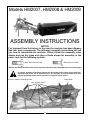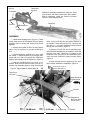
1
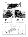
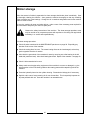
BUSH HOG
®
GEARDRIVE HAY MOWERS
Models
HM2007, HM2008, & HM2009
Operator’s Manual
ASSEMBLY ● OPERATION ● MAINTENANCE
1100
$4.00
Part No. 50030712
CONGRATULATIONS!
You have invested in the best implement of its type on the market today.
The care you give your Bush Hog implement will greatly determine your satisfaction
with its performance and its service life. We urge a careful study of this manual to provide
you with a thorough understanding of your new implement before operating, as well as
suggestions for operation and maintenance.
If your manual should become lost or destroyed, Bush Hog will be glad to provide you with
a new copy. Order from Bush Hog, P. O. Box 1039, Selma, Alabama 36702-1039.
As an authorized Bush Hog dealer, we stock genuine Bush Hog parts which are
manufactured with the same precision and skill as our original equipment. Our trained
service personnel are well informed on methods required to service Bush Hog equipment,
and are ready and able to help you.
Should you require additional information or assistance, please contact us.
YOUR AUTHORIZED
BUSH HOG DEALER
BECAUSE BUSH HOG MAINTAINS AN ONGOING
PROGRAM OF PRODUCT IMPROVEMENT, WE
RESERVE THE RIGHT TO MAKE IMPROVEMENTS IN
DESIGN OR CHANGES IN SPECIFICATIONS WITHOUT INCURRING ANY OBLIGATION TO INSTALL
THEM ON UNITS PREVIOUSLY SOLD.
BECAUSE OF THE POSSIBILITY THAT SOME
PHOTOGRAPHS IN THIS MANUAL WERE TAKEN OF
PROTOTYPE MODELS, PRODUCTION MODELS MAY
VARY IN SOME DETAIL. IN ADDITION, SOME
PHOTOGRAPHS MAY SHOW SHIELDS REMOVED
FOR PURPOSES OF CLARITY. NEVER OPERATE
THIS IMPLEMENT WITHOUT ALL SHIELDS IN PLACE.
HAY MOWER
TABLE OF CONTENTS
SECTION
SECTION
PAGE
PAGE
Stabilizer.........................................................25
Lifting Height ..................................................25
Transport - Unhitching ....................................27
Maintenance...................................................29
Lubrication......................................................31
Optional Equipment........................................35
Direction For Repair .......................................41
Problem/Fault Analysis & Corrections............44
Winter Storage ...............................................45
Conversion Chart & Lubricants ......................46
Assembly Instructions ....................................47
Safety Decals .................................................57
Warranty ...........................................................2
Dealer Preparation Check List .........................3
Safety Alert Symbols ........................................4
Safety Precautions ...........................................5
Federal Laws and Regulations.........................6
Machine Measurements ...................................7
Technical Data..................................................8
General Safety Instructions ............................11
Preparation For Use .......................................19
Mounting.........................................................21
PTO Shaft.......................................................23
Height Of The Suspension .............................25
RETAIL CUSTOMER’S RESPONSIBILITY
UNDER THE BUSH HOG WARRANTY
It is the Retail Customer and/or Operator’s responsibility to read the Operator’s Manual, to
operate, lubricate, maintain and store the product in accordance with all instructions and
safety procedures. Failure of the operator to read the Operator’s Manual is a misuse of this
equipment.
It is the Retail Customer and/or Operator’s responsibility to inspect the product and to have
any part(s) repaired or replaced when continued operation would cause damage or excessive wear to other parts or cause a safety hazard.
It is the Retail Customer’s responsibility to deliver the product to the authorized Bush Hog
Dealer, from whom he purchased it, for service or replacement of defective parts which are
covered by warranty. Repairs to be submitted for warranty consideration must be made within forty-five (45) days of failure.
It is the Retail Customer’s responsibility for any cost incurred by the Dealer for traveling to or
hauling of the product for the purpose of performing a warranty obligation or inspection.
1
BUSH HOG®
LIMITED WARRANTY
✯✯✯✯✯✯✯✯✯✯✯✯✯✯✯✯✯✯✯✯✯✯✯✯✯✯✯✯✯✯✯
Bush Hog warrants to the original purchaser of any new Bush Hog equipment, purchased from an
authorized Bush Hog dealer, that the equipment be free from defects in material and workmanship for a period
of one (1) year for non-commercial, state, and municipalities’ use and ninety (90) days for commercial use from
date of retail sale. The obligation of Bush Hog to the purchaser under this warranty is limited to the repair or
replacement of defective parts.
Replacement or repair parts installed in the equipment covered by this limited warranty are warranted
for ninety (90) days from the date of purchase of such part or to the expiration of the applicable new equipment warranty period, whichever occurs later. Warranted parts shall be provided at no cost to the user at an
authorized Bush Hog dealer during regular working hours. Bush Hog reserves the right to inspect any equipment or parts which are claimed to have been defective in material or workmanship.
DISCLAIMER OF IMPLIED WARRANTIES & CONSEQUENTIAL DAMAGES
Bush Hog’s obligation under this limited warranty, to the extent allowed by law, is in lieu of all warranties, implied or expressed, INCLUDING IMPLIED WARRANTIES OF MERCHANTABILITY AND FITNESS
FOR A PARTICULAR PURPOSE and any liability for incidental and consequential damages with respect to
the sale or use of the items warranted. Such incidental and consequential damages shall include but not be
limited to: transportation charges other than normal freight charges; cost of installation other than cost
approved by Bush Hog; duty; taxes; charges for normal service or adjustment; loss of crops or any other loss of
income; rental of substitute equipment, expenses due to loss, damage, detention or delay in the delivery of
equipment or parts resulting from acts beyond the control of Bush Hog.
THIS LIMITED WARRANTY SHALL NOT APPLY:
1. To vendor items which carry their own warranties, such as engines, tires, and tubes.
2. If the unit has been subjected to misapplication, abuse, misuse, negligence, fire or other accident.
3. If parts not made or supplied by Bush Hog have been used in connection with the unit, if, in the sole judgement of Bush Hog such use affects its performance, stability or reliability.
4. If the unit has been altered or repaired outside of an authorized Bush Hog dealership in a manner
which, in the sole judgement of Bush Hog, affects its performance, stability or reliability.
5. To normal maintenance service and normal replacement items such as gearbox lubricant, hydraulic fluid,
worn blades, or to normal deterioration of such things as belts and exterior finish due to use or
exposure.
6. To expendable or wear items such as teeth, chains, sprockets, belts, springs and any other items that in the
company’s sole judgement is a wear item.
NO EMPLOYEE OR REPRESENTATIVE OF BUSH HOG IS AUTHORIZED TO CHANGE THIS LIMITED WARRANTY IN ANY WAY OR GRANT ANY OTHER WARRANTY UNLESS SUCH CHANGE IS MADE
IN WRITING AND SIGNED BY BUSH HOG’S SERVICE MANAGER, POST OFFICE BOX 1039, SELMA,
ALABAMA 36702-1039.
✯✯✯✯✯✯✯✯✯✯✯✯✯✯✯✯✯✯✯✯✯✯✯✯✯✯✯✯✯✯✯
Record the model number, serial number and date
purchased. This information will be helpful to your
dealer if parts or service are required.
MODEL NUMBER
MAKE CERTAIN THE WARRANTY REGISTRATION
CARD HAS BEEN FILED WITH BUSH HOG/
SELMA, ALABAMA
SERIAL NUMBER
DATE OF RETAIL SALE
2
DEALER PREPARATION CHECK LIST
HAY MOWER
BEFORE DELIVERING MACHINE — The following check list should be completed.
Use the Operator’s Manual as a guide.
❒
❒
❒
❒
❒
❒
❒
❒
1.
Assembly completed.
2.
Gearbox filled with oil.
3.
All fittings lubricated.
4.
All shields in place and in good condition.
5.
All fasteners torqued to specifications given in Torque Chart.
6.
All decals in place and readable. (See decal page.)
7.
Overall condition good (i.e. paint, welds)
8.
Operators manual has been delivered to owner and he has been instructed
on the safe and proper use of the mower.
Dealer’s Signature
Purchaser’s Signature
THIS CHECKLIST TO REMAIN IN OWNER’S MANUAL
It is the responsibility of the dealer to complete the procedures listed
above before delivery of this implement to the customer.
3
Safety Alert Symbol
This Safety Alert Symbol means: “ATTENTION! BECOME ALERT!
YOUR SAFETY IS INVOLVED!”
This symbol is used to call attention to safety
precautions that should be followed by the
operator to avoid accidents. When you see this
symbol, carefully read the message that follows
and heed its advice. Failure to comply with safety precautions could result in death or serious
bodily injury.
Safety Signs
Signal Words
The signal words DANGER, WARNING, AND CAUTION are used on the equipment safety signs. These words
are intended to alert the viewer to the existence and the degree of hazard seriousness.
This signal word indicates a potentially hazardous situation
which, if not avoided, will result in death or serious injury.
White letters on RED
This signal word indicates a potentially hazardous situation
which, if not avoided, could result in death or serious injury
It may also be used to alert against unsafe practices.
Black letters on ORANGE
This signal word indicates a potentially hazardous situation exist
which, if not avoided, may result in minor or moderate injury.
It may also be used to alert against unsafe practices.
Black letters on YELLOW
4
IMPORTANT SAFETY PRECAUTIONS
This symbol is used to call attention to safety precautions that should be followed by
the operator to avoid accidents. When you
see this symbol, carefully read the message
that follows and heed its advice. Failure to
comply with safety precautions could result
in serious bodily injury.
In addition to the design and configuration of equipment, hazard control and accident prevention are dependent upon the awareness, concern, prudence and proper training of personnel in the operation, transport,
maintenance and storage of equipment. Lack of attention to safety can result in accident, personal injury,
reduction of efficiency and worst of all—loss of life. Watch for safety hazards and correct deficiencies promptly. Use the following safety precautions as a general guide to safe operations when using this machine.
Additional safety precautions are used throughout this manual for specific operating and maintenance procedures. Read this manual and review the safety precautions often until you know the limitations.
1.
Read the Operator’s Manual. Failure to read the Operator’s Manual is considered a misuse of this equipment.
2.
Become familiar with all the machine’s controls and all the caution, warning and danger decals affixed
to the machine before attempting to start or operate.
3.
Before starting or operating the machine, make a walk around inspection and check for obvious defects
such as loose mounting bolts and damaged components. Correct any deficiency before starting.
4.
Do not allow children to operate the mower. Do not allow adults to operate it without proper instruction.
5.
Do not carry passengers.
6.
Keep the area of operation clear of all persons, particularly small children and pets. The operator should
cease mowing whenever anyone comes within the operating area.
7.
Clear the work area of objects which might be picked up and thrown.
8.
Use a piece of cardboard or wood rather than hands to search for hydraulic leaks. Escaping hydraulic oil
under pressure can penetrate skin. If fluid is injected into the skin, it must be surgically removed within a
few hours by a doctor familiar with this form of injury or gangrene may result.
9.
Do not operate without all guards and shields in place and in good condition.
10. Stop PTO, lower implement to ground, place tractor transmission in neutral or park, set parking brake, stop
tractor engine, remove ignition key and wait for all motion to completely stop before leaving the tractor.
11. Keep hands and feet away from blades.
12. This mower is not to be operated in any area where people may be present unless all
sides of the unit are enclosed by a curtain guard that is in good repair.
13. Wear personal protective equipment such as, but not limited to, protection for eyes, ears, feet, hands and
head when operating or repairing the equipment. Do not wear loose clothing or jewelry that may catch on
equipment moving parts.
14. When performing adjustments or maintenance on the mower, first lower it to the ground or block it securely
at a workable height.
15. Never stand between tractor and mower while tractor is being backed to the cutter hitch.
16. Reduce speed when transporting mower to avoid bouncing and momentary loss of steering.
17. Use tractor flashing warning lights, day or night, when transporting mower on road or highways unless prohibited by law.
18. Pin transport lock to retain cutter bar in transport position.
19. Lower mower to ground before unhitching from tractor.
20. In the event that someone other than yourself will operate this equipment we firmly suggest that all
SAFETY references be discussed prior to operation.
21. It is recommended that tractor be equipped with Rollover Protective System (ROPS) enclosed cab, and a
seat belt.
5
IMPORTANT FEDERAL LAWS AND REGULATIONS* CONCERNING
EMPLOYERS, EMPLOYEES AND OPERATIONS.
*(This section is intended to explain in broad terms the concept and effect of the following federal laws and
regulations. It is not intended as a legal interpretation of the laws and should not be considered as such).
U.S. Public Law 91-596 (The Williams-Steiger Occupational and Health Act of 1970) OSHA
This Act Seeks:
“...to assure so far as possible every working man and woman in the nation safe and healthful working
conditions and to preserve our human resources...”
DUTIES
Sec. 5 (a) Each employer—
(1) shall furnish to each of his employees employment and a place of employment
which are free from recognized hazards that are causing or are likely to cause
death or serious physical harm to his employees;
(2) shall comply with occupational safety and health standards promulgated under
this Act.
(b) Each employee shall comply with occupational safety and health standards
and all rules, regulations and orders issued pursuant to this Act which are
applicable to his own actions and conduct.
OSHA Regulations
Current OSHA regulations state in part: “At the time of initial assignment and at least annually thereafter, the
employer shall instruct every employee in the safe operation and servicing of all equipment with which the
employee is, or will be involved.” These will include (but are not limited to) instructions to:
Keep all guards in place when the machine is in operation;
Permit no riders on equipment;
Stop engine, disconnect the power source, and wait for all machine movement to stop before
servicing, adjusting, cleaning or unclogging the equipment, except where the machine must be
running to be properly serviced or maintained, in which case the employer shall instruct employees
as to all steps and procedures which are necessary to safely service or maintain the equipment.
Make sure everyone is clear of machinery before starting the engine, engaging power, or operating
the machine.
EMPLOYEE TRACTOR OPERATING INSTRUCTIONS:
1. Securely fasten your seat belt if the tractor has a
ROPS.
5. Watch where you are going, especially at row
ends, on roads, and around trees.
2. Where possible, avoid operating the tractor near
ditches, embankments, and holes.
6. Do not permit others to ride.
7. Operate the tractor smoothly - no jerky turns,
starts, or stops.
3. Reduce speed when turning, crossing slopes, and
on rough, slick, or muddy surfaces.
8. Hitch only to the drawbar and hitch points recommended by tractor manufacturers.
4. Stay off slopes too steep for safe operation.
9. When tractor is stopped, set brakes securely and
use park lock if available.
Child Labor Under 16 Years Old
Some regulations specify that no one under the age of 16 may operate power machinery. It is your
responsibility to know what these regulations are in your own area or situation. (Refer to U.S. Dept. of
Labor, Employment Standard Administration, Wage & Home Division, Child Labor Bulletin #102.)
6
Models HM2007 - HM2008 - HM2009
600 mm (24”)
1050 mm (42”)
Model HM2007 - 3680 mm (145”)
Model HM2008 - 4060 mm (160”)
Model HM2009 - 4440 mm (175”)
Transport 1170 mm (46”)
1040 mm (41”)
Model HM2007 - 1900 mm (75”)
Model HM2008 - 2280 mm (90”)
Model HM2009 - 2660 mm (105”)
160 mm (6-1/4”)
(All measurements are approximate and stated in mm and inches)
7
1110 mm (44”)
860 mm (34”)
555 mm
(22”)
1095 mm (43”)
Technical Data (Conversion table
- see page 46 ).
Model HM2007
Model HM2008
Model HM2009
Weight . . . . . . . . . . . . . . . . . . . . . . . . . . . kg (lb.)
415 (915)
440 (970)
465 (1025)
P.T.O. (Input speed) . . . . . . . . . . . . . . . . . . rpm
540
540
540
Power requirement, min. . . . . . . . . . . . kW (HP)
30 (40)
33 (45)
37 (50)
P.T.O. shaft with overrun clutch . . . . . . . . . . . . .
Standard
Standard
Standard
Number of discs . . . . . . . . . . . . . . . . . . . . . . pcs.
5
6
7
Number of knives . . . . . . . . . . . . . . . . . . . . . pcs.
10
12
14
Speed of discs . . . . . . . . . . . . . . . . . . . . . . . rpm
3000
3000
3000
Capacity: Drive speed . . . . . . . . . . . km/h (mph)
6 - 25 (4-15)
6 - 25 (4-15)
6 - 25 (4-15)
Cutting width . . . . . . . . . . . . . . . . . . . . . mm (in.)
2000 (79)
2400 (95)
2800 (110)
Stubble height . . . . . . . . . . . . . . . . . . . . mm (in.)
35 - 60
(1-3/8 - 2-3/8)
35 - 60
(1-3/8 - 2-3/8)
35 - 60
(1-3/8 - 2-3/8)
High cut skids (extra equipment ) . . mm (in.)
65 - 110
(2-1/2 - 4-3/8)
65 - 110
(2-1/2 - 4-3/8)
65 - 110
2-1/2 - 4-3/8)
Generally about supplementary equipment:
Machines are from the factory available with several options. See your Bush Hog dealer for more information
on these options. This supplementary equipment and other extra equipment are mentioned on page 35.
Fitting to the tractor
The tractor must be of a suitable size, adhere to the local laws. Please note that side-mounted
machines affect the stability of the tractor when driving in hilly conditions.
Couple the machine to the three-point suspension of the tractor. The tractor must have stabilizing chains on
the lifting arms of the three-point suspension.
IMPORTANT
To achieve a good ground clearance under the machine when it is lifted in the three-point-suspension of the
tractor the lifting arms must be able to be raised at least 950 mm (37-1/2”) above the ground. Otherwise, the
stated ground clearances, shown on page 25 , will be smaller. This especially applies to the wide machines
model HM2008 and HM2009.
We reserve the right to make alterations without notice. We also make reservations as to the possible misprints in the manual.
8
Machine Identification
The machine serial number and manufacturer information can be found on the metal
plate, as shown.
9
kg / lb.
6
10
Safety
①
Any operator, repairer and owner must be familiar with the warning instructions for the machine
in this manual, before operations commence.
Always work carefully with agricultural machinery. Read through and observe the safety instructions
in this manual. Safety is your responsibility.
Pay particular attention to this symbol. It means that there could be a serious
hazard. It emphasizes precautions which have to be complied with in order to
prevent accidents.
This symbol can be found throughout this manual and on the warning signs on
the machine. They are for your safety and should be observed at all times.
General Safety Instructions
②
Be careful when other people or animals are close by! Never start up the machine when people
or animals are close or on the machine or tractor. Never stand between the tractor wheels and
the machine.
Adhere to the local laws regarding children’s minimum working age with agricultural machinery.
③
Use of the machine. The machine must only be used for harvest of common grass and grain
crops. The machine must not be used for harvest of maize, lawn mowing in parks and cutting
of hedges, neither in vertical or in horizontal position.
④
Use personal protection devices. Do not wear loose clothing which may catch in any of the
moving parts. In dusty conditions a suitable mask must be used.
Take care of excessive sound level. Certain tractor/implement combinations, dependent on
operating conditions, may generate a noise level in excess of 85 dB at the operators ear, even
in a quiet cab. In these circumstances ear protection must be worn. Keep cab windows and
doors CLOSED at all times to reduce noise level.
⑤
The machine must only be coupled to a correctly sized tractor, and no other machines or
implements must be coupled. The weight of the tractor must correspond to the machine.
Observe all local laws. Be careful that the tractor is not unbalanced when coupling.
Make sure that the tractor has the correct PTO. A machine intended for 540 rpm PTO input
speed must never be coupled to a tractor with 1000 rpm PTO output speed.
⑥
Coupling of tractor and machine must be carried out as explained in the instructions. All lock
pins must have locking retainers. Observe all local laws regarding road transport.
⑦
Work in a safe way. The tractor engine must ALWAYS be stopped and the ignition key
removed before carrying out repairs, cleaning, lubricating or maintaining the machine.
11
12
①
Safety guards. Make sure that ALL GUARDS are in good order and fitted correctly. Do no
attempt to start the machine before ensuring this.
Pay particular attention to the plastic guards of the PTO shaft. If damaged they must be
replaced. The chain locks of the guards MUST always be fitted on a suitable place on the tractor
and the machine to prevent the outer plastic guards turning.
②
Hydraulics. Be very careful when dealing with hydraulics. Use eye protection and gloves.
Escaping hydraulic oil under pressure might penetrate into the skin and cause serious infection.
See a doctor if you have been exposed to injury.
Be watchful - damaged hydraulic hoses must be replaced immediately. Never use sealing tape or
similar to repair the hoses. The hoses must be securely fixed. All hydraulic hoses of the
machine should be replaced at least every 4 years.
③
Remember when uncoupling, and when leaving tractor/machine. The machine must be in the
working position when uncoupling from the tractor. All hydraulic functions must be in neutral position, the machine must be lowered to the ground and be safely secured. Never allow children to
play or be near agricultural machinery.
④
Drive safely. Be aware of your responsibility - carelessness or slovenliness can cause serious
injury or death.
Before transporting on public roads, - always check that the machine is locked with cotter bolt and
stop valve, that the coupling is in order, and that possible hydraulic systems and pawls are locked,
see the manual of the machine.
Drive carefully. Reduce speed when turning and driving on uneven ground - take care that tractor/machine is not swinging and becoming unstable.
Please note that there is danger of overturning when working on slopes and in soft ground conditions.
The machine must not be used in situations that unbalances the tractor.
⑤
Lighting. It is the responsibility of the owner/operator to provide correct lights and reflectors on
the machine, when it is being transported on public roads after dark. Observe the local laws.
⑥
Safety equipment. Always carry first aid equipment on the tractor. Also observe local laws concerning fire extinguishers. When working with hay or straw a fire extinguisher must be available at
all times.
⑦
Spare parts. For safety reasons use only original spare parts. If injury occurs when using nonoriginal spare parts the Bush Hog warranty is invalidated.
⑧
Maintenance. Take care that the machine is properly maintained and kept in good safe working
condition. Never change the technical construction of the machine.
13
C
A
Model
Kg ( lb.)
HM2007 415 (915)
HM2008 440 (970)
HM2009 465 (1025)
B
D
14
Safety instructions during crane lift
Only use approved crane material. The machine must be in working position.
Weight is stated on the drawing. Make sure that crane straps are securely
fastened before lifting. Use a guide rope (not shown) to keep the machine in
position.
Be careful - make sure that nobody stand under or near the machine when it is
being lifted.
Fasten chain (A) on the machine as shown. Lift the machine in crane bracket (B). Use support
rope, minimum 6 mm (1/4”) nylon rope at (C) and (D).
15
16
New Machine - be careful
①
Read the directions for use. Great care must be taken, when starting up a new machine. Incorrect
mounting, wrong operations, etc., can result in expensive repairs and loss of profits. Bush Hog’s
factory warranty is voided if the instructions of this manual are not adhered to.
NOTICE
Be especially attentive to the following when starting a new machine.
②
Check that the machine is mounted correctly, and that it is not damaged. Machines with hydraulic
stabilizer: Be certain that the hydraulic hoses are mounted so that they are long enough to allow
for cylinder movements.
③
Be very careful when the machine is coupled to the tractor. If the coupling has not been carried
out as explained in this manual the machine will not work correctly. Please note that the working
height (A) is adjusted correctly. See page 24.
④
Be very careful when fitting the PTO shaft. If the PTO shaft is too short or too long it can cause
great damage to the machine and tractor. Overriding clutch must be fitted on the shaft end of the
machine. See pages 22 & 23.
If the PTO shafts of the machine are noisy or vibrating the fitting instructions must be repeated.
See pages 22 & 23.
⑤
It is very important to check the area of motion of the stabilizer. If the adjustment has not been
carried out as explained in this manual the machine will not work correctly. See page 24.
⑥
Before starting up a new machine it must be lubricated. Check that gearbox and cutterbar are
filled with oil and that the oil level is correct. Use only the oil grades prescribed in the manual.
⑦
Check that all bolts at cutting discs and knives are tightened before the machine is started.
Check and re-tighten all bolts on the machine after the first hour of operation. This is especially important for quickly rotating parts. Also re-tighten after service work has been
carried out.
17
215 mm (8-1/2”)
HM2007, HM2008
290 mm (11-1/2”)
HM2009
18
HM2009
HM2008
HM2007
Preparation For Use
①
The photo shows a fully assembled machine. For shipping,the machine has been partly dismantled - reassembling is carried out according to the assembly instructions later in this manual.
Do the following before coupling the machine to the tractor:
(A) Check that the stabilizer is equipped with the correct spring. The color of the spring must be
as shown.
Model
HM2007
HM2008
HM2009
Color
Green
Green
Black
(B) Check that the machine is equipped with the correct connecting link, and that the stabilizer is
fitted in the correct hole.
NOTICE
If the above are not connected correctly the machine will not be able to work properly.
(C) Lubricate the sliding surface of the lifting bracket with lithium grease or equivalent.
(D) Lubricate the carrying tube of the swing bar with lithium grease or equivalent. The lubrication
is easier to carry out by first removing the front support leg from the right hand hitch lug.
The three point lift hitch may then be moved slightly forward and swung
down and forward. After this the hitch can be turned to the left, so that the carrying
tube can be lubricated at full length.
19
D
B
1
A
3
C
Clip Pin
Pawl
2
E
G
F
Remove Clip Pin and Rotate Pawl
20
Mounting - coupling
The coupling between machine and tractor must be carried out as explained in the
instructions. If the machine becomes disconnected from the tractor it could cause
severe damage or death.
Fitting of the suspension
①
Check that the lift arms of the tractor are adjusted to the same height from the ground. Turn the
drawbar (A) to the side or remove it. Also check the tire pressure - it is important that the right
hand wheel (B) is inflated to the prescribed pressure.
If the width of the tractor is less than 2200 mm (86.6”), measured from the outer edge of the tires,
hitch pins (E) must be used. Where the tractor is wider than 2200 mm (86.6”), pins (F) must be used.
NOTE: Model HM2007 is equipped with Cat. II pins to the outside and Cat. I pins to the inside. If used
with a Cat. II tractor, a Cat. II bushing must be used on the Cat. I inside pin.
②
Back the tractor to the machine - fit the lift arms (C) (right hand/left hand) and the top link (D).
Raise the machine with the lift arms (C) so that it is clear of the ground and raise both of the support legs.
Tighten the stabilizer links of the tractor. Check that the arms have the same length on the right
hand and left hand sides.
③
Turn the lock pawl (G) of the stabilizer in the direction indicated by arrow.
NOTE: The lock pawl can only be operated when the machine is coupled to the tractor, and
the machine must be raised clear of the ground with the three-point linkage of the tractor.
21
1
A
Shortest Cutting Height
C
3
D
4
40
(1-1 mm
/2”)
b
c
a
min. 150 mm (6”)
d
22
①-②
Lower the machine to the ground. Adjust the top link (A) to the minimum cutting height as shown
at (B).
PTO shaft
③-④
Only use a tractor PTO shaft set for 540 rpm operation. It is dangerous to couple a tractor with 1000 rpm PTO output to a machine intended for 540 rpm PTO
input speed.
IMPORTANT
PTO ADAPTERS SHOULD NOT BE USED WITH ANY BUSH HOG
EQUIPMENT. FAILURE TO FOLLOW THESE INSTRUCTIONS WILL
CAUSE DRIVELINE FAILURE AND POSSIBLE TRACTOR DAMAGE.
When fitting the first time, before checking the shaft length, the top link must be adjusted to minimum cutting height (short top link). Follow this procedure:
⑤
•
Adjust the linkage so that the PTO stub shafts are level.
•
Fit the two parts of the PTO shaft onto the shafts of the tractor and the machine respectively.
The clutch is placed at the machine end (C).
•
Place the two shaft halves together as shown at (D) and mark the shortening length (about 40 mm
(1-1/2”) clearance).
NOTE: Some tractor types do not require a shortening of the shaft.
Shortening of the shaft
⑥
When shortening the PTO shaft the four parts a - b - c - d must be shortened equally. After shortening, the tube ends and the shaft ends have to be filed off, cleaned of filings and lubricated.
Checking of PTO shaft length
NOTICE
Fit the shortened shaft. Carefully check that the shaft does not bottom when the linkage is raised
or lowered. Also check that the sliding tubes overlap with at least 150 mm (6”), when the machine
is in the working position.
This check should always be carried out when the machine is coupled to the tractor. If the tractor
is replaced the above check must be carried out and if necessary a new adaptation of the shaft
must be done.
23
450 - 480 mm (Model HM2009 - max. 450 mm/18”)
(18” - 19”)
min. 950 mm (38”)
*
Model HM2007 - 13mm (1/2”)
Model HM2008 - 11mm (7/16”)
Model HM2009 - 8 mm (5/16”)
24
①
Height of the suspension
Important
The working height of the suspension 450 - 480 mm (18 - 19”) is maintained with the chain (A).
The chain is locked as shown at (B).
NOTE: If the machine is equipped with high cut skids the working height of the linkage must be
500 - 530 mm (20 - 21”). If these settings are not adhered to, it could result in excessive
wear to the skids and gearbox bushings, and cause abnormal wear on the breakaway
assembly.
②
Stabilizer
Check the movement area (C) of the stabilizer when the machine is in the field and lowered to the
working position. If necessary adjust the right hand lift arm of the tractor (D):
If the distance (C) is too big, raise the lift arm at (D)
and oppositely if the distance is to small. NOTE: Adjustment of the lift arm is easier to carry out
when the machine does not load it - therefore raise the machine, engage pawl, shown at the bottom of page 26, remove suspension chain and lower the machine to the ground.
* Applies especially for model HM2009
To assure an optimum ground following ability, it is recommended to work with a distance of 8 mm
(5/16”) at (C) on even land. When working on uneven land, it is recommended to use a bigger distance than 8 mm (5/16”), but note that the lifting height of the machine will then be reduced when
turning in the field. Read more about lifting height in the following paragraph.
Check that the distance from the suspension to the ground does not exceed 450 mm (18”). See Fig. 1.
③
Lifting height
The lifting height of the tractor must be at least 950 mm (37-1/2”) as shown. This lifting height corresponds to a ground clearance of approx. 300 mm (12”) at (E) and 420 - 520 mm (16-1/2 - 21”) at
(F) depending on machine type and tractor size.
If the ground clearance is too small, check the adjustment of the stabilizer. Also check tire pressure in the right hand rear wheel of the tractor.
Lifting bracket (G) from the factory is fitted in the shown standard position. If the bracket is fitted in
the holes (H) the ground clearance will be larger at (E) but smaller at (F).
NOTICE
Make sure that moveable parts are lubricated as shown on page 18. If not lubricated, lifting function will not work satisfactorily.
25
2
1 Transport Position
E
B
4
C
6 Un-Hitched
Support Legs
D
A
5
E
7
26
G Lock Pawl Engaged
F Chain
Transport - Unhitching
①-②
Transport
As shown the machine can be raised to the vertical position. Raise the machine clear of the
ground with the lift arms (A) of the tractor, then raise the machine to the vertical position with the
hydraulic cylinder of the machine.
Be careful, check that the curtain frame of the machine can clear the rear wheel of the tractor at
(B): If necessary the curtain frame can be turned forward by disengaging the pawl (C).
Be careful. Make sure that no persons are near the machine when it is being raised
or lowered during transport. Lock the machine with “L” pin (D) and retaining valve (E).
The “L” pin is placed in the hole on the left hand side, when the machine is lowered to
working position.
Great care must be taken during transport on public roads. Reduce speed when turning and driving on uneven roads. Observe local laws for road transport.
It is the responsibility of the owner/operator to provide correct lights and reflectors on
the machine, when it is transported on public roads after dark.
Unhitching
③
④-➆
WARNING
The machine must never be unhitched from the tractor in the transport position.
The machine will be unstable and could overturn. Always store the machine in
the working position with the cutter bar on the ground.
Raise the machine with the lift arms of the tractor, remove the chain (F) and lower both of the support legs. Engage the lock pawl (G), lower the machine to the ground and unhitch the tractor.
27
1 A
2 B
3 C
95 ± 5
80 ± 5
60 ft./lbs.
70 ft./lbs.
H
F
D
G
E
28
Maintenance
During all service operations concerning knives and cutting discs the tractor engine
must be stopped and the hand brake activated. If the machine is in the raised position it must be firmly supported. Also refer to page 5, item 10.
Re-tighten the bolts of the cutting discs and knives on your new machine
before starting and again after about 1 hour of operation. The same applies
when any service work is done, for example, replacing knives.
①-④
Knives - cutting discs
The curtain (A) of the machine can be rotated so that there is free access for inspection of cutting
discs and knives. Also refer to page 26, Figure 4 - C.
NOTICE
Check daily that the bolts of the cutting discs and knives are tightened, and that cutting
discs, cones and knives are undamaged. If the rotating parts are unbalanced, vibrations
could occur causing damage to the cutterbar. Damage of this kind voids the warranty.
NOTICE
Keep the cones (B) and (C) on the right hand and left hand sides clean. If the cones are unbalanced, vibrations could occur causing damage to the cutterbar.
Damaged knives (D) must be replaced immediately. Twisted knives (Standard) may be turned over
and used in the same location. If flat knives (Optional) are worn on one side only, they can be
interchanged by using the knives from another cutting disc that rotates in the opposite direction.
This will allow blades to be used on both sides. Check that bolts (E) and nuts (F) are in good order
- if not, they must be replaced.
NOTE: The knives have to be in the position shown (G) to remove the bolts.
Only use original replacement parts. The cutting discs of the machine rotate at 3000
rpm - never compromise with safety.
Operate with safety - note the following:
● The cutting discs are to be fitted in pairs as shown (90° displacement of knives).
● Always use LOCTITE 242 on the bolts of the cutting discs (H).
● Torque setting as stated - make sure that splines and holders are kept clean.
● Special for model HM2007 and model HM2009 with optional flat blade kit: The cutting disc
next to the gearbox is different from the others - See page 51 for illustration.
29
1
D
2
30
E Hole In Front Belt Guard
①-②
V-belts
The spring is to be tightened so that the end of the spring is in alignment with the edge of the
bracket, as shown.
Models HM2007 - HM2008 - HM2009 (D) = 0 mm
New V-belts should be re-tightened after a few hours operation. Inspection of V-belts is carried out
through hole (E). The front part of the belt guard can easily be removed.
Lubrication (Lubricants, - see page 46)
Before starting to use a new machine: Check the oil level of the gearbox and the cutterbar and
lubricate the machine and driveline. See pages 32 & 33 and observe all lubrication decals.
③
Ev
er
y1
0t
h
Ev
ho
er
ur
y4
(d
0
ail
th
Nu
y)
ho
m
ur
be
ro
fn
ipp
les
Lubrication generally
*
(A)
●
(B)
●●
(C)
●●
●
5
Driveline with overrun clutch
2
Swivel link (twice daily)
All movable parts should be lubricated with oil or grease once-twice/daily be especially attentive to the sliding surfaces shown.
*
All universal crosses and bearings in the plastic tubes of the PTO shaft are to be lubricated every 8
- 10 hours of operation. Profile tubes should be separated, cleaned and lubricated after 40 hours
use. Use lithium grease.
NOTICE
Regularly check the driveline. Any damage or lack of lubrication to the hollow shaft may cause the
PTO shaft on the tractor or machine to be damaged beyond repair.
During still periods (one week or more): Wash and lubricate the machine, spray it with a thin
layer of rust protecting oil - especially important at cutting discs.
The hydraulic lifting cylinder of the machine: During prolonged storage press the piston rod
into the piston housing (remove the complete lifting cylinder at the connection link on the gearbox),
or coat the exposed surface of piston rod with grease.
31
A
2
Oil Filler Plug
4
5
D
32
max. 9 mm (11/32”)
3
min. 6 mm (1/4”)
1
B
C
①-④
Oil - cutterbar
The following operations must be carried out in a safe and secure way. During all
work near the cutting discs of the machine the tractor engine must be stopped and the
PTO shaft disconnected.
Check the oil level daily in the following way:
● Place the machine on level ground - check the position of the cutterbar with a level as
shown at (A). The bar must be level in this direction. Check also that the cutterbar is level in
the driving direction, shown at (B).
● Remove the oil filler plug. It is situated between the second and third disc on the left hand side
of the machine. Wait for 3 minutes (if the oil is cold: wait for 15 minutes) and check the oil level
using a steel tape measure as shown in (C). Amount of oil from minimum to maximum is about
1 litre (33.8 ozs.) which equals 3 mm (.11”) difference in depth.
Amount of oil:
Model HM2007 = 3.5 litres (3.7 qts.) and for following oil change approx. 3.1 litres (3.3 qts.).
Model HM2008 = 4.0 litres (4.2 qts.) and for following oil change approx. 3.6 litres (3.8 qts.).
Model HM2009 = 4.5 litres (4.8 qts.) and for following oil change approx. 4.1 litres (4.3 qts.).
Change of oil: First time after about 10 hours operation and thereafter every 200 hours of operation or at least once a year. The drain plug for oil is situated on the left hand side
of the cutterbar.
NOTICE
The amount of oil must never exceed the maximum stated. Otherwise the oil will be overheated
and may damage the bearings in the cutterbar.
⑤
Oil - bevel gearbox
Check the oil level of the gearbox daily. The gearbox must be level.
Oil level
: Plug (D).
Amount of oil: 0.3 litres (10 ozs.).
Change of oil : Change the oil after about 10 hours of operation and thereafter at least once a
season. The oil can be drained through level plug when the cutterbar is in vertical
position.
NOTICE
This transmission rotates at high speed - about 3000 rpm. Therefore, it is important to use
the correct type and amount of oil. Otherwise overheating will occur and damage the transmission. Damage of this kind is excluded from Bush Hog warranty.
At the back of this manual, page 46 “lubricants” are shown. Only use oil types marked (H) for
transmission with such high working speeds.
33
1
2
Swath Roller
Swath Board
34
Optional equipment
①
Right-hand & Left-hand swath rollers
The machine can be equipped with swath rollers as shown.
②
Right-hand & Left-hand swath boards
The machine can be equipped with swath boards as shown.
35
2
1 Hillside Kit As Seen From Below
A
m
m ”)
5 8
22 -7/
(8
2-3 mm
(5/16 - 1/8”)
4 Outside High Skid
3 Inside High Skid
B
C
36
①-②
Optional hillside kit
The spring lock keeps the machine in position in proportion to the tractor. If the machine meets a
firm obstacle, the lock is released and the machine swings to the rear. Refer to the Hillside Kit
Instructions for more information.
The spring lock must be adjusted. Screw (A) is eccentric. Tighten the bolt to minimum 225 mm (8-7/8”)
Refer to Hillside Kit Instructions..
③-④
Optional high skid
The skids of the machine are fixed and cannot be height-adjusted. If the machine operates in
fields with many stones, molehills, etc., high skids (B) and (C) are recommended. The cutting
height is then increased to about 60 mm (2 -3/8”). Also refer to NOTE on page 25 for height adjustment.
Fitting: Set of skids, 2 pcs., are to be placed in the right hand and left hand side of the machine.
They must be fitted below the fixed skids as shown in photos 3 and 4.
37
1
3
2
Flat Blades
Left Cone
38
Throwing Wings
①
Special flat knives
Special flat knives are recommended for rocky conditions.
Special flat knives may be used on all models. However, for Models HM 2007 and HM2009, the
number one cutting disc, next to the gearbox, must also be changed. The special flat knives and
number one disc are available from your dealer.
②
Throwing wings
Throwing wings are recommended for very light grass conditions.
③
Left cone
The cone (B) at gearbox is standard equipment for model HM2008 and model HM2009. It is available for model HM2007 as extra equipment. The cone is recommended for mowing of long, wilted
grass.
39
2
A
B
1.4 - 2.8 mm
(.055 - .110”)
E
500 mm
(19-5/8”)
1
F
0 - .05mm
(0 - .002”)
G
H
40
Directions for repair
Repair must only be carried out by competent persons with experience of using workshop equipment and trained in the repair of agricultural machinery in a safe and
responsible manner.
①-②
Stabilizer
Be careful. Remove stabilizer from machine for disassembly. Never disassemble the
stabilizer (A) without use of special tools (B). The spring is tightened to 800 - 1000 kg
(1764 - 2205 lbs.). Special tools (B) are available.
③
Hydraulic lifting cylinder
New set of seals must be fitted as shown. Sealing rings (C) and (D) must be positioned as shown.
④
Bevel gearbox
NOTICE
Repair of the gearbox must only be carried out by competent persons with thorough knowledge of
such work. Tooth clearance must be within the stated values.
NOTE THE FOLLOWING:
Checking of tooth clearance (mesh) can only be measured on a clean and oil free gearwheel.
Refer to gearbox repair manual for all gearbox repairs.
Use a 500 mm (19-5/8”) long torque bar attached to the pinion shaft bolt when checking the tooth
clearance. The stated values from 1.4 to 2.8 mm are valid with a 500 mm torque bar. Adjust tooth
clearance with shims at (E). Adjust the slack of the roller bearing at the bevel pinion wheel by
means of the washers (G) and (H).
Sealing ring (F) must be turned as shown.
Important, when fitting the gear to the machine:
Use tab to lock the 8 bolts retaining the gear to the cutterbar.
41
42
①-➃
Cutterbar
NOTICE
Be particularly attentive when checking or repairing the cutterbar - it rotates at 3000 rpm. Take
care that worn bearings and gear wheels must be replaced in time. Otherwise a single damaged
bearing might cause damage to the whole cutterbar. Use LOCTITE when stated - hardening time
approx. 15 minutes.
Intermediate gear (illustration 1)
Inspection of intermediate gear can be carried out through the collar bearings holes.
Intermediate gears can only be removed through the opening in the right hand side of the cutterbar, but gear at (L) and gear at (T) (only model HM2007 and model HM2009) can be removed
through collar bearing hole. These gears are smaller than the others. Note the following when
replacing the bearings:
● When pressing out the bearing, sealing ring (A) is pressed into pieces. Use a new sealing ring
when fitting a new bearing.
● Check that gasket (B) and (D) have not been damaged. The thread surfaces on bolt (C) must
be locked with LOCKTITE type 242. The torque setting is Nm = 90 (66.4 ft./lbs.).
Collar bearings (illustration 2)
Press the bearing into the bearing housing. Mount the locking (E). Fill the hollow space (F) of the
flange, shown at (F), with grease of good quality. NOTE: A tool kit is available for this procedure.
Use a support on the inner race of the bearing when the flange axle is pressed into the bearing.
Place the key (G) in the gear wheel hub, carefully press the parts together, and be sure that the
key slides correctly into the keyway of the shaft.
Apply a little LOCTITE 242 to the retaining bolt (H) and tighten with a torque wrench to Nm =50 (37
Ft. Lbs.).
Fixing of collar bearing (ilustration 3)
Lock the bolts (J) by means of tabs (I). Torque moment is 90± 3 Nm (66 ± 2 Ft. Lbs ). Check that
the gaskets (K) in the loose threaded pins are not damaged. Use the threaded rod (R) for the collar
bearing in the righthand side.
Synchronizing (illustration 4)
Before fitting the collar bearing take care that the collar bearing flanges are in the correct positions
in relation to each other. This is especially important between the 1st and 2nd disc on the model
HM2007 and model HM2009, as the discs rotate the same way. This synchronizing can be
achieved in the following way:
● Fit the 1st collar bearing - turn the flange so that the marked edge (M) faces to the rear.
● Fit the 2nd collar bearing. Turn the flange so that the marked edge (N) faces forward in the
drive direction before lowering the gear wheel into mesh. Continue with this procedure when
fitting the other collar bearings (P), (Q), etc.
43
Problem/Fault Analysis and Corrections
Problem
Cutterbar swinging to the
rear or cannot follow the
ground.
Possible Cause
Correction
Stabilizer lock engaged.
Disengage stabilizer lock.
Stabilizer not correctly adjusted.
Adjust right hand lifting arm tractor correctly.
Stabilizer fitted in wrong hole on
the tilting bracket or wrong tilting
bracket in use.
Check correct fitting.
Wrong stabilizer spring fitted.
Model HM2007 and model HM2008 thread diameter = 13mm (.51”) . Color = green.
Model HM2009 thread - diameter = 15 mm (.59”).
Color = black.
Very hilly ground.
The machine can be equipped with a spring
lock.
Adjustment of spring
is changing.
The lifting arms of the tractor are
lowering slowly (leaky valve).
Fit chain so that the linkage of the machine is
kept in the correct position.
Machine hangs too low when
it is raised with the three-point
linkage of the tractor.
Working height of linkage wrong
and or wrongly adjusted stabilizer.
Check correct fitting.
Swath is not satisfactory.
Swath roller or swath board.
Change, if necessary, from swath roller to swath
board or contrary.
Model HM2007:
Fit cone on the left hand side.
These machines have no cone
on the left hand side.
Uneven stubble.
*Stripes in the stubble.
Cutterbar overheating.
PTO knocking.
Stabilizer not correctly adjusted.
Adjust right hand lifting arm of the tractor
correctly.
Forward speed too slow.
Increase forward speed.
PTO rpm of the tractor is too low.
Increase PTO speed to max. do not exceed
575 rpm.
Cutting knives too blunt or some
knives missing.
Turn cutting knives or replace them.
V-belts too loose.
Tighten V-belts.
Inclination of cutterbar not correct.
Adjust the top link so that the inclination of the
machine is changed.
Cutterbar fitted with high cut skid.
Remove high cut skid.
Packing of material on the cutting
discs.
Try to fit throwing wings on one or several
cutting discs.
Forward speed too slow.
Increase forward speed.
Too much oil in the bar.
Check the oil level.
Wrong type of oil used.
Change the oil to correct type.
The inclination of the machine is
wrong (low stubble height).
Adjust the machine vertically.
*Strip problems can occur especially in short, heavy spring crops harvested under unfavorable weather conditions. At first always ensure
that the knives of the cutting discs are kept sharp. Try to change the inclination of the machine a little (forwards or backwards). Be sure
that the PTO shaft does not bottom, when the length of the top link is changed.
44
Winter storage
When the season is finished, preparation for winter storage should take place immediately. Start
by thoroughly cleaning the machine - then grease the machine thoroughly so that any remaining
water is pressed out of the bearings. Change the oil in cutterbar and gearbox and let the machine
rotate for a few minutes.
Go over the machine for wear and other defects - make a note of the necessary parts required for
the next season and place your order for spare parts.
Observe the safety instructions of the machine. The winter storage operations must
only be carried out by competent persons with experience of working with agricultural
machinery in a secure and responsible way.
Pre-winter storage procedure:
● Check all points mentioned in the MAINTENANCE part shown on page 29. Especially pay
attention to the cones of the cutterbar.
● Check the cutting discs for wear. The central cutting discs can be interchanged, so that they
get the opposite direction of rotation.
● Also check the gear wheel of the cutterbar for wear by removing one collar bearing in the left
hand side (maximum load). Also check bearing back-lash. Repair of the cutterbar - see page 43.
● Check V-belt transmission for wear.
● Always make sure that the safety equipment of the machine is not worn or damaged, e.g. the
tube protection of the PTO shafts, guards at the rotating parts and the tarpaulin-guard of the
machine.
● Press the hydraulic piston into the cylinder housing. Dismantle the linkage pins if necessary.
● Sprinkle a thin coat of rust preventing oil all over the machine. This is especially important on
all parts polished with use. Store the machine in an aerated house.
45
Conversion Chart
BASIC UNIT:
SIMETRIC UNIT:
CONVERSION NUMBER:
LENGTH . . . . . . . . . . . . . . . . . . .
1m
=
39,4 in = 3,3 ft = 1,1 yd = 0,00062 miles (US)
AREA . . . . . . . . . . . . . . . . . . . . . .
1 m2
=
1,2 yd2 = 10,8 ft2 = 0,00025 acre = 0,0001 ha
VOLUME . . . . . . . . . . . . . . . . . . .
1 dm3 (1 l) =
61 in = 0,035 ft = 0,22 gallons (lmp) = 0,26 gallons (US) = 1,76 pints
SPEED . . . . . . . . . . . . . . . . . . . .
1 m/s
=
3,6 km/h = 2,24 mile/h = 3,28 ft/s = 1,94 knob
FORCE . . . . . . . . . . . . . . . . . . . .
1N
=
0,10 kp = 0,22 lbf
POWER . . . . . . . . . . . . . . . . . . . .
1 kW
=
1,36 hk = 1,34 hp = 102 kpm/s = 860 kcal/h = 737 ft lbsf/ s
MASS (Weight) . . . . . . . . . . . . . .
1 kg
=
2,2 lbs = 0,0197 cwt. = 0,07 slug = 35 oz
MOMENT of Force . . . . . . . . . . . .
1 Nm
=
0,102 kpm = 8,8 lbf in = 0,74 lbf ft
PRESSURE . . . . . . . . . . . . . . . . .
1 kPa
=
0,01 atm (kp/cm2) = 0,14 lbf/in2 = 7,5 torr
Revolutions . . . . . . . . . . . . . . . . .
min-1 = rpm
Lubricants:
Supplier
Lubricant
Grease Nipples
BP. . . . . . . . . . . . . .
Energear Hypo 80 W, GL5 Rating
Energrease L 21 M
CASTROL . . . . . . .
Castrol EP80 W, GL5 Rating
Multitrax 75 W/90, GL5 Rating
Castrol MS 3
Castrol Molymax
MOBIL OIL . . . . . . .
Mobilube HD 80 W, GL5 Rating
Mobilgrease Special
SHELL . . . . . . . . . .
Spirax GX 80 W, GL5 Rating
Retinax MS
TEXACO. . . . . . . . .
Geartex EP-A 80 W, GL5 Rating
Multigear S 75W-90, GL5 Rating
Multifak T EP 2
Molytex EP 2
*Torque Value:
Torque moment for bolts normal metric thread quality 8.8 black and/or galvanized and ungreased when tightened on
a smooth surface or a plain washer.
Thread Diameter mm
Nm
+ 10%
÷0
5
6
8
10
12
14
16
20
22
6
10
26
52
90
144
225
436
594
*Please check Operator’s Manual for special torque settings, i.e., for bolts in knives, bearings, etc., as this table only refers to bolts without
a torque setting in the Operator’s Manual.
46
Models HM2007, HM2008 & HM2009
ASSEMBLY INSTRUCTIONS
NOTICE
For transport from the factory to the user the machine has been dismantled into main components. The following assembly instructions will tell
you how to reassemble the machine. Please follow the assembly order
shown and use the types and sizes of bolts shown for assembly of the
parts. Look for the following synbols:
= Bolts with hexagonal head
= Bolts with round head
NOTE: If the Hillside Kit will be used, refer to separate instructions and install after Step 3 on following page.
In general, assembly of machines should only be carried out by skilled service staff having knowledge of safe use of workshop tools. The assembly of some machine types also
requires knowledge of the tractor hydraulics or hydraulic pump station.
Figure 1 HM2007 In Shipping Crate
Steel Shipping Frame
47
Plastic Wrap
Figure 2
Three Point
Lift Hitch
“U” Bracket
Mainframe assembly unfolded from cutter bar. Three
point lift hitch and parking stand have been assembled to mainframe. Cutter bar remains in bottom
section of steel shipping frame.
Cutter Bar
Pivot Pin
Mainframe
Support Leg
ASSEMBLY
1. Unbolt steel shipping frame. (Figure 1) These
frame members will be discarded. Remove plastic
wrapping and cut wiring that holds loose pieces
together.
block on the inside and the two square washers on
the outside. Fasten with two M16 x 2 - 40 bolts. Use
two M16 x 2 - 35 bolts, flatwashers and locknuts
through the vetical hloes. (Figure 3)
2. Arrange loose parts on floor for easy identification. Lay out fasteners in groups according to
size.
5. Remove pivot pin from end of mainframe tube.
Insure that the threaded plug is screwed in flush with
the end of the tube. Fasten the “U” bracket to the
mainframe tube using the pin and flatwasher previously removed. Grease the sliding contact points.
(Figure 3)
3. Unfold mainframe assembly from over cutter
bar. Install “T” shaped support leg up through mainframe and pin in place to support the mainframe.
Replace nut and bolt in top of support leg. (Figure 2)
6. Insert and pin the front support leg into position to further stabilize the mainframe. (Figure 4)
4. Remove threaded block from inside of “U”
bracket. Slide the three point lift frame over the “U”
bracket and assemble together using the threaded
Figure 3 Tighten Bolts “A” Before Bolts “B”
Bolt Block Inside of
Frame With Bolts “A”.
B
Three Point
Lift Frame
Apply Grease At
Contact Points
Pivot Pin
A
Plug Should
Be Flush With
End Of Tube
16-40 mm
16-35 mm
48
“T” Support Leg
“U” Bracket
Figure 4
Front Support Leg
9. Install gearbox skid, then gearbox swathboard
using the 12 x 40mm bolt that was left loose previously. Use two bolts at front to connect skid and
swathboard. (Figure 6) At the rear side of gearbox,
use twisted strut to connect skid and swathboard.
(Figure 7)
Figure 6 Swathboard
Skid
Apply Grease At Contact Points
Figure 7 Skid Swathboard
7. Fasten curtain frame upright bracket to gearbox using (3) 12 x 30mm bolts, and (1) 12 x 40mm
bolt. The 12 x 40mm bolt is located in the bottom
rear hole. Leave this bolt loose as it will be used to
fasten other components together. (Figure 5)
Figure 5
Pawl
Twisted Strut
12-40 mm
12 -30 mm (3)
(Also Bottom Front - Not Seen)
10 x 25 mm
12 - 40 mm
12 - 40 mm Plow Bolt 12 - 35mm Plow Bolt
8. At this point the bottom shipping frame should
be removed so as not to interfere with installation of
the gearbox skid and swathboard. Save the fasteners removed from the bottom of the cutter bar as
they will be used later at the same location.
49
10. Remove pin from top of three point lift frame
to allow instrallation of stabilizer cylinder assembly.
(Figure 8)
Attach Hydraulic Hose With Clamp
Figure 8 Cylinder Mounting Hole Locations
Model HM2009
Models HM2007 & HM2008
Before mounting stabilizer, pull out the
piston/rod of the hydraulic cylinder.
11. Remove pin from lower connection link and
stop link to allow installation of lower end of stabilizer.
12. Pin stabilizer in appropriate top hole according
to size of cutter bar. (Figure 8) Also refer to decal on
machine.
13. Pull out hydraulic cylinder rod (Open hydraulic
valve and release poppet in end of hydraulic line) and
assemble to connection link and stop link at lower end.
Refer to photograph and illustration for correct hole.
(Figure 9)
215 mm (8-1/2”)
290 mm (11-1/2”)
Figure 9
50
Model HM2009
Model HM2008
Model HM2007
14. Remove bolts from hubs to allow installation of
blade cutting discs. (Figure 10) Refer to illustration on
next page for correct positioning of blade cutting discs.
Pay particular attention to blade rotation and arrange
discs at 90° to each other. NOTE: The end discs
(outer end only on 7’ model) use longer bolts to also
hold the cones in place and the nut guards on the
cone discs are “cut out” for clearance. A snap-in plastic cap is provided for each cone.
Figure 10
Green - NOTE: Only used with flat blade kit
Cutting Disc Offset
Note the correct mounting of the cutting disc
which is to be 3 mm offset.
HM2009
HM2007
(59 ft./lbs.)
Always use LOCKTITE 242 on the bolts
of the cutting discs.
Models HM2008, HM2009
(Inside Crop Divider)
Models HM2007, HM2008, HM2009
(Outside Crop Divider)
51
CUTTING DISCS ARRANGEMENT
B
A
C
D
Blade Rotation
Gearbox
Model
HM2009
C
B
A
B
A
B
D
Working Direction
Gearbox
Model
HM2008
C
B
A
B
A
D
Working Direction
Gearbox
Model
HM2007
C
B
A
B
Working Direction
52
B
15. Assemble curtain frame as shown in (Figure
11). Do not attach curtain frame to upright bracket
at this time.
Use Flatwasher
And Locknut On
Bottom Of Bolt
Figure 11 Curtain Frame
10 - 35 mm
Top Support
Upright
Bracket
10 - 30 mm
Shown without curtain for illustration
only. Curtain must be installed over
frame before curtain frame can be
attached to upright bracket. Top support is installed after curtain and frame
are attached.
Figure 12 Attaching Curtain Frame To Upright
16. Place curtain over frame. Connect curtain
frame to upright mount with rubber and metal discs
“sandwiched” between the frame and mount. (Figure
12) Tighten “snug”, but allow to rotate.
17. Fasten rails to ends of frame as shown in
(Figures 13, 14 and 15). Note that the rail on the inside
end of the frame must be inserted through loops in the
curtain. (Figure 13)
Figure 13
10 - 30mm
Curtain Fabric Loops
53
18. Attach front edge rail to frame. (Figure 14)
before inner end of support is bolted to the upright
bracket. (Refer to Figures 5 & 11) Fasten curtain to
frame with bolts and flat washers as shown. (Figure 16)
19. Install top support over curtain and frame.
(Figure 16) Note that pawl must be inserted into place
Figure 14
10 - 30 mm
30 -10.5 - 3 mm
Outer
End Rail
10 - 40 mm
Figure 15
10 -30 mm
30 -10.5 - 3 mm
54
Outer End
Lower Rail
20. Attach limit chain and circular shield as
shown in (Figure 17).
input shaft of hay mower. Insure that clutch end
snaps into place.
21. Attach Slow Moving Vehicle (SMV) bracket to
three point lift hitch as shown. (Figure 18)
24. The hook end of the safety chain will be
attached to the tractor after the hay mower is mounted to the tractor three point hitch. The free end of
the chain is then inserted through the bracket on the
hitch frame of the hay mower. The loose end may
then be reinserted back through the bracket to capture the chain.(Figure 17)
22. While leaving slack in hydraulic hose, clamp
it to the three point lift hitch. (Figure 8)
23. Slide overunning clutch end of driveline onto
Figure 16
Top Support
10 -30 mm
30 - 10.5 - 3 mm
Figure 17
Retaining Spring
12 -40 mm
Figure 18
Slow Moving Vehicle Sign (SMV) Assembly
6 - 20 mm
Limit
Chain
12 - 40 mm
Circular
Shield
Safety
Chain
8 - 20 mm
10 - 30 mm
55
OPTIONAL EQUIPMENT
Right Hand Swath Wheel
Left Hand Swath Wheel
Right Hand Swathboard
(Shipped preassembled)
12 - 35mm
(Shipped from factory with bolts in mounting bracket)
56
SAFETY DECALS
To promote safe operation, Bush Hog supplies safety decals on all products manufactured. Because damage
can occur to safety decals either through shipment, use or reconditioning, Bush Hog will, upon request, provide
safety decals for any of our products in the field at no charge. Contact your authorized Bush Hog dealer for
more information.
50030642
57
58
59
BUSH HOG
®
P.O. Box 1039 ● Selma, AL 36702-1039
Telephone (334) 872-6261
, L.L.C.