1
YZF-R1P
YZF-R1PC
SERVICE MANUAL
LIT-11616-15-47
5PW-28197-10
EAS00000
YZF-R1P/YZF-R1PC
SERVICE MANUAL
©2001 by Yamaha Motor Corporation, U.S.A.
First edition, December 2001
All rights reserved.
Any reproduction or unauthorized use
without the written permission of
Yamaha Motor Corporation, U.S.A.
is expressly prohibited.
Printed in U.S.A.
P/N LIT-11616-15-47
EAS00003
NOTICE
This manual was produced by the Yamaha Motor Company, Ltd. primarily for use by Yamaha dealers and their qualified mechanics. It is not possible to include all the knowledge of a mechanic in
one manual. Therefore, anyone who uses this book to perform maintenance and repairs on Yamaha
vehicles should have a basic understanding of mechanics and the techniques to repair these types
of vehicles. Repair and maintenance work attempted by anyone without this knowledge is likely to
render the vehicle unsafe and unfit for use.
This model has been designed and manufactured to perform within certain specifications in regard
to performance and emissions. Proper service with the correct tools is necessary to ensure that the
vehicle will operate as designed. If there is any question about a service procedure, it is imperative
that you contact a Yamaha dealer for any service information changes that apply to this model. This
policy is intended to provide the customer with the most satisfaction from his vehicle and to conform
to federal environmental quality objectives.
Yamaha Motor Company, Ltd. is continually striving to improve all of its models. Modifications and
significant changes in specifications or procedures will be forwarded to all authorized Yamaha dealers and will appear in future editions of this manual where applicable.
NOTE:
• This Service Manual contains information regarding periodic maintenance to the emission control
system. Please read this material carefully.
• Designs and specifications are subject to change without notice.
_
EAS00004
IMPORTANT MANUAL INFORMATION
Particularly important information is distinguished in this manual by the following.
The Safety Alert Symbol means ATTENTION! BECOME ALERT! YOUR
SAFETY IS INVOLVED!
WARNING
CAUTION:
NOTE:
Failure to follow WARNING instructions could result in severe injury or death to
the motorcycle operator, a bystander or a person checking or repairing the
motorcycle.
A CAUTION indicates special precautions that must be taken to avoid damage
to the motorcycle.
A NOTE provides key information to make procedures easier or clearer.
EAS00007
HOW TO USE THIS MANUAL
This manual is intended as a handy, easy-to-read reference book for the mechanic. Comprehensive
explanations of all installation, removal, disassembly, assembly, repair and check procedures are
laid out with the individual steps in sequential order.
1 The manual is divided into chapters. An abbreviation and symbol in the upper right corner of
each page indicate the current chapter.
Refer to “SYMBOLS”.
2 Each chapter is divided into sections. The current section title is shown at the top of each page,
except in chapter 3 (“PERIODIC CHECKS AND ADJUSTMENTS”), where the sub-section title(s)
appears.
3 Sub-section titles appear in smaller print than the section title.
4 To help identify parts and clarify procedure steps, there are exploded diagrams at the start of
each removal and disassembly section.
5 Numbers are given in the order of the jobs in the exploded diagram. A circled number indicates a
disassembly step.
6 Symbols indicate parts to be lubricated or replaced.
Refer to “SYMBOLS”.
7 A job instruction chart accompanies the exploded diagram, providing the order of jobs, names of
parts, notes in jobs, etc.
8 Jobs requiring more information (such as special tools and technical data) are described sequentially.
6
2
1
3
4
8
5
7
1
EAS00008
2
GEN
INFO
SYMBOLS
The following symbols are not relevant to
every vehicle.
Symbols 1 to 9 indicate the subject of each
chapter.
SPEC
3
4
CHK
ADJ
1 General information
2 Specifications
3 Periodic checks and adjustments
4 Chassis
5 Engine
6 Cooling system
7 Fuel injection system
8 Electrical system
9 Troubleshooting
CHAS
5
6
ENG
COOL
7
8
FI
–
ELEC
+
0
Symbols 0 to G indicate the following.
A
B
0 Serviceable with engine mounted
A Filling fluid
B Lubricant
C Special tool
D Tightening torque
E Wear limit, clearance
F Engine speed
G Electrical data
C
D
9
TRBL
SHTG
T.
R.
E
F
G
H
I
J
G
E
K
M
L
B
M
M
LS
N
Symbols H to M in the exploded diagrams
indicate the types of lubricants and lubrication
points.
Symbols N to O in the exploded diagrams
indicate the following.
O
LT
H Engine oil
I Gear oil
J Molybdenum-disulfide oil
K Wheel-bearing grease
L Lithium-soap-base grease
M Molybdenum-disulfide grease
New
N Apply locking agent (LOCTITE®)
O Replace the part
EAS00012
TABLE OF CONTENTS
GENERAL INFORMATION
SPECIFICATIONS
PERIODIC CHECKS AND
ADJUSTMENTS
CHASSIS
ENGINE
COOLING SYSTEM
FUEL INJECTION SYSTEM
GEN
INFO
1
SPEC
2
CHK
ADJ
3
CHAS
4
ENG
5
COOL
6
FI
7
–
ELECTRICAL SYSTEM
TROUBLESHOOTING
+
ELEC
8
TRBL
SHTG
9
CHAPTER 1
GENERAL INFORMATION
MOTORCYCLE IDENTIFICATION .................................................................1-1
VEHICLE IDENTIFICATION NUMBER ....................................................1-1
MODEL LABEL .........................................................................................1-1
FEATURES .....................................................................................................1-2
OUTLINE OF FI SYSTEM ........................................................................1-2
FI SYSTEM ...............................................................................................1-3
COMPONENTS ........................................................................................1-5
FUEL INJECTION SYSTEM ...................................................................1-16
THREE-WAY CATALYTIC CONVERTER SYSTEM ..............................1-19
INSTRUMENT FUNCTION .....................................................................1-20
IMPORTANT INFORMATION .......................................................................1-23
PREPARATION FOR REMOVAL AND DISASSEMBLY ........................1-23
REPLACEMENT PARTS ........................................................................1-23
GASKETS, OIL SEALS AND O-RINGS .................................................1-23
LOCK WASHERS/PLATES AND COTTER PINS ..................................1-24
BEARINGS AND OIL SEALS .................................................................1-24
CIRCLIPS ...............................................................................................1-24
CHECKING THE CONNECTIONS ...............................................................1-25
SPECIAL TOOLS .........................................................................................1-26
CHAPTER 2
SPECIFICATIONS
GENERAL SPECIFICATIONS ........................................................................2-1
ENGINE SPECIFICATIONS ..........................................................................2-2
CHASSIS SPECIFICATIONS .......................................................................2-11
ELECTRICAL SPECIFICATIONS ................................................................2-15
CONVERSION TABLE .................................................................................2-17
TIGHTENING TORQUES .............................................................................2-17
GENERAL TIGHTENING TORQUE SPECIFICATIONS ........................2-17
ENGINE TIGHTENING TORQUES ........................................................2-18
CHASSIS TIGHTENING TORQUES ......................................................2-21
LUBRICATION POINTS AND LUBRICANT TYPES ....................................2-23
ENGINE ..................................................................................................2-23
CHASSIS ................................................................................................2-24
COOLING SYSTEM DIAGRAMS .................................................................2-25
ENGINE OIL LUBRICATION CHART ..........................................................2-29
LUBRICATION DIAGRAMS .........................................................................2-30
CABLE ROUTING ........................................................................................2-35
CHAPTER 3
PERIODIC CHECKS AND ADJUSTMENTS
INTRODUCTION .............................................................................................3-1
PERIODIC MAINTENANCE CHART
FOR THE EMISSION CONTROL SYSTEM ..................................................3-1
GENERAL MAINTENANCE AND LUBRICATION CHART ...........................3-1
SEATS ............................................................................................................3-3
FUEL TANK ....................................................................................................3-4
REMOVING THE FUEL TANK .................................................................3-5
REMOVING THE FUEL PUMP ................................................................3-5
INSTALLING THE FUEL PUMP ...............................................................3-6
INSTALLING THE FUEL HOSE ...............................................................3-6
COWLINGS .....................................................................................................3-7
AIR FILTER CASE ..........................................................................................3-8
ENGINE ...........................................................................................................3-9
ADJUSTING THE VALVE CLEARANCE ..................................................3-9
SYNCHRONIZING THE THROTTLE BODIES .......................................3-14
ADJUSTING THE ENGINE IDLING SPEED ..........................................3-16
ADJUSTING THE THROTTLE CABLE FREE PLAY ..............................3-17
CHECKING THE SPARK PLUGS ..........................................................3-19
MEASURING THE COMPRESSION PRESSURE .................................3-20
CHECKING THE ENGINE OIL LEVEL ...................................................3-23
CHANGING THE ENGINE OIL ...............................................................3-24
ADJUSTING THE CLUTCH CABLE FREE PLAY ..................................3-26
REPLACING THE AIR FILTER ELEMENT ............................................3-28
CHECKING THE FUEL AND BREATHER HOSES ................................3-29
CHECKING THE CRANKCASE BREATHER HOSE ..............................3-29
CHECKING THE EXHAUST SYSTEM ...................................................3-30
ADJUSTING THE EXUP CABLES .........................................................3-31
CHECKING THE COOLANT LEVEL ......................................................3-32
CHECKING THE COOLING SYSTEM ...................................................3-33
CHANGING THE COOLANT ..................................................................3-34
CHASSIS ......................................................................................................3-37
ADJUSTING THE FRONT BRAKE .........................................................3-37
ADJUSTING THE REAR BRAKE ...........................................................3-38
CHECKING THE BRAKE FLUID LEVEL ................................................3-39
CHECKING THE FRONT AND REAR BRAKE PADS ............................3-40
ADJUSTING THE REAR BRAKE LIGHT SWITCH ................................3-40
CHECKING THE FRONT AND REAR BRAKE HOSES .........................3-41
BLEEDING THE HYDRAULIC BRAKE SYSTEM ...................................3-41
ADJUSTING THE SHIFT PEDAL ...........................................................3-43
ADJUSTING THE DRIVE CHAIN SLACK ..............................................3-43
LUBRICATING THE DRIVE CHAIN .......................................................3-45
CHECKING AND ADJUSTING THE STEERING HEAD ........................3-45
CHECKING THE FRONT FORK ............................................................3-48
ADJUSTING THE FRONT FORK LEGS ................................................3-49
ADJUSTING THE REAR SHOCK ABSORBER ASSEMBLY .................3-51
CHECKING THE TIRES .........................................................................3-53
CHECKING THE WHEELS ....................................................................3-56
CHECKING AND LUBRICATING THE CABLES ....................................3-57
LUBRICATING THE LEVERS AND PEDALS ........................................3-57
LUBRICATING THE SIDESTAND ..........................................................3-57
LUBRICATING THE REAR SUSPENSION ............................................3-57
ELECTRICAL SYSTEM ................................................................................3-58
CHECKING AND CHARGING THE BATTERY ......................................3-58
CHECKING THE FUSES ........................................................................3-63
REPLACING THE HEADLIGHT BULBS ................................................3-65
ADJUSTING THE HEADLIGHT BEAM ..................................................3-66
CHAPTER 4
CHASSIS
FRONT WHEEL AND BRAKE DISCS ...........................................................4-1
FRONT WHEEL ........................................................................................4-2
REMOVING THE FRONT WHEEL ...........................................................4-3
CHECKING THE FRONT WHEEL ...........................................................4-3
CHECKING THE BRAKE DISCS .............................................................4-5
INSTALLING THE FRONT WHEEL .........................................................4-6
ADJUSTING THE FRONT WHEEL STATIC BALANCE ...........................4-7
REAR WHEEL AND BRAKE DISC ................................................................4-9
REAR WHEEL ........................................................................................4-10
REMOVING THE REAR WHEEL ...........................................................4-12
CHECKING THE REAR WHEEL ............................................................4-13
CHECKING THE REAR WHEEL DRIVE HUB .......................................4-13
CHECKING AND REPLACING THE REAR WHEEL SPROCKET .........4-14
INSTALLING THE REAR WHEEL ..........................................................4-14
ADJUSTING THE REAR WHEEL STATIC BALANCE ...........................4-15
FRONT AND REAR BRAKES ......................................................................4-16
FRONT BRAKE PADS ...........................................................................4-16
REAR BRAKE PADS ..............................................................................4-17
REPLACING THE FRONT BRAKE PADS .............................................4-18
REPLACING THE REAR BRAKE PADS ................................................4-21
FRONT BRAKE MASTER CYLINDER ...................................................4-23
REAR BRAKE MASTER CYLINDER .....................................................4-26
DISASSEMBLING THE FRONT BRAKE MASTER CYLINDER .............4-28
DISASSEMBLING THE REAR BRAKE MASTER CYLINDER ...............4-28
CHECKING THE FRONT
AND REAR BRAKE MASTER CYLINDERS ..........................................4-29
ASSEMBLING AND INSTALLING
THE FRONT BRAKE MASTER CYLINDER ..........................................4-30
ASSEMBLING THE REAR BRAKE MASTER CYLINDER .....................4-32
FRONT BRAKE CALIPERS ...................................................................4-34
REAR BRAKE CALIPER ........................................................................4-36
DISASSEMBLING THE FRONT BRAKE CALIPERS .............................4-38
DISASSEMBLING THE REAR BRAKE CALIPER ..................................4-39
CHECKING THE FRONT AND REAR BRAKE CALIPERS ....................4-40
ASSEMBLING AND INSTALLING THE FRONT BRAKE CALIPERS ....4-41
ASSEMBLING AND INSTALLING THE REAR BRAKE CALIPER .........4-43
FRONT FORK ...............................................................................................4-45
REMOVING THE FRONT FORK LEGS .................................................4-48
DISASSEMBLING THE FRONT FORK LEGS .......................................4-48
CHECKING THE FRONT FORK LEGS ..................................................4-50
ASSEMBLING THE FRONT FORK LEGS .............................................4-51
INSTALLING THE FRONT FORK LEGS ................................................4-55
HANDLEBARS .............................................................................................4-56
REMOVING THE HANDLEBARS ...........................................................4-58
CHECKING THE HANDLEBARS ...........................................................4-58
INSTALLING THE HANDLEBARS .........................................................4-58
STEERING HEAD .........................................................................................4-61
REMOVING THE LOWER BRACKET ....................................................4-63
CHECKING THE STEERING HEAD ......................................................4-63
INSTALLING THE STEERING HEAD ....................................................4-64
REAR SHOCK ABSORBER ASSEMBLY ....................................................4-65
HANDLING THE REAR SHOCK ABSORBER
AND GAS CYLINDER ............................................................................4-66
DISPOSING OF A REAR SHOCK ABSORBER
AND GAS CYLINDER ............................................................................4-66
REMOVING THE REAR SHOCK ABSORBER ASSEMBLY ..................4-67
CHECKING THE REAR SHOCK ABSORBER ASSEMBLY ...................4-68
INSTALLING THE REAR SHOCK ABSORBER ASSEMBLY .................4-68
SWINGARM AND DRIVE CHAIN .................................................................4-69
REMOVING THE SWINGARM ...............................................................4-71
REMOVING THE DRIVE CHAIN ............................................................4-72
CHECKING THE SWINGARM ...............................................................4-72
CHECKING THE DRIVE CHAIN ............................................................4-73
INSTALLING THE SWINGARM .............................................................4-75
CHAPTER 5
OVERHAULING THE ENGINE
ENGINE ...........................................................................................................5-1
DRIVE SPROCKET ..................................................................................5-1
EXHAUST PIPE ........................................................................................5-2
LEADS AND HOSES ................................................................................5-4
ENGINE ....................................................................................................5-6
INSTALLING THE ENGINE ......................................................................5-7
CAMSHAFT ....................................................................................................5-8
CYLINDER HEAD COVERS ...................................................................5-8
CAMSHAFTS ............................................................................................5-9
REMOVING THE CAMSHAFTS .............................................................5-11
CHECKING THE CAMSHAFTS .............................................................5-12
CHECKING THE TIMING CHAIN, CAMSHAFT SPROCKETS,
AND TIMING CHAIN GUIDES ...............................................................5-14
CHECKING THE TIMING CHAIN TENSIONER .....................................5-15
INSTALLING THE CAMSHAFTS ...........................................................5-15
CYLINDER HEAD ........................................................................................5-19
REMOVING THE CYLINDER HEAD ......................................................5-20
CHECKING THE CYLINDER HEAD ......................................................5-20
INSTALLING THE CYLINDER HEAD ....................................................5-21
VALVES AND VALVE SPRINGS ................................................................5-22
REMOVING THE VALVES .....................................................................5-24
CHECKING THE VALVES AND VALVE GUIDES ..................................5-25
CHECKING THE VALVE SEATS ...........................................................5-27
CHECKING THE VALVE SPRINGS .......................................................5-28
CHECKING THE VALVE LIFTERS ........................................................5-29
INSTALLING THE VALVES ....................................................................5-29
GENERATOR ..............................................................................................5-32
REMOVING THE GENERATOR ............................................................5-33
INSTALLING THE GENERATOR ...........................................................5-33
PICKUP COIL ..............................................................................................5-36
REMOVING THE PICKUP COIL ROTOR ..............................................5-38
INSTALLING THE PICKUP COIL ROTOR .............................................5-38
CLUTCH ........................................................................................................5-40
CLUTCH COVER ..................................................................................5-40
PULL LEVER SHAFT .............................................................................5-41
CLUTCH .................................................................................................5-42
REMOVING THE CLUTCH ....................................................................5-44
CHECKING THE FRICTION PLATES ....................................................5-44
CHECKING THE CLUTCH PLATES ......................................................5-45
CHECKING THE CLUTCH HOUSING ...................................................5-45
CHECKING THE CLUTCH BOSS ..........................................................5-45
CHECKING THE PRESSURE PLATE ...................................................5-46
CHECKING THE PULL LEVER SHAFT AND PULL ROD ......................5-46
CHECKING THE STARTER CLUTCH ...................................................5-46
INSTALLING THE CLUTCH ...................................................................5-47
SHIFT SHAFT ...............................................................................................5-49
SHIFT SHAFT AND STOPPER LEVER ................................................5-49
CHECKING THE SHIFT SHAFT ............................................................5-50
CHECKING THE STOPPER LEVER ......................................................5-50
INSTALLING THE SHIFT SHAFT ..........................................................5-50
OIL PAN AND OIL PUMP ............................................................................5-51
OIL PUMP ...............................................................................................5-53
REMOVING THE OIL PAN .....................................................................5-54
CHECKING THE OIL PUMP ..................................................................5-54
CHECKING THE RELIEF VALVE ..........................................................5-55
CHECKING THE OIL DELIVERY PIPES ...............................................5-55
CHECKING THE OIL STRAINER ...........................................................5-55
ASSEMBLING THE OIL PUMP ..............................................................5-56
INSTALLING THE OIL PUMP ................................................................5-56
INSTALLING THE OIL STRAINER .........................................................5-57
INSTALLING THE OIL PAN ...................................................................5-57
CRANKCASE ...............................................................................................5-58
DISASSEMBLING THE CRANKCASE ...................................................5-60
CHECKING THE CRANKCASE .............................................................5-61
CHECKING THE BEARINGS AND OIL SEALS .....................................5-61
CHECKING THE SPROCKET AND CHAINS .........................................5-61
ASSEMBLING THE CRANKCASE .........................................................5-62
CONNECTING RODS AND PISTONS .........................................................5-64
REMOVING THE CONNECTING RODS AND PISTONS ......................5-65
REMOVING THE CRANKSHAFT ASSEMBLY ......................................5-66
CHECKING THE CYLINDER AND PISTONS ........................................5-66
CHECKING THE PISTON RINGS ..........................................................5-68
CHECKING THE PISTON PINS .............................................................5-69
CHECKING THE BIG END BEARINGS .................................................5-69
INSTALLING THE CONNECTING ROD AND PISTON ..........................5-72
CRANKSHAFT .............................................................................................5-76
CHECKING THE CRANKSHAFT ...........................................................5-77
CHECKING THE CRANKSHAFT JOURNAL BEARINGS ......................5-77
INSTALLING THE CRANKSHAFT .........................................................5-80
TRANSMISSION ...........................................................................................5-81
REMOVING THE TRANSMISSION ........................................................5-87
CHECKING THE SHIFT FORKS ............................................................5-87
CHECKING THE SHIFT DRUM ASSEMBLY .........................................5-88
CHECKING THE TRANSMISSION ........................................................5-88
INSTALLING THE TRANSMISSION ......................................................5-89
CHAPTER 6
COOLING SYSTEM
RADIATOR .....................................................................................................6-1
CHECKING THE RADIATOR ...................................................................6-3
INSTALLING THE RADIATOR .................................................................6-4
OIL COOLER ..................................................................................................6-5
CHECKING THE OIL COOLER ................................................................6-6
INSTALLING THE OIL COOLER ..............................................................6-6
THERMOSTAT ...............................................................................................6-7
CHECKING THE THERMOSTAT ...........................................................6-10
ASSEMBLING THE THERMOSTAT ASSEMBLY ..................................6-11
INSTALLING THE THERMOSTAT ASSEMBLY ....................................6-11
WATER PUMP ..............................................................................................6-12
DISASSEMBLING THE WATER PUMP .................................................6-14
CHECKING THE WATER PUMP ...........................................................6-14
ASSEMBLING THE WATER PUMP .......................................................6-15
CHAPTER 7
FUEL INJECTION SYSTEM
FUEL INJECTION SYSTEM ...........................................................................7-1
WIRING DIAGRAM ...................................................................................7-2
ECU’S SELF-DIAGNOSTIC FUNCTION ..................................................7-3
SUBSTITUTE CHARACTERISTICS OPERATION CONTROL
(FAIL-SAFE ACTION) ..............................................................................7-4
FAIL-SAFE ACTIONS TABLE ..................................................................7-4
TROUBLESHOORING CHART ................................................................7-5
DIAGNOSTIC MODE ................................................................................7-6
TROUBLESHOOTING DETAILS ............................................................7-12
THROTTLE BODIES ....................................................................................7-29
CHECKING THE INJECTOR ..................................................................7-33
CHECKING THE THROTTLE BODY .....................................................7-33
CHECKING THE PRESSURE REGULATOR .........................................7-34
CHECKING THE FUEL PUMP
AND PRESSURE REGULATOR OPERATION .....................................7-34
CHECKING AND ADJUSTING
THE THROTTLE POSITION SENSOR .................................................7-35
AIR INDUCTION SYSTEM ...........................................................................7-37
AIR INDUCTION .....................................................................................7-37
AIR CUT-OFF VALVE ............................................................................7-37
AIR INDUCTION SYSTEM DIAGRAMS .................................................7-38
CHECKING THE AIR INDUCTION SYSTEM .........................................7-39
CHAPTER 8
ELECTRICAL
ELECTRICAL COMPONENTS .......................................................................8-1
CHECKING SWITCH CONTINUITY ...............................................................8-3
CHECKING THE SWITCHES .........................................................................8-4
CHECKING THE BULBS AND BULB SOCKETS .........................................8-5
TYPES OF BULBS ...................................................................................8-5
CHECKING THE CONDITION OF THE BULBS .......................................8-6
CHECKING THE CONDITION OF THE BULB SOCKETS .......................8-7
CHECKING THE LEDs .............................................................................8-7
IGNITION SYSTEM .........................................................................................8-8
CIRCUIT DIAGRAM .................................................................................8-8
TROUBLESHOOTING ..............................................................................8-9
ELECTRIC STARTING SYSTEM .................................................................8-13
CIRCUIT DIAGRAM ...............................................................................8-13
STARTING CIRCUIT CUT-OFF SYSTEM OPERATION .......................8-14
TROUBLESHOOTING ............................................................................8-15
STARTER MOTOR .................................................................................8-18
CHECKING THE STARTER MOTOR ....................................................8-20
ASSEMBLING THE STARTER MOTOR ................................................8-21
CHARGING SYSTEM ...................................................................................8-22
CIRCUIT DIAGRAM ...............................................................................8-22
TROUBLESHOOTING ............................................................................8-23
LIGHTING SYSTEM .....................................................................................8-25
CIRCUIT DIAGRAM ...............................................................................8-25
TROUBLESHOOTING ............................................................................8-27
CHECKING THE LIGHTING SYSTEM ...................................................8-29
SIGNALING SYSTEM ...................................................................................8-32
CIRCUIT DIAGRAM ...............................................................................8-32
TROUBLESHOOTING ............................................................................8-34
CHECKING THE SIGNALING SYSTEM ................................................8-34
COOLING SYSTEM ......................................................................................8-41
CIRCUIT DIAGRAM ...............................................................................8-41
TROUBLESHOOTING ............................................................................8-42
FUEL PUMP SYSTEM ..................................................................................8-45
CIRCUIT DIAGRAM ...............................................................................8-45
FUEL PUMP SYSTEM ...........................................................................8-46
TROUBLESHOOTING ............................................................................8-47
CHECKING THE FUEL PUMP ...............................................................8-49
CHAPTER 9
TROUBLESHOOTING
STARTING FAILURES ...................................................................................9-1
ENGINE ....................................................................................................9-1
FUEL SYSTEM .........................................................................................9-1
ELECTRICAL SYSTEMS .........................................................................9-2
INCORRECT ENGINE IDLING SPEED ..........................................................9-2
ENGINE ....................................................................................................9-2
FUEL SYSTEM .........................................................................................9-2
ELECTRICAL SYSTEMS .........................................................................9-2
POOR MEDIUM-AND-HIGH-SPEED PERFORMANCE ................................9-3
ENGINE ....................................................................................................9-3
FUEL SYSTEM .........................................................................................9-3
FAULTY GEAR SHIFTING .............................................................................9-3
SHIFTING IS DIFFICULT .........................................................................9-3
SHIFT PEDAL DOES NOT MOVE ...........................................................9-3
JUMPS OUT OF GEAR ............................................................................9-3
FAULTY CLUTCH ..........................................................................................9-3
CLUTCH SLIPS ........................................................................................9-3
CLUTCH DRAGS .....................................................................................9-3
OVERHEATING ..............................................................................................9-4
ENGINE ....................................................................................................9-4
COOLING SYSTEM .................................................................................9-4
FUEL SYSTEM .........................................................................................9-4
CHASSIS ..................................................................................................9-4
ELECTRICAL SYSTEMS .........................................................................9-4
OVERCOOLING .............................................................................................9-4
COOLING SYSTEM .................................................................................9-4
POOR BRAKING PERFORMANCE ...............................................................9-4
FAULTY FRONT FORK LEGS .......................................................................9-5
LEAKING OIL ...........................................................................................9-5
MALFUNCTION ........................................................................................9-5
UNSTABLE HANDLING .................................................................................9-5
FAULTY LIGHTING OR SIGNALING SYSTEM .............................................9-6
HEADLIGHT DOES NOT COME ON .......................................................9-6
HEADLIGHT BULB BURNT OUT .............................................................9-6
TAIL/BRAKE LIGHT DOES NOT COME ON ...........................................9-6
TAIL/BRAKE LIGHT BULB BURNT OUT .................................................9-6
TURN SIGNAL DOES NOT COME ON ....................................................9-6
TURN SIGNAL BLINKS SLOWLY ............................................................9-6
TURN SIGNAL REMAINS LIT ..................................................................9-6
TURN SIGNAL BLINKS QUICKLY ...........................................................9-6
HORN DOES NOT SOUND .....................................................................9-6
MOTORCYCLE IDENTIFICATION
GEN
INFO
EAS00014
GENERAL INFORMATION
MOTORCYCLE IDENTIFICATION
EAS00017
VEHICLE IDENTIFICATION NUMBER
The vehicle identification number 1 is
stamped into the right side of the steering head
pipe.
EAS00018
MODEL LABEL
The model label 1 is affixed to the frame. This
information will be needed to order spare
parts.
1-1
1
FEATURES
GEN
INFO
FEATURES
OUTLINE OF FI SYSTEM
The main function of a fuel supply system is to provide fuel to the combustion chamber at the optimum air-fuel ratio in accordance with the engine operating conditions and the atmospheric temperature.
In the conventional carburetor system, the air-fuel ratio of the mixture that is supplied to the combustion chamber is created by the volume of the intake air and the fuel that is metered by the jet that
is used in the respective chamber.
Despite the same volume of intake air, the fuel volume requirement varies by the engine operating
conditions, such as acceleration, deceleration, or operating under a heavy load. Carburetors that
meter the fuel through the use of jets have been provided with various auxiliary devices, so that an
optimum air-fuel ratio can be achieved to accommodate the constant changes in the operating conditions of the engine.
As the requirements for the engine to deliver more performance and cleaner exhaust gases
increase, it becomes necessary to control the air-fuel ratio in a more precise and finely tuned manner. To accommodate this need, this model has adopted an electronically controlled fuel injection
(FI) system, in place of the conventional carburetor system. This system can achieve an optimum
air-fuel ratio required by the engine at all times by using a microprocessor that regulates the fuel
injection volume according to the engine operating conditions detected by various sensors.
The adoption of the FI system has resulted in a highly precise fuel supply, improved engine
response, better fuel economy, and reduced exhaust emissions. Furthermore, the air induction system (AI system) has been placed under computer control together with the FI system in order to
realize cleaner exhaust gases.
1 Ignition coil
2 Air filter case
3 Intake temperature
sensor
4 Fuel delivery hose
5 Fuel tank
6 Fuel pump
7 Fuel return hose
8 Intake air pressure
sensor
9 Throttle position sensor
0 Fuel injector
A Catalytic converter
B Crankshaft position
sensor
C Coolant temperature
sensor
D Spark plug
E Cylinder identification
sensor
F Pressure regulator
G Battery
H ECU
I Atmospheric pressure
sensor
1-2
J Fuel injection system
relay
K Engine trouble warning light
L Lean angle cut-off
switch
M Air cut-off valve
FEATURES
GEN
INFO
FI SYSTEM
The fuel pump delivers fuel to the injector via the fuel filter. The pressure regulator maintains the
fuel pressure that is applied to the injector at only 284 kPa (2.84 kg/cm2, 40.4 psi) higher than the
intake manifold pressure. Accordingly, when the energizing signal from the ECU energizes the
injector, the fuel passage opens, causing the fuel to be injected into the intake manifold only during
the time the passage remains open. Therefore, the longer the length of time the injector is energized
(injection duration), the greater the volume of fuel that is supplied. Conversely, the shorter the
length of time the injector is energized (injection duration), the lesser the volume of fuel that is supplied.
The injection duration and the injection timing are controlled by the ECU. Signals that are input from
the throttle position sensor, crankshaft position sensor, intake air pressure sensor, atmospheric
pressure sensor, intake temperature sensor and coolant temperature sensor enable the ECU to
determine the injection duration. The injection timing is determined through the signals from the
crankshaft position sensor and the cylinder identification sensor. As a result, the volume of fuel that
is required by the engine can be supplied at all times in accordance with the driving conditions.
Illustration is for reference only.
1 Fuel pump
2 Pressure regulator
3 Fuel injector
4 Throttle body
5 Intake temperature
sensor
6 Throttle position sensor 0 Coolant temperature
sensor
7 Intake air pressure
sensor
A Cylinder identification
sensor
8 ECU
9 Atmospheric pressure B Crankshaft position
sensor
sensor
1-3
È Fuel system
É Air system
Ê Control system
FEATURES
GEN
INFO
Fuel control block
The fuel control block consists of the following main components:
Control block
Sensor block
Actuator block
Component
Function
ECU
Total FI system control
Throttle body
Air volume control
Pressure regulator
Fuel pressure detection
Intake air pressure sensor
Intake air pressure detection
Atmospheric pressure sensor
Atmospheric pressure detection
Coolant temperature sensor
Coolant temperature detection
Intake temperature sensor
Intake temperature detection
Throttle position sensor
Throttle angle detection
Cylinder identification sensor
Reference position detection
Crankshaft position sensor
Crankshaft position detection and engine
RPM detection
Speed sensor
Speed detection
Injector
Fuel injection
Fuel pump
Fuel feed
Air Induction system, air cut valve
Induction of secondary air
An engine trouble warning light is provided on meter panel.
1-4
FEATURES
GEN
INFO
COMPONENTS
ECU (Electronic Control Unit)
The ECU is mounted underneath the seat. The main functions of the ECU are ignition control, fuel
control, self-diagnosis, and load control.
• ECU’s internal construction and functions
The main components and functions of the ECU can be broadly divided into the following four
items:
A. Power supply circuit
The power supply circuit obtains power from the battery (12 V) to supply the power (5 V) that is
required for operating the ECU.
B. Input interface circuits
The input interface circuits convert the signals output by all the sensors into digital signals,
which can be processed by the CPU, and input them into the CPU.
C. CPU (Central Processing Unit)
The CPU determines the condition of the sensors in accordance with the level of the signal that
is output by the respective sensor. Then, the signals are temporarily stored on the RAM in the
CPU. Based on those stored signals and the basic processing program on the ROM, the CPU
calculates the fuel injection duration, injection timing, and ignition timing, and then sends control commands to the respective output interface circuits.
D. Output interface circuits
The output interface circuits convert the control signals output by the CPU into actuating signals for the respective actuators in order to actuate them. They also output commands to the
indicator and relay output circuits as needed.
ECU
Input
interface circuit
Hall sensor
signal
(for cylinder
identification)
Pickup coil signal
(for identifying the
crankshaft position)
Switches
Waveform
shaping circuit
Battery
Power
supply
circuit
CPU
Waveform
shaping circuit
Output
interface circuit
Injector drive
output circuit
Ignition output circuit
Injector
Ignition coil
Digital input circuit
RAM/ROM
MEMORY
Sensors
A/D converter
input circuit
Relay drive
output circuit
Serial comunication
circuit
Meter unit
1-5
Communication
interface circuit
Relay
FEATURES
GEN
INFO
• Ignition control
The ignition control function of the ECU controls the ignition timing and the duration of ignition
energizing. The ignition timing control uses the signals from the throttle position sensor (to detect
the angle of the throttle), and the crankshaft position sensor and speed sensor (to detect the
speed of the engine). This control establishes an ignition timing that suits the operating condition
of the engine through compensations made to the basic ignition timing control map. The ignition
energizing duration control establishes the energizing duration to suit the operating conditions by
calculating the energizing duration in accordance with the signal received from the crankshaft
position sensor and the battery voltage.
• Fuel control
The fuel control function of the ECU controls the injection timing and injection duration. The injection timing control controls the injection timing during the starting of the engine and the injection
timing during the normal operation of the engine, based on the signals received from the crankshaft position sensor and the cylinder identification sensor. The injection duration control determines the duration of injection based on the signals received from the atmospheric pressure
sensors, temperature sensors, and the position sensors, to which compensations are made to suit
various conditions such as the weather, atmospheric pressure, starting, acceleration, and deceleration.
• Load control
The ECU effects load control in the following manner:
1. Stopping the fuel pump and injectors when the motorcycle overturns
The ECU turns OFF the fuel injection system relay when the lean angle cut-off switch is operated.
2. Operating the headlight illumination relay
The ECU controls the headlight relay 2 in accordance with the engine speed as required by the
daytime illumination specification.
3. Operating the radiator fan motor in accordance with the coolant temperature
The ECU controls the radiator fan motor relay ON/OFF in accordance with the coolant temperature.
4. Operating the AI system solenoid valve
The ECU controls the energizing of the solenoid valve in accordance with the driving conditions.
• Self-diagnosis function
The ECU is equipped with a self-diagnosis function to ensure that the engine control system is
operating normally. The ECU mode functions include a diagnosis mode in addition to the normal
mode.
Normal mode
• To check for any blown bulbs, this mode illuminates a engine trouble warning light while the
main switch is turned ON, and while the starter switch is being pressed.
• If the starting disable warning is activated, this mode alerts the rider by blinking the engine trouble warning light while the start switch is being pressed.
• If a malfunction occurs in the system, this mode provides an appropriate substitute characteristic
operation, and alerts the rider of the malfunction by illuminating an engine trouble warning light.
After the engine is stopped, this mode displays a fault code on the clock LCD.
Diagnosis mode
• In this mode, a diagnostic code is input into the ECU through the operation of the operating
switch on the meter, and the ECU displays the values output by the sensors or actuates the
actuators in accordance with the diagnostic code. Whether the system is operating normally can
be checked by observing the illumination of the engine trouble warning light, the values displayed on the meter, or the actuating state of the actuators.
1-6
FEATURES
GEN
INFO
Fuel pump
The fuel pump, which is mounted in the fuel tank, draws the fuel directly from the tank and pumps it
to the injector.
A filter that is provided in the fuel pump prevents any debris in the fuel tank from entering the fuel
system downstream of the pump.
The pump consists of a pump unit, electric motor, filter, and valves.
The pump unit is a Wesco type rotary pump that is connected to the motor shaft.
A relief valve is provided to prevent the fuel pressure from rising abnormally if the fuel hose
becomes clogged. This valve opens when the fuel pressure at the discharge outlet reaches
between 440 ~ 640 kPa (4.4 ~ 6.4 kg/cm2, 62.6 ~ 91.0 psi), and returns the fuel to the fuel tank.
1 Fuel filter
2 Fuel inlet strainer
3 Outlet
È Fuel
1-7
FEATURES
GEN
INFO
Pressure regulator
It regulates the fuel pressure that is applied to the injectors that are provided in the cylinders in order
to maintain a constant pressure difference with the pressure in the intake manifold.
The fuel that is delivered by the fuel pump fills the fuel chamber through the fuel inlet of the regulator
and exerts pressure on the diaphragm in the direction for opening the valve.
A spring that is provided in the spring chamber exerts pressure on the diaphragm in the direction for
closing the valve, in contrast to the pressure of the fuel. Thus, the valve cannot open unless the fuel
pressure overcomes the spring force.
An intake vacuum is applied to the spring chamber via a pipe. When the pressure of the fuel exceeds
the sum of the intake vacuum and the spring force, the valve that is integrated with the diaphragm
opens, allowing the fuel to return from the fuel outlet to the fuel tank, via the fuel return hose.
As a result, because the intake vacuum fluctuates in accordance with the changes in the operating
conditions in contrast to the constant volume of fuel supplied by the pump, the valve opening/closing pressure also changes to regulate the return fuel volume. Thus, the difference between the fuel
pressure and the intake manifold pressure remains constant at a prescribed pressure.
1 Spring chamber
2 Spring
3 Diaphragm
4 Fuel inlet
5 Fuel return
6 Fuel chamber
7 Valve
8 Intake manifold vacuum pressure
1-8
È Spring pressure
É Fuel pressure
Ê Vacuum pressure
FEATURES
GEN
INFO
Fuel injector
Upon receiving injection signals from the ECU, the fuel injector injects fuel. In the normal state, the
core is pressed downward by the force of the spring, as illustrated. The plunger that is integrated
with the bottom of the core keeps the fuel passage closed.
When the current flows to the coil in accordance with the signal from the ECU, the core is drawn
upward, allowing the flange that is integrated with the plunger to move to the spacer. Since the distance of the movement of the needle is thus kept constant, the opening area of the fuel passage
also becomes constant. Because the pressure difference of the fuel to the intake manifold pressure
is kept constant by the pressure regulator, the fuel volume varies in proportion to the length of time
the coil is energized. The injector that has been recently adopted has a four-hole type injection orifice that enhances the atomization of fuel and improves combustion efficiency.
1 Fuel
2 Coil
3 Core
4 Plunger
5 Inject
6 Flange
1-9
FEATURES
GEN
INFO
Crankshaft position sensor
The crankshaft position sensor uses the signals of the pickup coil that is mounted on the right side
of the crankshaft. When the rotation of the pickup rotor that is attached to the crankshaft causes the
projections on the rotor to pass by the pickup coil, an electromotive force is generated in the coil.
The voltage of this force is then input into the ECU, which calculates the position of the crankshaft
and the speed of the engine. The ignition timing is then determined in accordance with the calculated data, in order to determine the corresponding injection timing. Based on the changes in the
time intervals of the signals generated by the pickup coil, the ECU calculates the ignition timing
advance to suit the operating conditions. The injection timing is also advanced in accordance with
the ignition timing in order to supply fuel to the engine at an optimal timing.
1 Pickup rotor
È Direction of rotation
É #1 cylinder compression stroke, 5° BTDC
1 - 10
FEATURES
GEN
INFO
Cylinder identification sensor
The cylinder identification sensor is mounted on the middle of exhaust side head cover. When the
exhaust camshaft rotates, the sensor generates a signal and sends it to the ECU. Based on this signal and the signal from the crankshaft position sensor, the ECU then actuates the injector of the cylinder that is currently in order to supply fuel.
1 Cylinder identification sensor
2 Camshaft
1 - 11
FEATURES
GEN
INFO
Throttle position sensor
The throttle position sensor measures the intake air volume by detecting the position of the throttle
valve. It detects the mechanical angle of the throttle valve through the positional relationship
between the moving contact that moves in unison with the throttle shaft and the resistor board. In
actual operation, the ECU supplies 5 V power to both ends of the resistor board and the voltage that
is output by the throttle position sensor is used to determine the angle of the throttle valve.
1 Moving contact
2 Resistor board
3 Spring
È Output voltage
É Idling output position
Ê Mechanical stopper
Ë Mechanical stopper
Ì Effective electrical
angle
Í Sensor operating angle
1 - 12
FEATURES
GEN
INFO
Intake air pressure sensor and atmospheric pressure sensor
• Intake air pressure sensor
The intake air pressure sensor is used for measuring the intake air volume. The intake air volume
of every intake stroke is proportionate to the intake air pressure. Therefore, the intake air volume
can be measured by measuring the intake air pressure. The intake air pressure sensor converts
the measured intake air pressure into electrical signals and sends those signals to the ECU. When
the intake air pressure is introduced into the sensor unit, which contains a vacuum chamber on
one side of the silicon diaphragm, the silicon chip that is mounted on the silicon diaphragm converts the intake air pressure into electrical signals. Then, an integrated circuit (IC) amplifies and
adjusts the signals and makes temperature compensations, in order to generate electrical signals
that are proportionate to the pressure.
• Atmospheric pressure sensor
The atmospheric pressure sensor is used for making compensations to the changes in the air
density caused by the changes in the atmospheric pressure (particularly at high altitudes). The
operating principle and function of the atmospheric pressure sensor are the same as those of the
aforementioned intake air pressure sensor.
1 EMI shield
2 Sensor unit
3 Through condenser
4 Hybrid IC
5 Cap
6 Silicon diaphragm
7 Vacuum chamber
8 Solder
9 Silicon chip
0 Gold wire
A Lead pin
È Output voltage
B Stem
É Input pressure
C Pressure induction pipe
D Atmospheric pressure,
intake air pressure
1 - 13
FEATURES
GEN
INFO
Coolant temperature sensor
The signals from the coolant temperature sensor are used primarily for making fuel volume compensations during starting and warm-up. The coolant temperature sensor converts the temperature of
the coolant into electrical signals and sends them to the ECU.
This sensor uses a semi-conductor thermistor that has a large resistance at low temperatures and a
small resistance at high temperatures. The thermistor converts the temperature-dependent changes
in resistance into electrical resistance values, which are then input into the ECU.
1 Connector
2 Terminal
3 Tube
4 Thermistor
5 Holder
È Resistance kΩ
É Temperature °C (°F)
Intake temperature sensor
The intake temperature sensor corrects the deviation of the air-fuel mixture that is associated with
the changes in the intake air density, which are created by the changes in the intake air temperature
that occur due to atmospheric temperatures. This sensor uses a semi-conductor thermistor that has
a large resistance at low temperatures and a small resistance at high temperatures. The thermistor
converts the temperature-dependent changes in resistance into electrical resistance values, which
are then input into the ECU.
1 Connector
2 Terminal
3 Tube
4 Thermistor
5 Holder
È Resistance kΩ
É Temperature °C (°F)
1 - 14
FEATURES
GEN
INFO
Lean angle cut-off switch
The lean angle cut-off switch stops the supply of fuel to the engine in case the motorcycle overturns.
When the motorcycle is in the normal state, the cut-off switch outputs a constant voltage of approximately 1.0 V (low level). When the motorcycle tilts, the float in the switch tilts in proportion to the tilt
of the motorcycle. However, the voltage output to the ECU remains unchanged at the low level.
When the tilt of the motorcycle exceeds 65 degrees (according to the tilt of the float), the signal from
the sensor increases to approximately 4.0 V (high level). When the ECU receives the high-level voltage, it determines that the motorcycle has overturned, and stops the delivery of fuel to the engine by
turning OFF the fuel injection system relay that powers the fuel pump and the injectors. Once the
cut-off switch is tripped, the ECU maintains this state; therefore, even if the motorcycle has recovered its upright position, this state will not be canceled unless the main switch is turned OFF, and
then turned back ON.
È Output voltage
É High level
Ê Low level
Ë Cut-off switch tilt angle
Ì Fuel injection system relay OFF
1 - 15
FEATURES
GEN
INFO
FUEL INJECTION SYSTEM
Operation and control
The fuel injection timing, injection duration, ignition timing, and the coil energizing duration are controlled by the ECU. To determine the basic injection timing, the ECU calculates the intake air volume
through the signals from the intake air pressure sensor, throttle position sensor, cylinder identification sensor, and crankshaft position sensor.
Furthermore, the ECU calculates the final injection timing by adding the following compensations to
the aforementioned basic injection duration: those obtained from the state of acceleration, as well
as those based on the signals from various sensors such as the coolant temperature, intake temperature and atmospheric. At the same time, the ECU assesses the crankshaft position through the
signals from the cylinder identification sensor and the crankshaft position sensor. Then, when the
ECU determines that it is time to inject fuel, it sends an injection command to the injectors. Furthermore, the ECU also controls the length of time the coil is energized by calculating the ignition timing
and the coil energizing duration based on the signals from these sensors.
Determining the basic injection duration
The intake air volume determines the basic injection duration. In order to operate the engine in an
optional condition, it is necessary to supply fuel at an air-fuel ratio that corresponds appropriately to
the volume of intake air that is constantly changing, and to ignite it an appropriate timing. The ECU
controls the basic injection duration based on the intake air volume and engine speed data.
Composition of basic injection duration
È RPM
É Injection duration
Ê Cranking
Ë Warm-up
Ì Idle
Í Acceleration
Î Constant
Ï Deceleration
Ð Start
Ñ After start
Ò Basic injection duration
Ó Voltage compensation
duration
Detection of intake air volume
The intake air volume is detected primarily through the signals from the throttle position sensor and
the intake air pressure sensor. The intake air volume is determined in accordance with the signals
from the atmospheric pressure sensor, intake temperature sensor, and the engine speed data.
1 - 16
GEN
INFO
FEATURES
Determining the final injection duration
The intake air volume determines the basic injection duration. However, at a given intake air volume, the volume of fuel that is required varies by the engine operating conditions such as acceleration or deceleration, or by weather conditions. This system uses various sensors to precisely check
these conditions, applies compensations to the basic injection duration, and determines the final
injection duration based on the operating condition of the engine.
Intake air pressure
Engine rpm
Close or
open of
throttle
Atmospheric
pressure
Basic injection
quantity
Battery voltage
Compensation
Injection
command
Intake air
temperature
Water
temperature
Composition of final injection duration
1 Injection at start *1
2 After-start enrichment *2
3 Warm-up enrichment *3
4 Acceleration compensation *5
5 Fuel cut-off
Deceleration compensation *5
6 Basic injection duration
7 Voltage compensation duration
È RPM
É Injection duration
Ê Cranking
Ë Warm-up
1 - 17
Ì Idle
Í Acceleration
Î Constant
Ï Deceleration
Ð Start
Ñ After start
FEATURES
GEN
INFO
Reactive injection duration:
A lag is created between the time the ECU outputs a fuel injection signal to the injector and the time
the injector actually opens. Therefore, the ECU calculates this lag in advance before sending the
actuation signal to the injector. The battery voltage determines the reactive injection duration.
• High voltage → short reactive injection duration
• Low voltage → long reactive injection duration
LIST OF FUEL INJECTION COMPENSATIONS
Compensation item
Starting injection *1
Check item
Sensor used
Coolant temperature
Coolant temperature sensor
After-start enrichment *2
Coolant temperature
Coolant temperature sensor
Warm-up enrichment *3
Coolant temperature
Coolant temperature sensor
Intake temperature compensation *4
Intake temperature
Intake temperature sensor
Acceleration compensation/decelera- Intake air pressure
tion compensation *5
Intake air pressure sensor
After-start injection:
Throttle position
Throttle position sensor
Coolant temperature
Coolant temperature sensor
• Over-revving control
This function effects fuel cut-off control when the engine speed becomes greater than the prescribed value. The fuel cut-off control regulates the engine speed by stopping the injection of fuel
into two cylinders when the engine speed becomes greater than the specified value. If the engine
speed increases further, this control stops the injection of fuel to all the cylinders. Thus, the overrevving control effects fuel cut-off control in two stages.
1 - 18
FEATURES
GEN
INFO
THREE-WAY CATALYTIC CONVERTER SYSTEM
System outline
This is a highly efficient exhaust gas cleaning system that effects air-fuel control through a joint
effort by the FI system and the three-way catalytic converter system. By effecting comprehensive
control of the air-fuel ratio in this manner, this system reduces the CO, HC, and NOx in the exhaust
gases.
The FI system controls the mixture to an optimal air-fuel ratio (basic air-fuel ratio) that matches the
operating condition of the engine in order to realize an ideal combustion.
Through the joint effort of these control systems, the exhaust gas is cleaned in a highly efficient
manner without sacrificing engine performance.
Three-way catalytic converter system diagram
1 Ignition coil
5 Intake air pressure
sensor
2 Injector
3 Intake temperature
6 Crankshaft position
sensor
sensor
4 Throttle position sensor 7 Coolant temperature
sensor
8 Cylinder identification
sensor
9 Spark plug
0 ECU
A Igniter
1 - 19
B Atmospheric pressure
sensor
C Catalytic converter
FEATURES
1 Multi-function display
2 “SELECT” button
3 “RESET” button
4 Engine trouble warning light
GEN
INFO
INSTRUMENT FUNCTION
Multi-function display
The multi-function display is equipped with the
following:
• a speedometer (which shows the riding
speed)
• an odometer (which shows the total distance traveled)
• two tripmeters (which show the distance
traveled since they were last set to zero)
• a fuel reserve tripmeter (which shows the
distance traveled since the fuel level warning light came on)
• a clock
• a self-diagnosis device
• a display brightness and engine speed
warning light control mode
NOTE:
• Be sure to turn the key to “ON” before using the “SELECT” and “RESET” buttons.
• For the U.K. only: To switch the speedometer display between kilometers and miles, press the
“SELECT” button and “RESET” button together for at least two seconds.
_
Odometer and tripmeter modes
Pushing the “SELECT” button switches the display between the odometer mode “ODO” and the tripmeter modes “TRIP A” and “TRIP B” in the following order:
ODO → TRIP A → TRIP B → ODO
If the fuel level warning light comes on, the odometer display will automatically change to the fuel
reserve tripmeter mode “F-TRIP” and start counting the distance traveled from that point. In that
case, pushing the “SELECT” button switches the display between the various tripmeter and odometer modes in the following order:
F-TRIP → TRIP A → TRIP B → ODO → F-TRIP
To reset a tripmeter, select it by pushing the “SELECT” button, and then push the “RESET” button
for at least one second. If you do not reset the fuel reserve tripmeter manually, it will reset itself
automatically and the display will return to the prior mode after refueling and traveling 5 km.
Clock mode
Turn the key to “ON”.
To change the display to the clock mode, push the “SELECT” button for at least one second.
To change the display back to the prior mode, push the “SELECT” button.
To set the clock:
1. Push the “SELECT” button and “RESET” button together for at least two seconds.
2. When the hour digits start flashing, push the “RESET” button to set the hours.
3. Push the “SELECT” button, and the minute digits will start flashing.
4. Push the “RESET” button to set the minutes.
5. Push the “SELECT” button and then release it to start the clock.
Self-diagnosis device
This model is equipped with a self-diagnosis device for various electrical circuits.
If any of those circuits are defective, the engine trouble warning light will come on and then, the
multi-function display will indicate a two-digit error code (e.g., 11, 12, 13).
1 - 20
FEATURES
GEN
INFO
Display brightness and engine speed indicator light control mode
This mode cycles through five control functions, allowing you to make the following settings in the order listed below.
1. Display brightness: This function allows you
to adjust the brightness of the multi-function
display to suit the outside lighting conditions.
2. Engine speed indicator light activity: This
1 Engine speed indicator light
function allows you to choose whether or
2 “SELECT” button
not the indicator light should be activated
3 “RESET” button
and whether it should blink or stay on when
activated.
3. Engine speed indicator light activation: This
function allows you to select the engine
speed at which the indicator light will be
activated.
4. Engine speed indicator light deactivation: This function allows you to select the engine speed at
which the indicator light will be deactivated.
5. Engine speed indicator light brightness: This function allows you to adjust the brightness of the
indicator light to suit your preference.
NOTE:
• To make any settings in this mode, you have to cycle through all of its functions. However, if the
key is turned to “OFF” before completing the procedure, only the settings made before the
“SELECT” button was last pushed will be applied.
• In this mode, the multi-function display shows the current setting for each function (except the
engine speed indicator light activity function).
_
To adjust the display brightness
1. Turn the key to “OFF”.
2. Push and hold the “SELECT” button.
3. Turn the key to “ON”, and then, after five seconds, release the “SELECT” button.
4. Push the “RESET” button to select the desired display brightness level.
5. Push the “SELECT” button to confirm the selected display brightness level. The control mode
changes to the engine speed indicator light activity function.
To set the engine speed indicator light activity function
1. Push the “RESET” button to select one of the following indicator light activity settings:
a. The indicator light will stay on when activated. (This setting is selected when the indicator light
stays on.)
b. The indicator light will flash when activated. (This setting is selected when the indicator light
flashes four times per second.)
c. The indicator light is deactivated; in other words, it will not come on or flash. (This setting is
selected when the indicator light flashes once every two seconds.)
2. Push the “SELECT” button to confirm the selected indicator light activity. The control mode
changes to the engine speed indicator light activation function.
1 - 21
FEATURES
GEN
INFO
To set the engine speed indicator light activation function
NOTE:
The indicator light activation function can be set between 7,000 and 12,000 r/min in increments of
500 r/min.
_
1. Push the “RESET” button to select the desired engine speed for activating the indicator light.
2. Push the “SELECT” button to confirm the selected engine speed.
The control mode changes to the engine speed indicator light deactivation function.
To set the engine speed indicator light deactivation function
NOTE:
• The indicator light deactivation function can be set between 7,000 and 12,000 r/min in increments
of 500 r/min.
• Be sure to set the deactivation function to a higher engine speed than for the activation function,
otherwise the engine speed indicator light will remain deactivated.
_
1. Push the “RESET” button to select the desired engine speed for deactivating the indicator light.
2. Push the “SELECT” button to confirm the selected engine speed.
The control mode changes to the engine speed indicator light brightness function.
To adjust the engine speed indicator light brightness
1. Push the “RESET” button to select the desired indicator light brightness level.
2. Push the “SELECT” button to confirm the selected indicator light brightness level. The multi-function display will return to the odometer, tripmeter or clock mode.
1 - 22
IMPORTANT INFORMATION
GEN
INFO
EAS00020
IMPORTANT INFORMATION
PREPARATION FOR REMOVAL AND
DISASSEMBLY
1. Before removal and disassembly, remove all
dirt, mud, dust and foreign material.
2. Use only the proper tools and cleaning
equipment.
Refer to the “SPECIAL TOOLS”.
3. When disassembling, always keep mated
parts together. This includes gears, cylinders, pistons and other parts that have been
“mated” through normal wear. Mated parts
must always be reused or replaced as an
assembly.
4. During disassembly, clean all of the parts
and place them in trays in the order of disassembly. This will speed up assembly and
allow for the correct installation of all parts.
5. Keep all parts away from any source of fire.
EAS00021
REPLACEMENT PARTS
Use only genuine Yamaha parts for all
replacements. Use oil and grease recommended by Yamaha for all lubrication jobs.
Other brands may be similar in function and
appearance, but inferior in quality.
EAS00022
lip
lip
spring
oil
grease
GASKETS, OIL SEALS AND O-RINGS
1. When overhauling the engine, replace all
gaskets, seals and O-rings. All gasket surfaces, oil seal lips and O-rings must be
cleaned.
2. During reassembly, properly oil all mating
parts and bearings and lubricate the oil seal
lips with grease.
1 - 23
IMPORTANT INFORMATION
GEN
INFO
EAS00023
LOCK WASHERS/PLATES AND COTTER
PINS
After removal, replace all lock washers/plates
1 and cotter pins. After the bolt or nut has
been tightened to specification, bend the lock
tabs along a flat of the bolt or nut.
EAS00024
BEARINGS AND OIL SEALS
Install bearings and oil seals so that the manufacturer’s marks or numbers are visible. When
installing oil seals, lubricate the oil seal lips
with a light coat of lithium-soap-based grease.
Oil bearings liberally when installing, if appropriate.
1 Oil seal
CAUTION:
_
Do not spin the bearing with compressed
air because this will damage the bearing
surfaces.
1 Bearing
EAS00025
CIRCLIPS
Before reassembly, check all circlips carefully
and replace damaged or distorted circlips.
Always replace piston pin clips after one use.
When installing a circlip 1, make sure the
sharp-edged corner 2 is positioned opposite
the thrust 3 that the circlip receives.
4 Shaft
1 - 24
CHECKING THE CONNECTIONS
GEN
INFO
EAS00026
CHECKING THE CONNECTIONS
Check the leads, couplers, and connectors for
stains, rust, moisture, etc.
1. Disconnect:
• lead
• coupler
• connector
2. Check:
• lead
• coupler
• connector
Moisture → Dry with an air blower.
Rust/stains → Connect and disconnect several times.
3. Check:
• all connections
Loose connection → Connect properly.
NOTE:
If the pin 1 on the terminal is flattened, bend it
up.
_
4.
•
•
•
Connect:
lead
coupler
connector
NOTE:
Make sure all connections are tight.
_
5. Check:
• continuity
(with the pocket tester)
Pocket tester
YM-03112
NOTE:
• If there is no continuity, clean the terminals.
• When checking the wire harness, perform
steps (1) to (3).
• As a quick remedy, use a contact revitalizer
available at most part stores.
_
1 - 25
SPECIAL TOOLS
GEN
INFO
EAS00027
SPECIAL TOOLS
The following special tools are necessary for complete and accurate tune-up and assembly. Use
only the appropriate special tools as this will help prevent damage caused by the use of inappropriate tools or improvised techniques. Special tools, part numbers or both may differ depending on the
country.
When placing an order, refer to the list provided below to avoid any mistakes.
Tool No.
Tool name/Function
Flywheel puller
YM-01080-A
This tool is used to remove the generator rotor.
Rotor holding tool
YU-01235
This tool is used to hold the generator
rotor when removing or installing the
generator rotor bolt or pickup coil rotor
bolt.
Piston pin puller
YU-01304
This tool is used to remove the piston
pins.
Fuel level gauge
YU-01312-A
This tool is used to measure the fuel
level in the float chamber.
Radiator cap tester
YU-24460-01
Adapter
YU-33984
Radiator cap tester
Radiator cap tester adapter
These tools are used to check the cooling system.
Steering nut wrench
YU-33975
This tool is used to loosen or tighten the
steering stem ring nuts.
Damper rod holder
YM-1423
This tool is used to hold the damper rod
assembly when loosening or tightening
the damper rod assembly bolt.
1 - 26
Illustration
SPECIAL TOOLS
Tool No.
Tool name/Function
Oil filter wrench
YU-38411
This tool is needed to loosen or tighten
the oil filter cartridge.
Rod holder
YM-01434
This tool is used to support the damper
adjusting rod.
Rod puller
Rod puller
YM-01437
These tools are used to pull up the front
fork damper rod.
Fork spring compressor
YM-01441
This tool is used to disassemble or
assemble the front fork legs.
Fork seal driver
YM-01442
This tool is used to install the front fork’s
oil seal and dust seal.
Carburetor synchronizer
YU-08030
This guide is used to synchronize the
carburetors.
Compression gauge
YU-33223
Adapter
YU-33223-3
Valve spring
compressor
YM-04019
Attachment
YM-4108
YM-4114
Compression gauge
Compression gauge adapter
These tools are used to measure
engine compression.
Valve spring compressor
Valve spring compressor attachment
These tools are used to remove or
install the valve assemblies.
1 - 27
GEN
INFO
Illustration
SPECIAL TOOLS
Tool No.
Middle driven shaft
bearing driver
YM-4058-1
Mechanical seal
installer
YM-33221
Tool name/Function
Middle driven shaft bearing driver
Mechanical seal installer
These tools are used to install the water
pump seal.
Universal clutch holder
YM-91042
This tool is used to hold the clutch boss
when removing or installing the clutch
boss nut.
Valve guide remover
(4 mm, 0.16 in)
90890-04111
(4.5 mm, 0.18 in)
YM-4116
This tool is used to remove or install the
valve guides.
Valve guide installer
(4 mm, 0.16 in)
90890-04112
(4.5 mm, 0.18 in)
YM-4117
This tool is used to install the valve
guides.
Valve guide reamer
(4 mm, 0.16 in)
90890-04113
(4.5 mm, 0.18 in)
YM-4118
This tool is used to rebore the new
valve guides.
Dynamic spark tester
YM-34487
This tool is used to check the ignition
system components.
Quick Gasket®
ACC-11001-05-01
This bond is used to seal two mating
surfaces (e.g., crankcase mating surfaces).
Pivot shaft wrench
YM-01471
This tool is need to loosen or tighten the
spacer bolt.
1 - 28
GEN
INFO
Illustration
SPECIAL TOOLS
Tool No.
Tool name/Function
Pocket tester
YM-03112
This instrument is needed for checking
the engine oil temperature.
Mity vac
YB-35956
This tool used to measure the vacuum
pressure.
Piston ring compressor
YM-8037
This tool is used to compress the piston
rings when installing the piston into the
cylinder.
Fuel pressure adapter
YM-03176
This tool is needed to measure fuel
pressure.
Pressure gauge
YU-03153
This tool used is to measure fuel pressure.
Carburetor angle driver
90890-03158
This tool is used to turn the air screw
when synchronizing the throttle bodies.
1 - 29
GEN
INFO
Illustration
GENERAL SPECIFICATIONS
SPEC
SPECIFICATIONS
GENERAL SPECIFICATIONS
Item
Model code
Dimensions
Overall length
Overall width
Overall height
Seat height
Wheelbase
Minimum ground clearance
Minimum turning radius
Weight
Wet (with oil and a full fuel tank)
Maximum load (except motorcycle)
Standard
Limit
5PW4 USA
5PW5 California
5PW6 Canada
----------
2,040 mm (80.3 in)
705 mm (27.8 in)
1,105 mm (43.5 in)
820 mm (32.3 in)
1,395 mm (54.9 in)
140 mm (5.5 in)
3,900 mm (153.5 in)
----------------------
193 kg (426 lb) USA, Canada
194 kg (428 lb) California
202 kg (445 lb) USA, Canada
201 kg (443 lb) California
-------------
2-1
ENGINE SPECIFICATIONS
SPEC
ENGINE SPECIFICATIONS
Item
Standard
Engine
Engine type
Displacement
Cylinder arrangement
Bore × stroke
Compression ratio
Engine idling speed
Vacuum pressure at engine idling
speed
Standard compression pressure
(at sea level)
Fuel
Recommended fuel
Fuel tank capacity
Total (including reserve)
Reserve only
Engine oil
Lubrication system
Recommended oil
30
40
50
60 ˚F
È
É
0
5
10
15 ˚C
Quantity
Total amount
Without oil filter cartridge
replacement
With oil filter cartridge replacement
Oil pressure (hot)
Relief valve opening pressure
Limit
Liquid-cooled, 4-stroke, DOHC
998 cm3 (60.9 cu.in)
Forward-inclined parallel 4-cylinder
74 × 58 mm (2.91 × 2.28 in)
11.8 : 1
1,000 ~ 1,100 r/min
25.3 kPa (190 mmHg, 7.47 inHg)
----------------------
1,450 kPa (14.5 kg/cm2, 210 psi)
at 400 r/min
----
Premium unleaded gasoline only
----
17 L (3.74 Imp gal, 4.49 US gal)
3.3 L (0.73 Imp gal, 0.87 US gal)
-------
Wet sump
----
Yamalube 4 (20W40) or SAE 20W40 type ---SE motor oil (5 °C (40 °F) or higher) È
Yamalube 4 (10W30) or SAE 10W30 type ---SE motor oil (15 °C (60 °F) or below) É
3.8 L (3.34 Imp qt, 4.02 US qt)
2.9 L (2.55 Imp qt, 3.07 US qt)
-------
3.1 L (2.73 Imp qt, 3.28 US qt)
45 kPa at 1,100 r/min
(0.45 kg/cm2, 6.5 psi at 1,100 r/min)
480 ~ 560 kPa
(4.8 ~ 5.6 kg/cm2, 69.6 ~ 81.2 psi)
-------
2-2
----
1
2
ENGINE SPECIFICATIONS
Item
Oil filter
Oil filter type
Bypass valve opening pressure
Oil pump
Oil pump type
Inner-rotor-to-outer-rotor-tip
clearance
Outer-rotor-to-oil-pump-housing
clearance
Cooling system
Radiator capacity
Radiator cap opening pressure
Radiator core
Width
Height
Depth
Coolant reservoir
Capacity
Water pump
Water pump type
Reduction ratio
Max. impeller shaft tilt
Starting system type
Electric fuel injection
Type
Manufacturer
Spark plugs
Model (manufacturer) × quantity
Spark plug gap
Cylinder head
Volume
Max. warpage
SPEC
Standard
Limit
Cartridge (paper)
80 ~ 120 kPa
(0.8 ~ 1.2 kg/cm2, 11.6 ~ 17.4 psi)
-------
Trochoid
0.01 ~ 0.10 mm (0.0004 ~ 0.0039 in)
---0.18 mm
(0.0071 in)
0.22 mm
(0.0087 in)
0.09 ~ 0.15 mm (0.0035 ~ 0.0059 in)
2.45 L (2.16 Imp qt, 2.59 US qt)
95 ~ 125 kPa
(0.95 ~ 1.25 kg/cm2, 13.8 ~ 18.1 psi)
-------
340 mm (13.4 in)
295.8 mm (11.6 in)
27 mm (1.06 in)
----------
0.24 L (0.21 Imp qt, 0.25 US qt)
----
Single suction centrifugal pump
68/43 × 28/28 (1.581)
---Electric starter
------0.15 mm
(0.0059 in)
----
INP-731/4
NIPPON INJECTOR
-------
CR9EIA 9/IU24D (NGK/DENSO) × 4
0.8 ~ 0.9 mm (0.032 ~ 0.035 in)
-------
13.45 ~ 14.05 cm3 (0.82 ~ 0.86 cu.in)
----
---0.1 mm
(0.0039 in)
2-3
ENGINE SPECIFICATIONS
Item
SPEC
Standard
Camshafts
Drive system
Camshaft cap inside diameter
Camshaft journal diameter
Camshaft-journal-to-camshaftcap clearance
Intake camshaft lobe dimensions
Limit
Chain drive (right)
24.500 ~ 24.521 mm (0.9646 ~ 0.9654 in)
24.459 ~ 24.472 mm (0.9630 ~ 0.9635 in)
0.028 ~ 0.062 mm (0.0011 ~ 0.0024 in)
-------------
Measurement A
32.5 ~ 32.6 mm (1.2795 ~ 1.2835 in)
Measurement B
24.95 ~ 25.05 mm (0.9823 ~ 0.9862 in)
32.4 mm
(1.2756 in)
24.85 mm
(0.9783 in)
A
B
Exhaust camshaft lobe dimensions
A
B
Measurement A
32.95 ~ 33.05 mm (1.2972 ~ 1.3012 in)
Measurement B
24.95 ~ 25.05 mm (0.9823 ~ 0.9862 in)
Max. camshaft runout
----
2-4
32.85 mm
(1.2933 in)
24.85 mm
(0.9783 in)
0.03 mm
(0.0012 in)
SPEC
ENGINE SPECIFICATIONS
Item
Standard
Timing chain
Model/number of links
Tensioning system
Valves, valve seats, valve guides
Valve clearance (cold)
Intake
Exhaust
Valve dimensions
Limit
RH2015/130
Automatic
-------
0.11 ~ 0.20 mm (0.0043 ~ 0.0079 in)
0.21 ~ 0.27 mm (0.0083 ~ 0.0106 in)
-------
B
C
D
A
Head Diameter
Face Width
Valve head diameter A
Intake
Exhaust
Valve face width B
Intake
Exhaust
Valve seat width C
Intake
Exhaust
Valve margin thickness D
Intake
Exhaust
Valve stem diameter
Intake
Exhaust
Valve guide inside diameter
Intake
Exhaust
Valve-stem-to-valve-guide clearance
Intake
Exhaust
Seat Width
Margin Thickness
22.9 ~ 23.1 mm (0.9016 ~ 0.9094 in)
24.4 ~ 24.6 mm (0.9606 ~ 0.9685 in)
-------
1.76 ~ 2.90 mm (0.0693 ~ 0.1142 in)
1.76 ~ 2.90 mm (0.0693 ~ 0.1142 in)
-------
0.9 ~ 1.1 mm (0.0354 ~ 0.0433 in)
0.9 ~ 1.1 mm (0.0354 ~ 0.0433 in)
-------
0.5 ~ 0.9 mm (0.0197 ~ 0.0354 in)
0.5 ~ 0.9 mm (0.0197 ~ 0.0354 in)
-------
3.975 ~ 3.990 mm (0.1565 ~ 0.1571 in)
3.945 mm
(0.1553 in)
4.43 mm
(0.1744 in)
4.465 ~ 4.480 mm (0.1758 ~ 0.1764 in)
4.000 ~ 4.012 mm (0.1575 ~ 0.1580 in)
4.500 ~ 4.512 mm (0.1772 ~ 0.1776 in)
0.010 ~ 0.037 mm (0.0004 ~ 0.0015 in)
0.020 ~ 0.047 mm (0.0008 ~ 0.0019 in)
2-5
4.05 mm
(0.1594 in)
4.55 mm
(0.1791 in)
0.08 mm
(0.0031 in)
0.10 mm
(0.0039 in)
ENGINE SPECIFICATIONS
Item
Valve stem runout
Valve seat width
Intake
Exhaust
Valve springs
Free length
Intake
Exhaust
Installed length (valve closed)
Intake
Exhaust
Compressed spring force (installed)
Intake
SPEC
Standard
Limit
----
0.01 mm
(0.0004 in)
0.9 ~ 1.1 mm (0.0354 ~ 0.0433 in)
0.9 ~ 1.1 mm (0.0354 ~ 0.0433 in)
-------
38.9 mm (1.53 in)
37.0 mm
(1.46 in)
38.6 mm
(1.52 in)
40.67 mm (1.60 in)
34.5 mm (1.36 in)
35 mm (1.38 in)
-------
82 ~ 96 N
(8.2 ~ 9.6 kg, 18.43 ~ 21.58 lb)
110 ~ 126 N
(11.0 ~ 12.6 kg, 24.73 ~ 28.32 lb)
----
Intake
----
Exhaust
----
2.5°/1.7 mm
(0.067 in)
2.5°/1.8 mm
(0.071 in)
Exhaust
----
Spring tilt
Winding direction (top view)
Intake
Exhaust
Clockwise
Clockwise
2-6
-------
ENGINE SPECIFICATIONS
Item
SPEC
Standard
Cylinders
Cylinder arrangement
Bore × stroke
Compression ratio
Bore
Max. taper
Forward-inclined, parallel 4-cylinder
74 × 58 mm (2.91 × 2.28 in)
11.8 : 1
74.00 ~ 74.01 mm (2.9134 ~ 2.9138 in)
----
Max. out-of-round
----
Piston
Piston-to-cylinder clearance
Limit
------------0.05 mm
(0.0020 in)
0.05 mm
(0.0020 in)
0.010 ~ 0.035 mm (0.0004 ~ 0.0014 in)
0.12 mm
(0.0047 in)
73.975 ~ 73.990 mm (2.9124 ~ 2.9130 in) ----
Diameter D
H
D
Height H
Piston pin bore (in the piston)
Diameter
5 mm (0.2 in)
----
17.002 ~ 17.013 mm (0.6694 ~ 0.6698 in) 17.043 mm
(0.6710 in)
0.5 mm (0.02 in)
---Intake side
----
Offset
Offset direction
Piston pins
Outside diameter
16.991 ~ 17.000 mm (0.6689 ~ 0.6693 in) 16.971 mm
(0.6681 in)
0.002 ~ 0.022 mm (0.00008 ~ 0.00087 in) 0.072 mm
(0.00283 in)
Piston-pin-to-piston-pin-bore
clearance
Piston rings
Top ring
B
T
Ring type
Dimensions (B × T)
End gap (installed)
Barrel
0.90 × 2.75 mm (0.04 × 0.11 in)
0.32 ~ 0.44 mm (0.013 ~ 0.017 in)
Ring side clearance
0.030 ~ 0.065 mm (0.0012 ~ 0.0026 in)
2-7
------0.69 mm
(0.027 in)
0.115 mm
(0.0045 in)
ENGINE SPECIFICATIONS
Item
SPEC
Standard
Limit
2nd ring
B
T
Ring type
Dimensions (B × T)
End gap (installed)
Taper
0.8 × 2.8 mm (0.03 × 0.11 in)
0.43 ~ 0.58 mm (0.017 ~ 0.023 in)
Ring side clearance
0.020 ~ 0.055 mm (0.0008 ~ 0.0022 in)
------0.93 mm
(0.037 in)
0.115 mm
(0.0045 in)
Oil ring
B
T
Dimensions (B × T)
End gap (installed)
Connecting rods
Crankshaft-pin-to-big-end-bearing
clearance
Bearing color code
Crankshaft
1.5 × 2.6 mm (0.06 × 0.10 in)
0.10 ~ 0.35 mm (0.0039 ~ 0.0138 in)
-------
0.031 ~ 0.055 mm (0.0012 ~ 0.0022 in)
----
–1 = Violet 0 = White 1 = Blue 2 = Black
----
Width A
Width B
Max. runout C
52.40 ~ 57.25 mm (2.06 ~ 2.25 in)
300.75 ~ 302.65 mm (11.84 ~ 11.92 in)
----
Big end side clearance D
Crankshaft-journal-to-crankshaftjournal-bearing clearance
Bearing color code
0.160 ~ 0.262 mm (0.0063 ~ 0.0103 in)
0.029 ~ 0.053 mm (0.0011 ~ 0.0021 in)
------0.03 mm
(0.0012 in)
-------
C
C
D
C
A
B
–1 = Violet 0 = White
1 = Blue 2 = Black
3 = Brown
2-8
----
ENGINE SPECIFICATIONS
Item
Clutch
Clutch type
Clutch release method
Clutch release method operation
Operation
Clutch cable free play (at the end
of the clutch lever)
Friction plates
Thickness
Plate quantity
Clutch plates
Thickness
Plate quantity
Max. warpage
Clutch springs
Free length
Spring quantity
Transmission
Transmission type
Primary reduction system
Primary reduction ratio
Secondary reduction system
Secondary reduction ratio
Operation
Gear ratios
1st gear
2nd gear
3rd gear
4th gear
5th gear
6th gear
Max. main axle runout
Max. drive axle runout
Shifting mechanism
Shift mechanism type
Max. shift fork guide bar bending
SPEC
Standard
Limit
Wet, multiple disc
Outer pull, rack and pinion pull
Cable operation
Left-hand operation
10 ~ 15 mm (0.4 ~ 0.6 in)
----------------
2.9 ~ 3.1 mm (0.114 ~ 0.122 in)
2.8 mm
(0.110 in)
----
8
1.9 ~ 2.1 mm (0.075 ~ 0.083 in)
7
----
------0.1 mm
(0.004 in)
6.5 mm (0.26 in)
1
-------
Constant mesh, 6-speed
Spur gear
68/43 (1.581)
Chain drive
43/16 (2.688)
Left-foot operation
-------------------
35/14 (2.500)
35/19 (1.842)
30/20 (1.500)
28/21 (1.333)
30/25 (1.200)
29/26 (1.115)
----
------------------0.08 mm
(0.0031 in)
0.08 mm
(0.0031 in)
----
Guide bar
----
2-9
---0.1 mm
(0.0039 in)
ENGINE SPECIFICATIONS
Item
Air filter type
Fuel pump
Pump type
Model (manufacturer)
Output pressure
Throttle position sensor
Resistance
Output voltage (at idle)
Throttle bodies
Model (manufacturer) × quantity
Intake vacuum pressure
Throttle cable free play (at the flange
of the throttle grip)
ID mark
Throttle value size
Max. EXUP cable free play (at the
EXUP valve pulley)
SPEC
Standard
Limit
Wet element
----
Electrical
5PW (DENSO)
94 kPa (2.94 kg/cm2, 42.6 psi)
----------
4.85 ~ 5.15 kΩ at 20 °C (68 °F)
Adjusted by tachometer
-------
40EIS (MIKUNI) × 4
25.3 kPa (190 mmHg, 7.48 inHg)
3 ~ 5 mm
----------
5PW1 00 USA, Canada
5PW5 20 California
#100
1.5 mm (0.059 in)
-------------
2 - 10
CHASSIS SPECIFICATIONS
SPEC
CHASSIS SPECIFICATIONS
Item
Frame
Frame type
Caster angle
Trail
Front wheel
Wheel type
Rim
Size
Material
Wheel travel
Wheel runout
Max. radial wheel runout
Max. lateral wheel runout
Rear wheel
Wheel type
Rim
Size
Material
Wheel travel
Wheel runout
Max. radial wheel runout
Max. lateral wheel runout
Front tire
Tire type
Size
Model (manufacturer)
Tire pressure (cold)
0 ~ 90 kg
90 ~ 202 kg
High-speed riding
Min. tire tread depth
Rear tire
Tire type
Size
Model (manufacturer)
Tire pressure (cold)
0 ~ 90 kg
90 ~ 202 kg
High-speed riding
Min. tire tread depth
Standard
Limit
Diamond
24°
103 mm (4.06 in)
----------
Cast wheel
----
17 M/C × MT3.50
Aluminum
120 mm (4.72 in)
----------
----
1 mm
(0.04 in)
0.5 mm
(0.02 in)
----
Cast wheel
----
17 M/C × MT6.00
Aluminum
130 mm (5.12 in)
----------
----
1 mm
(0.04 in)
0.5 mm
(0.02 in)
----
Tubeless
120/70 ZR17 (58W)
Pilot SPORT E (MICHELIN)
D208FL (DUNLOP)
-------------
250 kPa (2.5 kgf/cm2, 36.3 psi)
250 kPa (2.5 kgf/cm2, 36.3 psi)
250 kPa (2.5 kgf/cm2, 36.3 psi)
----
---------1.6 mm
(0.06 in)
Tubeless
190/55 ZR17 M/C (73W)
Pilot SPORT (MICHELIN)
D208L (DUNLOP)
-------------
250 kPa (2.5 kgf/cm2, 36.3 psi)
290 kPa (2.9 kgf/cm2, 42.1 psi)
250 kPa (2.5 kgf/cm2, 36.3 psi)
----
---------1.6 mm
(0.06 in)
2 - 11
CHASSIS SPECIFICATIONS
Item
Front brakes
Brake type
Operation
Recommended fluid
Brake lever free play
Brake discs
Diameter × thickness
Min. thickness
Standard
-------------
298 × 5 mm (11.73 × 0.20 in)
----
---4.5 mm
(0.18 in)
0.1 mm
(0.004 in)
0.5 mm
(0.02 in)
----
Brake pad lining thickness
4.5 mm (0.18 in)
14 mm (0.55 in)
30.1 mm and 27 mm (1.19 in and 1.06 in)
-------
Single disc brake
Right foot operation
38 ~ 42 mm (1.50 ~ 1.65 in)
----------
DOT 4
4.3 ~ 9.3 mm (0.17 ~ 0.37 in)
-------
220 × 5 mm (8.66 × 0.20 in)
----
---4.5 mm
(0.18 in)
0.15 mm
(0.006 in)
0.8 mm
(0.03 in)
Max. deflection
----
Brake pad lining thickness
5.1 mm (0.20 in)
Master cylinder inside diameter
Caliper cylinder inside diameter
Limit
Dual disc brake
Right hand operation
DOT 4
2.3 ~ 11.5 mm (0.09 ~ 0.45 in)
Max. deflection
Master cylinder inside diameter
Caliper cylinder inside diameter
Rear brake
Brake type
Operation
Brake pedal position (from the top
of the brake pedal to the bottom of
the rider footrest bracket)
Recommended fluid
Brake pedal freeplay
Brake discs
Diameter × thickness
Min. thickness
SPEC
12.7 mm (0.5 in)
27 mm and 22.2 mm (1.06 in and 0.87 in)
2 - 12
-------
CHASSIS SPECIFICATIONS
Item
Front suspension
Suspension type
Front fork type
Front fork travel
Spring
Free length
Spacer length
Installed length
Spring rate (K1)
Spring stroke (K1)
Inner tube outer diameter
Inner tube bending limit
Optional spring available
Fork oil
Recommended oil
Quantity (each front fork leg)
Level (from the top of the inner
tube, with the inner tube fully
compressed, and without the
fork spring)
Spring preload adjusting positions
Minimum
Standard
Maximum
Rebound damping adjusting
positions
Minimum*
Standard*
Maximum*
Compression damping adjusting
positions
Minimum*
Standard*
Maximum*
*from the fully turned-in position
Steering
Steering bearing type
SPEC
Standard
Limit
Telescopic fork
Coil spring/oil damper
120 mm (4.72 in)
----------
251 mm (9.88 in)
No
246 mm
(9.69 in)
---------------0.2 mm
(0.008 in)
----
Suspension oil “01” or equivalent
0.543 L (0.478 Imp qt, 0.574 US qt)
88 mm (3.46 in)
----------
8
6
1
----------
26
13
1
----------
20
13
1
----------
Angular bearing
----
74 mm (2.91 in)
244 mm (9.61 in)
8.34 N/mm (0.83 kg/mm, 47.62 lb/in)
0 ~ 120 mm (0 ~ 4.72 in)
43 mm (1.69 in)
----
2 - 13
CHASSIS SPECIFICATIONS
Item
Rear suspension
Suspension type
Rear shock absorber assembly type
Rear shock absorber assembly travel
Spring
Free length
Installed length
Spring rate (K1)
Spring stroke (K1)
Optional spring available
Standard spring preload gas/air
pressure
Spring preload adjusting positions
Minimum
Standard
Maximum
Rebound damping adjusting
positions
Minimum*
Standard*
Maximum*
Compression damping adjusting
positions
Minimum*
Standard*
Maximum*
*from the fully turned-in position
Swingarm
Free play (at the end of the
swingarm)
Radial
Axial
Drive chain
Model (manufacturer)
Link quantity
Drive chain slack
Maximum ten-link section
SPEC
Standard
Limit
Swingarm (link suspension)
Coil spring/gas-oil damper
65 mm (2.56 in)
----------
176.5 mm (6.95 in)
162.5 mm (6.4 in)
88.3 N/mm (8.83 kg/mm, 504 lb/in)
0 ~ 65 mm (0 ~ 2.56 in)
No
1,200 kPa (12 kg/cm2, 174 psi)
-------------------
1
4
9
----------
20
15
1
----------
20
15
1
----------
----
1.0 mm
(0.04 in)
1.0 mm
(0.04 in)
----
50VA8 (DAIDO)
114
40 ~ 50 mm (1.57 ~ 1.97 in)
----
2 - 14
---------150.1 mm
(5.91 in)
ELECTRICAL SPECIFICATIONS
SPEC
ELECTRICAL SPECIFICATIONS
Item
System voltage
Ignition system
Ignition system type
Ignition timing
Crankshaft position sensor
resistance/color
Transistorized coil ignition unit model
(manufacturer)
Ignition coils
Model (manufacturer)
Minimum ignition spark gap
Primary coil resistance
Secondary coil resistance
Charging system
System type
Model (manufacturer)
Normal output
Stator coil resistance/color
Rectifier/regulator
Regulator type
Model (manufacturer)
No-load regulated voltage
Rectifier capacity
Withstand voltage
Battery
Battery type
Battery voltage/capacity
Specific gravity
Manufacturer
Ten hour rate amperage
Headlight type
Bulbs (voltage/wattage × quantity)
Headlight
Auxiliary light
Tail/brake light
Front turn signal light/position light
Rear turn signal light
Licence plate light
Indicator light
(voltage/wattage × quantity)
Neutral indicator light
High beam indicator light
Oil level indicator light
Turn signal indicator light
Fuel indicator light
Engine trouble warning light
Engine speed indicator light
Standard
Limit
12 V
----
Transistorized coil ignition (digital)
5° BTDC at 1,050 r/min
248 ~ 372 Ω at 20 °C (68 °F)/Gy-B
----------
F8T917 (MITSUBISHI) USA, Canada
F8T918 (MITSUBISHI) California
-------
F6T558 (MITSUBISHI)
6 mm (0.24 in)
1.19 ~ 1.61 Ω at 20 °C (68 °F)
8.5 ~ 11.5 kΩ at 20 °C (68 °F)
-------------
AC magneto
F4T471 (MITSUBISHI)
14 V/32 A at 5,000 r/min
0.19 ~ 0.23 Ω at 20 °C (68 °F)/W–W
-------------
Semi conductor short circuit
FH001 (SHINDENGEN)
14.1 ~ 14.9 V
35 A
200 V
----------------
GT12B-4
12 V/10 AH
1.320
GS
1A
Halogen bulb
-------------------
12 V 60 W/55 W × 2
12 V 5 W × 2
12 V 4 W/0.5 W (LED)
12 V 21 W/5 W × 2
12 V 21 W × 2
12 V 5 W × 1
-------------------
LED × 1
LED × 1
LED × 1
LED × 2
LED × 1
LED × 1
LED × 1
----------------------
2 - 15
ELECTRICAL SPECIFICATIONS
Item
Electric starting system
System type
Starter motor
Model (manufacturer)
Power output
Brushes
Overall length
Spring force
Armature coil resistance
Commutator diameter
Mica undercut
Starter relay
Model (manufacturer)
Amperage
Coil resistance
Horn
Horn type
Model (manufacturer) × quantity
Max. amperage
Performance
Coil resistance
EXUP servo motor
Type (manufacturer)
Turn signal relay
Relay type
Model (manufacturer)
Self-cancelling device built-in
Turn signal blinking frequency
Wattage
Oil level gauge
Model (manufacturer)
Fuses (amperage × quantity)
Main fuse
Fuel injection system fuse
Headlight fuse
Signaling system fuse
Ignition fuse
Radiator fan motor fuse
Backup fuse (odometer and clock)
Reserve fuse
SPEC
Standard
Limit
Constant mesh
----
5JJ (YAMAHA)
0.9 kW
-------
10.8 mm (0.43 in)
3.65 mm
(0.14 in)
----
5.28 ~ 7.92 N
(528 ~ 792 g, 19.01 ~ 28.51 oz)
0.009 ~ 0.011 Ω at 20 °C (68 °F)
24.5 mm (0.96 in)
1.5 mm (0.06 in)
---23.5 mm
(0.93 in)
----
2768079-A (JIDECO)
180 A
4.18 ~ 4.62 Ω at 20 °C (68 °F)
----------
Plain
YF-12 (NIKKO) × 1
3A
105 ~ 113 db/2 m (6.6 ft)
1.15 ~ 1.25 Ω at 20 °C (68 °F)
----------------
5PW (YAMAHA)
----
Full-transistor
FE218BH (DENSO)
No
75 ~ 95 cycles/min.
21 W × 2 + 3.4 W
----------------
5PW (DENSO)
----
50 A × 1
15 A × 1
20 A × 1
15 A × 1
15 A × 1
15 A × 1
5A×1
20 A, 15 A, 5 A × 1
-------------------------
2 - 16
CONVERSION TABLE/TIGHTENING TORQUES
TIGHTENING TORQUES
EAS00028
CONVERSION TABLE
EAS00029
All specification data in this manual are listed
in SI and METRIC UNITS.
Use this table to convert METRIC unit data to
IMPERIAL unit data.
Ex.
METRIC
MULTIPLIER
IMPERIAL
** mm
×
0.03937
=
** in
2 mm
×
0.03937
=
0.08 in
CONVERSION TABLE
METRIC TO IMPERIAL
Metric unit
Multiplier
Imperial unit
7.233
86.794
0.0723
0.8679
ft·lb
in·lb
ft·lb
in·lb
kg
g
2.205
0.03527
lb
oz
Speed
km/hr
0.6214
mph
Distance
km
m
m
cm
mm
0.6214
3.281
1.094
0.3937
0.03937
mi
ft
yd
in
in
Volume/
Capacity
cc (cm3)
cc (cm3)
lt (liter)
lt (liter)
0.03527
0.06102
0.8799
0.2199
oz (IMP liq.)
cu·in
qt (IMP liq.)
gal (IMP liq.)
Misc.
kg/mm
kg/cm2
Centigrade
(°C)
55.997
14.2234
9/5+32
lb/in
psi (lb/in2)
Fahrenheit
(°F)
m·kg
Tightening m·kg
torque
cm·kg
cm·kg
Weight
SPEC
GENERAL TIGHTENING TORQUE
SPECIFICATIONS
This chart specifies tightening torques for standard fasteners with a standard ISO thread
pitch. Tightening torque specifications for special components or assemblies are provided
for each chapter of this manual. To avoid
warpage, tighten multi-fastener assemblies in
a crisscross pattern and progressive stages
until the specified tightening torque is reached.
Unless otherwise specified, tightening torque
specifications require clean, dry threads. Components should be at room temperature.
A: Width across flats
B: Thread diameter
A
(nut)
2 - 17
B
(bolt)
General tightening
torques
Nm
m•kg
10 mm
6 mm
6
0.6
12 mm
8 mm
15
1.5
14 mm
10 mm
30
3.0
17 mm
12 mm
55
5.5
19 mm
14 mm
85
8.5
22 mm
16 mm
130
13.0
TIGHTENING TORQUES
SPEC
ENGINE TIGHTENING TORQUES
Item
Spark plugs
Thread
Fastener
Q’ty
size
—
M10
4
Tightening
torque
Remarks
Nm
m·kg
ft·lb
13
1.3
9.4
Cylinder head
Nut
M10
2
20 + 121° 2.0 + 121° 14 + 121°
(50)
(5.0)
(36)
Cylinder head
Nut
M10
6
20 + 105° 2.0 + 105° 14 + 105°
(50)
(5.0)
(36)
Cylinder head
Cap nut
M10
2
20 + 140° 2.0 + 140° 14 + 140°
(65)
(65)
(47)
Cylinder head
Camshaft caps
Cylinder head cover
Cylinder head (exhaust pipe)
Connecting rod caps
Engine hunger
Generator rotor
Crankshaft sprocket
Cap bolt (timing chain tensioner)
Camshaft sprocket
Water pump inlet pipe
Water pump outlet pipe
Oil/water pump assembly driven
sprocket
Oil pump
Oil cooler
Engine oil drain bolt
Oil strainer housing
Oil/water pump assembly driven
sprocket cover
Oil delivery pipe
Oil filter bolt
Oil filter cartridge
Oil strainer cover
Air cleaner case
Frame and air cleaner
Cylinder head and throttle body
and air cleaner case
Ring nut and cylinder head
Exhaust pipe and muffler
Emission check bolt
EXUP pulley cover
EXUP cable bracket
Bolt
Bolt
Bolt
Stud bolt
Nut
Screw
Bolt
Bolt
Bolt
Bolt
Bolt
Bolt
M6
M6
M6
M8
M8
M6
M10
M10
M6
M7
M6
M6
2
28
6
8
8
4
1
1
1
4
1
1
Bolt
M6
Bolt
Bolt
—
Bolt
12
10
12
15
1.2
1.0
1.2
1.5
8.7
7.2
8.7
11
20 + 120° 2.0 + 120° 14 + 120°
10
1.0
7.2
65 + 60° 6.5 + 60° 47 + 60°
60
7
24
10
10
6.0
0.7
2.4
1.0
1.0
43
5.1
17
7.2
7.2
1
15
1.5
11
M6
M20
M14
M6
2
1
1
2
12
35
43
10
1.2
3.5
4.3
1.0
8.7
25
31
7.2
Bolt
M6
1
12
1.2
8.7
Bolt
Bolt
—
Bolt
Screw
Bolt
M6
M20
M20
M6
M5
M6
1
1
1
15
8
1
10
70
17
10
4
10
1.0
7.0
1.7
1.0
0.4
1.0
7.2
51
12
7.2
2.9
7.2
Clamp
M4
8
3.0
0.3
2.2
Nut
Bolt
Bolt
Bolt
Bolt
M8
M8
M6
M6
M6
8
1
4
3
2
20
20
10
10
10
2.0
2.0
1.0
1.0
1.0
14
14
7.2
7.2
7.2
2 - 18
E
E
E
E
M
LT
E
E
LT
LT
LT
LT
E
LT
LT
LT
E
LT
TIGHTENING TORQUES
Item
Exhaust pipe and exhaust valve
Exhaust valve and housing
EXUP pulley and arm shaft
Exhaust joint
Exhaust valve pipe
Air induction system pipe
Crankcase (cylinder head)
Crankcase (upper and lower)
Crankcase (upper and lower)
Crankcase (upper and lower)
Crankcase (upper and lower)
AC magneto cover
Drive sprocket cover
Drive sprocket cover
Plate
Clutch cover
Pick up rotor cover
Shift shaft cover
Breather plate
Timing mark accessing screw
Starter clutch idle gear shaft
Starter one-way clutch
Thread
Fastener
Q’ty
size
SPEC
Tightening
torque
Nm
m·kg
Remarks
ft·lb
Bolt
Bolt
Bolt
Bolt
Bolt
Clamp
Stud bolt
Bolt
Bolt
Bolt
Bolt
Bolt
Bolt
Bolt
Bolt
Bolt
Bolt
Bolt
Bolt
Bolt
Bolt
Bolt
M6
M6
M5
M4
M8
—
M10
M9
M6
M6
M8
M6
M6
M6
M6
M6
M6
M6
M6
M8
M6
M6
4
3
2
4
1
4
10
10
2
14
2
9
2
1
1
8
8
5
5
1
1
3
10
10
5
3
20
3.5
10
Clutch boss
Nut
M20
1
105
10.5
76
Clutch spring
Bolt
M6
6
8
0.8
5.8
Drive sprocket
Nut
M22
1
85
8.5
61
Screw
Bolt
Screw
Nut
Nut
Bolt
Bolt
Screw
Screw
—
Bolt
—
M6
M6
M8
M6
M6
M6
M6
M6
M6
M10
M6
M12
3
2
1
1
1
1
1
3
2
1
2
1
12
10
22
6.5
6.5
10
10
14
7
20
10
18
1.2
1.0
2.2
0.65
0.65
1.0
1.0
1.4
0.7
2.0
1.0
1.8
8.7
7.2
16
4.7
4.7
7.2
7.2
10
5.1
14
7.2
13
Main axle bearing housing
Shift lever stopper
Stopper screw
Shift rod
Shift rod
Shift rod joint
Shift arm
AC magneto stator coil
ECU
Neutral switch
Pick up coil
Thermo unit
2 - 19
14
12
24
12
10
10
10
12
12
12
10
15
10
12
1.0
7.2
1.0
7.2
0.5
3.6
0.3
2.2
2.0
14
0.35
2.5
1.0
7.2
See NOTE.
1.4
10
1.2
8.7
2.4
17
1.2
8.7
1.0
7.2
1.0
7.2
1.0
7.2
1.2
8.7
1.2
8.7
1.2
8.7
1.0
7.2
1.5
11
1.0
7.2
1.2
8.7
E
E
E
E
E
LT
LT
LT
Use a lock
washer. LT
Use a lock
washer.
LT
LT
LT
Left thread
LT
LT
LT
TIGHTENING TORQUES
Item
EXUP servo motor cover
Intake air temperature sensor
Cylinder identification sensor
Atmospheric pressure sensor
Speed sensor
Stator coil clamp
Thread
Fastener
Q’ty
size
Screw
—
Bolt
Screw
Bolt
Bolt
M5
M12
M6
M5
M6
M6
2
1
1
2
1
1
SPEC
Tightening
torque
Remarks
Nm
m·kg
ft·lb
2
18
10
7
10
10
0.2
1.8
1.0
0.7
1.0
1.0
1.4
13
7.2
5.1
7.2
7.2
LT
LT
NOTE:
1. First, tighten the bolt to approximately 20 Nm (2.0 m • kg, 14 ft • lb) with a torque wrench.
2. Retighten the bolt to 20 Nm (2.0 m • kg, 14 ft • lb), and tighten another 41 ~ 46° with a angle
gauge or 32 Nm (3.2 m • kg, 23 ft • lb) with a torque wrench.
Crankcase tightening sequence:
2 - 20
TIGHTENING TORQUES
SPEC
CHASSIS TIGHTENING TORQUES
Item
Upper bracket and front fork
Steering stem nut
Handlebar and front fork
Handlebar and upper bracket
Lower ring nut
Lower bracket pinch bolt
Main switch and handle crown
Brake fluid reservoir cap stopper
Front brake hose union bolts
Front brake master cylinder and bracket
Meter and cowling stay
Headlight and cowling stay
Upper cowling and headlight
Side, bottom cowling and frame, engine
Wind screen and upper cowling
Side cowling and console panel
Side cowling and inner panel
Grip end and handlebar
Brake hose holder and under bracket
Engine mounting
Front mounting bolts
Rear mounting bolts (upper and lower)
Pinch bolts (front)
Engine mount adjust bolt (rear)
Exhaust pipe bracket and frame
Clutch cable adjuster lock nut (engine side)
Main frame and rear frame
Throttle cable adjuster lock nut (engine side)
Pivot shaft nut
Pivot shaft adjust bolt
Connecting arm and frame
Relay arm and connecting rod
Relay arm and swingarm
Rear shock absorber and relay arm
Rear shock absorber and frame
Drive chain guard
Fuel tank and fuel pump
Fuel tank stay and frame (front)
Fuel tank and stay (rear)
Fuel tank and fuel tank side cover
Rider seat and frame
2 - 21
Tightening
Thread
size
Nm
m·kg
ft·lb
M8
M28
M6
M6
M30
M8
M8
M4
M10
M6
M5
M5
M5
M6
M5
M5
M5
M6
M6
26
115
13
13
9
23
26
1.2
30
9
1
1
1
5
0.4
1
1
4
7
2.6
11.5
1.3
1.3
0.9
2.3
2.6
0.12
3.0
0.9
0.1
0.1
0.1
0.5
0.04
0.1
0.1
0.4
0.7
19
83
9.4
9.4
6.5
17
19
0.9
22
6.5
0.7
0.7
0.7
3.6
0.3
0.7
0.7
2.9
5.1
M10
M10
M8
M16
M8
M8
M10
M6
M18
M25
M10
M10
M10
M10
M10
M6
M5
M6
M6
M5
M6
45
50
24
7
34
7
40
5
105
5
45
45
45
45
45
7
4
7
10
4
7
4.5
5.0
2.4
0.7
3.4
0.7
4.0
0.5
10.5
0.5
4.5
4.5
4.5
4.5
4.5
0.7
0.4
0.7
1.0
0.4
0.7
33
36
17
5.1
25
5.1
29
3.6
76
3.6
33
33
33
33
33
5.1
2.9
5.1
7.2
2.9
5.1
Remarks
See NOTE
TIGHTENING TORQUES
Item
Coolant reservoir and radiator
Tail cowling and frame
Battery box and frame
Taillight and battery box
ECU and battery box
Passenger seat lock and battery box
Atmospheric pressure sensor and battery box
Lean angle cut-off switch sensor and battery box
Rider footrest bracket and frame
Passenger footrest bracket and frame
Rear master cylinder
Rear brake hose union bolts
Sidestand
Front wheel axle and bolt
Rear wheel axle nut
Front brake caliper and front fork
Brake disc and wheel
Rear wheel sprocket and rear wheel drive hub
Brake caliper and bleed screw
Pinch bolt (front wheel axle)
SPEC
Tightening
Thread
size
Nm
m·kg
ft·lb
M6
M5
M6
M5
M6
M6
M5
M4
M8
M8
M6
M10
M10
M14
M24
M10
M6
M10
M8
M8
5
4
7
3
1
3
0.7
2
28
28
18
30
63
90
150
40
18
100
6
18
0.5
0.4
0.7
0.3
0.1
0.3
0.07
0.2
2.8
2.8
1.8
3.0
6.3
9.0
15.0
4.0
1.8
10
0.6
1.8
3.6
2.9
5.1
2.2
0.7
2.2
0.5
1.4
20
20
13
22
46
65
108
29
13
72
4.3
13
Remarks
NOTE:
1.First, tighten the ring nut to approximately 50 Nm (5.0 m • kg, 36 ft • lb) with a torque wrench, then
loosen the ring nut completely.
2.Retighten the lower ring nut to specification.
2 - 22
LUBRICATION POINTS AND LUBRICANT TYPES
SPEC
EAS00031
LUBRICATION POINTS AND LUBRICANT TYPES
ENGINE
Lubrication point
Lubricant
Oil seal lips
LS
O-rings
LS
Bearings
E
Crankshaft pins
E
Piston surfaces
E
Piston pins
E
Connecting rod bolts and nuts
M
Crankshaft journals
E
Camshaft lobes
M
Camshaft journals
M
Valve stems (intake and exhaust)
M
Valve stem ends (intake and exhaust)
E
Water pump impeller shaft
E
Oil pump rotors (inner and outer)
E
Oil pump housing
E
Oil strainer
E
Clutch (pull rod)
LS
Oil/water pump drive sprocket and washer
E
Clutch (thrust plate)
E
Starter clutch idle gear inner surface
E
Starter clutch assembly
E
Primary driven gear
E
Transmission gears (wheel and pinion)
M
Main axle and drive axle
M
Shift drum
E
Shift forks and shift fork guide bars
E
Shift shaft
E
Shift shaft boss
E
Cylinder head cover mating surface
Yamaha bond
No. 1215
Crankcase mating surface
Yamaha bond
No. 1215
Clutch cover (crankcase mating surface)
Yamaha bond
No. 1215
Generator rotor cover (crankcase mating surface)
Yamaha bond
No. 1215
Pickup rotor cover
Yamaha bond
No. 1215
2 - 23
LUBRICATION POINTS AND LUBRICANT TYPES
SPEC
EAS00032
CHASSIS
Lubrication point
Lubricant
Steering bearings and bearing races (upper and lower)
LS
Front wheel oil seal (right and left)
LS
Rear wheel oil seal
LS
Rear wheel drive hub oil seal
LS
Rear wheel drive hub mating surface
LS
Rear brake pedal shaft
LS
Sidestand pivoting point and metal-to-metal moving parts
LS
Throttle grip inner surface
LS
Brake lever pivoting point and metal-to-metal moving parts
LS
Clutch lever pivoting point and metal-to-metal moving parts
LS
Relay arm, connecting rod and rear shock absorber collar
LS
Pivot shaft
LS
Swing arm pivot bush
LS
Swing arm head pipe end and oil seal
LS
Oil seal (relay arm and connecting arm)
LS
2 - 24
COOLING SYSTEM DIAGRAMS
EAS00033
COOLING SYSTEM DIAGRAMS
1 Radiator fan
2 Radiator
3 Water pump
2 - 25
SPEC
COOLING SYSTEM DIAGRAMS
1 Thermostat
2 Radiator cap
3 Coolant reservoir
4 Radiator
5 Oil cooler
6 Water jacket joint
2 - 26
SPEC
COOLING SYSTEM DIAGRAMS
1 Water pump
2 Radiator cap
3 Thermostat
4 Thermostat housing
2 - 27
SPEC
COOLING SYSTEM DIAGRAMS
1 Radiator
2 - 28
SPEC
ENGINE OIL LUBRICATION CHART
SPEC
ENGINE OIL LUBRICATION CHART
Exhaust camshaft
Intake camshaft
Piston cooler
Main gallery
Oil filter
Main axle
Oil
cooler
Oil pump
Relief
valve
Mission cooler
Drive axle
Strainer
2 - 29
LUBRICATION DIAGRAMS
EAS00034
LUBRICATION DIAGRAMS
1 Intake camshaft
2 Exhaust camshaft
3 Oil filter cartridge
4 Oil level switch
2 - 30
SPEC
LUBRICATION DIAGRAMS
1 Intake camshaft
2 Exhaust camshaft
3 Crankshaft
4 Oil cooler
5 Oil pipe
6 Oil strainer
7 Oil pump
2 - 31
SPEC
LUBRICATION DIAGRAMS
1 Oil cooler
2 Oil filter cartridge
3 Oil level switch
4 Oil strainer
5 Oil pump
6 Oil pipe
2 - 32
SPEC
LUBRICATION DIAGRAMS
1 Main axle
2 Oil delivery pipe
3 Drive axle
2 - 33
SPEC
LUBRICATION DIAGRAMS
1 Cylinder head
2 Crankshaft
2 - 34
SPEC
CABLE ROUTING
SPEC
EAS00035
CABLE ROUTING
1 Headlight drain plug
È Make sure to securely insert
the coupler and boot.
É The headlight lead can be
routed by either of the headlight or the boss. Do not catch
the headlight lead when
assembling the front cowling.
Ê Do not make the lead stretch
too much.
Ë Secure the junction of the cord
headlight at the place of white
tape.
Ì Secure the junction of headlight lead (including the headlight leads and position lamp
leads) at the place of white
tape with the clamp behind the
pawl of headlight body.
Í To turn signal light
Î To main harness
Ï Route the junction of the headlight, position lamp and turn
signal light leads through the
pawl on the headlight body.
(Pay attention to the direction.)
2 - 35
Ð Insert the headlight relay to the
rib of the headlight body. (No
special roder is specified for
right and left.)
Ñ Route the headlight lead
behind the cap of headlight
breather hole. (It can be routed
below, but should not be in
front of the cap.)
Ò To the auxiliary light lead
Ó To meter assembly
Ô To headlight relay
CABLE ROUTING
1 Handlebar switch (left)
2 Main switch
3 Throttle position sensor lead
4 Guide-air
5 Handlebar switch (right)
6 Wiring section !
7 AC magneto lead
8 Speed sensor lead
9 (–) lead
0 Rear brake switch lead
A EXUP servo motor lead
B AC magneto lead
C AI system lead
D Oil level switch lead
E Sidestand switch lead
F Wire harness assembly
G Injector sub lead
H Starter lead
I (+) lead
J (–) lead
K Cover 1
L Injector sub lead
M AI system lead
N Oil level switch lead
O Sidestand switch lead
2 - 36
SPEC
CABLE ROUTING
È Route the horn lead under the
rib of bracket horn positioning
the stepped part of protector
outside the rib.
É Make the horn lead face the
outside.
Ê Route the handlebar switch lead
along the groove of the guide-air.
Ë Handlebar switch (right) lead
coupler.
Ì Fasten the wire harness and
coolant temperature sensor
lead with the clamp inserted to
the frame. Point the clamp tip
downward.
Í To starter motor
Î To pick-up coil
Ï To fuel pump
Ð Insert the holding clamp of the
wire harness to the frame.
Route the starter motor lead
and crankshaft position sensor
lead under the throttle body.
Ñ Wiring section #
Ò Connect the leads behind the
clamp. (without crankshaft
position sensor lead)
Fasten the wire harness, speed
sensor, neutral switch, rear
brake switch, pick-up coil and
starter leads with the clamp
inserted to the frame.
Ó EXUP servo motor
Ô To rectifier regulator
2 - 37
SPEC
Õ Fasten the wire harness, (–)
lead, AC magneto lead and
rectifier regulator lead junction
with the clamp inserted to the
box battery.
Ö Fasten the wire harness, AI
system lead, AC magneto lead,
oil level gauge lead, sidestand
switch lead and injector sub
lead with the clamp inserted to
the frame.
× Pay attention to the direction of
installation.
Ø Connect the leads between the
clamp and the junction.
Ù Route the (–) and AC magneto
leads under the wire harness.
CABLE ROUTING
Ú Route under the wire harness
to the assembling point !.
Û Insert the holding clamp of the
wire harness to the frame.
Ü Fasten the wire harness with
the clamp inserted to the
frame.
Ý Route the radiator fan motor
lead above the wire harness.
Þ Assembling point #
Beneath the under bracket
ß Route the handlebar switch
lead and main switch leads
along the groove of the guideair.
À To cord headlight
Á Route the starter motor lead
through the clamp inserted to
the box battery.
A A Route the starter motor lead
through the clamp inserted to
the box battery.
A B Clamp the lead as being in
parallel along the fender.
Make sure to clamp three
leads.
A C Fasten the wire harness with
the clamp inserted to the
hole of the box battery.
A D Routing position of each lead
except the wire harness is
not regulated in the clamp.
2 - 38
AE
AF
AG
AH
A I
A J
SPEC
Branch from the main harness
Assembling point $
Beneath the under bracket,
below the cover steering
Throttle cable should not be
placed on the rib of guide-air.
To coolant temperature sensor
Do not pinch the handlebar
switch lead when assembling the ignition coil plate.
Pass the filter of throttle body
through the notch of the rubber baffle and release it
under the ignition coil plate.
CABLE ROUTING
Pass the filter of throttle body
through the hole of rubber
baffle and release it under
the ignition coil plate.
A L Route the sub lead coupler
behind the ignition coil.
A M Pass the camshaft position
sensor lead through the hole
of COVER 1 and connect it.
A N After branching the harness,
clamp each lead of the (+)
lead junction, starting circuit
cut-off relay, atmosphere
pressure sensor, lean angle
cut-off switch flasher relay in
the lump. Do not clamp the
ALARM coupler lead.
AK
AO
AP
AQ
AR
AS
Press the lead of the coupler
for ALARM in under the coupler of ECU.
Pay attention not to allow the
lead to slack and get caught
after wiring when assembling
the side cover.
Make sure to hook the harness on the hook of battery
box.
Pick-up coil lead
(Should be wired in front of
the clamp.)
Neutral switch lead
(Should be wired in front of
the clamp.)
2 - 39
SPEC
Fasten the (+) lead junction
lead by hooking on the pawl
of the box battery.
A U Push the (–) lead coupler
into the down side of wire
harness clamp.
A V Pull in the lead to the position inside the frame until the
different color tape attached
to the lead is invisible outside the frame bottom edge.
AT
CABLE ROUTING
1 Turn signal light lead
2 Radiator hose
3 Reservoir tank breather hose
(L = 440)
4 Clutch cable
5 Crankshaft position sensor
lead
6 Rear brake switch lead
7 Wiring section #
8 Coolant breather hose
9 Clutch cable
0 Handlebar switch lead
A Main switch lead
B Assembling point #
C Cover steering
D Assembling point $
E Wiring section !
È Route the clutch cable through
the backward of radiator
bracket and inside of coolant
breather hose.
É To cord headlight
Ê To turn signal light
Ë Point the open side to the vehicle outside.
Ì Fasten the clutch cable with
the clamp to the inside of the
coolant reservoir tank.
Í Fasten the sidestand switch
lead behind the bracket and cut
the tip.
Î To fuel tank
Ï Pass the throttle cable in front
of the brake hose.
2 - 40
SPEC
Ð Pass the clutch cable behind
the front fork.
Ñ Pass the handlebar switch lead
and main switch lead between
the steering stopper and front
fork outer tube.
Ò Pass the throttle cable, handlebar switch lead between the
under bracket and the cover
steering. There should be no
twist and crossing of the cable.
Ó In this area, the handlebar
switch lead (right side) should
not be in front of the throttle
cable. It should not cross the
throttle cable around the guideair.
CABLE ROUTING
SPEC
Ô To turn signal light
Õ In this area, pass the handlebar switch (right) lead behind of the throttle cable.
Ö Route the coolant temperature sensor lead between the engine and the radiator hose.
× Route the clutch cable through the inside of radiator hose and fasten it with the clamp to the radiator.
Ø Fasten the clutch cable and coolant reservoir tank breather hose with the clamp.
2 - 41
CABLE ROUTING
1 Ignition coil plate
2 Rubber baffle
3 Assembling point ±
4 Assembling point !
5 To wiring section ±
6 To wiring sections ±, #
7 Oil level switch lead
8 Sidestand switch lead
9 Clamp
0 EXUP servo motor lead
A Air cleaner drain hose
B AI system lead
C Fuel tank breather hose
D Fuel tank drain hose (No special order is required.)
E Drive sprocket cover
F Radiator hose
G Oil level gauge lead
H AI system hose
I Sidestand switch lead
J Fuel return hose
K Fuel tank breather hose
L Fuel feeder hose
M Fuel tank drain hose
N Injector sub lead
O Wire harness
P To throttle body
Q To air cleaner
R To fuel tank
S Crankcase breather hose
T Assembling point ±
U Speed sensor lead
V EXUP servo motor
W EXUP servo motor lead
2 - 42
SPEC
X To throttle body
Y Rear brake switch lead
Z AC magneto lead
È Route the wire harness and
radiator fan motor lead through
the hole of the guide-air and
fasten them.
É Wiring section !
Above rubber buffle
Under ignition coil plate
CABLE ROUTING
Ê Clamp the air cleaner drain
hose, fuel tank breather hose,
drain hose, AI system hose, AI
system lead and AC magneto.
Route the air cleaner drain
hose, fuel tank breather hose
and drain hose outside the AI
system hose, AI system lead
and AC magneto lead. Route
the fuel tank reserve hose and
fuel tank drain hose underneath AC magneto lead and AI
system lead and then to the
outside.
Ë House all the leads in the rib of
the box battery.
Ì Clamp the oil level gauge, side
stand switch lead and radiator
hose.
Í Place the oil level gauge, side
stand switch lead and radiator
hose in the drive sprocket cover.
Î Do not pinch the hose.
Ï Pass the oil level gauge lead
and sidestand switch lead by
the inner side of the coolant
hose.
Ð Route the fuel tank breather
hose and fuel tank drain hoses
through the clamp and pass by
the outside of the bottom cowling. Make the end length of
hoses even.
2 - 43
SPEC
Ñ Pass the fuel tank breather
hose and fuel tank drain hose
by the inner side of the coolant
hose. Do not pinch each hose
in the bottom cowling cowl
mounting section.
Ò Pass the air cleaner drain by the
inner side of the coolant hose
and release under the coolant
hose. However, do not place
out side of the bottom cowling.
Ó Route the air cleaner drain
hose, fuel tank breather hose,
fuel tank drain hose, AI system
hose and AI system lead
through the clamp.
Ô To turn signal light
CABLE ROUTING
Õ Point the tip of the band to the
inner side.
Ö Routing position of each hose
except the AI system hose is
not regulated in the clamp.
× Pass all the hoses under the
injector sub lead and wire harness.
Ø Neutral switch lead:
Fasten the EXUP servo motor
lead and rear brake switch lead
with the clamp inserted to the
frame.
Ù Clamp the lead making slack
so that the harness routes to
the coupler from the downside
of the EXUP serve motor.
Ú Pay attention to the inserting
direction of the relay.
Û Fasten the EXUP servo motor
lead with the clamp inserted to
the frame.
Ü Fasten the wire harness with
the clamp inserted to the hole
of battery box. Point the tip of
clamp upward. Cut the tip
according to the illustration.
Ý Fasten the EXUP servo motor
lead with the clamp inserted to
the frame.
Þ Clamp the oil level gauge and
sidestand switch lead.
ß AI system hose
(Route by the most inner side.)
2 - 44
SPEC
À Position the clamp between the
clamp of oil level switch lead
and the radiator coolant hose.
The direction of clamp is not
regulated.
Á Route the hoses of fuel tank
drain and breather underneath
the wire harness, injector sub
lead, AI system lead and AC
magneto lead.
CABLE ROUTING
for California
1 Canister
2 Roll over valve assembly
3 Hose (fuel tank breather – canister)
4 Hose (canister – roll over valve)
5 Hose (roll over valve – throttle body)
È To throttle body
É To atomosphere
2 - 45
SPEC
INTRODUCTION/PERIODIC MAINTENANCE CHART FOR THE
EMISSION CONTROL SYSTEM/GENERAL MAINTENANCE AND
LUBRICATION CHART
CHK
ADJ
EAS00036
PERIODIC CHECKS AND ADJUSTMENTS
INTRODUCTION
This chapter includes all information necessary to perform recommended checks and adjustments.
If followed, these preventive maintenance procedures will ensure more reliable vehicle operation, a
longer service life and reduce the need for costly overhaul work. This information applies to vehicles
already in service as well as to new vehicles that are being prepared for sale. All service technicians
should be familiar with this entire chapter.
PERIODIC MAINTENANCE CHART FOR THE EMISSION CONTROL
SYSTEM
INITIAL
No.
ITEM
ODOMETER READINGS
600 mi
4,000 mi
8,000 mi 12,000 mi 16,000 mi 20,000 mi
(1,000 km) (7,000 km) (13,000 km) (19,000 km) (25,000 km) (31,000 km)
or
or
or
or
or
or
1 month 6 months 12 months 18 months 24 months 30 months
ROUTINE
1 *
Valve clearance
(See page 3-9.)
• Check and adjust valve clearance when
engine is cold.
2 *
Spark plugs
(See page 3-19.)
• Check condition.
• Adjust gap and clean.
• Replace every 8,000 mi (13,000 km) or 12 months.
√
Replace.
√
Replace.
√
√
√
√
√
√
4 *
Fuel line
(See page 3-29.)
• Check fuel hoses and vacuum hose for
cracks or damage.
• Replace if necessary.
√
√
√
√
√
5 *
Exhaust system
(See page 3-30.)
• Check for leakage.
• Retighten if necessary.
• Replace gasket(s) if necessary.
√
√
√
√
√
√
√
√
√
√
• Check and adjust engine idle speed and synchronization.
√
Evaporative emis• Check control system for damage.
7 * sion control system
• Replace if necessary.
(for California only)
Air induction sys8 * tem
(See page 7-39.)
√
• Check the air cut-off valve, reed valve, and
hose for damage.
• Replace any damaged parts if necessary.
√
√
√
√
√
√
* Since these items require special tools, data and technical skills, have a Yamaha dealer perform the service.
GENERAL MAINTENANCE AND LUBRICATION CHART
INITIAL
No.
ITEM
Engine oil
(See page 3-23.)
Engine oil filter
2 * cartridge
(See page 3-24.)
Air filter element
3 *
(See page 3-28.)
1
4 *
Cooling system
(See page 3-32.)
5 *
Brake system
(See page 3-37.)
6 *
Clutch
(See page 3-26.)
ODOMETER READINGS
600 mi
4,000 mi
8,000 mi 12,000 mi 16,000 mi 20,000 mi
(1,000 km) (7,000 km) (13,000 km) (19,000 km) (25,000 km) (31,000 km)
or
or
or
or
or
or
1 month 6 months 12 months 18 months 24 months 30 months
ROUTINE
• Replace (warm engine before draining).
(See NOTE on page 3-2.)
• Replace at initial 600 mi (1,000 km) or
1 month, and thereafter every 8,000 mi
(13,000 km) or 12 months.
• Check condition.
• Replace if necessary.
• Check hoses for cracks or damage.
• Replace if necessary.
• Replace with ethylene glycol antifreeze coolant every 24 months.
• Check operation, pad wear, and fluid leakage. (See NOTE on page 3-2.)
• Correct if necessary.
• Check operation.
• Adjust or replace cable.
3-1
2
Every 26,600 mi (42,000 km)
Crankcase ventila• Check ventilation hose for cracks or damage.
3 * tion system
• Replace if necessary.
(See page 3-29.)
Electronic fuel
6 * injection
(See page 3-14.)
1
√
√
√
√
√
√
√
√
√
√
√
√
√
√
√
√
√
√
√
Replace.
√
√
√
√
√
√
√
√
√
√
√
√
3
GENERAL MAINTENANCE AND LUBRICATION CHART
INITIAL
No.
7 *
ITEM
Control cables
(See page 3-57.)
Swingarm pivot
8 * bearing
(See page 4-71.)
Rear suspension
9 * link pivots
(See page 4-71.)
Shock absorber
10 * assembly
(See page 4-68.)
Front fork
11 *
(See page 3-48.)
12 *
13
14
Steering bearings
(See page 3-45.)
Brake and clutch
lever pivot shafts
(See page 3-57.)
Brake pedal
(See page 3-57.)
CHK
ADJ
ODOMETER READINGS
600 mi
4,000 mi
8,000 mi 12,000 mi 16,000 mi 20,000 mi
(1,000 km) (7,000 km) (13,000 km) (19,000 km) (25,000 km) (31,000 km)
or
or
or
or
or
or
1 month 6 months 12 months 18 months 24 months 30 months
ROUTINE
• Apply Yamaha chain and cable lube or
engine oil SAE 10W-30 thoroughly.
• Check bearing assembly for looseness.
• Moderately repack with lithium-soap-based
grease every 16,000 mi (25,000 km) or
24 months.
√
√
• Check operation.
• Correct if necessary.
√
√
√
√
√
Replace.
√
√
√
• Check operation and for oil leakage.
• Replace if necessary.
√
√
√
√
√
•
•
•
•
√
√
√
√
√
√
√
√
√
Replace.
√
√
√
√
√
√
Check operation and for oil leakage.
Repair if necessary.
Check bearing assembly for looseness.
Moderately repack with lithium-soap-based
grease every 16,000 mi (25,000 km) or
24 months.
• Apply chain lube or lithium-soap-based
grease lightly.
√
• Apply chain lube or lithium-soap-based
√
√
√
√
√
grease lightly.
• Check chain slack/alignment condition.
• Adjust and lubricate chain with Yamaha chain Every 600 mi (1,000 km) or after washing the motorcycle
or riding in the rain.
and cable lube or engine oil SAE 10W-30
thoroughly.
15 *
Drive chain
(See page 3-43.)
16 *
Wheel bearings
(See page 4-3.)
• Check bearings for smooth operation.
√
√
√
√
√
17 *
Sidestand pivot
(See page 3-57.)
• Check operation.
• Apply chain lube or lithium-soap-based
grease lightly.
√
√
√
√
√
√
√
√
√
√
√
√
√
√
√
Sidestand switch
(See page 8-4.)
Chassis fasteners
19 *
(See page 2-21.)
18 *
• Check and clean or replace if necessary.
• Check all chassis fittings and fasteners.
• Correct if necessary.
√
* Since these items require special tools, data and technical skills, have a Yamaha dealer perform the service.
NOTE:
From 24,000 mi (37,000 km) or 36 months, repeat the maintenance intervals starting from 4,000 mi
(7,000 km) or 6 months.
NOTE:
● Air filter
• This model’s air filter is equipped with a disposable oil-coated paper element, which must not be
cleaned with compressed air to avoid damaging it.
• The air filter element needs to be replaced more frequently when riding in unusually wet or dusty areas.
● Hydraulic brake service
• After disassembling the brake master cylinders and calipers, always change the fluid. Regularly
check the brake fluid levels and fill the reservoirs as required.
• Every two years replace the internal components of the brake master cylinders and calipers, and
change the brake fluid.
• Replace the brake hoses every four years and if cracked or damaged.
● Engine oil type
• Yamalube 4 (20W-40) or engine oil SAE 20W-40 (API SE) for temperatures of 5 °C (40 °F) or above.
• Yamalube 4 (10W-30) or engine oil SAE 10W-30 (API SE) for temperatures of 15 °C (60 °F) or below.
3-2
SEATS
CHK
ADJ
EAS00039
SEATS
T.
R.
7 Nm (0.7 m • kg, 5.1 ft • Ib)
Order
1
2
Job/Part
Removing the seats
Passenger seat
Rider seat
Q’ty
Remarks
Remove the parts in the order listed.
1
1
For installation, reverse the removal
procedure.
3-3
FUEL TANK
CHK
ADJ
EAS00040
FUEL TANK
T.
R.
7 Nm (0.7 m • kg, 5.1 ft • Ib)
T.
R.
T.
R.
Order
1
2
3
4
5
6
7
8
9
10
Job/Part
Removing the fuel tank
Rider seat
Bolt
Bolt
Fuel sender coupler
Fuel pump coupler
Fuel hose connector cover
Fuel hose
Fuel return hose
Fuel tank overflow hose
Fuel tank breather hose
Fuel tank
Q’ty
1
1
1
1
1
1
1
1
1
1
4 Nm (0.4 m • kg, 2.9 ft • Ib)
10 Nm (1.0 m • kg, 7.2 ft • Ib)
Remarks
Remove the parts in the order listed.
Refer to “SEATS”.
Disconnect.
Disconnect.
For installation, reverse the removal
procedure.
3-4
FUEL TANK
CHK
ADJ
REMOVING THE FUEL TANK
1. Extract the fuel in the fuel tank through the
fuel tank cap with a pump.
2. Remove:
• fuel return hose
• fuel hose
CAUTION:
Although the fuel has been removed from
the fuel tank be careful when removing the
fuel hoses, since there may be fuel remaining in it.
NOTE:
Before removing the hoses, place a few rags in
the area under where it will be removed.
3. Remove:
• fuel tank
NOTE:
Do not set the fuel tank down so that the installation surface of the fuel pump is directly under
the tank. Be sure to lean the fuel tank in an
upright position.
REMOVING THE FUEL PUMP
1. Remove:
• fuel pump
CAUTION:
• Do not drop the fuel pump or give it a
strong shock.
• Do not touch the base section of the fuel
sender.
3-5
FUEL TANK
CHK
ADJ
T.
INSTALLING THE FUEL PUMP
1. Install:
4 Nm (0.4 m · kg, 2.9 ft · lb)
• fuel pump
R.
NOTE:
• Do not damage the installation surfaces of
the fuel tank when installing the fuel pump.
• Always use a new fuel pump gasket.
• Install the fuel pump as shown in the illustration.
• Tighten the fuel pump bolts in stages in a
crisscross pattern and to the specified
torque.
INSTALLING THE FUEL HOSE
1. Install:
• fuel hose
• fuel hose holders
CAUTION:
When installing the fuel hose, make sure
that it is securely connected, and that the
fuel hose holders are in the correct position, otherwise the fuel hose will not be
properly installed.
3-6
COWLINGS
CHK
ADJ
EAS00042
COWLINGS
Order
1
2
3
4
5
6
7
8
9
Job/Part
Removing the cowlings
Rider and passenger seats
Tail cowling
Bottom cowling
Front cowling inner panel (left)
Front cowling inner panel (right)
Left side cowling
Right side cowling
Windshield
Rear view mirror
Upper cowling
Q’ty
Remarks
Remove the parts in the order listed.
Refer to “SEATS”.
1
1
1
1
1
1
1
2
1
For installation, reverse the removal
procedure.
3-7
AIR FILTER CASE
CHK
ADJ
EAS00043
AIR FILTER CASE
T.
R.
T.
R.
Order
1
2
3
4
5
6
7
8
9
10
11
12
10 Nm (1.0 m • kg, 7.2 ft • Ib)
3 Nm (0.3 m • kg, 2.2 ft • Ib)
Job/Part
Removing the air filter case
Rider seat and fuel tank
Crankcase breather hose
Air filter case breather hose
Al system hose
Intake temperature sensor coupler
Clamp screw
Bolt
Air filter case
Quick fastener
Ignition coil plate
Ignition coil coupler
Cylinder identification sensor coupler
Rubber baffle
Q’ty
1
1
1
1
4
1
1
3
2
4
1
1
Remarks
Remove the parts in the order listed.
Refer to “SEATS” and “FUEL TANK”.
Loosen.
Disconnect.
For installation, reverse the removal
procedure.
3-8
ADJUSTING THE VALVE CLEARANCE
CHK
ADJ
EAS00045
ENGINE
ADJUSTING THE VALVE CLEARANCE
The following procedure applies to all of the
valves.
NOTE:
• Valve clearance adjustment should be made
on a cold engine, at room temperature.
• When the valve clearance is to be measured
or adjusted, the piston must be at top dead
center (TDC) on the compression stroke.
_
1. Remove:
• rider seat
• fuel tank
Refer to “SEATS” and “FUEL TANK”.
• air filter case
• ignition coil plate
Refer to “AIR FILTER CASE”.
• bottom cowling
• side cowlings
Refer to “COWLINGS”.
• throttle body
Refer to “THROTTLE BODIES” in chapter 7.
• radiator
• thermostat
Refer to “RADIATOR” and “THERMOSTAT”
in chapter 6.
2.
•
•
•
Remove:
spark plugs
cylinder head cover 1
cylinder head cover gasket
3. Remove:
• pickup coil rotor cover 1
3-9
ADJUSTING THE VALVE CLEARANCE
CHK
ADJ
4. Measure:
• valve clearance
Out of specification → Adjust.
Valve clearance (cold)
Intake valve
0.11 ~ 0.20 mm
(0.0043 ~ 0.0079 in)
Exhaust valve
0.21 ~ 0.27 mm
(0.0083 ~ 0.0106 in)
▼▼▼▼▼▼▼▼▼▼▼▼▼▼▼▼▼▼▼▼▼▼▼▼▼▼▼▼▼▼▼▼
a. Turn the crankshaft clockwise.
b. When piston #1 is at TDC on the compression stroke, align the TDC mark a on the
pickup rotor with the crankcase mating surface b.
NOTE:
TDC on the compression stroke can be found
when the camshaft lobes are turned away from
each other.
@
c. Measure the valve clearance with a thickness gauge 1.
NOTE:
• If the valve clearance is incorrect, record the
measured reading.
• Measure the valve clearance in the following
sequence.
@
Valve clearance measuring sequence
Cylinder #1 → #2 → #4 → #3
È Front
d. To measure the valve clearances of the other
cylinders, starting with cylinder #1 at TDC,
turn the crankshaft clockwise as specified in
the following table.
É Degrees that the crankshaft is turned counterclockwise
Ê Cylinder
Ë Combustion cycle
Cylinder #2
180°
Cylinder #4
360°
Cylinder #3
540°
▲▲▲▲▲▲▲▲▲▲▲▲▲▲▲▲▲▲▲▲▲▲▲▲▲▲▲▲▲▲▲▲
3 - 10
ADJUSTING THE VALVE CLEARANCE
CHK
ADJ
5. Remove:
• camshaft
NOTE:
• Refer
to
“DISASSEMBLING
THE
ENGINE—CAMSHAFT AND CYLINDER
HEAD” in chapter 5.
• When removing the timing chain and camshafts, fasten the timing chain with a wire to
retrieve it if it falls into the crankcase.
_
6. Adjust:
• valve clearance
▼▼▼▼▼▼▼▼▼▼▼▼▼▼▼▼▼▼▼▼▼▼▼▼▼▼▼▼▼▼▼▼
a. Remove the valve lifter 1 and the valve pad
2 with a valve lapper 3.
NOTE:
• Cover the timing chain opening with a rag to
prevent the valve pad from falling into the
crankcase.
• Make a note of the position of each valve lifter
1 and valve pad 2 so that they can be
installed in the correct place.
@
b. Select the proper valve pad from the following table.
Valve pad
thickness range
Available valve pads
Nos.
1.20 ~
120 ~ 240 2.40 mm
25 thicknesses in
0.05 mm
increments
NOTE:
• The thickness a of each valve pad is marked
in hundredths of millimeters on the side that
touches the valve lifter.
• Since valve pads of various sizes are originally installed, the valve pad number must be
rounded in order to reach the closest equivalent to the original.
@
3 - 11
ADJUSTING THE VALVE CLEARANCE
CHK
ADJ
c. Round off the original valve pad number
according to the following table.
Last digit
Rounded value
0 or 2
0
5
5
8
10
EXAMPLE:
Original valve pad number
= 148 (thickness =1.48 mm)
Rounded value = 150
d. Locate the rounded number of the original
valve pad and the measured valve clearance in the valve pad selection table. The
point where the column and row intersect is
the new valve pad number.
NOTE:
The new valve pad number is only an approximation. The valve clearance must be measured again and the above steps should be
repeated if the measurement is still incorrect.
@
e. Install the new valve pad 1 and the valve
lifter 2.
NOTE:
• Lubricate the valve pad with molybdenum
disulfide grease.
• Lubricate the valve lifter with molybdenum
disulfide oil.
• The valve lifter must turn smoothly when
rotated by hand.
• Install the valve lifter and the valve pad in the
correct place.
@
f. Install the exhaust and intake camshafts,
timing chain and camshaft caps.
T.
R.
3 - 12
Camshaft cap bolt
10 Nm (1.0 m · kg, 7.2 ft · lb)
ADJUSTING THE VALVE CLEARANCE
CHK
ADJ
VALVE PAD SELECTION TABLE
INTAKE
Measured
clearance
0.00 ~ 0.02
0.03 ~ 0.07
0.08 ~ 0.10
0.11 ~ 0.20
exa 0.21 ~ 0.22
→ 0.23 ~ 0.27
0.28 ~ 0.32
0.33 ~ 0.37
0.38 ~ 0.42
0.43 ~ 0.47
0.48 ~ 0.52
0.53 ~ 0.57
0.58 ~ 0.62
0.63 ~ 0.67
0.68 ~ 0.72
0.73 ~ 0.77
0.78 ~ 0.82
0.83 ~ 0.87
0.88 ~ 0.92
0.93 ~ 0.97
0.98 ~ 1.02
1.03 ~ 1.07
1.08 ~ 1.12
1.13 ~ 1.17
1.18 ~ 1.22
1.23 ~ 1.27
1.28 ~ 1.32
1.33 ~ 1.37
120 125 130 135
120
120 125
120 125 130
140
125
130
135
145
130
135
140
150
135
140
145
155
140
145
150
160
145
150
155
125
130
135
140
145
150
155
160
165
170
175
180
185
190
195
200
205
210
215
220
225
230
235
240
145
150
155
160
165
170
175
180
185
190
195
200
205
210
215
220
225
230
235
240
150
155
160
165
170
175
180
185
190
195
200
205
210
215
220
225
230
235
240
155
160
165
170
175
180
185
190
195
200
205
210
215
220
225
230
235
240
160
165
170
175
180
185
190
195
200
205
210
215
220
225
230
235
240
165
170
175
180
185
190
195
200
205
210
215
220
225
230
235
240
120 125 130 135 140 145
120
120 125
120 125 130
120 125 130 135
120 125 130 135 140
150
125
130
135
140
145
155
130
135
140
145
150
160
135
140
145
150
155
125
130
135
140
145
150
155
160
165
170
175
180
185
190
195
200
205
210
215
220
225
230
235
240
155
160
165
170
175
180
185
190
195
200
205
210
215
220
225
230
235
240
160
165
170
175
180
185
190
195
200
205
210
215
220
225
230
235
240
165
170
175
180
185
190
195
200
205
210
215
220
225
230
235
240
130
135
140
145
150
155
160
165
170
175
180
185
190
195
200
205
210
215
220
225
230
235
240
135
140
145
150
155
160
165
170
175
180
185
190
195
200
205
210
215
220
225
230
235
240
140
145
150
155
160
165
170
175
180
185
190
195
200
205
210
215
220
225
230
235
240
INSTALLED PAD NUMBER
165 170 175 180 185 190 195 200 205 210 215 220 225
150 155 160 165 170 175 180 185 190 195 200 205 210
155 160 165 170 175 180 185 190 195 200 205 210 215
160 165 170 175 180 185 190 195 200 205 210 215 220
Specification
170 175 180 185 190 195 200 205 210 215 220 225 230
175 180 185 190 195 200 205 210 215 220 225 230 235
180 185 190 195 200 205 210 215 220 225 230 235 240
185 190 195 200 205 210 215 220 225 230 235 240
190 195 200 205 210 215 220 225 230 235 240
195 200 205 210 215 220 225 230 235 240
200 205 210 215 220 225 230 235 240
205 210 215 220 225 230 235 240
210 215 220 225 230 235 240
215 220 225 230 235 240
220 225 230 235 240
225 230 235 240
230 235 240
EXAMPLE:
235 240
VALVE CLEARANCE: 0.11
240
230
215
220
225
235
220
225
230
240
225
230
235
235 240
240
~ 0.20 mm
Installed is 150
Measured clearance is 0.25 mm
Replace 150 pad with 160 pad
EXHAUST
Measured
clearance
0.00 ~ 0.02
0.03 ~ 0.07
0.08 ~ 0.12
0.13 ~ 0.17
0.18 ~ 0.20
0.21 ~ 0.27
exa 0.28 ~ 0.32
→ 0.33 ~ 0.37
0.38 ~ 0.42
0.43 ~ 0.47
0.48 ~ 0.52
0.53 ~ 0.57
0.58 ~ 0.62
0.63 ~ 0.67
0.68 ~ 0.72
0.73 ~ 0.77
0.78 ~ 0.82
0.83 ~ 0.87
0.88 ~ 0.92
0.93 ~ 0.97
0.98 ~ 1.02
1.03 ~ 1.07
1.08 ~ 1.12
1.13 ~ 1.17
1.18 ~ 1.22
1.23 ~ 1.27
1.28 ~ 1.32
1.33 ~ 1.37
1.38 ~ 1.42
1.43 ~ 1.47
130
135
140
145
150
155
160
165
170
175
180
185
190
195
200
205
210
215
220
225
230
235
240
135
140
145
150
155
160
165
170
175
180
185
190
195
200
205
210
215
220
225
230
235
240
140
145
150
155
160
165
170
175
180
185
190
195
200
205
210
215
220
225
230
235
240
145
150
155
160
165
170
175
180
185
190
195
200
205
210
215
220
225
230
235
240
150
155
160
165
170
175
180
185
190
195
200
205
210
215
220
225
230
235
240
INSTALLED PAD NUMBER
165 170 175 180 185 190 195 200 205 210 215 220 225
140 145 150 155 160 165 170 175 180 185 190 195 200
145 150 155 160 165 170 175 180 185 190 195 200 205
150 155 160 165 170 175 180 185 190 195 200 205 210
155 160 165 170 175 180 185 190 195 200 205 210 215
160 165 170 175 180 185 190 195 200 205 210 215 220
Specification
170 175 180 185 190 195 200 205 210 215 220 225 230
175 180 185 190 195 200 205 210 215 220 225 230 235
180 185 190 195 200 205 210 215 220 225 230 235 240
185 190 195 200 205 210 215 220 225 230 235 240
190 195 200 205 210 215 220 225 230 235 240
195 200 205 210 215 220 225 230 235 240
200 205 210 215 220 225 230 235 240
205 210 215 220 225 230 235 240
210 215 220 225 230 235 240
215 220 225 230 235 240
220 225 230 235 240
225 230 235 240
230 235 240
EXAMPLE:
235 240
VALVE CLEARANCE: 0.21
240
230
205
210
215
220
225
235
210
215
220
225
230
240
215
220
225
230
235
235 240
240
~ 0.27 mm
Installed is 175
Measured clearance is 0.35 mm
Replace 175 pad with 185 pad
3 - 13
ADJUSTING THE VALVE CLEARANCE/
SYNCHRONIZING THE THROTTLE BODIES
CHK
ADJ
NOTE:
• Refer to “ASSEMBLING AND ADJUSTING
THE ENGINE—CYLINDER HEAD AND
CAMSHAFT” in chapter 5.
• Lubricate the camshaft bearings, camshaft
lobes and camshaft journals.
• First, install the exhaust camshaft.
• Align the camshaft marks with the camshaft
cap marks.
• Turn the crankshaft counterclockwise several full turns to seat the parts.
@
g. Measure the valve clearance again.
h. If the valve clearance is still out of specification, repeat all of the valve clearance adjustment steps until the specified clearance is
obtained.
▲▲▲▲▲▲▲▲▲▲▲▲▲▲▲▲▲▲▲▲▲▲▲▲▲▲▲▲▲▲▲▲
7. Install:
• all removed parts
NOTE:
For installation, reverse the removal procedure.
SYNCHRONIZING THE THROTTLE BODIES
NOTE:
Prior to synchronizing the throttle bodies, the
valve clearance and the engine idling speed
should be properly adjusted and the ignition
timing should be checked.
@
1. Stand the motorcycle on a level surface.
NOTE:
Place the motorcycle on a suitable stand.
@
2. Remove:
• rider seat
Refer to “SEATS”.
• fuel tank
Refer to “FUEL TANK”.
• air filter case
Refer to “AIR FILTER CASE”.
3. Remove:
• synchronizing hose 1
3 - 14
SYNCHRONIZING THE THROTTLE BODIES
CHK
ADJ
4. Install:
• carburetor syncronizer 1
(onto the synchronizing hose)
• digital tachometer
(near the spark plug)
Carburetor synchronizer
YU-08030
5. Install:
• fuel tank
Refer to “FUEL TANK”.
6. Start the engine and let it warm up for several minutes.
7. Measure:
• engine idling speed
Out of specification → Adjust.
Refer to “ADJUSTING THE ENGINE
IDLING SPEED”.
Engine idling speed
1,000 ~ 1,100 r/min
8. Adjust:
• throttle body synchronization
▼▼▼▼▼▼▼▼▼▼▼▼▼▼▼▼▼▼▼▼▼▼▼▼▼▼▼▼▼▼▼▼
a. With throttle body #3 as standard, adjust
throttle bodies #1, #2, and #4 using the air
screw 1.
NOTE:
• After each step, rev the engine two or three
times, each time for less than a second, and
check the synchronization again.
• If the air screw is removed, turn the screw 3/4
turn in and be sure to synchronize the throttle
body.
@
CAUTION:
Do not use the throttle valve adjusting
screws to adjust the throttle body synchronization.
Carburetor angle driver
90890-03158
Vacuum pressure at engine idling
speed
25.3 kPa
(190 mmHg, 7.48 inHg)
3 - 15
SYNCHRONIZING THE THROTTLE BODIES/
ADJUSTING THE ENGINE IDLING SPEED
CHK
ADJ
NOTE:
The difference in vacuum pressure between
two throttle bodies should not exceed 1.33 kPa
(10 mmHg, 0.39 inHg).
@
▲▲▲▲▲▲▲▲▲▲▲▲▲▲▲▲▲▲▲▲▲▲▲▲▲▲▲▲▲▲▲▲
9. Measure:
• engine idling speed
Out of specification → Adjust.
Make sure that the vacuum pressure is
within specification.
10.Stop the engine and remove the measuring
equipment.
11.Adjust:
• throttle cable free play
Refer to “ADJUSTING THE THROTTLE
CABLE FREE PLAY”.
Throttle cable free play (at the
flange of the throttle grip)
3 ~ 5 mm (0.12 ~ 0.20 in)
12.Remove:
• digital tachometer
• carburetor syncronizer
13.Remove:
• fuel tank
14.Install:
• fuel tank
Refer to “FUEL TANK”.
• rider seat
Refer to “SEATS”.
EAS00052
ADJUSTING THE ENGINE IDLING SPEED
NOTE:
Prior to adjusting the engine idling speed, the
throttle bodies synchronization should be
adjusted properly, and the engine should have
adequate compression.
@
1. Start the engine and let it warm up for several minutes.
3 - 16
ADJUSTING THE ENGINE IDLING SPEED/
ADJUSTING THE THROTTLE CABLE FREE PLAY
CHK
ADJ
2. Install:
• digital tachometer
(onto the spark plug lead of cylinder #1)
3. Check:
• engine idling speed
Out of specification → Adjust.
Engine idling speed
1,000 ~ 1,100 r/min
4. Adjust:
• engine idling speed
▼▼▼▼▼▼▼▼▼▼▼▼▼▼▼▼▼▼▼▼▼▼▼▼▼▼▼▼▼▼▼▼
a. Turn the throttle stop screw 1 in direction
a or b until the specified engine idling
speed is obtained.
Direction a
Engine idling speed is
increased.
Direction b
Engine idling speed is
decreased.
▲▲▲▲▲▲▲▲▲▲▲▲▲▲▲▲▲▲▲▲▲▲▲▲▲▲▲▲▲▲▲▲
5. Adjust:
• throttle cable free play
Refer to “ADJUSTING THE THROTTLE
CABLE FREE PLAY”.
Throttle cable free play (at the
flange of the throttle grip)
3 ~ 5 mm (0.12 ~ 0.20 in)
EAS00056
ADJUSTING THE THROTTLE CABLE FREE
PLAY
NOTE:
Prior to adjusting the throttle cable free play,
the engine idling speed should be adjusted
properly.
_
1. Check:
• throttle cable free play a
Out of specification → Adjust.
Throttle cable free play (at the
flange of the throttle grip)
3 ~ 5 mm (0.12 ~ 0.20 in)
3 - 17
ADJUSTING THE THROTTLE CABLE FREE PLAY
CHK
ADJ
2. Remove:
• rider seat
Refer to “SEATS”.
• fuel tank
Refer to “FUEL TANK”.
• air filter case
Refer to “AIR FILTER CASE”.
3. Adjust:
• throttle cable free play
▼▼▼▼▼▼▼▼▼▼▼▼▼▼▼▼▼▼▼▼▼▼▼▼▼▼▼▼▼▼▼▼
NOTE:
When the throttle is opened, the accelerator
cable 1 is pulled.
_
Carburetor side
a. Loosen the locknut 2 on the decelerator
cable.
b. Turn the adjusting nut 3 in direction a or
b to take up any slack on the decelerator
cable.
c. Loosen the locknut 4 on the accelerator
cable.
d. Turn the adjusting nut 5 in direction a or
b until the specified throttle cable free play
is obtained.
Direction a
Throttle cable free play
is increased.
Direction b
Throttle cable free play
is decreased.
e. Tighten the locknuts.
NOTE:
If the specified throttle cable free play cannot
be obtained on the carburetor side of the
cable, use the adjusting nut on the handlebar
side.
_
Handlebar side
a. Slide back the rubber cover 1.
b. Loosen the locknut 2.
c. Turn the adjusting nut 3 in direction a or
b until the specified throttle cable free play
is obtained.
3 - 18
ADJUSTING THE THROTTLE CABLE FREE PLAY/
CHECKING THE SPARK PLUGS
CHK
ADJ
Direction a
Throttle cable free play
is increased.
Direction b
Throttle cable free play
is decreased.
d. Tighten the locknut.
WARNING
_
After adjusting the throttle cable free play,
start the engine and turn the handlebars to
the right and to the left to ensure that this
does not cause the engine idling speed to
change.
▲▲▲▲▲▲▲▲▲▲▲▲▲▲▲▲▲▲▲▲▲▲▲▲▲▲▲▲▲▲▲▲
4. Install:
• air filter case
Refer to “AIR FILTER CASE”.
• fuel tank
Refer to “FUEL TANK”.
• rider seat
Refer to “SEATS”.
EAS00059
CHECKING THE SPARK PLUGS
The following procedure applies to all of the
spark plugs.
1. Remove:
• rider seat
Refer to “SEATS”.
• fuel tank
Refer to “FUEL TANK”.
• air filter case
• ignition coil plates
• rubber baffle
Refer to “AIR FILTER CASE”.
2. Remove:
• ignition coil
• spark plug
CAUTION:
_
Before removing the spark plugs, blow
away any dirt accumulated in the spark
plug wells with compressed air to prevent it
from falling into the cylinders.
3. Check:
• spark plug type
Incorrect → Change.
Spark plug type (manufacturer)
CR9EIA 9 (NGK)
IU27D (DENSO)
3 - 19
CHECKING THE SPARK PLUGS/
MEASURING THE COMPRESSION PRESSURE
CHK
ADJ
4. Check:
• electrode 1
Damage/wear → Replace the spark plug.
• insulator 2
Abnormal color → Replace the spark plug.
Normal color is medium-to-light tan.
5. Clean:
• spark plug
(with a spark plug cleaner or wire brush)
6. Measure:
• spark plug gap a
(with a wire thickness gauge)
Out of specification → Regap.
Spark plug gap
0.8 ~ 0.9 mm (0.032 ~ 0.035 in)
T.
R.
7. Install:
• spark plug
• ignition coil
13 Nm (1.3 m · kg, 9.4 ft · lb)
NOTE:
Before installing the spark plug, clean the
spark plug and gasket surface.
_
8.
•
•
•
Install:
rubber baffle
ignition coil plates
air filter case
Refer to “AIR FILTER CASE”.
• fuel tank
Refer to “FUEL TANK”.
• rider seat
Refer to “SEATS”.
EAS00065
MEASURING THE COMPRESSION
PRESSURE
The following procedure applies to all of the
cylinders.
NOTE:
Insufficient compression pressure will result in
a loss of performance.
_
3 - 20
MEASURING THE COMPRESSION PRESSURE
CHK
ADJ
1. Measure:
• valve clearance
Out of specification → Adjust.
Refer to “ADJUSTING THE VALVE CLEARANCE”.
2. Start the engine, warm it up for several minutes, and then turn it off.
3. Remove:
• rider seat
Refer to “SEATS”.
• fuel tank
Refer to “FUEL TANK”.
• air filter case
• ignition coil plates
• rubber baffle
Refer to “AIR FILTER CASE”.
4. Remove:
• spark plug
• ignition coil
CAUTION:
_
Before removing the spark plugs, use compressed air to blow away any dirt accumulated in the spark plug wells to prevent it
from falling into the cylinders.
5. Install:
• compression gauge 1
Compression gauge
YU-33223
Adapter
YU-33223-3
6. Measure:
• compression pressure
Out of specification → Refer to steps (c)
and (d).
3 - 21
MEASURING THE COMPRESSION PRESSURE
CHK
ADJ
Compression pressure
(at sea level)
Minimum
1,350 kPa
(13.5 kg/cm2, 192 psi)
Standard
1,450 kPa
(14.5 kg/cm2, 206 psi)
Maximum
1,500 kPa
(15.0 kg/cm2, 213 psi)
▼▼▼▼▼▼▼▼▼▼▼▼▼▼▼▼▼▼▼▼▼▼▼▼▼▼▼▼▼▼▼▼
a. Set the main switch to “ON”.
b. With the throttle wide open, crank the
engine until the reading on the compression
gauge stabilizes.
WARNING
_
To prevent sparking, ground all spark plug
leads before cranking the engine.
NOTE:
The difference in compression pressure
between cylinders should not exceed 100 kPa
(1 kg/cm2, 1 bar).
_
c. If the compression pressure is above the
maximum specification, check the cylinder
head, valve surfaces and piston crown for
carbon deposits.
Carbon deposits → Eliminate.
d. If the compression pressure is below the
minimum specification, pour a teaspoonful
of engine oil into the spark plug bore and
measure again.
Refer to the following table.
Compression pressure
(with oil applied into the cylinder)
Reading
Diagnosis
Higher than without oil
Piston ring(s) wear
or damage →
Repair.
Same as without
oil
Piston, valves, cylinder head gasket
or piston possibly
defective → Repair.
▲▲▲▲▲▲▲▲▲▲▲▲▲▲▲▲▲▲▲▲▲▲▲▲▲▲▲▲▲▲▲▲
3 - 22
MEASURING THE COMPRESSION PRESSURE/
CHECKING THE ENGINE OIL LEVEL
Install:
spark plug
13 Nm (1.3 m · kg, 9.4 ft · lb)
ignition coil
Install:
rubber baffle
ignition coil plates
air filter case
Refer to “AIR FILTER CASE”.
• fuel tank
Refer to “FUEL TANK”.
• rider seat
Refer to “SEATS”.
T.
R.
7.
•
•
8.
•
•
•
CHK
ADJ
EAS00069
CHECKING THE ENGINE OIL LEVEL
1. Stand the motorcycle on a level surface.
NOTE:
• Place the motorcycle on a suitable stand.
• Make sure the motorcycle is upright.
_
2. Start the engine, warm it up for several minutes, and then turn it off.
3. Check:
• engine oil level
The engine oil level should be between the
minimum level mark a and maximum level
mark b.
Below the minimum level mark → Add the
recommended engine oil to the proper level.
30
40
50
Recommended oil
At 5 °C (40 °F) or higher È
Yamalube 4 (20W40) or
SAE 20W40 type SE motor oil
At 15 °C (60 °F) or lower É
Yamalube 4 (10W30) or
SAE 10W30 type SE motor oil
60 ˚F
È
É
NOTE:
Before checking the engine oil level, wait a few
minutes until the oil has settled.
_
0
5
10
15 ˚C
3 - 23
CHECKING THE ENGINE OIL LEVEL/
CHANGING THE ENGINE OIL
CHK
ADJ
4. Start the engine, warm it up for several minutes, and then turn it off.
5. Check the engine oil level again.
NOTE:
Before checking the engine oil level, wait a few
minutes until the oil has settled.
_
EAS00073
CHANGING THE ENGINE OIL
1. Start the engine, warm it up for several minutes, and then turn it off.
2. Place a container under the engine oil drain
bolt.
3. Remove:
• bottom cowling
Refer to “COWLINGS”.
• engine oil filler cap
• engine oil drain bolt 1
(along with the gasket)
4. Drain:
• engine oil
(completely from the crankcase)
5. If the oil filter cartridge is also to be
replaced, perform the following procedure.
▼▼▼▼▼▼▼▼▼▼▼▼▼▼▼▼▼▼▼▼▼▼▼▼▼▼▼▼▼▼▼▼
a. Remove the oil filter cartridge 1 with an oil
filter wrench 2.
Oil filter wrench
YU-38411
b. Lubricate the O-ring 3 of the new oil filter
cartridge with a thin coat of engine oil.
CAUTION:
_
Make sure the O-ring 3 is positioned correctly in the groove of the oil filter cartridge.
3 - 24
CHANGING THE ENGINE OIL
CHK
ADJ
c. Tighten the new oil filter cartridge to specification with an oil filter wrench.
T.
Oil filter cartridge
17 Nm (1.7 m · kg, 12 ft · lb)
R.
▲▲▲▲▲▲▲▲▲▲▲▲▲▲▲▲▲▲▲▲▲▲▲▲▲▲▲▲▲▲▲▲
6. Check:
• engine oil drain bolt gasket
Damage → Replace.
7. Install:
• engine oil drain bolt
(along with the gasket New )
T.
R.
43 Nm (4.3 m · kg, 31 ft · lb)
8. Fill:
• crankcase
(with the specified amount of the recommended engine oil)
Quantity
Total amount
3.8 L (3.34 Imp qt, 4.02 US qt)
Without oil filter cartridge
replacement
2.9 L (2.55 Imp qt, 3.07 US qt)
With oil filter cartridge
replacement
3.1 L (2.73 Imp qt, 3.28 US qt)
9. Install:
• engine oil filler cap
• bottom cowling
Refer to “COWLINGS”.
10.Start the engine, warm it up for several minutes, and then turn it off.
11.Check:
• engine
(for engine oil leaks)
12.Check:
• engine oil level
Refer to “CHECKING THE ENGINE OIL
LEVEL”.
3 - 25
CHANGING THE ENGINE OIL/
ADJUSTING THE CLUTCH CABLE FREE PLAY
CHK
ADJ
13.Check:
• engine oil pressure
▼▼▼▼▼▼▼▼▼▼▼▼▼▼▼▼▼▼▼▼▼▼▼▼▼▼▼▼▼▼▼▼
a. Slightly loosen the oil gallery bolt 1.
b. Start the engine and keep it idling until
engine oil starts to seep from the oil gallery
bolt. If no engine oil comes out after one
minute, turn the engine off so that it will not
seize.
c. Check the engine oil passages, the oil filter
cartridge and the oil pump for damage or
leakage. Refer to “OIL PAN AND OIL
PUMP” in chapter 5.
d. Start the engine after solving the problem(s)
and check the engine oil pressure again.
e. Tighten the oil gallery bolt to specification.
T.
Oil gallery bolt
10 Nm (1.0 m · kg, 7.2 ft · lb)
R.
▲▲▲▲▲▲▲▲▲▲▲▲▲▲▲▲▲▲▲▲▲▲▲▲▲▲▲▲▲▲▲▲
EAS00079
ADJUSTING THE CLUTCH CABLE FREE
PLAY
1. Check:
• clutch cable free play a
Out of specification → Adjust.
Clutch cable free play (at the
pivot bolt of the clutch lever)
10 ~ 15 mm (0.39 ~ 0.59 in)
3 - 26
ADJUSTING THE CLUTCH CABLE FREE PLAY
CHK
ADJ
2. Adjust:
• clutch cable free play
▼▼▼▼▼▼▼▼▼▼▼▼▼▼▼▼▼▼▼▼▼▼▼▼▼▼▼▼▼▼▼▼
Handlebar side
a. Turn the adjusting dial 1 in direction a or
b until the specified clutch cable free play
is obtained.
Direction a
Clutch cable free play is
increased.
Direction b
Clutch cable free play is
decreased.
NOTE:
If the specified clutch cable free play cannot be
obtained as described above, perform the
mechanism adjustment procedure described
below.
_
▲▲▲▲▲▲▲▲▲▲▲▲▲▲▲▲▲▲▲▲▲▲▲▲▲▲▲▲▲▲▲▲
3. Remove:
• bottom cowling
Refer to “COWLINGS”.
4. Adjust:
• clutch mechanism
▼▼▼▼▼▼▼▼▼▼▼▼▼▼▼▼▼▼▼▼▼▼▼▼▼▼▼▼▼▼▼▼
Engine side
a. Loosen the locknut 1.
b. Turn the adjusting nut 2 in direction a or
b until the specified clutch cable free play
is obtained.
Direction a
Clutch cable free play is
increased.
Direction b
Clutch cable free play is
decreased.
c. Tighten the locknut.
d. Check the clutch cable free play again and
adjust it if necessary.
▲▲▲▲▲▲▲▲▲▲▲▲▲▲▲▲▲▲▲▲▲▲▲▲▲▲▲▲▲▲▲▲
3 - 27
REPLACING THE AIR FILTER ELEMENT
CHK
ADJ
EAS00086
REPLACING THE AIR FILTER ELEMENT
1. Remove:
• rider seat
Refer to “SEATS”.
• fuel tank
Refer to “FUEL TANK”.
2. Remove:
• air filter case cover 1
3. Check:
• air filter element 1
Damage → Replace.
NOTE:
Replace the air filter element at periodic intervals of 40,000 km travel.
The air filter needs more frequent service if
you are riding in unusuallu wet or dusty areas.
4. Install:
• air filter case cover
CAUTION:
_
Never operate the engine without the air filter element installed. Unfiltered air will
cause rapid wear of engine parts and may
damage the engine. Operating the engine
without the air filter element will also affect
the carburetor tuning, leading to poor
engine performance and possible overheating.
NOTE:
When installing the air filter element into the air
filter case cover, make sure their sealing surfaces are aligned to prevent any air leaks.
_
5. Install:
• fuel tank
Refer to “FUEL TANK”.
• rider seat
Refer to “SEATS”.
3 - 28
CHECKING THE FUEL AND BREATHER HOSES/
CHECKING THE CRANKCASE BREATHER HOSE
CHK
ADJ
EAS00096
CHECKING THE FUEL AND BREATHER
HOSES
The following procedure applies to all of the
fuel and breather hoses.
1. Remove:
• rider seat
Refer to “SEATS”.
• fuel tank
Refer to “FUEL TANK”.
2. Check:
• breather hose 1
• fuel hose 2
Cracks/damage → Replace.
Loose connection → Connect properly.
NOTE:
Before removing the fuel hoses, place a few
rags in the area under where it will be
removed.
3. Install:
• fuel tank
Refer to “FUEL TANK”.
• rider seat
Refer to “SEATS”.
EAS00098
CHECKING THE CRANKCASE BREATHER
HOSE
1. Remove:
• rider seat
Refer to “SEATS”.
• fuel tank
Refer to “FUEL TANK”.
2. Check:
• crankcase breather hose 1
Cracks/damage → Replace.
Loose connection → Connect properly.
CAUTION:
_
Make sure the crankcase breather hose is
routed correctly.
3 - 29
CHECKING THE CRANKCASE BREATHER HOSE/
CHECKING THE EXHAUST SYSTEM
CHK
ADJ
3. Install:
• fuel tank
Refer to “FUEL TANK”.
• rider seat
Refer to “SEATS”.
EAS00099
CHECKING THE EXHAUST SYSTEM
The following procedure applies to all of the
exhaust pipes and gaskets.
1. Remove:
• radiator
Refer to “RADIATOR” in chapter 6.
2. Check:
• exhaust pipe 1
• exhaust valve pipe 2
• muffler 3
Cracks/damage → Replace.
• gasket 4
Exhaust gas leaks → Replace.
3. Check:
• tightening torque
T.
R.
Exhaust pipe nut 5
20 Nm (2.0 m · kg, 14 ft · lb)
Exhaust pipe and exhaust valve
pipe bolt 6
10 Nm (1.0 m · kg, 7.2 ft · lb)
Exhaust pipe and muffler bolt 7
20 Nm (2.0 m · kg, 14 ft · lb)
Exhaust valve pipe bracket bolt 8
20 Nm (2.0 m · kg, 14 ft · lb)
Muffler and muffler bracket bolt 9
38 Nm (3.8 m · kg, 27 ft · lb)
NOTE:
• Install the spring 0 with its longer part a
positioned upward.
• Upper part “2” of the EXUP cable is attached
with the rubber boot cover.
• Install the EXUP cable in parallel without
twisting its upper and lower sides.
4. Install:
• radiator
Refer to “RADIATOR” in chapter 6.
3 - 30
ADJUSTING THE EXUP CABLES
CHK
ADJ
EAS00101
ADJUSTING THE EXUP CABLES
1. Remove:
• bottom cowling
Refer to “COWLINGS”.
2. Remove:
• EXUP valve pulley cover 1
3. Check:
• EXUP system operation
▼▼▼▼▼▼▼▼▼▼▼▼▼▼▼▼▼▼▼▼▼▼▼▼▼▼▼▼▼▼▼▼
a. Turn the main switch ON.
b. Check that the EXUP valve operates properly.
▲▲▲▲▲▲▲▲▲▲▲▲▲▲▲▲▲▲▲▲▲▲▲▲▲▲▲▲▲▲▲▲
4. Check:
• EXUP cable free play (at the EXUP valve
pulley) a
Maximum EXUP cable free play
(at the EXUP valve pulley)
1.5 mm (0.059 in)
5. Adjust:
• EXUP cable free play
▼▼▼▼▼▼▼▼▼▼▼▼▼▼▼▼▼▼▼▼▼▼▼▼▼▼▼▼▼▼▼▼
a. Loosen both locknuts 1.
b. Insert a 4-mm long pin through the notch in
the EXUP valve pulley and into the hole in
the EXUP valve cover.
c. Turn both adjusting bolts 2 counterclockwise until there is no EXUP cable free play.
d. Turn both adjusting bolts 1/2 of a turn clockwise.
e. Tighten both locknuts and then remove the
pin.
▲▲▲▲▲▲▲▲▲▲▲▲▲▲▲▲▲▲▲▲▲▲▲▲▲▲▲▲▲▲▲▲
6. Install:
• EXUP valve pulley cover
T.
R.
3 - 31
EXUP valve pulley cover bolt
10 Nm (1.0 m · kg, 7.2 ft · lb)
ADJUSTING THE EXUP CABLES/
CHECKING THE COOLANT LEVEL
CHK
ADJ
7. Install:
• bottom cowling
Refer to “COWLINGS”.
EAS00102
CHECKING THE COOLANT LEVEL
1. Stand the motorcycle on a level surface.
NOTE:
• Place the motorcycle on a suitable stand.
• Make sure the motorcycle is upright.
_
2. Check:
• coolant level
The coolant level should be between the
maximum level mark a and minimum level
mark b.
Below the minimum level mark → Add the
recommended coolant to the proper level.
CAUTION:
_
• Adding water instead of coolant lowers
the antifreeze content of the coolant. If
water is used instead of coolant check,
and if necessary, correct the antifreeze
concentration of the coolant.
• Use only distilled water. However, if distilled water is not available, soft water
may be used.
3. Start the engine, warm it up for several minutes, and then turn it off.
4. Check:
• coolant level
NOTE:
Before checking the coolant level, wait a few
minutes until it settles.
_
3 - 32
CHECKING THE COOLING SYSTEM
CHK
ADJ
EAS00104
CHECKING THE COOLING SYSTEM
1. Remove:
• bottom cowling
• side cowlings
Refer to “COWLINGS”.
2. Check:
• radiator 1
• radiator inlet hose 2
• radiator outlet hose 3
• oil cooler 4
• oil cooler inlet hose 5
• oil cooler outlet hose 6
• water jacket joint inlet hose 7
• water pump inlet pipe 8
• water pump outlet pipe 9
Cracks/damage → Replace.
Refer to “COOLING SYSTEM” in chapter 6.
3. Install:
• side cowlings
• bottom cowling
Refer to “COWLINGS”.
3 - 33
CHANGING THE COOLANT
CHK
ADJ
EAS00105
CHANGING THE COOLANT
1. Remove:
• side cowling
• bottom cowling
Refer to “COWLINGS”.
2. Disconnect:
• coolant reservoir hose 1
3. Drain:
• coolant
(from the coolant reservoir)
4. Remove:
• radiator cap 1
WARNING
_
A hot radiator is under pressure. Therefore,
do not remove the radiator cap when the
engine is hot. Scalding hot fluid and steam
may be blown out, which could cause serious injury. When the engine has cooled,
open the radiator cap as follows:
Place a thick rag or a towel over the radiator
cap and slowly turn the radiator cap counterclockwise toward the detent to allow any
residual pressure to escape. When the hissing sound has stopped, press down on the
radiator cap and turn it counterclockwise to
remove.
The following procedure applies to all of the
coolant drain bolts and copper washers.
5. Remove:
• coolant drain bolt 1
(along with the copper washer)
6. Drain:
• coolant
7. Check:
• copper washer 1
• coolant drain bolt 2
Damage → Replace.
8. Install:
• coolant drain bolt
T.
R.
10 Nm (1.0 m · kg, 7.2 ft · lb)
9. Connect:
• coolant reservoir hose
3 - 34
CHANGING THE COOLANT
CHK
ADJ
10.Fill:
• cooling system
(with the specified amount of the recommended coolant)
Recommended antifreeze
High-quality ethylene glycol
antifreeze containing corrosion
inhibitors for aluminum engines
Mixing ratio
1:1 (antifreeze:water)
Quantity
Total amount
2.45 L
(2.16 Imp qt, 2.59 US qt)
Coolant reservoir capacity
0.24 L
(0.21 Imp qt, 0.25 US qt)
Handling notes for coolant
Coolant is potentially harmful and should be
handled with special care.
WARNING
_
• If coolant splashes in your eyes, thoroughly wash them with water and consult
a doctor.
• If coolant splashes on your clothes,
quickly wash it away with water and then
with soap and water.
• If coolant is swallowed, induce vomiting
and get immediate medical attention.
CAUTION:
_
• Adding water instead of coolant lowers
the antifreeze content of the coolant. If
water is used instead of coolant check,
and if necessary, correct the antifreeze
concentration of the coolant.
• Use only distilled water. However, if distilled water is not available, soft water
may be used.
• If coolant comes into contact with painted
surfaces, immediately wash them with
water.
• Do not mix different types of antifreeze.
3 - 35
CHANGING THE COOLANT
CHK
ADJ
11.Install:
• radiator cap
12.Fill:
• coolant reservoir
(with the recommended coolant to the maximum level mark a)
13.Install:
• coolant reservoir cap
14.Start the engine, warm it up for several minutes, and then stop it.
15.Check:
• coolant level
Refer to “CHECKING THE COOLANT
LEVEL”.
NOTE:
Before checking the coolant level, wait a few
minutes until the coolant has settled.
_
16.Install:
• side cowling
• bottom cowling
Refer to “COWLINGS”.
3 - 36
ADJUSTING THE FRONT BRAKE
CHK
ADJ
EAS00107
CHASSIS
ADJUSTING THE FRONT BRAKE
1. Adjust:
• brake lever position
(distance a from the throttle grip to the
brake lever)
NOTE:
• While pushing the brake lever forward, turn
the adjusting dial 1 until the brake lever is in
the desired position.
• Be sure to align the setting on the adjusting
dial with the arrow mark 2 on the brake
lever holder.
_
Position #1
Distance a is the largest.
Position #5
Distance a is the smallest.
WARNING
_
A soft or spongy feeling in the brake lever
can indicate the presence of air in the brake
system. Before the vehicle is operated, the
air must be removed by bleeding the brake
system. Air in the brake system will considerably reduce in loss of control and possibly an accident. Therefore, check and if
necessary, bleed the brake system.
CAUTION:
_
After adjusting the brake lever position,
make sure there is no brake drag.
3 - 37
ADJUSTING THE REAR BRAKE
CHK
ADJ
EAS00110
ADJUSTING THE REAR BRAKE
1. Check:
• brake pedal position
(distance a from the top of the brake pedal
to the bottom of the rider footrest bracket)
Out of specification → Adjust.
Brake pedal position (from the
top of the brake pedal to the bottom of the rider footrest bracket)
38 ~ 42 mm (1.50 ~ 1.65 in)
2. Adjust:
• brake pedal position
▼▼▼▼▼▼▼▼▼▼▼▼▼▼▼▼▼▼▼▼▼▼▼▼▼▼▼▼▼▼▼▼
a. Loosen the locknut 1.
b. Turn the adjusting bolt 2 in direction a or
b until the specified brake pedal position is
obtained.
Direction a
Brake pedal is raised.
Direction b
Brake pedal is lowered.
WARNING
_
After adjusting the brake pedal position,
check that the end of the adjusting bolt c
is visible through the hole d.
c. Tighten the locknut 1 to specification.
T.
Locknut
16 Nm (1.6 m · kg, 12 ft · lb)
R.
WARNING
_
A soft or spongy feeling in the brake pedal
can indicate the presence of air in the brake
system. Before the vehicle is operated, the
air must be removed by bleeding the brake
system. Air in the brake system will considerably reduce braking performance and
could result in loss of control and possibly
an accident. Therefore, check and, if necessary, bleed the brake system.
CAUTION:
_
After adjusting the brake pedal position,
make sure there is no brake drag.
▲▲▲▲▲▲▲▲▲▲▲▲▲▲▲▲▲▲▲▲▲▲▲▲▲▲▲▲▲▲▲▲
3 - 38
ADJUSTING THE REAR BRAKE/
CHECKING THE BRAKE FLUID LEVEL
CHK
ADJ
3. Adjust:
• rear brake light switch
Refer to “ADJUSTING THE REAR BRAKE
LIGHT SWITCH”.
EAS00115
CHECKING THE BRAKE FLUID LEVEL
1. Stand the motorcycle on a level surface.
NOTE:
• Place the motorcycle on a suitable stand.
• Make sure the motorcycle is upright.
_
È
2. Check:
• brake fluid level
Below the minimum level mark a → Add
the recommended brake fluid to the proper
level.
Recommended brake fluid
DOT 4
É
È Front brake
É Rear brake
WARNING
_
• Use only the designated brake fluid.
Other brake fluids may cause the rubber
seals to deteriorate, causing leakage and
poor brake performance.
• Refill with the same type of brake fluid
that is already in the system. Mixing
brake fluids may result in a harmful
chemical reaction, leading to poor brake
performance.
• When refilling, be careful that water does
not enter the brake fluid reservoir. Water
will significantly lower the boiling point of
the brake fluid and could cause vapor
lock.
CAUTION:
_
Brake fluid may damage painted surfaces
and plastic parts. Therefore, always clean
up any spilt brake fluid immediately.
NOTE:
In order to ensure a correct reading of the
brake fluid level, make sure the top of the
brake fluid reservoir is horizontal.
_
3 - 39
CHECKING THE FRONT AND REAR BRAKE PADS/
ADJUSTING THE REAR BRAKE LIGHT SWITCH
È
É
CHK
ADJ
EAS00122
CHECKING THE FRONT AND REAR BRAKE
PADS
The following procedure applies to all of the
brake pads.
1. Operate the brake.
2. Check:
• front brake pad
• rear brake pad
Wear indicator groove 1 almost disappeared → Replace the brake pads as a set.
Refer to “REPLACING THE FRONT
BRAKE PADS” and “REPLACING THE
REAR BRAKE PADS” in chapter 4.
È Front brake
É Rear brake
EAS00128
ADJUSTING THE REAR BRAKE LIGHT
SWITCH
NOTE:
The rear brake light switch is operated by
movement of the brake pedal. The rear brake
light switch is properly adjusted when the
brake light comes on just before the braking
effect starts.
_
1. Check:
• rear brake light operation timing
Incorrect → Adjust.
2. Adjust:
• rear brake light operation timing
▼▼▼▼▼▼▼▼▼▼▼▼▼▼▼▼▼▼▼▼▼▼▼▼▼▼▼▼▼▼▼▼
a. Hold the main body 1 of the rear brake light
switch so that it does not rotate and turn the
adjusting nut 2 in direction a or b until the
rear brake light comes on at the proper
time.
Direction a
Brake light comes on
sooner.
Direction b
Brake light comes on
later.
▲▲▲▲▲▲▲▲▲▲▲▲▲▲▲▲▲▲▲▲▲▲▲▲▲▲▲▲▲▲▲▲
3 - 40
CHECKING THE FRONT AND REAR BRAKE HOSES/
BLEEDING THE HYDRAULIC BRAKE SYSTEM
CHK
ADJ
EAS00131
CHECKING THE FRONT AND REAR BRAKE
HOSES
The following procedure applies to all of the
brake hoses and brake hose clamps.
1. Check:
• brake hose
Cracks/damage/wear → Replace.
2. Check:
• brake hose clamp
Loose → Tighten the clamp bolt.
3. Hold the motorcycle upright and apply the
brake several times.
4. Check:
• brake hose
Brake fluid leakage → Replace the damaged hose.
Refer to “FRONT AND REAR BRAKES” in
chapter 4.
EAS00135
BLEEDING THE HYDRAULIC BRAKE
SYSTEM
WARNING
_
Bleed the hydraulic brake system whenever:
• the system is disassembled.
• a brake hose is loosened, disconnected
or replaced.
• the brake fluid level is very low.
• brake operation is faulty.
NOTE:
• Be careful not to spill any brake fluid or allow
the brake fluid reservoir to overflow.
• When bleeding the hydraulic brake system,
make sure there is always enough brake
fluid before applying the brake. Ignoring this
precaution could allow air to enter the
hydraulic brake system, considerably lengthening the bleeding procedure.
• If bleeding is difficult, it may be necessary to
let the brake fluid settle for a few hours.
Repeat the bleeding procedure when the tiny
bubbles in the hose have disappeared.
_
3 - 41
BLEEDING THE HYDRAULIC BRAKE SYSTEM
È
CHK
ADJ
1. Bleed:
• hydraulic brake system
▼▼▼▼▼▼▼▼▼▼▼▼▼▼▼▼▼▼▼▼▼▼▼▼▼▼▼▼▼▼▼▼
a. Fill the brake fluid reservoir to the proper
level with the recommended brake fluid.
b. Install the brake fluid reservoir diaphragm.
c. Connect a clear plastic hose 1 tightly to the
bleed screw 2.
È Front
É Rear
É
d. Place the other end of the hose into a container.
e. Slowly apply the brake several times.
f. Fully pull the brake lever or fully press down
the brake pedal and hold it in position.
g. Loosen the bleed screw.
NOTE:
Loosening the bleed screw will release the
pressure and cause the brake lever to contact
the throttle grip or the brake pedal to fully
extend.
_
h. Tighten the bleed screw and then release
the brake lever or brake pedal.
i. Repeat steps (e) to (h) until all of the air
bubbles have disappeared from the brake
fluid in the plastic hose.
j. Tighten the bleed screw to specification.
T.
Bleed screw
6 Nm (0.6 m · kg, 4.3 ft · lb)
R.
k. Fill the brake fluid reservoir to the proper
level with the recommended brake fluid.
Refer to “CHECKING THE BRAKE FLUID
LEVEL”.
WARNING
_
After bleeding the hydraulic brake system,
check the brake operation.
▲▲▲▲▲▲▲▲▲▲▲▲▲▲▲▲▲▲▲▲▲▲▲▲▲▲▲▲▲▲▲▲
3 - 42
ADJUSTING THE SHIFT PEDAL/
ADJUSTING THE DRIVE CHAIN SLACK
CHK
ADJ
EAS00136
ADJUSTING THE SHIFT PEDAL
1. Check:
• shift pedal position
(distance a from the bottom of the rider
footrest bracket to the top of the shift pedal)
Out of specification→ Adjust.
Shift pedal position (below the
top of the rider footrest)
38 ~ 43 mm (1.50 ~ 1.69 in)
2. Adjust:
• shift pedal position
▼▼▼▼▼▼▼▼▼▼▼▼▼▼▼▼▼▼▼▼▼▼▼▼▼▼▼▼▼▼▼▼
a. Loosen both locknuts 1.
b. Turn the shift rod 2 in direction a or b to
obtain the correct shift pedal position.
Direction a
Shift pedal is raised.
Direction b
Shift pedal is lowered.
c. Tighten both locknuts.
▲▲▲▲▲▲▲▲▲▲▲▲▲▲▲▲▲▲▲▲▲▲▲▲▲▲▲▲▲▲▲▲
EAS00140
ADJUSTING THE DRIVE CHAIN SLACK
NOTE:
The drive chain slack must be checked at the
tightest point on the chain.
_
CAUTION:
_
A drive chain that is too tight will overload the
engine and other vital parts, and one that is
too loose can skip and damage the swingarm
or cause an accident. Therefore, keep the
drive chain slack within the specified limits.
1. Stand the motorcycle on a level surface.
WARNING
_
Securely support the motorcycle so that
there is no danger of it falling over.
NOTE:
Place the motorcycle on a suitable stand so
that the rear wheel is elevated.
_
2. Spin the rear wheel several times and find
the tightest position of drive chain.
3 - 43
ADJUSTING THE DRIVE CHAIN SLACK
CHK
ADJ
3. Check:
• drive chain slack a
Out of specification → Adjust.
T.
Drive chain slack
40 ~ 50 mm (1.57 ~ 1.97 in)
R.
4. Adjust:
• drive chain slack
▼▼▼▼▼▼▼▼▼▼▼▼▼▼▼▼▼▼▼▼▼▼▼▼▼▼▼▼▼▼▼▼
a. Loosen the wheel axle nut 1.
b. Loosen both locknuts 2.
c. Turn both adjusting bolts 3 in direction a
or b until the specified drive chain slack is
obtained.
Direction a
Drive chain is tightened.
Direction b
Drive chain is loosened.
NOTE:
To maintain the proper wheel alignment, adjust
both sides evenly.
_
d. Tighten both locknuts to specification.
T.
Locknut
16 Nm (1.6 m · kg, 12 ft · lb)
R.
e. Tighten the wheel axle nut to specification.
T.
Wheel axle nut
150 Nm (15 m · kg, 108 ft · lb)
R.
CAUTION:
_
Do not loosen the wheel axle nut after tightening it to the specified torque. If the
groove in the wheel axle nut is not aligned
with the cotter pin hole in the wheel axle,
tighten the nut further until they are
aligned.
3 - 44
LUBRICATING THE DRIVE CHAIN/
CHECKING AND ADJUSTING THE STEERING HEAD
CHK
ADJ
EAS00142
LUBRICATING THE DRIVE CHAIN
The drive chain consists of many interacting
parts. If the drive chain is not maintained properly, it will wear out quickly. Therefore, the
drive chain should be serviced, especially
when the motorcycle is used in dusty areas.
This motorcycle has a drive chain with small
rubber O-rings between each side plate.
Steam cleaning, high-pressure washing, certain solvents, and the use of a coarse brush
can damage these O-rings. Therefore, use
only kerosene to clean the drive chain. Wipe
the drive chain dry and thoroughly lubricate it
with engine oil or chain lubricant that is suitable for O-ring chains. Do not use any other
lubricants on the drive chain since they may
contain solvents that could damage the Orings.
Recommended lubricant
Engine oil or chain lubricant
suitable for O-ring chains
EAS00146
CHECKING AND ADJUSTING THE
STEERING HEAD
1. Stand the motorcycle on a level surface.
WARNING
_
Securely support the motorcycle so that
there is no danger of it falling over.
NOTE:
Place the motorcycle on a suitable stand so
that the front wheel is elevated.
_
2. Check:
• steering head
Grasp the bottom of the front fork legs and
gently rock the front fork.
Binding/looseness → Adjust the steering
head.
3 - 45
CHECKING AND ADJUSTING THE STEERING HEAD
CHK
ADJ
3. Remove:
• upper bracket
Refer to “HANDLEBARS” and “STTERLING
HEAD” in chapter 4.
4. Adjust:
• steering head
▼▼▼▼▼▼▼▼▼▼▼▼▼▼▼▼▼▼▼▼▼▼▼▼▼▼▼▼▼▼▼▼
a. Remove the lock washer 1, the upper ring
nut 2, and the rubber washer 3.
b. Loosen the lower ring nut 4 and then
tighten it to specification with a steering nut
wrench 5.
NOTE:
Set the torque wrench at a right angle to the
steering nut wrench.
_
Steering nut wrench
YU-33975
T.
R.
Lower ring nut (initial tightening
torque)
50 Nm (5.0 m · kg, 36.2 ft · lb)
c. Loosen the lower ring nut completely, then
tighten it to specification.
WARNING
_
Do not overtighten the lower ring nut.
T.
R.
Lower ring nut (final tightening
torque)
9 Nm (0.9 m·kg, 6.5 ft · lb)
d. Check the steering head for looseness or
binding by turning the front fork all the way
in both directions. If any binding is felt,
remove the lower bracket and check the
upper and lower bearings.
Refer to “STEERING HEAD” in chapter 4.
3 - 46
CHECKING AND ADJUSTING THE STEERING HEAD
CHK
ADJ
e. Install the rubber washer 3.
f. Install the upper ring nut 2.
g. Finger tighten the upper ring nut 2, then
align the slots of both ring nuts. If necessary, hold the lower ring nut and tighten the
upper ring nut until their slots are aligned.
h. Install the lock washer 1.
NOTE:
Make sure the lock washer tabs a sit correctly
in the ring nut slots b.
_
▲▲▲▲▲▲▲▲▲▲▲▲▲▲▲▲▲▲▲▲▲▲▲▲▲▲▲▲▲▲▲▲
5. Install:
• upper bracket
• steering stem nut
T.
R.
115 Nm (11.5 m · kg, 83 ft · lb)
• upper bracket bolt
T.
R.
13 Nm (1.3 m · kg, 9.4 ft · lb)
• handlebar pinch bolt
T.
R.
13 Nm (1.3 m · kg, 9.4 ft · lb)
• upper bracket pinch bolt
T.
R.
26 Nm (2.6 m · kg, 19 ft · lb)
6. Measure:
• steering head tension
▼▼▼▼▼▼▼▼▼▼▼▼▼▼▼▼▼▼▼▼▼▼▼▼▼▼▼▼▼▼▼▼
NOTE:
Make sure all of the cables and wires are properly routed.
_
a. Point the front wheel straight ahead.
b. Install a plastic locking tie 1 loosely around
the end of the handlebar as shown.
c. Hook a spring gauge 2 onto the plastic
locking tie.
d. Hold the spring gauge at a 90° angle from
the handlebar, pull the spring gauge, and
then record the measurement when the
handlebar starts to run.
Steering head tension
200 ~ 500 g (7.05 ~ 17.64 oz)
e. Repeat the above procedure on the opposite handlebar.
f. If the steering head tension is out of specification (both handlebars should be within
specification), remove the upper bracket
and loosen or tighten the upper ring nut.
3 - 47
CHECKING AND ADJUSTING THE STEERING HEAD/
CHECKING THE FRONT FORK
CHK
ADJ
g. Reinstall the upper bracket and measure the
steering head tension again as described
above.
h. Repeat the above procedure until the steering head tension is within specification.
i. Grasp the bottom of the front fork legs and
gently rock the front fork.
Binding/looseness → Adjust the steering head.
▲▲▲▲▲▲▲▲▲▲▲▲▲▲▲▲▲▲▲▲▲▲▲▲▲▲▲▲▲▲▲▲
EAS00150
CHECKING THE FRONT FORK
1. Stand the motorcycle on a level surface.
WARNING
_
Securely support the motorcycle so that
there is no danger of it falling over.
2. Check:
• inner tube 1
Damage/scratches → Replace.
• oil seal 2
Oil leakage → Replace.
3. Hold the motorcycle upright and apply the
front brake.
4. Check:
• front fork operation
Push down hard on the handlebars several
times and check if the front fork rebounds
smoothly.
Rough movement → Repair.
Refer to “FRONT FORK” in chapter 4.
3 - 48
ADJUSTING THE FRONT FORK LEGS
CHK
ADJ
EAS00155
ADJUSTING THE FRONT FORK LEGS
The following procedure applies to both of the
front fork legs.
WARNING
_
• Always adjust both front fork legs evenly.
Uneven adjustment can result in poor
handling and loss of stability.
• Securely support the motorcycle so that
there is no danger of it falling over.
Spring preload
CAUTION:
_
• Grooves are provided to indicate the
adjustment position.
• Never go beyond the maximum or minimum adjustment positions.
1. Adjust:
• spring preload
▼▼▼▼▼▼▼▼▼▼▼▼▼▼▼▼▼▼▼▼▼▼▼▼▼▼▼▼▼▼▼▼
a. Turn the adjusting bolt 1 in direction a or
b.
Direction a
Spring preload is
increased (suspension
is harder).
Direction b
Spring preload is
decreased (suspension
is softer).
Adjusting positions
Minimum: 8
Standard: 6
Maximum: 1
▲▲▲▲▲▲▲▲▲▲▲▲▲▲▲▲▲▲▲▲▲▲▲▲▲▲▲▲▲▲▲▲
3 - 49
ADJUSTING THE FRONT FORK LEGS
CHK
ADJ
Rebound damping
CAUTION:
_
Never go beyond the maximum or minimum adjustment positions.
1. Adjust:
• rebound damping
▼▼▼▼▼▼▼▼▼▼▼▼▼▼▼▼▼▼▼▼▼▼▼▼▼▼▼▼▼▼▼▼
a. Turn the adjusting screw 1 in direction a
or b.
Direction a
Rebound damping is
increased (suspension
is harder).
Direction b
Rebound damping is
decreased (suspension
is softer).
Adjusting positions
Minimum: 26 clicks in direction b *
Standard: 13 clicks in direction b *
Maximum: 1 click in direction b *
* with the adjusting screw fully turned-in
direction a
▲▲▲▲▲▲▲▲▲▲▲▲▲▲▲▲▲▲▲▲▲▲▲▲▲▲▲▲▲▲▲▲
Compression damping
CAUTION:
_
Never go beyond the maximum or minimum adjustment positions.
1. Adjust:
• compression damping
▼▼▼▼▼▼▼▼▼▼▼▼▼▼▼▼▼▼▼▼▼▼▼▼▼▼▼▼▼▼▼▼
a. Turn the adjusting screw 1 in direction a
or b.
3 - 50
ADJUSTING THE FRONT FORK LEGS/ADJUSTING THE
REAR SHOCK ABSORBER ASSEMBLY
CHK
ADJ
Direction a
Compression damping
is increased (suspension is harder).
Direction b
Compression damping
is decreased (suspension is softer).
Adjusting positions
Minimum: 20 clicks in direction b *
Standard: 13 clicks in direction b *
Maximum: 1 click in direction b *
* with the adjusting screw fully turned-in
direction a
▲▲▲▲▲▲▲▲▲▲▲▲▲▲▲▲▲▲▲▲▲▲▲▲▲▲▲▲▲▲▲▲
EAS00158
ADJUSTING THE REAR SHOCK
ABSORBER ASSEMBLY
WARNING
_
Securely support the motorcycle so that
there is no danger of it falling over.
Spring preload
CAUTION:
_
Never go beyond the maximum or minimum adjustment positions.
1. Adjust:
• spring preload
NOTE:
Adjust the spring preload with the special
wrench and extension bar included in the
owner’s tool kit.
_
▼▼▼▼▼▼▼▼▼▼▼▼▼▼▼▼▼▼▼▼▼▼▼▼▼▼▼▼▼▼▼▼
a. Turn the adjusting ring 1 in direction a or
b.
b. Align the desired position on the adjusting
ring with the stopper 2.
3 - 51
ADJUSTING THE REAR SHOCK ABSORBER
ASSEMBLY
CHK
ADJ
Direction a
Spring preload is
increased (suspension
is harder).
Direction b
Spring preload is
decreased (suspension
is softer).
Adjusting positions
Minimum: 1
Standard: 4
Maximum: 9
▲▲▲▲▲▲▲▲▲▲▲▲▲▲▲▲▲▲▲▲▲▲▲▲▲▲▲▲▲▲▲▲
Rebound damping
CAUTION:
_
Never go beyond the maximum or minimum adjustment positions.
1. Adjust:
• rebound damping
▼▼▼▼▼▼▼▼▼▼▼▼▼▼▼▼▼▼▼▼▼▼▼▼▼▼▼▼▼▼▼▼
a. Turn the adjusting screw 1 in direction a
or b.
Direction a
Rebound damping is
increased (suspension
is harder).
Direction b
Rebound damping is
decreased (suspension
is softer).
Adjusting positions
Minimum: 20 clicks in direction b *
Standard: 15 clicks in direction b *
Maximum: 1 click in direction b *
* with the adjusting screw fully turned-in
direction a
▲▲▲▲▲▲▲▲▲▲▲▲▲▲▲▲▲▲▲▲▲▲▲▲▲▲▲▲▲▲▲▲
Compression damping
CAUTION:
_
Never go beyond the maximum or minimum adjustment positions.
3 - 52
ADJUSTING THE REAR SHOCK ABSORBER
ASSEMBLY/CHECKING THE TIRES
CHK
ADJ
1. Adjust:
• compression damping
▼▼▼▼▼▼▼▼▼▼▼▼▼▼▼▼▼▼▼▼▼▼▼▼▼▼▼▼▼▼▼▼
a. Turn the adjusting screw 1 in direction a
or b.
Direction a
Compression damping
is increased (suspension is harder).
Direction b
Compression damping
is decreased (suspension is softer).
Adjusting positions
Minimum: 20 clicks in direction b *
Standard: 15 clicks in direction b *
Maximum: 1 click in direction b *
* with the adjusting screw fully turned-in
direction a
▲▲▲▲▲▲▲▲▲▲▲▲▲▲▲▲▲▲▲▲▲▲▲▲▲▲▲▲▲▲▲▲
EAS00162
CHECKING THE TIRES
The following procedure applies to both of the
tires.
1. Check:
• tire pressure
Out of specification → Regulate.
WARNING
_
• The tire pressure should only be checked
and regulated when the tire temperature
equals the ambient air temperature.
• The tire pressure and the suspension
must be adjusted according to the total
weight (including cargo, rider, passenger
and accessories) and the anticipated
riding speed.
• Operation of an overloaded motorcycle
could cause tire damage, an accident or
an injury.
NEVER OVERLOAD THE MOTORCYCLE.
3 - 53
CHECKING THE TIRES
CHK
ADJ
Basic weight
(with oil and
a full fuel
tank)
For USA, Canada
193 kg (426 lb)
For California
194 kg (428 lb)
Maximum
load*
For USA, Canada
202 kg (445 lb)
For California
201 kg (443 lb)
Cold tire
pressure
Front
Rear
250 kPa
Up to 90 kg
(2.5 kgf/cm2,
(198 lb) load*
36.3 psi)
250 kPa
(2.5 kgf/cm2,
36.3 psi)
90 kg (198 lb)
250 kPa
~ maximum
(2.5 kgf/cm2,
load*
36.3 psi)
290 kPa
(2.9 kgf/cm2,
42.1 psi)
250 kPa
(2.5 kgf/cm2,
36.3 psi)
250 kPa
(2.5 kgf/cm2,
36.3 psi)
High-speed
riding
* Total weight of rider, passenger, cargo and accessories
WARNING
_
It is dangerous to ride with a worn-out tire.
When the tire tread reaches the wear limit,
replace the tire immediately.
2. Check:
• tire surfaces
Damage/wear → Replace the tire.
Minimum tire tread depth
1.6 mm (0.06 in)
3 - 54
CHECKING THE TIRES
CHK
ADJ
WARNING
_
• Do not use a tubeless tire on a wheel
designed only for tube tires to avoid tire
failure and personal injury from sudden
deflation.
• When using a tube tire, be sure to install
the correct tube.
• Always replace a new tube tire and a new
tube as a set.
• To avoid pinching the tube, make sure the
wheel rim band and tube are centered in
the wheel groove.
• Patching a punctured tube is not recommended. If it is absolutely necessary to
do so, use great care and replace the tube
as soon as possible with a good quality
replacement.
È
É
È Tire
É Wheel
Tube wheel
Tube tire only
Tubeless wheel
Tube or tubeless
tire
WARNING
After extensive tests, the tires listed below
have been approved by Yamaha Motor Co.,
Ltd. for this model. The front and rear tires
should always be by the same manufacturer and of the same design. No guarantee
concerning handling characteristics can be
given if a tire combination other than one
approved by Yamaha is used on this motorcycle.
3 - 55
CHECKING THE TIRES/
CHECKING THE WHEELS
CHK
ADJ
Front tire
Manufacturer
Size
Model
DUNLOP
120/70ZR
17M/C (58W)
D208FL
MICHELIN
120/70ZR
17M/C (58W)
Pilot
SPORT E
Manufacturer
Size
Model
DUNLOP
190/50ZR
17M/C (73W)
D208L
MICHELIN
190/50ZR
17M/C (73W)
Pilot
SPORT
Rear tire
WARNING
_
New tires have a relatively low grip on the
road surface until they have been slightly
worn. Therefore, approximately 100 km
should be traveled at normal speed before
any high-speed riding is done.
NOTE:
For tires with a direction of rotation mark 1:
• Install the tire with the mark pointing in the
direction of wheel rotation.
• Align the mark 2 with the valve installation
point.
_
EAS00168
CHECKING THE WHEELS
The following procedure applies to both of the
wheels.
1. Check:
• wheel
Damage/out-of-round → Replace.
WARNING
_
Never attempt to make any repairs to the
wheel.
NOTE:
After a tire or wheel has been changed or
replaced, always balance the wheel.
_
3 - 56
CHECKING AND LUBRICATING THE CABLES/
LUBRICATING THE LEVERS AND PEDALS/LUBRICATING THE
SIDESTAND/LUBRICATING THE REAR SUSPENSION
CHK
ADJ
EAS00170
CHECKING AND LUBRICATING THE
CABLES
The following procedure applies to all of the
inner and outer cables.
WARNING
_
Damaged outer cable may cause the cable
to corrode and interfere with its movement.
Replace damaged outer cable and inner
cables as soon as possible.
1. Check:
• outer cable
Damage → Replace.
2. Check:
• cable operation
Rough movement → Lubricate.
Recommended lubricant
Engine oil or a suitable cable
lubricant
NOTE:
Hold the cable end upright and pour a few
drops of lubricant into the cable sheath or use
a suitable lubricating device.
_
EAS00171
LUBRICATING THE LEVERS AND PEDALS
Lubricate the pivoting point and metal-to-metal
moving parts of the levers and pedals.
Recommended lubricant
Lithium soap base grease
EAS00172
LUBRICATING THE SIDESTAND
Lubricate the pivoting point and metal-to-metal
moving parts of the sidestand.
Recommended lubricant
Lithium soap base grease
EAS00174
LUBRICATING THE REAR SUSPENSION
Lubricate the pivoting point and metal-to-metal
moving parts of the rear suspension.
Recommended lubricant
Lithium soap base grease
3 - 57
CHECKING AND CHARGING THE BATTERY
CHK
ADJ
EAS00178
ELECTRICAL SYSTEM
ER
NG
D A C ID
A
CHECKING AND CHARGING THE
BATTERY
WARNING
_
Batteries generate explosive hydrogen gas
and contain electrolyte which is made of
poisonous and highly caustic sulfuric acid.
Therefore, always follow these preventive
measures:
• Wear protective eye gear when handling
or working near batteries.
• Charge batteries in a well-ventilated area.
• Keep batteries away from fire, sparks or
open flames (e.g., welding equipment,
lighted cigarettes).
• DO NOT SMOKE when charging or handling batteries.
• KEEP BATTERIES AND ELECTROLYTE
OUT OF REACH OF CHILDREN.
• Avoid bodily contact with electrolyte as it
can cause severe burns or permanent eye
injury.
FIRST AID IN CASE OF BODILY CONTACT:
EXTERNAL
• Skin — Wash with water.
• Eyes — Flush with water for 15 minutes
and get immediate medical attention.
INTERNAL
• Drink large quantities of water or milk followed with milk of magnesia, beaten egg
or vegetable oil. Get immediate medical
attention.
CAUTION:
_
• This is a sealed battery. Never remove the
sealing caps because the balance
between cells will not be maintained and
battery performance will deteriorate.
• Charging time, charging amperage and
charging voltage for an MF battery are different from those of conventional batteries. The MF battery should be charged as
explained in the charging method illustrations. If the battery is overcharged, the
electrolyte level will drop considerably.
Therefore, take special care when charging the battery.
3 - 58
CHECKING AND CHARGING THE BATTERY
CHK
ADJ
NOTE:
Since MF batteries are sealed, it is not possible to check the charge state of the battery by
measuring the specific gravity of the electrolyte. Therefore, the charge of the battery has to
be checked by measuring the voltage at the
battery terminals.
_
1. Remove:
• rider seat
Refer to “SEATS”
2. Disconnect:
• battery leads
(from the battery terminals)
CAUTION:
_
First, disconnect the negative battery lead
1, and then the positive battery lead 2.
3.
•
4.
•
Remove:
battery
Check:
battery charge
▼▼▼▼▼▼▼▼▼▼▼▼▼▼▼▼▼▼▼▼▼▼▼▼▼▼▼▼▼▼▼▼
a. Connect a pocket tester to the battery terminals.
Open-circuit voltage (V)
Positive tester probe →
positive battery terminal
Negative tester probe →
negative battery terminal
13.0
Relationship between the open-circuit voltage
and the charging time at 20 °C.
12.5
NOTE:
• The charge state of an MF battery can be
checked by measuring its open-circuit voltage (i.e., the voltage when the positive battery terminal is disconnected).
• No charging is necessary when the open-circuit voltage equals or exceeds 12.8 V.
_
12.0
11.5
5 6.5
10
Charging time (hours)
These values vary with the temperature, the condition of
the battery plates, and the electrolyte level.
Open-circuit voltage (V)
Ambient
temperature
20 °C
b. Check the charge of the battery, as shown
in the charts and the following example.
Example
c. Open-circuit voltage = 12.0 V
d. Charging time = 6.5 hours
e. Charge of the battery = 20 ~ 30%
▲▲▲▲▲▲▲▲▲▲▲▲▲▲▲▲▲▲▲▲▲▲▲▲▲▲▲▲▲▲▲▲
Charging condition of battery (%)
3 - 59
CHECKING AND CHARGING THE BATTERY
Ambient temperature 20 °C
Open-circuit voltage (V)
Charging
CHK
ADJ
5. Charge:
• battery
(refer to the appropriate charging method
illustration)
WARNING
_
Do not quick charge a battery.
Time (minutes)
Check the open-circuit
voltage.
CAUTION:
_
• Never remove the MF battery sealing
caps.
• Do not use a high-rate battery charger
since it forces a high-amperage current
into the battery quickly and can cause
battery overheating and battery plate
damage.
• If it is impossible to regulate the charging
current on the battery charger, be careful
not to overcharge the battery.
• When charging a battery, be sure to
remove it from the motorcycle. (If charging has to be done with the battery
mounted on the motorcycle, disconnect
the negative battery lead from the battery
terminal.)
• To reduce the chance of sparks, do not
plug in the battery charger until the battery charger leads are connected to the
battery.
• Before removing the battery charger lead
clips from the battery terminals, be sure
to turn off the battery charger.
• Make sure the battery charger lead clips
are in full contact with the battery terminal and that they are not shorted. A corroded battery charger lead clip may
generate heat in the contact area and a
weak clip spring may cause sparks.
• If the battery becomes hot to the touch at
any time during the charging process,
disconnect the battery charger and let the
battery cool before reconnecting it. Hot
batteries can explode!
• As shown in the following illustration, the
open-circuit voltage of an MF battery stabilizes about 30 minutes after charging has
been completed. Therefore, wait 30 minutes after charging is completed before
measuring the open-circuit voltage.
3 - 60
CHK
ADJ
CHECKING AND CHARGING THE BATTERY
Charging method using a variable-current (voltage) charger
Charger
AMP meter
Measure the open-circuit
voltage prior to charging.
NOTE:
Voltage should be measured 30
minutes after the machine is
stopped.
NOTE:
Connect a charger and
AMP meter to the battery
and start charging.
YES
Make sure that the current
is higher than the standard
charging current written on
the battery.
Set the charging voltage at
16 ~ 17 V. (If the setting
lower, charging will be insufficient. If too high, the battery
will be over-charged.
NO
By turning the charging voltage
adjust dial, set the charging at
20 ~ 24 V.
Adjust the voltage so that the
current is at the standard charging level.
YES
Monitor the amperage for 3 ~ 5
minutes to check if the standard
charging current is reached.
NO
If the current does not exceed
the standard charging current
after 5 minutes, replace the battery.
Set the time according to the
charging time suitable for the
open-circuit voltage.
Refer to “Battery condition
checking steps”.
If charging requires more than 5 hours, it is advisable to check the charging
current after a lapse of 5 hours. If there is any change in the amperage,
readjust the voltage to obtain the standard charging current.
Measure the battery open-circuit voltage after leaving the battery unused
for more than 30 minutes.
12.8 V or more --- Charging is complete.
12.7 V or less --- Recharging is required.
Under 12.0 V --- Replace the battery.
3 - 61
CHECKING AND CHARGING THE BATTERY
CHK
ADJ
Charging method using a constant voltage charger
Measure the open-circuit
voltage prior to charging.
NOTE:
Voltage should be measured 30
minutes after the machine is
stopped.
Connect a charger and
AMP meter to the battery
and start charging.
YES
Make sure that the current
is higher than the standard
charging current written on
the battery.
Charge the battery until the battery’s
charging voltage is 15 V.
NO
This type of battery charger cannot
charge the MF battery. A variable
voltage charger is recommended.
NOTE:
Set the charging time at 20 hours
(maximum).
Charger
Measure the battery open-circuit voltage after leaving the battery unused for
more than 30 minutes.
12.8 V or more --- Charging is complete.
12.7 V or less --- Recharging is required.
Under 12.0 V --- Replace the battery.
Volt meter
3 - 62
AMP meter
CHECKING AND CHARGING THE BATTERY/
CHECKING THE FUSES
6.
•
7.
•
CHK
ADJ
Install:
battery
Connect:
battery leads
(to the battery terminals)
CAUTION:
_
First, connect the positive battery lead 1,
and then the negative battery lead 2.
8. Check:
• battery terminals
Dirt → Clean with a wire brush.
Loose connection → Connect properly.
9. Lubricate:
• battery terminals
Recommended lubricant
Dielectric grease
10.Install:
• rider seat
Refer to “SEATS”.
EAS00181
CHECKING THE FUSES
The following procedure applies to all of the
fuses.
CAUTION:
_
To avoid a short circuit, always set the
main switch to “OFF” when checking or
replacing a fuse.
1. Remove:
• rider seat
Refer to “SEATS”.
• front cowling inner panel (left)
Refer to “COWLINGS”.
2. Check:
• fuse
▼▼▼▼▼▼▼▼▼▼▼▼▼▼▼▼▼▼▼▼▼▼▼▼▼▼▼▼▼▼▼▼
a. Connect the pocket tester to the fuse and
check the continuity.
NOTE:
Set the pocket tester selector to “Ω × 1”.
_
Pocket tester
YM-03112
b. If the pocket tester indicates “∞”, replace
the fuse.
▲▲▲▲▲▲▲▲▲▲▲▲▲▲▲▲▲▲▲▲▲▲▲▲▲▲▲▲▲▲▲▲
3 - 63
CHECKING THE FUSES
CHK
ADJ
3. Replace:
• blown fuse
▼▼▼▼▼▼▼▼▼▼▼▼▼▼▼▼▼▼▼▼▼▼▼▼▼▼▼▼▼▼▼▼
a. Set the main switch to “OFF”.
b. Install a new fuse of the correct amperage
rating.
c. Set on the switches to verify if the electrical
circuit is operational.
d. If the fuse immediately blows again, check
the electrical circuit.
Fuses
Amperage
rating
Q’ty
Main
50 A
1
Fuel injection
system
15 A
1
Headlight
20 A
1
Signaling system
15 A
1
Ignition
15 A
1
Back up
(odometer and
clock)
5A
1
Radiator fan motor
15 A
1
Reserve
20 A
1
Reserve
15 A
1
Reserve
5A
1
WARNING
_
Never use a fuse with an amperage rating
other than that specified. Improvising or
using a fuse with the wrong amperage rating may cause extensive damage to the
electrical system, cause the lighting and
ignition systems to malfunction and could
possibly cause a fire.
▲▲▲▲▲▲▲▲▲▲▲▲▲▲▲▲▲▲▲▲▲▲▲▲▲▲▲▲▲▲▲▲
4. Install:
• front cowling inner panel (left)
Refer to “COWLINGS”.
• rider seat
Refer to “SEATS”.
3 - 64
REPLACING THE HEADLIGHT BULBS
CHK
ADJ
EAS00183
REPLACING THE HEADLIGHT BULBS
The following procedure applies to both of the
headlight bulbs.
1. Disconnect:
• headlight coupler 1
2. Remove:
• headlight bulb cover 2
3.
•
4.
•
Remove:
headlight bulb holder 1
Remove:
headlight bulb 2
WARNING
_
Since the headlight bulb gets extremely
hot, keep flammable products and your
hands away from the bulb until it has
cooled down.
4. Install:
• headlight bulb New
Secure the new headlight bulb with the
headlight bulb holder.
CAUTION:
_
Avoid touching the glass part of the headlight bulb to keep it free from oil, otherwise
the transparency of the glass, the life of the
bulb and the luminous flux will be
adversely affected. If the headlight bulb
gets soiled, thoroughly clean it with a cloth
moistened with alcohol or lacquer thinner.
6.
•
7.
•
8.
•
3 - 65
Install:
headlight bulb holder
Install:
headlight bulb cover
Connect:
headlight coupler
ADJUSTING THE HEADLIGHT BEAM
CHK
ADJ
EAS00184
ADJUSTING THE HEADLIGHT BEAM
1. Adjust:
• headlight beam (vertically)
▼▼▼▼▼▼▼▼▼▼▼▼▼▼▼▼▼▼▼▼▼▼▼▼▼▼▼▼▼▼▼▼
a. Turn the adjusting screw 1 in direction a
or b.
Direction a
Headlight beam is raised.
Direction b
Headlight beam is lowered.
▲▲▲▲▲▲▲▲▲▲▲▲▲▲▲▲▲▲▲▲▲▲▲▲▲▲▲▲▲▲▲▲
2. Adjust:
• headlight beam (horizontally)
▼▼▼▼▼▼▼▼▼▼▼▼▼▼▼▼▼▼▼▼▼▼▼▼▼▼▼▼▼▼▼▼
a. Turn the adjusting screw 2 in direction a
or b.
Direction a
Headlight beam moves
to the right.
Direction b
Headlight beam moves
to the left.
▲▲▲▲▲▲▲▲▲▲▲▲▲▲▲▲▲▲▲▲▲▲▲▲▲▲▲▲▲▲▲▲
3 - 66
FRONT WHEEL AND BRAKE DISCS
CHAS
EAS00514
CHASSIS
FRONT WHEEL AND BRAKE DISCS
1
2
3
4
Order
Job/Part
Removing the front wheel and brake
discs
Q’ty
Remarks
Remove the parts in the order listed.
NOTE:
Place the motorcycle on a suitable stand
so that the front wheel is elevated.
_
1
2
3
4
5
6
7
8
9
Brake hose holder (left and right)
Brake caliper (left and right)
Wheel axle pinch bolt
Wheel axle bolt
Front wheel axle
Front wheel
Collar (left and right)
Oil seal cover (left and right)
Brake disc (left and right)
2
2
4
1
1
1
2
2
2
Loosen.
For installation, reverse the removal
procedure.
4-1
FRONT WHEEL AND BRAKE DISCS
CHAS
EAS00518
FRONT WHEEL
Order
1
2
3
Job/Part
Disassembling the front wheel
Oil seal (left and right)
Wheel bearing (left and right)
Spacer
Q’ty
Remarks
Remove the parts in the order listed.
2
2
1
For assembly, reverse the disassembly
procedure.
4-2
FRONT WHEEL AND BRAKE DISCS
CHAS
EAS00521
REMOVING THE FRONT WHEEL
1. Stand the motorcycle on a level surface.
WARNING
_
Securely support the motorcycle so that
there is no danger of it falling over.
NOTE:
Place the motorcycle on a suitable stand so
that the front wheel is elevated.
_
2. Remove:
• left brake caliper
• right brake caliper
NOTE:
Do not apply the brake lever when removing
the brake calipers.
@
3. Elevate:
• front wheel
NOTE:
Place the motorcycle on a suitable stand so
that the front wheel is elevated.
@
EAS00525
CHECKING THE FRONT WHEEL
1. Check:
• wheel axle
Roll the wheel axle on a flat surface.
Bends → Replace.
WARNING
_
Do not attempt to straighten a bent wheel
axle.
2. Check:
• tire
• front wheel
Damage/wear → Replace.
Refer to “CHECKING THE TIRES” and
“CHECKING THE WHEELS” in chapter 3.
4-3
FRONT WHEEL AND BRAKE DISCS
CHAS
3. Measure:
• radial wheel runout 1
• lateral wheel runout 2
Over the specified limits → Replace.
Radial wheel runout limit
1.0 mm (0.04 in)
Lateral wheel runout limit
0.5 mm (0.02 in)
4. Check:
• wheel bearings
Front wheel turns roughly or is loose →
Replace the wheel bearings.
• oil seals
Damage/wear → Replace.
5. Replace:
• wheel bearings
• oil seals New
New
▼▼▼▼▼▼▼▼▼▼▼▼▼▼▼▼▼▼▼▼▼▼▼▼▼▼▼▼▼▼▼▼
a. Clean the outside of the front wheel hub.
b. Remove the oil seals 1 with a flat-head
screwdriver.
NOTE:
To prevent damaging the wheel, place a rag 2
between the screwdriver and the wheel surface.
_
c. Remove the wheel bearings 3 with a general bearing puller.
d. Install the new wheel bearings and oil seals
in the reverse order of disassembly.
CAUTION:
_
Do not contact the wheel bearing inner race
1 or balls 2. Contact should be made only
with the outer race 3.
NOTE:
Use a socket 4 that matches the diameter of
the wheel bearing outer race and oil seal.
_
▲▲▲▲▲▲▲▲▲▲▲▲▲▲▲▲▲▲▲▲▲▲▲▲▲▲▲▲▲▲▲▲
4-4
FRONT WHEEL AND BRAKE DISCS
CHAS
EAS00533
CHECKING THE BRAKE DISCS
The following procedure applies to all of the
brake discs.
1. Check:
• brake disc
Damage/galling → Replace.
2. Measure:
• brake disc deflection
Out of specification → Correct the brake
disc deflection or replace the brake disc.
Brake disc deflection limit
(maximum)
Front: 0.1 mm (0.04 in)
Rear: 0.15 mm (0.06 in)
▼▼▼▼▼▼▼▼▼▼▼▼▼▼▼▼▼▼▼▼▼▼▼▼▼▼▼▼▼▼▼▼
a. Place the motorcycle on a suitable stand so
that the wheel is elevated.
b. Before measuring the front brake disc
deflection, turn the handlebars to the left or
right to ensure that the front wheel is stationary.
c. Remove the brake caliper.
d. Hold the dial gauge at a right angle against
the brake disc surface.
e. Measure the deflection 2 ~ 3 mm below the
edge of the brake disc.
▲▲▲▲▲▲▲▲▲▲▲▲▲▲▲▲▲▲▲▲▲▲▲▲▲▲▲▲▲▲▲▲
3. Measure:
• brake disc thickness
Measure the brake disc thickness at a few
different locations.
Out of specification → Replace.
Brake disc thickness limit
(minimum)
Front: 4.5 mm (0.18 in)
Rear: 4.5 mm (0.18 in)
4. Adjust:
• brake disc deflection
▼▼▼▼▼▼▼▼▼▼▼▼▼▼▼▼▼▼▼▼▼▼▼▼▼▼▼▼▼▼▼▼
a. Remove the brake disc.
b. Rotate the brake disc by one bolt hole.
c. Install the brake disc.
NOTE:
Tighten the brake disc bolts in stages and in a
crisscross pattern.
_
4-5
FRONT WHEEL AND BRAKE DISCS
CHAS
T.
R.
Brake disc bolt
18 Nm (1.8 m · kg, 13 ft · lb)
LOCTITE®
d. Measure the brake disc deflection.
e. If out of specification, repeat the adjustment
steps until the brake disc deflection is within
specification.
f. If the brake disc deflection cannot be
brought within specification, replace the
brake disc.
▲▲▲▲▲▲▲▲▲▲▲▲▲▲▲▲▲▲▲▲▲▲▲▲▲▲▲▲▲▲▲▲
EAS00545
INSTALLING THE FRONT WHEEL
The following procedure applies to both brake
discs.
1. Lubricate:
• wheel axle
• oil seal lips
Recommended lubricant
Lithium-soap-based grease
2. Lift the wheel up between the fork legs.
3. Insert the wheel axle.
NOTE:
Install the tire with the mark 1 pointing in the
direction of wheel rotation.
@
4. Lower the front wheel so that it is on the
ground.
5. Install the brake calipers by installing the
bolts, and then tightening them to the specified torque.
NOTE:
Make sure that there is enough space between
the brake pads before installing the brake calipers onto the brake discs.
@
T.
Brake caliper bolt
40 Nm (4.0 m · kg, 29 ft · lb)
R.
6. Install the brake hose holders by installing
the bolts and nuts.
7. Secure the wheel axle by installing the axle
bolt, and then tightening it to the specified
torque.
T.
R.
4-6
Axle bolt
90 Nm (9.0 m · kg, 65 ft · lb)
FRONT WHEEL AND BRAKE DISCS
CHAS
8. Tighten wheel axle pinch bolt 1, and then
pinch bolt 2 to the specified torque.
T.
Wheel axle pinch bolt
18 Nm (1.8 m · kg, 13 ft · lb)
R.
9. Tap the outer side of the right fork leg with a
rubber mallet to align it with the end of the
wheel axle.
10.Tighten wheel axle pinch bolt 3, and then
pinch bolt 4 to the specified torque.
T.
Wheel axle pinch bolt
18 Nm (1.8 m · kg, 13 ft · lb)
R.
11.While applying the front brake, push down
hard on the handlebar several times to
check for proper fork operation.
EAS00549
ADJUSTING THE FRONT WHEEL STATIC
BALANCE
NOTE:
• After replacing the tire, wheel or both, the
front wheel static balance should be
adjusted.
• Adjust the front wheel static balance with the
brake discs installed.
_
1.
•
2.
•
Remove:
balancing weight(s)
Find:
front wheel’s heavy spot
NOTE:
Place the front wheel on a suitable balancing
stand.
_
4-7
FRONT WHEEL AND BRAKE DISCS
CHAS
▼▼▼▼▼▼▼▼▼▼▼▼▼▼▼▼▼▼▼▼▼▼▼▼▼▼▼▼▼▼▼▼
a. Spin the front wheel.
b. When the front wheel stops, put an “X1”
mark at the bottom of the wheel.
c. Turn the front wheel 90° so that the “X1”
mark is positioned as shown.
d. Release the front wheel.
e. When the wheel stops, put an “X2” mark at
the bottom of the wheel.
f. Repeat steps (d) through (f) several times
until all the marks come to rest at the same
spot.
g. The spot where all the marks come to rest
is the front wheel’s heavy spot “X”.
▲▲▲▲▲▲▲▲▲▲▲▲▲▲▲▲▲▲▲▲▲▲▲▲▲▲▲▲▲▲▲▲
3. Adjust:
• front wheel static balance
▼▼▼▼▼▼▼▼▼▼▼▼▼▼▼▼▼▼▼▼▼▼▼▼▼▼▼▼▼▼▼▼
a. Install a balancing weight 1 onto the rim
exactly opposite the heavy spot “X”.
NOTE:
Start with the lightest weight.
_
b. Turn the front wheel 90° so that the heavy
spot is positioned as shown.
c. If the heavy spot does not stay in that position, install a heavier weight.
d. Repeat steps (b) and (c) until the front
wheel is balanced.
▲▲▲▲▲▲▲▲▲▲▲▲▲▲▲▲▲▲▲▲▲▲▲▲▲▲▲▲▲▲▲▲
4. Check:
• front wheel static balance
▼▼▼▼▼▼▼▼▼▼▼▼▼▼▼▼▼▼▼▼▼▼▼▼▼▼▼▼▼▼▼▼
a. Turn the front wheel and make sure it stays
at each position shown.
b. If the front wheel does not remain stationary
at all of the positions, rebalance it.
▲▲▲▲▲▲▲▲▲▲▲▲▲▲▲▲▲▲▲▲▲▲▲▲▲▲▲▲▲▲▲▲
4-8
REAR WHEEL AND BRAKE DISC
CHAS
EAS00551
REAR WHEEL AND BRAKE DISC
T.
R.
T.
R.
Order
27 Nm (2.7 m • kg, 20 ft • Ib)
150 Nm (15.0 m • kg, 108 ft • lb)
Job/Part
Removing the rear wheel
Q’ty
Remarks
Remove the parts in the order listed.
NOTE:
Place the motorcycle on a suitable stand
so that the rear wheel is elevated.
@
1
2
3
4
5
6
7
8
9
10
Brake caliper
Locknut (left and right)
Adjusting bolt (left and right)
Wheel axle nut
Washer
Rear wheel axle
Left adjusting block
Right adjusting block
Rear wheel
Brake caliper bracket
1
2
2
2
1
1
1
1
1
1
Loosen.
Loosen.
NOTE:
Make sure that the tapered side of the
right adjusting block faces the wheel.
@
For installation, reverse the removal
procedure.
4-9
REAR WHEEL AND BRAKE DISC
CHAS
EAS00560
REAR WHEEL
Order
1
2
3
4
5
6
Job/Part
Disassembling the rear wheel
Spacer
Bearing
Spacer
Oil seal
Circlip
Bearing
Q’ty
Remarks
Remove the parts in the order listed.
1
1
1
1
1
1
For installation, reverse the disassembly
procedure.
4 - 10
REAR WHEEL AND BRAKE DISC
T.
R.
18 Nm (1.8 m • kg, 13 ft • Ib)
T.
R.
Order
1
2
3
4
5
6
7
CHAS
Job/Part
Remove the brake disc and rear
wheel sprocket
Brake disc
Rear wheel sprocket
Collar (left and right)
Oil seal
Bearing
Rear wheel drive hub
Rear wheel drive hub damper
Q’ty
100 Nm (10 m • kg, 72 ft • lb)
Remarks
Remove the parts in the order listed.
1
1
2
1
1
1
6
For installation, reverse the removal
procedure.
4 - 11
REAR WHEEL AND BRAKE DISC
CHAS
EAS00561
REMOVING THE REAR WHEEL
1. Stand the motorcycle on a level surface.
WARNING
_
Securely support the motorcycle so that
there is no danger of it falling over.
NOTE:
Place the motorcycle on a suitable stand so
that the rear wheel is elevated.
_
2. Remove:
• brake caliper 1
NOTE:
Do not depress the brake pedal when removing the brake caliper.
_
3.
•
•
4.
•
•
•
Loosen:
locknut 1
adjusting bolt 2
Remove:
wheel axle nut 3
wheel axle
rear wheel
NOTE:
Push the rear wheel forward and remove the
drive chain from the rear wheel sprocket.
_
4 - 12
REAR WHEEL AND BRAKE DISC
5.
•
•
•
•
CHAS
Remove:
left collar 1
rear wheel drive hub 2
rear wheel drive hub damper
right collar
EAS00565
CHECKING THE REAR WHEEL
1. Check:
• wheel axle
• rear wheel
• wheel bearings
• oil seals
Refer to “CHECKING THE FRONT
WHEEL”.
2. Check:
• tire
• rear wheel
Damage/wear → Replace.
Refer to “CHECKING THE TIRES” and
“CHECKING THE WHEELS” in chapter 3.
3. Measure:
• radial wheel runout
• lateral wheel runout
Refer to “CHECKING THE FRONT
WHEEL”.
EAS00567
CHECKING THE REAR WHEEL DRIVE HUB
1. Check:
• rear wheel drive hub 1
Cracks/damage → Replace.
• rear wheel drive hub dampers 2
Damage/wear → Replace.
4 - 13
REAR WHEEL AND BRAKE DISC
CHAS
EAS00568
CHECKING AND REPLACING THE REAR
WHEEL SPROCKET
1. Check:
• rear wheel sprocket
More than 1/4 tooth a wear → Replace the
rear wheel sprocket.
Bent teeth → Replace the rear wheel
sprocket.
b Correct
1 Drive chain roller
2 Rear wheel sprocket
2. Replace:
• rear wheel sprocket
▼▼▼▼▼▼▼▼▼▼▼▼▼▼▼▼▼▼▼▼▼▼▼▼▼▼▼▼▼▼▼▼
a. Remove the self-locking nuts and the rear
wheel sprocket.
b. Clean the rear wheel drive hub with a clean
cloth, especially the surfaces that contact
the sprocket.
c. Install the new rear wheel sprocket.
T.
R.
Rear wheel sprocket self-locking
nut
100 Nm (10 m · kg, 72 ft · lb)
NOTE:
Tighten the self-locking nuts in stages and in a
crisscross pattern.
_
▲▲▲▲▲▲▲▲▲▲▲▲▲▲▲▲▲▲▲▲▲▲▲▲▲▲▲▲▲▲▲▲
EAS00571
INSTALLING THE REAR WHEEL
1. Lubricate:
• wheel axle
• wheel bearings
• oil seal lips
Recommended lubricant
Lithium-soap-based grease
4 - 14
REAR WHEEL AND BRAKE DISC
CHAS
2. Adjust:
• drive chain slack
Drive chain slack
40 ~ 50 mm (1.57 ~ 1.97 in)
Refer to “ADJUSTING THE DRIVE CHAIN
SLACK” in chapter 3.
3. Tighten:
• wheel axle nut
T.
R.
150 Nm (15 m · kg, 108 ft · lb)
• brake caliper bolts
T.
R.
27 Nm (2.7 m · kg, 20 ft · lb)
WARNING
_
Make sure the brake hose is routed properly.
CAUTION:
_
Do not loosen the wheel axle nut after tightening it to the specified torque. If the
groove in the wheel axle nut is not aligned
with the cotter pin hole in the wheel axle,
tighten the nut further until they are
aligned.
EAS00575
ADJUSTING THE REAR WHEEL STATIC
BALANCE
NOTE:
• After replacing the tire, wheel or both, the
rear wheel static balance should be adjusted.
• Adjust the rear wheel static balance with the
brake disc and rear wheel drive hub
installed.
_
1. Adjust:
• rear wheel static balance
Refer to “ADJUSTING THE
WHEEL STATIC BALANCE”.
4 - 15
FRONT
FRONT AND REAR BRAKES
CHAS
EAS00577
FRONT AND REAR BRAKES
FRONT BRAKE PADS
T.
R.
6 Nm (0.6 m • kg, 4.3 ft • Ib)
T.
R.
T.
R.
40 Nm (4.0 m • kg, 29 ft • Ib)
Order
1
2
3
4
5
6
6 Nm (0.6 m • kg, 4.3 ft • Ib)
Job/Part
Removing the front brake pads
Brake pad clip
Brake pad pin
Brake pad spring
Brake pad
Brake pad shim
Bleed screw
Q’ty
Remarks
Remove the parts in the order listed.
The following procedure applies to both
of the front brake calipers.
2
1
1
2
2
1
For installation, reverse the removal
procedure.
4 - 16
FRONT AND REAR BRAKES
CHAS
REAR BRAKE PADS
T.
R.
6 Nm (0.6 m • kg, 4.3 ft • Ib)
T.
R.
Order
1
2
3
4
5
Job/Part
Removing the rear brake pads
Brake caliper
Brake pad
Brake pad shim
Brake pad spring
Bleed screw
Q’ty
27 Nm (2.7 m • kg, 20 ft • Ib)
Remarks
Remove the parts in the order listed.
1
2
2/2
2
1
For installation, reverse the removal
procedure.
4 - 17
FRONT AND REAR BRAKES
CHAS
EAS00579
CAUTION:
_
Disc brake components rarely require disassembly.
Therefore, always follow these preventive
measures:
WARNING
• Never disassemble brake components
unless absolutely necessary.
• If any connection on the hydraulic brake
system is disconnected, the entire brake
system must be disassembled, drained,
cleaned, properly filled, and bled after
reassembly.
• Never use solvents on internal brake
components.
• Use only clean or new brake fluid for
cleaning brake components.
• Brake fluid may damage painted surfaces
and plastic parts. Therefore, always clean
up any spilt brake fluid immediately.
• Avoid brake fluid coming into contact
with the eyes as it can cause serious
injury.
FIRST AID FOR BRAKE FLUID ENTERING
THE EYES:
• Flush with water for 15 minutes and get
immediate medical attention.
EAS00582
REPLACING THE FRONT BRAKE PADS
The following procedure applies to both brake
calipers.
NOTE:
When replacing the brake pads, it is not necessary to disconnect the brake hose or disassemble the brake caliper.
_
1. Remove:
• brake hose holder 1
• brake caliper 2
4 - 18
FRONT AND REAR BRAKES
2.
•
•
•
CHAS
Remove:
brake pad clips 1
brake pad pins 2
brake pad spring 3
3. Remove:
• brake pads 1
(along with the brake pad shims)
4. Measure:
• brake pad wear limit
Out of specification → Replace the brake
pads as a set.
Brake pad wear limit
0.5 mm (0.02 in)
5. Install:
• brake pad shims
(onto the brake pads)
• brake pads
• brake pad spring
NOTE:
Always install new brake pads, brake pad
shims, and a brake pad spring as a set.
_
4 - 19
FRONT AND REAR BRAKES
CHAS
▼▼▼▼▼▼▼▼▼▼▼▼▼▼▼▼▼▼▼▼▼▼▼▼▼▼▼▼▼▼▼▼
a. Connect a clear plastic hose 1 tightly to the
bleed screw 2. Put the other end of the
hose into an open container.
b. Loosen the bleed screw and push the brake
caliper pistons into the brake caliper with
your finger.
c. Tighten the bleed screw.
T.
Bleed screw
6 Nm (0.6 m · kg, 4.3 ft · lb)
R.
d. Install a new brake pad shim onto each new
brake pad.
e. Install new brake pads and a new brake pad
spring.
NOTE:
The arrow mark a on the brake pad spring
must point in the direction of disc rotation.
_
▲▲▲▲▲▲▲▲▲▲▲▲▲▲▲▲▲▲▲▲▲▲▲▲▲▲▲▲▲▲▲▲
R.
Install:
brake pad pins
brake pad clips
brake caliper
T.
6.
•
•
•
40 Nm (4.0 m · kg, 29 ft · lb)
7. Check:
• brake fluid level
Below the minimum level mark a → Add
the recommended brake fluid to the proper
level.
Refer to “CHECKING THE BRAKE FLUID
LEVEL” in chapter 3.
8. Check:
• brake lever operation
Soft or spongy feeling → Bleed the brake
system.
Refer to “BLEEDING THE HYDRAULIC
BRAKE SYSTEM” in chapter 3.
4 - 20
FRONT AND REAR BRAKES
CHAS
EAS00583
REPLACING THE REAR BRAKE PADS
NOTE:
When replacing the brake pads, it is not necessary to disconnect the brake hose or disassemble the brake caliper.
_
1. Remove:
• brake caliper 1
2. Remove:
• brake pads 1
(along with the brake pad shims)
3. Measure:
• brake pad wear limit
Out of specification → Replace the brake
pads as a set.
Brake pad wear limit
0.8 mm (0.03 in)
4. Install:
• brake pad shims
(onto the brake pads)
• brake pads
NOTE:
Always install new brake pads and brake pad
shims as a set.
_
4 - 21
FRONT AND REAR BRAKES
CHAS
▼▼▼▼▼▼▼▼▼▼▼▼▼▼▼▼▼▼▼▼▼▼▼▼▼▼▼▼▼▼▼▼
a. Connect a clear plastic hose 1 tightly to the
bleed screw 2. Put the other end of the
hose into an open container.
b. Loosen the bleed screw and push the brake
caliper pistons into the brake caliper with
your finger.
c. Tighten the bleed screw.
T.
Bleed screw
6 Nm (0.6 m · kg, 4.3 ft · lb)
R.
d. Install a new brake pad shim 3 onto each
new brake pad 4.
▲▲▲▲▲▲▲▲▲▲▲▲▲▲▲▲▲▲▲▲▲▲▲▲▲▲▲▲▲▲▲▲
T.
R.
5. Install:
• brake caliper
27 Nm (2.7 m · kg, 20 ft · lb)
6. Check:
• brake fluid level
Below the minimum level mark a → Add
the recommended brake fluid to the proper
level.
Refer to “CHECKING THE BRAKE FLUID
LEVEL” in chapter 3.
7. Check:
• brake pedal operation
Soft or spongy feeling → Bleed the brake
system.
Refer to “BLEEDING THE HYDRAULIC
BRAKE SYSTEM” in chapter 3.
4 - 22
FRONT AND REAR BRAKES
CHAS
EAS00584
FRONT BRAKE MASTER CYLINDER
T.
R.
30 Nm (3.0 m • kg, 22 ft • Ib)
T.
R.
Order
1
2
3
4
5
6
7
8
9
10
11
12
Job/Part
Removing the front brake master
cylinder
Brake fluid
Brake fluid reservoir cap stopper
Brake fluid reservoir cap
Brake fluid reservoir diaphragm holder
Brake fluid reservoir diaphragm
Brake fluid reservoir
Brake fluid reservoir hose
Circlip
Hose joint
Brake lever
Front brake switch connector
Union bolt
Copper washer
Q’ty
9 Nm (0.9 m • kg, 6.5 ft • Ib)
Remarks
Remove the parts in the order listed.
Drain.
1
1
1
1
1
1
1
1
1
2
1
2
4 - 23
Disconnect.
FRONT AND REAR BRAKES
CHAS
T.
R.
30 Nm (3.0 m • kg, 22 ft • Ib)
T.
R.
Order
13
14
15
16
Job/Part
Brake hose
Brake master cylinder bracket
Brake master cylinder
Front brake switch
Q’ty
1
1
1
1
9 Nm (0.9 m • kg, 6.5 ft • Ib)
Remarks
For installation, reverse the removal
procedure.
4 - 24
FRONT AND REAR BRAKES
CHAS
EAS00585
Order
1
2
3
4
Job/Part
Disassembling the front brake
master cylinder
Dust boot
Circlip
Brake master cylinder kit
Brake master cylinder
Q’ty
Remarks
Remove the parts in the order listed.
1
1
1
1
For assembly, reverse the disassembly
procedure.
4 - 25
FRONT AND REAR BRAKES
CHAS
EAS00586
REAR BRAKE MASTER CYLINDER
T.
R.
3 Nm (0.3 m • kg, 2.2 ft • Ib)
T.
R.
30 Nm (3.0 m • kg, 22 ft • Ib)
T.
R.
Order
1
2
3
4
5
6
7
8
9
10
Job/Part
Removing the rear brake master
cylinder
Brake fluid
Brake fluid reservoir cap
Brake fluid reservoir diaphragm holder
Brake fluid reservoir diaphragm
Brake fluid reservoir
Brake fluid reservoir hose
Hose joint
Union bolt
Copper washer
Brake hose
Brake master cylinder
Q’ty
18 Nm (1.8 m • kg, 13 ft • Ib)
Remarks
Remove the parts in the order listed.
Drain.
1
1
1
1
1
1
1
2
1
1
For installation, reverse the removal
procedure.
4 - 26
FRONT AND REAR BRAKES
CHAS
EAS00587
T.
R.
Order
1
2
16 Nm (1.6 m • kg, 12 ft • Ib)
Job/Part
Disassembling the rear brake
master cylinder
Brake master cylinder kit
Brake master cylinder
Q’ty
Remarks
Remove the parts in the order listed.
1
1
For assembly, reverse the disassembly
procedure.
4 - 27
FRONT AND REAR BRAKES
CHAS
EAS00588
DISASSEMBLING THE FRONT BRAKE
MASTER CYLINDER
NOTE:
Before disassembling the front brake master
cylinder, drain the brake fluid from the entire
brake system.
_
1. Disconnect:
• brake switch coupler 1
(from the brake switch)
2. Remove:
• union bolt 2
• copper washers 3
• brake hoses 4
NOTE:
To collect any remaining brake fluid, place a
container under the master cylinder and the
end of the brake hose.
_
EAS00589
DISASSEMBLING THE REAR BRAKE
MASTER CYLINDER
1. Remove:
• union bolt 1
• copper washers 2
• brake hose 3
NOTE:
To collect any remaining brake fluid, place a
container under the master cylinder and the
end of the brake hose.
_
4 - 28
FRONT AND REAR BRAKES
CHAS
EAS00593
È
CHECKING THE FRONT AND REAR BRAKE
MASTER CYLINDERS
The following procedure applies to both of the
brake master cylinders.
1. Check:
• brake master cylinder
Damage/scratches/wear → Replace.
• brake fluid delivery passages
(brake master cylinder body)
Obstruction → Blow out with compressed
air.
É
È Front
É Rear
2. Check:
• brake master cylinder kit
Damage/scratches/wear → Replace.
È
È Front
É Rear
É
È
É
3. Check:
• brake fluid reservoir 1
Cracks/damage → Replace.
• brake fluid reservoir diaphragm 2
Cracks/damage → Replace.
È Front
É Rear
4. Check:
• brake hoses
Cracks/damage/wear → Replace.
4 - 29
FRONT AND REAR BRAKES
CHAS
EAS00607
ASSEMBLING AND INSTALLING THE
FRONT BRAKE MASTER CYLINDER
WARNING
_
• Before installation, all internal brake components should be cleaned and lubricated
with clean or new brake fluid.
• Never use solvents on internal brake
components.
Recommended brake fluid
DOT 4
1. Install:
• brake master cylinder 1
T.
R.
9 Nm (0.9 m · kg, 6.5 ft · lb)
NOTE:
• Install the brake master cylinder holder with
the “UP” mark facing up.
• Align the end of the brake master cylinder
holder with the punch mark a on the right
handlebar.
• First, tighten the upper bolt, then the lower
bolt.
_
Install:
copper washers New
brake hose
union bolt
30 Nm (3.0 m · kg, 22 ft · lb)
T.
R.
2.
•
•
•
WARNING
_
Proper brake hose routing is essential to
insure safe motorcycle operation. Refer to
“CABLE ROUTING” in chapter 2.
NOTE:
• While holding the brake hose, tighten the
union bolt as shown.
• Turn the handlebars to the left and right to
make sure the brake hose does not touch
other parts (e.g., wire harness, cables,
leads). Correct if necessary.
_
4 - 30
FRONT AND REAR BRAKES
CHAS
3. Fill:
• brake fluid reservoir
(with the specified amount of the recommended brake fluid)
Recommended brake fluid
DOT 4
WARNING
_
• Use only the designated brake fluid.
Other brake fluids may cause the rubber
seals to deteriorate, causing leakage and
poor brake performance.
• Refill with the same type of brake fluid
that is already in the system. Mixing
brake fluids may result in a harmful
chemical reaction, leading to poor brake
performance.
• When refilling, be careful that water does
not enter the brake fluid reservoir. Water
will significantly lower the boiling point of
the brake fluid and could cause vapor
lock.
CAUTION:
_
Brake fluid may damage painted surfaces
and plastic parts. Therefore, always clean
up any spilt brake fluid immediately.
4. Bleed:
• brake system
Refer to “BLEEDING THE HYDRAULIC
BRAKE SYSTEM” in chapter 3.
5. Check:
• brake fluid level
Below the minimum level mark a → Add
the recommended brake fluid to the proper
level.
Refer to “CHECKING THE BRAKE FLUID
LEVEL” in chapter 3.
6. Check:
• brake lever operation
Soft or spongy feeling → Bleed the brake
system.
Refer to “BLEEDING THE HYDRAULIC
BRAKE SYSTEM” in chapter 3.
4 - 31
FRONT AND REAR BRAKES
CHAS
EAS00610
T.
ASSEMBLING THE REAR BRAKE MASTER
CYLINDER
1. Install:
• copper washers New
• brake hose
• union bolt
30 Nm (3.0 m · kg, 22 ft · lb)
R.
CAUTION:
_
When installing the brake hose onto the
brake master cylinder, make sure that the
brake pipe touches the projection a on the
brake master cylinder.
WARNING
_
Proper brake hose routing is essential to
insure safe motorcycle operation. Refer to
“CABLE ROUTING” in chapter 2.
2. Fill:
• brake fluid reservoir
(to the maximum level mark a)
Recommended brake fluid
DOT 4
WARNING
_
• Use only the designated brake fluid.
Other brake fluids may cause the rubber
seals to deteriorate, causing leakage and
poor brake performance.
• Refill with the same type of brake fluid
that is already in the system. Mixing
brake fluids may result in a harmful
chemical reaction, leading to poor brake
performance.
• When refilling, be careful that water does
not enter the brake fluid reservoir. Water
will significantly lower the boiling point of
the brake fluid and could cause vapor lock.
CAUTION:
_
Brake fluid may damage painted surfaces
and plastic parts. Therefore, always clean
up any spilt brake fluid immediately.
4 - 32
FRONT AND REAR BRAKES
CHAS
3. Bleed:
• brake system
Refer to “BLEEDING THE HYDRAULIC
BRAKE SYSTEM” in chapter 3.
4. Check:
• brake fluid level
Below the minimum level mark a → Add
the recommended brake fluid to the proper
level.
Refer to “CHECKING THE BRAKE FLUID
LEVEL” in chapter 3.
5. Adjust:
• brake pedal position a
Refer to “ADJUSTING THE REAR BRAKE”
in chapter 3.
Brake pedal position
(from the top of the brake pedal to
the bottom of the rider footrest
bracket)
38 ~ 42 mm (1.50 ~ 1.65 in)
6. Adjust:
• rear brake light operation timing
Refer to “ADJUSTING THE REAR BRAKE
LIGHT SWITCH” in chapter 3.
4 - 33
FRONT AND REAR BRAKES
CHAS
EAS00613
FRONT BRAKE CALIPERS
T.
R.
1
2
3
4
R.
R.
Order
T.
T.
30 Nm (3.0 m • kg, 22 ft • Ib)
40 Nm (4.0 m • kg, 29 ft • Ib)
Job/Part
Removing the front brake calipers
Brake fluid
Union bolt
Copper washer
Brake hose
Brake caliper
6 Nm (0.6 m • kg, 4.3 ft • Ib)
Q’ty
Remarks
Remove the parts in the order listed.
The following procedure applies to both
of the front brake calipers.
Drain.
1
2
1
1
For installation, reverse the removal
procedure.
4 - 34
FRONT AND REAR BRAKES
CHAS
EAS00615
T.
R.
6 Nm (0.6 m • kg, 4.3 ft • Ib)
Order
Job/Part
Disassembling the front brake
calipers
Q’ty
Remarks
Remove the parts in the order listed.
The following procedure applies to both
of the front brake calipers.
1
2
3
4
5
6
7
Brake pad clip
Brake pad pin
Brake pad spring
Brake pad
Brake caliper piston
Brake caliper piston seal
Bleed screw
2
1
1
2
4
8
1
For assembly, reverse the disassembly
procedure.
4 - 35
FRONT AND REAR BRAKES
CHAS
EAS00616
REAR BRAKE CALIPER
T.
R.
30 Nm (3.0 m • kg, 22 ft • Ib)
T.
R.
Order
1
2
3
4
27 Nm (2.7 m • kg, 20 ft • Ib)
Job/Part
Removing the rear brake caliper
Brake fluid
Union bolt
Copper washer
Brake hose
Brake caliper
Q’ty
Remarks
Remove the parts in the order listed.
Drain.
1
2
1
1
For installation, reverse the removal
procedure.
4 - 36
FRONT AND REAR BRAKES
CHAS
EAS00617
T.
R.
Order
1
2
3
Job/Part
Disassembling the rear brake
caliper
Brake caliper piston
Brake caliper piston seal
Bleed screw
Q’ty
6 Nm (0.6 m • kg, 4.3 ft • Ib)
Remarks
Remove the parts in the order listed.
2
4
1
For assembly, reverse the disassembly
procedure.
4 - 37
FRONT AND REAR BRAKES
CHAS
EAS00625
DISASSEMBLING THE FRONT BRAKE
CALIPERS
The following procedure applies to both of the
brake calipers.
NOTE:
Before disassembling the brake caliper, drain
the brake fluid from the entire brake system.
_
1.
•
•
•
Remove:
union bolt 1
copper washers 2
brake hose 3
NOTE:
Put the end of the brake hose into a container
and pump out the brake fluid carefully.
_
2. Remove:
• brake caliper pistons 1
• brake caliper piston seals 2
▼▼▼▼▼▼▼▼▼▼▼▼▼▼▼▼▼▼▼▼▼▼▼▼▼▼▼▼▼▼▼▼
a. Secure the right side brake caliper pistons
with a piece of wood a.
b. Blow compressed air into the brake hose
joint opening b to force out the left side pistons from the brake caliper.
WARNING
_
• Never try to pry out the brake caliper pistons.
• Do not loosen the bolts 3.
c. Remove the brake caliper piston seals.
d. Repeat the previous steps to force out the
right side pistons from the brake caliper.
▲▲▲▲▲▲▲▲▲▲▲▲▲▲▲▲▲▲▲▲▲▲▲▲▲▲▲▲▲▲▲▲
4 - 38
FRONT AND REAR BRAKES
CHAS
EAS00627
DISASSEMBLING THE REAR BRAKE
CALIPER
NOTE:
Before disassembling the brake caliper, drain
the brake fluid from the entire brake system.
_
1.
•
•
•
Remove:
union bolt 1
copper washers 2
brake hose
NOTE:
Put the end of the brake hose into a container
and pump out the brake fluid carefully.
_
2. Remove:
• brake caliper pistons 1
• brake caliper piston seals 2
▼▼▼▼▼▼▼▼▼▼▼▼▼▼▼▼▼▼▼▼▼▼▼▼▼▼▼▼▼▼▼▼
a. Blow compressed air into the brake hose
joint opening a to force out the pistons
from the brake caliper.
WARNING
_
• Cover the brake caliper piston with a rag.
Be careful not to get injured when the pistons are expelled from the brake caliper.
• Never try to pry out the brake caliper pistons.
b. Remove the brake caliper piston seals.
▲▲▲▲▲▲▲▲▲▲▲▲▲▲▲▲▲▲▲▲▲▲▲▲▲▲▲▲▲▲▲▲
4 - 39
FRONT AND REAR BRAKES
CHAS
EAS00633
CHECKING THE FRONT AND REAR BRAKE
CALIPERS
Recommended brake component
replacement schedule
È
É
Brake pads
If necessary
Piston seals
Every two years
Brake hoses
Every four years
Brake fluid
Every two years
and whenever the
brake is disassembled
1. Check:
• brake caliper pistons 1
Rust/scratches/wear → Replace the brake
caliper pistons.
• brake caliper cylinders 2
Scratches/wear → Replace the brake caliper assembly.
• brake caliper body 3
Cracks/damage → Replace the brake caliper assembly.
• brake fluid delivery passages
(brake caliper body)
Obstruction → Blow out with compressed
air.
WARNING
_
Whenever a brake caliper is disassembled,
replace the brake caliper piston seals.
È Front
É Rear
2. Check:
• brake caliper brackets 1
Cracks/damage → Replace.
4 - 40
FRONT AND REAR BRAKES
CHAS
EAS00640
ASSEMBLING AND INSTALLING THE
FRONT BRAKE CALIPERS
The following procedure applies to both of the
brake calipers.
WARNING
_
• Before installation, all internal brake components should be cleaned and lubricated
with clean or new brake fluid.
• Never use solvents on internal brake
components as they will cause the piston
seals to swell and distort.
• Whenever a brake caliper is disassembled, replace the brake caliper piston
seals.
Recommended brake fluid
DOT 4
T.
1. Install:
• brake caliper 1
(temporarily)
• copper washers New
• brake hose 2
• union bolt 3
30 Nm (3.0 m · kg, 22 ft · lb)
R.
WARNING
_
Proper brake hose routing is essential to
insure safe motorcycle operation. Refer to
“CABLE ROUTING” in chapter 2.
CAUTION:
_
When installing the brake hose onto the
brake caliper, make sure the brake pipe a
touches the projection b on the brake caliper.
Remove:
brake caliper
Install:
brake pads
brake pad spring
brake caliper
40 Nm (4.0 m · kg, 29 ft · lb)
brake hose holder
T.
R.
2.
•
3.
•
•
•
•
T.
R.
4 - 41
6 Nm (0.6 m · kg, 4.3 ft · lb)
FRONT AND REAR BRAKES
CHAS
4. Fill:
• brake fluid reservoir
(with the specified amount of the recommended brake fluid)
Recommended brake fluid
DOT 4
WARNING
_
• Use only the designated brake fluid.
Other brake fluids may cause the rubber
seals to deteriorate, causing leakage and
poor brake performance.
• Refill with the same type of brake fluid
that is already in the system. Mixing
brake fluids may result in a harmful
chemical reaction, leading to poor brake
performance.
• When refilling, be careful that water does
not enter the brake fluid reservoir. Water
will significantly lower the boiling point of
the brake fluid and could cause vapor
lock.
CAUTION:
_
Brake fluid may damage painted surfaces
and plastic parts. Therefore, always clean
up any spilt brake fluid immediately.
5. Bleed:
• brake system
Refer to “BLEEDING THE HYDRAULIC
BRAKE SYSTEM” in chapter 3.
6. Check:
• brake fluid level
Below the minimum level mark a → Add
the recommended brake fluid to the proper
level.
Refer to “CHECKING THE BRAKE FLUID
LEVEL” in chapter 3.
7. Check:
• brake lever operation
Soft or spongy feeling → Bleed the brake
system.
Refer to “BLEEDING THE HYDRAULIC
BRAKE SYSTEM” in chapter 3.
4 - 42
FRONT AND REAR BRAKES
CHAS
ASSEMBLING AND INSTALLING THE
REAR BRAKE CALIPER
WARNING
@
• Before installation, all internal brake components should be cleaned and lubricated
with clean or new brake fluid.
• Never use solvents on internal brake
components as they will cause the piston
seals to swell and distort.
• Whenever a brake caliper is disassembled, replace the brake caliper piston
seals.
Recommended brake fluid
DOT 4
T.
1. Install:
• brake caliper 1
(temporarily)
• copper washers New
• brake hose 2
• union bolt 3
30 Nm (3.0 m · kg, 22 ft · lb)
R.
WARNING
_
Proper brake hose routing is essential to
insure safe motorcycle operation. Refer to
“CABLE ROUTING” in chapter 2.
CAUTION:
_
When installing the brake hose onto the
brake caliper, make sure that the brake
pipe a touches the projection b on the
brake caliper.
Remove:
brake caliper
Install:
brake pads
brake pad springs
brake caliper
27 Nm (2.7 m · kg, 20 ft · lb)
brake hose holder
T.
R.
2.
•
3.
•
•
•
•
T.
R.
7 Nm (0.7 m · kg, 5.1 ft · lb)
Refer to “REPLACING THE REAR BRAKE
PADS”.
4 - 43
FRONT AND REAR BRAKES
CHAS
4. Fill:
• brake fluid reservoir
(with the specified amount of the recommended brake fluid)
Recommended brake fluid
DOT 4
WARNING
_
• Use only the designated brake fluid.
Other brake fluids may cause the rubber
seals to deteriorate, causing leakage and
poor brake performance.
• Refill with the same type of brake fluid
that is already in the system. Mixing
brake fluids may result in a harmful
chemical reaction, leading to poor brake
performance.
• When refilling, be careful that water does
not enter the brake fluid reservoir. Water
will significantly lower the boiling point of
the brake fluid and could cause vapor
lock.
CAUTION:
_
Brake fluid may damage painted surfaces
and plastic parts. Therefore, always clean
up any spilt brake fluid immediately.
5. Bleed:
• brake system
Refer to “BLEEDING THE HYDRAULIC
BRAKE SYSTEM” in chapter 3.
6. Check:
• brake fluid level
Below the minimum level mark a → Add
the recommended brake fluid to the proper
level.
Refer to “CHECKING THE BRAKE FLUID
LEVEL” in chapter 3.
7. Check:
• brake pedal operation
Soft or spongy feeling → Bleed the brake
system.
Refer to “BLEEDING THE HYDRAULIC
BRAKE SYSTEM” in chapter 3.
4 - 44
FRONT FORK
CHAS
EAS00647
FRONT FORK
T.
R.
T.
R.
23 Nm (2.3 m • kg, 17 ft • Ib)
13 Nm (1.3 m • kg, 9.4 ft • Ib)
T.
R.
26 Nm (2.6 m • kg, 19 ft • Ib)
T.
R.
T.
R.
6 Nm (0.6 m • kg, 4.3 ft • Ib)
Order
1
2
3
4
5
6
23 Nm (2.3 m • kg, 17 ft • Ib)
Job/Part
Removing the front fork legs
Front wheel
Front cowling inner panels
Front fender
Upper bracket pinch bolt
Cap bolt
Handlebar pinch bolt
Lower bracket pinch bolt
Front fork leg
Q’ty
1
1
1
2
2
1
Remarks
Remove the parts in the order listed.
Refer to “FRONT WHEEL AND BRAKE
DISCS”.
Refer to “COWLINGS” in chapter 3.
Loosen.
Loosen.
Loosen.
Loosen.
For installation, reverse the removal
procedure.
4 - 45
FRONT FORK
CHAS
EAS00648
T.
R.
Order
1
2
3
4
5
6
7
8
9
0
A
B
Job/Part
Disassembling the front fork legs
Cap bolt
O-ring
Spacer
Nut
Spring seat
Fork spring
Damper adjusting rod
Outer tube
Dust seal
Oil seal clip
Oil seal
Washer
Q’ty
1
1
1
1
1
1
1
1
1
1
1
1
4 - 46
40 Nm (4.0 m • kg, 29 ft • Ib)
Remarks
Remove the parts in the order listed.
FRONT FORK
T.
R.
Order
C
D
E
F
Job/Part
Damper rod assembly bolt
Copper washer
Damper rod assembly
Inner tube
Q’ty
1
1
1
1
CHAS
40 Nm (4.0 m • kg, 29 ft • Ib)
Remarks
For assembly, reverse the disassembly
procedure.
4 - 47
FRONT FORK
CHAS
EAS00649
REMOVING THE FRONT FORK LEGS
The following procedure applies to both of the
front fork legs.
1. Stand the motorcycle on a level surface.
WARNING
_
Securely support the motorcycle so that
there is no danger of it falling over.
NOTE:
Place the motorcycle on a suitable stand so
that the front wheel is elevated.
_
2.
•
•
•
•
Loosen:
upper bracket pinch bolt 1
cap bolt 2
handlebar boss pinch bolt 3
lower bracket pinch bolt
WARNING
_
Before loosening the upper and lower
bracket pinch bolts, support the front fork
leg.
3. Remove:
• front fork leg
EAS00652
DISASSEMBLING THE FRONT FORK LEGS
The following procedure applies to both of the
front fork legs.
1. Remove:
• cap bolt 1
(from the damper adjusting rod)
• spacer 2
• nut 3
▼▼▼▼▼▼▼▼▼▼▼▼▼▼▼▼▼▼▼▼▼▼▼▼▼▼▼▼▼▼▼▼
a. Press down on the spacer with the fork
spring compressor 4.
b. Install the rod holder 5 between the nut 3
and the spacer 2.
4 - 48
FRONT FORK
CHAS
Fork spring compressor
YM-01441
Rod holder
YM-01434
NOTE:
Use the side of the rod holder that is marked
“B”.
@
c. Loosen the nut.
d. Remove the cap bolt.
e. Remove the rod holder and fork spring compressor.
WARNING
_
The fork spring is compressed.
f. Remove the spacer and nut.
▲▲▲▲▲▲▲▲▲▲▲▲▲▲▲▲▲▲▲▲▲▲▲▲▲▲▲▲▲▲▲▲
2.
•
•
•
•
Remove:
dust seal
oil seal clip 1
oil seal
washer
(with a flat-head screwdriver)
CAUTION:
@
Do not scratch the inner tube.
3. Remove:
• damper rod assembly bolt
NOTE:
While holding the damper rod assembly with
the damper rod holder 1, loosen the damper
rod assembly bolt.
@
Damper rod holder
YM-1423
4 - 49
FRONT FORK
CHAS
EAS00656
CHECKING THE FRONT FORK LEGS
The following procedure applies to both of the
front fork legs.
1. Check:
• inner tube 1
• outer tube 2
Bends/damage/scratches → Replace.
WARNING
@
Do not attempt to straighten a bent inner
tube as this may dangerously weaken it.
2. Measure:
• spring free length a
Out of specification → Replace.
Spring free length
246 mm (9.69 in)
3. Check:
• damper rod 1
Damage/wear → Replace.
• obstruction → Blow out all of the oil passages with compressed air.
CAUTION:
@
• The front fork leg has a built-in damper
adjusting rod and a very sophisticated
internal construction, which are particularly sensitive to foreign material.
• When disassembling and assembling the
front fork leg, do not allow any foreign
material to enter the front fork.
4. Check:
• cap bolt O-ring
Damage/wear → Replace.
4 - 50
FRONT FORK
CHAS
EAS00659
ASSEMBLING THE FRONT FORK LEGS
The following procedure applies to both of the
front fork legs.
WARNING
_
• Make sure the oil levels in both front fork
legs are equal.
• Uneven oil levels can result in poor handling and a loss of stability.
NOTE:
• When assembling the front fork leg, be sure
to replace the following parts:
- oil seal
- dust seal
• Before assembling the front fork leg, make
sure all of the components are clean.
_
1. Install:
• damper rod assembly 1
CAUTION:
_
Allow the damper rod assembly to slide
slowly down the inner tube 2 until it protrudes from the bottom of the inner tube.
Be careful not to damage the inner tube.
2. Lubricate:
• inner tube’s outer surface
Recommended lubricant
Suspension oil “01” or
equivalent
3. Tighten:
• damper rod assembly bolt 1
T.
R.
40 Nm (4.0 m · kg, 29 ft · lb)
LOCTITE®
NOTE:
While holding the damper rod assembly with
the damper rod holder 2, tighten the damper
rod assembly bolt.
_
Damper rod holder
YM-1423
4 - 51
FRONT FORK
4.
•
•
•
•
CHAS
Install:
dust seal 1
oil seal clip 2
oil seal 3
washer 4
CAUTION:
@
Make sure the numbered side of the oil seal
faces out side.
NOTE:
• Before installing the oil seal, lubricate its lips
with lithium-soap-based grease.
• Lubricate the outer surface of the inner tube
with fork oil.
• Before installing the oil seal, cover the top of
the front fork leg with a plastic bag to protect
the oil seal during installation.
_
5. Install:
• oil seal 1
(with the fork seal driver 2)
Fork seal driver
YM-01442
6. Install:
• oil seal clip 1
NOTE:
Adjust the oil seal clip so that it fits into the
outer tube’s groove.
_
7. Install:
• dust seal 1
(with the fork seal driver 2)
Fork seal driver
YM-01442
4 - 52
FRONT FORK
CHAS
8. Install:
• rod puller 1
(onto the damper rod 2)
Rod puller
YM-01437
9. Fill:
• front fork leg
(with the specified amount of the recommended fork oil)
Quantity (each front fork leg)
0.543 L
(0.478 Imp qt, 0.574 US qt)
Recommended oil
Suspension oil “01” or equivalent
Front fork leg oil level (from the
top of the inner tube, with the
inner tube fully compressed and
without the fork spring)
88 mm (3.46 in)
NOTE:
• While filling the front fork leg, keep it upright.
• After filling, slowly pump the front fork leg up
and down to distribute the fork oil.
_
10.Install:
• nut 1
• fork spring 2
• spring seat 3
• spacer 4
• damper adjusting rod 5
• cap bolt 6
▼▼▼▼▼▼▼▼▼▼▼▼▼▼▼▼▼▼▼▼▼▼▼▼▼▼▼▼▼▼▼▼
a. Remove the rod puller and adapter.
b. Install the nut.
c. Install the fork spring, spring seat, and
spacer.
NOTE:
Install the spring with the smaller pitch a facing up È.
_
4 - 53
FRONT FORK
CHAS
d. Press down on the spacer with the fork
spring compressor 1.
e. Pull up the rod puller and install the rod
holder 2 between the nut 3 and the
spacer 4.
NOTE:
Use the side of the rod holder that is marked
“B”.
_
Fork spring compressor
YM-01441
Rod holder
YM-01434
f. Remove the rod puller and adapter.
g. Install the nut 1 and position it as specified
b.
Distance b
11 mm (0.43 in)
h. Set the cap bolt distance c to specification.
Distance c
13 mm (0.51 in)
i. Install the damper adjusting rod and cap
bolt, and then finger tighten the cap bolt.
j. Hold the cap bolt and tighten the nut to
specification.
T.
Nut
15 Nm (1.5 m · kg, 11 ft · lb)
R.
k. Remove the rod holder and fork spring compressor.
WARNING
@
• The fork spring is compressed.
• Always use a new cap bolt O-ring.
▲▲▲▲▲▲▲▲▲▲▲▲▲▲▲▲▲▲▲▲▲▲▲▲▲▲▲▲▲▲▲▲
4 - 54
FRONT FORK
CHAS
EAS00662
INSTALLING THE FRONT FORK LEGS
The following procedure applies to both of the
front fork legs.
1. Install:
• front fork leg
Temporarily tighten the upper and lower
bracket pinch bolts.
NOTE:
Make sure the inner fork tube is flush with the
top of the handlebar holder.
_
2. Tighten:
• lower bracket pinch bolt
T.
R.
23 Nm (2.3 m · kg, 17 ft · lb)
T.
• cap bolt 1
23 Nm (2.3 m · kg, 17 ft · lb)
• handlebar boss pinch bolt 2
R.
T.
R.
13 Nm (1.3 m · kg, 9.4 ft · lb)
• upper bracket pinch bolt 3
T.
R.
26 Nm (2.6 m · kg, 19 ft · lb)
WARNING
_
Make sure the brake hoses are routed properly.
3.
•
•
•
4 - 55
Adjust:
spring preload
rebound damping
compression damping
Refer to “ADJUSTING THE FRONT FORK
LEGS” in chapter 3.
HANDLEBARS
CHAS
EAS00665
HANDLEBARS
T.
R.
9 Nm (0.9 m • kg, 6.5 ft • Ib)
T.
13 Nm (1.3 m • kg, 9.4 ft • Ib)
R.
T.
26 Nm (2.6 m • kg, 19 ft • Ib)
R.
T.
R.
115 Nm (11.5 m • kg, 83 ft • lb)
T.
R.
T.
R.
Order
1
2
3
4
5
6
7
8
9
10
13 Nm (1.3 m • kg, 9.4 ft • Ib)
4 Nm (0.4 m • kg, 2.9 ft • Ib)
Job/Part
Removing the handlebars
Left grip end
Handlebar grip
Clutch switch connector
Left handlebar switch
Clutch cable
Clutch lever
Right grip end
Throttle cable housing
Throttle cable
Throttle grip
Q’ty
1
1
2
1
1
1
1
1
2
1
4 - 56
Remarks
Remove the parts in the order listed.
Disconnect.
Disconnect.
HANDLEBARS
CHAS
T.
R.
9 Nm (0.9 m • kg, 6.5 ft • Ib)
T.
13 Nm (1.3 m • kg, 9.4 ft • Ib)
R.
T.
26 Nm (2.6 m • kg, 19 ft • Ib)
R.
T.
R.
115 Nm (11.5 m • kg, 83 ft • lb)
T.
R.
T.
R.
Order
11
12
13
14
15
16
17
18
19
20
21
13 Nm (1.3 m • kg, 9.4 ft • Ib)
4 Nm (0.4 m • kg, 2.9 ft • Ib)
Job/Part
Front brake switch connector
Right handlebar switch
Brake master cylinder bracket
Brake master cylinder
Handlebar pinch bolt
Upper bracket bolt
Upper bracket pinch bolt
Steering stem nut
Upper bracket
Left handlebar
Right handlebar
Q’ty
Remarks
2
Disconnect.
1
1
1
4
2
2
1
1
1
1
For installation, reverse the removal
procedure.
4 - 57
HANDLEBARS
CHAS
EAS00667
REMOVING THE HANDLEBARS
1. Stand the motorcycle on a level surface.
WARNING
_
Securely support the motorcycle so that
there is no danger of it falling over.
2. Remove:
• handlebar grip
NOTE:
Blow compressed air between the left handlebar and the handlebar grip, and gradually push
the grip off the handlebar.
_
3. Remove:
• throttle cable housing 1
• throttle grip 2
NOTE:
While removing the throttle cable housing, pull
back the rubber cover 3.
_
EAS00669
CHECKING THE HANDLEBARS
1. Check:
• left handlebar 1
• right handlebar 2
Bends/cracks/damage → Replace.
WARNING
_
Do not attempt to straighten bent handlebars as this may dangerously weaken
them.
EAS00674
INSTALLING THE HANDLEBARS
1. Stand the motorcycle on a level surface.
WARNING
_
Securely support the motorcycle so that
there is no danger of it falling over.
4 - 58
HANDLEBARS
CHAS
2. Install:
• right handlebar switch 1
NOTE:
Align the projection a on the right handlebar
switch with the hole b in the right handlebar.
_
3. Install:
• brake master cylinder holder 1
CAUTION:
_
• Install the brake master cylinder holder
with the “UP” mark facing up.
• First, tighten the upper bolt, then the
lower bolt.
NOTE:
• Align the mating surfaces of the brake master cylinder holder with the punch mark a in
the right handlebar.
• There should be 2 mm of clearance between
the right handlebar switch and the brake
master cylinder holder.
_
4.
•
•
•
Install:
throttle grip
throttle cable housing 1
throttle cables
NOTE:
Align the projection a on the throttle cable
housing with the hole b in the right handlebar.
_
5. Install:
• clutch lever holder 1
NOTE:
Align the slit in the clutch lever holder with the
punch mark a in the left handlebar.
@
4 - 59
HANDLEBARS
CHAS
6. Install:
• left handlebar switch 1
NOTE:
Align the projection a on the left handlebar
switch with the hole b in the left handlebar.
_
7. Install:
• handlebar grip
▼▼▼▼▼▼▼▼▼▼▼▼▼▼▼▼▼▼▼▼▼▼▼▼▼▼▼▼▼▼▼▼
a. Apply a thin coat of rubber adhesive onto
the end of the left handlebar.
b. Slide the handlebar grip over the end of the
left handlebar.
c. Wipe off any excess rubber adhesive with a
clean rag.
WARNING
@
Do not touch the handlebar grip until the
rubber adhesive has fully dried.
▲▲▲▲▲▲▲▲▲▲▲▲▲▲▲▲▲▲▲▲▲▲▲▲▲▲▲▲▲▲▲▲
8. Adjust:
• clutch cable free play
Refer to “ADJUSTING THE CLUTCH
CABLE FREE PLAY” in chapter 3.
Clutch cable free play
(at the end of the clutch lever)
10 ~ 15 mm (0.39 ~ 0.59 in)
9. Adjust:
• throttle cable free play
Refer to “ADJUSTING THE THROTTLE
CABLE FREE PLAY” in chapter 3.
Throttle cable free play
(at the flange of the throttle grip)
3 ~ 5 mm (0.12 ~ 0.20 in)
4 - 60
STEERING HEAD
CHAS
EAS00676
STEERING HEAD
T.
R.
T.
R.
13 Nm (1.3 m • kg, 9.4 ft • Ib)
T.
R.
26 Nm (2.6 m • kg, 19 ft • Ib)
T.
R.
Order
1
2
3
4
5
6
7
8
9
10
11
115 Nm (11.5 m • kg, 83 ft • lb)
Job/Part
Removing the lower bracket
Front wheel
Front fork legs
Main switch coupler
Upper bracket bolt
Left handlebar assembly
Right handlebar assembly
Steering stem nut
Upper bracket
Lower bracket panel
Brake hose holder bolt
Lock washer
Upper ring nut
Rubber washer
Q’ty
2
2
1
1
1
1
1
1
1
1
1
4 - 61
1st 50 Nm (5.0 m • kg, 36 ft • lb)
2nd 9 Nm (0.9 m • kg, 6.5 ft • lb)
Remarks
Remove the parts in the order listed.
Refer to “FRONT WHEEL AND BRAKE
DISCS”.
Refer to “FRONT FORK”.
Disconnect.
STEERING HEAD
T.
R.
T.
R.
13 Nm (1.3 m • kg, 9.4 ft • Ib)
T.
R.
115 Nm (11.5 m • kg, 83 ft • lb)
26 Nm (2.6 m • kg, 19 ft • Ib)
T.
R.
Order
12
13
14
15
16
17
18
19
CHAS
Job/Part
Lower ring nut
Lower bracket
Bearing cover
Bearing inner race
Upper bearing
Lower bearing
Dust seal
Bearing outer race
Q’ty
1
1
1
2
1
1
1
2
1st 50 Nm (5.0 m • kg, 36 ft • lb)
2nd 9 Nm (0.9 m • kg, 6.5 ft • lb)
Remarks
For installation, reverse the removal
procedure.
4 - 62
STEERING HEAD
CHAS
EAS00677
REMOVING THE LOWER BRACKET
1. Stand the motorcycle on a level surface.
WARNING
_
Securely support the motorcycle so that
there is no danger of it falling over.
2. Remove:
• ring nut 1
(with the steering nut wrench 2)
Steering nut wrench
YU-33975
WARNING
_
Securely support the lower bracket so that
there is no danger of it falling.
EAS00681
CHECKING THE STEERING HEAD
1. Wash:
• bearings
• bearing races
Recommended cleaning solvent
Kerosene
2. Check:
• bearings 1
• bearing races 2
Damage/pitting → Replace.
3. Replace:
• bearings
• bearing races
▼▼▼▼▼▼▼▼▼▼▼▼▼▼▼▼▼▼▼▼▼▼▼▼▼▼▼▼▼▼▼▼
a. Remove the bearing races 1 from the
steering head pipe with a long rod 2 and
hammer.
4 - 63
STEERING HEAD
CHAS
b. Remove the bearing race 3 from the lower
bracket with a floor chisel 4 and hammer.
c. Install a new rubber seal and new bearing
races.
CAUTION:
_
If the bearing race is not installed properly,
the steering head pipe could be damaged.
NOTE:
• Always replace the bearings and bearing
races as a set.
• Whenever the steering head is disassembled, replace the rubber seal.
_
▲▲▲▲▲▲▲▲▲▲▲▲▲▲▲▲▲▲▲▲▲▲▲▲▲▲▲▲▲▲▲▲
4. Check:
• upper bracket
• lower bracket
(along with the steering stem)
Bends/cracks/damage → Replace.
EAS00683
INSTALLING THE STEERING HEAD
1. Lubricate:
• upper bearing
• lower bearing
• bearing races
Recommended lubricant
Lithium-soap-based grease
2.
•
•
•
•
Install:
lower ring nut 1
rubber washer 2
upper ring nut 3
lock washer 4
Refer to “CHECKING AND ADJUSTING
THE STEERING HEAD” in chapter 3.
3. Install:
• upper bracket
• steering stem nut
NOTE:
Temporarily tighten the steering stem nut.
_
4. Install:
• front fork legs
Refer to “INSTALLING THE FRONT FORK
LEGS”.
NOTE:
Temporarily tighten the upper and lower
bracket pinch bolts.
_
4 - 64
REAR SHOCK ABSORBER ASSEMBLY
CHAS
EAS00685
REAR SHOCK ABSORBER ASSEMBLY
T.
R.
45 Nm (4.5 m • kg, 33 ft • Ib)
T.
R.
45 Nm (4.5 m • kg, 33 ft • Ib)
1
T.
R.
Order
1
2
3
4
5
6
7
8
9
10
11
Job/Part
Removing the rear shock absorber
assembly
Self-locking nut/bolt
Self-locking nut/bolt
Self-locking nut/bolt/spacer
Rear shock absorber assembly
Collar/oil seal/bearing
Self-locking nut/bolt
Relay arm
Collar/oil seal/bearing
Self-locking nut/bolt/collar
Connecting arm
Collar/oil seal/bearing
Q’ty
45 Nm (4.5 m • kg, 33 ft • Ib)
Remarks
Remove the parts in the order listed.
1/1
1/1
1/1/1
1
1/2/1
1/1
1
1/2/2
1/1/1
1
2/4/2
For installation, reverse the removal
procedure.
4 - 65
REAR SHOCK ABSORBER ASSEMBLY
CHAS
EAS00687
HANDLING THE REAR SHOCK ABSORBER
AND GAS CYLINDER
WARNING
_
This rear shock absorber and gas cylinder
contain highly compressed nitrogen gas.
Before handling the rear shock absorber or
gas cylinder, read and make sure you
understand the following information. The
manufacturer cannot be held responsible
for property damage or personal injury that
may result from improper handling of the
rear shock absorber and gas cylinder.
• Do not tamper or attempt to open the rear
shock absorber or gas cylinder.
• Do not subject the rear shock absorber or
gas cylinder to an open flame or any
other source of high heat. High heat can
cause an explosion due to excessive gas
pressure.
• Do not deform or damage the rear shock
absorber or gas cylinder in any way. If the
rear shock absorber, gas cylinder or both
are damaged, damping performance will
suffer.
EAS00689
DISPOSING OF A REAR SHOCK
ABSORBER AND GAS CYLINDER
Gas pressure must be released before disposing of a rear shock absorber and gas cylinder.
To release the gas pressure, drill a 2 ~ 3 mm
(0.08 ~ 0.12 in) hole through the gas cylinder
at a point 15 ~ 20 mm (0.59 ~ 0.79 in) from its
end as shown.
WARNING
_
Wear eye protection to prevent eye damage
from released gas or metal chips.
4 - 66
REAR SHOCK ABSORBER ASSEMBLY
CHAS
EAS00690
REMOVING THE REAR SHOCK ABSORBER
ASSEMBLY
1. Stand the motorcycle on a level surface.
WARNING
_
Becurely support the motorcycle so that
there is no danger of it falling over.
NOTE:
Place the motorcycle on a suitable stand so
that the rear wheel is elevated.
_
2. Remove:
• rear shock absorber assembly lower bolt 1
• relay arm-to-swingarm bolt 2
NOTE:
While removing the rear shock absorber
assembly lower bolt, hold the swingarm so that
it does not drop down.
@
3. Remove:
• rear shock absorber assembly upper bolt 1
• rear shock absorber assembly
NOTE:
Raise the swingarm and then remove the rear
shock absorber assembly from between the
swingarm.
@
4 - 67
REAR SHOCK ABSORBER ASSEMBLY
CHAS
EAS00695
CHECKING THE REAR SHOCK ABSORBER
ASSEMBLY
1. Check:
• rear shock absorber rod
Bends/damage → Replace the rear shock
absorber assembly.
• rear shock absorber
Gas leaks/oil leaks → Replace the rear
shock absorber assembly.
• spring
Damage/wear → Replace the rear shock
absorber assembly.
• bushings
Damage/wear → Replace.
• dust seals
Damage/wear → Replace.
• bolts
Bends/damage/wear → Replace.
EAS00698
INSTALLING THE REAR SHOCK
ABSORBER ASSEMBLY
1. Lubricate:
• spacers
• bearings
Recommended lubricant
Lithium-soap base grease
2. Install:
• rear shock absorber assembly
NOTE:
• When installing the rear shock absorber
assembly, lift up the swingarm.
• Install the connecting arm front bolt from the
right.
_
3. Tighten:
• rear shock absorber assembly upper nut
T.
R.
45 Nm (4.5 m · kg, 33 ft · lb)
• rear shock absorber assembly lower nut
T.
R.
45 Nm (4.5 m · kg, 33 ft · lb)
• relay arm-to swingarm nut
T.
R.
4 - 68
45 Nm (4.5 m · kg, 33 ft · lb)
SWINGARM AND DRIVE CHAIN
CHAS
EAS00700
SWINGARM AND DRIVE CHAIN
T.
R.
7 Nm (0.7 m • kg, 5.1 ft • Ib)
T.
R.
5 Nm (0.5 m • kg, 3.6 ft • Ib)
T.
R.
T.
R.
105 Nm (10.5 m • kg, 76 ft • lb)
T.
R.
Order
Job/Part
Removing the swingarm and drive
chain
Rear wheel
Q’ty
Drive sprocket
Adjusting bolt/locknut
Drive chain guard
Rear fender
Brake hose holder
Pivot shaft nut/washer
Pivot shaft
Swingarm
7 Nm (0.7 m • kg, 5.1 ft • Ib)
Remarks
Remove the parts in the order listed.
Refer to “REAR WHEEL AND BRAKE
DISC”.
Refer to “REAR SHOCK ABSORBER
ASSEMBLY”.
Refer to “ENGINE” in chapter 5.
Rear shock absorber
1
2
3
4
5
6
7
4 Nm (0.4 m • kg, 2.9 ft • Ib)
2/2
1
1
1
1/1
1
1
4 - 69
SWINGARM AND DRIVE CHAIN
CHAS
T.
R.
7 Nm (0.7 m • kg, 5.1 ft • Ib)
T.
R.
5 Nm (0.5 m • kg, 3.6 ft • Ib)
T.
R.
4 Nm (0.4 m • kg, 2.9 ft • Ib)
T.
R.
105 Nm (10.5 m • kg, 76 ft • lb)
T.
R.
Order
8
9
10
11
12
13
Job/Part
Drive chain
Dust cover
Drive chain guide
Spacer
Bearing
Pivot shaft adjust bolt
Q’ty
1
2
1
1
2
1
7 Nm (0.7 m • kg, 5.1 ft • Ib)
Remarks
For installation, reverse the removal
procedure.
4 - 70
SWINGARM AND DRIVE CHAIN
CHAS
EAS00703
REMOVING THE SWINGARM
1. Stand the motorcycle on a level surface.
WARNING
_
Securely support the motorcycle so that
there is no danger of it falling over.
NOTE:
Place the motorcycle on a suitable stand so
that the rear wheel is elevated.
_
2.
•
•
•
Remove:
relay arm-to-swingarm bolt 1
connecting arm bolt 2
rear shock absorber assembly lower bolt 3
NOTE:
When removing the rear shock absorber
assembly lower bolt, hold the swingarm so that
it does not drop down.
_
3. Measure:
• swingarm side play
• swingarm vertical movement
▼▼▼▼▼▼▼▼▼▼▼▼▼▼▼▼▼▼▼▼▼▼▼▼▼▼▼▼▼▼▼▼
a. Measure the tightening torque of the pivot
shaft nut.
T.
Pivot shaft nut
105 Nm (10.5 m · kg, 76 ft · lb)
R.
b. Measure the swingarm side play È by moving the swingarm from side to side.
c. If the swingarm side play is out of specification, check the spacers, bearings, washers,
and dust covers.
Swingarm side play
(at the end of the swingarm)
1.0 mm (0.039 in)
d. Check the swingarm vertical movement É
by moving the swingarm up and down.
If swingarm vertical movement is not
smooth or if there is binding, check the
spacers, bearings, washers, and dust covers.
▲▲▲▲▲▲▲▲▲▲▲▲▲▲▲▲▲▲▲▲▲▲▲▲▲▲▲▲▲▲▲▲
4 - 71
SWINGARM AND DRIVE CHAIN
CHAS
EAS00704
REMOVING THE DRIVE CHAIN
1. Stand the motorcycle on a level surface.
WARNING
_
Securely support the motorcycle so that
there is no danger of it falling over.
NOTE:
Place the motorcycle on a suitable stand so
that the rear wheel is elevated.
_
2. Remove:
• drive chain
(with the drive chain cutter)
NOTE:
Only cut the drive chain if it or the swingarm is
to be replaced.
@
EAS00707
CHECKING THE SWINGARM
1. Check:
• swingarm
Bends/cracks/damage → Replace.
2. Check:
• pivot shaft
Roll the pivot shaft on a flat surface.
Bends → Replace.
WARNING
_
Do not attempt to straighten a bent pivot
shaft.
4 - 72
SWINGARM AND DRIVE CHAIN
3.
•
•
•
•
•
CHAS
Wash:
pivot shaft
dust covers
spacer
washers
bearings
Recommended cleaning solvent
Kerosene
4. Check:
• dust covers 1
• spacer 2
Damage/wear → Replace.
• bearings 3
Damage/pitting → Replace.
5. Check:
• connecting arms 1
• relay arm 2
Damage/wear → Replace.
6. Check:
• bearings 3
• oil seals 4
Damage/pitting → Replace.
7. Check:
• collars 5
Damage/scratches → Replace.
EAS00709
CHECKING THE DRIVE CHAIN
1. Measure:
• ten-link section a of the drive chain
Out of specification → Replace the drive
chain.
Ten-link drive chain section limit
(maximum)
150.1 mm (5.91 in)
NOTE:
• While measuring the ten-link section, push
down on the drive chain to increase its tension.
• Measure the length between drive chain
roller 1 and A as shown.
• Perform this measurement at two or three
different places.
_
4 - 73
SWINGARM AND DRIVE CHAIN
CHAS
2. Check:
• drive chain
Stiffness → Clean and lubricate or replace.
3. Clean:
• drive chain
▼▼▼▼▼▼▼▼▼▼▼▼▼▼▼▼▼▼▼▼▼▼▼▼▼▼▼▼▼▼▼▼
a. Wipe the drive chain with a clean cloth.
b. Put the drive chain in kerosene and remove
any remaining dirt.
c. Remove the drive chain from the kerosene
and completely dry it.
CAUTION:
_
This motorcycle has a drive chain with
small rubber O-rings 1 between the drive
chain side plates. Never use high-pressure
water or air, steam, gasoline, certain solvents (e.g., benzine), or a coarse brush to
clean the drive chain. High-pressure methods could force dirt or water into the drive
chain’s internals, and solvents will deteriorate the O-rings. A coarse brush can also
damage the O-rings. Therefore, use only
kerosene to clean the drive chain. Don’t
soak drive chain in kerosine more them ten
minutes. O-ring is damage by kerosine.
▲▲▲▲▲▲▲▲▲▲▲▲▲▲▲▲▲▲▲▲▲▲▲▲▲▲▲▲▲▲▲▲
4. Check:
• O-rings 1
Damage → Replace the drive chain.
• drive chain rollers 2
Damage/wear → Replace the drive chain.
• drive chain side plates 3
Damage/wear → Replace the drive chain.
Cracks → Replace the drive chain and
make sure the battery breather hose is
properly routed away from the drive chain
and below the swingarm.
5. Lubricate:
• drive chain
Recommended lubricant
Engine oil or chain lubricant
suitable for O-ring chains
4 - 74
SWINGARM AND DRIVE CHAIN
CHAS
6. Check:
• drive sprocket
• rear wheel sprocket
More than 1/4 tooth a wear → Replace the
drive chain sprockets as a set.
Bent teeth → Replace the drive chain
sprockets as a set.
b Correct
1 Drive chain roller
2 Drive chain sprocket
EAS00711
INSTALLING THE SWINGARM
1. Lubricate:
• bearings
• spacers
• dust covers
• pivot shaft adjust bolt 1
• pivot shaft
NOTE:
Use the pivot shaft wrench 2 to tighten the
pivot adjust bolt to specification torque.
_
Pivot shaft wrench
YM-01471
T.
Pivot shaft adjusting bolt
5 Nm (0.5 m · kg, 3.6 ft · lb)
R.
T.
2. Install:
• relay arm
45 Nm (4.5 m · kg, 33 ft · lb)
• connecting arms
R.
T.
R.
45 Nm (4.5 m · kg, 33 ft · lb)
NOTE:
Install the connecting arm front bolt 1 from the
left.
_
3. Install:
• rear shock absorber assembly
• rear wheel
Refer to “INSTALLING THE REAR SHOCK
ABSORBER ASSEMBLY” and “INSTALLING THE REAR WHEEL”.
4. Adjust:
• drive chain slack
Refer to “ADJUSTING THE DRIVE CHAIN
SLACK” in chapter 3.
Drive chain slack
40 ~ 50 mm (1.57 ~ 1.97 in)
4 - 75
ENGINE
ENG
EAS00188
OVERHAULING THE ENGINE
ENGINE
DRIVE SPROCKET
T.
R.
10 Nm (1.0 m • kg, 7.2 ft • Ib)
T.
R.
Order
1
2
3
4
5
6
85 Nm (8.5 m • kg, 61 ft • Ib)
Job/Part
Removing the drive sprocket
Locknut
Shift rod
Drive sprocket cover
Lock washer
Drive sprocket
Shift arm
Q’ty
Remarks
Remove the parts in the order listed.
2
1
1
1
1
1
For installation, reverse the removal
procedure.
5-1
ENGINE
ENG
EAS00189
EXHAUST PIPE
T.
R.
1
38 Nm (3.8 m • kg, 27 ft • Ib)
T.
R.
20 Nm (2.0 m • kg, 14 ft • Ib)
2
3
4
T.
R.
5
20 Nm (2.0 m • kg, 14 ft • Ib)
T.
R.
10 Nm (1.0 m • kg, 7.2 ft • Ib)
T.
R.
Order
Job/Part
Removing the exhaust pipe
Rider seat and fuel tank
Q’ty
Bottom cowling and side cowlings
Coolant
1
2
3
4
5
6
Radiator assembly
EXUP valve pulley cover
EXUP valve pulley
EXUP cable
EXUP valve linkage
Exhaust pipe assembly
Exhaust pipe gasket
1
1
2
1
1
4
5-2
20 Nm (2.0 m • kg, 14 ft • Ib)
Remarks
Remove the parts in the order listed.
Refer to “SEATS” and “FUEL TANK” in
chapter 3.
Refer to “COWLINGS” in chapter 3.
Drain.
Refer to “CHANGING THE COOLANT” in
chapter 3.
Refer to “RADIATOR” in chapter 6.
ENGINE
ENG
T.
R.
38 Nm (3.8 m • kg, 27 ft • Ib)
T.
R.
20 Nm (2.0 m • kg, 14 ft • Ib)
T.
R.
20 Nm (2.0 m • kg, 14 ft • Ib)
T.
R.
10 Nm (1.0 m • kg, 7.2 ft • Ib)
T.
R.
Order
7
8
Job/Part
Exhaust valve pipe
Muffler
Q’ty
1
1
20 Nm (2.0 m • kg, 14 ft • Ib)
Remarks
For installation, reverse the removal
procedure.
5-3
ENGINE
ENG
LEADS AND HOSES
T.
R.
20 Nm (2.0 m • kg, 14 ft • Ib)
T.
R.
Order
10 Nm (1.0 m • kg, 7.2 ft • Ib)
Job/Part
Disconnecting the leads and hoses
Air filter case
Q’ty
Throttle body assembly
Engine oil and oil filter cartridge
Oil cooler and thermostat assembly
1
2
Battery negative lead
Battery positive lead
1
1
5-4
Remarks
Disconnect the parts in the order listed.
Refer to “AIR FILTER CASE” in chapter
3.
Refer to “THROTTLE BODIES” in
chapter 7.
Drain.
Refer to “CHANGING THE ENGINE OIL”
in chapter 3.
Refer to “OIL COOLER” and
“THERMOSTAT” in chapter 6.
CAUTION:
First, disconnect the negative lead,
then the positive lead.
ENGINE
ENG
T.
R.
20 Nm (2.0 m • kg, 14 ft • Ib)
T.
R.
Order
3
4
5
6
7
8
9
10
11
12
10 Nm (1.0 m • kg, 7.2 ft • Ib)
Job/Part
Clutch cable
Crankcase breather hose
Starter motor lead
Ground lead
Starter motor
Stator coil assembly coupler
Pickup coil coupler
Oil level switch connector
Neutral switch
Speed sensor
Q’ty
1
1
1
1
1
1
1
1
1
1
Remarks
Disconnect.
Disconnect.
Disconnect.
Disconnect.
Disconnect.
For connecting, reverse the
disconnection procedure.
5-5
ENGINE
ENG
EAS00191
ENGINE
T.
R.
50 Nm (5.0 m • kg, 36 ft • Ib)
T.
R.
45 Nm (4.5 m • kg, 33 ft • Ib)
T.
R.
24 Nm (2.4 m • kg, 17 ft • Ib)
6
T.
R.
45 Nm (4.5 m • kg, 33 ft • Ib)
8
T.
R.
50 Nm (5.0 m • kg, 36 ft • Ib)
T.
R.
45 Nm (4.5 m • kg, 33 ft • Ib)
T.
R.
Order
7 Nm (0.7 m • kg, 5.1 ft • Ib)
Job/Part
Removing the engine
Q’ty
Remarks
Remove the parts in the order listed.
NOTE:
Place a suitable stand under the frame
and engine.
_
1
2
3
4
5
6
7
8
9
Pinch bolt
Right front mounting bolt
Washer
Spacer
Left front mounting bolt
Washer
Self-locking nut
Rear mounting bolt
Engine mounting adjust bolt
2
1
1
1
2
2
2
2
2
Loosen.
For installation, reverse the removal
procedure.
5-6
ENGINE
ENG
EAS00192
INSTALLING THE ENGINE
1. Install:
• engine mounting adjust bolts 1
• rear mounting bolts 2
• self-locking nuts 3
• left front mounting bolt 4
• right front mounting bolt 5
• pinch bolt 6
NOTE:
• Lubricate the rear mounting bolt threads with
lithium soap base grease.
• Do not fully tighten the bolts.
_
NOTE:
Use the pivot shaft wrench 7 to tighten the
engine mounting adjust bolt.
Pivot shaft wrench
YM-01471
2. Tighten the bolts in the following order.
T.
R.
Engine mounting adjust bolt 1
7 Nm (0.7 m · kg, 5.1 ft · lb)
Self-locking nut 3
50 Nm (5.0 m · kg, 36 ft · lb)
Left front mounting bolt 4
45 Nm (4.5 m · kg, 33 ft · lb)
Right front mounting bolt 5
45 Nm (4.5 m · kg, 33 ft · lb)
Pinch bolt 6
24 Nm (2.4 m · kg, 17 ft · lb)
T.
R.
3. Install:
• shift arm 1
10 Nm (1.0 m · kg, 7.2 ft · lb)
NOTE:
• Align the punch mark a in the shift shaft with
the slot in the shift arm.
• Align the bottom edge of the shift pedal with
the mark on the frame-to-swingarm bracket.
_
5-7
CAMSHAFT
ENG
EAS00194
CAMSHAFT
CYLINDER HEAD COVERS
T.
R.
T.
R.
T.
R.
Order
1
2
3
4
5
Job/Part
Removing the cylinder head covers
Throttle body assembly
Radiator assembly and thermostat
assembly
Spark plug
Cylinder head cover
Cylinder head cover gasket
Timing chain guide (top side)
Cylinder identification sensor
Q’ty
13 Nm (1.3 m • kg, 9.4 ft • Ib)
12 Nm (1.2 m • kg, 8.7 ft • Ib)
10 Nm (1.0 m • kg, 7.2 ft • Ib)
Remarks
Remove the parts in the order listed.
Refer to “THROTTLE BODIES” in chapter 7.
Refer to “RADIATOR” and “THERMOSTAT” in chapter 6.
4
1
1
1
1
For installation, reverse the removal
procedure.
5-8
CAMSHAFT
ENG
EAS00196
CAMSHAFTS
T.
R.
10 Nm (1.0 m • kg, 7.2 ft • Ib)
T.
R.
10 Nm (1.0 m • kg, 7.2 ft • Ib)
T.
R.
10 Nm (1.0 m • kg, 7.2 ft • Ib)
T.
R.
24 Nm (2.4 m • kg, 17 ft • Ib)
T.
R.
7 Nm (0.7 m • kg, 5.1 ft • Ib)
Order
1
2
3
4
5
6
7
8
Job/Part
Removing the camshafts
Pickup coil rotor cover
Timing chain tensioner cap bolt
Timing chain tensioner
Timing chain tensioner gasket
Timing chain guide (exhaust side)
Intake camshaft sprocket
Exhaust camshaft sprocket
Intake camshaft cap
Dowel pin
9
10
11
12
Exhaust camshaft cap
Dowel pin
Intake camshaft
Exhaust camshaft
Q’ty
1
1
1
1
1
1
3
6
3
6
1
1
5-9
Remarks
Remove the parts in the order listed.
Refer to “PICKUP COIL”.
NOTE:
During removal, the dowel pins may still
be connected to the camshaft caps.
CAMSHAFT
ENG
T.
R.
10 Nm (1.0 m • kg, 7.2 ft • Ib)
T.
R.
10 Nm (1.0 m • kg, 7.2 ft • Ib)
T.
R.
10 Nm (1.0 m • kg, 7.2 ft • Ib)
T.
R.
24 Nm (2.4 m • kg, 17 ft • Ib)
T.
R.
7 Nm (0.7 m • kg, 5.1 ft • Ib)
Order
13
14
Job/Part
Pin
Timing chain guide (intake side)
Q’ty
1
1
Remarks
For installation, reverse the removal
procedure.
5 - 10
CAMSHAFT
ENG
EAS00198
REMOVING THE CAMSHAFTS
1. Align:
• TDC mark on the pickup coil rotor (with the
crankcase mating surface)
▼▼▼▼▼▼▼▼▼▼▼▼▼▼▼▼▼▼▼▼▼▼▼▼▼▼▼▼▼▼▼▼
a. Turn the crankshaft clockwise.
b. When piston #1 is at TDC on the compression stroke, align the TDC mark a on the
pickup coil rotor with the crankcase mating
surface b.
NOTE:
TDC on the compression stroke can be found
when the camshaft lobes are turned away from
each other.
_
▲▲▲▲▲▲▲▲▲▲▲▲▲▲▲▲▲▲▲▲▲▲▲▲▲▲▲▲▲▲▲▲
2. Loosen:
• camshaft sprocket bolts 1
3.
•
4.
•
•
Loosen:
cap bolt 1
Remove:
timing chain tensioner 2
gasket
5. Remove:
• camshaft sprockets 1
NOTE:
To prevent the timing chain from falling into the
crankcase, fasten it with a wire 2.
_
5 - 11
CAMSHAFT
6.
•
•
•
ENG
Remove:
timing chain guide (exhaust side) 1
camshaft caps
dowel pins
CAUTION:
_
To prevent damage to the cylinder head,
camshafts or camshaft caps, loosen the
camshaft cap bolts in stages and in a crisscross pattern, working from the outside in.
7. Remove:
• intake camshaft 1
• exhaust camshaft 2
EAS00204
CHECKING THE CAMSHAFTS
1. Check:
• camshaft lobes
Blue discoloration/pitting/scratches →
Replace the camshaft.
2. Measure:
• camshaft lobe dimensions a and b
Out of specification → Replace the camshaft.
Camshaft lobe dimension limit
Intake camshaft
a 32.4 mm (1.2756 in)
b 24.85 mm (0.9783 in)
Exhaust camshaft
a 32.85 mm (1.2933 in)
b 24.85 mm (0.9783 in)
5 - 12
CAMSHAFT
ENG
3. Measure:
• camshaft runout
Out of specification → Replace.
Camshaft runout limit
0.03 mm (0.0012 in)
4. Measure:
• camshaft-journal-to-camshaft-cap
clearance
Out of specification → Measure the camshaft journal diameter.
Camshaft-journal-to-camshaftcap clearance
0.028 ~ 0.062 mm
(0.0011 ~ 0.0024 in)
▼▼▼▼▼▼▼▼▼▼▼▼▼▼▼▼▼▼▼▼▼▼▼▼▼▼▼▼▼▼▼▼
a. Install the camshaft into the cylinder head
(without the dowel pins and camshaft caps).
b. Position a strip of Plastigauge® 1 onto the
camshaft journal as shown.
c. Install the dowel pins and camshaft caps.
NOTE:
• Tighten the camshaft cap bolts in stages and
in a crisscross pattern, working from the
inner caps out.
• Do not turn the camshaft when measuring
the camshaft journal-to-camshaft cap clearance with the Plastigauge®.
_
T.
Camshaft cap bolt
10 Nm (1.0 m · kg, 7.2 ft · lb)
R.
d. Remove the camshaft caps and then measure the width of the Plastigauge® 1.
▲▲▲▲▲▲▲▲▲▲▲▲▲▲▲▲▲▲▲▲▲▲▲▲▲▲▲▲▲▲▲▲
5 - 13
CAMSHAFT
ENG
5. Measure:
• camshaft journal diameter a
Out of specification → Replace the camshaft.
Within specification → Replace the cylinder
head and the camshaft caps as a set.
Camshaft journal diameter
24.459 ~ 24.472 mm
(0.9630 ~ 0.9635 in)
EAS00208
CHECKING THE TIMING CHAIN,
CAMSHAFT SPROCKETS, AND TIMING
CHAIN GUIDES
The following procedure applies to all of the
camshaft sprockets and timing chain guides.
1. Check:
• timing chain 1
Damage/stiffness → Replace the timing
chain and camshaft sprockets as a set.
2. Check:
• camshaft sprocket
More than 1/4 tooth wear a → Replace the
camshaft sprockets and the timing chain as
a set.
a 1/4 tooth
b Correct
1 Timing chain roller
2 Camshaft sprocket
3.
•
•
•
5 - 14
Check:
timing chain guide (exhaust side)1
timing chain guide (intake side)2
timing chain guide (top side)3
Damage/wear → Replace the defective
part(s).
CAMSHAFT
ENG
EAS00210
CHECKING THE TIMING CHAIN
TENSIONER
1. Check:
• timing chain tensioner
Cracks/damage → Replace.
2. Check:
• one-way cam operation
Rough movement → Replace the timing
chain tensioner housing.
3. Check:
• cap bolt
• copper washer
• spring
• one-way cam
• gasket
• timing chain tensioner rod
Damage/wear → Replace the defective
part(s).
EAS00214
INSTALLING THE CAMSHAFTS
1. Install:
• exhaust camshaft 1
• intake camshaft 2
(with the camshaft sprockets temporarily
tightened)
NOTE:
Make sure the punch mark a faces up.
_
2.
•
•
•
Install:
dowel pins
intake camshaft caps
exhaust camshaft caps
NOTE:
• Make sure each camshaft cap is installed in
its original place. Refer to the identification
marks as follows:
“I”: Intake
“E”: Exhaust
• Make sure the arrow mark a on each camshaft cap points towards the right side of the
engine.
_
3. Install:
• camshaft cap bolts
T.
R.
10 Nm (1.0 m · kg, 7.2 ft · lb)
NOTE:
Tighten the camshaft cap bolts in stages and
in a crisscross pattern, working from the inner
caps out.
_
5 - 15
CAMSHAFT
ENG
CAUTION:
_
The camshaft cap bolts must be tightened
evenly or damage to the cylinder head,
camshaft caps, and camshafts will result.
4. Install:
• intake camshaft sprocket
• exhaust camshaft sprocket
▼▼▼▼▼▼▼▼▼▼▼▼▼▼▼▼▼▼▼▼▼▼▼▼▼▼▼▼▼▼▼▼
a. Turn the crankshaft clockwise.
b. When piston #1 is at TDC on the compression stroke, align the TDC mark a with the
crankshaft mating surface b.
c. Install the timing chain onto both camshaft
sprockets and then install the camshaft
sprockets onto the camshafts.
NOTE:
When installing the camshaft sprockets, start
with the exhaust camshaft and be sure to keep
the timing chain as tight as possible on the
exhaust side.
_
CAUTION:
_
Do not turn the crankshaft when installing
the camshaft to avoid damage or improper
valve timing.
d. Turn both camshafts opposite each other so
that the punch mark a on the camshaft is
aligned with the arrow mark b in the camshaft cap as shown.
e. While holding the camshafts, temporarily
tighten the camshaft sprocket bolts.
▲▲▲▲▲▲▲▲▲▲▲▲▲▲▲▲▲▲▲▲▲▲▲▲▲▲▲▲▲▲▲▲
5. Install:
• timing chain guide (exhaust side)
5 - 16
CAMSHAFT
ENG
6. Install:
• timing chain tensioner
▼▼▼▼▼▼▼▼▼▼▼▼▼▼▼▼▼▼▼▼▼▼▼▼▼▼▼▼▼▼▼▼
a. While lightly pressing the timing chain tensioner rod by hand, turn the tensioner rod
fully clockwise with a thin screwdriver 1.
b. With the timing chain tensioner rod turned
all the way into the timing chain tensioner
housing (with the thin screwdriver still
installed), install the gasket and the timing
chain tensioner 2 onto the cylinder block.
NOTE:
The “UP” mark on the timing chain tensioner
should face UP.
_
WARNING
_
Always use a new gasket.
c. Tighten the timing chain tensioner bolts 3
to the specified torque.
T.
Timing chain tensioner bolt
10 Nm (1.0 m · kg, 7.2 ft · lb)
R.
d. Remove the screwdriver, mark sure that the
timing chain tensioner rod releases, and
then tighten the cap bolt to the specified
torque.
T.
Cap bolt
7 Nm (0.7 m · kg, 5.1 ft · lb)
R.
▲▲▲▲▲▲▲▲▲▲▲▲▲▲▲▲▲▲▲▲▲▲▲▲▲▲▲▲▲▲▲▲
7. Turn:
• crankshaft
(several turns clockwise)
8. Check:
• TDC mark a
Make sure the TDC mark a is aligned with
the crankcase mating surface b.
• camshaft punch mark c
Make sure the punch mark c on the camshaft is aligned with the camshaft cap arrow
mark d.
Out of alignment → Adjust.
Refer to the installation steps above.
5 - 17
CAMSHAFT
ENG
9. Tighten:
• camshaft sprocket bolts
T.
R.
24 Nm (2.4 m · kg, 17 ft · lb)
CAUTION:
_
Be sure to tighten the camshaft sprocket
bolts to the specified torque to avoid the
possibility of the bolts coming loose and
damaging the engine.
10.Install:
• timing chain guide (top side)
11.Measure:
• valve clearance
Out of specification → Adjust.
Refer to “ADJUSTING THE
CLEARANCE” in chapter 3.
12.Install:
• timing plate cover
5 - 18
VALVE
CYLINDER HEAD
ENG
EAS00221
CYLINDER HEAD
T.
R.
T.
R.
1st 20 Nm (2.0 m • kg, 14 ft • lb)
2nd 105˚ or 50 Nm (5.0 m • kg, 36 ft • lb)
1st 20 Nm (2.0 m • kg, 14 ft • lb)
2nd 140˚ or 65 Nm (6.5 m • kg, 47 ft • lb)
T.
R.
1st 20 Nm (2.0 m • kg, 14 ft • lb)
2nd 121˚ or 50 Nm (5.0 m • kg, 36 ft • lb)
T.
R.
12 Nm (1.2 m • kg, 8.7 ft • Ib)
Order
1
2
3
Job/Part
Removing the cylinder head
Engine
Intake and exhaust camshafts
Cylinder head
Cylinder head gasket
Dowel pin
Q’ty
Remarks
Remove the parts in the order listed.
Refer to “ENGINE”.
Refer to “CAMSHAFTS”.
1
1
2
For installation, reverse the removal
procedure.
5 - 19
CYLINDER HEAD
ENG
EAS00222
REMOVING THE CYLINDER HEAD
1. Remove:
• cylinder head nuts
• cylinder head bolts
NOTE:
• Loosen the nuts in the proper sequence as
shown.
• Loosen each nut 1/2 of a turn at a time. After
all of the nuts are fully loosened, remove
them.
_
EAS00227
CHECKING THE CYLINDER HEAD
1. Eliminate:
• combustion chamber carbon deposits
(with a rounded scraper)
NOTE:
Do not use a sharp instrument to avoid damaging or scratching:
• spark plug bore threads
• valve seats
_
2. Check:
• cylinder head
Damage/scratches → Replace.
3. Measure:
• cylinder head warpage
Out of specification → Resurface the cylinder head.
Maximum cylinder head warpage
0.1 mm (0.0039 in)
▼▼▼▼▼▼▼▼▼▼▼▼▼▼▼▼▼▼▼▼▼▼▼▼▼▼▼▼▼▼▼▼
a. Place a straightedge 1 and a thickness
gauge 2 across the cylinder head.
b. Measure the warpage.
c. If the limit is exceeded, resurface the cylinder head as follows.
d. Place a 400 ~ 600 grit wet sandpaper on
the surface plate and resurface the cylinder
head using a figure-eight sanding pattern.
NOTE:
To ensure an even surface, rotate the cylinder
head several times.
_
▲▲▲▲▲▲▲▲▲▲▲▲▲▲▲▲▲▲▲▲▲▲▲▲▲▲▲▲▲▲▲▲
5 - 20
CYLINDER HEAD
ENG
EAS00233
INSTALLING THE CYLINDER HEAD
1. Install:
• gasket New 1
• dowel pins 2
2. Install:
• cylinder head
NOTE:
Pass the timing chain through the timing chain
cavity.
_
T.
3. Tighten:
• cylinder head nuts 1 ~ 6
1st
20 Nm (2.0 m · kg, 14 ft · lb)
2nd
105° or 50 Nm (5.0 m · kg, 36 ft · lb)
• cylinder head nuts 7, 0
1st
20 Nm (2.0 m · kg, 14 ft · lb)
2nd
140° or 65 Nm (6.5 m · kg, 47 ft · lb)
• cylinder head nuts 8, 9
1st
20 Nm (2.0 m · kg, 14 ft · lb)
2nd
121° or 50 Nm (5.0 m · kg, 36 ft · lb)
• cylinder head bolt A, B
R.
T.
R.
T.
R.
T.
R.
T.
R.
T.
R.
T.
R.
12 Nm (1.2 m · kg, 8.7 ft · lb)
NOTE:
• First, tighten the nuts 1 ~ 0 to approximately 20 Nm (2.0 m · kg, 14 ft · lb) with a
torque wrench.
• Retighten the nuts to specification torque.
NOTE:
• Lubricate the cylinder head nuts with engine
oil.
• Tighten the cylinder head nuts in the proper
tightening sequence as shown and torque
them in two stages.
4. Install:
• exhaust camshaft
• intake camshaft
Refer to “INSTALLING THE CAMSHAFTS”.
5 - 21
VALVES AND VALVE SPRINGS
ENG
EAS00236
VALVES AND VALVE SPRINGS
Order
1
2
3
4
5
6
7
8
9
Job/Part
Removing the valves and valve
springs
Cylinder head
Intake valve lifter
Intake valve pad
Intake valve cotter
Intake valve upper spring seat
Intake valve spring
Intake valve oil seal
Intake valve lower spring seat
Intake valve
Intake valve guide
Q’ty
Remarks
Remove the parts in the order listed.
Refer to “CYLINDER HEAD”.
12
12
24
12
12
12
12
12
12
5 - 22
VALVES AND VALVE SPRINGS
Order
10
11
12
13
14
15
16
17
18
Job/Part
Exhaust valve lifter
Exhaust valve pad
Exhaust valve cotter
Exhaust valve upper spring seat
Exhaust valve spring
Exhaust valve oil seal
Exhaust valve lower spring seat
Exhaust valve
Exhaust valve guide
Q’ty
8
8
16
8
8
8
8
8
8
ENG
Remarks
For installation, reverse the removal
procedure.
5 - 23
VALVES AND VALVE SPRINGS
ENG
EAS00237
REMOVING THE VALVES
The following procedure applies to all of the
valves and related components.
NOTE:
Before removing the internal parts of the cylinder head (e.g., valves, valve springs, valve
seats), make sure the valves properly seal.
_
1. Remove:
• valve lifter 1
• valve pad 2
NOTE:
Make a note of the position of each valve lifter
and valve pad so that they can be reinstalled in
their original place.
_
2. Check:
• valve sealing
Leakage at the valve seat → Check the
valve face, valve seat, and valve seat width.
Refer to “CHECKING THE VALVE SEATS”.
▼▼▼▼▼▼▼▼▼▼▼▼▼▼▼▼▼▼▼▼▼▼▼▼▼▼▼▼▼▼▼▼
a. Pour a clean solvent a into the intake and
exhaust ports.
b. Check that the valves properly seal.
NOTE:
There should be no leakage at the valve seat 1.
_
▲▲▲▲▲▲▲▲▲▲▲▲▲▲▲▲▲▲▲▲▲▲▲▲▲▲▲▲▲▲▲▲
3. Remove:
• valve cotters 1
NOTE:
Remove the valve cotters by compressing the
valve spring with the valve spring compressor
2 and the valve spring compressor attachment 3.
_
Valve spring compressor
YM-04019
Valve spring compressor attachment
Intake valve
YM-4114
Exhaust valve
YM-4108
5 - 24
VALVES AND VALVE SPRINGS
4.
•
•
•
•
•
ENG
Remove:
upper spring seat 1
valve spring 2
valve stem seal 3
lower spring seat 4
valve 5
NOTE:
Identify the position of each part very carefully
so that it can be reinstalled in its original place.
_
EAS00239
È
CHECKING THE VALVES AND VALVE
GUIDES
The following procedure applies to all of the
valves and valve guides.
1. Measure:
• valve-stem-to-valve-guide clearance
Valve-stem-to-valve-guide clearance =
Valve guide inside diameter È –
Valve stem diameter É
Out of specification → Replace the valve
guide.
É
Valve-stem-to-valve-guide clearance
Intake
0.0010 ~ 0.0037 mm
(0.0004 ~ 0.0015 in)
<Limit>: 0.08 mm (0.0031 in)
Exhaust
0.020 ~ 0.047 mm
(0.0008 ~ 0.0019 in)
<Limit>: 0.10 mm (0.0039 in)
2. Replace:
• valve guide
NOTE:
To ease valve guide removal and installation,
and to maintain the correct fit, heat the cylinder
head to 100 °C in an oven.
_
▼▼▼▼▼▼▼▼▼▼▼▼▼▼▼▼▼▼▼▼▼▼▼▼▼▼▼▼▼▼▼▼
a. Remove the valve guide with the valve
guide remover 1.
b. Install the new valve guide with the valve
guide installer 2 and valve guide remover 1.
c. After installing the valve guide, bore the
valve guide with the valve guide reamer 3
to obtain the proper valve-stem-to-valveguide clearance.
NOTE:
After replacing the valve guide, reface the
valve seat.
_
5 - 25
VALVES AND VALVE SPRINGS
ENG
Valve guide remover
Intake (4.0 mm, 0.16 in)
90890-04111
Exhaust (4.5 mm, 0.18 in)
YM-4116
Valve guide installer
Intake (4.0 mm, 0.16 in)
90890-04112
Exhaust (4.5 mm, 0.18 in)
YM-4117
Valve guide reamer
Intake (4.0 mm, 0.16 in)
90890-04113
Exhaust (4.5 mm, 0.18 in)
YM-4118
▲▲▲▲▲▲▲▲▲▲▲▲▲▲▲▲▲▲▲▲▲▲▲▲▲▲▲▲▲▲▲▲
3. Eliminate:
• carbon deposits
(from the valve face and valve seat)
4. Check:
• valve face
Pitting/wear → Grind the valve face.
• valve stem end
Mushroom shape or diameter larger than
the body of the valve stem → Replace the
valve.
5. Measure:
• valve margin thickness a
Out of specification → Replace the valve.
Valve margin thickness
0.5 ~ 0.9 mm (0.0197 ~ 0.0354 in)
6. Measure:
• valve stem runout
Out of specification → Replace the valve.
NOTE:
• When installing a new valve, always replace
the valve guide.
• If the valve is removed or replaced, always
replace the oil seal.
_
Valve stem runout
0.01 mm (0.0004 in)
5 - 26
VALVES AND VALVE SPRINGS
ENG
EAS00240
CHECKING THE VALVE SEATS
The following procedure applies to all of the
valves and valve seats.
1. Eliminate:
• carbon deposits
(from the valve face and valve seat)
2. Check:
• valve seat
Pitting/wear → Replace the cylinder head.
3. Measure:
• valve seat width a
Out of specification → Replace the cylinder
head.
Valve seat width
Intake: 0.9 ~ 1.1 mm
(0.0354 ~ 0.0433 in)
Exhaust: 0.9 ~ 1.1 mm
(0.0354 ~ 0.0433 in)
<Limit: 1.6 mm> (0.063 in)
▼▼▼▼▼▼▼▼▼▼▼▼▼▼▼▼▼▼▼▼▼▼▼▼▼▼▼▼▼▼▼▼
a. Apply Mechanic’s blueing dye (Dykem) 1
onto the valve face.
b. Install the valve into the cylinder head.
c. Press the valve through the valve guide and
onto the valve seat to make a clear impression.
d. Measure the valve seat width.
NOTE:
Where the valve seat and valve face contacted
one another, the blueing will have been
removed.
_
▲▲▲▲▲▲▲▲▲▲▲▲▲▲▲▲▲▲▲▲▲▲▲▲▲▲▲▲▲▲▲▲
4. Lap:
• valve face
• valve seat
NOTE:
After replacing the cylinder head or replacing
the valve and valve guide, the valve seat and
valve face should be lapped.
_
5 - 27
VALVES AND VALVE SPRINGS
ENG
▼▼▼▼▼▼▼▼▼▼▼▼▼▼▼▼▼▼▼▼▼▼▼▼▼▼▼▼▼▼▼▼
a. Apply a coarse lapping compound a to the
valve face.
CAUTION:
_
Do not let the lapping compound enter the
gap between the valve stem and the valve
guide.
b. Apply molybdenum disulfide oil onto the
valve stem.
c. Install the valve into the cylinder head.
d. Turn the valve until the valve face and valve
seat are evenly polished, then clean off all
of the lapping compound.
NOTE:
For the best lapping results, lightly tap the
valve seat while rotating the valve back and
forth between your hands.
_
e. Apply a fine lapping compound to the valve
face and repeat the above steps.
f. After every lapping procedure, be sure to
clean off all of the lapping compound from
the valve face and valve seat.
g. Apply Mechanic’s blueing dye (Dykem) onto
the valve face.
h. Install the valve into the cylinder head.
i. Press the valve through the valve guide and
onto the valve seat to make a clear impression.
j. Measure the valve seat width a again. If
the valve seat width is out of specification,
reface and lap the valve seat.
▲▲▲▲▲▲▲▲▲▲▲▲▲▲▲▲▲▲▲▲▲▲▲▲▲▲▲▲▲▲▲▲
EAS00241
CHECKING THE VALVE SPRINGS
The following procedure applies to all of the
valve springs.
1. Measure:
• valve spring free length a
Out of specification → Replace the valve
spring.
Valve spring free length
Intake valve spring
38.9 mm (1.53 in)
<Limit: 37.0 mm (1.46 in)>
Exhaust valve spring
40.67 mm (1.60 in)
<Limit: 38.6 mm (1.52 in)>
5 - 28
VALVES AND VALVE SPRINGS
ENG
2. Measure:
• compressed valve spring force a
Out of specification → Replace the valve
spring.
b Installed length
Compressed valve spring force
(installed)
Intake valve spring
82 ~ 96 N
(8.2 ~ 9.6 kg, 18.43 ~ 21.58 lb)
at 34.5 mm (1.36 in)
Exhaust valve spring
110 ~ 126 N
(11.0 ~ 12.6 kg, 24.73 ~ 28.32 lb)
at 35 mm (1.38 in)
3. Measure:
• valve spring tilt a
Out of specification → Replace the valve
spring.
Spring tilt limit
Intake valve spring
1.7 mm (0.067 in)
Exhaust valve spring
1.8 mm (0.071 in)
EAS00242
CHECKING THE VALVE LIFTERS
The following procedure applies to all of the
valve lifters.
1. Check:
• valve lifter
Damage/scratches → Replace the valve lifters and cylinder head.
EAS00245
INSTALLING THE VALVES
The following procedure applies to all of the
valves and related components.
1. Deburr:
• valve stem end
(with an oil stone)
5 - 29
VALVES AND VALVE SPRINGS
ENG
2. Lubricate:
• valve stem 1
• valve stem seal 2
(with the recommended lubricant)
Recommended lubricant
Molybdenum disulfide oil
3.
•
•
•
•
•
Install:
valve 1
lower spring seat 2
valve stem seal 3
valve spring 4
upper spring seat 5
(into the cylinder head)
NOTE:
Install the valve spring with the larger pitch a
facing up.
_
b Smaller pitch
NOTE:
Make sure that each valve is installed in its
original place. Refer to the following embossed
marks.
Right and left intake valve(-s): “4XV:”
Middle intake valve(-s): “4XV.”
Exhaust valve(-s): “5LV”
4. Install:
• valve cotters 1
NOTE:
Install the valve cotters by compressing the
valve spring with the valve spring compressor
2 and the valve spring compressor attachment 3.
_
Valve spring compressor
YM-04019
Valve spring compressor attachment
Intake valve
YM-4114
Exhaust valve
YM-4108
5 - 30
VALVES AND VALVE SPRINGS
ENG
5. To secure the valve cotters onto the valve
stem, lightly tap the valve tip with a soft-face
hammer.
CAUTION:
_
Hitting the valve tip with excessive force
could damage the valve.
6. Install:
• valve pad 1
• valve lifter 2
NOTE:
• Lubricate the valve lifter and valve pad with
molybdenum disulfide oil.
• The valve lifter must move smoothly when
rotated with a finger.
• Each valve lifter and valve pad must be reinstalled in its original position.
_
5 - 31
GENERATOR
ENG
GENERATOR
R.
T.
14 Nm (1.4 m • kg, 10 ft • Ib)
T.
R.
T.
R.
Order
65 Nm (6.5 m • kg, 47 ft • Ib) + 60˚
12 Nm (1.2 m • kg, 8.7 ft • Ib)
Job/Part
Removing the stator coil assembly
Rider seat and fuel tank
Q’ty
Bottom cowling
Engine oil
1
2
3
4
5
6
7
8
Generator rotor cover
Generator rotor cover gasket
Dowel pin
Generator rotor bolt
Generator rotor
Stator coil assembly coupler
Stator coil assembly lead holder
Stator coil assembly
1
1
2
1
1
1
1
1
Remarks
Remove the parts in the order listed.
Refer to “SEATS” and “FUEL TANK” in
chapter 3.
Refer to “COWLINGS” in chapter 3.
Drain.
Refer to “CHANGING THE ENGINE OIL”
in chapter 3.
Disconnect.
For installation, reverse the removal
procedure.
5 - 32
GENERATOR
ENG
REMOVING THE GENERATOR
1. Remove:
• generator rotor cover 1
NOTE:
Loosen each bolt 1/4 of a turn at a time, in
stages and in a crisscross pattern.
After all of the bolts are fully loosened, remove
them.
@
2. Remove:
• generator rotor bolt 1
• washer
NOTE:
While holding the generator rotor 2 with the
rotor holding tool 3, loosen the generator rotor
bolt.
@
Rotor holding tool
YU-01235
3. Remove:
• generator rotor 1
(with the flywheel puller 2 and rotor holding
tool 3)
Flywheel puller
YM-01080-A
INSTALLING THE GENERATOR
1. Apply:
• sealant
(onto the stator coil assembly lead grommet)
Quick Gasket®
ACC-11001-05-01
2.
•
•
•
Install:
generator rotor
washer
generator rotor bolt
WARNING
Always use a new generator rotor bolt.
5 - 33
GENERATOR
ENG
CAUTION:
• Clean the tapered portion of the crankshaft and the generator rotor hub with
lacquer thinner.
• Lubricate the generator rotor bolt threads
with engine oil.
3. Tighten:
• generator rotor bolt 1
New
T.
R.
65 Nm (6.5 m · kg, 47 ft · lb) + 60°
NOTE:
While holding the generator rotor 2 with the
rotor holding tool 3, tighten the generator
rotor bolt.
@
Rotor holding tool
YU-01235
WARNING
• Replace the rotor bolt and washer with
new ones.
• Clean the rotor bolt.
NOTE:
The tightening procedure of rotor bolt is angle
controlled, therefore tighten the nuts using the
following procedure.
▼▼▼▼▼▼▼▼▼▼▼▼▼▼▼▼▼▼▼▼▼▼▼▼▼▼▼▼▼▼▼▼
a. Tighten the connecting rod nuts to the specified torque.
T.
R.
Rotor bolt
1st
65 Nm (6.5 m · kg, 47 ft · lb)
b. Tighten the rotor bolt further to reach the
specified angle (60°).
T.
R.
5 - 34
Rotor bolt
Final
Specified angle 60°
GENERATOR
ENG
WARNING
When the bolt are tightened more than the
specified angle, do not loosen the bolt and
then retighten it.
Replace the bolt with a new one and perform the procedure again.
CAUTION:
• Do not use a torque wrench to tighten the
bolt to the specified angle.
• Tighten the bolt until it is at the specified
angle.
NOTE:
When using a hexagon bolt, note that the
angle from one corner to another is 60°.
▲▲▲▲▲▲▲▲▲▲▲▲▲▲▲▲▲▲▲▲▲▲▲▲▲▲▲▲▲▲▲▲
4. Install:
• generator rotor cover
NOTE:
Tighten the generator rotor cover bolts in
stages and in a crisscross pattern.
5 - 35
PICKUP COIL
ENG
PICKUP COIL
T.
R.
60 Nm (6.0 m • kg, 43 ft • Ib)
T.
R.
12 Nm (1.2 m • kg, 8.7 ft • Ib)
T.
R.
15 Nm (1.5 m • kg, 11 ft • Ib)
T.
R.
Order
Job/Part
Removing the pickup coil and
pickup coil rotor
Rider seat and fuel tank
Q’ty
1
2
3
4
5
6
Remarks
Remove the parts in the order listed.
Refer to “SEATS” and “FUEL TANK” in
chapter 3.
Refer to “COWLINGS” in chapter 3.
Drain.
Refer to “CHANGING THE ENGINE OIL”
in chapter 3.
Refer to “GENERATOR”.
Bottom cowling and right side cowling
Engine oil
Generator rotor cover
Clutch cable
Clutch cable holder
Pickup coil lead holder
Pickup coil rotor cover
Pickup coil rotor cover gasket
Dowel pin
10 Nm (1.0 m • kg, 7.2 ft • Ib)
1
1
1
1
1
2
5 - 36
PICKUP COIL
ENG
T.
R.
60 Nm (6.0 m • kg, 43 ft • Ib)
T.
R.
12 Nm (1.2 m • kg, 8.7 ft • Ib)
T.
R.
15 Nm (1.5 m • kg, 11 ft • Ib)
T.
R.
Order
7
8
9
Job/Part
Crankshaft position sensor coupler
Crankshaft position sensor
Pickup coil rotor
10 Nm (1.0 m • kg, 7.2 ft • Ib)
Q’ty
Remarks
1
Disconnect.
1
1
For installation, reverse the removal
procedure.
5 - 37
PICKUP COIL
ENG
REMOVING THE PICKUP COIL ROTOR
1. Remove:
• clutch cable holder 1
• pickup coil lead holder 2
• pickup coil rotor cover 3
NOTE:
Loosen each bolt 1/4 of a turn at a time, in
stages and in a crisscross pattern.
After all of the bolts are fully loosened, remove
them.
@
2.
•
•
•
Remove:
pickup coil rotor bolt 1
washer
pickup coil rotor 2
NOTE:
While holding the generator rotor 3 with the
rotor holding tool 4, loosen the pickup coil
rotor bolt.
@
Rotor holding tool
YU-01235
INSTALLING THE PICKUP COIL ROTOR
1. Install:
• pickup coil rotor 1
• washer
• pickup coil rotor bolt
NOTE:
When installing the pickup coil rotor, align the
pin 2 in the crankshaft sprocket with the
groove a in the pickup coil rotor.
@
5 - 38
PICKUP COIL
ENG
2. Tighten:
• pickup coil rotor bolt 1
T.
R.
60 Nm (6.0 m · kg, 43 ft · lb)
NOTE:
While holding the generator rotor 2 with the
rotor holding tool 3, tighten the pickup coil
rotor bolt.
@
Rotor holding tool
YU-01235
3. Apply:
• sealant
(onto the crankshaft position sensor lead
grommet)
Quick Gasket®
ACC-11001-05-01
4.
•
•
•
Install:
pickup coil rotor cover
pickup coil lead holder
clutch cable holder
NOTE:
• When installing the pickup coil rotor cover,
align the timing chain guide (intake side) pin
1 of the with the hole 2 in the pickup coil
rotor cover.
• Tighten the pickup coil rotor cover bolts in
stages and in a crisscross pattern.
@
5 - 39
CLUTCH
ENG
CLUTCH
CLUTCH COVER
T.
R.
T.
R.
Order
1
2
3
4
Job/Part
Removing the clutch cover
Bottom cowling and right side cowling
Engine oil
Clutch cable
Clutch cover
Clutch cover gasket
Dowel pin
Q’ty
12 Nm (1.2 m • kg, 8.7 ft • Ib)
12 Nm (1.2 m • kg, 8.7 ft • Ib)
Remarks
Remove the parts in the order listed.
Refer to “COWLINGS” in chapter 3.
Drain.
Refer to “CHANGING THE ENGINE OIL”
in chapter 3.
1
1
1
2
For installation, reverse the removal
procedure.
5 - 40
CLUTCH
ENG
PULL LEVER SHAFT
Order
1
2
3
4
5
6
Job/Part
Removing the pull lever shaft
Circlip
Pull lever
Pull lever spring
Pull lever shaft
Oil seal
Bearing
Q’ty
Remarks
Remove the parts in the order listed.
2
1
1
1
1
2
For installation, reverse the removal
procedure.
5 - 41
CLUTCH
ENG
EAS00274
CLUTCH
T.
R.
12 Nm (1.2 m • kg, 8.7 ft • Ib)
T.
R.
T.
R.
Order
1
2
3
4
5
6
7
8
9
10
11
12
13
14
Job/Part
Removing the clutch
Clutch spring plate retainer
Clutch spring plate
Clutch spring plate seat
Pressure plate
Pull rod
Friction plate
Clutch plate
Lock washer
Wire circlip
Clutch plate
Friction plate
Clutch damper spring
Clutch damper spring seat
Clutch boss
Q’ty
1
1
1
1
1
7
6
1
1
1
1
1
1
1
5 - 42
105 Nm (10.5 m • kg, 76 ft • lb)
8 Nm (0.8 m • kg, 5.8 ft • Ib)
Remarks
Remove the parts in the order listed.
Inside diameter = 124 mm
Inside diameter = 135 mm
CLUTCH
T.
R.
12 Nm (1.2 m • kg, 8.7 ft • Ib)
T.
R.
T.
R.
Order
15
16
17
18
19
20
21
22
Job/Part
Thrust washer
Clutch housing
Bearing
Starter clutch gear
Bearing
Starter clutch assembly
Circlip
Starter clutch idle gear
Q’ty
1
1
1
1
1
1
1
1
ENG
105 Nm (10.5 m • kg, 76 ft • lb)
8 Nm (0.8 m • kg, 5.8 ft • Ib)
Remarks
For installation, reverse the removal
procedure.
5 - 43
CLUTCH
ENG
EAS00277
REMOVING THE CLUTCH
1. Straighten the lock washer tab.
2. Loosen:
• clutch boss nut 1
NOTE:
While holding the clutch boss 2 with the universal clutch holder 3, loosen the clutch boss
nut.
_
Universal clutch holder
YM-91042
3.
•
•
•
•
Remove:
clutch boss nut 1
lock washer 2
clutch boss assembly 3
thrust washer
NOTE:
There is a built-in damper between the clutch
boss and the clutch plate. It is not necessary to
remove the wire circlip 4 and disassemble the
built-in damper unless there is serious clutch
chattering.
_
EAS00280
CHECKING THE FRICTION PLATES
The following procedure applies to all of the
friction plates.
1. Check:
• friction plate
Damage/wear → Replace the friction plates
as a set.
2. Measure:
• friction plate thickness
Out of specification → Replace the friction
plates as a set.
NOTE:
Measure the friction plate at four places.
_
Friction plate thickness
2.9 ~ 3.1 mm
(0.114 ~ 0.122 in)
<Limit>: 2.8 mm (0.110 in)
5 - 44
CLUTCH
ENG
EAS00281
CHECKING THE CLUTCH PLATES
The following procedure applies to all of the
clutch plates.
1. Check:
• clutch plate
Damage → Replace the clutch plates as a
set.
2. Measure:
• clutch plate warpage
(with a surface plate and thickness gauge
1)
Out of specification → Replace the clutch
plates as a set.
Clutch plate warpage limit
0.1 mm (0.004 in)
EAS00284
CHECKING THE CLUTCH HOUSING
1. Check:
• clutch housing dogs
Damage/pitting/wear → Deburr the clutch
housing dogs or replace the clutch housing.
NOTE:
Pitting on the clutch housing dogs will cause
erratic clutch operation.
_
2. Check:
• bearing
Damage/wear → Replace the bearing and
clutch housing.
EAS00285
CHECKING THE CLUTCH BOSS
1. Check:
• clutch boss splines
Damage/pitting/wear → Replace the clutch
boss.
NOTE:
Pitting on the clutch boss splines will cause
erratic clutch operation.
_
5 - 45
CLUTCH
ENG
EAS00286
CHECKING THE PRESSURE PLATE
1. Check:
• pressure plate 1
Cracks/damage → Replace.
• bearing 2
Damage/wear → Replace.
EAS00287
CHECKING THE PULL LEVER SHAFT AND
PULL ROD
1. Check:
• pull lever shaft pinion gear teeth 1
• pull rod teeth 2
Damage/wear → Replace the pull rod and
pull lever shaft pinion gear as a set.
2. Check:
• pull rod bearing
Damage/wear → Replace.
EAS00348
CHECKING THE STARTER CLUTCH
1. Check:
• starter clutch idle gear
• starter clutch drive gear
• starter clutch gear
Burrs/chips/roughness/wear → Replace the
defective part(s).
5 - 46
CLUTCH
ENG
2. Check:
• starter clutch operation
▼▼▼▼▼▼▼▼▼▼▼▼▼▼▼▼▼▼▼▼▼▼▼▼▼▼▼▼▼▼▼▼
a. Install the starter clutch drive gear onto the
starter clutch and hold the starter clutch.
b. When turning the starter clutch drive gear
clockwise È, the starter clutch and the
starter clutch drive gear should engage,
otherwise the starter clutch is faulty and
must be replaced.
c. When turning the starter clutch drive gear
counterclockwise É, it should turn freely,
otherwise the starter clutch is faulty and
must be replaced.
▲▲▲▲▲▲▲▲▲▲▲▲▲▲▲▲▲▲▲▲▲▲▲▲▲▲▲▲▲▲▲▲
EAS00299
INSTALLING THE CLUTCH
1. Install:
• clutch boss 1
• lock washer New
• clutch boss nut 2
2. Tighten:
• clutch boss nut
T.
R.
105 Nm (10.5 m · kg, 76 ft · lb)
LOCTITE®
NOTE:
While holding the clutch boss with the universal clutch holder 3, tighten the clutch boss
nut.
_
Universal clutch holder
YM-91042
3. Bend the lock washer tab along a flat side of
the nut.
4. Lubricate:
• friction plates
• clutch plates
(with the recommended lubricant)
Recommended lubricant
Engine oil
5 - 47
CLUTCH
ENG
5. Install:
• friction plates
• clutch plates
NOTE:
First, install a friction plate and then alternate
between a clutch plate and a friction plate.
_
6.
•
•
•
•
Install:
pressure plate 1
clutch spring plate seat 2
clutch spring plate 3
clutch spring plate retainer 4
T.
R.
8 Nm (0.8 m · kg, 5.8 ft · lb)
NOTE:
Tighten the clutch spring plate retainer bolts in
stages and in a crisscross pattern.
7. Install:
• pull lever
NOTE:
Install the pull lever with the “
towards the clutch cover.
_
T.
8. Install:
• clutch cover
” mark facing
R.
12 Nm (1.2 m · kg, 8.7 ft · lb)
NOTE:
• When installing the clutch cover, push the
pull lever and check that the punch mark a
on the pull lever aligns with the mark b on
the clutch cover. Make sure that the pull rod
teeth and pull lever shaft pinion gear are
engaged.
• Tighten the clutch cover bolts in stages and
in a crisscross pattern.
_
5 - 48
SHIFT SHAFT
ENG
EAS00327
SHIFT SHAFT
SHIFT SHAFT AND STOPPER LEVER
T.
R.
22 Nm (2.2 m • kg, 16 ft • Ib)
T.
R.
Order
1
2
3
4
5
6
7
8
9
10
Job/Part
Removing the shift shaft and stopper lever
Drive sprocket cover
Throttle stop screw holder
Shift shaft cover
Shift shaft cover gasket
Dowel pin
Shift shaft
Shift shaft spring
Spacer
Stopper lever spring
Stopper lever
Shift shaft spring stopper
Q’ty
12 Nm (1.2 m • kg, 8.7 ft • Ib)
Remarks
Remove the parts in the order listed.
Refer to “ENGINE”.
1
1
1
2
1
1
1
1
1
1
For installation, reverse the removal
procedure.
5 - 49
SHIFT SHAFT
ENG
CHECKING THE SHIFT SHAFT
1. Check:
• shift shaft 1
Bends/damage/wear → Replace.
• shift shaft spring 2
Damage/wear → Replace.
CHECKING THE STOPPER LEVER
1. Check:
• stopper lever 1
Bends/damage → Replace.
Roller turns roughly → Replace the stopper
lever.
INSTALLING THE SHIFT SHAFT
1. Install:
• shift shaft spring stopper 1
T.
R.
22 Nm (2.2m · kg, 16 ft · lb)
• stopper lever spring 2
• stopper lever 3
NOTE:
• Apply LOCTITE® to the threads of the shift
shaft spring stopper.
• Hook the ends of the stopper lever spring
onto the stopper lever and the crankcase
boss.
• Mesh the stopper lever with the shift drum
segment assembly.
@
2. Install:
• shift shaft 1
• spacer
NOTE:
• Lubricate the oil seal lips with lithium soap
base grease.
• Install the end of the shift shaft spring onto
the shift shaft spring stopper 2.
@
5 - 50
OIL PAN AND OIL PUMP
ENG
EAS00356
OIL PAN AND OIL PUMP
T.
12 Nm (1.2 m • kg, 8.7 ft • Ib)
R.
T.
R.
10 Nm (1.0 m • kg, 7.2 ft • Ib)
T.
R.
10 Nm (1.0 m • kg, 7.2 ft • Ib)
T.
R.
10 Nm (1.0 m • kg, 7.2 ft • Ib)
T.
R.
10 Nm (1.0 m • kg, 7.2 ft • Ib)
T.
R.
43 Nm (4.3 m • kg, 31 ft • Ib)
T.
R.
Order
Job/Part
Removing the oil pan and oil pump
Engine oil
Q’ty
Coolant
1
2
3
4
5
6
Radiator assembly and water pump
outlet pipe
Exhaust pipe assembly
Oil level switch connector
Oil level switch
Oil level switch lead holder
Oil pan
Oil pan gasket
Dowel pin
1
1
1
1
1
2
5 - 51
10 Nm (1.0 m • kg, 7.2 ft • Ib)
Remarks
Remove the parts in the order listed.
Drain.
Refer to “CHANGING THE ENGINE OIL”
in chapter 3.
Drain.
Refer to “CHANGING THE COOLANT” in
chapter 3.
Refer to “RADIATOR” and “OIL
COOLER” in chapter 6.
Refer to “ENGINE”.
Disconnect.
OIL PAN AND OIL PUMP
ENG
T.
12 Nm (1.2 m • kg, 8.7 ft • Ib)
R.
T.
R.
10 Nm (1.0 m • kg, 7.2 ft • Ib)
T.
R.
10 Nm (1.0 m • kg, 7.2 ft • Ib)
T.
R.
10 Nm (1.0 m • kg, 7.2 ft • Ib)
T.
R.
10 Nm (1.0 m • kg, 7.2 ft • Ib)
T.
R.
43 Nm (4.3 m • kg, 31 ft • Ib)
T.
R.
Order
7
8
9
10
11
12
13
14
Job/Part
Drain pipe
Oil strainer
Oil pipe
Oil delivery pipe
Oil/water pump assembly drive
sprocket cover
Dowel pin
Oil/water pump assembly
Relief valve assembly
Q’ty
1
1
1
1
1
10 Nm (1.0 m • kg, 7.2 ft • Ib)
Remarks
1
1
1
For installation, reverse the removal
procedure.
5 - 52
OIL PAN AND OIL PUMP
ENG
EAS00360
OIL PUMP
T.
R.
10 Nm (1.0 m • kg, 7.2 ft • Ib)
T.
R.
Order
1
2
3
4
5
6
7
8
Job/Part
Disassembling the oil pump
Oil/water pump assembly driven
sprocket
Washer
Oil pump housing
Bearing
Pin
Oil pump outer rotor
Oil pump inner rotor
Pin
Q’ty
15 Nm (1.5 m • kg, 11 ft • Ib)
Remarks
Remove the parts in the order listed.
1
1
1
1
2
1
1
1
For assembly, reverse the disassembly
procedure.
5 - 53
OIL PAN AND OIL PUMP
ENG
EAS00362
REMOVING THE OIL PAN
1. Remove:
• oil level switch 1
• oil pan 2
• gasket
• dowel pins
NOTE:
Loosen each bolt 1/4 of a turn at a time, in
stages and in a crisscross pattern. After all of
the bolts are fully loosened, remove them.
_
EAS00364
CHECKING THE OIL PUMP
1. Check:
• oil pump driven gear 1
• oil pump housing 2
Cracks/damage/wear → Replace the defective part(s).
2. Measure:
• inner-rotor-to-outer-rotor-tip clearance È
• outer-rotor-to-oil-pump-housing clearance É
• oil-pump-housing-to-inner-rotor-and-outerrotor clearance Ê
Out of specification → Replace the oil pump.
1 Inner rotor
2 Outer rotor
3 Oil pump housing
Inner-rotor-to-outer-rotor-tip
clearance
0.01 ~ 0.10 mm
(0.0004 ~ 0.0039 in)
<Limit: 0.18 mm (0.0071 in)>
Outer-rotor-to-oil-pump-housing
clearance
0.09 ~ 0.15 mm
(0.0035 ~ 0.0059 in)
<Limit: 0.22 mm (0.0087 in)>
Oil-pump-housing-to-inner-rotorand-outer-rotor clearance
0.06 ~ 0.11 mm
(0.0024 ~ 0.0043 in)
<Limit: 0.18 mm (0.0071 in)>
5 - 54
OIL PAN AND OIL PUMP
ENG
3. Check:
• oil pump operation
Rough movement → Repeat steps (1) and
(2) or replace the defective part(s).
EAS00365
CHECKING THE RELIEF VALVE
1. Check:
• relief valve body 1
• relief valve 2
• spring 3
• O-ring 4
Damage/wear → Replace the defective
part(s).
EAS00367
CHECKING THE OIL DELIVERY PIPES
The following procedure applies to all of the oil
delivery pipes.
1. Check:
• oil delivery pipe 1
• oil pipe 2
Damage → Replace.
Obstruction → Wash and blow out with
compressed air.
EAS00368
CHECKING THE OIL STRAINER
1. Check:
• oil strainer 1
Damage → Replace.
Contaminants → Clean with solvent.
5 - 55
OIL PAN AND OIL PUMP
ENG
EAS00374
ASSEMBLING THE OIL PUMP
1. Lubricate:
• inner rotor
• outer rotor
• oil pump shaft
(with the recommended lubricant)
Recommended lubricant
Engine oil
2.
•
•
•
•
•
Install:
pin 1
inner rotor 2
outer rotor 3
oil pump housing 4
oil pump housing screw
T.
R.
10 Nm (1.0 m · kg, 7.2 ft · lb)
NOTE:
When installing the inner rotor, align the pin 1
in the oil pump shaft with the groove a in the
inner rotor 2.
_
3. Check:
• oil pump operation
Refer to “CHECKING THE OIL PUMP”.
EAS00376
T.
INSTALLING THE OIL PUMP
1. Install:
• oil pump
15 Nm (1.5 m · kg, 11 ft · lb)
R.
NOTE:
Install the oil/water pump drive chain 1 onto
the oil/water pump driven sprocket 2.
_
5 - 56
OIL PAN AND OIL PUMP
ENG
EAS00378
INSTALLING THE OIL STRAINER
1. Install:
• oil strainer housing 1
T.
R.
10 Nm (1.0 m · kg, 7.2 ft · lb)
NOTE:
The arrow mark a on the oil strainer housing
must point towards the front of the engine.
_
EAS00380
T.
INSTALLING THE OIL PAN
1. Install:
• dowel pins
• gasket New
• oil pan 1
10 Nm (1.0 m · kg, 7.2 ft · lb)
• oil level switch 2
R.
T.
R.
10 Nm (1.0 m · kg, 7.2 ft · lb)
• engine oil drain bolt 3
T.
R.
43 Nm (4.3 m · kg, 31 ft · lb)
WARNING
_
Always use new copper washers.
NOTE:
• Tighten the oil pan bolts in stages and in a
crisscross pattern.
• Lubricate the oil level switch O-ring with
engine oil.
_
5 - 57
CRANKCASE
ENG
EAS00381
CRANKCASE
T.
R.
T.
R.
Order
1
2
3
4
5
10 Nm (1.0 m • kg, 7.2 ft • Ib)
10 Nm (1.0 m • kg, 7.2 ft • Ib)
Job/Part
Removing the crankcase
Engine
Cylinder head
Pickup coil and pickup coil rotor
Stator coil assembly
Clutch housing and starter clutch idle
gear
Oil/water pump assembly
Timing chain
Crankshaft sprocket
Pin
Oil/water pump assembly drive chain
guide
Oil/water pump assembly drive chain
Q’ty
Remarks
Remove the parts in the order listed.
Refer to “ENGINE”.
Refer to “CYLINDER HEAD”.
Refer to “PICKUP COIL”.
Refer to “GENERATOR”.
Refer to “CLUTCH”.
Refer to “OIL PAN AND OIL PUMP”.
1
1
1
1
1
5 - 58
CRANKCASE
T.
R.
T.
R.
Order
6
7
8
9
10
11
ENG
10 Nm (1.0 m • kg, 7.2 ft • Ib)
10 Nm (1.0 m • kg, 7.2 ft • Ib)
Job/Part
Washer
Oil/water pump assembly drive
sprocket
Washer
Plate
Lower crankcase
Dowel pin
Q’ty
1
1
Remarks
1
1
1
3
For installation, reverse the removal
procedure.
5 - 59
CRANKCASE
ENG
EAS00384
DISASSEMBLING THE CRANKCASE
1. Place the engine upside down.
2. Remove:
• crankcase bolts
NOTE:
• Loosen each bolt 1/4 of a turn at a time, in
stages and in a crisscross pattern. After all of
the bolts are fully loosened, remove them.
• Loosen the bolts in decreasing numerical
order (refer to the numbers in the illustration).
• The numbers embossed on the crankcase
indicate the crankcase tightening sequence.
_
3. Remove:
• lower crankcase
CAUTION:
_
Tap on one side of the crankcase with a
soft-face hammer. Tap only on reinforced
portions of the crankcase, not on the
crankcase mating surfaces. Work slowly
and carefully and make sure the crankcase
halves separate evenly.
M9 × 105 mm bolts: 1 ~ 0
M8 × 50 mm bolt: L
M8 × 60 mm bolt: K
M6 × 45 mm bolts: J, P, R
M6 × 50 mm bolt: H
M6 × 55 mm bolts: A ~ E
M6 × 60 mm bolt: M
M6 × 65 mm bolt: Q
M6 × 65 mm bolts: F, N
M6 × 70 mm bolts: G, I, O
4.
•
•
5.
•
Remove:
dowel pins
O-ring
Remove:
crankshaft journal lower bearing
(from the lower crankcase)
NOTE:
Identify the position of each crankshaft journal
lower bearing so that it can be reinstalled in its
original place.
_
5 - 60
CRANKCASE
ENG
EAS00399
CHECKING THE CRANKCASE
1. Thoroughly wash the crankcase halves in a
mild solvent.
2. Thoroughly clean all the gasket surfaces
and crankcase mating surfaces.
3. Check:
• crankcase
Cracks/damage → Replace.
• oil delivery passages
Obstruction → Blow out with compressed
air.
EAS00401
CHECKING THE BEARINGS AND OIL
SEALS
1. Check:
• bearings
Clean and lubricate the bearings, then
rotate the inner race with your finger.
Rough movement → Replace.
2. Check:
• oil seals
Damage/wear → Replace.
CHECKING THE SPROCKET AND CHAINS
1. Check:
• crankshaft sprocket 1
• oil/water pump assembly drive sprocket 2
Cracks/damage/wear → Replace the defective part(-s).
2. Check:
• timing chain 1
Damage/stiffness → Replace the timing
chain and crankshaft sprocket as a set.
• oil/water pump assembly drive chain 2
Damage/stiffness → Replace the oil/water
pump assembly drive chain and oil/water
pump assembly drive sprocket as a set.
5 - 61
CRANKCASE
ENG
EAS00414
ASSEMBLING THE CRANKCASE
1. Lubricate:
• crankshaft journal bearings
(with the recommended lubricant)
Recommended lubricant
Engine oil
2. Apply:
• sealant
(onto the crankcase mating surfaces)
Quick Gasket®
ACC-11001-05-01
NOTE:
Do not allow any sealant to come into contact
with the oil gallery or crankshaft journal bearings. Do not apply sealant to within 2 ~ 3 mm
of the crankshaft journal bearings.
_
3. Install:
• dowel pin
4. Install:
• crankshaft journal lower bearings 1
(into the lower crankcase)
NOTE:
• Align the projections a on the crankshaft
journal lower bearings with the notches b in
the lower crankcase.
• Install each crankshaft journal lower bearing
in its original place.
_
5. Set the shift drum assembly and transmission gears in the neutral position.
5 - 62
CRANKCASE
ENG
6. Install:
• lower crankcase 1
(onto the upper crankcase 2)
CAUTION:
_
Before tightening the crankcase bolts,
make sure the transmission gears shift correctly when the shift drum assembly is
turned by hand.
7. Install:
• crankcase bolts
NOTE:
• Lubricate the bolt threads with engine oil.
• Tighten the bolts in increasing numerical
order.
• Install washers on bolts 1 ~ 0.
_
M9 × 105 mm bolts: 1 ~ 0
M8 × 50 mm bolt: L
M8 × 60 mm bolt: K
M6 × 45 mm bolts: J, P, R
M6 × 50 mm bolt: H
M6 × 55 mm bolts: A ~ E
M6 × 60 mm bolt: M
M6 × 65 mm bolt: Q
M6 × 65 mm bolts: F, N
M6 × 70 mm bolts: G, I, O
T.
R.
5 - 63
Crankcase bolt
Bolt 1 ~ 0
1st: 20 Nm
(2.0 m · kg, 14 ft · lb)
2nd: 20 Nm
(2.0 m · kg, 14 ft · lb) +
41 ~ 46° or 32 Nm
(3.2 m · kg, 23 ft · lb)
Bolt A ~ E, G ~ J, M, O ~ R
12 Nm (1.2 m · kg, 8.7 ft · lb)
Bolt F, N
14 Nm (1.4 m · kg, 10 ft · lb)
Bolt K ~ L
24 Nm (2.4 m · kg, 17 ft · lb)
CONNECTING RODS AND PISTONS
ENG
EAS00382
CONNECTING RODS AND PISTONS
T.
R.
Order
1
2
3
4
5
6
7
8
9
10
Job/Part
Removing the connecting rods and
pistons
Crankcase
Connecting rod cap
Big end lower bearing
Piston pin clip
Piston pin
Piston
Connecting rod
Big end upper bearing
Top ring
2nd ring
Oil ring
Q’ty
20 Nm (2.0 m • kg, 14 ft • Ib) + 120˚
Remarks
Remove the parts in the order listed.
Separate. Refer to “CRANKCASE”.
4
4
8
4
4
4
4
4
4
4
For installation, reverse the removal
procedure.
5 - 64
CONNECTING RODS AND PISTONS
ENG
EAS00393
REMOVING THE CONNECTING RODS AND
PISTONS
The following procedure applies to all of the
connecting rods and pistons.
1. Remove:
• connecting rod 1
• big end bearings
NOTE:
Identify the position of each big end bearing so
that it can be reinstalled in its original place.
_
2.
•
•
•
Remove:
piston pin clips 1
piston pin 2
piston 3
CAUTION:
_
Do not use a hammer to drive the piston
pin out.
NOTE:
• For reference during installation, put identification marks on the piston crown.
• Before removing the piston pin, deburr the
piston pin clip groove and the piston pin bore
area. If both areas are deburred and the piston pin is still difficult to remove, remove it
with the piston pin puller set.
_
5 - 65
CONNECTING RODS AND PISTONS
3.
•
•
•
ENG
Remove:
top ring
2nd ring
oil ring
NOTE:
When removing a piston ring, open the end
gap with your fingers and lift the other side of
the ring over the piston crown.
_
EAS00387
REMOVING THE CRANKSHAFT
ASSEMBLY
1. Remove:
• crankshaft assembly 1
• crankshaft journal upper bearings
(from the upper crankcase)
NOTE:
Identify the position of each crankshaft journal
upper bearing so that it can be reinstalled in its
original place.
_
EAS00261
CHECKING THE CYLINDER AND PISTONS
1. Check:
• piston wall
• cylinder wall
Vertical scratches → Replace the cylinder,
and the piston and piston rings as a set.
2. Measure:
• piston-to-cylinder clearance
▼▼▼▼▼▼▼▼▼▼▼▼▼▼▼▼▼▼▼▼▼▼▼▼▼▼▼▼▼▼▼▼
a. Measure cylinder bore “C” with the cylinder
bore gauge.
NOTE:
Measure cylinder bore “C” by taking side-toside and front-to-back measurements of the
cylinder. Then, find the average of the measurements.
_
5 - 66
CONNECTING RODS AND PISTONS
ENG
Cylinder bore “C”
74.00 ~ 74.01 mm
(2.9134 ~ 2.9138 in)
Wear limit
74.06 mm
(2.9157 in)
Taper limit “T”
0.05 mm (0.002 in)
Out of round “R”
0.05 mm (0.002 in)
“C” = maximum of D1 ~ D6
“T” = maximum of D1 or D2 – maximum of
D5 or D6
“R” = maximum of D1 D3 or D5 – minimum
of D2 D4 or D6
b. If out of specification, replace the cylinder,
and the pistons and piston rings as a set.
c. Measure piston skirt diameter “P” with the
micrometer.
a 5 mm from the bottom edge of the piston
Piston size “P”
73.975 ~ 73.990 mm (2.9124 ~ 2.9130 in)
d. If out of specification, replace the piston and
piston rings as a set.
e. Calculate the piston-to-cylinder clearance
with the following formula.
Piston-to-cylinder clearance =
Cylinder bore “C” –
Piston skirt diameter “P”
Piston-to-cylinder clearance
0.010 ~ 0.035 mm
(0.0004 ~ 0.0014 in)
<Limit>: 0.12 mm (0.0047 in)
f. If out of specification, replace the cylinder,
and the piston and piston rings as a set.
▲▲▲▲▲▲▲▲▲▲▲▲▲▲▲▲▲▲▲▲▲▲▲▲▲▲▲▲▲▲▲▲
5 - 67
CONNECTING RODS AND PISTONS
ENG
EAS00263
CHECKING THE PISTON RINGS
1. Measure:
• piston ring side clearance
Out of specification → Replace the piston
and piston rings as a set.
NOTE:
Before measuring the piston ring side clearance, eliminate any carbon deposits from the
piston ring grooves and piston rings.
_
Piston ring side clearance
Top ring
0.030 ~ 0.065 mm
(0.0012 ~ 0.0026 in)
<Limit>: 0.115 mm (0.0045 in)
2nd ring
0.020 ~ 0.055 mm
(0.0008 ~ 0.0022 in)
<Limit>: 0.115 mm (0.0045 in)
2. Install:
• piston ring
(into the cylinder)
NOTE:
Level the piston ring into the cylinder with the
piston crown.
_
a 5 mm (0.20 in)
3. Measure:
• piston ring end gap
Out of specification → Replace the piston
ring.
NOTE:
The oil ring expander spacer’s end gap cannot
be measured. If the oil ring rail’s gap is excessive, replace all three piston rings.
_
Piston ring end gap
Top ring
0.32 ~ 0.44 mm
(0.013 ~ 0.017 in)
<Limit>: 0.69 mm (0.027 in)
2nd ring
0.43 ~ 0.58 mm
(0.017 ~ 0.023 in)
<Limit>: 0.93 mm (0.037 in)
Oil ring
0.10 ~ 0.35 mm
(0.0039 ~ 0.0138 in)
5 - 68
CONNECTING RODS AND PISTONS
ENG
CHECKING THE PISTON PINS
The following procedure applies to all of the
piston pins.
1. Check:
• piston pin
Blue discoloration/grooves → Replace the
piston pin and then check the lubrication
system.
2. Measure:
• piston pin outside diameter a
Out of specification → Replace the piston
pin.
Piston pin outside diameter
16.991 ~ 17.000 mm
(0.6689 ~ 0.6693 in)
<Limit: 16.971 mm (0.6681 in)>
3. Measure:
• piston pin bore inside diameter b
Out of specification → Replace the piston.
Piston pin bore inside diameter
17.002 ~ 17.013 mm
(0.6694 ~ 0.6698 in)
<Limit: 17.043 mm (0.6710 in)>
4. Calculate:
• piston-pin-to-piston clearance
Out of specification → Replace the piston
pin and piston as a set.
Piston-pin-to-piston clearance =
Piston pin bore size –
Piston pin outside diameter
Piston-pin-to-piston clearance
0.002 ~ 0.022 mm
(0.00008 ~ 0.00087 in)
<Limit: 0.072 mm (0.00238 in)>
CHECKING THE BIG END BEARINGS
1. Measure:
• crankshaft-pin-to-big-end-bearing clearance
Out of specification → Replace the big end
bearings.
Crankshaft-pin-to-big-end-bearing clearance
0.031 ~ 0.055 mm
(0.0012 ~ 0.0022 in)
5 - 69
CONNECTING RODS AND PISTONS
ENG
▼▼▼▼▼▼▼▼▼▼▼▼▼▼▼▼▼▼▼▼▼▼▼▼▼▼▼▼▼▼▼▼
The following procedure applies to all of the
connecting rods.
CAUTION:
@
Do not interchange the big end bearings
and connecting rods. To obtain the correct
crankshaft-pin-to-big-end-bearing
clearance and prevent engine damage, the big
end bearings must be installed in their original positions.
a. Clean the big end bearings, crankshaft pins,
and the inside of the connecting rod halves.
b. Install the big end upper bearing into the
connecting rod and the big end lower bearing into the connecting rod cap.
NOTE:
Align the projections a on the big end bearings with the notches b in the connecting rod
and connecting rod cap.
@
c. Put a piece of Plastigauge® 1 on the crankshaft pin.
d. Assemble the connecting rod halves.
NOTE:
• Do not move the connecting rod or crankshaft until the clearance measurement has
been completed.
• Lubricate the bolts threads and nut seats
with molybdenum disulfide grease.
• Make sure that the “Y” mark c on the connecting rod faces towards the left side of the
crankshaft.
• Make sure that the characters d on both the
connecting rod and connecting rod cap are
aligned.
@
5 - 70
CONNECTING RODS AND PISTONS
ENG
e. Tighten the connecting rod nuts.
T.
R.
Connecting rod nut
20 Nm (2.0 m · kg, 14 ft · lb) +
120°
f. Replace the connecting rod bolts and nuts
with new ones.
CAUTION:
Tighten the connecting rod bolts using the
plastic-region tightening angle method.
Always install new bolts and nuts.
g. Clean the connecting rod bolts and nuts.
h. Tighten the connecting rod nuts.
i. Put a mark 1 on the corner of the connecting rod nut 2 and the connecting rod 3.
j. Tighten the nuts further to reach the specified angle (120°).
WARNING
When the nut is tightened more than the
specified angle, do not loosen the nut and
then retighten it.
Replace the bolt with a new one and perform the procedure again.
CAUTION:
• Do not use a torque wrench to tighten the
nut to the specified angle.
• Tighten the nut until it is at the specified
angles.
NOTE:
When using a hexagonal nut, note that the
angle from one corner to another is 60°
k. Remove the connecting rod and big end
bearings.
l. Measure the compressed Plastigauge®
width on the crankshaft pin.
If the crankshaft-pin-to-big-end-bearing
clearance is out of specification, select
replacement big end bearings.
▲▲▲▲▲▲▲▲▲▲▲▲▲▲▲▲▲▲▲▲▲▲▲▲▲▲▲▲▲▲▲▲
5 - 71
CONNECTING RODS AND PISTONS
ENG
2. Select:
• big end bearings (P1 ~ P4)
NOTE:
• The numbers È stamped into the crankshaft
web and the numbers 1 on the connecting
rods are used to determine the replacement
big end bearing sizes.
• “P1” ~ “P4” refer to the bearings shown in the
crankshaft illustration.
@
For example, if the connecting rod “P1” and the
crankshaft web “P1” numbers are “4” and “1”
respectively, then the bearing size for “P1” is:
“P1” (connecting rod) –
“P1” (crankshaft) – 2 =
5 – 1 – 2 = 2 (black)
BIG END BEARING COLOR CODE
–1
violet
0
white
1
blue
2
black
INSTALLING THE CONNECTING ROD AND
PISTON
The following procedure applies to all of the
connecting rods and pistons.
1. Install:
• top ring 1
• 2nd ring 2
• upper oil ring rail 3
• oil ring expander 4
• lower oil ring rail 5
NOTE:
Be sure to install the piston rings so that the
manufacturer’s marks or numbers a face up.
@
5 - 72
CONNECTING RODS AND PISTONS
ENG
2. Install:
• piston 1
(onto the respective connecting rod 2)
• piston pin 3
• piston pin clip New 4
NOTE:
• Apply engine oil onto the piston pin.
• Make sure that the “Y” mark a on the connecting rod faces left when the arrow mark
b on the piston is pointing up. Refer to the
illustration.
• Reinstall each piston into its original cylinder
(numbering order starting from the left: #1 to
#4).
@
3.
•
•
•
Lubricate:
piston
piston rings
cylinder
(with the recommended lubricant)
Recommended lubricant
Engine oil
4. Offset:
• piston ring end gaps
a Top ring
b Lower oil ring rail
c Upper oil ring rail
d 2nd ring
e Oil ring expander
5.
•
•
•
Lubricate:
crankshaft pins
big end bearings
connecting rod big end inner surface
(with the recommended lubricant)
Recommended lubricant
Engine oil
5 - 73
CONNECTING RODS AND PISTONS
ENG
6. Install:
• big end bearings
• connecting rod assembly
(into the cylinder and onto the crankshaft
pin).
• connecting rod cap
(onto the connecting rod)
NOTE:
• Align the projections on the big end bearings
with the notches in the connecting rods and
connecting rod caps.
• Be sure to reinstall each big end bearing in
its original place.
• While compressing the piston rings with one
hand, install the connecting rod assembly
into the cylinder with the other hand.
• Make sure that the “Y” marks a on the connecting rods face towards the left side of the
crankshaft.
• Make sure that the characters b on both the
connecting rod and connecting rod cap are
aligned.
@
7. Align:
• bolt heads
(with the connecting rod caps)
8. Tighten:
• connecting rod nuts
T.
R.
20 Nm (2.0m · kg, 14 ft · lb) + 120°
▼▼▼▼▼▼▼▼▼▼▼▼▼▼▼▼▼▼▼▼▼▼▼▼▼▼▼▼▼▼▼▼
a. Replace the connecting rod bolts and nuts
with new ones.
CAUTION:
Tighten the connecting rod bolts using the
plastic-region tightening angle method.
Always install new bolts and nuts.
b. Clean the connecting rod bolts and nuts.
c. Tighten the connecting rod nuts.
d. Put a mark 1 on the corner of the connecting rod nut 2 and the connecting rod 3.
5 - 74
CONNECTING RODS AND PISTONS
ENG
e. Tighten the nut further to reach the specified angle (120°).
WARNING
When the nut is tightened more than the
specified angle, do not loosen the nut and
then retighten it.
Replace the bolt with a new one and perform the procedure again.
CAUTION:
• Do not use a torque wrench to tighten the
nut to the specified angle.
• Tighten the nut until it is at the specified
angles.
NOTE:
When using a hexagonal nut, note that the
angle from one corner to another is 60°.
▲▲▲▲▲▲▲▲▲▲▲▲▲▲▲▲▲▲▲▲▲▲▲▲▲▲▲▲▲▲▲▲
5 - 75
CRANKSHAFT
ENG
CRANKSHAFT
Order
Job/Part
Removing the crankshaft assembly
Crankcase
Q’ty
Connecting rod caps
1
2
3
Crankshaft
Crankshaft journal lower bearing
Crankshaft journal upper bearing
Remarks
Remove the parts in the order listed.
Separate.
Refer to “CRANKCASE”.
Refer to “CONNECTING RODS AND
PISTONS”.
1
5
5
For installation, reverse the removal
procedure.
5 - 76
CRANKSHAFT
ENG
EAS00395
CHECKING THE CRANKSHAFT
1. Measure:
• crankshaft runout
Out of specification → Replace the crankshaft.
Crankshaft runout
Less than 0.03 mm (0.0012 in)
2.
•
•
•
Check:
crankshaft journal surfaces
crankshaft pin surfaces
bearing surfaces
Scratches/wear → Replace the crankshaft.
CHECKING THE CRANKSHAFT JOURNAL
BEARINGS
1. Measure:
• crankshaft-journal-to-crankshaft-journalbearing clearance
Out of specification → Replace the crankshaft journal bearings.
Crankshaft-journal-to-crankshaftjournal-bearing clearance
0.029 ~ 0.053 mm
(0.0011 ~ 0.0021 in)
CAUTION:
_
Do not interchange the crankshaft journal
bearings. To obtain the correct crankshaftjournal-to-crankshaft-journal-bearing clearance and prevent engine damage, the
crankshaft journal bearings must be
installed in their original positions.
▼▼▼▼▼▼▼▼▼▼▼▼▼▼▼▼▼▼▼▼▼▼▼▼▼▼▼▼▼▼▼▼
a. Clean the crankshaft journal bearings,
crankshaft journals, and bearing portions of
the crankcase.
b. Place the upper crankcase upside down on
a bench.
5 - 77
CRANKSHAFT
ENG
c. Install the crankshaft journal upper bearings
1 and the crankshaft into the upper crankcase.
NOTE:
Align the projections a on the crankshaft journal upper bearings with the notches b in the
upper crankcase.
_
d. Put a piece of Plastigauge® 2 on each
crankshaft journal.
NOTE:
Do not put the Plastigauge® over the oil hole in
the crankshaft journal.
_
e. Install the crankshaft journal lower bearings
1 into the lower crankcase and assemble
the crankcase halves.
NOTE:
• Align the projections a of the crankshaft
journal lower bearings with the notches b
in the lower crankcase.
• Do not move the crankshaft until the clearance measurement has been completed.
_
f. Tighten the bolts to specification in the tightening sequence cast on the crankcase.
T.
R.
Crankcase bolt
Bolt 1 ~ 0
1st: 20 Nm
(2.0 m · kg, 14 ft · lb)
2nd: 20 Nm
(2.0 m · kg, 14 ft · lb) +
41 ~ 46° or 32 Nm
(3.2 m · kg, 23 ft · lb)
Bolt A ~ E, G ~ J, M, O ~ R
12 Nm (1.2 m · kg, 8.7 ft · lb)
Bolt F, N
14 Nm (1.4 m · kg, 10 ft · lb)
Bolt K ~ L
24 Nm (2.4 m · kg, 17 ft · lb)
NOTE:
Lubricate the crankcase bolt threads with
engine oil.
_
5 - 78
CRANKSHAFT
ENG
g. Remove the lower crankcase and the crankshaft journal lower bearings.
h. Measure the compressed Plastigauge®
width c on each crankshaft journal.
If the crankshaft-journal-to-crankshaft-journal-bearing clearance is out of specification,
select replacement crankshaft journal bearings.
▲▲▲▲▲▲▲▲▲▲▲▲▲▲▲▲▲▲▲▲▲▲▲▲▲▲▲▲▲▲▲▲
2. Select:
• crankshaft journal bearings (J1 ~ J5)
NOTE:
• The numbers È stamped into the crankshaft
web and the numbers 1 stamped into the
lower crankcase are used to determine the
replacement crankshaft journal bearing
sizes.
• “J1 ~ J5” refer to the bearings shown in the
crankshaft illustration.
• If “J1 ~ J5” are the same, use the same size
for all of the bearings.
• if the size is the same for all “J1 to J5” one
digit for that size is indicated. (Crankcase
side only)
_
For example, if the crankcase “J1” and crankshaft web “J1” numbers are “6” and “2” respectively, then the bearing size for “J1” is:
“J1” (crankcase) – “J1”
(crankshaft web) – 2 =
6 – 2 – 2 = 2 (black)
CRANKSHAFT JOURNAL BEARING
COLOR CODE
5 - 79
–1
violet
0
white
1
blue
2
black
3
brown
CRANKSHAFT
ENG
EAS00407
INSTALLING THE CRANKSHAFT
1. Install:
• crankshaft journal upper bearings 1
(into the upper crankcase)
NOTE:
• Align the projections a on the crankshaft
journal upper bearings with the notches b in
the upper crankcase.
• Be sure to install each crankshaft journal
upper bearing in its original place.
_
2. Install:
• crankshaft
5 - 80
TRANSMISSION
ENG
EAS00419
TRANSMISSION
T.
R.
12 Nm (1.2 m • kg, 8.7 ft • Ib)
T.
R.
Order
1
2
3
4
5
6
7
8
9
Job/Part
Removing the transmission, shift
drum assembly, and shift forks
Crankcase
Stopper lever
Drive axle assembly
Circlip
Oil seal
Bearing
Shift drum retainer
Shift fork guide bar
Spring
Shift fork “L”
Shift fork “R”
Q’ty
10 Nm (1.0 m • kg, 7.2 ft • Ib)
Remarks
Remove the parts in the order listed.
Separate.
Refer to “CRANKCASE”.
Refer to “SHIFT SHAFT”.
1
1
1
1
1
2
4
1
1
5 - 81
TRANSMISSION
ENG
T.
R.
12 Nm (1.2 m • kg, 8.7 ft • Ib)
T.
R.
Order
10
11
12
Job/Part
Shift drum assembly
Shift fork “C”
Main axle assembly
Q’ty
1
1
1
10 Nm (1.0 m • kg, 7.2 ft • Ib)
Remarks
For installation, reverse the removal
procedure.
5 - 82
TRANSMISSION
Order
1
2
3
4
5
6
7
8
9
0
Job/Part
Disassembling the main axle
assembly
2nd pinion gear
Toothed lock washer
Toothed lock washer retainer
6th pinion gear
Toothed spacer
Toothed washer
Circlip
3rd/4th pinion gears
5th pinion gear
Collar
Q’ty
1
1
1
1
1
2
2
1
1
1
5 - 83
ENG
Remarks
Disassembly the parts in the order listed.
TRANSMISSION
Order
A
B
C
Job/Part
Main axle/1st pinion gear
Bearing
Main axle bearing housing
Q’ty
1
1
1
ENG
Remarks
For assembly, reverse the disassembly
procedure.
5 - 84
TRANSMISSION
Order
1
2
3
4
5
6
7
8
9
0
Job/Part
Disassembling the drive axle
assembly
Washer
1st wheel gear
Spacer
5th wheel gear
Circlip
Washer
3rd wheel gear
Toothed spacer
Toothed lock washer
Toothed lock washer retainer
Q’ty
1
1
1
1
3
3
1
2
1
1
5 - 85
ENG
Remarks
Disassembly the parts in the order listed.
TRANSMISSION
Order
A
B
C
D
E
F
G
Job/Part
4th wheel gear
6th wheel gear
2nd wheel gear
Spacer
Drive axle
Bearing
Spacer
Q’ty
1
1
1
1
1
1
1
ENG
Remarks
For assembly, reverse the disassembly
procedure.
5 - 86
TRANSMISSION
ENG
EAS00420
REMOVING THE TRANSMISSION
1. Remove:
• main axle assembly 1
(with the Torx® wrench T30)
▼▼▼▼▼▼▼▼▼▼▼▼▼▼▼▼▼▼▼▼▼▼▼▼▼▼▼▼▼▼▼▼
a. Insert two bolts 2 of the proper size, as
shown in the illustration, into the main axle
assembly bearing housing.
b. Tighten the bolts until they contact the
crankcase surface.
c. Continue tightening the bolts until the main
axle assembly comes free from the upper
crankcase.
▲▲▲▲▲▲▲▲▲▲▲▲▲▲▲▲▲▲▲▲▲▲▲▲▲▲▲▲▲▲▲▲
EAS00421
CHECKING THE SHIFT FORKS
The following procedure applies to all of the
shift forks.
1. Check:
• shift fork cam follower 1
• shift fork pawl 2
Bends/damage/scoring/wear → Replace
the shift fork.
2. Check:
• shift fork guide bar
Roll the shift fork guide bar on a flat surface.
Bends → Replace.
WARNING
_
Do not attempt to straighten a bent shift
fork guide bar.
3. Check:
• shift fork movement
(along the shift fork guide bar)
Rough movement → Replace the shift forks
and shift fork guide bar as a set.
5 - 87
TRANSMISSION
ENG
EAS00422
CHECKING THE SHIFT DRUM ASSEMBLY
1. Check:
• shift drum grooves
Damage/scratches/wear → Replace the
shift drum assembly.
• shift drum segment 1
Damage/wear → Replace the shift drum
assembly.
• shift drum bearing 2
Damage/pitting → Replace the shift drum
assembly.
EAS00425
CHECKING THE TRANSMISSION
1. Measure:
• main axle runout
(with a centering device and dial gauge 1)
Out of specification → Replace the main
axle.
Main axle runout limit
0.08 mm (0.0031 in)
2. Measure:
• drive axle runout
(with a centering device and dial gauge 1)
Out of specification → Replace the drive
axle.
Drive axle runout limit
0.08 mm (0.0031 in)
3. Check:
• transmission gears
Blue discoloration/pitting/wear → Replace
the defective gear(s).
• transmission gear dogs
Cracks/damage/rounded edges → Replace
the defective gear(s).
5 - 88
TRANSMISSION
ENG
4. Check:
• transmission gear engagement
(each pinion gear to its respective wheel
gear)
Incorrect → Reassemble the transmission
axle assemblies.
5. Check:
• transmission gear movement
Rough movement → Replace the defective
part(s).
6. Check:
• circlips
Bends/damage/looseness → Replace.
EAS00428
INSTALLING THE TRANSMISSION
1. Install:
• main axle assembly
• shift fork “C”
• shift drum assembly
• shift fork “R”
• shift fork “L”
• springs
• shift fork guide bars
• drive axle assembly
NOTE:
• Carefully position the shift forks so that they
are installed correctly into the transmission
gears.
• Install shift fork “C” into the groove in the 3rd
and 4th pinion gear on the main axle.
• Install shift fork “L” into the groove in the 6th
wheel gear and shift fork “R” into the groove
in the 5th wheel gear on the drive axle.
• Make sure that the drive axle bearing circlip
is inserted into the grooves in the upper
crankcase.
_
2. Check:
• transmission
Rough movement → Repair.
NOTE:
Oil each gear, shaft, and bearing thoroughly.
_
5 - 89
RADIATOR
COOL
EAS00454
COOLING SYSTEM
RADIATOR
1
2
3
4
5
Order
Job/Part
Removing the radiator
Rider seat and fuel tank
Q’ty
Air filter case and rubber cover
Bottom cowling and side cowlings
Drive sprocket cover
Coolant
1
2
Coolant reservoir hose
Coolant reservoir
1
1
6-1
Remarks
Remove the parts in the order listed.
Refer to “SEATS” and “FUEL TANK” in
chapter 3.
Refer to “AIR FILTER CASE” in chapter
3.
Refer to “COWLINGS” in chapter 3.
Refer to “ENGINE” in chapter 5.
Drain.
Refer to “CHANGING THE COOLANT” in
chapter 3.
6
RADIATOR
Order
3
4
5
6
7
8
Job/Part
Radiator inlet hose
Radiator outlet hose
Water pump breather hose
Radiator
Radiator fan
Water pump inlet pipe
Q’ty
1
1
1
1
1
1
COOL
Remarks
For installation, reverse the removal
procedure.
6-2
RADIATOR
COOL
EAS00455
CHECKING THE RADIATOR
1. Check:
• radiator fins
Obstruction → Clean.
Apply compressed air to the rear of the radiator.
Damage → Repair or replace.
NOTE:
Straighten any flattened fins with a thin, flathead screwdriver.
_
2. Check:
• radiator hoses
• radiator pipes
Cracks/damage → Replace.
3. Measure:
• radiator cap opening pressure
Below the specified pressure → Replace
the radiator cap.
Radiator cap opening pressure
95 ~ 125 kPa
(0.95 ~ 1.25 kg/cm2, 13.8 ~ 18.1 psi)
▼▼▼▼▼▼▼▼▼▼▼▼▼▼▼▼▼▼▼▼▼▼▼▼▼▼▼▼▼▼▼▼
a. Install the radiator cap tester 1 and radiator
cap tester adapter 2 to the radiator cap 3.
Radiator cap tester
YU-24460-01
Radiator cap tester adapter
YU-33984
b. Apply the specified pressure for ten seconds and make sure there is no drop in
pressure.
▲▲▲▲▲▲▲▲▲▲▲▲▲▲▲▲▲▲▲▲▲▲▲▲▲▲▲▲▲▲▲▲
4. Check:
• radiator fan
Damage → Replace.
Malfunction → Check and repair.
Refer to “COOLING SYSTEM” in chapter 8.
6-3
RADIATOR
COOL
EAS00456
INSTALLING THE RADIATOR
1. Fill:
• cooling system
(with the specified amount of the recommended coolant)
Refer to “CHANGING THE COOLANT” in
chapter 3.
2. Check:
• cooling system
Leaks → Repair or replace any faulty part.
3. Measure:
• radiator cap opening pressure
Below the specified pressure → Replace
the radiator cap.
Refer to “CHECKING THE RADIATOR”.
6-4
OIL COOLER
COOL
EAS00457
OIL COOLER
T.
R.
10 Nm (1.0 m • kg, 7.2 ft • Ib)
T.
R.
T.
R.
T.
R.
Order
1
2
3
4
5
6
7
8
Job/Part
Removing the oil cooler
Radiator assembly
Exhaust pipe assembly
Engine oil
Oil cooler outlet hose
Bolt
Lock washer
Oil cooler
Oil cooler inlet hose
Water pump outlet pipe
Water jacket joint inlet hose
Water jacket joint
Q’ty
10 Nm (1.0 m • kg, 7.2 ft • Ib)
7 Nm (0.7 m • kg, 5.1 ft • Ib)
35 Nm (3.5 m • kg, 25 ft • Ib)
Remarks
Remove the parts in the order listed.
Refer to “RADIATOR”.
Refer to “ENGINE” in chapter 5.
Drain.
Refer to “CHANGING THE ENGINE OIL”
in chapter 3.
1
1
1
1
1
1
1
1
For installation, reverse the removal
procedure.
6-5
OIL COOLER
COOL
EAS00458
CHECKING THE OIL COOLER
1. Check:
• oil cooler
Cracks/damage → Replace.
2. Check:
• oil cooler inlet hose
• oil cooler outlet hose
Cracks/damage/wear → Replace.
EAS00459
INSTALLING THE OIL COOLER
1. Clean:
• mating surfaces of the oil cooler and the
crankcase
(with a cloth dampened with lacquer thinner)
2. Install:
• O-ring New
• oil cooler 1
• lock washer 2 New
• bolt 3
NOTE:
• Before installing the oil cooler, lubricate the
oil cooler bolt and O-ring with a thin coat of
engine oil.
• Make sure the O-ring is positioned properly.
• Align the projection a on the oil cooler with
the slot b in the crankcase.
_
3. Bend the lock washer tab along a flat side of
the bolt.
4. Fill:
• cooling system
(with the specified amount of the recommended coolant)
Refer to “CHANGING THE COOLANT” in
chapter 3.
• crankcase
(with the specified amount of the recommended engine oil)
Refer to “CHANGING THE ENGINE OIL” in
chapter 3.
5. Check:
• cooling system
Leaks → Repair or replace any faulty part.
6. Measure:
• radiator cap opening pressure
Below the specified pressure → Replace
the radiator cap.
Refer to “CHECKING THE RADIATOR”.
6-6
THERMOSTAT
COOL
EAS00460
THERMOSTAT
T.
R.
10 Nm (1.0 m • kg, 7.2 ft • Ib)
T.
R.
10 Nm (1.0 m • kg, 7.2 ft • Ib)
Order
Job/Part
Removing the thermostat assembly
Rider seat and fuel tank
Q’ty
Air filter case and rubber cover
Throttle body assembly
Coolant
1
2
3
4
Radiator inlet hose
Thermostat assembly breather hose
Thermostat assembly inlet hose (left)
Thermostat assembly inlet pipe (right)
1
1
1
1
6-7
Remarks
Remove the parts in the order listed.
Refer to “SEATS” and “FUEL TANK” in
chapter 3.
Refer to “AIR FILTER CASE” in chapter
3.
Refer to “THROTTLE BODIES” in chapter 7.
Drain.
Refer to “CHANGING THE COOLANT” in
chapter 3.
THERMOSTAT
COOL
T.
R.
10 Nm (1.0 m • kg, 7.2 ft • Ib)
T.
R.
10 Nm (1.0 m • kg, 7.2 ft • Ib)
Order
5
6
Job/Part
Thermostat assembly
Thermostat assembly inlet pipe (left)
Q’ty
1
1
Remarks
For installation, reverse the removal
procedure.
6-8
THERMOSTAT
COOL
EAS00461
‘
T.
R.
18 Nm (1.8 m • kg, 13 ft • Ib)
T.
R.
Order
1
2
3
Job/Part
Disassembling the thermostat
housing
Thermostat housing cover
Thermostat
Thermostat housing
Q’ty
10 Nm (1.0 m • kg, 7.2 ft • Ib)
Remarks
Remove the parts in the order listed.
1
1
1
For assembly, reverse the disassembly
procedure.
6-9
THERMOSTAT
COOL
EAS00462
CHECKING THE THERMOSTAT
1. Check:
• thermostat
Does not open at 71 ~ 85 °C (160 ~ 185 °F)
→ Replace.
▼▼▼▼▼▼▼▼▼▼▼▼▼▼▼▼▼▼▼▼▼▼▼▼▼▼▼▼▼▼▼▼
a. Suspend the thermostat in a container filled
with water.
b. Slowly heat the water.
c. Place a thermometer in the water.
d. While stirring the water, observe the thermostat and thermometer’s indicated temperature.
▲▲▲▲▲▲▲▲▲▲▲▲▲▲▲▲▲▲▲▲▲▲▲▲▲▲▲▲▲▲▲▲
1 Thermometer
2 Water
3 Thermostat
4 Container
È Fully closed
É Fully open
NOTE:
If the accuracy of the thermostat is in doubt,
replace it. A faulty thermostat could cause serious overheating or overcooling.
_
2. Check:
• thermostat housing cover 1
• thermostat housing 2
Cracks/damage → Replace.
6 - 10
THERMOSTAT
COOL
EAS00464
ASSEMBLING THE THERMOSTAT
ASSEMBLY
1. Install:
• thermostat housing 1
• thermostat 2
• O-ring New 3
• thermostat housing cover 4
NOTE:
Install the thermostat with its breather hole a
facing up.
_
2. Install:
• coolant temperature sensor 1
T.
R.
18 Nm (1.8 m · kg, 13 ft · lb)
CAUTION:
_
Use extreme care when handling the
thermo switch and temperature sender.
Replace any part that was dropped or subjected to a strong impact.
EAS00466
INSTALLING THE THERMOSTAT
ASSEMBLY
1. Fill:
• cooling system
(with the specified amount of the recommended coolant)
Refer to “CHANGING THE COOLANT” in
chapter 3.
2. Check:
• cooling system
Leaks → Repair or replace any faulty part.
3. Measure:
• radiator cap opening pressure
Below the specified pressure → Replace
the radiator cap.
Refer to “CHECKING THE RADIATOR”.
6 - 11
WATER PUMP
COOL
EAS00468
WATER PUMP
T.
R.
Order
Job/Part
Removing the impeller shaft
Q’ty
10 Nm (1.0 m • kg, 7.2 ft • Ib)
Remarks
Remove the parts in the order listed.
NOTE:
• The water pump and oil pump are combined into one unit (oil/water pump
assembly).
• It is not necessary to remove the impeller shaft unless the coolant level is
extremely low or coolant leaks from the
oil pan.
1
2
3
4
Oil/water pump assembly and oil pump
rotor
Water pump cover
O-ring
Pin
Impeller shaft (along with the impeller)
Refer to “OIL PAN AND OIL PUMP” in
chapter 5.
1
1
2
1
6 - 12
WATER PUMP
T.
R.
Order
5
6
7
Job/Part
Water pump seal
Oil seal
Bearing
Q’ty
1
1
1
COOL
10 Nm (1.0 m • kg, 7.2 ft • Ib)
Remarks
For installation, reverse the removal
procedure.
6 - 13
WATER PUMP
COOL
EAS00471
DISASSEMBLING THE WATER PUMP
1. Remove:
• water pump seal 1
NOTE:
Tap out the water pump seal from the inside of
the water pump housing.
_
2 Water pump housing
2. Remove:
• oil seal 1
• bearing 2
NOTE:
Tap out the bearing and oil seal from the outside of the water pump housing.
_
3 Water pump housing
3. Remove:
• rubber damper holder 1
• rubber damper 2
(from the impeller, with a thin, flat-head
screwdriver)
NOTE:
Do not scratch the impeller shaft.
_
EAS00473
CHECKING THE WATER PUMP
1. Check:
• water pump housing cover 1
• water pump housing 2
• impeller 3
• rubber damper 4
• rubber damper holder 5
• water pump seals
• oil seal
Cracks/damage/wear → Replace.
2. Check:
• bearing
Rough movement → Replace.
3. Check:
• water pump outlet pipe
Cracks/damage/wear → Replace.
6 - 14
WATER PUMP
COOL
EAS00475
ASSEMBLING THE WATER PUMP
1. Install:
• oil seal New 1
(into the water pump housing 2)
NOTE:
• Before installing the oil seal, apply tap water
or coolant onto its out surface.
• Install the oil seal with a socket that matches
its outside diameter.
_
2. Install:
• water pump seal
New 1
CAUTION:
_
Never lubricate the water pump seal surface with oil or grease.
NOTE:
• Install the water pump seal with the special
tools.
• Before installing the water pump seal, apply
Yamaha bond No.1215 or Quick Gasket 2
to the water pump housing 3.
_
Mechanical seal installer 4
YM-33221
Middle driven shaft bearing driver 5
YM-4058-1
Quick Gasket®
ACC-11001-05-01
È Push down.
3. Install:
• rubber damper New 1
• rubber damper holder New 2
NOTE:
Before installing the rubber damper, apply tap
water or coolant onto its outer surface.
_
6 - 15
WATER PUMP
COOL
4. Measure:
• impeller shaft tilt
Out of specification → Repeat steps (3) and
(4).
CAUTION:
_
Make sure the rubber damper and rubber
damper holder are flush with the impeller.
Impeller shaft tilt limit
0.15 mm (0.0059 in)
1 Straightedge
2 Impeller
6 - 16
FUEL INJECTION SYSTEM
FI
FUEL INJECTION SYSTEM
FUEL INJECTION SYSTEM
1 Ignition coil
2 Air filter case
3 Intake temperature
sensor
4 Fuel delivery hose
5 Fuel tank
6 Fuel pump
7 Fuel return hose
8 Intake air pressure
sensor
9 Throttle position sensor
0 Fuel injector
A Catalytic converter
B Crankshaft position
sensor
C Coolant temperature
sensor
D Spark plug
E Cylinder identification
sensor
F Pressure regulator
G Battery
H ECU
I Atmospheric pressure
sensor
J Fuel injection system
relay
K Engine trouble warning light
L Lean angle cut-off
switch
M Air cut-off valve
1
2
3
4
5
6
7
7-1
L/B L/Y
(RED)
1
ON
OFF
7-2
R
Br/L
Br/L
R
W
W
W
Br/G
L
G/Y
y
x
w
Br/L
W
W
W
z
Br/L
Br/L L/B
L/Y
R
2
{
L
Br/G
G/Y
Br/G
R/W
R/Y
Br
R/W
(RED)
L/Y L/B
Br/L
R
B
3
(BLACK)
(GRAY)
R
B
W W W
R
Y/B
B/L
R/Y
R/Y
R/Y
R/Y
A
u
R/G
4
R
R/Y
B/L
Y/B
A
R/Y
Y/B
B
R
(BROWN)
Br Y
B
B
B
B B
(BROWN)
p
Y
Br
9
B
B
8
R
B
R
R
R
5R
6
R
R W
L Y
B
L/R
(BLUE)
(BLUE)
L/R C L/R
Br B R/B
R/B B Br
q
L/W
R/W
R/W L/W G/Y
R
G/Y L/W R/W
7
W
R/W L/W
G/Y
R/Y Br/W
Y Dg
Ch L/Y P B/Y Br
Dg Y W/Y Br/W R/Y
Br
RUN
r s
OFF
c
FREE
PUSH
t
a
R/B
R/W
L/W
Y
A
Y
B
R/Y
d
R/W
L/W
P
Br
L/W
B
B/Y
B/Y
L/W
e
Sb
L/Y
L/Y
0
Sb/W
B
L
B
L
(BLACK) (BLACK)
B
|
L
(BLACK)
B/Y
B
B/L
B/Y
Y B/G B
B/L
Y
B/G
v Y/B
o
B
Y
L/R
n
Y L/R
B
B
B
B L/R
(BLACK)
B/Y
B/G
L/R A L/R
(BLACK)
Br G
l
Br B/Y P L/Y Ch
OFF
ON
B
A
B
B
B
mm
B B
B L/R
(BLACK)
(BLACK)
Br G
l
B/G
B/Y B/Y L/R
B/Y
B
L/R B/G B/G
HI
LO
k
B
Ch
g
(GRAY)
L/R Ch
B
Ch L
B
(GRAY)
L/R
Br
R
N
L
B
Dg
C
h
Dg
(BLACK)
L/R Dg
B
Dg L
B
(BLACK)
L/R
A
Ch
Br/W
^
B
B
C
B
Ch
(BLUE)
(BLUE)
Br/W
L/B B
Br
L/Y
B B
Ch A Ch
1 Main switch
5 Battery
6 Fuse (main)
7 Fuse (fuel injection system)
0 Starting circuit cut-off relay
A Side stand switch
C ECU
D Ignition coil
E Spark plug
F Fuel injector
H EXUP servo motor
I Speed sensor
J Lean angle cut-off switch
K Cylinder identification sensor
L Atmospheric pressure sensor
M Intake air pressure sensor
N Throttle position sensor
O Crankshaft position sensor
P Intake air temperature sensor
Q Coolant temperature sensor
R Neutral switch
b Multi-function meter
s Engine stop switch
w Fuse (ignition)
R/W
R/L
A
f
B
L/B
L/B
W
(GRAY)
Ch
B
Ch
B
(GRAY)
i
C
]
W
B
Dg
j
Dg
Ch
(BLACK)
Dg
B
Dg
B
(BLACK)
W
R/G B R/G
W B B/R
G/W B G/W
R/W A Br
R/L
B/Y L/R
[
Z
Y
W
X
b
V
U
T
S
G/W Br
\
L/R Ch Dg B/Y Sb/W
B
B
B/W R/G
(BLACK)
R/L B
G/W B
WIRE SUB LEAD 2
(GRAY)
W/B G/W
B/L
B/W B B/W
Y/B B Y/B
Y/L B Y/L
Sb/W A Sb/W
B
E
G/W
MAIN HARNESS
(GRAY)
G/W W/B
B/L
Y/L
Y/B B/R
B/W B/R L/W L/Y R/W L/B L/Y Sb B/Y Sb/W
R/B L/W R/L
WIRE SUB LEAD 3
MAIN HARNESS
WIRE SUB LEAD 4
MAIN HARNESS
R L/W G/R
(BLACK)
(BLACK)
(BLACK)
(BLACK)
R
L O/B L/B
R/B
G/B R/B R/L
F
R/L R/B G/B
L/B O/B L
Br/W Y
G
P/W B/L
Y Br/W
B/L P/W
R/B O Gy/R
B
Y
L
B/L
B/L
L Y/G B/L
J
(BLACK)
L W/B
W L/Y
(BLACK)
L F L
L
Y/G
B/L
L
B/L
P
(BLACK)
L
B/L
Gy
L
L D L
W/B
B/L
(GRAY)
K
Y
B/L
L
Y
B/L
P/W B/L L
P B/L L
M
L
B/L
P/W
N
B Gy
O
W/R L/B G/Y Y/G B/Y W Y/L
(BLACK)
(BLACK)
L
WIRE SUB LEAD 1
(GRAY)
L Gy/G O/G
Gy/R O R/B
Dg L/R
MAIN HARNESS
Ch B
CORD TAIL LIGHT
B Ch
L/R Dg
Y/L R/G B/W
MAIN HARNESS
Y/B W G/W
L W/L O/B L/B G/B R/B Y/B B3 Gy/R O
C
B/L E B/L
B/L
B/L
W L/Y
G/W B/L
Q
Br/W B/L
P
L W/Y
B/L G B/L
Br/W G Br/W
I
W/Y
B/L
P
W/Y
Y/G
P/W G P/W
(BLACK)
G/W E G/W
(GRAY)
L
B/Y
L/B
Gy
B/L
L
W/B E W/B
Y G Y
R
Sb
Sb
Sb
Y/B
R/L
L/Y
L/W
R/W
B/L Y/B L/Y G/W Gy Y/R R/L Y/R Br/R B3 Gy/G O/G
B/R L/W B/G Y W/Y P P/W R/W Br/W B2 W/B
D
Gy B/L
MAIN HARNESS
(GRAY)
O/G Gy/G L
B/W R/G Y/L
G/W B/R Y/B
B2
B3 W
B3
C
R/B
O/G
R/B
Gy/R
R/B
O
R/B
G/Y
W/R
B/G
B/R
Y/L
Y/R
Y/R
Br/R
O/B
L/B
G/B
R/B
Y/B
L/B
Br/R
R/L O/B
O/B
R/L L/B
B/G
B/R
L
W/R
B/L
F
F
Gy/R R/B
G
R/L
R/L
R/W
(BLACK)
Gy/G R/B
(BLACK)
O/G R/B
(BLACK)
R/L
H
Br Br/R
(GRAY)
F
(GRAY)
F
(GRAY)
O R/B
(BLACK)
R/L
D
D
D
D
(GRAY)
E
E
E
R/Y
L/R Ch B Y/B Br
Sb/W Dg Y
(BLACK)
B/G B/R
L W/R B/L
R/L
R/L
F
CORD HEAD LIGHT
A
E
R/L G/B
G/B
R/L R/B
R/B
Br/R R/W
F
F
F
F
Gy/G D Gy/G
D
D
Gy/R
O/G
D
R/B
D
R/B
MAIN HARNESS
Y Dg Sb/W
R/W Y/B B Ch L/R
R/Y
O
CORD HEAD LIGHT
B
FUEL INJECTION SYSTEM
FI
WIRING DIAGRAM
FI
FUEL INJECTION SYSTEM
ECU’S SELF-DIAGNOSTIC FUNCTION
The ECU is equipped with a self-diagnostic function in order to ensure that the engine control system is operating normally. If this function detects a malfunction in the system, it immediately operates the engine under substitute characteristics and illuminates the engine trouble warning light to
alert the rider that a malfunction has occurred in the system. Once a malfunction has been detected,
it becomes stored in the ECU memory in the form of a fault code.
• To inform the rider that the fuel injection stop function is active, the engine trouble warning light
blinks while the start switch is being pressed to start the engine.
• If a malfunction in the system is detected by the self-diagnostic function, this mode provides an
appropriate substitute characteristic operation, and alerts the rider of the detected malfunction by
illuminating a engine trouble warning light.
• After the engine has been stopped, digital numbers representing the self-diagnostic fault codes
appear on the clock LCD. Once a self-diagnostic fault code has been displayed, it remains stored
in the ECU memory until a deletion operation is performed.
Engine trouble warning light indication and FI system operating conditions
Warning light
indication
ECU’s operating
condition
FI operating condition
Starting and driving
Blinking *
Warning control when
unable to start engine
Operation stopped
Unable
Continuous ON
Detecting malfunction
Able/Unable depending
Gives driving
on self-diagnostic fault
instructions with
substitute characteristics code
in accordance with the
description of the
malfunction.
* This control is effected when any one of the conditions listed below is present and the starter
switch is turned ON:
11:
Cylinder identification sensor
30:
12:
Crankshaft position sensor
41:
19:
Sidestand switch
(open circuit in wire to ECU)
50:
Lean angle cut-off switch
(latch up detected)
Lean angle cut-off switch
(open or short circuit)
ECU internal malfunction
(memory check error)
Function to check for blown engine trouble warning light bulb
The engine trouble warning light illuminates for 1.4 seconds after the main switch has been turned
“ON” and while the starter switch is being pressed. If the warning light does not illuminate under
these conditions, a problem may have possibly occurred, such as a blown warning light bulb.
Main switch Main switch
OFF
ON
Engine trouble
warning light
Light
OFF
Light ON for
1.4 seconds
Light
OFF
Initialize
7-3
FUEL INJECTION SYSTEM
FI
SUBSTITUTE CHARACTERISTICS OPERATION CONTROL (FAIL-SAFE ACTION)
If the ECU detects an abnormal signal from a sensor while the motorcycle is being driven, the ECU
illuminates the engine trouble warning light and provides the engine with substitute characteristic
operation instructions that are appropriate for the type of the malfunction.
When an abnormal signal is received from a sensor, the ECU processes the specified values that
are programmed for every sensor, in order to provide the engine with substitute characteristics
operation instructions that enable the engine to continue to operate (or to stop its operation,
depending on circumstances).
The ECU takes fail-safe actions in two ways: one in which the sensor output is set to a prescribed
value, and the other in which the ECU directly operates an actuator. Details on the fail-safe actions
are given in the table below.
FAIL-SAFE ACTIONS TABLE
Fault
Code No.
11
12
13
14
15
16
17
18
19
20
21
22
23
33
34
35
36
30
41
42
43
44
50
Item
Symptom
Fail-safe action
Cylinder identification No normal signals are received
sensor
from the cylinder identification
sensor.
Crankshaft position
No normal signals are received
sensor
from the crankshaft position sensor.
Intake air pressure
Intake air pressure sensor - open
sensor (open or short or short circuit detected.
circuit) (pipe system) Faulty intake air pressure sensor
system.
Throttle position sen- Throttle position sensor - open or
sor (open or short cir- short circuit detected.
cuit) (stuck)
EXUP servo motor
EXUP servo motor-open or short
(open or short circuit) circuit detected.
Continues to operate the engine based
on the results of the cylinder identification that existed up to that point.
• Stops the engine (by stopping the
injection and ignition).
• Fixes the intake air pressure to 760
mmHg.
• Fixes the throttle position sensor to
fully open.
• Turn the EXUP servo motor toward
the open side for 3 seconds and
then stop it.
• Perform the preventive control
against motor locking.
(Preform the lock release operation
twice every 100 seconds.)
– (No start)
EXUP servo motor
(lock)
A lock EXUP servo motor is
detected.
Sidestand switch
(open circuit in wire to
ECU)
Intake temperature
Atmospheric pressure
Coolant temperature
sensor
Intake temperature
sensor
Atmospheric pressure sensor
Faulty ignition
Open circuit is detected in the
input line from the sidestand
switch to the ECU.
Defective values are detected due
to the internal malfunction
Coolant temperature sensor open or short circuit detected.
Intake temperature sensor - open
or short circuit detected.
Atmospheric pressure sensor open or short circuit detected.
Open circuit detected in the primary lead of the ignition coil.
Lean angle cut-off
switch (latch up
detected)
(open or short circuit)
Speed sensor, neutral
switch
Lean angle cut-off switch-open or • Turns OFF the fuel injection system
short circuit detected.
relay of the fuel system.
No normal signals are received
from the speed sensor; or, an
open or short circuit is detected in
the neutral switch.
Fuel system voltage
The ECU is unable to monitor the
(monitor voltage)
battery voltage (an open circuit in
the line to the ECU).
Error in writing the
An error is detected while reading
amount of CO adjust- or writing on EEPROM (CO
ment on EEPROM
adjustment value).
ECU internal malfunc- Faulty ECU memory. When this
tion (memory check
malfunction is detected, the code
error)
number might not appear on the
meter.
• Fixes the intake air pressure and
atmospheric pressure to 760 mmHg.
• Fixes the coolant temperature to 60
°C.
• Fixes the intake temperature to 20
°C.
• Fixes the atmospheric pressure to
760 mmHg.
• Fuel is cut off only to the cylinder in
which a malfunction is detected.
Able/unable to
start
Able/unable to
drive
Unable
Able
Unable
Unable
Able
Able
Able
Able
Able
Able
Able
Able
Unable
Unable
Able
Able
Able
Able
Able
Able
Able
Able
Able
Able
(depending on (depending on
the number of
the number of
faulty cylinders) faulty cylinders)
Unable
Unable
Able
Able
Able
Able
Able
Able
Unable
Unable
• Fixes the gear to the top gear.
• Fixes the battery voltage to 12 V.
–
–
7-4
FI
FUEL INJECTION SYSTEM
TROUBLESHOORING CHART
“Engine runs irregularly.” or “Engine trouble warning light is illuminated.”
* Engine trouble warning light may not be illuminated even if the engine runs irregularly.
When the engine trouble warning light is illuminated
When the engine trouble warning light is not illuminated
Checking the self-diagnostic fault code number:
Check the self-diagnostic fault code number displayed on the meter.
Inspecting the sensor actuator: Check the operation of
following sensors and actuators in the Diagnostic monitoring mode (Refer to “Diagnostic mode table” in chapter
7.)
01: Throttle position sensor (throttle angle)
30: Ignition coil #1
31: Ignition coil #2
32: Ignition coil #3
33: Ignition coil #4
36: Injector #1
37: Injector #2
38: Injector #3
39: Injector #4
48: Al system solenoid
Specifying the malfunctioned system:
Specify the malfunctioned system by referring to
the Fail-safe actions table.
Presuming the cause:
Presume the malfunction cause by referring to the
Diagnostic monitoring code table.
Checking and repaining the presumed place of malfunction.
Diagnostic
Monitoring code No.
YES
Check and repair in
accordance with the
“Troubleshooting
details”, monitoring the
operation of sensor and
actuator in the Diagnostic
monitoring mode (Refer
to “Diagnostic mode
table” in chapter 7.).
OK
Diagnostic
Monitoring code No.
NONE
Check and repair in
accordance with the
trouble
shooting
details.
NG
of
Defective sensor
or actuator
Check and repair
the inner parts of
engine referring to
the engine edition
of chapter 5.
Check and repair
the corresponding
sensor or actuator.
Malfunction
engine unit
OK
NG
OK
Checking the engine condition.
ECU reinstatement action:
Perform ECU reinstatement action referring to the
reinstatement method in the troubleshooting details.
Displayed
again.
Checking the meter display:
Check whether the self-diagnostic fault code number is shown after turning the main switch OFF
once, and then turning it back ON.
OK
Not displayed
Repair Completion
Erasing the malfunction history:*
Malfunction history will be stored even if the main
switch is turned OFF. To erase the malfunction history, it is required to operate to erase the malfunction
history in the Diagnostic monitoring mode. (Refer to
Diagnostic mode table (Diagnostic code No.62))
* Operation when the engine trouble warning light is illuminated.
7-5
FUEL INJECTION SYSTEM
FI
DIAGNOSTIC MODE
• In this mode, diagnostic codes are input into the ECU in accordance with the number of times the
start switch has been operated.
• In accordance with the diagnostic codes, the ECU displays the values received from the sensors
and actuates the actuators.
• Whether or not the system is operating normally is determined by a human operator through the
observations of the values indicated by the engine trouble warning light or the actuating conditions of the actuators.
How to set the diagnostic mode
1. Turn the main switch to “OFF” and engine
stop switch “ON”.
2. While keeping the “SELECT” and “RESET”
buttons pressed simultaneously, turn “ON”
the main switch (keep them pressed for 8
seconds or more).
NOTE:
• All indications on the meter disappear except
the clock and trip indications.
• Letters “dlAG” appear on the clock LCD.
3. Using the “SELECT” button, select either
the CO adjustment mode (which appears as
“CO”) or the diagnosis mode (which
appears as “dlAG”).
4. After “dlAG” appears as a result of pressing
the “SELECT” button, simultaneously press
the “SELECT” and “RESET” buttons for 2
seconds or more to execute the selection.
5. Disconnect the wiring harness coupler from
the fuel pump.
6. Turn the engine stop switch “OFF”.
Turn the engine stop switch “ON” if diagnostic code numbers 03 and 09 are shown.
7. Select the diagnostic code number that
applies to the item that was verified with the
self-diagnostic fault code number, and enter
it on the meter by operating the “SELECT”
or “RESET” button.
NOTE:
• “RESET” button
Decrement (press 1 second or longer →
auto) “SELECT” button
Increment (press 1 second or longer → auto)
• Diagnostic code number appears on clock
LCD (01 ~ 70)
8. Turn the main switch to “OFF”. The diagnosis mode will be cancelled.
7-6
FUEL INJECTION SYSTEM
FI
Diagnostic fault code table
Fault
Code No.
Symptom
Open or short circuit in wiring sub lead.
Open or short circuit in wiring harness.
Defective cylinder identification sensor.
Malfunction in ECU.
Improperly installed sensor.
•
•
•
•
•
Open or short circuit in wiring harness.
Defective crankshaft position sensor.
Malfunction in pickup rotor.
Malfunction in ECU.
Improperly installed sensor.
—
Intake air pressure sensor-open or
short circuit detected.
•
•
•
•
Open or short circuit in wiring sub lead.
Open or short circuit in wiring harness.
Defective intake air pressure sensor.
Malfunction in ECU.
03
Faulty intake air pressure sensor
hose system; a hose is detached,
causing constant application of the
atmospheric pressure to the sensor;
or, the hose is clogged.
• Intake air pressure sensor hose is detached, clogged,
kinked, or pinched.
• Malfunction in ECU.
Throttle position sensor-open or short
circuit detected.
•
•
•
•
•
NOTE:
This code number appears if the condition continued for 10 seconds in
which the starter motor does not run
even if the starter switch has been
pressed.
No normal signals are received from
the crankshaft position sensor.
12
13
14
Code of
diagnostic mode
•
•
•
•
•
No normal signals are received from
the cylinder identification sensor.
11
Probable cause of malfunction
15
Open or short circuit in wiring sub lead.
Open or short circuit in wiring harness.
Defective throttle position sensor.
Malfunction in ECU.
Improperly installed throttle position sensor.
—
03
01
16
A stuck throttle position sensor is
detected.
• Stuck throttle position sensor.
• Malfunction in ECU.
01
17
EXUP servo motor potention circuitopen or short circuit detected.
• Open or short circuit in wiring sub lead.
• Detected EXUP servo motor (potention circuit).
53
EXUP servo motor is stuck.
• Open or short circuit in wiring sub lead.
• Stuck EXUP servo motor (mechanism).
• Stuck EXUP servo motor (motor).
53
18
19
20
21
22
23
30
Open circuit in the input line from the
sidestand switch to the ECU is
detected when the start switch is
pressed.
• Open or short circuit in wiring harness.
• Malfunction in ECU.
When the main switch is turned to
ON, the atmospheric sensor voltage
and intake air pressure sensor voltage differ greatly.
• Atmospheric pressure sensor hose is clogged.
• Intake air pressure sensor hose is clogged, kinked, or
pinched.
• Malfunction of the atmospheric pressure sensor in the intermediate electrical potential.
• Malfunction of the intake air pressure sensor in the intermediate electrical potential.
• Malfunction in ECU.
03
02
Coolant temperature sensor - open or
short circuit detected.
•
•
•
•
Open or short circuit in wiring harness.
Defective coolant temperature sensor.
Malfunction in ECU.
Improperly installed sensor.
06
Intake temperature sensor - open or
short circuit detected.
•
•
•
•
Open or short circuit in wiring harness.
Defective intake temperature sensor.
Malfunction in ECU.
Improperly installed sensor.
05
Atmospheric pressure sensor - open
or short circuit detected.
•
•
•
•
Open or short circuit in wiring sub lead.
Defective atmospheric pressure sensor.
Improperly installed sensor.
Malfunction in ECU.
02
The motorcycle has overturned.
• Overturned.
• Malfunction in ECU.
7-7
20
08
FUEL INJECTION SYSTEM
Fault
Code No.
Symptom
FI
Probable cause of malfunction
Code of
diagnostic mode
Open circuit is detected in the primary
lead of the ignition coil (#1).
•
•
•
•
Open or short circuit in wiring harness.
Malfunction in ignition coil.
Malfunction in ECU.
Malfunction in a component of ignition cut-off circuit system.
30
Open circuit is detected in the primary
lead of the ignition coil (#2).
•
•
•
•
Open or short circuit in wiring harness.
Malfunction in ignition coil.
Malfunction in ECU.
Malfunction in a component of ignition cut-off circuit system.
31
Open circuit is detected in the primary
lead of the ignition coil (#3).
•
•
•
•
Open or short circuit wiring harness.
Malfunction in ignition coil.
Malfunction in ECU.
Malfunction in a component of ignition cut-off circuit system.
32
Open circuit is detected in the primary
lead of the ignition coil (#4).
•
•
•
•
Open or short circuit in wiring harness.
Malfunction in ignition coil.
Malfunction in ECU.
Malfunction in a component of ignition cut-off circuit system.
33
Lean angle cut-off switch - open or
short circuit detected.
• Open or short circuit in wiring harness.
• Defective lean angle cut-off switch.
• Malfunction in ECU.
08
No normal signals are received from
the speed sensor; or, an open or
short circuit is detected in the neutral
switch.
•
•
•
•
•
•
07
21
43
The ECU is unable to monitor the battery voltage (an open circuit in the
monitor line to the ECU).
• Open circuit in wiring harness.
• Malfunction in ECU.
44
An error is detected while reading or
writing on EEPROM.
• Malfunction in ECU.
50
Faulty ECU memory. When this malfunction is detected, the code number
might not appear on the meter.
• Malfunction in ECU. (The program and data are not properly
written on or read from the internal memory.)
No signal are received from the ECU.
• Open or short circuit in wiring sub lead.
• Malfunction in meter.
• Malfunction in ECU.
—
33
34
35
36
41
42
Er-1
Open or short circuit in wiring harness.
Defective speed sensor.
Malfunction in vehicle speed sensor detected unit.
Defective neutral switch.
Malfunction in the engine side of the neutral switch.
Malfunction in ECU.
09
60
—
Er-2
No signal are received from the ECU
within the specified duration.
• Improper connection in wiring sub lead.
• Malfunction in meter.
• Malfunction in ECU.
—
Er-3
Date from the ECU cannot be
received correctly.
• Improper connection in wiring sub lead.
• Malfunction in meter.
• Malfunction in ECU.
—
Er-4
Non-registered date has been
received from the meter.
• Improper connection in wiring sub lead.
• Malfunction in meter.
• Malfunction in ECU.
—
7-8
FUEL INJECTION SYSTEM
FI
Diagnostic mode table
Set the meter display from the regular mode to the diagnosis mode. For the setting method, refer to
“DIAGNOSTIC MODE”.
NOTE:
• Check the intake temperature and coolant temperature as close as possible to the area in which
the respective sensor is mounted.
• If it is not possible to check it with an atmospheric pressure gauge, judge it by using 760 mmHg
(29.9 inHg) as the standard.
• If it is not possible to check the intake temperature, use the ambient temperature as reference
(use the compared values for reference).
Diagnostic
code
Item
Description of action
Data displayed on meter
(reference value)
Throttle angle
Displays the throttle angle.
• Check with throttle fully closed.
• Check with throttle fully open.
0 ~ 125 degrees
• Fully closed position (15 ~ 17)
• Fully open position (97 ~ 100)
Atmospheric pressure
Displays the atmospheric pressure.
* Use an atmospheric pressure gauge to check the atmospheric pressure.
Compare it to the value displayed on the meter.
Pressure difference
(atmospheric pressure - intake air pressure)
Displays the pressure difference (atmospheric pressure intake air pressure).
Engine stop switch is on.
* Generate the pressure difference by cranking the engine
with the starter, without actually starting the engine.
10 ~ 200 mmHg
Intake temperature
Displays the intake air temperature.
* Check the temperature in the air cleaner case.
Compare it to the value displayed on the meter.
Coolant temperature
Displays the coolant temperature.
* Check the temperature of the coolant.
Compare it to the value displayed on the meter.
Vehicle speed pulse
Displays the accumulation of the vehicle pulses that are generated when the tire is spun.
(0 ~ 999; resets to 0 after 999)
OK if the numbers appear on
the meter.
08
Lean angle cut-off
switch
Displays the lean angle cut-off switch values.
Upright: 0.4 ~ 1.4 V
Overturned: 3.8 ~ 4.2 V
09
Fuel system voltage
(battery voltage)
Displays the fuel system voltage (battery voltage).
Engine stop switch is on.
0 ~ 18.7 V
Normally, approximately 12.0 V
Sidestand switch
Displays that the switch is ON or OFF. (When the gear is in a
position other than neutral.)
Stand retracted: ON
Stand extended: OFF
Neutral switch
Displays that the switch is ON or OFF.
Neutral: ON
In gear: OFF
Ignition coil #1
After 1 second has elapsed from the time the engine stop
switch has been turned from OFF to ON, it actuates ignition
coil #1 for five times every second and illuminates the engine
trouble warning light.
* Connect an ignition checker.
* If the engine stop switch is ON, turn it OFF once, and then
turn it back ON.
Check that spark is generated,
5 times with the engine stop
switch ON.
Ignition coils #2
After 1 second has elapsed from the time the engine stop
switch has been turned from OFF to ON, it actuates ignition
coil #2 for five times every second and illuminates the engine
trouble warning light.
* Connect an ignition checker.
* If the engine stop switch is ON, turn it OFF once, and then
turn it back ON.
Check that spark is generated,
5 times with the engine stop
switch ON.
01
02
03
05
06
07
20
21
30
31
7-9
FUEL INJECTION SYSTEM
Diagnostic
code
Item
Data displayed on meter
(reference value)
Ignition coil #3
After 1 second has elapsed from the time the engine stop
switch has been turned from OFF to ON, it actuates ignition
coil #3 for five times every second and illuminates the engine
trouble warning light.
* Connect an ignition checker.
* If the engine stop switch is ON, turn it OFF once, and then
turn it back ON.
Check that spark is generated,
5 times with the engine stop
switch ON.
Ignition coil #4
After 1 second has elapsed from the time the engine stop
switch has been turned from OFF to ON, it actuates ignition
coil #4 for five times every second and illuminates the engine
trouble warning light.
* Connect an ignition checker.
* If the engine stop switch is ON, turn it OFF once, and then
turn it back ON.
Check that spark is generated,
5 times with the engine stop
switch ON.
Injector #1
After 1 second has elapsed from the time the engine stop
switch has been turned from OFF to ON, it actuates the injector five times every second and illuminates the engine trouble
warning light.
* If the engine stop switch is ON, turn it OFF once, and then
turn it back ON.
Check the operating sound of
the injector five times with
engine stop switch ON.
Injector #2
After 1 second has elapsed from the time the engine stop
switch has been turned from OFF to ON, it actuates the injector five times every second and illuminates the engine trouble
warning light.
* If the engine stop switch is ON, turn it OFF once, and then
turn it back ON.
Check the operating sound of
the injector five times with
engine stop switch ON.
Injector #3
After 1 second has elapsed from the time the engine stop
switch has been turned from OFF to ON, it actuates the injector five times every second and illuminates the engine trouble
warning light.
* If the engine stop switch is ON, turn it OFF once, and then
turn it back ON.
Check the operating sound of
the injector five times with
engine stop switch ON.
Injector #4
After 1 second has elapsed from the time the engine stop
switch has been turned from OFF to ON, it actuates the injector five times every second and illuminates the engine trouble
warning light.
* If the engine stop switch is ON, turn it OFF once, and then
turn it back ON.
Check the operating sound of
the injector five times with
engine stop switch ON.
AI system solenoid
After 1 second has elapsed from the time the engine stop
switch has been turned from OFF to ON, it actuates the AI
system solenoid five times every second and illuminates the
engine trouble warning light.
* If the engine stop switch is ON, turn it OFF once, and then
turn it back ON.
Check the operating sound of
the AI system solenoid 5 times
with the engine stop switch ON.
Fuel injection system
relay
After 1 second has elapsed from the time the engine stop
switch has been turned from OFF to ON, it actuates the fuel
injection system relay five times every second and illuminates
the engine trouble warning light (the light is OFF when the
relay is ON, and the light is ON when the relay is OFF).
* If the engine stop switch is ON, turn it OFF once, and then
turn it back ON.
Check the fuel injection system
relay operating sound 5 times
with the engine stop switch ON.
Radiator fan motor
relay
After 1 second has elapsed from the time the engine stop
switch has been turned from OFF to ON, it actuates the radiator fan motor relay five times every 5 seconds and illuminates
the engine trouble warning light. (ON 2 seconds, OFF 3 seconds)
* If the engine stop switch is ON, turn it OFF once, and then
turn it back ON.
Check the radiator fan motor
relay operating sound 5 times
with the engine stop switch ON.
(At that time, the fan motor
rotates.)
32
33
36
37
38
39
48
50
51
Description of action
FI
7 - 10
FI
FUEL INJECTION SYSTEM
Diagnostic
code
Item
Data displayed on meter
(reference value)
Headlight relay 1
After 1 second has elapsed from the time the engine stop
switch has been turned from OFF to ON, it actuates the headlight relay five times every 5 seconds and illuminates the
engine trouble warning light. (ON 2 seconds, OFF 3 seconds)
* If the engine stop switch is ON, turn it OFF once, and then
turn it back ON.
Check the headlight relay operating sound 5 times with the
engine stop switch ON.
(At that time, the headlight
turns ON.)
EXUP servo motor
After 1 second has elapsed from the time the engine stop
switch has been turned from OFF to ON, it actuates the servo
motor turns to open side at 3 seconds and to close side at 3
seconds.
* If the engine stop switch is ON, turn it OFF once, and then
turn it back ON.
Turn on the engine trouble
warning light while servo motor
is operated.
E2PROM fault code
display
• Transmits the abnormal portion of the data in the E2PROM
that has been detected as a self-diagnostic fault code 44.
• If multiple malfunctions have been detected, different codes
are displayed at 2-second intervals, and this process is
repeated.
(01 ~ 04) Displays the cylinder
number.
(00) Displays when there is no
malfunction.
Malfunction history
code display
• Displays the codes of the history of the self-diagnosis malfunctions (i.e., a code of a malfunction that occurred once
and which has been corrected).
• If multiple malfunctions have been detected, different codes
are displayed at 2-second intervals, and this process is
repeated.
11 ~ 50
(00) Displays when there is no
malfunction.
Malfunction history
code erasure
• Displays the total number of codes that are being detected
through self diagnosis and the fault codes in the past history.
• Erases only the history codes when the engine stop switch
is turned from OFF to ON. If the engine stop switch is ON,
turn it OFF once, and then turn it back ON.
00 ~ 21
(00) Displays when there is no
malfunction.
Control number
• Displays the program control number.
00 ~ 255
52
53
60
61
62
70
Description of action
7 - 11
FUEL INJECTION SYSTEM
FI
TROUBLESHOOTING DETAILS
This section describes the measures per fault code number displayed on the meter.Carry out check
and maintenance on items or components that could be a cause of malfunction in accordance with
the order.
When the check and maintenance of malfunctioned part is completed, restore the meter display
according to the “Restore method”.
Fault code No.:
Fault code number displayed on the meter when the engine failed to work normally. (Refer to
“Diagnostic fault code table”.)
Diagnostic code No.:
Code number to be used when the diagnostic monitoring mode is operated. (Refer to “DIAGNOSTIC MODE”.)
Fault code No.
11
Symptom
No normal signals are received from the cylinder identification sensor.
Used diagnostic code No.-Inspection operation item
Operation item and countermeasure
Installed condition of sensor
Check the installed area for looseness or pinching. Reinstated by
starting the engine
Replace if defective.
1. Connect the pocket tester (DC 20 V) to the and operating it at
cylinder identification sensor coupler termi- idle.
Defective cylinder identification sensor.
nal as shown.
Tester positive probe → white 1
Tester negative probe → black/blue 2
2. Set the main switch to “ON”.
3. Measure the cylinder identification sensor
output voltage.
Cylinder identification sensor
output voltage
When sensor is on
4.8 V or more
When sensor is off
0.8 V or less
4. Is the cylinder identification sensor OK?
Defective starter motor.
Replace if defective.
Refer to “ELECTRIC STARTING SYSTEM” in
chapter 8.
Open or short circuit in wiring harness and/or
sub lead.
Repair or replace if there is an open or short circuit.
Between sensor coupler and ECU coupler
Blue - Blue
White/Black - White/Black
Black/Blue - Black/Blue
Connected condition of connector
Inspect the coupler for any pins that may
have pulled out.
Check the locking condition of the coupler.
If there is a malfunction, repair it and connect it
securely.
Cylinder identification sensor coupler
Main wiring harness ECU coupler
Sub-wire harness coupler
7 - 12
Reinstatement
method
FUEL INJECTION SYSTEM
Fault code No.
12
Symptom
FI
No normal signals are received from the crankshaft position sensor.
Used diagnostic code No.-Inspection operation item and probable cause Operation item and countermeasure
Reinstatement
method
Installed condition of sensor
Check the installed area for looseness or
pinching.
Defective crankshaft position sensor.
Replace if defective.
1. Disconnect the crankshaft position sensor
coupler from the wire harness.
2. Connect the pocket tester (Ω × 100) to the
crankshaft position sensor coupler as
shown.
Reinstated by
cranking the
engine.
Tester positive probe → gray 1
Tester negative probe → black 2
2
1
3. Measure the crankshaft position sensor
resistance.
Crankshaft position sensor
resistance
248 ~ 372 Ω at 20 °C (68 °F)
(between gray and black)
4. Is the crankshaft position sensor OK?
Open or short circuit in wiring harness.
Repair or replace if there is an open or short
circuit between the main wiring harnesses.
Between sensor coupler and ECU coupler
Gray - Gray
Black/Blue - Black/Blue
Connected condition of connector
Inspect the coupler for any pins that may
have pulled out.
Check the locking condition of the coupler.
If there is a malfunction, repair it and connect it
securely.
Crankshaft position sensor coupler
Main wiring harness ECU coupler
7 - 13
FUEL INJECTION SYSTEM
Fault code No.
13
Symptom
FI
Intake air pressure sensor - open or short circuit detected.
Used diagnostic code No. 03 (intake air pressure sensor)
Inspection operation item and probable cause Operation item and countermeasure
Defective intake air pressure sensor
Reinstatement
method
Replace if defective.
Reinstated by turn1. Connect the pocket tester (DC 20 V) to the ing the main switch
intake air pressure sensor coupler terminal ON.
as shown.
Tester positive probe → pink/white 1
Tester negative probe → black/blue 2
2
1
2. Set the main switch to “ON”.
3. Measure the intake air pressure sensor
output voltage.
Intake air pressure sensor output voltage
3.75 ~ 4.25 V
4. Is the intake air pressure sensor OK?
Open or short circuit in wiring harness and/or
sub lead.
Repair or replace if there is an open or short
circuit.
Between sensor coupler and ECU coupler
Black/Blue - Black/Blue
Pink/White - Pink/White
Blue - Blue
Connected state of connector
Inspect the coupler for any pins that may
have pulled out.
Check the locking condition of the coupler.
If there is a malfunction, repair it and connect it
securely.
Intake air pressure sensor coupler
Main wiring harness ECU coupler
Sub-wire harness coupler
7 - 14
FUEL INJECTION SYSTEM
Fault code No.
14
Used diagnostic code
Symptom
FI
Intake air pressure sensor - hose system malfunction (clogged or
detached hose).
No. 03 (intake air pressure sensor)
Inspection operation item and probable cause Operation item and countermeasure
Reinstatement
method
Intake air pressure sensor hose detached,
Repair or replace the sensor hose.
clogged, kinked, or pinched.
Inspect and repair the connection.
Intake air pressure sensor malfunction at intermediate electrical potential.
Atmospheric pressure sensor malfunction at
intermediate electrical potential.
Reinstated by
starting the engine
and operating it at
idle.
Defective intake air pressure sensor.
Fault code No.
15
Symptom
Replace if defective.
Refer to “Fault code No.13”.
Throttle position sensor - open or short circuit detected.
Used diagnostic code No. 01 (throttle position sensor)
Inspection operation item and probable cause Operation item and countermeasure
Reinstatement
method
Defective throttle position sensor.
Replace if defective.
Refer to “THROTTLE BODIES” section.
Open or short circuit in wiring harness and/or
sub lead.
Repair or replace if there is an open or short
circuit.
Between sensor coupler and ECU coupler
Black/Blue - Black/Blue
Yellow - Yellow
Blue - Blue
Reinstated by turning the main switch
ON.
Installed condition of throttle position sensor.
Check the installed area for looseness or
pinching.
Check that it is installed in the specified position.
Refer to “THROTTLE BODIES” section.
Connected condition of connector
Inspect the coupler for any pins that may
have pulled out.
Check the locking condition of the coupler.
If there is a malfunction, repair it and connect it
securely.
Throttle position sensor coupler
Main wiring harness ECU coupler
Sub-wire harness coupler
Fault code No.
16
Used diagnostic code
Symptom
Stuck throttle position sensor detected.
No. 01 (throttle position sensor)
Inspection operation item and probable cause Operation item and countermeasure
Reinstatement
method
Defective throttle position sensor
Replace if defective.
Refer to “THROTTLE BODIES” section.
Installed condition of throttle position sensor.
Check the installed area for looseness or
pinching.
Check that it is installed in the specified
position.
Refer to “THROTTLE BODIES” section.
Reinstated by
starting the engine,
operating it at idle,
and then racing it.
7 - 15
FUEL INJECTION SYSTEM
Fault code No.
17
Symptom
FI
EXUP servo motor potention circuit - open or short circuit detected.
Used diagnostic code 53
Inspection operation item and probable cause Operation item and countermeasure
Reinstatement
method
Defective EXUP servo motor potention circuit. Replace if defective.
1. Disconnect the EXUP servomotor coupler
from the wire harness.
2. Connect the pocket tester (Ω × 1k) to the
EXUP servomotor coupler.
Reinstated by turning the main switch
ON.
Positive tester terminal → orange 1
Negative tester probe → white 2
1
2
3. While slowly turning the EXUP servomotor
pulley, measure the EXUP servomotor
resistance.
EXUP servomotor resistance
(when the pulley is turned once)
0 ~ approximately
7.5 kΩ (blue - white/red)
4. Is the EXUP servomotor OK?
Open or short circuit in wire harness.
Repair or replace if there is an open or short
circuit.
Between motor coupler and ECU coupler
Blue - Blue
White/Red - White/Red
Black/Blue - Black/Blue
Connected condition of connector
If there is a malfunction, repair it and connect it
Inspect the coupler for any pins that may have securely.
pulled out.
EXUP servo motor coupler
Check the locking condition of the coupler.
Main wire harness ECU coupler
7 - 16
FUEL INJECTION SYSTEM
Fault code No.
18
Symptom
FI
EXUP servo motor is stuck.
Used diagnostic code 53
Inspection operation item and probable cause Operation item and countermeasure
Reinstatement
method
Defective EXUP servo motor.
Reinstated by turning the main switch
ON.
It takes 120 seconds at the maximum before the
original state
returns.
Replace if defective.
1. Disconnect the EXUP cables from the
EXUP servomotor pulley.
2. Disconnect the EXUP servomotor coupler
from the wire harness.
3. Connect the battery leads to the EXUP servomotor coupler as shown.
Positive battery terminal → red 1
Negative battery lead → black 2
1
2
4. Check that the EXUP servomotor pulley
rotates several times.
CAUTION:
To prevent damaging the EXUP servomotor, perform this test within a few seconds
of connecting the battery.
5. Does the EXUP servomotor pulley turn?
Open or short circuit in wire harness.
Repair or replace if there is an open or short
circuit.
Between motor coupler and ECU coupler.
Black/Green - Black/Green
Black/Red - Black/Red
Connected condition of connector
Inspect the coupler for any pins that may
have pulled out.
Check the locking condition of the coupler.
If there is a malfunction repair it and connect it
securely.
EXUP servo motor coupler
Main wire harness ECU coupler.
7 - 17
FUEL INJECTION SYSTEM
Fault code No.
19
FI
Symptom
Open circuit is detected in the input line from the sidestand switch to the
ECU.
Used diagnostic code No. 20 (sidestand switch)
Inspection operation item and probable cause Operation item and countermeasure
Reinstatement
method
Defective sidestand switch
Replace if defective.
If the transmission
Refer to “CHECKING THE SWITCHES” in
is in gear, it is reinchapter 8.
stated by retracting
Open or short circuit in wiring harness and/or Repair or replace if there is an open or short the sidestand.
If the transmission
sub lead.
circuit.
is in neutral, it is
Between sidestand switch coupler and ECU
reinstated by
coupler
reconnecting the
Blue/Black - Black
wiring.
Fault code No.
20
Symptom Faulty atmospheric pressure sensor or intake air pressure sensor.
Used diagnostic code No.03 (intake air pressure sensor)
02 (atmospheric pressure sensor)
Inspection operation item and probable cause Operation item and countermeasure
Reinstatement
method
Intake air pressure sensor hose detached,
Repair or replace the sensor hose.
Reinstated by turnclogged, kinked, or pinched.
ing the main switch
Atmospheric pressure sensor hose is clogged.
ON.
Defective intake air pressure sensor or atmo- Replace if defective.
spheric pressure sensor.
Refer to “Fault code No.13 or No.23”.
Fault code No.
21
Symptom Open or short circuit is detected from the coolant temperature sensor.
Used diagnostic code No. 06 (coolant temperature sensor)
Inspection operation item and probable cause Operation item and countermeasure
Reinstatement
method
Installed condition of sensor
Check the installed area for looseness or
Reinstated by turnpinching.
ing the main switch
ON.
Defective coolant temperature sensor.
Replace if defective.
Refer to “COOLING SYSTEM” in chapter 8.
Open or short circuit in wiring harness and/or Repair or replace if there is an open or short
sub lead.
circuit.
Between sensor coupler and ECU coupler
Black/Blue - Black/Blue
Green/White - Green/White
Connected condition of connector
If there is a malfunction, repair it and connect it
Inspect the coupler for any pins that may
securely.
have pulled out.
Coolant temperature sensor coupler
Check the locking condition of the coupler.
Main wiring harness ECU coupler
Sub-wire harness coupler
7 - 18
FUEL INJECTION SYSTEM
Fault code No.
22
Symptom
FI
Open or short circuit detected from the intake temperature sensor.
Used diagnostic code No. 05 (intake temperature sensor)
Inspection operation item and probable cause Operation item and countermeasure
Reinstatement
method
Installed condition of sensor
Check the installed area for looseness or
pinching.
Defective intake temperature sensor.
Replace if defective.
1. Remove the intake air temperature sensor
from the air filter case.
2. Connect the pocket tester (Ω × 100) to the
intake air temperature sensor terminal as
shown.
Reinstated by turning the main switch
ON.
Tester positive probe → brown/white 1
Tester negative probe → black/blue 2
2
1
3. Measure the intake air temperature sensor
resistance.
Intake air temperature sensor
resistance
450 ~ 550 Ω at 20 °C
WARNING
• Handle the intake air temperature sensor
with special care.
• Never subject the intake air temperature
sensor to strong shocks. If the intake air
temperature sensor is dropped, replace it.
T.
Intake air temperature sensor
25 Nm (2.5 m · kg, 18 ft · lb)
R.
4. Is the intake air temperature sensor OK?
Open or short circuit in wiring harness and/or
sub lead.
Repair or replace if there is an open or short
circuit.
Between sensor coupler and ECU coupler
Black/Blue - Black/Blue
Brown/White - Brown/White
Connected condition of connector
Inspect the coupler for any pins that may
have pulled out.
Check the locking condition of the coupler.
If there is a malfunction, repair it and connect it
securely.
Intake temperature sensor coupler
Main wiring harness ECU coupler
Sub-wire harness coupler
7 - 19
FUEL INJECTION SYSTEM
Fault code No.
23
Symptom
FI
Open or short circuit detected from the atmospheric pressure sensor.
Used diagnostic code No. 02 (atmospheric pressure sensor)
Inspection operation item and probable cause Operation item and countermeasure
Defective atmospheric pressure sensor.
Reinstatement
method
Replace if defective.
Reinstated by turn1. Connect the pocket tester (DC 20 V) to the ing the main switch
atmospheric pressure sensor coupler ter- ON.
minal as shown.
Tester positive probe → blue 1
Tester negative probe → black/blue 2
1
2
2. Set the main switch to “ON”.
3. Measure the atmospheric pressure sensor
output voltage.
Atmospheric pressure sensor
output voltage
3.75 ~ 4.25 V
4. Is the atmospheric air pressure sensor OK?
Open or short circuit in wiring harness.
Repair or replace if there is an open or short
circuit.
Between sensor coupler and ECU coupler
Blue - Blue
Black/Blue - Black/Blue
Pink - Pink
Installed condition of atmospheric pressure
sensor
Check the installed area for looseness or
pinching.
Connected condition of connector
Inspect the coupler for any pins that may
have pulled out.
Check the locking condition of the coupler.
If there is a malfunction, repair it and connect it
securely.
Atmospheric pressure sensor coupler
Main wiring harness ECU coupler
7 - 20
FUEL INJECTION SYSTEM
Fault code No.
30
Symptom
FI
The motorcycle has overturned.
Used diagnostic code No. 08 (lean angle cut-off switch)
Inspection operation item and probable cause Operation item and countermeasure
Reinstatement
method
Defective lean angle cut-off switch
Reinstated by turning the main switch
ON (however, the
engine cannot be
restarted unless
the main switch is
first turned OFF).
Replace if defective.
1. Remove the emergency stop switch from
the motorcycle.
2. Connect the lean angle cut-off switch coupler to the wire harness.
3. Connect the pocket tester (DC 20 V) to the
emergency stop switch coupler as shown.
Tester positive probe → blue 1
Tester negative probe → yellow/green 2
4. When turn the lean angle cut-off switch
approx. 65°, the voltage reading is 1.0 V to
4.0 V.
5. Is the emergency stop switch OK?
The motorcycle has overturned.
Raise the motorcycle upright.
Installed condition of the lean angle cut-off
switch
Check the installed area for looseness or
pinching.
Connected condition of connector
Inspect the coupler for any pins that may
have pulled out.
Check the locking condition of the coupler.
If there is a malfunction, repair it and connect it
securely.
Lean angle cut-off switch coupler
Main wiring harness ECU coupler
7 - 21
FUEL INJECTION SYSTEM
Fault code No.
33
Symptom
FI
Malfunction detected in the primary lead of the ignition coil (#1).
Used diagnostic code No. 30 (ignition coil #1)
Inspection operation item and probable cause Operation item and countermeasure
Defective ignition coil (test the primary and
secondary coils for continuity).
Open or short circuit in lead.
Connected condition of connector
Inspect the coupler for any pins that may
have pulled out.
Check the locking condition of the coupler.
Fault code No.
34
Symptom
Reinstatement
method
Replace if defective.
Refer to “IGNITION SYSTEM” in chapter 8.
Reinstated by
starting the engine
Repair or replace if there is an open or short and operating it at
idle.
circuit.
In case of multiple
Between ignition coil coupler (#1) and ECU
cylinder open or
coupler/main harness
short circuit in lead,
Orange - Orange
make sure to turn
Red/Black - Red/Black
ON and OFF the
If there is a malfunction, repair it and connect it main switch after
securely.
each time of crankIgnition coil primary side coupler - Orange
ing.
Main wiring harness ECU coupler
Malfunction detected in the primary lead of the ignition coil (#2).
Used diagnostic code No. 31 (ignition coil #2)
Inspection operation item and probable cause Operation item and countermeasure
Defective ignition coil (test the primary and
secondary coils for continuity).
Open or short circuit in lead wire.
Connected condition of connector
Inspect the coupler for any pins that may
have pulled out.
Check the locking condition of the coupler.
Fault code No.
35
Symptom
Reinstatement
method
Replace if defective.
Refer to “IGNITION SYSTEM” in chapter 8.
Reinstated by
starting the engine
Repair or replace if there is an open or short and operating it at
idle.
circuit.
In case of multiple
Between ignition coil coupler (#2) and ECU
cylinder open or
coupler/main harness
short circuit in lead,
Gray/Red - Gray/Red
make sure to turn
Red/Black - Red/Black
ON and OFF the
If there is a malfunction, repair it and connect it main switch after
securely.
each time of crankIgnition coil primary side coupler - Gray/Red ing.
Main wiring harness ECU coupler
Malfunction detected in the primary lead of the ignition coil (#3).
Used diagnostic code No. 32 (ignition coil #3)
Inspection operation item and probable cause Operation item and countermeasure
Defective ignition coil (test the primary and
secondary coils for continuity).
Open or short circuit in lead wire.
Connected condition of connector
Inspect the coupler for any pins that may
have pulled out.
Check the locking condition of the coupler.
Replace if defective.
Refer to “IGNITION SYSTEM” in chapter 8.
Reinstatement
method
Reinstated by
starting the engine
Repair or replace if there is an open or short and operating it at
idle.
circuit.
In case of multiple
Between ignition coil coupler (#3) and ECU
cylinder open or
coupler/main harness
short circuit in lead,
Orange/Green - Orange/Green
make sure to turn
Red/Black - Red/Black
ON and OFF the
If there is a malfunction, repair it and connect it main switch after
securely.
each time of crankIgnition coil primary side coupler - Orange/ ing.
Green
Main wiring harness ECU coupler
7 - 22
FUEL INJECTION SYSTEM
Fault code No.
36
Symptom
FI
Malfunction detected in the primary lead of the ignition coil (#4).
Used diagnostic code No. 33 (ignition coil #4)
Inspection operation item and probable cause Operation item and countermeasure
Defective ignition coil (test the primary and
secondary coils for continuity).
Open or short circuit in lead wire.
Connected state of connector
Inspect the coupler for any pins that may
have pulled out.
Check the locking condition of the coupler.
Fault code No.
41
Symptom
Reinstatement
method
Replace if defective.
Refer to “IGNITION SYSTEM” in chapter 8.
Reinstated by
starting the engine
Repair or replace if there is an open or short and operating it at
idle.
circuit.
In case of multiple
Between ignition coil coupler (#4) and ECU
cylinder open or
coupler/main harness
short circuit in lead,
Gray/Green - Gray/Green
make sure to turn
Red/Black - Red/Black
ON and OFF the
If there is a malfunction, repair it and connect it main switch after
securely.
each time of crankIgnition coil primary side coupler - Gray/
ing.
Green
Main wiring harness ECU coupler
Open or short circuit detected in the lean angle cut-off switch.
Used diagnostic code No. 08 (lean angle cut-off switch)
Inspection operation item and probable cause Operation item and countermeasure
Reinstatement
method
Defective lean angle cut-off switch
Replace if defective.
Refer to Fault code No. 30.
Open or short circuit in wiring harness.
Repair or replace if there is an open or short
circuit.
Between switch coupler and ECU coupler
Black/Blue - Black/Blue
Yellow/Green - Yellow/Green
Blue - Blue
Reinstated by turning the main switch
ON.
Connected condition of connector
Inspect the coupler for any pins that may
have pulled out.
Check the locking condition of the coupler.
If there is a malfunction, repair it and connect it
securely.
Lean angle cut-off switch coupler
Main wiring harness ECU coupler
7 - 23
FUEL INJECTION SYSTEM
Fault code No.
42
Used diagnostic code
Symptom
FI
1 No normal signals are received from the speed sensor.
2 Open or short circuit is detected in the neutral switch.
No. 07 (speed sensor)
No. 21 (neutral switch)
Inspection operation item and probable cause Operation item and countermeasure
Reinstatement
method
Defective speed sensor
Reinstated by
starting the engine,
and inputting the
vehicle speed signals by operating
the motorcycle at a
low speed of 20 to
30 km/h. (12 to
19 mi/h)
Replace if defective.
1. Measure the speed sensor output voltage.
2. Connect the pocket tester (DC 20 V) to the
speed sensor coupler terminal as shown.
Tester positive probe → pink 1
Tester negative probe → black/white 2
3. Measure the speed sensor output voltage.
Speed sensor output voltage
When sensor is on
DC 4.8 V or more
When sensor is off
DC 0.6 V or less
4. Is the speed sensor OK?
Open or short circuit in speed sensor lead.
Repair or replace if there is an open or short
circuit.
Between sensor coupler and ECU coupler.
Blue - Blue
White/Yellow - White/Yellow
Black/Blue - Black/Blue
Gear for detecting vehicle speed has broken.
Replace if defective.
Refer to “TRANSMISSION” in chapter 5.
Connected condition of speed sensor connec- If there is a malfunction, repair it and connect it
tor
securely.
Inspect the coupler for any pins that may have Speed sensor coupler
pulled out.
Main wiring harness ECU coupler
Check the locking condition of the coupler.
Defective neutral switch
Replace if defective.
Refer to “CHECKING THE SWITCHES” in
chapter 8.
Faulty shift drum
(neutral detection area)
Replace if defective.
Refer to “TRANSMISSION” in chapter 5.
Open or short circuit in neutral switch lead.
Repair or replace if there is an open or short
circuit.
Between switch connector and ECU coupler
Sky blue - Black/Yellow
Connected condition of connector
If there is a malfunction, repair it and connect it
Inspect the coupler for any pins that may have securely.
pulled out.
Neutral switch connector
Check the locking condition of the coupler.
Main wiring harness ECU coupler
7 - 24
FUEL INJECTION SYSTEM
Fault code No.
43
Symptom
FI
The ECU is unable to monitor the battery voltage.
Used diagnostic code No. 09 (fuel system voltage)
Inspection operation item and probable cause Operation item and countermeasure
Malfunction in ECU
Open or short circuit in the wiring harness.
Fuel injection system relay is on.
Reinstated by
Repair or replace if there is an open or short starting the engine
and operating it at
circuit.
idle.
Between battery terminal and ECU coupler.
Red - White
Red - Blue/Yellow (Main switch and engine
stop switch are on.)
Red - Red/Blue (Fuel injection system relay
is on.)
Malfunction or open circuit in fuel injection sys- Replace if defective.
tem relay
1. Disconnect the starting circuit cut-off relay
from the wire harness.
2. Connect the pocket tester (Ω × 1) and battery (12 V) to the starting circuit cut-off
relay terminals as shown.
Battery positive terminal → red/black 1
Battery positive terminal → blue/yellow 2
Tester positive probe → red 3
Tester negative probe → red/blue 4
3. Does the starting circuit cut-off relay have
continuity between blue/white and black?
Connected condition of connector
Inspect the coupler for any pins that may
have pulled out.
Check the locking condition of the coupler.
Reinstatement
method
If there is a malfunction, repair it and connect it
securely.
Starting circuit cut-off relay coupler
(fuel injection system relay)
ECU coupler
7 - 25
FUEL INJECTION SYSTEM
Fault code No.
44
Symptom
FI
Error is detected while reading or writing on EEP-ROM.
Used diagnostic No. 60 (EEP-ROM improper cylinder indication)
Inspection operation item and probable cause Operation item and countermeasure
Malfunction in ECU
Fault code No.
Reinstatement
method
Execute diagnostic code 60
Reinstated by turn* Check the faulty cylinder. (If there are mul- ing the main switch
tiple cylinders, the number of the faulty
ON.
cylinders appear alternately at 2-second
intervals.)
Replace ECU if defective.
50
Symptom
Faulty ECU memory. (When this malfunction is detected in the ECU, the
fault code number might not appear on the meter.)
Used diagnostic code No.-Inspection operation item and probable cause Operation item and countermeasure
Reinstatement
method
Malfunction in ECU
Reinstated by turning the main switch
ON.
Replace the ECU.
7 - 26
FUEL INJECTION SYSTEM
Fault code No.
Er-1
Symptom
FI
No signal are received from the ECU.
Used diagnostic code No. -Inspection operation item and probable cause Operation item and countermeasure
Reinstatement
method
Open or short circuit in wiring harness and/or
sub lead.
Repair or replace if there is an open or short
circuit.
Between sensor coupler and ECU coupler
Yellow/Red - Yellow/Red
Black/White - Black/White
Reinstated by turning the main switch
ON.
Connected condition of connector
Inspect the coupler for any pins that may
have pulled out.
Check the locking condition of the coupler.
If there is a malfunction, repair it and connect it
securely.
Cylinder identification sensor coupler
Main wiring harness ECU coupler
Sub-wire harness coupler
Malfunction in meter
Replace the meter.
Malfunction in ECU
Replace the ECU.
Fault code No.
Er-2
Symptom
No signal are received from the ECU within the specified duration.
Used diagnostic code No. -Inspection operation item and probable cause Operation item and countermeasure
Reinstatement
method
Open or short circuit in wiring harness and/or
sub lead.
Repair or replace if there is an open or short
circuit.
Between sensor coupler and ECU coupler
Yellow/Red - Yellow/Red
Black/White - Black/White
Reinstated by turning the main switch
ON.
Connected condition of connector
Inspect the coupler for any pins that may
have pulled out.
Check the locking condition of the coupler.
If there is a malfunction, repair it and connect it
securely.
Cylinder identification sensor coupler
Main wiring harness ECU coupler
Sub-wire harness coupler
Malfunction in meter
Replace the meter.
Malfunction in ECU
Replace the ECU.
Fault code No.
Er-3
Symptom
Data from the ECU cannot be received correctly.
Used diagnostic code No. -Inspection operation item and probable cause Operation item and countermeasure
Reinstatement
method
Open or short circuit in wiring harness and/or
sub lead.
Repair or replace if there is an open or short
circuit.
Between sensor coupler and ECU coupler
Yellow/Red - Yellow/Red
Black/White - Black/White
Reinstated by turning the main switch
ON.
Connected condition of connector
Inspect the coupler for any pins that may
have pulled out.
Check the locking condition of the coupler.
If there is a malfunction, repair it and connect it
securely.
Cylinder identification sensor coupler
Main wiring harness ECU coupler
Sub-wire harness coupler
Malfunction in meter
Replace the meter.
Malfunction in ECU
Replace the ECU.
7 - 27
FUEL INJECTION SYSTEM
Fault code No.
Er-4
Symptom
FI
Non-registered data has been received from the meter.
Used diagnostic code No. -Inspection operation item and probable cause Operation item and countermeasure
Reinstatement
method
Open or short circuit in wiring harness and/or
sub lead.
Repair or replace if there is an open or short
circuit.
Between sensor coupler and ECU coupler
Yellow/Red - Yellow/Red
Black/White - Black/White
Reinstated by turning the main switch
ON.
Connected condition of connector
Inspect the coupler for any pins that may
have pulled out.
Check the locking condition of the coupler.
If there is a malfunction, repair it and connect it
securely.
Cylinder identification sensor coupler
Main wiring harness ECU coupler
Sub-wire harness coupler
Malfunction in meter
Replace the meter.
Malfunction in ECU
Replace the ECU.
7 - 28
THROTTLE BODIES
FI
THROTTLE BODIES
Order
Job/Part
Removing the throttle bodies
Seats/fuel tank/rubber sheet
Q’ty
Air filter case
Coolant
1
2
3
4
Sub-wire harness 2 coupler
Throttle stop screw
Throttle body joint clamp screw
Throttle bodies
3
1
8
1
7 - 29
Remarks
Remove the parts in the order listed.
Refer to “SEATS” and “FUEL TANK” in
chapter 3.
Refer to “AIR FILTER CASE” in chapter
3.
Drain.
Refer to “CHANGING THE COOLANT” in
chapter 3.
Disconnect.
Loosen.
THROTTLE BODIES
Order
5
6
7
Job/Part
Throttle cable
Plunger control unit hose
Throttle body joint
FI
Q’ty
Remarks
2
Disconnect.
2
Disconnect.
4
For installation, reverse the removal
procedure.
7 - 30
THROTTLE BODIES
Order
1
2
3
4
5
6
7
8
9
10
Job/Part
Removing the injector
Throttle position sensor coupler
Intake air pressure sensor
Cylinder #1-injector coupler
Cylinder #2-injector coupler
Cylinder #3-injector coupler
Cylinder #4-injector coupler
Sub-wire harness 2
Negative pressure hose
Fuel injection pipe
Pressure regulator
Q’ty
1
1
1
1
1
1
1
1
1
1
7 - 31
FI
Remarks
Remove the parts in the order listed.
Disconnect.
Disconnect.
Disconnect.
Disconnect.
Disconnect.
Disconnect.
Disconnect.
THROTTLE BODIES
Order
11
12
13
14
Job/Part
Intake air pressure sensor
Fuel distributor
Injector
Throttle position sensor
Q’ty
1
1
4
1
FI
Remarks
For installation, reverse the removal
procedure.
7 - 32
THROTTLE BODIES
FI
CAUTION:
The throttle bodies should not be disassembled unnecessarily.
CHECKING THE INJECTOR
1. Check:
• injector
Damage → Replace.
CHECKING THE THROTTLE BODY
1. Check:
• throttle body
Cracks/damage → Replace the throttle
bodies.
2. Check:
• fuel passages
Obstruction → Clean.
▼▼▼▼▼▼▼▼▼▼▼▼▼▼▼▼▼▼▼▼▼▼▼▼▼▼▼▼▼▼▼▼
a. Wash the throttle body in a petroleumbased solvent.
Do not use any caustic carburetor cleaning
solution.
b. Blow out all of passages with compressed
air.
▲▲▲▲▲▲▲▲▲▲▲▲▲▲▲▲▲▲▲▲▲▲▲▲▲▲▲▲▲▲▲▲
7 - 33
THROTTLE BODIES
FI
CHECKING THE PRESSURE REGULATOR
1. Check:
• pressure regulator
Damage → Replace.
CHECKING THE FUEL PUMP AND
PRESSURE REGULATOR OPERATION
1. Check:
• pressure regulator operation
▼▼▼▼▼▼▼▼▼▼▼▼▼▼▼▼▼▼▼▼▼▼▼▼▼▼▼▼▼▼▼▼
a. Remove the fuel tank.
Refer to “SEATS” and “FUEL TANK” in
chapter 3.
b. Disconnect the negative pressure hose 1
from the pressure regulator at the joint.
c. Connect the mity vac 2 onto the negative
pressure hose from the pressure regulator.
d. Connect the pressure gauge 3 and adapter
4 onto the fuel injection pipe.
Mity vac
YB-35956
Pressure gauge
YU-03153
Adapter
YM-03176
e. Install the fuel tank.
Refer to “SEATS” and “FUEL TANK” in
chapter 3.
f. Start the engine.
g. Measure the fuel pressure.
Fuel pressure
284 kPa (2.84 kg/cm2, 40.4 psi)
h. Use the vacuum pressure pump gauge set
to adjust the fuel pressure in relation to the
vacuum pressure as described below.
NOTE:
The vacuum pressure should not exceed
100 kPa (760 mmHg, 29.9 inHg).
7 - 34
THROTTLE BODIES
FI
Increase the vacuum pressure →
Fuel pressure is decreased
Decrease the vacuum pressure →
Fuel pressure is increased
Faulty → Replace the pressure regulator.
▲▲▲▲▲▲▲▲▲▲▲▲▲▲▲▲▲▲▲▲▲▲▲▲▲▲▲▲▲▲▲▲
EAS00500
CHECKING AND ADJUSTING THE
THROTTLE POSITION SENSOR
NOTE:
Before adjusting the throttle position sensor,
the engine idling speed should be properly
adjusted.
_
1. Check:
• throttle position sensor
▼▼▼▼▼▼▼▼▼▼▼▼▼▼▼▼▼▼▼▼▼▼▼▼▼▼▼▼▼▼▼▼
a. Disconnect the throttle position sensor coupler.
b. Remove the throttle position sensor from
the throttle body.
c. Connect the pocket tester (Ω × 1k) to the
throttle position sensor.
Positive tester probe → blue terminal 1
Negative tester probe → black terminal 2
d. Measure the maximum throttle position sensor resistance.
Out of specification → Replace the throttle
position sensor.
Maximum throttle position sensor
resistance
3.5 ~ 6.5 kΩ at 20 °C (68 °F)
(blue - black)
e. Connect the pocket tester (Ω × 1K) to the
throttle position sensor.
Positive tester probe → yellow terminal 3
Negative tester probe → black terminal 2
7 - 35
THROTTLE BODIES
FI
f. While slowly opening the throttle, check that
the throttle position sensor resistance is
within the specified range.
The resistance does not change or it
changes abruptly → Replace the throttle
position sensor.
The slot is worn or broken → Replace the
throttle position sensor.
NOTE:
Check mainly that the resistance changes
gradually when turning the throttle, since the
readings (from closed to wide-open throttle)
may differ slightly from those specified.
Throttle position sensor resistance
0 ~ 5 ± 1.5 kΩ at 20 °C (68 °F)
(yellow - black)
▲▲▲▲▲▲▲▲▲▲▲▲▲▲▲▲▲▲▲▲▲▲▲▲▲▲▲▲▲▲▲▲
2. Adjust:
• throttle position sensor angle
▼▼▼▼▼▼▼▼▼▼▼▼▼▼▼▼▼▼▼▼▼▼▼▼▼▼▼▼▼▼▼▼
a. Connect the throttle position sensor coupler
to the wire harness.
b. Connect the digital circuit tester to the throttle position sensor.
Tester positive probe → blue terminal 1
Tester negative probe → yellow terminal 2
c. Measure the throttle position sensor voltage.
d. Adjust the throttle position sensor angle so
the measured voltage is within the specified
range.
Throttle position sensor voltage
0.63 ~ 0.73 V
(yellow - blue)
e. After adjusting the throttle position sensor
angle, tighten the throttle position sensor
screws.
▲▲▲▲▲▲▲▲▲▲▲▲▲▲▲▲▲▲▲▲▲▲▲▲▲▲▲▲▲▲▲▲
7 - 36
AIR INDUCTION SYSTEM
FI
EAS00507
AIR INDUCTION SYSTEM
AIR INDUCTION
The air induction system burns unburned
exhaust gases by injecting fresh air (secondary air) into the exhaust port, reducing the
emission of hydrocarbons.
When there is negative pressure at the
exhaust port, the reed valve opens, allowing
secondary air to flow into the exhaust port. The
required temperature for burning the unburned
exhaust gases is approximately 600 to 700 °C
(1,100 to 1,300 °F).
EAS00508
AIR CUT-OFF VALVE
The air cut-off valve is controlled by the signals
from the ECU in accordance with the combustion conditions. Ordinarily, the air cut-off valve
opens to allow the air to flow during idle and
closes to cut-off the flow when the motorcycle
is being driven. However, if the coolant temperature is below the specified value, the air
cut-off valve remains open and allows the air
to flow into the exhaust pipe until the temperature becomes higher than the specified value.
È From the air cleaner
É To the cylinder head
7 - 37
AIR INDUCTION SYSTEM
EAS00509
AIR INDUCTION SYSTEM DIAGRAMS
1 Air cut-off valve
2 Reed valve
3 Air cleaner
È To cylinder #1
É To cylinder #2
Ê To cylinder #3
Ë To cylinder #4
7 - 38
FI
AIR INDUCTION SYSTEM
FI
EAS00510
CHECKING THE AIR INDUCTION SYSTEM
1. Check:
• hoses
Loose connection → Connect properly.
Cracks/damage → Replace.
• pipes
Cracks/damage → Replace.
2.
•
•
•
Check:
reed valve 1
reed valve stopper
reed valve seat
Cracks/damage → Replace the reed valve.
3. Measure:
• reed valve bending limit a
Out of specification → Replace the reed
valve.
Reed valve bending limit
0.4 mm (0.016 in)
1 Surface plate
4. Check:
• air cut-off valve
Cracks/damage → Replace.
7 - 39
AIR INDUCTION SYSTEM
FI
5. Check
• Al system solenoid
▼▼▼▼▼▼▼▼▼▼▼▼▼▼▼▼▼▼▼▼▼▼▼▼▼▼▼▼▼▼▼▼
a. Remove the AI system solenoid coupler
from the wire harness.
b. Connect the pocket tester (Ω × 1) to the AI
system solenoid terminal as shown.
Tester positive probe → orange 1
Tester negative probe → green 2
c. Measure the AI system solenoid resistance.
Al system solenoid resistance
18 ~ 22 Ω at 20 °C (68 °F)
d. Out of specification → Replace.
▲▲▲▲▲▲▲▲▲▲▲▲▲▲▲▲▲▲▲▲▲▲▲▲▲▲▲▲▲▲▲▲
7 - 40
ELECTRICAL COMPONENTS
ELEC
–
+
EAS00729
ELECTRICAL
ELECTRICAL COMPONENTS
1 Fuse box
2 Front brake switch
3 Clutch switch
4 Battery
5 Starter relay
6 Fuel injection system fuse
7 Main fuse
8 Neutral switch
9 Rear brake switch
0 Sidestand switch
A Oil level switch
B Radiator fan motor
C Horn
D Ignition coil
1
2
3
4
5
6
7
8
8-1
ELECTRICAL COMPONENTS
1 Coolant temperature sensor
2 Intake air temperature sensor
3 Intake air pressure sensor
4 Lean angle cut-off switch
5 Atmospheric pressure sensor
6 ECU
7 Starting circuit cut-off relay
ELEC
8 Turn signal relay
9 Speed sensor
0 Crankshaft position sensor
A Cylinder identification sensor
B Radiator fan motor relay
C Headlight relay 1
D Headlight relay 2
8-2
–
+
CHECKING SWITCH CONTINUITY
ELEC
–
+
EAS00730
CHECKING SWITCH CONTINUITY
Check each switch for continuity with the
pocket tester. If the continuity reading is incorrect, check the wiring connections and if necessary, replace the switch.
CAUTION:
_
Never insert the tester probes into the coupler terminal slots 1. Always insert the
probes from the opposite end of the coupler, taking care not to loosen or damage
the leads.
Pocket tester
YM-03112
NOTE:
• Before checking for continuity, set the pocket
tester to “0” and to the “Ω × 1” range.
• When checking for continuity, switch back
and forth between the switch positions a few
times.
_
The terminal connections for switches (e.g.,
main switch, engine stop switch) are shown in
an illustration similar to the one on the left.
The switch positions a are shown in the far
left column and the switch lead colors b are
shown in the top row in the switch illustration.
NOTE:
“
” indicates a continuity of electricity
between switch terminals (i.e., a closed circuit
at the respective switch position).
_
The example illustration on the left shows
that:
There is continuity between brown/blue and
red when the switch is set to “ON”.
8-3
CHECKING THE SWITCHES
ELEC
–
+
EAS00731
CHECKING THE SWITCHES
Check each switch for damage or wear, proper connections, and also for continuity between the terminals. Refer to “CHECKING SWITCH CONTINUITY”.
Damage/wear → Repair or replace.
Improperly connected → Properly connect.
Incorrect continuity reading → Replace the switch.
1 Main switch
2 Dimmer switch
3 Clutch switch
4 Horn switch
5 Turn signal switch
6 Sidestand switch
7 Engine stop switch
8 Start switch
9 Front brake light switch
0 Oil level gauge
8-4
A Neutral switch
B Rear brake light switch
CHECKING THE BULBS AND BULB SOCKETS
ELEC
–
+
EAS00732
CHECKING THE BULBS AND
BULB SOCKETS
Check each bulb and bulb socket for damage
or wear, proper connections, and also for continuity between the terminals.
Damage/wear → Repair or replace the
bulb, bulb socket or both.
Improperly connected → Properly connect.
No continuity → Repair or replace the bulb,
bulb socket or both.
TYPES OF BULBS
The bulbs used on this motorcycle are shown
in the illustration on the left.
• Bulbs A and B are used for the headlights
and usually use a bulb holder that must be
detached before removing the bulb. The
majority of these types of bulbs can be
removed from their respective socket by
turning them counterclockwise.
• Bulbs C is used for turn signal and tail/
brake lights and can be removed from the
socket by pushing and turning the bulb
counterclockwise.
• Bulbs D and E are used for meter and indicator lights and can be removed from their
respective socket by carefully pulling them
out.
8-5
CHECKING THE BULBS AND BULB SOCKETS
ELEC
–
+
CHECKING THE CONDITION OF THE
BULBS
The following procedure applies to all of the
bulbs.
1. Remove:
• bulb
WARNING
_
Since the headlight bulb gets extremely
hot, keep flammable products and your
hands away from the bulb until it has
cooled down.
CAUTION:
_
• Be sure to hold the socket firmly when
removing the bulb. Never pull the lead,
otherwise it may be pulled out of the terminal in the coupler.
• Avoid touching the glass part of the headlight bulb to keep it free from oil, otherwise the transparency of the glass, the
life of the bulb, and the luminous flux will
be adversely affected. If the headlight
bulb gets soiled, thoroughly clean it with
a cloth moistened with alcohol or lacquer
thinner.
2. Check:
• bulb (for continuity)
(with the pocket tester)
No continuity → Replace.
Pocket tester
YM-03112
NOTE:
Before checking for continuity, set the pocket
tester to “0” and to the “Ω × 1” range.
_
▼▼▼▼▼▼▼▼▼▼▼▼▼▼▼▼▼▼▼▼▼▼▼▼▼▼▼▼▼▼▼▼
a. Connect the positive tester probe to terminal 1 and the negative tester probe to terminal 2, and check the continuity.
b. Connect the positive tester probe to terminal 1 and the negative tester probe to terminal 3, and check the continuity.
c. If either of the readings indicate no continuity, replace the bulb.
▲▲▲▲▲▲▲▲▲▲▲▲▲▲▲▲▲▲▲▲▲▲▲▲▲▲▲▲▲▲▲▲
8-6
CHECKING THE BULBS AND BULB SOCKETS
ELEC
–
+
CHECKING THE CONDITION OF THE BULB
SOCKETS
The following procedure applies to all of the
bulb sockets.
1. Check:
• bulb socket (for continuity)
(with the pocket tester)
No continuity → Replace.
Pocket tester
YM-03112
NOTE:
Check each bulb socket for continuity in the
same manner as described in the bulb section;
however, note the following.
_
▼▼▼▼▼▼▼▼▼▼▼▼▼▼▼▼▼▼▼▼▼▼▼▼▼▼▼▼▼▼▼▼
a. Install a good bulb into the bulb socket.
b. Connect the pocket tester probes to the
respective leads of the bulb socket.
c. Check the bulb socket for continuity. If any
of the readings indicate no continuity,
replace the bulb socket.
▲▲▲▲▲▲▲▲▲▲▲▲▲▲▲▲▲▲▲▲▲▲▲▲▲▲▲▲▲▲▲▲
CHECKING THE LEDs
The following procedures applies to all of the
LEDs.
1. Check:
• LED (for proper operation)
Improper operation → Replace.
▼▼▼▼▼▼▼▼▼▼▼▼▼▼▼▼▼▼▼▼▼▼▼▼▼▼▼▼▼▼▼▼
a. Disconnect the meter assembly coupler
(meter assembly side).
b. Connect two jumper leads 1 from the battery terminals to the respective coupler terminal as shown.
WARNING
_
• A wire that is used as a jumper lead must
have at least the same capacity of the battery lead, otherwise the jumper lead may
burn.
• This check is likely to produce sparks,
therefore, make sure no flammable gas or
fluid is in the vicinity.
c. When the jumper leads are connected to the
terminals the respective LED should illuminate.
Does not light → Replace the meter assembly.
▲▲▲▲▲▲▲▲▲▲▲▲▲▲▲▲▲▲▲▲▲▲▲▲▲▲▲▲▲▲▲▲
8-7
L/B L/Y
(RED)
1
ON
OFF
8-8
R
R
W
W
W
w
Br/L
W
W
W
Br/G
L
z
G/Y
y
x
R/W
Br/L
Br/L
Br/L
Br/L L/B
L/Y
R
2
{
L
Br/G
G/Y
Br/G
R/W
R/Y
Br
R/W
(RED)
L/Y L/B
Br/L
R
B
3
(BLACK)
(GRAY)
R
B
W W W
R
(BLACK)
Y/B
B/L
R/Y
R/Y
R/Y
R/Y
A
u
R/G
4
R
R/Y
B/L
Y/B
A
R/Y
Y/B
B
R
(BROWN)
Br Y
B
B
B
p
o
Y
Y
L/R
B B
(BROWN)
Br
9
B
B
8
R
5R
B
R
R
R
6
R
R W
R
L Y
B
(BLUE)
L
L
(BLACK) (BLACK)
B
B
|
L
B/Y
B
B/L
B/Y
Y B/G B
B/L
Y
B/G
v Y/B
B
B
L/R
n
Y L/R
B
1 Main switch
5 Battery
6 Fuse (main)
0 Starting circuit cut-off relay
A Side stand switch
C ECU
D Ignition coil
E Spark plug
J Lean angle cut-off switch
O Crankshaft position sensor
R Neutral switch
s Engine stop switch
w Fuse (ignition)
B
G/Y
B
B L/R
(BLACK)
B/G
L/R A L/R
B/Y
Y Dg
(BLACK)
Br G
l
Br B/Y P L/Y Ch
R/Y Br/W
Ch L/Y P B/Y Br
L/W
Y
A
Y
B
R/Y
OFF
ON
d
R/W
L/W
B
A
B
B
B
mm
B B
B L/R
(BLACK)
(BLACK)
Br G
l
B/G
B/Y B/Y L/R
B/Y
B
L/R B/G B/G
HI
LO
c
FREE
PUSH
t
a
R/B
R/W
Dg Y W/Y Br/W R/Y
Br
RUN
Br B R/B
(BLUE)
r s
OFF
R/W L/W G/Y
q
L/W
R/W
L/R C L/R
R/B B Br
G/Y L/W R/W
7
W
R/W L/W
P
Br
L/W
k
B
B/Y
B/Y
L/W
B
Ch
R/L
Br
Br/W
R
N
L
g
(GRAY)
L/R Ch
B
Ch L
B
(GRAY)
B
Dg
C
h
Dg
(BLACK)
L/R Dg
B
Dg L
B
(BLACK)
L/R
A
Ch
Br/W
^
B
B
C
B
Ch
L/B B
(BLUE)
B B
Br
L/Y
R/B L/W R/L
W
(GRAY)
Ch
B
Ch
B
(GRAY)
i
C
]
W
B
Dg
j
Dg
Ch
(BLACK)
Dg
B
Dg
B
(BLACK)
W
R/G B R/G
W B B/R
G/W B G/W
R/W A Br
Y/L
(BLACK)
R/L B
G/W B
[
Z
Y
W
X
b
V
U
T
S
B/Y L/R
\
(GRAY)
G/W W/B
B/L
G/W Br
B/W R/G
B
B
R/L
WIRE SUB LEAD 2
(GRAY)
W/B G/W
B/L
B/W B B/W
Y/B B Y/B
Y/L B Y/L
Sb/W A Sb/W
B
E
G/W
MAIN HARNESS
L/R Ch Dg B/Y Sb/W
Y/B B/R
B/W B/R L/W L/Y R/W L/B L/Y Sb B/Y Sb/W
R L/W G/R
WIRE SUB LEAD 3
(BLACK)
L O/B L/B
(BLACK)
G/B R/B R/L
F
R/L R/B G/B
L/B O/B L
MAIN HARNESS
(BLUE)
A
f
B
L/B
L/B
Ch A Ch
L/Y
L/Y
L/R
e
Sb
0
R
WIRE SUB LEAD 4
MAIN HARNESS
Sb/W
(BLACK)
(BLACK)
R/B
Br/W Y
P/W B/L
G
Y Br/W
B/L P/W
R/B O Gy/R
B
Y
B/L
B/L
L Y/G B/L
J
(BLACK)
L W/B
(BLACK)
L
Y/G
B/L
L
B/L
P
L
L D L
W/B
B/L
L
W L/Y
K
(GRAY)
L F L
B/L
(BLACK)
L
B/L
L
Y
B/L
P/W B/L L
P B/L L
M
L
B/L
P/W
N
Y
B Gy
O
Gy
W/R L/B G/Y Y/G B/Y W Y/L
(BLACK)
(BLACK)
L
WIRE SUB LEAD 1
(GRAY)
L Gy/G O/G
Gy/R O R/B
Dg L/R
MAIN HARNESS
Ch B
CORD TAIL LIGHT
B Ch
L/R Dg
Y/L R/G B/W
MAIN HARNESS
Y/B W G/W
L W/L O/B L/B G/B R/B Y/B B3 Gy/R O
C
B/L E B/L
B/L
B/L
W L/Y
G/W B/L
Q
Br/W B/L
P
L W/Y
B/L G B/L
Br/W G Br/W
I
W/Y
B/L
P
W/Y
Y/G
P/W G P/W
(BLACK)
G/W E G/W
(GRAY)
L
B/Y
L/B
Gy
B/L
L
W/B E W/B
Y G Y
R
Sb
Sb
Sb
Y/B
R/L
L/Y
L/W
R/W
B/L Y/B L/Y G/W Gy Y/R R/L Y/R Br/R B3 Gy/G O/G
B/R L/W B/G Y W/Y P P/W R/W Br/W B2 W/B
D
Gy B/L
MAIN HARNESS
(GRAY)
O/G Gy/G L
B/W R/G Y/L
G/W B/R Y/B
B2
B3 W
B3
C
R/B
O/G
R/B
Gy/R
R/B
O
R/B
G/Y
W/R
B/G
B/R
Y/L
Y/R
Y/R
Br/R
O/B
L/B
G/B
R/B
Y/B
L/B
Br/R
R/L O/B
O/B
R/L L/B
B/G
B/R
L
W/R
B/L
F
F
Gy/R R/B
G
R/L
R/L
R/W
(BLACK)
Gy/G R/B
(BLACK)
O/G R/B
(BLACK)
R/L
H
Br Br/R
(GRAY)
F
(GRAY)
F
(GRAY)
O R/B
(BLACK)
R/L
D
D
D
D
(GRAY)
E
E
E
R/Y
L/R Ch B Y/B Br
Sb/W Dg Y
(BLACK)
B/G B/R
L W/R B/L
R/L
R/L
F
CORD HEAD LIGHT
A
E
R/L G/B
G/B
R/L R/B
R/B
Br/R R/W
F
F
F
F
Gy/G D Gy/G
D
D
Gy/R
O/G
D
R/B
D
R/B
MAIN HARNESS
Y Dg Sb/W
R/W Y/B B Ch L/R
R/Y
O
CORD HEAD LIGHT
B
IGNITION SYSTEM
ELEC
–
EAS00735
IGNITION SYSTEM
CIRCUIT DIAGRAM
+
IGNITION SYSTEM
ELEC
–
+
EAS00739
EAS00737
TROUBLESHOOTING
2. Battery
The ignition system fails to operate (no
spark or intermittent spark).
• Check the condition of the battery.
Refer to “CHECKING AND CHARGING
THE BATTERY” in chapter 3.
Check:
1. main and ignition fuses
2. battery
3. spark plugs
4. ignition spark gap
5. ignition coil resistance
6. crankshaft position sensor resistance
7. main switch
8. engine stop switch
9. neutral switch
10.sidestand switch
11.starting circuit cut-off relay
12.wiring connections
(of the entire ignition system)
Minimum open-circuit voltage
12.8 V or more at 20°C (68°F)
• Is the battery OK?
YES
• Clean the battery
terminals.
• Recharge or
replace the battery.
EAS00741
NOTE:
• Before troubleshooting, remove the following
part(s):
1. seat
2. fuel tank
3. air filter case
4. bottom cowling
5. right side cowling
• Troubleshoot with the following special
tool(s).
3. Spark plugs
_
The following procedure applies to all of the
spark plugs.
• Check the condition of the spark plug.
• Check the spark plug type.
• Measure the spark plug gap.
Refer to “CHECKING THE SPARK
PLUGS” in chapter 3.
Standard spark plug
CR9EIA 9 (NGK)
IU27D (DENSO)
Spark plug gap
0.8 ~ 0.9 mm (0.032 ~ 0.035 in)
Dynamic spark tester
YM-34487
Pocket tester
YM-03112
• Is the spark plug in good condition, is it of
the correct type, and is its gap within specification?
EAS00738
1. Main and ignition fuses
YES
• Check the main and ignition fuses for continuity.
Refer to “CHECKING THE FUSES” in
chapter 3.
• Are the main and ignition fuses OK?
YES
NO
NO
Re-gap or replace
the spark plug.
NO
Replace the fuse(s).
8-9
ELEC
IGNITION SYSTEM
EAS00743
–
+
EAS00747
4. Ignition spark gap
5. Ignition coil resistance
The following procedure applies to all of the
spark plugs.
• Disconnect the spark plug cap from the
spark plug.
• Connect the ignition checker 1 as shown.
The following procedure applies to all of the
ignition coils.
• Disconnect the ignition coil leads from the
wire harness.
• Connect the pocket tester (Ω × 1) to the
ignition coil as shown.
2 Ignition coil
• Set the main switch to “ON”.
• Measure the ignition spark gap a.
• Crank the engine by pushing the starter
switch and gradually increase the spark
gap until a misfire occurs.
Positive tester probe →
ignition coil terminal
Negative tester probe →
ignition coil terminal
• Measure the primary coil resistance.
Primary coil resistance
1.19 ~ 1.61 Ω at 20 °C (68 °F)
Minimum ignition spark gap
6 mm (0.24 in)
• Connect the pocket tester (Ω × 1k) to the
ignition coil as shown.
• Is there a spark and is the spark gap within
specification?
NO
YES
The ignition system
is OK.
Negative tester probe →
ignition coil terminal 1
Positive tester probe →
spark plug terminal 2
• Measure the secondary coil resistance.
Secondary coil resistance
8.5 ~ 11.5 kΩ at 20 °C (68 °F)
• Is the ignition coil OK?
YES
8 - 10
NO
Replace the ignition
coil.
IGNITION SYSTEM
EAS00748
ELEC
–
+
EAS00750
6. Crankshaft position sensor resistance
8. Engine stop switch
• Disconnect the crankshaft position sensor
coupler from the wire harness.
• Connect the pocket tester (Ω × 100) to the
crankshaft position sensor coupler as
shown.
• Check the engine stop switch for continuity.
Refer to “CHECKING THE SWITCHES”.
• Is the engine stop switch OK?
YES
Positive tester probe → gray 1
Negative tester probe → black 2
NO
Replace the right
handlebar switch.
EAS00751
9. Neutral switch
• Check the neutral switch for continuity.
Refer to “CHECKING THE SWITCHES”.
• Is the neutral switch OK?
YES
• Measure the crankshaft position sensor
resistance.
Crankshaft position sensor
resistance
248 ~ 372 Ω at 20 °C (68 °F)
(between gray and black)
Replace the neutral
switch.
EAS00752
10.Sidestand switch
• Check the sidestand switch for continuity.
Refer to “CHECKING THE SWITCHES”.
• Is the sidestand switch OK?
• Is the crankshaft position sensor OK?
YES
NO
YES
Replace the
crankshaft position
sensor.
NO
Replace the sidestand switch.
EAS00749
7. Main switch
• Check the main switch for continuity.
Refer to “CHECKING THE SWITCHES”.
• Is the main switch OK?
YES
NO
NO
Replace the main
switch.
8 - 11
IGNITION SYSTEM
EAS00753
ELEC
–
+
EAS00754
11.Starting circuit cut-off relay
12.Wiring
• Disconnect the starting circuit cut-off relay
coupler from the wire harness.
• Connect the pocket tester (Ω × 1) to the
starting circuit cut-off relay coupler as
shown.
• Check the starting circuit cut-off relay for
continuity.
Positive tester probe →
blue/yellow 1
Continuity
Negative tester probe →
blue/black 2
• Check the entire ignition system’s wiring.
Refer to “CIRCUIT DIAGRAM”.
• Is the ignition system’s wiring properly
connected and without defects?
YES
Replace the ignitor
unit.
Positive tester probe →
No
blue/black 2
continuity
Negative tester probe →
blue/yellow 1
NOTE:
When you switch the positive and negative
tester probes, the readings in the above chart
will be reversed.
_
• Are the tester readings correct?
YES
NO
Replace the starting
circuit cut-off relay.
8 - 12
NO
Properly connect or
repair the ignition
system’s wiring.
L/B L/Y
(RED)
1
ON
OFF
8 - 13
R
R
W
W
W
w
Br/L
W
W
W
Br/G
L
z
G/Y
y
x
R/W
Br/L
Br/L
Br/L
Br/L L/B
L/Y
R
2
{
L
Br/G
G/Y
Br/G
R/W
R/Y
Br
R/W
(RED)
L/Y L/B
Br/L
R
B
3
(BLACK)
(GRAY)
R
B
W W W
R
(BLACK)
Y/B
B/L
R/Y
R/Y
R/Y
R/Y
A
u
R/G
4
R
R/Y
B/L
Y/B
A
R/Y
Y/B
B
R
(BROWN)
Br Y
B
B
B
p
o
Y
Y
L/R
B B
(BROWN)
Br
9
B
B
8
R
5R
B
R
R
R
6
R
R W
L Y
B
L
L
(BLACK) (BLACK)
B
B
|
L
B/Y
B
B/L
B/Y
Y B/G B
B/L
Y
B/G
v Y/B
B
1 Main switch
5 Battery
6 Fuse (main)
8 Starter relay
9 Starter motor
0 Starting circuit cut-off relay
A Side stand switch
R Neutral switch
e Clutch switch
s Engine stop switch
t Start switch
w Fuse (ignition)
B
n
Y L/R
B
B
L/R
(BLUE)
(BLUE)
L/R C L/R
Br B R/B
R/B B Br
q
L/W
R/W
R/W L/W G/Y
R
G/Y L/W R/W
7
W
R/W L/W
B/G
B
B L/R
(BLACK)
B/Y
Y Dg
(BLACK)
Br G
l
Br B/Y P L/Y Ch
R/Y Br/W
Ch L/Y P B/Y Br
Dg Y W/Y Br/W R/Y
Br
L/R A L/R
G/Y
RUN
r s
OFF
L/W
R/Y
Y
A
Y
B
OFF
ON
d
B
A
B
B
B
mm
B B
B L/R
(BLACK)
(BLACK)
Br G
l
B/G
B/Y B/Y L/R
B/Y
B
L/R B/G B/G
HI
LO
c
FREE
PUSH
t
a
R/B
R/W
R/W
L/W
P
Br
L/W
k
B
B/Y
B/Y
L/W
B
Ch
R/L
Br
Br/W
R
N
L
g
(GRAY)
L/R Ch
B
Ch L
B
(GRAY)
B
Dg
C
h
Dg
(BLACK)
L/R Dg
B
Dg L
B
(BLACK)
L/R
A
Ch
Br/W
^
B
B
C
B
Ch
L/B B
(BLUE)
B B
Br
L/Y
R/B L/W R/L
W
(GRAY)
Ch
B
Ch
B
(GRAY)
i
C
]
W
B
Dg
j
Dg
Ch
(BLACK)
Dg
B
Dg
B
(BLACK)
W
R/G B R/G
W B B/R
G/W B G/W
R/W A Br
Y/L
(BLACK)
R/L B
G/W B
[
Z
Y
W
X
b
V
U
T
S
B/Y L/R
\
(GRAY)
G/W W/B
B/L
G/W Br
B/W R/G
B
B
R/L
WIRE SUB LEAD 2
(GRAY)
W/B G/W
B/L
B/W B B/W
Y/B B Y/B
Y/L B Y/L
Sb/W A Sb/W
B
E
G/W
MAIN HARNESS
L/R Ch Dg B/Y Sb/W
Y/B B/R
B/W B/R L/W L/Y R/W L/B L/Y Sb B/Y Sb/W
R L/W G/R
WIRE SUB LEAD 3
MAIN HARNESS
L O/B L/B
(BLACK)
G/B R/B R/L
F
R/L R/B G/B
L/B O/B L
(BLACK)
(BLUE)
A
f
B
L/B
L/B
Ch A Ch
L/Y
L/Y
L/R
e
Sb
0
R
WIRE SUB LEAD 4
MAIN HARNESS
Sb/W
(BLACK)
(BLACK)
R/B
Br/W Y
P/W B/L
G
Y Br/W
B/L P/W
R/B O Gy/R
B
Y
B/L
B/L
L Y/G B/L
J
(BLACK)
L W/B
(BLACK)
L
Y/G
B/L
L
B/L
P
L
L D L
W/B
B/L
L
W L/Y
K
(GRAY)
L F L
B/L
(BLACK)
L
B/L
L
Y
B/L
P/W B/L L
P B/L L
M
L
B/L
P/W
N
Y
B Gy
O
Gy
W/R L/B G/Y Y/G B/Y W Y/L
(BLACK)
(BLACK)
L
WIRE SUB LEAD 1
(GRAY)
L Gy/G O/G
Gy/R O R/B
Dg L/R
MAIN HARNESS
Ch B
CORD TAIL LIGHT
B Ch
L/R Dg
Y/L R/G B/W
MAIN HARNESS
Y/B W G/W
L W/L O/B L/B G/B R/B Y/B B3 Gy/R O
C
B/L E B/L
B/L
B/L
W L/Y
G/W B/L
Q
Br/W B/L
P
L W/Y
B/L G B/L
Br/W G Br/W
I
W/Y
B/L
P
W/Y
Y/G
P/W G P/W
(BLACK)
G/W E G/W
(GRAY)
L
B/Y
L/B
Gy
B/L
L
W/B E W/B
Y G Y
R
Sb
Sb
Sb
Y/B
R/L
L/Y
L/W
R/W
B/L Y/B L/Y G/W Gy Y/R R/L Y/R Br/R B3 Gy/G O/G
B/R L/W B/G Y W/Y P P/W R/W Br/W B2 W/B
D
Gy B/L
MAIN HARNESS
(GRAY)
O/G Gy/G L
B/W R/G Y/L
G/W B/R Y/B
B2
B3 W
B3
C
O
D
R/B
O/G
R/B
Gy/R
R/B
O
R/B
G/Y
W/R
B/G
B/R
Y/L
Y/R
Y/R
Br/R
O/B
L/B
G/B
R/B
Y/B
L/B
Br/R
R/L O/B
O/B
R/L L/B
B/G
B/R
L
W/R
B/L
F
F
Gy/R R/B
G
R/L
R/L
R/W
(BLACK)
Gy/G R/B
(BLACK)
O/G R/B
(BLACK)
R/L
H
Br Br/R
(GRAY)
F
(GRAY)
F
(GRAY)
O R/B
(BLACK)
R/L
D
D
D
D
(GRAY)
E
E
E
R/Y
L/R Ch B Y/B Br
Sb/W Dg Y
(BLACK)
B/G B/R
L W/R B/L
R/L
R/L
F
CORD HEAD LIGHT
A
E
R/L G/B
G/B
R/L R/B
R/B
Br/R R/W
F
F
F
F
Gy/G D Gy/G
O/G
D
D
MAIN HARNESS
Y Dg Sb/W
R/W Y/B B Ch L/R
R/Y
R/B
D
R/B
Gy/R
CORD HEAD LIGHT
B
ELECTRIC STARTING SYSTEM
ELEC
–
EAS00755
ELECTRIC STARTING SYSTEM
CIRCUIT DIAGRAM
+
ELECTRIC STARTING SYSTEM
ELEC
–
+
EAS00756
STARTING CIRCUIT CUT-OFF SYSTEM
OPERATION
If the engine stop switch is set to “
” and the
main switch is set to “ON” (both switches are
closed), the starter motor can only operate if at
least one of the following conditions is met:
• The transmission is in neutral (the neutral
switch is closed).
• The clutch lever is pulled to the handlebar
(the clutch switch is closed) and the sidestand is up (the sidestand switch is closed).
The starting circuit cut-off relay prevents the
starter motor from operating when neither of
these conditions has been met. In this
instance, the starting circuit cut-off relay is
open so current cannot reach the starter
motor. When at least one of the above conditions has been met the starting circuit cut-off
relay is closed and the engine can be started
by pressing the starter switch.
WHEN THE TRANSMISSION IS
IN NEUTRAL
WHEN THE SIDESTAND IS UP
AND THE CLUTCH LEVER IS
PULLED TO THE HANDLEBAR
1 Battery
2 Main fuse
3 Main switch
4 Ignition fuse
5 Engine stop switch
6 Starting circuit cut-off relay
7 Diode
8 Clutch switch
9 Sidestand switch
0 Neutral switch
A Start switch
B Starter relay
C Starter motor
8 - 14
ELECTRIC STARTING SYSTEM
ELEC
–
+
EAS00739
EAS00757
TROUBLESHOOTING
2. Battery
The starter motor fails to turn.
• Check the condition of the battery.
Refer to “CHECKING AND CHARGING
THE BATTERY” in chapter 3.
Check:
1. main and ignition fuses
2. battery
3. starter motor
4. starting circuit cut-off relay
5. starter relay
6. main switch
7. engine stop switch
8. neutral switch
9. sidestand switch
10.clutch switch
11.start switch
12.wiring connections
(of the entire starting system)
Minimum open-circuit voltage
12.8 V or more at 20 °C (68 °F)
• Is the battery OK?
NO
YES
• Clean the battery
terminals.
• Recharge or
replace the battery.
NOTE:
• Before troubleshooting, remove the following
part(s):
1. seat
2. fuel tank
3. left side cowling
• Troubleshoot with the following special
tool(s).
EAS00758
_
3. Starter motor
• Connect the positive battery terminal 1
and starter motor lead 2 with a jumper
lead 3.
Pocket tester
YM-03112
EAS00738
1. Main and ignition fuses
• Check the main and ignition fuses for continuity.
Refer to “CHECKING THE FUSES” in
chapter 3.
• Are the main and ignition fuses OK?
YES
NO
Replace the fuse(s).
WARNING
_
• A wire that is used as a jumper lead
must have at least the same capacity or
more as that of the battery lead, otherwise the jumper lead may burn.
• This check is likely to produce sparks,
therefore make sure nothing flammable
is in the vicinity.
• Does the starter motor turn?
YES
NO
Repair or replace the
starter motor.
8 - 15
ELECTRIC STARTING SYSTEM
ELEC
–
+
EAS00759
4. Starting circuit cut-off relay
• Disconnect the starting circuit cut-off relay
coupler from the wire harness.
• Connect the pocket tester (Ω × 1) and battery (12 V) to the starting circuit cut-off
relay coupler as shown.
Positive battery terminal → red/black 1
Negative battery terminal → black/yellow 2
• Does the starter relay have continuity
between red and black?
Positive tester probe → blue/white 3
Negative tester probe → blue/white 4
YES
NO
Replace the starter
relay.
EAS00749
6. Main switch
• Check the main switch for continuity.
Refer to “CHECKING THE SWITCHES”.
• Is the main switch OK?
• Does the starting circuit cut-off relay have
continuity between black and blue/white?
YES
NO
NO
YES
Replace the main
switch.
Replace the starting
circuit cut-off relay.
EAS00750
7. Engine stop switch
EAS00761
5. Starter relay
• Check the engine stop switch for continuity.
Refer to “CHECKING THE SWITCHES”.
• Is the engine stop switch OK?
• Disconnect the starter relay coupler from
the coupler.
• Connect the pocket tester (Ω × 1) and battery (12 V) to the starter relay coupler as
shown.
YES
Positive battery terminal → red/white 1
Negative battery terminal → blue/white 2
Positive tester probe → red 3
Negative tester probe → black 4
NO
Replace the right
handlebar switch.
EAS00751
8. Neutral switch
• Check the neutral switch for continuity.
Refer to “CHECKING THE SWITCHES”.
• Is the neutral switch OK?
YES
8 - 16
NO
Replace the neutral
switch.
ELECTRIC STARTING SYSTEM
EAS00752
ELEC
–
+
EAS00766
9. Sidestand switch
12.Wiring
• Check the sidestand switch for continuity.
Refer to “CHECKING THE SWITCHES”.
• Is the sidestand switch OK?
YES
• Check the entire starting system’s wiring.
Refer to “CIRCUIT DIAGRAM”.
• Is the starting system’s wiring properly
connected and without defects?
NO
YES
Replace the sidestand switch.
EAS00763
The starting system
circuit is OK.
10.Clutch switch
• Check the clutch switch for continuity.
Refer to “CHECKING THE SWITCHES”.
• Is the clutch switch OK?
YES
NO
Replace the clutch
switch.
EAS00764
11.Start switch
• Check the start switch for continuity.
Refer to “CHECKING THE SWITCHES”.
• Is the start switch OK?
YES
NO
Replace the right
handlebar switch.
8 - 17
NO
Properly connect or
repair the starting
system’s wiring.
ELECTRIC STARTING SYSTEM
ELEC
–
EAS00767
STARTER MOTOR
T.
R.
T.
R.
7 Nm (0.7 m • kg, 5.1 ft • Ib)
Order
1
2
3
5 Nm (0.5 m • kg, 3.6 ft • Ib)
Job/Part
Removing the starter motor
Rider seat
Fuel tank
Left side cowling
Throttle stop screw
Starter motor lead
Starter motor assembly
Q’ty
Remarks
Remove the parts in the order listed.
Refer to “SEATS” in chapter 3.
Refer to “FUEL TANK” in chapter 3.
Refer to “COWLINGS” in chapter 3.
1
1
1
For installation, reverse the removal
procedure.
8 - 18
+
ELECTRIC STARTING SYSTEM
ELEC
–
+
EAS00768
T.
R.
Order
1
2
3
4
5
6
7
8
9
Job/Part
Disassembling the starter motor
Starter motor rear cover
Bearing
Starter motor yoke
O-ring
Armature assembly
Brush
Brush holder
Starter motor front cover
Bearing
Q’ty
5 Nm (0.5 m • kg, 3.6 ft • Ib)
Remarks
Disassembly the parts in the order listed.
1
1
1
2
1
2
1
1
1
For assembly, reverse the disassembly
procedure.
8 - 19
ELECTRIC STARTING SYSTEM
ELEC
–
+
EAS00769
CHECKING THE STARTER MOTOR
1. Check:
• commutator
Dirt → Clean with 600-grit sandpaper.
2. Measure:
• commutator diameter a
Out of specification → Replace the starter
motor.
Commutator wear limit
23.5 mm (0.93 in)
3. Measure:
• mica undercut a
Out of specification → Scrape the mica to
the proper measurement with a hacksaw
blade that has been grounded to fit the
commutator.
Mica undercut
1.5 mm (0.059 in)
NOTE:
The mica of the commutator must be undercut
to ensure proper operation of the commutator.
_
4. Measure:
• armature assembly resistances (commutator and insulation)
Out of specification → Replace the starter
motor.
▼▼▼▼▼▼▼▼▼▼▼▼▼▼▼▼▼▼▼▼▼▼▼▼▼▼▼▼▼▼▼▼
a. Measure the armature assembly resistances with the pocket tester.
Pocket tester
YM-03112
Armature coil
Commutator resistance 1
0.009 ~ 0.011 Ω at 20 °C (68 °F)
Insulation resistance 2
Above 1 MΩ at 20°C (68 °F)
b. If any resistance is out of specification,
replace the starter motor.
▲▲▲▲▲▲▲▲▲▲▲▲▲▲▲▲▲▲▲▲▲▲▲▲▲▲▲▲▲▲▲▲
8 - 20
ELECTRIC STARTING SYSTEM
ELEC
–
+
5. Measure:
• brush length a
Out of specification → Replace the brushes
as a set.
Brush length wear limit
3.65 mm (0.14 in)
6. Measure:
• brush spring force
Out of specification → Replace the brush
springs as a set.
Brush spring force
5.28 ~ 7.92 N
(528 ~ 792 g, 19.01 ~ 28.51 oz)
7. Check:
• gear teeth
Damage/wear → Replace the gear.
EAS00772
ASSEMBLING THE STARTER MOTOR
1. Install:
• brush seat 1
NOTE:
Align the tab a on the brush seat with the slot
b in the starter motor rear cover.
_
2. Install:
• armature 1
Install:
starter motor yoke 2
O-rings 1 New
starter motor rear cover 3
bolts
5 Nm (0.5 m · kg, 3.6 ft· lb)
T.
R.
3.
•
•
•
•
NOTE:
Align the match marks a on the starter motor
yoke with the match marks b on the front and
rear covers.
8 - 21
ELEC
CHARGING SYSTEM
–
+
EAS00773
CHARGING SYSTEM
CIRCUIT DIAGRAM
W W W
(GRAY)
2
W
W
W
W
W
W
B
R
(BLACK)
3
R
R
6
R
R W
R
R/W L/W
R
R
5R
R
B
B
R
R
1
L/B L/Y
(RED)
R
Br/L
4
Br/L
B
R
7
R/W
L/W
B
B
R
ON
OFF
B
B
8
W
B
9
L/Y L/B
(RED)
Br/L L/B
L/Y
Br/L
w
R/G
R/W
2 AC magneto
3 Rectifier/regulator
5 Battery
6 Fuse (main)
8 - 22
CHARGING SYSTEM
ELEC
–
+
EAS00774
Minimum open-circuit voltage
12.8 V or more at 20 °C (68 °F)
TROUBLESHOOTING
The battery is not being charged.
• Is the battery OK?
Check:
1. main fuse
2. battery
3. charging voltage
4. stator coil resistance
5. wiring connections
(of the entire charging system)
NO
YES
NOTE:
• Before troubleshooting, remove the following
part(s):
1. seat
2. fuel tank
3. bottom cowling
• Troubleshoot with the following special
tool(s).
• Clean the battery
terminals.
• Recharge or
replace the battery.
_
EAS00775
3. Charging voltage
• Set the engine tachometer to the ignition
coil of cylinder #1.
• Connect the pocket tester (DC 20 V) to the
battery as shown.
Positive tester probe →
positive battery terminal
Negative tester probe →
negative battery terminal
Pocket tester
YM-03112
EAS00738
1. Main fuse
• Check the main fuse for continuity.
Refer to “CHECKING THE FUSES” in
chapter 3.
• Are the main fuse OK?
YES
NO
• Start the engine and let it run at approximately 5,000 r/min.
• Measure the charging voltage.
Replace the fuse.
EAS00739
2. Battery
• Check the condition of the battery.
Refer to “CHECKING AND CHARGING
THE BATTERY” in chapter 3.
Charging voltage
14 V at 5,000 r/min
NOTE:
Make sure the battery is fully charged.
_
• Is the charging voltage within specification?
NO
YES
The charging circuit
is OK.
8 - 23
CHARGING SYSTEM
EAS00776
4. Stator coil resistance
• Remove the generator cover.
• Connect the pocket tester (Ω × 1) to the
stator coils as shown.
Positive tester probe → white 1
Negative tester probe → white 2
Positive tester probe → white 1
Negative tester probe → white 3
• Measure the stator coil resistances.
Stator coil resistance
0.19 ~ 0.23 Ω at 20°C (68°F)
• Is the stator coil OK?
YES
NO
Replace the stator
coil assembly.
EAS00779
5. Wiring
• Check the wiring connections of the entire
charging system.
Refer to “CIRCUIT DIAGRAM”.
• Is the charging system’s wiring properly
connected and without defects?
YES
Replace the rectifier/
regulator.
NO
Properly connect or
repair the charging
system’s wiring.
8 - 24
ELEC
–
+
L/B L/Y
(RED)
1
ON
OFF
8 - 25
R
w
B
L
L
G/Y
B
Br/G
L
z
y
x
R/W
W
W
W
Br/L
W
W
W
B
|
L
L
Br/G
G/Y
Br/G
R/W
R/Y
Br
R/W
(RED)
L/Y L/B
Br/L
R
B
3
{
(BLACK) (BLACK)
R
Br/L
Br/L
Br/L
Br/L L/B
L/Y
R
2
(BLACK)
(GRAY)
R
B
W W W
R
(BLACK)
B/Y
B
B/L
B/Y
Y B/G B
B/L
R/Y
B/L
Y/B
A
R/Y
Y/B
Y
B/G
v Y/B
Y/B
B/L
R/Y
R/Y
R/Y
R/Y
A
u
R/G
4
R
B
R
(BROWN)
Br Y
B
B
B
p
o
Y
B
Y
L/R
B B
(BROWN)
Br
9
B
B
8
R
B
R
R
R
5R
6
R
R W
n
Y L/R
B
B
L/R
(BLUE)
(BLUE)
L Y
B
Br B R/B
L/R C L/R
R/W L/W G/Y
q
L/W
R/W
G/Y L/W R/W
R
R/B B Br
7
W
R/W L/W
B/G
B
B L/R
(BLACK)
B/Y
Y Dg
(BLACK)
Br G
l
Br B/Y P L/Y Ch
R/Y Br/W
Ch L/Y P B/Y Br
Dg Y W/Y Br/W R/Y
Br
L/R A L/R
G/Y
RUN
r s
OFF
L/W
Y
A
Y
B
R/Y
OFF
ON
d
B
A
B
B
B
mm
B B
B L/R
(BLACK)
(BLACK)
Br G
l
B/G
B/Y B/Y L/R
B/Y
B
L/R B/G B/G
HI
LO
c
FREE
PUSH
t
a
R/B
R/W
R/W
L/W
P
Br
L/W
k
B
B/Y
B/Y
L/W
R/B
B
Ch
R/L
Br
R
N
L
g
(GRAY)
L/R Ch
B
Ch L
B
(GRAY)
B
Dg
C
h
Dg
(BLACK)
L/R Dg
B
Dg L
B
(BLACK)
L/R
A
Ch
Br/W
^
B
B
C
B
Ch
(BLUE)
(BLUE)
Br/W
L/B B
Br
L/Y
R L/W G/R
F
R/B L/W R/L
W
(GRAY)
Ch
B
Ch
B
(GRAY)
i
C
]
W
B
Dg
j
Dg
Ch
(BLACK)
Dg
B
Dg
B
(BLACK)
W
R/G B R/G
W B B/R
G/W B G/W
R/W A Br
R/L B
G/W B
Y/L
[
Z
Y
W
X
b
V
U
T
S
B/Y L/R
\
L/R Ch Dg B/Y Sb/W
Y/B B/R
(GRAY)
G/W W/B
B/L
G/W Br
B/W R/G
B
B
R/L
WIRE SUB LEAD 2
(GRAY)
W/B G/W
B/L
B/W B B/W
Y/B B Y/B
Y/L B Y/L
Sb/W A Sb/W
B
E
G/W
MAIN HARNESS
(BLACK)
WIRE SUB LEAD 3
(BLACK)
L O/B L/B
G/B R/B R/L
B/W B/R L/W L/Y R/W L/B L/Y Sb B/Y Sb/W
B B
A
f
B
L/B
L/B
R
Ch A Ch
L/Y
L/Y
L/R
e
Sb
0
Sb/W
WIRE SUB LEAD 4
MAIN HARNESS
MAIN HARNESS
(BLACK)
(BLACK)
(BLACK)
R/L R/B G/B
L/B O/B L
Br/W Y
P/W B/L
G
Y Br/W
B/L P/W
R/B O Gy/R
B
Y
B/L
L Y/G B/L
J
(BLACK)
L W/B
B/L
(BLACK)
L
Y/G
B/L
L
B/L
P
L
L D L
W/B
B/L
L
W L/Y
K
(GRAY)
L F L
B/L
Gy
(BLACK)
L
B/L
L
Y
B/L
P/W B/L L
P B/L L
M
L
B/L
P/W
N
Y
B Gy
O
W/R L/B G/Y Y/G B/Y W Y/L
(BLACK)
(BLACK)
L
WIRE SUB LEAD 1
(GRAY)
L Gy/G O/G
Gy/R O R/B
Dg L/R
MAIN HARNESS
Ch B
CORD TAIL LIGHT
B Ch
L/R Dg
Y/L R/G B/W
MAIN HARNESS
Y/B W G/W
L W/L O/B L/B G/B R/B Y/B B3 Gy/R O
C
B/L E B/L
B/L
B/L
W L/Y
G/W B/L
Q
Br/W B/L
P
L W/Y
B/L G B/L
Br/W G Br/W
I
W/Y
B/L
P
W/Y
Y/G
P/W G P/W
(BLACK)
G/W E G/W
(GRAY)
L
B/Y
L/B
Gy
B/L
L
W/B E W/B
Y G Y
R
Sb
Sb
Sb
Y/B
R/L
L/Y
L/W
R/W
B/L Y/B L/Y G/W Gy Y/R R/L Y/R Br/R B3 Gy/G O/G
B/R L/W B/G Y W/Y P P/W R/W Br/W B2 W/B
D
Gy B/L
MAIN HARNESS
(GRAY)
O/G Gy/G L
B/W R/G Y/L
G/W B/R Y/B
B2
B3 W
B3
C
O
D
R/B
O/G
R/B
Gy/R
R/B
O
R/B
G/Y
W/R
B/G
B/R
Y/L
Y/R
Y/R
Br/R
O/B
L/B
G/B
R/B
Y/B
L/B
Br/R
R/L O/B
O/B
R/L L/B
B/G
B/R
L
W/R
B/L
F
F
Gy/R R/B
G
R/L
R/L
R/W
(BLACK)
Gy/G R/B
(BLACK)
O/G R/B
(BLACK)
R/L
H
Br Br/R
(GRAY)
F
(GRAY)
F
(GRAY)
O R/B
(BLACK)
R/L
D
D
D
D
(GRAY)
E
E
E
R/Y
L/R Ch B Y/B Br
Sb/W Dg Y
(BLACK)
B/G B/R
L W/R B/L
R/L
R/L
F
CORD HEAD LIGHT
A
E
R/L G/B
G/B
R/L R/B
R/B
Br/R R/W
F
F
F
F
Gy/G D Gy/G
O/G
D
D
MAIN HARNESS
Y Dg Sb/W
R/W Y/B B Ch L/R
R/Y
R/B
D
R/B
Gy/R
CORD HEAD LIGHT
B
LIGHTING SYSTEM
ELEC
EAS00780
LIGHTING SYSTEM
CIRCUIT DIAGRAM
–
+
LIGHTING SYSTEM
1 Main switch
5 Battery
6 Fuse (main)
C ECU
X Hi beam indicator light
[ Meter light
c Dimmer switch
l Auxiliary light
m Headlight
n License light
o Taillight
u Headlight relay (on/off)
v Headlight relay (dimmer)
x Fuse (signal)
y Fuse (headlight)
8 - 26
ELEC
–
+
LIGHTING SYSTEM
EAS00781
ELEC
–
+
• Is the battery OK?
TROUBLESHOOTING
YES
Any of the following fail to light: headlight, high beam indicator light, taillight,
auxiliary light or meter light.
NO
• Clean the battery
terminals.
• Recharge or
replace the battery.
Check:
1. main, signal and headlight fuses
2. battery
3. main switch
4. dimmer switch
5. headlight relay (on/off)
6. headlight relay (dimmer)
7. wiring connections
(of the entire lighting system)
EAS00749
3. Main switch
• Check the main switch for continuity.
Refer to “CHECKING THE SWITCHES”.
• Is the main switch OK?
NOTE:
• Before troubleshooting, remove the following
part(s):
1. seat
2. fuel tank
3. side cowlings
4. tail cowling
• Troubleshoot with the following special
tool(s).
YES
_
NO
Replace the main
switch.
EAS00784
4. Dimmer switch
Pocket tester
YM-03112
• Check the dimmer switch for continuity.
Refer to “CHECKING THE SWITCHES”.
• Is the dimmer switch OK?
YES
NO
EAS00738
1. Main, signal and headlight fuses
• Check the main, signal and headlight
fuses for continuity.
Refer to “CHECKING THE FUSES” in
chapter 3.
• Are the main, signal and headlight fuses
OK?
YES
NO
Replace the fuse(s).
EAS00739
2. Battery
• Check the condition of the battery.
Refer to “CHECKING AND CHARGING
THE BATTERY” in chapter 3.
Minimum open-circuit voltage
12.8 V or more at 20 °C (68 °F)
8 - 27
The dimmer switch is
faulty. Replace the
left handlebar switch.
LIGHTING SYSTEM
5. Headlight relay (on/off)
• Disconnect the headlight relay (on/off)
from the coupler.
• Connect the pocket tester (Ω × 1) and battery (12 V) to the headlight relay (on/off)
coupler as shown.
ELEC
–
+
Low-beam
Positive tester probe → black/blue 1
Negative tester probe → black/green 2
Positive battery lead → red/yellow 1
Negative battery lead → yellow/black 2
Positive tester probe → red/yellow 3
Negative tester probe → black/blue 4
Hi-beam
Positive battery lead → yellow 1
Negative battery lead → black 2
Positive tester probe → black/blue 3
Negative tester probe → black/yellow 4
• Does the headlight relay (on/off) have continuity between red/yellow and black/blue?
NO
YES
Replace the headlight relay (on/off).
• Does the headlight relay (dimmer) have
continuity?
6. Headlight relay (dimmer)
YES
• Disconnect the headlight relay (dimmer)
from the coupler.
• Connect the pocket tester (Ω × 1) and battery (12 V) to the headlight relay (dimmer)
coupler as shown.
NO
Replace the headlight relay (dimmer).
EAS00787
7. Wiring
• Check the entire lighting system’s wiring.
Refer to “CIRCUIT DIAGRAM”.
• Is the lighting system’s wiring properly
connected and without defects?
YES
Check the condition
of each of the lighting
system’s circuits.
Refer to “CHECKING THE LIGHTING
SYSTEM”.
8 - 28
NO
Properly connect or
repair the lighting
system’s wiring.
LIGHTING SYSTEM
EAS00788
CHECKING THE LIGHTING SYSTEM
1. The headlight and the high beam indicator
light fail to come on.
ELEC
–
+
High beam indicator light
Positive tester probe → black/yellow 4
Negative tester probe → black/white 5
Meter light coupler (wire harness side)
1. Headlight bulb and socket
• Check the headlight bulb and socket for
continuity.
Refer to “CHECKING THE BULBS AND
BULB SOCKETS”
• Are the headlight bulb and socket OK?
NO
YES
• Set the main switch to “ON”.
• Start the engine and headlight to ON.
• Set the dimmer switch to “
” or
“
”.
• Measure the voltage (DC 12 V) of green 2
on the headlight coupler (wire harness
side).
• Is the voltage within specification?
Replace the headlight bulb, socket or
both.
2. Voltage
• Connect the pocket tester (DC 20 V) to the
headlight and high beam indicator light
coupler as shown.
È When the dimmer switch is set to “
É When the dimmer switch is set to “
YES
”
”
This circuit is OK.
Headlight coupler (wire harness side)
Headlight
Positive tester probe →
black/yellow 1 or black/green 2
Negative tester probe → black 3
8 - 29
NO
The wiring circuit
from the main switch
to the headlight coupler is faulty and
must be repaired.
LIGHTING SYSTEM
ELEC
EAS00789
EAS00790
2. The meter light fails to come on.
3. The tail/brake light fails to come on.
1. Meter light bulb and socket
1. Tail/brake light bulb and socket
+
• Check the tail/brake light bulb and socket
for continuity.
Refer to “CHECKING THE BULBS AND
BULB SOCKETS”
• Are the tail/brake light bulb and socket
OK?
• Check the meter light bulb and socket for
continuity.
Refer to “CHECKING THE BULBS AND
BULB SOCKETS”
• Are the meter light bulb and socket OK?
YES
–
NO
NO
YES
Replace the meter
light bulb, socket or
both.
Replace the tail/
brake light bulb,
socket or both.
2. Voltage
• Connect the pocket tester (DC 20 V) to the
meter light coupler (wire harness side) as
shown.
Positive tester probe → blue/red 1
Negative tester probe → black/white 2
2. Voltage
• Connect the pocket tester (DC 20 V) to the
tail/brake light coupler (wire harness side)
as shown.
Positive tester probe → blue/red 1
Negative tester probe → black 2
• Set the main switch to “ON”.
• Measure the voltage (DC 12 V) of blue 1
on the meter light coupler (wire harness
side).
• Is the voltage within specification?
YES
• Set the main switch to “ON”.
• Measure the voltage (DC 12 V) of blue/red
1 on the tail/brake light coupler (tail/brake
light side).
• Is the voltage within specification?
NO
YES
This circuit is OK.
The wiring circuit
from the main switch
to the meter light
coupler is faulty and
must be repaired.
This circuit is OK.
8 - 30
NO
Wiring circuit from
the main switch to
the tail/brake light
coupler is faulty and
must be repaired.
LIGHTING SYSTEM
ELEC
–
EAS00791
EAS00792
4. The auxiliary light fails to come on.
5. The license plate light fails to come on.
1. Auxiliary light bulb and socket
1. License plate light bulb and socket
• Check the license plate light bulb and
socket for continuity.
Refer to “CHECKING THE BULBS AND
BULB SOCKETS”
• Are the license plate light bulb and socket
OK?
• Check the auxiliary light bulb and socket
for continuity.
Refer to “CHECKING THE BULBS AND
SOCKETS”
• Are the auxiliary light bulb and socket OK?
NO
YES
+
NO
YES
Replace the auxiliary
light bulb, socket or
both.
Replace the license
plate light bulb,
socket or both.
2. Voltage
• Connect the pocket tester (DC 20 V) to the
auxiliary light connectors (auxiliary light
side) as shown.
Positive tester probe → blue/red 1
Negative tester probe → black 2
2. Voltage
• Connect the pocket tester (DC 20 V) to the
license plate light coupler (license plate
light side) as shown.
Positive tester probe → blue/red 1
Negative tester probe → black 2
• Set the main switch to “ON”.
• Measure the voltage (DC 12 V) of blue/red
1 on the auxiliary light connectors (auxiliary light side).
• Is the voltage within specification?
YES
• Set the main switch to “ON”.
• Measure the voltage (DC 12 V) of blue/red
1 on the license plate light coupler
(license plate light side).
• Is the voltage within specification?
NO
YES
This circuit is OK.
The wiring circuit
from the main switch
to the auxiliary light
connectors is faulty
and must be
repaired.
This circuit is OK.
8 - 31
NO
The wiring circuit
from the main switch
to the license plate
light coupler is faulty
and must be
repaired.
L/B L/Y
(RED)
1
ON
OFF
8 - 32
R
w
B
L
L
G/Y
B
Br/G
L
z
y
x
R/W
W
W
W
Br/L
W
W
W
B
|
L
L
Br/G
G/Y
Br/G
R/W
R/Y
Br
R/W
(RED)
L/Y L/B
Br/L
R
B
3
{
(BLACK) (BLACK)
R
Br/L
Br/L
Br/L
Br/L L/B
L/Y
R
2
(BLACK)
(GRAY)
R
B
W W W
R
(BLACK)
B/Y
B
B/L
B/Y
Y B/G B
B/L
R/Y
B/L
Y/B
A
R/Y
Y/B
Y
B/G
v Y/B
Y/B
B/L
R/Y
R/Y
R/Y
R/Y
A
u
R/G
4
R
B
R
(BROWN)
Br Y
B
B
B
p
o
Y
B
Y
L/R
B B
(BROWN)
Br
9
B
B
8
R
5R
B
R
R
R
6
R
R W
L Y
B
n
Y L/R
B
B
L/R
(BLUE)
(BLUE)
L/R C L/R
Br B R/B
R/B B Br
q
L/W
R/W
R/W L/W G/Y
R
G/Y L/W R/W
7
W
R/W L/W
B/G
B
B L/R
(BLACK)
B/Y
Y Dg
(BLACK)
Br G
l
Br B/Y P L/Y Ch
R/Y Br/W
Ch L/Y P B/Y Br
Dg Y W/Y Br/W R/Y
Br
L/R A L/R
G/Y
RUN
r s
OFF
L/W
Y
A
Y
B
R/Y
OFF
ON
d
B
A
B
B
B
mm
B B
B L/R
(BLACK)
(BLACK)
Br G
l
B/G
B/Y B/Y L/R
B/Y
B
L/R B/G B/G
HI
LO
c
FREE
PUSH
t
a
R/B
R/W
R/W
L/W
P
Br
L/W
k
B
B/Y
B/Y
L/W
B
Ch
R/L
Br
Br/W
R
N
L
g
(GRAY)
L/R Ch
B
Ch L
B
(GRAY)
B
Dg
C
h
Dg
(BLACK)
L/R Dg
B
Dg L
B
(BLACK)
L/R
A
Ch
Br/W
^
B
B
C
B
Ch
L/B B
(BLUE)
B B
Br
L/Y
R/B L/W R/L
W
(GRAY)
Ch
B
Ch
B
(GRAY)
i
C
]
W
B
Dg
j
Dg
Ch
(BLACK)
Dg
B
Dg
B
(BLACK)
W
R/G B R/G
W B B/R
G/W B G/W
R/W A Br
Y/L
(BLACK)
R/L B
G/W B
[
Z
Y
W
X
b
V
U
T
S
B/Y L/R
\
(GRAY)
G/W W/B
B/L
G/W Br
B/W R/G
B
B
R/L
WIRE SUB LEAD 2
(GRAY)
W/B G/W
B/L
B/W B B/W
Y/B B Y/B
Y/L B Y/L
Sb/W A Sb/W
B
E
G/W
MAIN HARNESS
L/R Ch Dg B/Y Sb/W
Y/B B/R
B/W B/R L/W L/Y R/W L/B L/Y Sb B/Y Sb/W
R L/W G/R
WIRE SUB LEAD 3
(BLACK)
L O/B L/B
(BLACK)
G/B R/B R/L
F
R/L R/B G/B
L/B O/B L
MAIN HARNESS
(BLUE)
A
f
B
L/B
L/B
Ch A Ch
L/Y
L/Y
L/R
e
Sb
0
R
WIRE SUB LEAD 4
MAIN HARNESS
Sb/W
(BLACK)
(BLACK)
R/B
Br/W Y
P/W B/L
G
Y Br/W
B/L P/W
R/B O Gy/R
B
Y
B/L
B/L
L Y/G B/L
J
(BLACK)
L W/B
(BLACK)
L
Y/G
B/L
L
B/L
P
L
L D L
W/B
B/L
L
W L/Y
K
(GRAY)
L F L
B/L
(BLACK)
L
B/L
L
Y
B/L
P/W B/L L
P B/L L
M
L
B/L
P/W
N
Y
B Gy
O
Gy
W/R L/B G/Y Y/G B/Y W Y/L
(BLACK)
(BLACK)
L
WIRE SUB LEAD 1
(GRAY)
L Gy/G O/G
Gy/R O R/B
Dg L/R
MAIN HARNESS
Ch B
CORD TAIL LIGHT
B Ch
L/R Dg
Y/L R/G B/W
MAIN HARNESS
Y/B W G/W
L W/L O/B L/B G/B R/B Y/B B3 Gy/R O
C
B/L E B/L
B/L
B/L
W L/Y
G/W B/L
Q
Br/W B/L
P
L W/Y
B/L G B/L
Br/W G Br/W
I
W/Y
B/L
P
W/Y
Y/G
P/W G P/W
(BLACK)
G/W E G/W
(GRAY)
L
B/Y
L/B
Gy
B/L
L
W/B E W/B
Y G Y
R
Sb
Sb
Sb
Y/B
R/L
L/Y
L/W
R/W
B/L Y/B L/Y G/W Gy Y/R R/L Y/R Br/R B3 Gy/G O/G
B/R L/W B/G Y W/Y P P/W R/W Br/W B2 W/B
D
Gy B/L
MAIN HARNESS
(GRAY)
O/G Gy/G L
B/W R/G Y/L
G/W B/R Y/B
B2
B3 W
B3
C
O
D
R/B
O/G
R/B
Gy/R
R/B
O
R/B
G/Y
W/R
B/G
B/R
Y/L
Y/R
Y/R
Br/R
O/B
L/B
G/B
R/B
Y/B
L/B
Br/R
R/L O/B
O/B
R/L L/B
B/G
B/R
L
W/R
B/L
F
F
Gy/R R/B
G
R/L
R/L
R/W
(BLACK)
Gy/G R/B
(BLACK)
O/G R/B
(BLACK)
R/L
H
Br Br/R
(GRAY)
F
(GRAY)
F
(GRAY)
O R/B
(BLACK)
R/L
D
D
D
D
(GRAY)
E
E
E
R/Y
L/R Ch B Y/B Br
Sb/W Dg Y
(BLACK)
B/G B/R
L W/R B/L
R/L
R/L
F
CORD HEAD LIGHT
A
E
R/L G/B
G/B
R/L R/B
R/B
Br/R R/W
F
F
F
F
Gy/G D Gy/G
O/G
D
D
MAIN HARNESS
Y Dg Sb/W
R/W Y/B B Ch L/R
R/Y
R/B
D
R/B
Gy/R
CORD HEAD LIGHT
B
SIGNALING SYSTEM
ELEC
EAS00793
SIGNALING SYSTEM
CIRCUIT DIAGRAM
–
+
SIGNALING SYSTEM
1 Main switch
4 Fuse (back up)
5 Battery
6 Fuse (main)
0 Starting circuit cut-off relay
B Fuel pump
C ECU
I Speed sensor
R Neutral switch
S Fuel level warning light
T Oil level warning light
U Neutral indicator light
W Coolant temperature indicator light
Y Turn signal indicator light (L)
Z Turn signal indicator light (R)
] Oil level gauge
_ Flasher relay
b Multi-function meter
d Horn switch
f Turn signal switch
g Front flasher light (L)
h Front flasher light (R)
i Rear flasher light (L)
j Rear flasher light (R)
k Horn
p Tail/brake light
q Rear brake switch
r Front brake switch
w Fuse (ignition)
x Fuse (signal)
8 - 33
ELEC
–
+
SIGNALING SYSTEM
ELEC
–
+
EAS00739
EAS00794
TROUBLESHOOTING
2. Battery
• Any of the following fail to light: turn
signal light, brake light or an indicator
light.
• The horn fails to sound.
• Check the condition of the battery.
Refer to “CHECKING AND CHARGING
THE BATTERY” in chapter 3.
Minimum open-circuit voltage
12.8 V or more at 20 °C (68 °F)
Check:
1. main, ignition, signaling and back up fuses
2. battery
3. main switch
4. wiring connections
(of the entire signaling system)
• Is the battery OK?
YES
NOTE:
• Before troubleshooting, remove the following
part(s):
1. seat
2. fuel tank
3. bottom cowling
4. side cowlings
5. tail cowling
• Troubleshoot with the following special
tool(s).
NO
• Clean the battery
terminals.
• Recharge or
replace the battery.
_
EAS00749
3. Main switch
• Check the main switch for continuity.
Refer to “CHECKING THE SWITCHES”.
• Is the main switch OK?
YES
Pocket tester
YM-03112
NO
Replace the main
switch.
EAS00738
1. Main, ignition, signaling and back up fuses
EAS00796
• Check the main, ignition, signaling and
back up fuses for continuity.
Refer to “CHECKING THE FUSES” in
chapter 3.
• Are the main, ignition, signaling and back
up fuses OK?
YES
CHECKING THE SIGNALING SYSTEM
1. The horn fails to sound.
1. Horn switch
• Check the horn switch for continuity.
Refer to “CHECKING THE SWITCHES”.
• Is the horn switch OK?
NO
YES
NO
Replace the fuse(s).
Replace the left handlebar switch.
8 - 34
SIGNALING SYSTEM
ELEC
–
+
EAS00797
2. Voltage
2. The tail/brake light fails to come on.
• Connect the pocket tester (DC 20 V) to the
horn connector at the horn terminal as shown.
1. Tail/brake light bulb and socket
• Check the tail/brake light bulb and socket
for continuity.
Refer to “CHECKING THE BULBS AND
BULB SOCKETS”
• Are the tail/brake light bulb and socket OK?
Positive tester probe → pink 1
Negative tester probe → ground
NO
YES
Replace the tail/
brake light bulb,
socket or both.
• Set the main switch to “ON”.
• Push the horn switch.
• Measure the voltage (DC 12 V) of pink at
the horn terminal.
• Is the voltage within specification?
YES
2. Brake light switches
• Check the brake light switches for continuity.
Refer to “CHECKING THE SWITCHES”.
• Is the brake light switch OK?
Replace the brake
light switch.
The wiring circuit from
the main switch to the
horn connector is faulty
and must be repaired.
3. Voltage
• Connect the pocket tester (DC 20 V) to the
tail/brake light coupler (wire harness side)
as shown.
3. Horn
• Disconnect the black connector at the horn
terminal.
• Connect a jumper lead 1 to the horn terminal and ground the jumper lead.
• Set the main switch to “ON”.
• Push the horn switch.
• Does the horn sound?
NO
Replace the horn.
NO
YES
NO
Positive tester probe → yellow 1
Negative tester probe → black 2
• Set the main switch to “ON”.
• Pull in the brake lever or push down on the
brake pedal.
• Measure the voltage (DC 12 V) of yellow
1 on the tail/brake light coupler (wire harness side).
• Is the voltage within specification?
YES
The horn is OK.
8 - 35
ELEC
SIGNALING SYSTEM
This circuit is OK.
The wiring circuit
from the main switch
to the tail/brake light
coupler is faulty and
must be repaired.
NO
YES
EAS00799
The wiring circuit from
the main switch to the
turn signal relay coupler is faulty and must
be repaired.
3. The turn signal light, turn signal indicator
light or both fail to blink.
1. Turn signal indicator light bulb and socket
• Check the turn signal light bulb and socket
for continuity.
Refer to “CHECKING THE BULBS AND
BULB SOCKETS”
• Are the turn signal light bulb and socket OK?
NO
YES
+
• Set the main switch to “ON”.
• Measure the voltage (DC 12 V) on brown
1 at the turn signal relay coupler (wire
harness side).
• Is the voltage within specification?
NO
YES
–
4. Voltage
• Connect the pocket tester (DC 20 V) to the
turn signal relay coupler (wire harness
side) as shown.
Positive tester probe → brown/white 1
Negative tester probe → ground
Replace the turn signal light bulb, socket
or both.
2. Turn signal switch
• Check the turn signal switch for continuity.
Refer to “CHECKING THE SWITCHES”.
• Is the turn signal switch OK?
NO
YES
• Set the main switch to “ON”.
• Measure the voltage (DC 12 V) on brown/
white 1 at the turn signal relay coupler
(wire harness side).
• Is the voltage within specification?
Replace the left handlebar switch.
3. Voltage
• Connect the pocket tester (DC 20 V) to the
turn signal relay coupler (wire harness
side) as shown.
NO
YES
The turn signal relay
is faulty and must be
replaced.
Positive tester probe → brown 1
Negative tester probe → ground
5. Voltage
• Connect the pocket tester (DC 20 V) to the
turn signal light connector or meter assembly coupler (wire harness side) as shown.
È Front turn signal light
É Rear turn signal light
Ê Turn signal indicator light
8 - 36
SIGNALING SYSTEM
Left turn signal light
Positive tester probe → chocolate 1
Negative tester probe → ground
Right turn signal light
Positive tester probe → dark green 2
Negative tester probe → ground
È
É
ELEC
–
+
NO
YES
Replace the neutral
indicator light bulb,
socket or both.
2. Neutral switch
• Check the neutral switch for continuity.
Refer to “CHECKING THE SWITCHES”.
• Is the neutral switch OK?
NO
YES
Replace the neutral
switch.
Ê
3. Voltage
• Connect the pocket tester (DC 20 V) to the
meter assembly coupler (wire harness
side) as shown.
Positive tester probe → brown 1
Negative tester probe → ground
• Set the main switch to “ON”.
• Set the turn signal switch to “ ” or “ ”.
• Measure the voltage (DC 12 V) of the
chocolate 1 or dark green 2 at the turn
signal light connector (wire harness side).
• Is the voltage within specification?
YES
This circuit is OK.
NO
• Set the main switch to “ON”.
• Measure the voltage (DC 12 V) of brown at
the meter light bulb coupler (wire harness
side).
• Is the voltage within specification?
The wiring circuit
from the turn signal
switch to the turn signal light connector is
faulty and must be
repaired.
YES
NO
EAS00801
4. The neutral indicator light fails to come on.
This circuit is OK.
1. Neutral indicator light bulb and socket
• Check the neutral indicator light bulb and
socket for continuity.
Refer to “CHECKING THE BULBS AND
BULB SOCKETS”
• Are the neutral indicator light bulb and
socket OK?
8 - 37
The wiring circuit
from the main switch
to the meter light bulb
coupler is faulty and
must be repaired.
SIGNALING SYSTEM
ELEC
–
+
EAS00802
3. Voltage
5. The oil level warning light fails to come on.
• Connect the pocket tester (DC 20 V) to the
meter assembly coupler (wire harness
side) as shown.
1. Oil level warning light bulb and socket
• Check the oil level warning light bulb and
socket for continuity.
Refer to “CHECKING THE BULBS AND
BULB SOCKETS”
• Are the oil level warning light bulb and
socket OK?
Positive tester probe → black/red 1
Negative tester probe → black/white 2
NO
YES
Replace the oil level
warning light bulb,
socket or both.
• Set the main switch to “ON”.
• Measure the voltage (DC 12 V) of black/
red 1 and black/white 2 at the meter
assembly coupler.
• Is the voltage within specification?
2. Engine oil level gauge
• Drain the engine oil and remove the
engine oil level switch from the oil pan.
• Connect the pocket tester (Ω × 100) to the
engine oil level gauge as shown.
Positive tester probe →
Connector 1 (white)
Negative tester probe → Body earth 2
!
±
YES
This circuit is OK.
NO
The wiring circuit
from the main switch
to the meter assembly is faulty and must
be repaired.
EAS00803
6. The fuel level indicator light fails to come
on.
1. Fuel level indicator light bulb and socket
• Measure the engine oil level gauge resistanse.
Oil level gauge resistance
! 108 ~ 132 Ω at 20 °C
± 526 ~ 624 Ω at 20 °C
• Check the fuel level indicator light bulb
and socket for continuity.
Refer to “CHECKING THE BULBS AND
BULB SOCKETS”
• Are the fuel level indicator light bulb and
socket OK?
• Is the engine oil level gauge OK?
YES
YES
NO
NO
Replace the fuel level
indicator light bulb,
socket or both.
Replace the engine
oil level gauge
8 - 38
SIGNALING SYSTEM
2. Fuel sender
ELEC
–
+
3. Voltage
• Drain the fuel from the fuel tank and
remove the fuel pump from the fuel tank.
• Disconnect the fuel sender coupler from
the wire harness.
• Connect the pocket tester (Ω × 1) to the
fuel sender as shown.
• Connect the pocket tester (DC 20 V) to the
meter assembly coupler (wire harness
side) as shown.
Positive tester probe → green/white 1
Negative tester probe → black/white 2
Positive tester probe → green/white 1
Negative tester probe → black 2
• Set the main switch to “ON”.
• Measure the voltage (DC 12 V) of green/
white 1 and black/white 2 at the meter
assembly coupler.
• Is the voltage within specification?
• Check the fuel sender for continuity.
• Is the fuel sender OK?
YES
NO
Replace the fuel
sender.
NO
YES
This circuit is OK.
The wiring circuit
from the main switch
to the meter assembly coupler is faulty
and must be
repaired.
EAS00806
7. The speedometer fails to come on.
1. Multi-function meter bulb socket
• Check the multi-function meter bulb socket
for continuity.
Refer to “CHECKING THE BULBS AND
BULB SOCKETS”
• Is the multi-function meter bulb socket
OK?
YES
NO
Replace the multifunction meter.
8 - 39
SIGNALING SYSTEM
2. Voltage
ELEC
–
+
3. Speed sensor
• Connect the pocket tester (DC 20 V) to the
meter assembly coupler (wire harness
side) as shown.
Positive tester probe → yellow/blue 1
Negative tester probe → black/white 2
• Connect the pocket tester (DC 20 V) to the
speed sensor coupler (wire harness side)
as shown.
Positive tester probe → white/yellow 1
Negative tester probe → blue 2
• Set the main switch to “ON”.
• Elevate the rear wheel and slowly rotate it.
• Measure the voltage (DC 5 V) of yellow/
blue 1 on the meter assembly coupler
(wire harness side).
• Is the voltage within specification?
NO
• Set the main switch to “ON”.
• Elevate the rear wheel and slowly rotate it.
• Measure the voltage (DC 5 V) of yellow
and black/yellow. With each full rotation of
the rear wheel, the voltage reading should
cycle from 0.6 V to 4.8 V to 0.6 V to 4.8 V.
• Does the voltage reading cycle correctly?
YES
Replace the multifunction meter.
YES
This circuit is OK.
8 - 40
NO
Replace the speed
sensor.
L/B L/Y
(RED)
1
ON
OFF
8 - 41
B
L
L
G/Y
B
R/W
Br/G
L
z
y
x
w
L
L
B
|
{
Br/G
G/Y
Br/G
R/W
R/Y
Br
R/W
(RED)
L/Y L/B
Br/L
R
B
3
R
(BLACK)
B/Y
B
B/L
B/Y
Y B/G B
B/L
R/Y
B/L
Y/B
A
R/Y
Y/B
Y
B/G
v Y/B
Y/B
B/L
R/Y
R/Y
R/Y
R/Y
A
u
R/G
4
R
B
R
(BROWN)
Br Y
B
B
B
o
Y
Br
B
Y
L/R
B B
(BROWN)
p
9
B
B
8
R
5R
B
R
R
R
6
R
R W
n
Y L/R
B
B
L/R
(BLUE)
(BLUE)
L Y
B
Br B R/B
L/R C L/R
R/W L/W G/Y
q
L/W
R/W
G/Y L/W R/W
R
R/B B Br
7
W
R/W L/W
B/G
B
B L/R
(BLACK)
B/Y
Y Dg
(BLACK)
Br G
l
Br B/Y P L/Y Ch
R/Y Br/W
Ch L/Y P B/Y Br
Dg Y W/Y Br/W R/Y
Br
L/R A L/R
G/Y
RUN
r s
OFF
L/W
Y
A
Y
B
R/Y
OFF
ON
d
B
A
B
B
B
mm
B B
B L/R
(BLACK)
(BLACK)
Br G
l
B/G
B/Y B/Y L/R
B/Y
B
L/R B/G B/G
HI
LO
c
FREE
PUSH
t
a
R/B
R/W
R/W
L/W
P
Br
L/W
k
B
B/Y
B/Y
L/W
R/B
B
Ch
R/L
Br
R
N
L
g
(GRAY)
L/R Ch
B
Ch L
B
(GRAY)
B
Dg
C
h
Dg
(BLACK)
L/R Dg
B
Dg L
B
(BLACK)
L/R
A
Ch
Br/W
^
B
B
C
B
Ch
(BLUE)
(BLUE)
Br/W
L/B B
Br
L/Y
R/B L/W R/L
W
(GRAY)
Ch
B
Ch
B
(GRAY)
i
C
B
Dg
j
Dg
Ch
(BLACK)
Dg
B
Dg
B
(BLACK)
W
R/G B R/G
W B B/R
G/W B G/W
]
W
R/W A Br
R/L
S
[
Z
Y
W
X
b
V
U
T
B/Y L/R
\
G/W Br
L/R Ch Dg B/Y Sb/W
B
B
B/W R/G
(BLACK)
R/L B
G/W B
WIRE SUB LEAD 2
(GRAY)
W/B G/W
B/L
B/W B B/W
Y/B B Y/B
Y/L B Y/L
Sb/W A Sb/W
B
E
G/W
MAIN HARNESS
(GRAY)
G/W W/B
B/L
Y/L
Y/B B/R
B/W B/R L/W L/Y R/W L/B L/Y Sb B/Y Sb/W
R L/W G/R
WIRE SUB LEAD 3
MAIN HARNESS
B B
A
f
B
L/B
L/B
R
Ch A Ch
L/Y
L/Y
L/R
e
Sb
0
Sb/W
WIRE SUB LEAD 4
MAIN HARNESS
(BLACK)
(BLACK)
L O/B L/B
R/B O Gy/R
B
Y
L
B/L
B/L
L Y/G B/L
J
(BLACK)
L W/B
W L/Y
(BLACK)
L F L
L
Y/G
B/L
L
B/L
P
(BLACK)
L
B/L
Gy
L
L D L
W/B
B/L
(GRAY)
K
Y
B/L
L
Y
B/L
P/W B/L L
P B/L L
M
L
B/L
P/W
N
B Gy
O
W/R L/B G/Y Y/G B/Y W Y/L
(BLACK)
(BLACK)
L
WIRE SUB LEAD 1
(GRAY)
L Gy/G O/G
Gy/R O R/B
Dg L/R
MAIN HARNESS
Ch B
CORD TAIL LIGHT
B Ch
L/R Dg
Y/L R/G B/W
MAIN HARNESS
Y/B W G/W
L W/L O/B L/B G/B R/B Y/B B3 Gy/R O
C
B/L E B/L
B/L
B/L
W L/Y
G/W B/L
Q
Br/W B/L
P
L W/Y
B/L G B/L
Br/W G Br/W
I
W/Y
B/L
P
W/Y
Y/G
P/W G P/W
(BLACK)
G/W E G/W
(GRAY)
L
B/Y
L/B
Gy
B/L
L
W/B E W/B
Y G Y
R
Sb
Sb
Sb
Y/B
R/L
L/Y
L/W
R/W
B/L Y/B L/Y G/W Gy Y/R R/L Y/R Br/R B3 Gy/G O/G
B/R L/W B/G Y W/Y P P/W R/W Br/W B2 W/B
D
Gy B/L
MAIN HARNESS
(GRAY)
O/G Gy/G L
B/W R/G Y/L
G/W B/R Y/B
B2
B3 W
B3
C
O
D
R/B
O/G
R/B
Gy/R
R/B
O
R/B
G/Y
W/R
B/G
B/R
Y/L
Y/R
Y/R
Br/R
O/B
L/B
G/B
R/B
Y/B
L/B
Br/R
R/L O/B
O/B
R/L L/B
B/G
B/R
L
W/R
B/L
F
Gy/R R/B
R/W
(BLACK)
Gy/G R/B
(BLACK)
O/G R/B
(BLACK)
R/L
G
R/L
R/L
H
Br Br/R
(GRAY)
F
(GRAY)
F
(GRAY)
F
O R/B
(BLACK)
R/L
D
D
D
D
(GRAY)
E
E
E
R/Y
L/R Ch B Y/B Br
Sb/W Dg Y
R/L
R/L
F
CORD HEAD LIGHT
A
E
R/L G/B
G/B
R/L R/B
R/B
Br/R R/W
F
F
F
F
Gy/G D Gy/G
O/G
D
D
MAIN HARNESS
Y Dg Sb/W
R/W Y/B B Ch L/R
R/Y
R/B
D
R/B
Gy/R
CORD HEAD LIGHT
B
z Fuse (fan motor)
{ Fan motor relay
| Fan motor
(BLACK)
B/G B/R
L W/R B/L
C ECU
Q Coolant temperature sensor
w Fuse (ignition)
(BLACK) (BLACK)
R
Br/L
Br/L
Br/L
Br/L L/B
L/Y
R
W
W
W
Br/L
W
W
W
(BLACK)
(BLACK)
G/B R/B R/L
F
R/L R/B G/B
L/B O/B L
1 Main switch
5 Battery
6 Fuse (main)
R
2
(BLACK)
(GRAY)
R
B
W W W
Br/W Y
P/W B/L
G
Y Br/W
B/L P/W
COOLING SYSTEM
ELEC
EAS00807
COOLING SYSTEM
CIRCUIT DIAGRAM
–
+
COOLING SYSTEM
ELEC
–
+
EAS00739
EAS00808
TROUBLESHOOTING
2. Battery
• The radiator fan motor fails to turn.
• The coolant temperature meter (meter
assembly) fails to indicate when the
engine is warm.
• Check the condition of the battery.
Refer to “CHECKING AND CHARGING
THE BATTERY” in chapter 3.
Minimum open-circuit voltage
12.8 V or more at 20 °C (68 °F)
Check:
1. main, ignition and radiator fan motor fuses
2. battery
3. main switch
4. radiator fan motor
5. radiator fan motor relay
6. coolant temperature sensor
7. wiring connections
(the entire cooling system)
• Is the battery OK?
YES
NOTE:
• Before troubleshooting, remove the following
part(s):
1. seat
2. fuel tank
3. bottom cowling
4. side cowlings
• Troubleshoot with the following special
tool(s).
• Clean the battery
terminals.
• Recharge or
replace the battery.
_
EAS00749
3. Main switch
Pocket tester
YM-03112
• Check the main switch for continuity.
Refer to “CHECKING THE SWITCHES”.
• Is the main switch OK?
YES
NO
Replace the main
switch.
EAS00738
1. Main, ignition and fan motor fuses
• Check the main and ignition fuses for continuity.
Refer to “CHECKING THE FUSES” in
chapter 3.
• Are the main and ignition fuses OK?
YES
NO
NO
Replace the fuse(s).
8 - 42
COOLING SYSTEM
ELEC
–
+
EAS00809
5. Radiator fan motor relay
4. Radiator fan motor
• Disconnect the radiator fan motor coupler
from the wire harness.
• Connect the battery (DC 12 V) as shown.
• Disconnect the radiator fan motor relay
from the wire harness.
• Connect the pocket tester (Ω × 1) and battery (12 V) to the radiator fan motor terminal
as shown.
• Check the radiator fan motor of continuity.
Positive battery terminal → red/white 1
Negative battery terminal →
green/yellow 2
Tester positive probe → brown/green 3
Tester negative probe → blue 4
Positive battery lead → blue 1
Negative battery lead → black 2
• Does the radiator fan motor turn?
YES
NO
The radiator fan
motor is faulty and
must be replaced.
• Does the radiator fan motor have continuity
between brown/black and blue?
YES
NO
Replace the radiator
fan motor.
8 - 43
COOLING SYSTEM
ELEC
–
+
EAS00812
6. Coolant temperature sensor
• Remove the coolant temperature sensor
from the thermostat housing.
• Connect the pocket tester (Ω × 1k) to the
coolant temperature sensor 1 as shown.
• Immerse the coolant temperature sensor
in a container filled with coolant 2.
NOTE:
Make sure the coolant temperature sensor
terminals do not get wet.
_
• Place a thermometer 3 in the coolant.
• Slowly heat the coolant, and then let it cool
to the specified temperature indicated in
the table.
• Check the coolant temperature sensor for
continuity at the temperatures indicated in
the table.
Coolant temperature sensor
resistance
0 °C (32 °F): 5.21 ~ 6.37 kΩ
80 °C (176 °F): 0.29 ~ 0.35 kΩ
WARNING
_
• Handle the coolant temperature sensor
with special care.
• Never subject the coolant temperature
sensor to strong shocks. If the coolant
temperature sensor is dropped, replace
it.
• Does the coolant temperature sensor
operate properly?
YES
T.
R.
Coolant temperature sensor
20 Nm (2.0 m · kg, 14 ft · lb)
Three bond sealock®10
NO
Replace the coolant
temperature sensor.
EAS00813
7. Wiring
• Check the entire cooling system’s wiring.
Refer to “CIRCUIT DIAGRAM”.
• Is the cooling system’s wiring properly
connected and without defects?
YES
This circuit is OK.
8 - 44
NO
Properly connect or
repair the cooling
system’s wiring.
L/B L/Y
(RED)
1
ON
OFF
8 - 45
R
R
W
W
W
w
Br/L
W
W
W
Br/G
L
z
G/Y
y
x
R/W
Br/L
Br/L
Br/L
Br/L L/B
L/Y
R
2
{
L
L
Br/G
G/Y
Br/G
R/W
R/Y
Br
R/W
(RED)
L/Y L/B
Br/L
R
B
3
(BLACK)
(GRAY)
R
B
W W W
R
(BLACK)
B/L
B/Y
Y B/G B
B/L
Y/B
B/L
R/Y
R/Y
R/Y
R/Y
A
u
R/G
4
R
L
L
(BLACK) (BLACK)
B
B
|
B/Y
B
Y/B
Y
B/G
v Y/B
1 Main switch
5 Battery
6 Fuse (main)
7 Fuse (fuel injection)
0 Starting circuit cut-off relay
B Fuel pump
C ECU
s Engine stop switch
w Fuse (ignition)
B
R/Y
B/L
Y/B
A
R/Y
B
R
(BROWN)
Br Y
B
B
B
p
o
Y
B
Y
L/R
B B
(BROWN)
Br
9
B
B
8
R
5R
B
R
R
R
6
R
R W
L Y
B
n
Y L/R
B
B
L/R
(BLUE)
(BLUE)
L/R C L/R
Br B R/B
R/B B Br
q
L/W
R/W
R/W L/W G/Y
R
G/Y L/W R/W
7
W
R/W L/W
B/G
B
B L/R
(BLACK)
B/Y
Y Dg
(BLACK)
Br G
l
Br B/Y P L/Y Ch
R/Y Br/W
Ch L/Y P B/Y Br
Dg Y W/Y Br/W R/Y
Br
L/R A L/R
G/Y
RUN
r s
OFF
L/W
Y
A
Y
B
R/Y
OFF
ON
d
B
A
B
B
B
mm
B B
B L/R
(BLACK)
(BLACK)
Br G
l
B/G
B/Y B/Y L/R
B/Y
B
L/R B/G B/G
HI
LO
c
FREE
PUSH
t
a
R/B
R/W
R/W
L/W
P
Br
L/W
k
B
B/Y
B/Y
L/W
B
Ch
R/L
Br
Br/W
R
N
L
g
(GRAY)
L/R Ch
B
Ch L
B
(GRAY)
B
Dg
C
h
Dg
(BLACK)
L/R Dg
B
Dg L
B
(BLACK)
L/R
A
Ch
Br/W
^
B
B
C
B
Ch
L/B B
(BLUE)
B B
Br
L/Y
R/B L/W R/L
W
(GRAY)
Ch
B
Ch
B
(GRAY)
i
C
]
W
B
Dg
j
Dg
Ch
(BLACK)
Dg
B
Dg
B
(BLACK)
W
R/G B R/G
W B B/R
G/W B G/W
R/W A Br
Y/L
(BLACK)
R/L B
G/W B
[
Z
Y
W
X
b
V
U
T
S
B/Y L/R
\
(GRAY)
G/W W/B
B/L
G/W Br
B/W R/G
B
B
R/L
WIRE SUB LEAD 2
(GRAY)
W/B G/W
B/L
B/W B B/W
Y/B B Y/B
Y/L B Y/L
Sb/W A Sb/W
B
E
G/W
MAIN HARNESS
L/R Ch Dg B/Y Sb/W
Y/B B/R
B/W B/R L/W L/Y R/W L/B L/Y Sb B/Y Sb/W
R L/W G/R
WIRE SUB LEAD 3
(BLACK)
L O/B L/B
(BLACK)
G/B R/B R/L
F
R/L R/B G/B
L/B O/B L
MAIN HARNESS
(BLUE)
A
f
B
L/B
L/B
Ch A Ch
L/Y
L/Y
L/R
e
Sb
0
R
WIRE SUB LEAD 4
MAIN HARNESS
Sb/W
(BLACK)
(BLACK)
R/B
Br/W Y
P/W B/L
G
Y Br/W
B/L P/W
R/B O Gy/R
B
Y
B/L
B/L
L Y/G B/L
J
(BLACK)
L W/B
(BLACK)
L
Y/G
B/L
L
B/L
P
L
L D L
W/B
B/L
L
W L/Y
K
(GRAY)
L F L
B/L
(BLACK)
L
B/L
L
Y
B/L
P/W B/L L
P B/L L
M
L
B/L
P/W
N
Y
B Gy
O
Gy
W/R L/B G/Y Y/G B/Y W Y/L
(BLACK)
(BLACK)
L
WIRE SUB LEAD 1
(GRAY)
L Gy/G O/G
Gy/R O R/B
Dg L/R
MAIN HARNESS
Ch B
CORD TAIL LIGHT
B Ch
L/R Dg
Y/L R/G B/W
MAIN HARNESS
Y/B W G/W
L W/L O/B L/B G/B R/B Y/B B3 Gy/R O
C
B/L E B/L
B/L
B/L
W L/Y
G/W B/L
Q
Br/W B/L
P
L W/Y
B/L G B/L
Br/W G Br/W
I
W/Y
B/L
P
W/Y
Y/G
P/W G P/W
(BLACK)
G/W E G/W
(GRAY)
L
B/Y
L/B
Gy
B/L
L
W/B E W/B
Y G Y
R
Sb
Sb
Sb
Y/B
R/L
L/Y
L/W
R/W
B/L Y/B L/Y G/W Gy Y/R R/L Y/R Br/R B3 Gy/G O/G
B/R L/W B/G Y W/Y P P/W R/W Br/W B2 W/B
D
Gy B/L
MAIN HARNESS
(GRAY)
O/G Gy/G L
B/W R/G Y/L
G/W B/R Y/B
B2
B3 W
B3
C
O
D
R/B
O/G
R/B
Gy/R
R/B
O
R/B
G/Y
W/R
B/G
B/R
Y/L
Y/R
Y/R
Br/R
O/B
L/B
G/B
R/B
Y/B
L/B
Br/R
R/L O/B
O/B
R/L L/B
B/G
B/R
L
W/R
B/L
F
F
Gy/R R/B
G
R/L
R/L
R/W
(BLACK)
Gy/G R/B
(BLACK)
O/G R/B
(BLACK)
R/L
H
Br Br/R
(GRAY)
F
(GRAY)
F
(GRAY)
O R/B
(BLACK)
R/L
D
D
D
D
(GRAY)
E
E
E
R/Y
L/R Ch B Y/B Br
Sb/W Dg Y
(BLACK)
B/G B/R
L W/R B/L
R/L
R/L
F
CORD HEAD LIGHT
A
E
R/L G/B
G/B
R/L R/B
R/B
Br/R R/W
F
F
F
F
Gy/G D Gy/G
O/G
D
D
MAIN HARNESS
Y Dg Sb/W
R/W Y/B B Ch L/R
R/Y
R/B
D
R/B
Gy/R
CORD HEAD LIGHT
B
FUEL PUMP SYSTEM
ELEC
–
+
FUEL PUMP SYSTEM
CIRCUIT DIAGRAM
FUEL PUMP SYSTEM
ELEC
EAS00815
FUEL PUMP SYSTEM
The ECU includes the control unit for the fuel
pump.
1 Battery
2 Main fuse
3 Main switch
4 Ignition fuse
5 Engine stop switch
6 ECU
7 Fuel injection system fuse
8 Fuel injection system relay
9 Fuel pump
8 - 46
–
+
FUEL PUMP SYSTEM
ELEC
–
+
EAS00739
EAS00816
TROUBLESHOOTING
2. Battery
If the fuel pump fails to operate.
• Check the condition of the battery
Refer to “CHECKING THE BATTERY” in
chapter 3.
Check:
1. Main and fuel injection system fuses
2. Battery
3. Main switch
4. Engine stop switch
5. Starting circuit cut-off relay
(the fuel injection system relay)
6. Fuel pump
7. Wiring connections
(the entire fuel system)
Minimum open-circuit voltage
12.8 V or more at 20 °C (68 °F)
• Is the battery OK?
YES
NOTE:
• Before troubleshooting, remove the following
part(s):
1. Seat
2. Fuel tank
• Troubleshoot with the following special
tool(s).
NO
• Clean the battery
terminals.
• Recharge or
replace the battery.
_
EAS00749
3. Main switch
• Check the main switch for continuity.
Refer to “CHECKING THE SWITCHES”.
• Is the main switch OK?
Pocket tester
YM-03112
YES
NO
EAS00738
1. Main and fuel injection system fuses
• Check the main and ignition fuses for continuity.
Refer to “CHECKING THE FUSES” in
chapter 3.
• Are the main and ignition fuses OK?
YES
Replace the main
switch.
EAS00750
4. Engine stop switch
NO
Replace the fuse(s).
• Check the engine stop switch for continuity.
Refer to “CHECKING THE SWITCHES”.
• Is the engine stop switch OK?
YES
NO
Replace the right
handlebar switch.
8 - 47
EAS00759
–
ELEC
FUEL PUMP SYSTEM
+
EAS00817
5. Starting circuit cut-off relay
6. Fuel pump resistance
• Disconnect the starting circuit cut-off relay
coupler from the wire harness.
• Connect the pocket tester (Ω × 1) and battery (12 V) to the starting circuit cut-off
relay coupler as shown.
Positive battery lead → red/black 1
Negative battery lead → blue/yellow 2
• Disconnect the fuel pump coupler from the
wire harness.
• Connect the pocket tester (Ω × 1) to the
fuel pump coupler as shown.
Positive tester probe → red/blue 1
Negative tester probe → black 2
Positive tester probe → red 3
Negative tester probe → red/blue 4
• Measure the fuel pump resistance.
Fuel pump resistance
0.2 ~ 3.0 Ω at 20 °C (68 °F)
• Does the starting circuit cut-off relay have
continuity between red and red/blue?
YES
• Is the fuel pump OK?
YES
NO
NO
Replace the fuel
pump.
Replace the starting
circuit cut-off relay.
EAS00818
7. Wiring
• Check the entire fuel pump system’s wiring.
Refer to “CIRCUIT DIAGRAM”.
• Is the fuel system’s wiring properly connected and without defects?
YES
Replace the ECU.
8 - 48
NO
Properly connect or
repair the fuel system’s wiring.
FUEL PUMP SYSTEM
ELEC
–
+
EAS00819
CHECKING THE FUEL PUMP
WARNING
_
Gasoline is extremely flammable and under
certain circumstances there can be a danger of an explosion or fire. Be extremely
careful and note the following points:
• Stop the engine before refueling.
• Do not smoke, and keep away from open
flames, sparks, or any other source of
fire.
• If you do accidentally spill gasoline, wipe
it up immediately with dry rags.
• If gasoline touches the engine when it is
hot, a fire may occur. Therefore, make
sure the engine is completely cool before
performing the following test.
1. Check:
• Fuel pump operation
▼▼▼▼▼▼▼▼▼▼▼▼▼▼▼▼▼▼▼▼▼▼▼▼▼▼▼▼▼▼▼▼
a. Insert the plug 1 to fuel return hose end.
b. Fill the fuel tank.
c. Put the end of the fuel hose into an open
container.
d. Connect the battery (DC 12 V) to the fuel
pump coupler as shown.
Positive battery lead → red/blue 2
Negative battery lead → black 3
e. If fuel flows out of the fuel hose, the fuel
pump is OK. If fuel does not flow, replace
the fuel pump.
▲▲▲▲▲▲▲▲▲▲▲▲▲▲▲▲▲▲▲▲▲▲▲▲▲▲▲▲▲▲▲▲
8 - 49
STARTING FAILURES
TRBL
SHTG
EAS00844
TROUBLESHOOTING
NOTE:
The following guide for troubleshooting does not cover all the possible causes of trouble. It should
be helpful, however, as a guide to basic troubleshooting. Refer to the relative procedure in this manual for checks, adjustments, and replacement of parts.
_
STARTING FAILURES
FUEL SYSTEM
Fuel tank
• Empty fuel tank
• Clogged fuel filter
• Clogged fuel strainer
• Clogged fuel tank drain hose
• Clogged rollover valve
• Clogged rollover valve hose
• Deteriorated or contaminated fuel
Fuel pump
• Faulty fuel pump
• Faulty fuel pump relay
Throttle body (-ies)
• Deteriorated or contaminated fuel
• Sucked-in air
ENGINE
Cylinder(s) and cylinder head(s)
• Loose spark plug
• Loose cylinder head or cylinder
• Damaged cylinder head gasket
• Damaged cylinder gasket
• Worn or damaged cylinder
• Incorrect valve clearance
• Improperly sealed valve
• Incorrect valve-to-valve-seat contact
• Incorrect valve timing
• Faulty valve spring
• Seized valve
Piston(s) and piston ring(s)
• Improperly installed piston ring
• Damaged, worn or fatigued piston ring
• Seized piston ring
• Seized or damaged piston
Air filter
• Improperly installed air filter
• Clogged air filter element
Crankcase and crankshaft
• Improperly assembled crankcase
• Seized crankshaft
9-1
STARTING FAILURES/
INCORRECT ENGINE IDLING SPEED
ELECTRICAL SYSTEMS
Battery
• Discharged battery
• Faulty battery
Fuse(s)
• Blown, damaged or incorrect fuse
• Improperly installed fuse
Spark plug(s)
• Incorrect spark plug gap
• Incorrect spark plug heat range
• Fouled spark plug
• Worn or damaged electrode
• Worn or damaged insulator
Ignition coil(s)
• Cracked or broken ignition coil body
• Broken or shorted primary or secondary
coils
• Faulty spark plug lead
TRBL
SHTG
Ignition system
• Faulty ECU
• Faulty crankshaft position sensor
• Broken generator rotor woodruff key
Switches and wiring
• Faulty main switch
• Faulty engine stop switch
• Broken or shorted wiring
• Faulty neutral switch
• Faulty start switch
• Faulty sidestand switch
• Faulty clutch switch
• Improperly grounded circuit
• Loose connections
Starting system
• Faulty starter motor
• Faulty starter relay
• Faulty starting circuit cut-off relay
• Faulty starter clutch
EAS00846
INCORRECT ENGINE IDLING SPEED
ELECTRICAL SYSTEMS
Battery
• Discharged battery
• Faulty battery
Spark plug(s)
• Incorrect spark plug gap
• Incorrect spark plug heat range
• Fouled spark plug
• Worn or damaged electrode
• Worn or damaged insulator
Ignition coil(s)
• Broken or shorted primary or secondary
coils
• Cracked or broken ignition coil
Ignition system
• Faulty ECU
• Faulty crankshaft position sensor
• Broken generator rotor woodruff key
ENGINE
Cylinder(s) and cylinder head(s)
• Incorrect valve clearance
• Damaged valve train components
Air filter
• Clogged air filter element
FUEL SYSTEM
Throttle body(-ies)
• Damaged or loose throttle body joint
• Improperly synchronized throttle bodies
• Improperly adjusted engine idling speed
(throttle stop screw)
• Improper throttle cable free play
• Flooded throttle body
• Faulty air induction system
1
2
3
4
5
6
7
8
9
9-2
POOR MEDIUM-AND-HIGH-SPEED PERFORMANCE/
FAULTY GEAR SHIFTING/FAULTY CLUTCH
TRBL
SHTG
EAS00848
POOR MEDIUM-AND-HIGH-SPEED PERFORMANCE
Refer to “STARTING FAILURES”.
ENGINE
Air filter
• Clogged air filter element
FUEL SYSTEM
Fuel pump
• Faulty fuel pump
EAS00850
FAULTY GEAR SHIFTING
JUMPS OUT OF GEAR
Shift shaft
• Incorrect shift pedal position
• Improperly returned stopper lever
Shift forks
• Worn shift fork
Shift drum
• Incorrect axial play
• Worn shift drum groove
Transmission
• Worn gear dog
SHIFTING IS DIFFICULT
Refer to “CLUTCH DRAGS”.
SHIFT PEDAL DOES NOT MOVE
Shift shaft
• Improperly adjusted shift rod
• Bent shift shaft
Shift drum and shift forks
• Foreign object in a shift drum groove
• Seized shift fork
• Bent shift fork guide bar
Transmission
• Seized transmission gear
• Foreign object between transmission gears
• Improperly assembled transmission
EAS00851
FAULTY CLUTCH
CLUTCH DRAGS
Clutch
• Unevenly tensioned clutch springs
• Warped pressure plate
• Bent clutch plate
• Swollen friction plate
• Bent clutch push rod
• Broken clutch boss
• Burnt primary driven gear bushing
• Match marks not aligned
Engine oil
• Incorrect oil level
• Incorrect oil viscosity (high)
• Deteriorated oil
CLUTCH SLIPS
Clutch
• Improperly assembled clutch
• Improperly adjusted clutch cable
• Loose or fatigued clutch spring
• Worn friction plate
• Worn clutch plate
Engine oil
• Incorrect oil level
• Incorrect oil viscosity (low)
• Deteriorated oil
9-3
OVERHEATING/OVERCOOLING/
POOR BRAKING PERFORMANCE
TRBL
SHTG
EAS00855
OVERHEATING
FUEL SYSTEM
Throttle body(-ies)
• Incorrect main jet setting
• Incorrect fuel level
• Damaged or loose throttle body joint
Air filter
• Clogged air filter element
CHASSIS
Brake(s)
• Dragging brake
ELECTRICAL SYSTEMS
Spark plug(s)
• Incorrect spark plug gap
• Incorrect spark plug heat range
Ignition system
• Faulty ignitor unit
ENGINE
Clogged coolant passages
• Cylinder head(s) and piston(s)
• Heavy carbon buildup
Engine oil
• Incorrect oil level
• Incorrect oil viscosity
• Inferior oil quality
COOLING SYSTEM
Coolant
• Low coolant level
Radiator
• Damaged or leaking radiator
• Faulty radiator cap
• Bent or damaged radiator fin
Water pump
• Damaged or faulty water pump
• Thermostat
• Thermostat stays closed
• Oil cooler
• Clogged or damaged oil cooler
• Hose(s) and pipe(s)
• Damaged hose
• Improperly connected hose
• Damaged pipe
• Improperly connected pipe
EAS00856
OVERCOOLING
COOLING SYSTEM
Thermostat
• Thermostat stays open
EAS00857
POOR BRAKING PERFORMANCE
•
•
•
•
•
•
•
•
•
•
•
Worn brake pad
Worn brake disc
Air in hydraulic brake system
Leaking brake fluid
Faulty brake caliper kit
Faulty brake caliper seal
Loose union bolt
Damaged brake hose
Oil or grease on the brake disc
Oil or grease on the brake pad
Incorrect brake fluid level
9-4
FAULTY FRONT FORK LEGS/
UNSTABLE HANDLING
TRBL
SHTG
EAS00861
FAULTY FRONT FORK LEGS
MALFUNCTION
• Bent or damaged inner tube
• Bent or damaged outer tube
• Damaged fork spring
• Worn or damaged outer tube bushing
• Bent or damaged damper rod
• Incorrect oil viscosity
• Incorrect oil level
LEAKING OIL
• Bent, damaged or rusty inner tube
• Cracked or damaged outer tube
• Improperly installed oil seal
• Damaged oil seal lip
• Incorrect oil level (high)
• Loose damper rod assembly bolt
• Damaged damper rod assembly bolt copper
washer
• Cracked or damaged cap bolt O-ring
EAS00863
UNSTABLE HANDLING
Rear shock absorber assembly(-ies)
• Faulty rear shock absorber spring
• Leaking oil or gas
Tire(s)
• Uneven tire pressures (front and rear)
• Incorrect tire pressure
• Uneven tire wear
Wheel(s)
• Incorrect wheel balance
• Deformed cast wheel
• Damaged wheel bearing
• Bent or loose wheel axle
• Excessive wheel runout
Frame
• Bent frame
• Damaged steering head pipe
• Improperly installed bearing race
Handlebars
• Bent or improperly installed right handlebar
• Bent or improperly installed left handlebar
Steering head components
• Improperly installed upper bracket
• Improperly installed lower bracket
(improperly tightened ring nut)
• Bent steering stem
• Damaged ball bearing or bearing race
Front fork leg(s)
• Uneven oil levels (both front fork legs)
• Unevenly tensioned fork spring (both front
fork legs)
• Broken fork spring
• Bent or damaged inner tube
• Bent or damaged outer tube
Swingarm
• Worn bearing or bushing
• Bent or damaged swingarm
9-5
FAULTY LIGHTING OR SIGNALING SYSTEM
TRBL
SHTG
EAS00866
FAULTY LIGHTING OR SIGNALING SYSTEM
TURN SIGNAL DOES NOT COME ON
• Faulty turn signal switch
• Faulty turn signal relay
• Burnt-out turn signal bulb
• Incorrect connection
• Damaged or faulty wire harness
• Improperly grounded circuit
• Faulty battery
• Blown, damaged or incorrect fuse
TURN SIGNAL BLINKS SLOWLY
• Faulty turn signal relay
• Faulty main switch
• Faulty turn signal switch
• Incorrect turn signal bulb
TURN SIGNAL REMAINS LIT
• Faulty turn signal relay
• Burnt-out turn signal bulb
TURN SIGNAL BLINKS QUICKLY
• Incorrect turn signal bulb
• Faulty turn signal relay
• Burnt-out turn signal bulb
HORN DOES NOT SOUND
• Improperly adjusted horn
• Damaged or faulty horn
• Faulty main switch
• Faulty horn switch
• Faulty battery
• Blown, damaged or incorrect fuse
• Faulty wire harness
HEADLIGHT DOES NOT COME ON
• Wrong headlight bulb
• Too many electrical accessories
• Hard charging
• Incorrect connection
• Improperly grounded circuit
• Poor contacts (main switch)
• Burnt-out headlight bulb
HEADLIGHT BULB BURNT OUT
• Wrong headlight bulb
• Faulty battery
• Faulty rectifier/regulator
• Improperly grounded circuit
• Faulty main switch
• Headlight bulb life expired
TAIL/BRAKE LIGHT DOES NOT COME ON
• Too many electrical accessories
• Incorrect connection
TAIL/BRAKE LIGHT BULB BURNT OUT
• Faulty battery
• Incorrectly adjusted rear brake light switch
9-6
YZF-R1P/YZF-R1PC WIRING DIAGRAM
1
2
3
4
5
6
7
8
9
0
A
B
C
D
E
F
G
H
I
J
K
L
M
N
O
P
Q
R
S
T
U
V
W
X
Y
Z
[
\
]
_
a
b
c
d
e
f
g
h
i
j
k
l
m
n
o
p
q
r
s
t
u
v
w
x
y
z
{
|
Main switch
AC magneto
Rectifier/regulator
Fuse (back up)
Battery
Fuse (main)
Fuse (fuel injection system)
Starter relay
Starter motor
Starting circuit cut-off relay
Sidestand switch
Fuel pump
ECU
Ignition coil
Spark plug
Fuel injector
AI system solenoid
EXUP servo motor
Speed sensor
Lean angle cut-off switch
Cylinder identification sensor
Atmospheric pressure sensor
Intake air pressure sensor
Throttle position sensor
Crankshaft position sensor
Intake air temperature sensor
Coolant temperature sensor
Neutral switch
Fuel level warning light
Oil level warning light
Neutral indicator light
Tachometer
Coolant temperature indicator light
High beam indicator light
Turn signal indicator light (L)
Turn signal indicator light (R)
Meter light
Meter assembly
Oil level gauge
Turn signal relay
Left handlebar switch
Multi-function meter
Dimmer switch
Horn switch
Clutch switch
Turn signal switch
Front turn signal light (L)
Front turn signal light (R)
Rear turn signal light (L)
Rear turn signal light (R)
Horn
Auxiliary light
Headlight
License light
Tail/brake light
Rear brake switch
Right handlebar switch
Front brake switch
Engine stop switch
Start switch
Headlight relay (on/off)
Headlight relay (dimmer)
Fuse (ignition)
Fuse (signal)
Fuse (headlight)
Fuse (fan motor)
Fan motor relay
Fan motor
YZF-R1P/YZF-R1PC
WIRING DIAGRAM
(GRAY)
(GRAY)
MAIN HARNESS
WIRE SUB LEAD 1
R
(GRAY)
C
D
A
B
D
MAIN HARNESS
G
CORD TAIL LIGHT
MAIN HARNESS
F
CORD HEAD LIGHT
MAIN HARNESS
CORD HEAD LIGHT
D
E
D
(BLACK)
2
(BLACK)
E
3
6
D
(BLACK)
(BLACK)
(BLACK)
(BLACK)
(GRAY)
(GRAY)
MAIN HARNESS
WIRE SUB LEAD 4
MAIN HARNESS
WIRE SUB LEAD 3
MAIN HARNESS
WIRE SUB LEAD 2
D
(BLACK)
E
D
5
D
8
1
7
ON
OFF
D
0
4
(RED)
(RED)
(BLACK)
E
D
(BLACK)
E
9
F
A
w
(BLUE)
(GRAY)
B
(BLUE)
F
F
F
F
(GRAY)
q
r s
OFF
C
FREE
PUSH
RUN
(BLUE)
(BLACK)
t
S
T
^
y
A
a
(BROWN)
c
f
d
HI
LO
OFF
ON
e
{
B
B
B
R
N
L
(GRAY)
b
B
B
G
A
v
|
C
g
o
l
n
(BLACK)
l
mm
(BLACK)
E
(BLACK)
h
i
(BLACK)
G
(BLACK)
j
(GRAY)
(BLACK)
(GRAY)
(BLACK)
(BLACK)
H
L
(BLACK)
D
K
(BLACK)
(GRAY)
E
M
(GRAY)
(GRAY)
Q
(BLACK)
[
A
(BLACK) (BLACK)
G
(GRAY)
F
Z
A
k
C
G
N
Y
C
A
P
(BLACK)
B
]
A
E
G
O
W
X
(BLACK)
F
A
V
p
(BROWN)
F
R
U
A
u
F
(GRAY)
\
(BLUE)
x
z
F
(BLACK)
I
(BLACK)
C
(BLACK)
A
J
COLOR CODE
Black
Dark green
Pink
Yellow
Black/White
Blue/White
Brown/White
Green/White
Orange/Black
Red/Green
Sky blue/White
Yellow/Black
Blue
Green
Red
Black/Green
Black/Yellow
Blue/Yellow
Brown/Green
Green/Yellow
Orange/Green
Red/Blue
White/Black
Yellow/Green
Brown
Gray
Sky blue
Black/Blue
Blue/Black
Brown/Blue
Green/Black
Gray/Green
Pink/White
Red/White
White/Red
Yellow/Blue
Chocolate
Orange
White
Black/Red
Blue/Red
Brown/Red
Green/Red
Gray/Red
Red/Black
Red/Yellow
White/Yellow
Yellow/Red
YAMAHA MOTOR CO., LTD.
2500 SHINGAI IWATA SHIZUOKA JAPAN
PRINTED IN U.S.A.


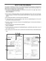
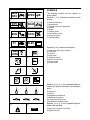


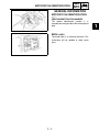
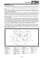
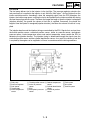

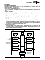
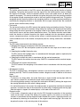
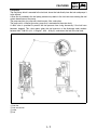

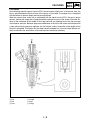
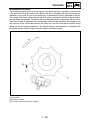
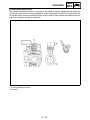
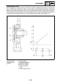
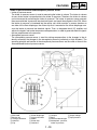
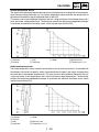
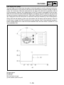
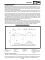
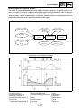
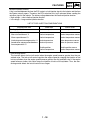
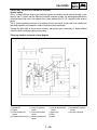
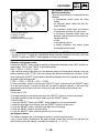
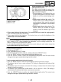
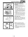
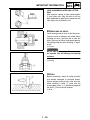
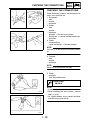
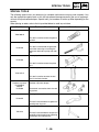
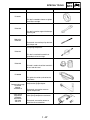
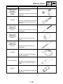
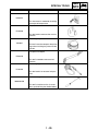
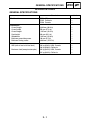
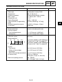
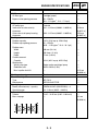
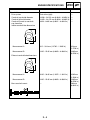
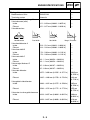
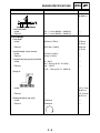
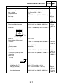
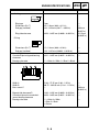
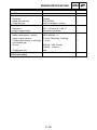
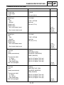
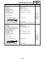
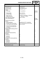
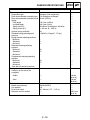
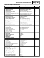
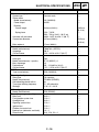
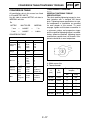
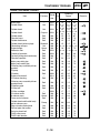
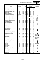
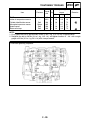
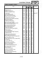

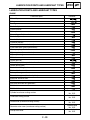
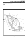
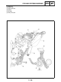
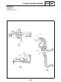
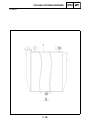
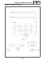
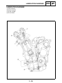
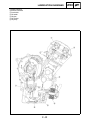
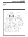
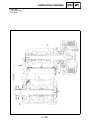
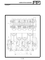
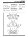
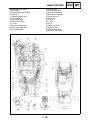
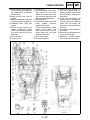
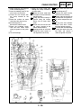
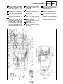
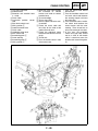
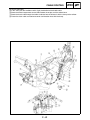
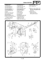

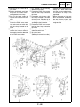
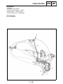
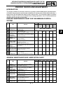
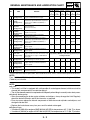
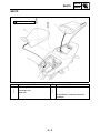
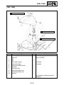
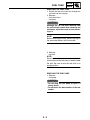
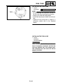
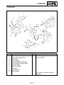
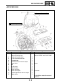
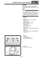
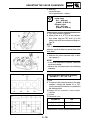
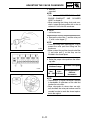
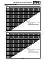
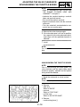
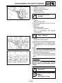
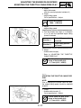

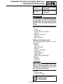
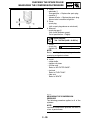
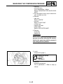
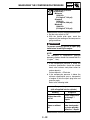
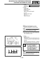
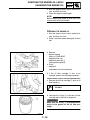
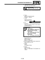
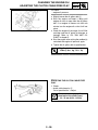
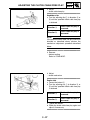
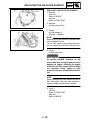
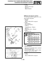
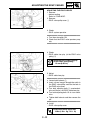
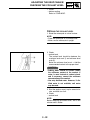
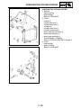
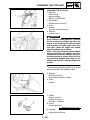
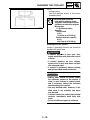
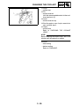
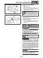
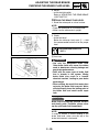
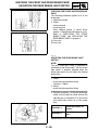
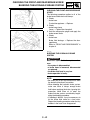
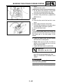
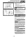
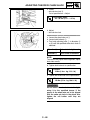
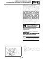
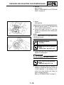
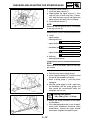
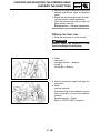
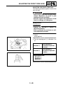
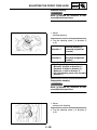
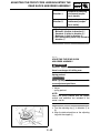
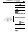
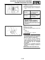
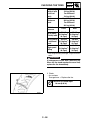
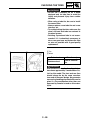
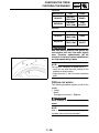
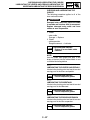
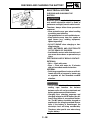
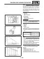
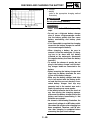
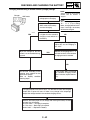
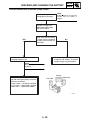
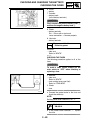
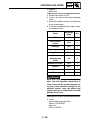
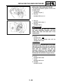
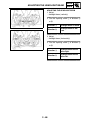
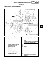
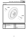
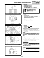
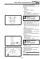
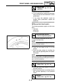
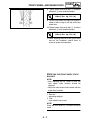
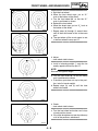
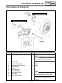
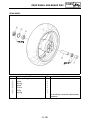
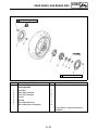
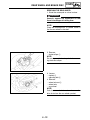
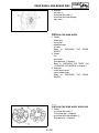
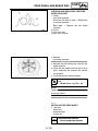
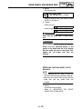
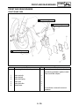
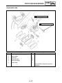
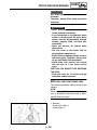
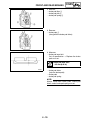
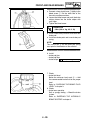

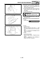

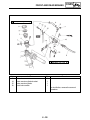
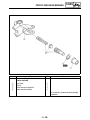
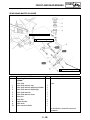
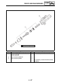
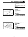
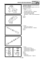
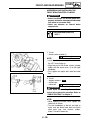
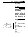
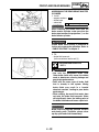
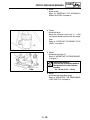
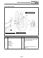
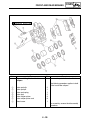
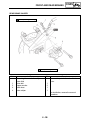
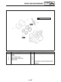
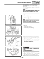
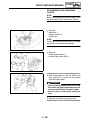
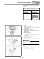
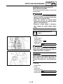

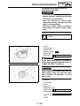
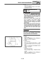
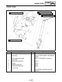
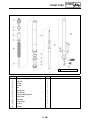
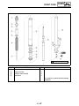
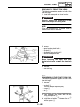
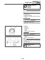
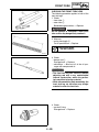
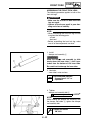
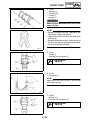
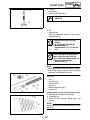
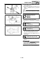
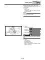
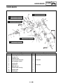
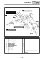
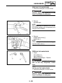
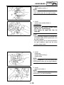
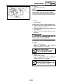
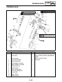
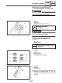
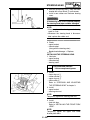

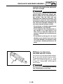
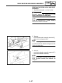
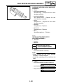
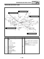
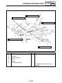
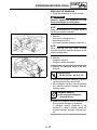
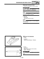
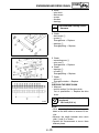
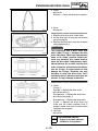

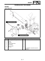
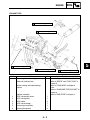
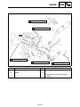

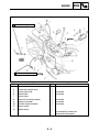
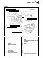
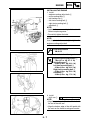
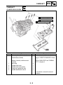
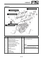
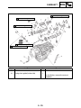
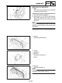
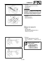
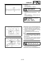
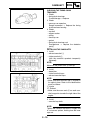
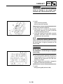
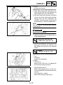
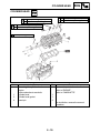
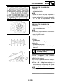

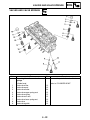
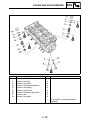
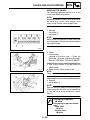
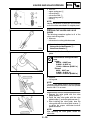
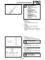
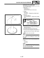
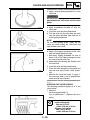
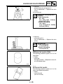
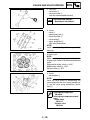
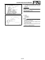
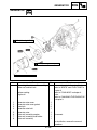

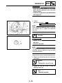
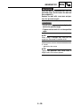
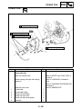
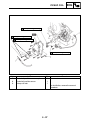
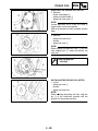
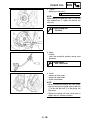
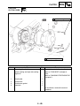
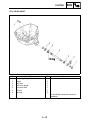
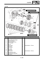
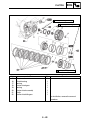
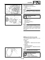
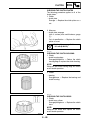
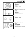
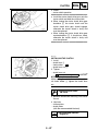
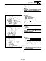


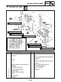
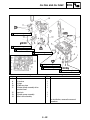
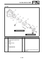
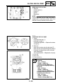
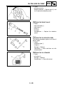
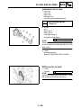
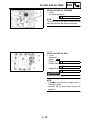
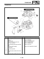
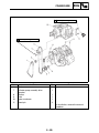
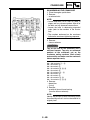
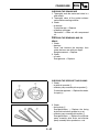
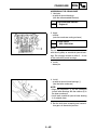

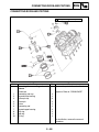
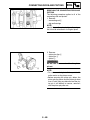
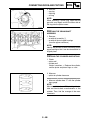
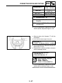
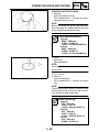

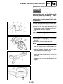
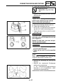
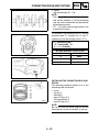
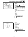
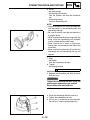
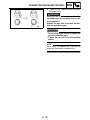
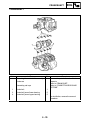
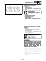
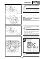
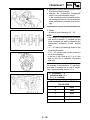
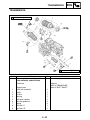
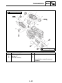
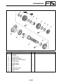
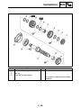
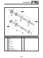
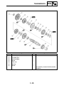
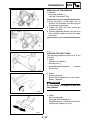
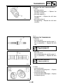
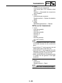
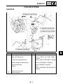
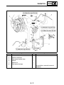
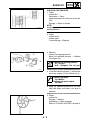
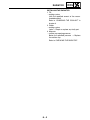
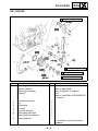
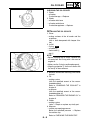
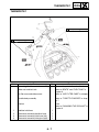
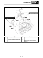
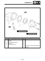
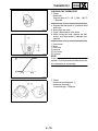
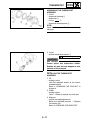
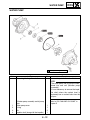
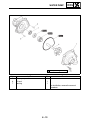
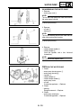
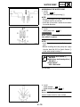
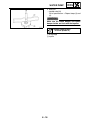
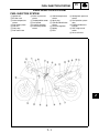
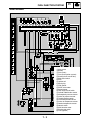
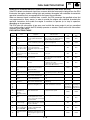
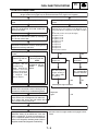
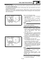
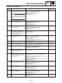
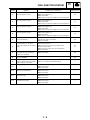
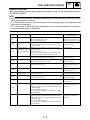
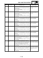
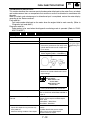
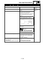
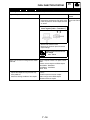

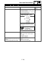
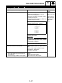
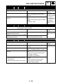
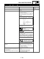
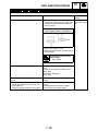
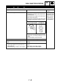
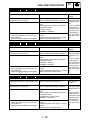
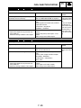
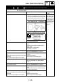
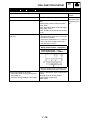
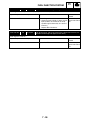
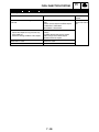
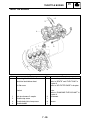
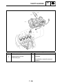
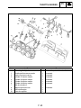
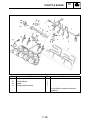

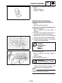
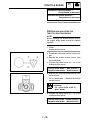
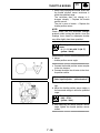
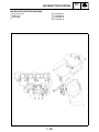
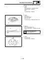
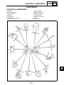
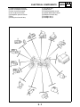
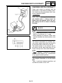
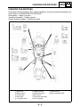
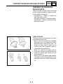
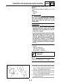
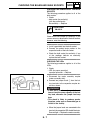

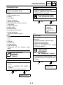
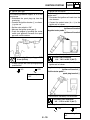

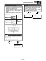

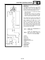
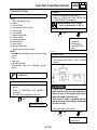
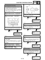

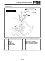
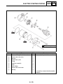
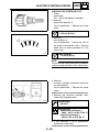

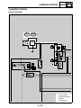
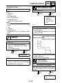
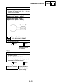
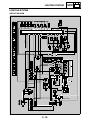
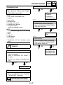
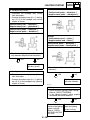
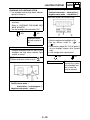
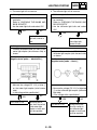
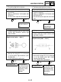
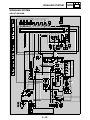
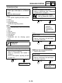
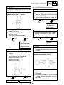
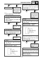
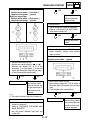
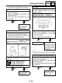
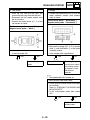
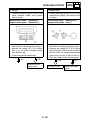
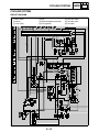
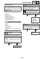
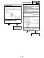
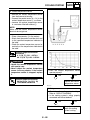
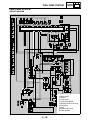
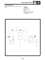
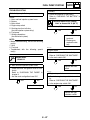
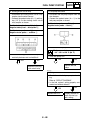
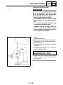
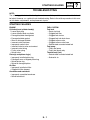
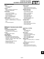
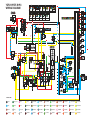

![Manuale Officina [ ITA ] Yamaha R1 2002-2003](http://vs1.manualzilla.com/store/data/006110674_1-52d32bbc9127defc0419b49b1226ec2b-150x150.png)