1
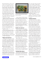
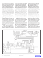
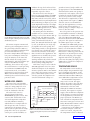
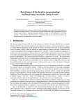
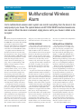
FEATURE ARTICLE
by Carl Smith
Multifunctional Wireless
Alarm
Carl’s multifunctional wireless alarm system can monitor everything from the doors to the
sump pump in your house.The system features an MC13192 SARD board and several wireless sensors. When the alarm is activated, simply place a call to your house to obtain a status report.
I
recently designed a multifunctional
wireless alarm system that’s based on
the IEEE 802.15.4 wireless data modem
specification. Implemented with
Freescale Semiconductor’s SimpleMAC
software, the system runs on microcontrollers in the MC9S08GT family.
A popular cartoon character who
decided to become an inventor was
the inspiration for my design, which I
call the Everything is OK Alarm. One
of his inventions looked like a smoke
alarm that beeped loudly and constantly. Over the loud beeping, he
yells, “This is an Everything is OK
Alarm. It keeps beeping as long as
everything is OK.”
Actually, my alarm is more like a
security alarm system, yet very different. How many times have you wondered if you closed the garage door
after leaving your house? Have you
ever worried about your heat shutting
off and your water pipes freezing? Or,
maybe you’ve worried during a storm
that your sump pump has quit and
your basement is filling with water.
A traditional security system activates only when something bad happens (e.g., a burglar opens a window).
It will not notify you when your front
door isn’t locked. Nor can it monitor
such things as water in your basement
and a particular room’s temperature.
My system can do all of these things
and more. You can keep tabs on everything from the position of your garage
doors to the water level in your hot tub.
The system’s remote wireless sensors
30
Issue 194 September 2006
will give you a status report when you
call home and enter your security code.
also use it to monitor the temperature
near water pipes.
SYSTEM OVERVIEW
INSTALLATION & OPERATION
The system’s base unit receives status data from the remote wireless sensors and acts on it appropriately. It
lights an LED to alert you when an
error condition exists. You can press a
button for an audio report from the
remote sensors. If you’re away from
home, you can call the phone number
connected to the base unit, enter a
security code, and receive the report.
A garage door module is attached to
the inside of a garage door. It transmits the door’s position to the base
unit. An error message is sent if the
door is open.
A water level detection module periodically transmits water level data to
the base station. It sends an error message if the level is above a calibrated
trip point. It uses a flexible clear vinyl
tube to detect the water level. You can
place the tube in a sump pump hole,
bathtub, or hot tub in order to prevent
overflows that can cause water damage.
A temperature module periodically
takes the current temperature and
compares it to upper and lower limits
that you set. If the temperature is
beyond either limit, the module transmits an error message to the base station; otherwise, it transmits a nonerror message. The reading is also
transmitted to the base station. This
module allows you to monitor heating
and air conditioning systems. You can
The base unit is installed by connecting a phone line to an RJ11 wall
jack. You can plug a telephone into
the jack. Power can be supplied to the
base unit with the wall plug power
supply or a USB cable plugged into a
PC’s USB port. (I used the power supply that came with the Freescale
Wireless Design Challenge contest kit.)
A speaker is plugged into the speaker
jack. A set of unamplified computer
speakers is sufficient for this purpose.
Now let’s focus on the processes of
powering up and programming the
system. Programming is necessary at
power-up. The base unit uses a builtin speech synthesizer to guide you
through the programming process. It
asks for a network number and security code for dial-up access to be programmed with the push buttons on a
Freescale MC13192-EVB. The purpose
of the network number is to allow
more than one system to work without each reacting to the sensor messages from the others. The base unit
won’t act on messages unless the data
packet is properly formatted and the
network number matches. The network number must be the same for
the base unit and all of the remote
sensors that the base unit monitors.
At this point, the unit will announce
that the system is ready to use.
The unit lights LED4 on the
CIRCUIT CELLAR®
www.circuitcellar.com
MC13192-EVB when a remote sensor
reports an error condition. You can
press S1 for a summary report from
the speech synthesizer. The system
plays a message, “Everything is OK,”
when the remote sensors don’t report
errors. It mentions errors if they
occur. For example, if a garage door
sensor programmed as device number
two senses an open door, the system
says, “Garage door two is open.” You
can press S2 for a full report, which
sounds something like, “Garage door
one is closed. Garage door two is open.
Temperature sensor one is OK. Water
level sensor one is OK.”
When you’re away from home, you
can check the status of the system by
calling the phone line attached to the
base unit. After several rings the base
unit will pick up the phone line and
ask for your security code. You’ll then
enter your code (programmed during
the setup phase) using the touch-tone
buttons on your phone. The system
will time out and hang up the line in
10 s if you don’t respond to the
prompts; it will hang up if you enter
an incorrect code.
When you enter the correct code,
the system automatically provides you
with a short summary report. After
that, the system tells you to press 1
for the full report or 2 to terminate
the call. If you press 2 or don’t respond
to the prompt in 10 s, the system says
“goodbye” and hangs up.
GARAGE DOOR MODULE
Installing and setting up the garage
door module is easy. When the unit is
powered up, it flashes all four LEDs so
you know that programming is required.
The network number is entered first
using S101 to cycle through 1 to 15.
The currently selected number is displayed in binary on the four LEDs.
When the desired number is reached,
S102 enters the selection.
Next, the unit flashes three of the
LEDs so that you know to enter the
device number. You select the device
number the same way you select the
network number. After entering the
device number, the unit blinks all of the
LEDs three times to let you know that
programming is complete and the device
is going into normal operating mode.
www.circuitcellar.com
Photo 1—The base unit’s MC13192-EVB and EMIC
module were mounted on a standard perfboard. The
rest of the unit was built with point-to-point wiring techniques on the perfboard.
Device numbers should be unique
for each type of sensor, but they don’t
have to be unique across all of the sensor types. The garage door sensor
should be mounted on the inside of
the garage door with the solder side of
the Freescale MC13192 SARD PCB
facing toward the door. When the door
is open and horizontal in the upper
track, the component side of the PCB
should face downward.
WATER LEVEL MODULE
For the water level sensor module,
you must program the network number
and device number. The module blinks
two LEDs to indicate that you must
program the trip point. Press the S101
switch to start the trip point calibration.
LED1 blinks rapidly to indicate the
level programming mode. The rate of
blinking slows as the sensor tube submerges deeper in water. This enables
you to test the sensor.
When dealing with a sump pump
hole, where filling the hole with water
during the calibration process isn’t
practical, you can calibrate the sensor
with a glass of water. Use a marker or
a piece of tape to mark the desired
depth on the sensor tube and then
submerge it up to that point in the
glass of water. Press S102 to set the
trip point. You can then move the sensor and tube into the sump hole.
Mount the tube so the marked point is
at the level where an alarm is desired.
TEMPERATURE MODULE
To program the temperature sensor
module, set the network number and
device number in the same way you
set the garage door sensor. Following
CIRCUIT CELLAR®
this, set the upper and lower temperature limits. LED1 and LED2 flash to
prompt you to program of the upper
temperature limit tens digit. Press S101
to cycle the value and S102 to enter.
LED3 and LED4 blink to indicate
that the upper limit ones digit should
be entered in the same manner. The
two inner LEDs prompt the entry of
the lower limit tens digit. The outer
two LEDs are for the entry of the
lower limit ones digit.
That’s it. When you’re done programming, you can place the temperature sensor in the area that you want
to monitor.
HARDWARE DESIGN
The base unit is the most complicated design in the system. It must be
able to receive and store the messages
from the remote sensors, provide synthesized audio output (for status
reports, prompts, and menu selections), recognize DTMF tones to
respond to the menu selections, and,
of course, interface to the telephone
line in order to answer incoming calls.
The MC13192-EVB PCB that came
with the contest kit is the main part of
the base unit. It’s mounted on a prototyping perfboard, where the rest of the
circuitry was constructed with point-topoint wiring techniques (see Photo 1).
The MC13192-EVB provides 5 V to
the rest of the circuitry with a tap
into the S106 power switch leads (see
Figure 1, p. 32). The I/O from J107 is
connected to the prototyping board via
a ribbon cable. The serial port at J103
is connected to the perfboard with a
D-sub connector to interface to the
speech synthesizer module.
A Grand Idea Studio Emic text-tospeech module (distributed by
Parallax) provides the speech synthesis
functions. The module supplies highquality speech synthesis, and it interfaces with a standard TTL serial interface at 2,400 bps. Its connections to the
microcontroller include a SERIAL IN, a
SERIAL OUT, and a BUSY line to indicate when the module is busy speaking and cannot respond to commands.
The Emic uses TTL voltage levels
for the serial input and output rather
than the full RS-232 voltage levels
output by the MC13192-EVB. This
Issue 194 September 2006
31
was a good decision by the designers.
In most applications, the module simply would be connected to the serial
outputs of a microcontroller, but it
makes level translation circuitry necessary to interface to the MC13192EVB. I used a Linear Technologies
LT1081 level translator chip for this
job. Its function is similar to the popular MAX232 family and all of its derivatives, any of which would have been
well suited for the job. I just happened
to have an LT1081 on hand.
The Emic has an onboard audio
amplifier that can power external
speakers up to 300 mW, which is sufficient volume for connecting to an
unamplified speaker. It also has a separate analog output, which is connected to the telephone interface circuitry
to send audio signals over the telephone line. An analog input allows the
Emic to amplify audio from the phone
line, which is useful for debugging
purposes.
Sending ASCII text commands to
the serial input at 2,400 bps controls
the Emic. Commands are available to
convert text to speech, set the volume
level, set the speed and pitch of the
synthesized speech, check the Emic
version, turn on the audio input, and
open a Help menu. You can also store,
delete, and recall abbreviations.
I used only the reset and text-tospeech conversion commands for this
project. To reset, simply send a reset;
command to the module and wait for
the busy line to go inactive. To convert text to speech, send the text to be
spoken to the module preceded by the
“say=” command and follow up with a
semicolon to finish the command. For
example, to say “hello,” send the
say=hello; command.
The Emic’s busy line is connected
to a logic input on the MC13192-EVB.
This allows the software to wait for
the Emic to finish one command
before starting the next. Note that all
of the logic external to the MC13192EVB is 5-V logic. The MC13192-EVB
uses 3-V logic, so a ULN2003 IC consisting of seven open-collector transistors with integrated base resistors is
used for logic level translation for all
of the logic inputs to the MC13192EVB. The internal pull-ups on the
MC13192-EVB’s logic lines are
enabled in the software to ensure a
logic high when the open collector
transistor is off.
The audio generated by the Emic
module is injected into the phone line
through a telephone direct access
arrangement circuit built around a
Cermetek Microelectronics CH1837
DAA module that provides some
surge and protection circuitry, isolation, a hybrid two- to four-wire converter that separates the transmitted
and received audio, ring indication,
and hook control. External to the
DAA is more robust line protection
circuitry and EMI suppression circuitry that includes capacitors from tip
and ring to ground to bypass EMI,
fuses for surge protection, and a transient voltage suppression diode across
the tip and ring. The transmit connections go to the Emic speech module.
The receive line is routed to the
DTMF detection circuit. The ring indicator and off hook control lines are con-
Figure 1—The main components in the base unit are a Freescale MC13192-EVB, an Emic text-to-speech module, and a Cermetek CH1837A direct access arrangement.
32
Issue 194 September 2006
CIRCUIT CELLAR®
www.circuitcellar.com
nected to the microcontroller through 5- to 3-V
logic level translation.
DTMF detection is performed by a BG Micro
SSI204 DTMF detection
IC. Given more development time, I would have
been able to implement a
DTMF detection routine
in software, but I
would’ve needed hardware
to amplify the incoming
phone line audio to a
range suitable for the
ADC on the GT60 proces- Figure 2—The MPX2010GS sensor measures the water level by the air pressure in the tube. The op-amp circuitry changes the differential
sensor signal to a ground-referenced signal and amplifies the signal to a range appropriate for the MC13192 SARD board’s analog input.
sor. The SSI204 chip
interfaces directly to the
MC13192-SARD PCB to detect the
DAA audio output with nothing more
hardware integration on the
position of the garage door. The
than a 0.1-µF capacitor.
MC13192-SARD, the design of this
MC13192-SARD periodically wakes
sensor was software only, but this proup, checks the accelerometer, and
vided an easy starting point to start
GARAGE DOOR SENSOR
sends an error code when –1 g (due to
software development and quickly
I started the remote sensor design
the force of gravity) is seen. The PCB
implement a sensor for the validation
with the garage door module because
must be mounted on the garage door
of the base unit’s reception abilities.
all of the required hardware was
with the solder side toward the door
The garage door module uses the
already part of the MC13192-SARD
so that it is horizontal and upside
Freescale MMA1260D 1.5-g z-axis
PCB, with one minor exception I will
down on the raised garage door.
accelerometer included on the
discuss later. With the high level of
www.circuitcellar.com
CIRCUIT CELLAR®
Issue 194 September 2006
33
The water level sensor module
enables you to monitor the level of
water in a sump pump hole. You
could also use it to detect water
levels in a bathtub or hot tub.
The water level sensor is
designed around a Freescale
MPXM2010G pressure sensor. This
sensor works well because it has
on-board temperature compensation and calibration circuitry,
which allows for a simple and reliable design. One end of a tube is
connected to the pressure sensor
and the other is placed in the sump
pump hole. The use of a pressure
sensor gives you the flexibility to
34
Issue 194 September 2006
The temperature sensor module is
another simple design. With the high
level of hardware integration on the
MC13192-SARD PCB, all you need is
a National Semiconductor LM34 precision Fahrenheit temperature sensor.
The measurable temperature
range is 0° to 256°F. The upper
+
limit is the result of the 8-bit data
9-V Battery
field in which the temperature is
5V
transmitted to the base. And
+
although the LM34 can measure
Freescale 13192 SARD
TP104
below 0°, this requires a negative
LED 1 LED 2 LED 3 LED 4
supply. That would have complicatS101
S102
S103
S104
ed the design so it wasn’t necessary
5V
for the application (to measure the
1
Digital/analog I/O J105
J101 BDM
proper operation of an HVAC sysVS
J105/3
J101/2
tem or watch for temperatures that
2
LM34 VOUT
may cause water pipes to freeze and
GND
burst). Measurement from 0° to 256°F
3
is sufficient for these purposes.
Connections for the LM34 sensor
Figure 3—The temperature sensor’s layout is fairly simple. The
are shown in Figure 3. Like the
LM34 is connected to the MC13192 SARD PCB’s 5-V supply,
water level sensor, 5-V power for
ground, and analog input. The pressure sensor hardware is
the temperature sensor is obtained
complete.
–
WATER LEVEL SENSOR
TEMPERATURE SENSOR
Power
–
The minor exception I mentioned
earlier is power management. One of
the great things about the 802.15.4
wireless networking standard and the
protocols that build on it (e.g.,
Freescale’s Simple MAC and Zigbee) is
low-power consumption. Units can
sleep the majority of the time and
thereby reduce the average power.
Unfortunately, with the hardware provided for the Wireless Design
Challenge, there was no way to put
the accelerometers or serial port chip
on the MC13192-SARD board into
Power Down mode, so I couldn’t
implement a low-power Sleep mode.
With a custom PCB, I could have
included power control for these components as well.
ground-referenced, single-ended voltage appropriate for the MC9S08GT60
microcontroller’s ADC. An op-amp is
connected to each output of the sensor
to buffer the signals and add a small
offset to the positive sensor output.
The difference is amplified by a third
op-amp circuit with a gain of 1,000 to
scale the sensor’s several millivolt
range (in this application) to a range
useful for the microcontroller. A
fourth op-amp is a simple voltage follower to drive the ADC.
Five-volt power for the pressure sensor and amplifier circuitry is obtained
by a connection to TP104 on the solder
side of the MC13192-SARD PCB.
Ground is obtained from the J101 BDM
port pin 2. The signal is connected to
the ATD2 input on pin 3 of J105.
The MC13192-SARD PCB, pressure
sensor, amplifier circuit board, and 9-V
battery were all mounted in a black
plastic project case for protection.
Instead of a 9-V battery, power may be
supplied by an external power source,
such as the wall plug power supply
supplied with the kit, by plugging
power into the J106 power plug on the
SARD. Photo 2 shows the completed
water level sensor.
RS-232
Photo 2—Check out the completed water level sensor
unit. The MC13192 SARD PCB, pressure sensor PCB,
battery, and signal conditioning circuit are mounted in a
standard black project box.
calibrate the trip level and avoid electrical contacts that may corrode when
repeatedly exposed to water.
The water level sensor design is
based on a Freescale MC13192-SARD
PCB, a MPXM2010 breakaway board
that came with the contest kit, and an
additional board for signal amplification
and conditioning (see Figure 2, p.33). The
signal amplification circuit is an adaptation of the one described in Michelle
Clifford’s 2004 application note, “Water
Level Monitoring” (Freescale).
The Analog Devices AD8544 is
available only in a surface-mount
package, so I used two AD822 dual opamps instead. The AD822 is a DIP
package, which makes construction
easier, and I already had some on
hand. The AD8544 should work equally well, as should any 5-V single supply capable rail-to-rail op-amp. The
other change I made to the application
note design was to double the gain to
increase the sensitivity in the range
that is useful for this application. The
application note describes the process
of measuring the water level in a
washing machine tub, which is much
deeper than the range necessary to
detect a filling sump pump hole.
I will leave it up to you to read the
AN1950 application note for a more
detailed description of the amplifier
circuit’s operation. But let me summarize it here. The pressure sensor’s output is a differential signal not referenced to ground. The amplifier converts this differential voltage to a
CIRCUIT CELLAR®
www.circuitcellar.com
MICROCONTROLLERS
What Are You
Made Of?
eZ430-F2013
Complete
Development Tool
Only $15
Regular Price $20
WIN
one of three
DLP® HDTVs
Show us what you’re made of by entering the MSP430 eZ Design Contest. Pit yourself
against other top designers from around the world by submitting your design featuring
TI’s MSP430 – the world’s lowest power microcontroller.
Easy to Participate
• No purchase necessary to enter
• Test drive the eZ430-F2013 Development
Tool on TechOnLine’s VirtuaLab for free
• Receive a 25% discount on the
eZ430-F2013
• Submit your entry today
Easy to Win
• Submit your entry by October 2, 2006
• Grand prize, first place and second place
winners will each receive a DLP® HDTV,
airfare, lodging and entry to the MSP430
Advanced Technical Conference in Dallas,
Texas November 7-9
www.ti.com/designmsp430
Technology for Innovators, the red/black banner and DLP are trademarks of Texas Instruments. 1617AO
© 2006 TI
Technology for Innovators
TM
via a connection to the TP104 on the
solder side of the MC13192-SARD
PCB. Ground is obtained from the
J101 BDM port pin 2. The signal is
connected to the ATD2 input on pin 3
of J105.
“N” Netnum +48
78
ASCII
1 Byte
1 Bytes
“T” devType+48 “D” Devnum+48 “E”
Error+48
84
ASCII
68
ASCII
69
ASCII
1 Byte 1 Byte 1 Byte
1 Byte
1 Byte
1Byte
“A”
65
1 Byte
dAta
1 Byte
<CR>
13
1 Byte
<LF>
10
1 Byte
Figure 4—Take a look at the wireless data packet format. Twelve bytes carry the network number, device type,
device number, error code, and data. All but the data have 48 added to push them into printable ASCII characters.
The letters between fields allow the detection of a valid packet. With the <CR><LF>, they make debugging easy by
dumping packets to a terminal window.
SOFTWARE DESIGN
For software development, I used
the Metrowerks Codewarrior development environment that came with the
contest kit. Freescale’s Simple MAC
software provided everything neces-
sary to get data flying between the
sensors and base unit. All I had to
worry about was the data format to
transmit the sensor information.
I decided on the data packet format
4th International System-on-Chip (SoC)
Conference and Exhibit
November 1 & 2, 2006
Radisson Hotel Newport Beach, California
Early Bird Registration Open Now
Register Today & Save!
www.SoCconference.com
The Most Targeted & Informative
System-on-Chip (SoC)
Conference & Exhibit
Event of the Year!
Don’t Miss Out!
For Information and Questions,
Please Contact SoC Conference Organizing Committee:
[email protected]
949-851-1714
www.SavantCompany.com
36
Issue 194 September 2006
CIRCUIT CELLAR®
shown in Figure 4. NetNum is the network number, which allows more
than one system to coexist. The base
unit reacts only to messages with a
matching network number and properly formatted data packet.
DevType identifies the sensor type.
For example, the garage door sensor was
assigned a device type of 1. DevNum
allows more than one of the same sensor type to be identified by the base
unit. Error is a “1” for a problem that
requires attention and a “0” otherwise. Data is the actual sensor data.
The letters between fields and the
CRLF allow for the detection of a
properly formatted data packet. They
make debugging easier by allowing
the raw packets to be dumped out the
serial port and read with a terminal
program. (The first four fields are
bytes, and 48 is added to transmit in
readable ASCII characters.)
The remainder of the software for
the remote sensors is simple set-up
and calibration code. It’s followed by a
loop that periodically wakes up,
checks the sensor, transmits the data,
and goes back to sleep. The remainder
of the base unit software is the set-up
code followed by code to monitor the
sensor data (and react appropriately)
and to monitor and process incoming
telephone calls.
IMPROVEMENTS
As usual, I thought of numerous
ways to improve this project even
before I finished. For instance, integrating an Ethernet interface and
TCP/IP stack will allow for a web server that can be checked from anywhere
via an Internet connection. And since
text messages can be sent to some cell
phones by e-mail, this will allow
alerts to be sent right to a cell phone.
Additional sensors will greatly
expand the system’s capabilities. I
want to design a sensor that can
check the position of a deadbolt lock,
www.circuitcellar.com
perhaps with a metal detection circuit. I also want to add smoke, carbon
monoxide, and combustible gas sensors. A sensor that can detect when
burners on my kitchen stove are in
use would be useful too.
PEACE OF MIND
This project turned out well for my
first wireless design and my first
attempt at using a Freescale HC08
microcontroller. The combination of
the MC9S08GT60 microcontroller,
the MC13192 RF transceiver, and the
Simple MAC software enabled me to
rapidly develop a complex wireless
system capable of monitoring several
useful remote sensors. I built the system quickly without the worries of
complicated RF design issues. As a
result, I was able to focus on developing the rest of the system.
Now you can build your own system. Hopefully, it will give you some
peace of mind when you’re away
from your house. Just think: now
you can check for problems anytime
you want. I
www.circuitcellar.com
Carl Smith ([email protected])
has more than 12 years of experience
in electronic engineering design. He
has worked on everything from highcurrent DC motor controllers to desktop computer components. Carl
earned a B.S.E.E. in 1992 and an
M.B.A. in 1994 from North Dakota
State University, but has been tinkering with electronics since his age was
measured in single digits.
PROJECT FILES
To download the code, go to ftp://ftp.
circuitcellar.com/pub/Circuit_Cellar/
2006/194.
RESOURCE
M. Clifford, “Water Level Monitoring,”
Freescale Semiconductor, AN1950,
rev. 3, 2004.
SOURCES
AD822 Op-amp
Analog Devices, Inc.
www.analog.com
CIRCUIT CELLAR®
SSI204 DTMF Detection IC
BG Micro
www.bgmicro.com
CH1837 DAA
Cermetek Microelectronics, Inc.
www.cermetek.com
MPXM2010GS Pressure sensor,
MC13192 EVB, MC13192 SARD, and
Simple MAC software
Freescale Semiconductor, Inc.
www.freescale.com
Emic Text-to-speech module
Grand Idea Studio
www.grandideastudio.com
LT1081 RS-232 Dual driver/receiver
Linear Technology Corp.
www.linear.com
LM34 Precision Fahrenheit sensor
National Semiconductor
www.national.com
ULN2003 Darlington array
ST Microelectronics
www.st.com
Issue 194 September 2006
37