1
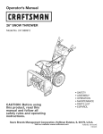
Operator's
Manual
CRRFr MRN
26" SNOW THROWER
Model No. 247.886914
,, SAFETY
o ASSEMBLY
OPERATION
MAINTENANCE
PARTS LIST
o ESPANOL
CAUTION" Before using this
product, read this manual and
follow all safety rules and operating
instructions.
Sears Brands Management
Corporation,
Visit our website:
Hoffman
Estates,
www.craftsman.com
IL 60179, U.S.A.
Form No. 769-051341
(June21,2013)
WarrantyStatement
..............................
SafeOperationPractices......................
Assembly
....................................
Operation..................................
Service&Maintenance
.......................
Page2
Pages3-6
Pages8-13
Pages14-17
Pages18-23
Off-Season
Storage
.............................
Page24
Troubleshooting
............................
Page26-27
PartsList...................................
Pages28-47
RepairProtectionAgreement
...................
Page50
Espa_ol
.........................................
Page51
CRAFTSMAN
TWOYEARFULLWARRANTY
FORTWOYEARS
fromthedateof purchase,
this productiswarrantedagainstanydefectsin materialor workmanship.
Defectiveproductwill receivefree
repairorfreereplacement
if repairisunavailable.
ADDITIONALLIFETIME
LIMITEDWARRANTY
on UPPERand LOWERCHUTE
FORASLONG
ASITISUSED
bytheoriginalownerafterthesecondyearfromthedateofpurchase,the
upperandlowerchuteofthissnowthrowerare
warrantedagainstanydefectsin materialor workmanship
asverifiedbya Sears
authorizedserviceprovider.With proofofpurchase,
youwill receivea new
chutefreeofcharge.Youareresponsible
for thelaborcostofinstallationandanycostincurredto verifythedefect.
Forwarrantycoverage
detailsto obtainrepairor replacement,
visitthewebsite:www.craftsman.com
ThiswarrantycoversONLY
defectsin materialandworkmanship.
Warrantycoverage
doesNOTinclude:
•
Expendable
itemsthatcanwearoutfrom normalusewithin thewarrantyperiod,includingbutnotlimitedto augers,augerpaddles,drift cutters,skid
shoes,shaveplate,shearpins,sparkplug,air cleaner,belts,andoilfilter.
•
Standard
maintenance
servicing,oil changes,
ortune-ups.
•
Tirereplacement
orrepaircausedbypunctures
from outsideobjects,suchasnails,thorns,stumps,orglass.
•
Tireor wheelreplacement
or repairresultingfrom normalwear,accident,or improperoperationormaintenance.
•
Repairsnecessary
becauseofoperatorabuse,includingbutnot limitedto damagecausedbyover-speeding
theengine,orfrom impactingobjectsthat
bendtheframe,augershaft,etc.
•
Repairsnecessary
becauseofoperatornegligence,
includingbutnot limitedto, electricalandmechanical
damagecausedbyimproperstorage,failureto
usethepropergradeandamountofengineoil,orfailureto maintaintheequipmentaccording
to theinstructions
containedinthe operator's
manual.
•
Engine(fuelsystem)cleaningorrepairscausedbyfueldeterminedto be contaminated
or oxidized(stale).Ingeneral,fuelshouldbe usedwithin 30days
ofitspurchasedate.
•
Normaldeteriorationandwearoftheexteriorfinishes,or productlabelreplacement.
Thiswarrantyisvoidif thisproductiseverusedwhileprovidingcommercial
services
or if rentedto anotherperson.
Thiswarrantygivesyouspecificlegalrights,andyoumayalsohaveotherrightswhichvaryfrom stateto state.
SearsBrandsManagement
Corporation,
NoffmanEstates,
IL60179
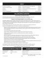
Engine Oil:
5W-30
Model Number
Fuel:
Unleaded Gasoline
Serial Number
Engine:
MTD
Date of Purchase
Record the model number, serial number,
and date of purchase above.
© Sears Brands, LLC
2
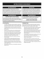
Thissymbolpointsout importantsafety instructionswhich, if not
followed, couldendangerthe personalsafetyand/or property of
yourself and others.Readandfollow all instructions in this manual
beforeattempting to operatethis machine.Failureto complywith these
instructions
may resultin personalinjury.Whenyou seethis symbol, HEED
ITSWARNING!
CALIFORNIA
PROPOSITION
65
EngineExhaust,someof its constituents,and certain vehiclecomponents
containor emit chemicalsknownto Stateof Californiato causecancerand
Thismachinewasbuilt to beoperatedaccordingto the safeoperation
practicesin this manual.Aswith anytype of powerequipment,
carelessnessor error on the part of the operatorcanresultin seriousinjury.
Thismachineiscapableof amputating fingers, hands,toesandfeet and
throwingdebris. Failureto observethefollowing safety instructions
could
resultin seriousinjuryor death.
Your Responsibility--Restrict the useof this powermachineto
personswho read,understandandfollow the warningsand instructionsin
this manualandon the machine.
SAVETHESEINSTRUCTIONS!
birth defectsor other reproductiveharm.
TRAINING
Disengage
all controlleversbeforestartingtheengine.
Read,understand,andfollowall instructionsonthe machineandinthe
manual(s)beforeattemptingto assembleandoperate.Failureto dosocan
resultinseriousinjury tothe operatorand/orbystanders.Keepthis manual
inasafeplaceforfutureandregularreferenceandfororderingreplacement
Adjustcollectorhousingheightto cleargravelor crushedrocksurfaces.
parts.
Letengineandmachineadjustto outdoortemperaturebeforestartingto
clearsnow.
Befamiliarwith all controlsandtheir properoperation.Knowhowto stop
the machineanddisengagethemquickly.
Neverallowchildrenunder14yearsof ageto operatethis machine.Children
14andovershouldreadandunderstandthe instructionsandsafeoperation
practicesinthis manualandonthe machineandbetrainedandsupervised
byanadult.
Neverallowadultsto operatethismachinewithout properinstruction.
Thrownobjectscancauseseriouspersonalinjury.Planyoursnow-throwing
patternto avoiddischargeof materialtowardroads,bystandersandthe like.
Keepbystanders,
petsandchildrenat least75feetfrom the machinewhileit
isin operation.Stopmachineif anyoneentersthe area.
Exercise
cautionto avoidslippingor falling, especiallywhenoperatingin
reverse.
PREPARATION
Thoroughlyinspect
the areawherethe equipmentisto beused.Removeall
doormats,newspapers,
sleds,boards,wiresandotherforeignobjects,which
couldbetrippedoveror thrownbythe auger/impeller.
Alwayswearsafetyglasses
or eyeshieldsduringoperationandwhile
performinganadjustmentor repairto protectyoureyes.Thrownobjects
whichricochetcancauseseriousinjuryto the eyes.
Donot operatewithout wearingadequatewinteroutergarments.Donot
wearjewelry,longscarvesorotherlooseclothing,whichcouldbecome
entangledin movingparts.Wearfootwearwhichwill improve
footing on
slipperysurfaces.
Usea groundedthree-wireextensioncordandreceptacleforall machines
with electricstartengines.
Neverattemptto makeanyadjustmentswhileengineisrunning,except
wherespecificallyrecommended
inthe operator'smanual.
Safe Handling
of Gasoline:
Toavoid personalinjuryor property damageuseextreme carein handling
gasoline.Gasolineisextremely flammable andthe vaporsareexplosive.
Seriouspersonalinjurycan occurwhengasolineis spilledon yourselfor your
clotheswhichcanignite. Washyour skinandchangeclothesimmediately.
Useonlyanapprovedgasolinecontainer.
Neverfill containersinsidea vehicleor ona truckor trailerbedwitha plastic
liner.Alwaysplacecontainersonthe groundawayfrom yourvehiclebefore
filling.
Whenpractical,removegas-poweredequipmentfrom the truckor
trailer andrefuelit onthe ground.Ifthisis not possible,thenrefuelsuch
equipmenton atrailerwith aportablecontainer,ratherthanfrom agasoline
dispensernozzle.
Keepthe nozzleincontactwith the rim ofthe fuel tankor containeropening
at all timesuntil fuelingiscomplete.Donot usea nozzlelock-opendevice.
Extinguishall cigarettes,cigars,pipesandothersourcesof ignition.
Neverfuel machineindoors.
Neverremovegascapor addfuel whilethe engineishot or running.Allow
engineto coolat leasttwo minutesbeforerefueling.
Neveroverfill fueltank.Filltankto nomorethan1/2inchbelowbottomof
filler neckto allowspacefor fuelexpansion.
Replace
gasolinecapandtightensecurely.
Ifgasolineisspilled,wipeit offthe engineandequipment.Moveunitto
anotherarea.Wait.5minutesbeforestartingtheengine.
To
reduce
firehazards,
keep
machine
free
ofgrass,
leaves,
orother
debris
build-up.
Clean
upoilorfuelspillage
and
remove
any
fuelsoaked
debris.
Never
store
themachine
orfuelcontainer
inside
where
there
isanopen
flame,
spark
orpilot
light
asonawater
heater,
space
heater,
furnace,
clothes
dryer
orother
gas
appliances.
OPERATION
Useonlyattachmentsandaccessories
approvedbythe manufacturer(e.g.
wheelweights,tire chains,cabsetc.).
Whenstartingengine,pull cordslowlyuntil resistanceisfelt, thenpull
rapidly.Rapidretractionofstartercord(kickback)will pullhandandarm
towardenginefasterthanyoucanletgo. Brokenbones,fractures,bruisesor
sprainscouldresult.
Ifsituationsoccurwhicharenot coveredinthismanual,usecareandgood
judgment.
Donot put handsor feetnearrotatingparts,inthe auger/impellerhousing
or chuteassembly.
Contactwith the rotatingpartscanamputatehandsand
feet.
CLEARING
Theauger/impellercontrolleverisasafetydevice.Neverbypassits
operation.Doingsomakesthe machineunsafeandmaycausepersonal
injury.
Handcontactwith the rotatingimpellerinsidethedischargechuteisthe most
commoncauseof injuryassociated
with snowthrowers.Neveruseyourhandto
cleanout the dischargechute.
Thecontrolleversmustoperateeasilyin bothdirectionsandautomatically
returnto the disengagedpositionwhenreleased.
Toclearthe chute:
A CLOGGED
DISCHARGE
CHUTE
a.
SHUTTHE
ENGINE
OFF!
Neveroperatewith amissingor damagedchuteassembly.Keepall safety
devicesin placeandworking.
b.
Wait 10secondsto besurethe impellerbladeshavestopped
rotating.
Neverrunanengineindoors
or inapoorlyventilatedarea.Engineexhaust
containscarbonmonoxide,anodorlessanddeadlygas.
c.
Alwaysuseaclean-outtool, not yourhands.
MAINTENANCE
& STORAGE
Donot operatemachinewhileunderthe influence
of alcoholor drugs.
Nevertamperwith safetydevices.Checktheirproperoperationregularly.
Referto the maintenanceandadjustmentsectionsof thismanual.
Mufflerandenginebecomehot andcancauseaburn.Donot touch.Keep
childrenaway.
Beforecleaning,repairing,or inspecting
machinedisengageall control
leversandstopthe engine.Waituntil the auger/impellercometo acomplete
stop.Disconnect
thesparkplugwire andgroundagainstthe engineto
preventunintendedstarting.
Exercise
extremecautionwhenoperatingonor crossinggravelsurfaces.Stay
alertforhiddenhazardsor traffic.
Exercise
cautionwhenchangingdirectionandwhileoperatingonslopes.Do
not operateon steepslopes.
Checkboltsandscrewsforpropertightnessat frequentintervals
to keepthe
machineinsafeworkingcondition.Also,visuallyinspect
machineforany
damage.
Planyoursnow-throwingpatternto avoiddischargetowardswindows,
walls,carsetc.Thus,avoidingpossiblepropertydamageor personalinjury
causedbyaricochet.
Donot changethe enginegovernorsettingor over-speed
the engine.The
governorcontrolsthe maximumsafeoperatingspeedof the engine.
Neverdirectdischargeat children,bystanders
andpetsor allowanyonein
front of the machine.
Snowthrowershaveplatesandskidshoesaresubjectto wearanddamage.
Foryoursafetyprotection,frequentlycheckall componentsandreplace
with originalequipmentmanufacturer's
(OEM)partsonlyaslistedinthe
Partspagesofthisoperator'smanual.Useof partswhichdonot meetthe
originalequipmentspecifications
mayleadto improper
performanceand
compromisesafety!
Donot overloadmachinecapacitybyattemptingto clearsnowat too fastof
arate.
Neveroperatethismachinewithoutgoodvisibilityor light. Alwaysbesureof
yourfootingandkeepafirm holdon the handles.Walk,neverrun.
Disengage
powerto the auger/impellerwhen transportingor not in use.
Checkcontrolleversperiodicallyto verifytheyengageanddisengage
properlyandadjust,if necessary.
Referto the adjustmentsectioninthis
operator'smanualfor instructions.
Neveroperatemachineat hightransportspeedsonslipperysurfaces.Look
downandbehindandusecarewhenbackingup.
If the machineshouldstartto vibrateabnormally,stopthe engine,
disconnectthe sparkplugwire andgroundit againstthe engine.Inspect
thoroughlyfordamage.Repairanydamagebeforestartingandoperating.
Maintainor replacesafetyandinstruction
labels,asnecessary.
Observe
properdisposallawsandregulationsforgas,oil,etc.to protectthe
environment.
Disengage
all controlleversandstopenginebeforeyouleavethe operating
position(behindthe handles).Waituntil the auger/impellercomesto
acompletestopbeforeuncloggingthe chuteassembly,
makingany
adjustments,or inspections.
Priorto storing,runmachineafewminutesto clearsnowfrom machineand
preventfreezeupof auger/impeller.
Neverstorethe machineor fuelcontainerinsidewherethereisanopen
flame,sparkor pilot light suchasa waterheater,furnace,clothesdryeretc.
Neverput yourhandin the dischargeor collectoropenings.Donot unclog
chuteassemblywhileengineis running.Shutoff engineandremainbehind
handlesuntil all movingpartshavestoppedbeforeunclogging.
Alwaysreferto the operator'smanualforproperinstructionsonoff-season
storage.
4
Checkfuelline,tank,cap,andfittings frequentlyfor cracksor leaks.Replace
if necessary.
Donot crankenginewith sparkplug removed.
Accordingto the ConsumerProductsSafetyCommission
(CPSC)
andthe
U.S.Environmental
ProtectionAgency(EPA),
thisproducthasan Average
Useful Life of seven(7)years,or 60 hoursofoperation.Atthe endof
the Average Useful Life havethe machineinspectedannuallybyan
authorizedservicedealerto ensurethat all mechanical
andsafetysystems
areworkingproperlyandnotwornexcessively.
Failureto dosocanresultin
accidents,
injuriesor death.
DO NOT MODIFY
ENGINE
Toavoidseriousinjuryor death,do notmodifyenginein anyway. Tampering
with the governorsetting canlead to arunawayengineandcauseit to
operateat unsafespeeds.Nevertamper with factory setting of engine
governor.
NOTICE
REGARDING
EMiSSiONS
Engineswhich are certifiedto complywith Californiaandfederal EPA
emissionregulations for SORE
(SmallOff RoadEquipment)arecertified
to operate on regularunleadedgasoline,and mayincludethe following
emissioncontrol systems:EngineModification (EM),OxidizingCatalyst(0C),
SecondaryAir injection(SAI)andThreeWayCatalyst(TWC)if soequipped.
SPARK ARRESTOR
e
This machineisequippedwith an internalcombustionengine andshould
not be usedon or near any unimprovedforest-covered,brushcoveredor
grass-coveredland unlessthe engine'sexhaust systemis equippedwith a
sparkarrestormeeting applicable localor state laws (if any).
Ira sparkarrestoris used,it shouldbe maintained in effective working order
bythe operator. In the State of Californiathe aboveisrequired bylaw (Section
4442of the CaliforniaPublicResourcesCode).Otherstates mayhavesimilar
laws.Federallaws apply on federal lands.
Asparkarrestorfor the muffler is availablethrough your nearestSearsParts
andRepairServiceCenter.
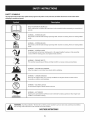
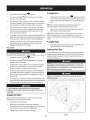
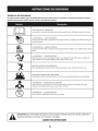
SAFETY
SYMBOLS
Thispage depicts and describes safety symbols that may appear on this product. Read, understand, and follow all instructions on the machine before
attempting
to assemble and operate.
READ THE OPERATOR'S MANUAL(S)
Read, understand,
and follow
all instructions
in the manual(s) before
attempting
to assemble
and
operate
WARNING--
ROTATING BLADES
Keep hands out of inlet and discharge openings
inside
WARNING--
blades
while
machine is running. There are rotating
blades
ROTATING AUGER
Do not put hands or feet near rotating
Contact with the rotating
WARNING--THROWN
This machine
parts, in the auger/impeller
parts can amputate
can cause serious personal
injury.
IS FLAMMABLE
before refueling.
CARBON MONOXIDE
Never run an engine indoors or in a poorly ventilated
monoxide, an odorless and deadly gas.
area. Engine exhaust contains carbon
ELECTRICAL SHOCK
Do not use the engine's
WARNING--
or chute assembly.
OBJECTS
Allow the engine to cool at least two minutes
WARNING--
housing
hands and feet.
may pick up and throw and objects which
WARNING--GASOLINE
WARNING--
machine is running. There are rotating
ROTATING BLADES
Keep hands out of inlet and discharge openings
inside
WARNING--
while
electric starter in the rain
HOT SURFACE
Engine parts, especially the muffler,
muffler to cool before touching.
WARNING:
Your Responsibility--Restrict
the warnings
and instructions
in this manual
become extremely
the use of this power machine
hot during
to persons
and on the machine.
SAVETHESEiNSTRUCTIONS!
6
operation.
Allow engine and
who read, understand
and follow
This page left intentionally blank.
7
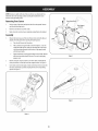
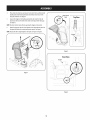
NOTE:References
to rightor left sideofthe snowthroweraredeterminedfrom
behindthe unit in theoperatingposition(standingdirectlybehindthe snow
thrower,facingthe handlepanel).
Removing FromCarton
1.
Cutthe cornersof the cartonandlaythe sidesflat on theground.Remove
anddiscardall packinginserts.
2.
Movethe snowthrowerout of the carton.
3.
Makecertainthe cartonhasbeencompletelyemptiedbeforediscardingit.
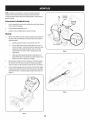
ChuteSupport
Bracket
Assembly
Observe
the lowerrearareaof the snowthrowerto besurebothcablesare
Chute
alignedwith rollerguidesbeforepivotingthe handleupward.
a.
Placetheshift [everinthe F6position.
b.
Pullup andbackonupperhandleasshownin Figure1.Asyouare
raisingthe handleupward,makesurethat bothendsof the center
cablearepositionedproperlyinthe brackets.Alignupperhandle
withthe lowerhandle.
c.
Tightenhandknobssecuringupperhandleto lowerhandle.Remove
anddiscardanyrubberbands,if present.Theyarefor packaging
purposesonly.
.J
Figure2
f
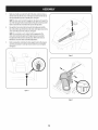
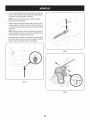
Removecotterpin, wingnut,andhexscrewfrom chutecontrolheadand
clevispinandbow-tiecotterpinfrom chutesupportbracket.SeeFigure2.
Insertchutecontrolrodinto inputof chutecontrolhead.Pushrodasfarinto
the chutecontrolheadaspossible,keepingthe holesin the rodpointing
upward.SeeFigure3.
/ .....
f
j
Rgure3
J
Figure 1
8
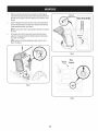
4.
Placechuteontochutebaseandensurechutecontrolrodispositionedunder
handlepanel.Installhexbolt previouslyremovedbut donot securewith
wingnut at thistime.SeeFigure4.
5.
Squeeze
the triggeronthe handlepaneljoystickandrotatethe chuteby
handto faceforward.Theholesinthe chutecontrolinputwill befacingup.
SeeFigure5.
TopView
NOTE:Thechutewill not rotatewithoutsqueezingthe triggeronthe joystick.
6.
Rotatethejoysticktothe oneo'clockpositionsothe sliverindicator
arrowon
the inputshaftbelowthe controlpanelpointsupward.SeeFigure6.
NOTE:Thejoystickwill be angledslightlyto the right.SeeFigure5& Figure6.
f
_J
Figure 5
f
FrontView
Joystick
//f
"_
\
Figure6
9
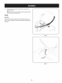
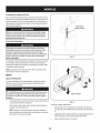
7.
f
Makesureall cablesareroutedto the left of the chutecontrolrod.Lineup
the holeinthe rodwith the arrowonthe inputshaftandinsertthe rodinto
the inputshaftbelowjoystickon handlepanel.SeeFigure7.
NOTE:
Thechutecontrolrodwill fit snugglyintothe inputshaft.Supportthe
rearofthe dashpanelwith onehandwhileinsertingthe rodwith yourother
handto ensurethe rodisinsertedall the wayinto the inputshaft.
8.
Nowpushthe chutecontrolrodbacktowardsthe handlepaneluntil the
holeinthe rodlinesup with the holeinthe chutecontrolinputclosestto the
chutecontrolhead.Insertthecotter pin.SeeFigure8.
NOTE:
Thesecondholeisusedto achievefurther engagementof the
chutecontrolrodinto the inputshaftif requiredandcanbeusedlater
foradjustmentif the chutedoesnot fully rotate.Referto the Service&
Maintenancesectionfor ChuteControlRodadjustments.
9.
/
Finishsecuringchutecontrolheadto chutesupportbracketwith wing nut,
andclevispinandbow-tiecotter pinremovedearlier.Donot overtighten.
SeeFigure9.
f
Figure8
f
Figure
7
\
Figure9
10
/
Checkthatall cablesareproperlyroutedthroughthe cableguideonthe
engine.SeeFigure10.
NOTE:Ifthe chutecontrolisnot assembledcorrectlyit will not movefreely
norwill it movefully to the rightandleft.
Set-Up
Shear Pins
Holesarelocatedin the plasticdashpanelfor convenientshearpinstorage.See
Figure11.Referto the Operationsectionfor moreinformationregardingshearpin
replacement.
I
J
Figure
10
f
J
Figure
11
11
ChuteClean-OutTool
f
_
Achuteclean-outtool isfastenedto the top ofthe augerhousingwith amounting
clip.SeeFigure12.Thetoolisdesignedto clearachuteassemblyof iceand
snow.Thisitemisfastenedwith acabletie at the factory.Cutthe cabletie before
operatingthesnowthrower.
ChuteClean-outTool
Neveruseyour handsto clearacloggedchuteassembly.Shutoff engine
and remainbehind handlesuntil all movingpartshavestoppedbefore
usingthe clean-outtool to clearthe chuteassembly.
TirePressure
Underany circumstancedo not exceedmanufacturer'srecommended
psi.
Equaltire pressureshouldbe maintained at all times. Excessivepressure
when seatingbeadsmaycausetireldm assemblyto burstwith force
sufficient to causeseriousinjury. Referto sidewall of tire for recommended
///
pressure.
.J
Thetiresareover-inflatedforshippingpurposes.Checkthe tire pressure
before
operatingthesnowthrower.Refertothe tire sidewall for tire manufacturer's
recommended
psianddeflate(orinflate)the tiresasnecessary.
Figure12
f
NOTE:Equaltire pressure
isto bemaintainedat all timesforperformancepurposes.
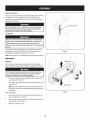
Adjustments
Smooth Surface
Skid Shoes
Thesnowthrowerskidshoes
areadjusted
upward
atthefactoryforshipping
purposes.
Adjustthemdownward,
ifdesired,
priortooperating
thesnowthrower.
It is notrecommended
that you operate this snowthrower on gravelas
it caneasilypickup andthrow loose gravel,causingpersonalinjuryor
damageto the snowthrower andsurroundingproperty.
Forclosesnowremovalon asmoothsurface,raiseskidshoeshigheronthe
augerhousing.Referto Figure13.
Useamiddleor lowerpositionwhenthe areato beclearedisuneven,suchas
agraveldriveway.
NOTE:Ifyouchooseto operatethe snowthroweron agravelsurface,keep
the skidshoesinpositionformaximumclearancebetweenthe groundand
the shaveplate.
\
Figure13
Toadjustthe skidshoes:
1.
Loosenthe four hexnuts (two oneachside)andcarriagebolts.Moveskid
shoesto desiredposition.SeeFigure13.
2.
Makecertainthe entirebottomsurfaceof skidshoeisagainstthe groundto
avoidunevenwearon the skidshoes.
3.
Retightennutsandboltssecurely.
UnevenSurface
12
Auger
Control
F
Priortooperatingyoursnowthrower,
carefullyreadandfollowall
instructions
below.Performall adjustments
toverifyyoursnowthroweris
operatingsafelyandproperly.
Checkthe adjustmentofthe augercontrolasfollows:
1.
Theaugercontrolislocatedon the left handle.SeeFigure14inset.When
the augercontrolisreleasedandinthe disengaged"up"position,the cable
shouldhaveverylittle slack.ItshouldNOTbetight.
2.
Ina well-ventilatedarea,start the snowthrowerengine.Referto Starting
the Engineinthe Operationsection.
3.
Whilestandinginthe operator'sposition(behindthe snowthrower),engage
the auger.
4.
Allowthe augerto remainengagedfor approximatelyten (10)seconds
beforereleasingthe augercontrol.Repeatthisseveraltimes.
Auger Control
J
/
f
5.
With theaugercontrolin the disengaged
"up" position,walkto the front of
the machine.
6.
Toreadjustthe controlcable,loosenthe upperhexbolt onthe augercable
bracket.SeeFigure14.
J
Figure14
Positionthe bracketupwardto providemoreslack(ordownwardto increase
cabletension).
8.
Retightenthe upperhexbolt.
9.
Repeatsteps2-6aboveto verifyproperadjustmenthasbeenachieved.
10.
Confirmthat the augerhascompletelystoppedrotatingandshowsNOsigns
of motion.Ifthe augershowsANYsignsof rotating,immediatelyreturnto
the operator'spositionandshut off the engine.WaitforALLmovingpartsto
stopbeforeadjustingthe augercontrol.
13
Shift Lever
J
Drive Control
J Four=WayChute ControP (Joystick)
Auger Control
Gas Cap
\
Wheel
Steering
Control
Chute Assembly
MUfti\er
Clean Out
Tool
i_e;:_lleStarte_
IF ELLEVE
Primer
Key
Throttle
Control
Choke
Control
/
Oil Drain
Electric Start
Button
Electric Starter Outlet
Figure15
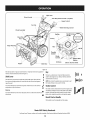
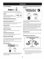
Nowthatyouhavesetupyoursnowthrower,it's importantto becomeacquainted
with its controlsandfeatures.Referto Figure15.
6
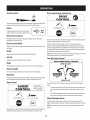
Shift [ever
,ey
Thekeyisasafetydevice.It mustbefully inserted
in
5
orderfor the enginetostart. Removethe keywhenthe
Theshift leverislocatedonthe right sideof the handlepanel.Placethe shift
leverintoanyof eightpositionsto controlthedirectionof travelandground
speed.Forward
4
NOTE:
Donot turn the
snowthrowerisnot
inignition
use. keyinan attemptto start
the engine.Doingsomaycauseit to break.
Yoursnowthrowerhassixforward(F)speeds.Positionone(1)isthe slowest
andpositionsix(6)isthe fastest.
t2
:3
Reverse
activated by turning the rotary choke knob to the CHOKE
position.Activating
the choke controlclosesthe choke
plate on the carburetorand aids instarting the engine.
Yoursnowthrowerhastwo reverse
(R)speeds.One(1)isthe slowerandtwo (2)R 1
isthe faster.
ChokeControl
R2
RecoUStarterHandle
Thishandleisusedto manuallystartthe engine.
MeetsANSiSafetyStandards
CraftsmanSnowThrowersconformto thesafetystandardof the AmericanNationalStandardsInstitute(ANSI).
14
Ii
(_
O
Throttlecontrol
DriveControl/Auger Control Lock
/
DRIVE
CONTROL
Thethrottlecontrolislocatedonthe rearofthe engine.It regulatesthe speedofthe
engineandwill shutoffthe enginewhen movedinto the STOP
position.
Primer
Depressing
the primerforcesfueldirectlyintothe
engine'scarburetorto aid incold-weatherstarting.
Electric Starter Button
Pressing
the electricstarterbuttonengagesthe engine'selectricstarterwhen
pluggedinto a 120Vpowersource.
Thedrivecontrolislocatedonthe right handle.Squeezethe controlgripagainstthe
handleto engagethe wheeldrive.Release
to stop.
Electric Starter Outlet
Requires
the useof athree-prongoutdoorextensioncordanda 120Vpowersource/
wall outlet.
OilFill
Thedrivecontrolalsolocksthe augercontrolsoyoucanoperatethe chute
directionalcontrolwithoutinterruptingthesnowthrowingprocess.Ifthe auger
controlisengagedsimultaneouslywiththe drivecontrol,the operatorcanrelease
the augercontrol(onthe left handle)andthe augerswill remainengaged.Release
bothcontrolsto stopthe augersandwheeldrive.
flOTE:Alwaysreleasethe drivecontrolbeforechangingspeeds.Failureto dosowill
resultinincreasedwearon yourmachine'sdrivesystem.
Engineoil levelcanbecheckedandoil addedthroughtheoil fill.
GasCap
Four-WayChute Contror M
Unthread
the gascapto addgasolinetothe fuel tank.
CHUTe:
DIRECTIONAL
Auger
CONTROL
CHUTETILT DOWN
t
Whenengaged,the augerbladesrotateanddrawsnowintothe augerhousing.
ChuteAssembly
Snowdrawninto the augerhousingisdischarged
out the chuteassembly.
Skid Shoes
CHUTEROTATE
LEFT
Position
theskidshoes
based
onsurface
conditions.
Adjustupward
forhard-packed
snow.
Adjustdownward
whenoperating
ongravelorcrushed
rocksurfaces.
CHUTETILT UP
_r
AugerControl
CHUTEROTATE
RIGHT
n_
Thefour-waychutecontrol (Joystick)is locatedonthe left sideofthe handle
panel.
TM
f
Tochangethe directioninwhichsnowisthrown,squeeze
the buttonon the
chutecontrolleverandpivotthe chutecontrolleverto the rightor to the
left.
Tochangethe angle/distance
whichsnowisthrown,pivotthe chutecontrol
leverforwardto tilt the chutedownandbackwardto tilt the chuteup.
Wheel Steering Controls
Theleft andright wheelsteeringcontrolsarelocatedon the undersideof the
handles.Squeezethe rightcontrolto turn right;squeezethe left controltoturn left.
NOTE:Operatethe snowthrowerinopenareasuntil youarefamiliarwith these
controls.
Theaugercontrolislocatedon the left handle.Squeeze
the controlgripagainstthe
handleto engagethe augerandstartsnowthrowingaction.Release
to stop.
15
Clean-OutTool
Donot overfill the fueltank.Afterrefueling,makesurethe tankcapisclosed
properlyandsecurely.
Becarefulnot to spillfuelwhen refueling.Spilledfuel orfuel vapormay
ignite.If anyfuel isspilled,makesurethe areaisdry beforestartingthe
engine.
Neveruseyour handsto clearacloggedchuteassembly.Shutoff engine
and remainbehindhandlesuntil all movingparts havestoppedbefore
usingthe clean-outtool to clearthe chuteassembly.
Avoidrepeatedor prolongedcontactwith skinor breathingofvapor.
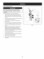
Thechutedean-outtool isconvenientlyfastenedto the rearofthe augerhousing
with amountingclip.Shouldsnowandicebecomelodgedin thechuteassembly
duringoperation,proceedasfollowsto safelycleanthe chuteassemblyandchute
opening:
Useextreme carewhen handling gasoline.Gasolineis extremely
flammable andthe vaporsareexplosive.Neverfuel the machineindoorsor
while the engine ishotor running. Extinguishcigarettes,cigars,pipes and
othersourcesof ignition.
1.
Release
boththe AugerControlandthe DriveControl.
2.
Stopthe enginebyremovingthe ignitionkey.
3.
Removethe clean-outtool from the clipwhichsecures
it to the rearof the
augerhousing.
4.
Usetheshovel-shaped
endof the clean-outtool to dislodgeandscoopany
snowandicewhichhasformedinandnearthe chuteassembly.
5.
Refasten
the clean-outtool to the mountingdip on the rearof the auger
housing,reinsertthe ignitionkeyandstartthe snowthrower'sengine.
6.
Whilestandinginthe operator'sposition(behindthe snowthrower),engage
the augercontrolforafewsecondstoclearanyremainingsnowandicefrom
the chuteassembly.
1.
Cleanaroundfuelfill beforeremovingcapto fuel.
2.
Afuel levelindicatoris locatedinthe fuel tank.SeeFigure15inset.Be
carefulnotto overfill.Filltank until fuel reachesthe fuellevelindicatorto
allowspacefor fuelexpansion.
Starting The Engine
Alwayskeephandsandfeet clearof moving parts. Donot usea pressurized
starting fluid. Vaporsareflammable.
flOTE:Allowthe engineto warmupfor afewminutesafter starting.Theenginewill
not developfull poweruntil it reachesoperatingtemperatures.
BeforeStarting Engine
Read,understand,andfollow all instructionsandwarnings onthe
machineandin this manualbeforeoperating.
1.
Makecertainboththe augercontrolanddrivecontrolarein thedisengaged
(released)
position.
2.
Insertkeyinto slot.Makesureit snapsinto place.Donot attemptto turn the
key.
NOTE:Theenginecannotstartwithoutthe keyfully insertedinto the
ignitionswitch.
Oil
Theunit wasshippedwith oil inthe engine.Checkoil levelbeforeeachoperationto
ensureadequateoil in the engine.
ElectricStarter
flO?E:Besureto checkthe engineonalevelsurfacewith the enginestopped.
1.
Removethe oil filler cap/dipstickandwipethe dipstickclean.
2.
Insertthe cap/dipstickinto the oil filler neck,but do NOTscrewit in.
3.
Removethe oil filler cap/dipstick.Ifthe levelislow,slowlyaddoil (5W-30,
with aminimumclassification
of SF/SG)
until oil levelregistersbetweenhigh
(H)andlow (L).
Theelectric starter isequippedwith a groundedthree-wire power plug,
andisdesignedto operate on 120voltAChouseholdcurrent. It must be
usedwith a properly groundedthree-prong receptacleat all times to avoid
the possibilityof electrk shock.Follow all instructions
carefully prior to
operatingthe electricstarter. DONOTuseelectric starter in the rain.
flOTE:Donot overfill.Overfillingwith oil mayresultin enginesmoking,hard
startingor sparkplug fouling.
Determinethatyourhome'swring isathree-wiregroundedsystem.Aska licensed
electricianif youarenot certain.
Replace
andtighten cap/dipstickfirmly beforestartingengine.
Ifyouhavea groundedthree-prongreceptacle,proceedasfollows.If youdonot
havethe properhousewiring, DONOTusethe electricstarterunderanyconditions.
4.
Gasoline
Useautomotivegasoline(unleadedor low leadedto minimizecombustionchamber
deposits)witha minimumof87 octane.Gasoline
with up to 10%ethanolor 15%
MTBE(MethylTertiaryButylEther)canbeused.Neveruseanoil/gasolinemixture
or dirty gasoline.Avoidgetting dirt, dust,or waterinthe fuel tank.DONOTuseE85
gasoline.
1.
Pluganextensioncordinto the outletlocatedon the engine'ssurface.Plug
the otherendofextensioncordintoathree-prong120-volt,grounded,AC
outlet inawell-ventilatedarea.
Theextensioncordcan beany length, but must be ratedfor 15ampsat
125volts,groundedand ratedfor outdoor use.
Refuelin awell-ventilatedareawith the enginestopped.Donot smokeor
allowflamesor sparksin the areawherethe engineisrefueledor where
gasolineisstored.
16
2.
ToEngageDrive
Movethrottle controlto FAST
(rabbit)_Jl__ position.
1.
With the
3 Move
choke
tothe
CHOKE
I,'I pos t on
eng
co,d
nestart),fengine
sthrottlecontrolinthe Fast(rabbit)_ _1
into oneof the sixforward(F)positionsor two reverse(R)positions.Selecta
speedappropriatefor thesnowconditionsanda paceyou'recomfortable
with.
warm,placechokein RUNposition.
4.
5.
Pushprimerthree(3)times,makingsureto covervent holeinprimerbulb
whenpushing.Ifengineiswarm,pushprimeronlyonce.Alwayscovervent
holewhenpushing.Coolweathermayrequireprimingto berepeated.
flOTE:Whenselectinga DriveSpeed,usetheslowerspeedsuntilyouare
comfortableandfamiliarwith theoperationof the snowthrower.
Pushstarterbuttonto startengine.Oncethe enginestarts,immediately
releasestarterbutton.Electricstarterisequippedwith thermaloverload
protection;systemwill temporarilyshut-downto allowstarterto coolif
electricstarterbecomes
overloaded.
2.
Squeezethe drivecontrolagainstthe handleandthe snowthrowerwill
move.Release
it anddrivemotionwill stop.
NOTE:NEVER
repositiontheshift lever(changespeedsor directionof travel)
without first releasingthe drivecontrolandbringingthesnowthrowerto a
completestop.Doingsowill resultin prematurewearto the snowthrower'sdrive
system.
Asthe enginewarms,slowlyrotatethe chokecontrolto RUNposition.Ifthe
enginefalters,restartengineandrunwith chokeat half-chokepositionfor a
shortperiodof time,andthenslowlyrotatethe chokeinto RUNposition.
6.
position,moveshift lever
Afterengineisrunning,disconnectextensioncordfrom electricstarter.
Whendisconnecting,
alwaysunplugthe endat the wall outletbefore
unpluggingthe oppositeendfromthe engine.
ToEngageAuger
Toengagetheaugerandstartthrowingsnow,squeezethe augercontrol
againstthe left handle.Release
to stopthe auger.
Recoil Starter
ReplacingShearPins
Eachaugerbladeissecuredto the spiralshaftwith ashearpinandbow-tieclip.If
anaugerbladestrikesa foreignobjector icejam, the pinwill shearoff to prevent
damageto the blade.Ifan augerbladedoesnot turn, checkto seeif its pinhas
shearedoff. SeeFigure16.
Donot pull the starter handlewhilethe engine running.
1.
Movethrottle controlto FAST
(rabbit)_ _j position.
2.
Movechoketo the CHOKE
I,*'1
position(coldenginestart).If engineis
warm,placechokein RUNposition.
3.
Pushprimerthree(3)times,makingsureto covervent holewhenpushing.
If engineiswarm,pushprimeronlyonce.Alwayscoverventholewhen
pushing.Coolweathermayrequireprimingto be repeated.
4.
Pullgentlyonthe starterhandleuntil it beginsto resist,then pullquickly
andforcefullyto overcome
the compression.
Donot releasethe handleand
allowit to snapback.ReturnropeSLOWLY
to originalposition.If required,
repeatthisstep.
5.
NEVER
replacethe augershear pinswith anything otherthan SearsSKU#
88389/0EMPart No.738-04124Areplacementshearpins.Any damageto
the augergearboxor other componentsasa result of failing to do sowill
NOTbe coveredbyyour snowthrower's warranty.
Alwaysturn off the snowthrower's engine and removethe keypriorto
replacingshearpins.
Asthe enginewarms,slowlyrotatethe chokecontrolto RUNposition.Ifthe
enginefalters,restartengineandrunwith chokeat half-chokepositionfor a
shortperiodof time,andthenslowlyrotatethe chokeinto RUNposition.
Toavoid unsupervisedengineoperation, never leavethe machine
unattended with the engine running. Turnthe engine off after useand
removekey.
Stopping TheEngine
Afteryouhavefinishedsnow-throwing,runenginefor afewminutesbefore
stoppingto helpdry offany moistureon the engine.
1.
Movethrottle controlto OFFposition.
2.
Removethe key.Removing
the keywill reducethe possibilityof
unauthorizedstartingof the enginewhileequipmentisnot inuse.Keepthe
keyina safeplace.Theenginecannotstartwithout the key.
3.
Wipeanymoistureawayfrom the controlson the engine.
J
17
Figure16
MAINTENANCE
SCHEDULE
Followthe maintenance
schedulegivenbelow.Thischartdescribes
service
guidelinesonly.Usethe ServiceLogcolumnto keeptrackofcompleted
maintenancetasks.Tolocatethe nearestSearsServiceCenteror to scheduleservice,
Beforeperformingany type of maintenance/service,disengageall controls
andstop the engine.Wait until all moving partshavecometo a complete
stop. Disconnect
sparkplug wire and groundit againstthe engine to
preventunintendedstarting.
simplycontactSearsat 1-800-4-MY-HOME
®.
1.
Engineoil level
1.
Check
2.
Looseor missinghardware
2.
Tightenor replace
3.
Unitandengine.
3.
Clean
Ist 5hours
1.
Engineoil
1.
Change
Annuallyor 25hours
1.
Sparkplug
1.
Check
2.
Controllinkagesandpivots
2.
Lubewith light oil
3.
Wheels
3.
Lubewith multipurposeautogrease
4.
GearshaftandAugershaft
4.
Lubewith light oil
5.
4-WayChuteControl
5.
Checkfor cableslackness
Annuallyor 50hours
1.
Engineoil
1.
Change
Annuallyor 100hours
1.
Sparkplug
1.
Change
BeforeStorage
1.
Fuelsystem
1.
Runengineuntil it stopsfrom lackoffuel
EachUseand every 5 hours
TM
f
EngineMaintenance
CheckingEngine Oil
Beforelubricating, repairing,or inspecting,
disengageall controlsandstop
engine.Wait until all movingparts havecometo acompletestop.
NOTE:Checkthe oil levelbeforeeachuseto besurecorrectoil levelismaintained.
Whenaddingoil to the engine,referto viscositychartbelow.Engineoil capacity
is600ml(approx.20oz.).Donot over-fill.Usea4-stroke,or anequivalenthigh
detergent,premiumquality motoroil certifiedto meetor exceedU.S.automobile
manufacturer'srequirementsforserviceclassificationSG,SF.Motoroilsclassified
SG,SFwill showthisdesignationon thecontainer.
1.
Removethe oil filler cap/dipstkkandwipethe dipstkk clean.
2.
Insertthe cap/dipstkkintothe oil filler neck,but do NOTscrewit in.
3.
Removethe oil filler cap/dipstick.Iflevelis low,slowlyaddoil until oil level
registersbetweenhigh(H)andlow (L).SeeFigure17.
4.
J
Figure17
Replace
andtighten cap/dipstickfirmly beforestartingengine.
Tip unitto drainoil intothe container.Usedoil mustbedisposedof at a
propercollectioncenter.
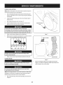
Changing EngineOil
NOTE:Change
the engineoil after the first 5 hoursof operationandoncea season
or every50 hoursthereafter.
1.
Drainfuel fromtank byrunningengineuntil the fueltank isempty.Besure
fuelfill capissecure.
2.
Placesuitableoil collectioncontainerunderoil drainplug.
3.
Removeoil drainplug.SeeFigure18on next page.
Usedoil isa hazardouswaste product. Dispose
of usedoil properly. Donot
discardwith householdwaste. Checkwithyour localauthorities or Sears
ServiceCenterfor safedisposal/recyclingfacilities.
5.
18
Reinstallthe drainplugandtighten it securely.
Refillwith the recommended
oil andcheckthe oil level.SeeRecommended
OilUsagechart.Theengine'soil capacityis20ounces.
(oF)-40o-20 o 0o 20o 40o
(oc)
Oil Drain
-30° -20° -10 ° 0°
Plug
\
DONOTuse nondetergentoil or 2-strokeengine oil. it couldshorten the
engine'sservicelife.
7.
Reinstallthe oil filler cap/dipsticksecurely.
Figure18
E
Thoroughlywashyour handswith soapandwater assoonaspossibleafter
handlingusedoil.
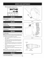
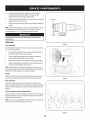
SparkPlug
CheckingSparkPlug
DONOTcheckfor sparkwith sparkplug removed.DONOTcrankenginewith
sparkplug removed.
Ifthe engine hasbeenrunning,the muffler will bevery hot. Becarefulnot
to touchthe muffler.
NOTE:Checkthe sparkplugonceaseasonor every25 hoursof operation.Change
the sparkplugonceaseasonor every100hours.Toensureproperengineoperation,
the sparkplug mustbeproperlygappedandfreeof deposits.
1.
Removethe sparkplugbootandusea sparkplugwrenchto removethe
plug.SeeFigure19.
2.
Visuallyinspectthe sparkplug.Discardthe sparkplugif thereisapparent
wear,or if the insulatoriscrackedor chipped.Cleanthe sparkplugwith a
wirebrushif it isto be reused.
3.
Measurethe pluggapwith afeelergauge.Correctasnecessary
bybending
sideelectrode.SeeFigure20.Thegapshouldbesetto .02-.03inches(0.600.80mm).
4.
Checkthatthe sparkplug washerisin goodconditionandthreadthe spark
plug inbyhandto preventcross-threading.
5.
Afterthe sparkplug isseated,tightenwith asparkplugwrenchto compress
the washer.
SparkPlugBoot
Figure19
Electrode
NOTE:Wheninstallinganewsparkplug,tighten 1/2-turnafterthe sparkplug
seatsto compressthe washer.Whenreinstallinga usedsparkplug,tighten 1/8- to
1/4-turnafter the sparkplugseatsto compressthewasher.
Thesparkplug mustbe tightened securely.Aloosesparkplug can become
very hot andcan damagethe engine.
Figure20
19
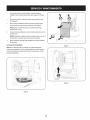
Lubrication
"I
GearShaft
Thegear(hex)shaftshouldbelubricatedat leastonceaseasonor after every25
hoursof operation.
I.
Topreventspillage,removeall fuel fromtank byrunningengineuntil it
stops.
2.
Carefullypivotthe snowthrowerupandforwardsothat it restsonthe auger
housing.
3.
Removethe lowerframecoverfrom the undersideof the snowthrowerby
removingthe self-tappingscrewswhichsecureit.
4.
Applya lightcoatingof engineoil (or3-in-1oil) to the hexshaft.SeeFigure
21.
NOTE:
Whenlubricatingthe hexshaft,becarefulnot to get anyoil onthe aluminum
driveplateor rubberfrictionwheel.Doingsowill hinderthe snowthrower'sdrive
system.Wipeoffany excessor spilledoil.
Wheels
J
Figure21
f
Atleastonceaseason,removebothwheels.Cleanandcoattheaxleswitha
multipurposeautomotivegreasebeforereinstallingwheels.
Auger Shaft
Atleastonceaseason,removethe shearpinson augershaft.Spraylubricantinside
shaft,andaroundthe spacers
andflangebearingsfoundat eitherendof the shaft.
SeeFigure22.
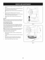
ShavePlate and Skid Shoes
Theshaveplateandskidshoeson the bottomofthe snowthroweraresubjectto
wear.Theyshouldbecheckedperiodkallyandreplacedwhennecessary.
flOT£:Theskidshoeson thismachinehavetwo wearedges.Whenonesidewears
out,theycanberotated180°to usethe otheredge.
Toremoveskidshoes:
Remove
thetwocarriage
bolts,washers,
andhexflangenutsthatsecure
eachskidshoetothesnowthrower.
2.
Reassemble
newskidshoeswith the fourcarriagebolts(two on eachside),
washers,andhexflangenuts.Referto Figure23.
f
Toremoveshaveplate:
1.
Removethe carriageboltsandhexnutswhichattachit to the snowthrower
housing.
2.
Reassemble
newshaveplate,makingsureheadsof carriageboltsareto the
insideof housing.Tightensecurely.SeeFigure23.
NOTE:Augersnot shown for clarity.
Figure 23
20
f
Adjustments
Shift Cable
If the full rangeof speeds(forwardandreverse)cannotbeachieved,referto the
figureto the fight andadjusttheshift cableasfollows:
I.
Placethe shift leverinthe fastestforwardspeedposition(F6).
2.
Loosenthe hex nut onthe shift cableindexbracket.SeeFigure24.
3.
Pivotthe bracketdownwardtotake upslackinthe cable.
4.
Retightenthe hexnut.
Drive Control
Whenthe drivecontrolis releasedandinthe disengaged
"up" position,the cable
shouldhaveverylittle slack.ItshouldNOTbetight. Also,if thereisexcessive
slack
inthe drivecableor if the unit experiences
intermittentdrivewhileusing,the cable
mayneedto beadjusted.Checkthe adjustmentof the drivecontrolasfollows:
I.
With thedrivecontrolreleased,pushthe snowthrowergentlyforward.The
unit shouldroll freely.
2.
Engagethe drivecontrolandgentlyattemptto pushthe snowthrower
forward.Thewheelsshouldnot turn. Theunit shouldnot roll freely.
3.
With thedrivecontrolreleased,movethe shift leverbackandforth between
Figure24
the R2positionandthe F6positionseveraltimes.Thereshouldbeno
resistanceinthe shift lever.
4.
If anyof the abovetestsfailed,the drivecableisinneedof adjustment.
Proceedasfollows:
a.
Shutoff the engineasinstructedinthe Operationsection.
b.
Loosenthe lowerhexbolt onthe drivecablebracket.SeeFigure25.
c.
Positionthe bracketupwardto providemoreslack(ordownwardto
increasecabletension).
d.
Retightenthe lowerhexbolt.
ChuteControlRod
Toachievemorechutecontrolrodengagementinthe inputshaftunderthe handle
panel,the chutecontrolrodwill haveto beadjusted.Referto Figure26.
Figure25
Toadjustthisrod,proceedasfollows:
I.
Removethe cotterpin fromthe holeclosestto the chutecontrolheadon the
chutecontrolinput.
2.
Pullout the chutecontrolroduntilthe holeinit linesupwith the otherhole
inthe chutecontrolinput.
3.
"',,,%
Reinsertthe cotterpinthroughthisholeandthe chutecontrolrod.
............................/
/
/
/
Figure26
21
/
/
/
....
f
Auger
Control
Referto theAssemblysectionforinstructionson adjustingtheaugercontrolcable.
Skid Shoes
Referto theAssemblysectionforinstructionson adjustingtheskidshoes.
Belt Replacement
Auger Belt
Toremoveandreplaceyoursnowthrower'saugerbelt, proceedasfollows:
I.
Topreventspillage,removeall fuel fromtank byrunningengineuntil it
stops.
2.
Removethe plasticbelt coveronthe front of the enginebyremovingthetwo
self-tappingscrews.SeeFigure27.
3.
Rollthe augerbeltoffthe enginepulley.SeeFigure28.
4.
Carefullypivotthe snowthrowerupandforwardsothat it restsonthe auger
housing.
5.
Removethe framecoverfrom the undersideof the snowthrowerby
removingfourself-tappingscrewswhichsecureit. SeeFigure29.
J
Figure 27
J
Figure29
22
Loosenandremovethe shoulderscrewwhichactsasabelt keeper.Referto
Figure30.
Removethe belt fromaroundthe augerpulley,andslipthe belt betweenthe
supportbracketandtheaugerpulley.SeeFigure31.
NOTE:Engagingthe augercontrolwill easeremovalandreinstallationof the
belt.
8.
Reassemble
augerbeltbyfollowing instructionsinreverseorder.
NOTE:DoNOTforgetto reinstallthe shoulderscrewandreconnectthespring
to the frameafterinstallingareplacement
augerbelt.
Performthe AugerControltestoutlinedinthe Assemblysectionof this
manual.
Drive Belt
NOTE:Severalcomponentsmustberemovedandspecialtoolsarerequiredin order
to replacethe snowthrower'sdrivebelt. Contactthe nearestSearsParts& Repair
Centerto havethe drivebelt replaced.
J
FrictionWheel Inspection
Figure30
If the snowthrowerfailsto drivewith the drivecontrolengaged,andperforming
the DriveControlCableAdjustmentfailsto correctthe problem,the frictionwheel
mayneedto bereplaced.Examinethe frictionwheelrubberforsignsof wearor
crackingandreplacewheelifnecessary.
NOTE:Severalcomponentsmustberemovedandspecialtoolsarerequiredin order
to replacethissnowthrower'sfrictionwheel.Ifyourfrictionwheelneedsto be
replaced,contactthe nearestSearsParts& RepairCenter.
Toinspectthe frictionwheel,proceedasfollows:
1.
Allowthe engineto rununtil it isout of fuel. Donot attemptto pourfuel
fromthe engine.
2.
Carefullypivotthe snowthrowerupandforwardsothat it restson theauger
housing.
3.
Removethe framecoverfrom the undersideof the snowthrowerby
removingfourself-tappingscrewswhichsecureit. Referto Figure29.
4.
Examinethe frictionwheelforsignsof wearor cracking.
Figure31
23
If the snowthrowerwill not beusedfor 30daysor longer,or if it is theendof thesnowseasonwhenthe lastpossibilityof snowisgone,the equipmentneedsto bestored
properly.Followstorageinstructionsbelowto ensuretop performancefrom thesnowthrowerformanymoreyears.
PreparingEngine
PreparingSnowThrower
Enginesstoredover30daysneedto bedrainedof fuel to preventdeteriorationand
gumfromforminginfuel systemor on essentialcarburetorparts.If thegasolinein
yourenginedeterioratesduringstorage,youmayneedto havethe carburetor,and
otherfuel systemcomponents,servicedor replaced.
Whenstoringthe snowthrowerin anunventilatedor metalstorageshed,
careshouldbetakento rustproofthe equipment.Usinga lightoil or silicone,
coatthe equipment,especially
anychains,springs,bearingsandcables.
1.
Removeall fuel fromtank byrunningengineuntil it stops.Donot attemptto
pourfuelfrom the engine.
Followlubricationrecommendations.
2.
Changetheengineoil.
3.
Removesparkplugandpourapproximately1oz.(30ml) ofcleanengineoil
into the cylinder.Pullthe recoilstarterseveraltimesto distributetheoil, and
reinstallthe sparkplug.
4.
Cleandebrisfrom aroundengine,andunder,around,andbehindmuffler.
Applya lightfilm ofoil on anyareasthat aresusceptibleto rust.
Removeall dirt fromexteriorof engineandequipment.
Storeequipmentinaclean,dry area.
Inflatethe tiresto the maximumPSI.Referto tire sidewall.
Storeinaclean,dry andwell ventilatedareaawayfromanyappliancethat
operateswith aflameor pilot light,suchasa furnace,waterheater,or
clothesdryer.Avoidanyareawitha sparkproducingelectricmotor,or where
powertoolsareoperated.
Neverstore snowthrower with fuel in tank indoorsor in poorlyventilated
areas,where fuel fumes may reachan openflame, sparkor pilotlight ason
a furnace,water heater,clothesdryeror gasappliance.
If possible,avoidstorageareaswith high humidity.
Keepthe enginelevelinstorage.Tiltingcancausefuelor oil leakage.
24
25
Disconnect
the sparkplug wireandgroundit againstthe engine to prevent
unintendedstarting. Beforeperforminganytypeof maintenance/service,
disengageall controls andstop the engine.Wait until aHmovingparts
havecometo a completestop.Alwayswear safetyglassesduringoperation
or while performingany adjustmentsor repairs.
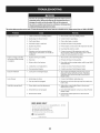
Thissection
addresses
minorservice
issues.
Tolocatethe nearestSearsServiceCenterorto schedule
service,
simplycontactSearsat 1-800-4-MY=HOMP.
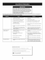
Engine fails to start
1. Choke control not in CHOKE position.
1. Move choke control to CHOKE position.
2. Spark plug wire disconnected.
2. Connectwire
3. Faulty spark plug.
3. Clean, adjust gap, or replace.
4. Fuel tank empty or stale fuel.
4. Fill tank with clean, fresh gasoline.
5. Engine not primed.
5. Prime engine as instructed
6. Key not inserted.
6. Insert key fully into the switch.
7. Extension
cord not connected
(when
Engine running
erratically/
RPM (hunting
1. Engine running
on CHOKE.
in the Operation
7. Connect one end of the extension
Section.
cord to the
electric starter outlet and the other end to a threeprong 120-volt, grounded, AC outlet.
using electric start button, on models so
equipped).
inconsistent
to spark plug.
1. Move choke control to RUN position.
2. Stale fuel.
2. Fill tank with clean, fresh gasoline.
3. Water or dirt in fuel system.
3. Drain fuel tank by running
with fresh fuel.
4. Carburetor
4.
or surging)
out of adjustment.
5. Over-governed
engine until it stops. Refill
Contact your Sears Parts & Repair Center.
5. Contact your Sears Parts & Repair Center.
engine.
Excessive vibration
1. Loose parts or damaged
Lossof power
1. Spark plug wire loose.
1.
2. Gas cap vent hole plugged.
2. Remove ice and snow from gas cap. Be certain vent
hole is clear.
1. Drive cable in need of adjustment.
1. Adjust drive control cable. Refer to Service and
Maintenance section.
2. Drive belt loose or damaged.
2. Have drive belt replaced. Contact your Sears Parts &
Repair Center.
3. Worn friction
3. Have friction wheel replaced at a Sears Parts &
Repair Center.
Unit fails to propel itself
1. Stop engine immediately
and disconnect spark
plug wire. Tighten all bolts and nuts. If vibration
continues, have unit serviced by a Sears Parts &
Repair Center.
auger.
wheel.
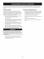
NEED MORE HELP?
Find this
and a[[ your
Get answers
from
other
our team
product
manuals
of home
experts.
online,
Get a personalized maintenance plan for your home.
Find information and tools to help Mth home projects.
26
Connect and tighten
spark plug wire.
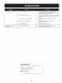
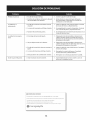
Unit fails to discharge snow
1. Chute assembly
clogged.
2. Foreign object lodged
Chute fails to easily rotate
180 degrees
1. Stop engine immediately and disconnect spark
plug wire. Clean chute assembly and inside of auger
housing with clean-out tool or a stick.
in auger.
2. Stop engine immediately and disconnect spark plug
wire. Remove object from auger with clean-out tool
or a stick.
3. Auger cable in need of adjustment.
3. Adjust auger control cable. Refer to Assembly
section.
4. Auger belt loose or damaged.
4. Replace auger belt. Refer to Service and
Maintenance section.
5. Shearpin(s) sheared.
5. Replace with new shear pin(s).
1. Chute assembled incorrectly.
1. Disassemble
directed
NEED MORE HELP?
YotJU,fir_} the _: swe a_] :m,_"
Yeo_:__._a_,a_emy[f_eo_@_,,,,,,,
fo_' free!
o Find this
and a[[ your
Get answers
from
other
our team
product
manuals
of home
experts,
online.
o Get a personalized maintenance plan for your home_
Find information
and tools to help with home projects.
27
chute control and reassemble
in the Assembly
section.
as
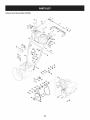
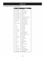
Craftsman SnowThrower Model 247.886914
20
15
54
31
10j_
i27
28
'
32
17
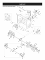
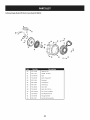
Craftsman SnowThrowerModel 247.886914
m
N
Snow Removal Tool Mount
28.
684-04264-4044
Housing
684-04057A-0637
Impeller
12" Dia.
29.
684-04107-0637
Spiral Assembly,
LH
710-0347
Hex Screw, 3/8-16, 1.75, Gr5
30.
684-04108-0637
Spiral Assembly,
RH
31.
731-04870
Spacer, 1.25 OD x .75 ID x 1.00
1.
731-2635
2.
3.
Assembly,
Assembly,
Auger 26"
4.
710-0451
Bolt, Carriage,
5.
710-04484
Screw, 5/16-18, 0.750
32.
736-0188
Washer, Flat, .76 x 1.49 x .06
6.
710-0703
Screw, Carriage,
33.
741-0493A
Bushing, Flange, .80 ID x .91 OD
790-00087A-0637
Housing,
5/16-18, .750 Grl
1/4-20, .750, Gr5
7.
712-04063
Nut, Flange Lock, 5/16-18, Nylon
34.
8.
712-04064
Nut, Flange Lock, 1/4-20, Nylon
35.
790-00121-4044
Shave Plate, 2.25 x 25.66
9.
712-04065
Nut, Flange Lock, 3/8-16, Nylon
36.
731-05984A
Slide Shoe
918-0123A
I" Hex Bearing
10.
714-04040
Cotter Pin, Bow-tie
37.
Housing,
Auger, RH Reduced
11.
936-0159
Washer, Flat, .349 x .879 x .063
38.
918-0124A
Housing,
Auger, LH Reduced
12.
926-04012
Nut, Push-on, .25 Dia
39.
921-0338
Seal, Oil, .750 x 1.00 x .125
13.
731-07525
Chute, Adapter
40.
741-0662
Bearing, Flange, .75 x 1.0 x .59
710-0642
Screw, Self-tapping,
5" Dia
14.
732-04460
Spring, Extension,
.38 OD x 4.59
41.
15.
736-0174
Washer, Wave, .625 x .885 x .015
42.
711-04284
Axle, Auger, 26"
16.
736-0242
Washer, Bell, .340 x .872 x .060
43.
914-0161
Key, Hi-pro 3/16 x 5/8
44.
715-04021
Pin, Dowel, .25 OD x 1.2
17.
946-04230A
Clutch
18.
931-2643
Snow Removal Tool
45.
917-04126
Shaft, Worm .75 OD
19.
738-0143
Screw, Shoulder,
.498 x .34, 3/8-16
46.
917-04861
Gear, Worm 20T
.625 x .17, 3/8-16
47.
718-04071
Collar, Thrust
721-0325
Plug, I/4 x .437
Cable, Auger, 47.23"
I/4-20,
20.
938-0281
21.
738-04124A
Shear Pin, .25 x 1.50
48.
22.
941-0245
Bearing, Hex Flange x .75 ID
49.
721-0327
Seal, Oil, .75 x I x .131
936-0351
Washer, Flat, .760 ID x 1.50D
Screw, Shoulder,
0.750
23.
941-0309
Bearing, Ball, .75 ID x 1.85 OD
50.
24.
756-04224
Flat Pulley, Idler, 2.75 OD
51.
736-3084
Washer, Flat, .51 x 1.12
25.
790-00075
Housing,
52.
741-0663
Bearing, Flange, .75 x 1.0 x .925
Bracket, Auger Idler w/Brake
53.
741-0661 B
Bearing, Flange, .75 x 1.00 x .975
Gearbox
54.
710-0276
Screw, Carriage, 5/16-18 x 1.00
26.
27.
790-00080A-0637
918-04172B
Bearing, 1.85 ID
Assembly,
Auger, 26"
29
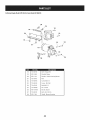
Craftsman SnowThrower Model247.886914
27
1
/
/
/
/
27
f
15
///
30
/
/
/
3O
28
29
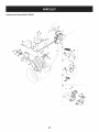
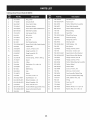
Craftsman SnowThrower Model 247.886914
1.
984-04338A
4-Way Chute Control
2.
710-04187
Hi-Lo Screw, 1/4-15 x 0.5
3.
715-0150
Roll Pin
4.
747-05116
Chute Rod
5.
710-04370
Hex Screw, 1/4-20 x 3.00
6.
738-04367
Flange Shoulder
7.
918-04801A
4-Way Chute Gearbox
8.
736-04446
Flat Washer, .25 x .630 x .0515
9.
920-0284
Wing
10.
936-0159
Flat Washer, .349 x .879 x .063
11.
731-04427A
Upper Chute
12.
914-0101
Cotter Pin
13.
711-04469A
Clevis Pin
14.
712-3087
Wing
15.
684- 0431 IA-0637
Chute Support
16.
714-04040
Bow Tie Cotter Pin
17.
712-04064
Flange Lock Nut, 1/4-20
18.
712-04063
Flange Lock Nut, 5/16-18
19.
784-5594-0637
Cable Bracket
20.
731-06451
Chute Tilt Cable Guide
21.
710-0262
Carriage
22.
710-0895
Hi-Lo Screw, 1/4-15 x .75
23.
710-04071
Carriage
24.
731-06440A
Lower Chute
25.
710-0627
Hex Screw, 5/16-24 x .750
26.
946-04528A
4-Way Cable
946-04477
4-Way Cable w/Clip
27.
753-06151
Handle Assembly
28.
731-04893A
Handle Plunger
29.
710-04879
Screw, Mach., #8-32 x .750
30.
710-04353
Screw, #8 x 1.00
31.
731-07031
Handle Lever
32.
984-04324A
Shift Assembly
33.
753-06152
Gear Set Assembly
34.
753-06153
Handle Housing
35.
710-1256
Screw, #8-18 x 1.250
36.
684-04350
Joint Block Assembly
3Z
715-04095
Pin
753-08018f
Chute Kit (Incl. Ref.# 11 & 24)
± Available
for warranty
service provider
coverage
Assembly
TM
Screw
Assembly
Knob
Nut, 1/4-20
Bracket
Bolt, 5/16-18 x 1.50
Bolt, 5/16-18 x 1.0
(Not Shown)
Assembly
only. Contact a Sears authorized
for details.
31
Craftsman SnowThrower Model247.886914
2
3
12
/
31
61/_
32
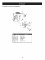
Craftsman SnowThrowerModel 247.886914
M
m
36.
732-0705
Cable Control
Torsion Spring
37.
749-04191A-0637
Upper Handle LH
Lock Plate
38.
710-04326
Screw, #8-16 x 0.50
684-04250
Pivot Rod
39.
732-04219C
Clutch Lock Spring
1.
684-04112C
Handle Engagement
2.
732-04238
3.
731-04894D
4.
Ass'y RH
Wire
5.
935-0199A
Rubber Bumper
40.
738-04126
Pin, 3/16
6.
710-3069
Screw, 1/4-20 x .500
41.
716-04036
Retainer
7.
731-04896B
Clutch
42.
936-0329
Lock Washer
8.
712-04081A
Shoulder
43.
710-1652
AB Screw, 1/4-20 x 0.625
44.
731-05353
Belt Cover
45.
926-04012
Push-on
Lock Cam
Nut, 1/4-20
Ring
9.
684- 04111 B
Handle Engagement
10.
631 -04133A
Handle Clutch
11.
720-0274
Handle Grip
46.
756- 04109
Auger Pulley
736-0505
Flat Washer
Assembly
LH
Lock LH Assembly
Nut
12.
710-1233
Screw, #10-24 x 0.375
47.
13.
738-04348
Shoulder
48.
738-04439
Shoulder
14.
710-04586
Screw, 1/4-20 x 1.625
49.
936-0119
Lock Washer
15.
749-04190A-0637
Upper Handle RH
50.
684-04169
Idler Pulley Assembly
16.
710-0572
Carriage
51.
790-00289A-0637
Pit., Cvr.
17.
720-04039
Shift Knob
52.
750-04571
Spacer
18.
753-06437
Handle Panel
53.
732-04308A
Torsion Spring
19.
731-05324
Lens
54.
710-0672
Hex Screw, 5/16-24 x 1.25
20.
731-06113
Steering
55.
756-04252
Pulley Half
21.
631-04134B
Handle Clutch
56.
954-04260
Belt, Wheel
710-0809
TT Screw, 1/4-20 x 1.25
Screw, 1/4-20
Screw, 5/16-18 x 2.25
Control
Lock RH Assembly
Screw
Drive
22.
725-0157
Ca ble Tie
57.
23.
712-04064
Flange Lock Nut, 1/4-20
58.
790-00208D
Drive Clutch Idler Bracket
24.
732-0193
Compression
59.
748-04112B
Shoulder
750-04477A
Spacer
Spring
Spacer
25.
790-00311B-0637
Shift Lever
60.
26.
790-00248C-0637
Panel Bracket
61.
710-0654A
TT Seres Screw, 3/8-16 x 1.0
27.
738-04125
Shoulder
62.
750-04303
Spacer
756- 04113
Pulley Half
Screw
28.
920-0284
Wing Knob
63.
29.
946-04396A
Speed Selector
64.
736-3082A
Flat Washer
30.
936-0267
Flat Washer
65.
710-0191
Hex Bolt, 3/8-24 x 1.25
31.
914-0145
Click Pin
66.
748-04053A
Pulley Adapter
32.
749-04138B-0637
Lower Handle
67.
710-1245B
Hex Bolt, 5/16-24 x 0.875
33.
710-04484
Screw, 5/16-18 x 0.75
68.
954-04050
V-Belt,.500
34.
710-04022
Screw, M8-1.25
N/A
35.
936-0264
Flat Washer, .330 x .630 x .0635
Cable
x 35.00 Lg
Engine (see breakdown)
MTD Model No. 952Z270-SUA
33
Craftsman SnowThrower Model247.886914
42
45
2
I
14 i
13
43
10
20
2O
36
22
26
45
24
I
28
57
62
58
56
59i
I
35
34
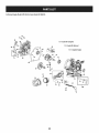
Craftsman SnowThrowerModel 247.886914
N
N
I.
735-04099
Plug, 3/8 ID
32.
738-04184A
Shoulder
2.
711-1268B
Actuator
33.
790-00316-4044
Frame Cover
3.
946-05067
Drive Clutch Cable
34.
656-04055
Friction
35.
918-06072
Drive Shaft Assembly
Shaft
Screw
Wheel
Disc Assembly
4.
732-04345
Extension
5.
790-00207C
Drive Clutch Cable Guide Bracket
36.
684-04153C
Friction
6.
684- 04156A
Shift Rod Assembly
37.
716-0136
Retainer
7.
750-04474
Axle Support
38.
726-0221
Speed Nut
8.
914-0126
Hi Pro Key
39.
790-00183C-4044
Wheel Drive Frame
9.
735-04100
Plug, 1/2 ID
40.
932-0264
Extension
10.
917-04210
Gear, 56T
41.
712-0417A
Flange Nut, 5/8-18
11.
941-0245
Hex Flange Bearing
42.
946-0956C
Steering Cable
12.
790-00206A-0637
Auger Clutch Cable Guide Bracket
43.
790-00528-4044
Shaft Retainer-
13.
756-0625
Cable Roller
44.
750-0767
Axle Spacer
712-04065
Flange Lock Nut, 3/8-16
Spring
Tube
Wheel Assembly
Ring
Spring
RH
14.
738-0924A
C Screw, 1/4-28 x 0.375
45.
15.
618-06988
Dogg Assembly
- LH
46.
710-0751
Hex Screw, 1/4-20 x .620
618-06987
Dogg Assembly
- RH
47.
790-00217A-0637
Speed Selector
Pivot Bracket
790-00218A-0637
Speed Selector
Shift Bracket
16.
936-3015
Washer, Flat
48.
17.
732-04311A
Torsion Spring, .750 ID x .968 Lg.
49.
712-04063
Flange Lock Nut, 5/16-18
18.
731-05297
Spacer
50.
712-04064
Flange Lock Nut, 1/4-20
618-0063A
19.
916-0104
E Ring
51.
Friction
Wheel
20.
736-0188
Flat Washer, .76 x 1.49 x .06
52.
935-04054
Friction
Wheel
21.
750-06087
Spacer
53.
790-00174C
Friction
Plate
22.
941-0563
Ball Bearing
54.
710-04484
Screw, 5/16-18 x .750
23.
938-04180
Axle
55.
710-1652
AB Screw, 1/4-20 x 0.625
24.
731-04873
Spacer
56.
918-06054
Gear Assembly,
25.
710-0788
TT Screw, 1/4-20 x 1.0
57.
918-06056
Carrier Assembly,
Shaft Retainer-
58.
711-06117
Shaft, Strbl Drv Hex, .812
26.
790-00527-4044
27.
634-04147A-091
634-04148A-0911
l
LH
Wheel Complete
- LH
59.
916-0231
E-Ring
Wheel Complete
- RH
60.
717-05146
Gear, Sun, 18T
717-1209A
Gear, 12T
Bearing Assembly
Plantry Ring
Plantry
Ring
28.
710-05339
Screw, 5/16-24 x 0.75
61.
29.
684-04154B-0637
Friction
62.
736-04581
Washer, Thrust, .75 x 1.25 x .03
30.
790-00096A-0637
Auger Cable Guide Bracket
63.
736-05031
Washer, Flat, .67 x 1.174 x .02
31.
748-0190
Spacer
Wheel Support
Brkt. Assy.
3S
Craftsman
EngineModel270-SUAForSnow Model247.886914
24
23
23
2
21
D -
19
951-11282
Muffler
Assembly
20
710-05001
Muffler
Stud
20
951-14190
Muffler
Stud Kit
21
951-11289
Muffler
Gasket
22
712-04214
Nut- M8
23
710-04915
Bolt-
24
951-I0642B
Muffler
M6 X 12 Zin
36
Shroud
o
ii
Craftsman EngineModel270-SUAForSnowModel 247.886914
41
_42
°0
37
35
D _
34
951-10634
Shroud-Engine
35
712-04213
Nut
36
951-11284
Choke Knob
37
951-10757
Throttle
39
951-10637
Switch-Ignition
4O
731-05632
Ignition
41
951-10640
Push Rod-Choke
42
951-10635
Air Filter Heating
43
710-04943
Bolt-M6
37
Knob
Key Switch
1X28M Spec
o
o
Craftsman
EngineModel270-SUAForSnow Model247.886914
7O
131-GasketKit-Complete
70-_%
70---_
132-GasketKit-External
133- CompleteEngine
63
62
38
Craftsman EngineModel270-SUAForSnowModel 247.886914
D -
o
0
50
951-12111
Piston Ring Set
51
951-11632
Piston Pin Snap Ring
52
951-12007
Piston
53
951-11633
Piston Pin
54
710-04915
Bolt- M6 X 12 Zin
55
951-11113
Shield - Air
56
951-11573
Connecting
57
951-14053
Governor
58
736-04461
Washer
59
951-11902
Governor
60
714-04078
Cotter Pin
61
951-11575
Camshaft
62
951-11369
Bearing
63
951-10307
Key:Flywheel
64
951-11247A
Crankshaft
65
951-11576
Governor
66
715-04092
Pin-Dowel
67
715-04096
Dowl Pin 9X14
68
951-11371
Crankcase Cover Gasket
69
951-12125
Crankcase Cover
Rod Assembly
Shaft
Seal
Assembly
Kit (Incl. 62,63,64,74,79)
Gear/Shaft
951-11246
Crankcase Cover Kit (Incl. 62,68-74)
70
710-04932
Bolt
71
951-11283
Oil Fill Plug Assembly
73
951-11577
O-Ring 15.8 X2.5
74
951-11368
Oil Seal
75
951-11249
Crankcase Kit (Incl. 59,62,74,75,79)
951-11060B
Shortblock
Assembly
(Incl. 4,21,27-29,44,46,
76
951-11350
Oil Drain Pipe
77
736-04440
Washer
78
710-04906
Bolt- Drain Plug
79
951-11370
Oil Seal
130
951-10641
Oil Drain Assembly
131
951-11059A
Gasket Kit-Complete
47, 50-53,56-79)
(Incl. 4,21,27-29,32,44,58,59,68,74,77,79)
132
951-10661B
Gasket Kit-External
133
952Z270-SUA
Complete
39
Engine
(Incl. 4,21,27 29,32,77)
Craftsman
EngineModel270-SUAForSnow Model247.886914
18
44
_
_p
49
U"
-"45
129
17
131-GasketKit-Complete
132-Gasket
Kit-External
133- CompleteEngine
40
46 _46
Craftsman EngineModel270-SUAForSnowModel 247.886914
ID -
o
0
1
710-04968
Flange Bolt M6
2
951-11054A
Valve Cover
3a
731-07059
Hose-Breather
3b
726-04101
Clamp-Breather
4
951-11565
Valve Cover Gasket
5
951-12000
Intake Valve Spring
6
951-11892
Rocker Arm Assembly
7
751-11124
Nut - Pivot Lockin
8
751-11123
Nut - Valve Adjust
9
951-11893
Rocker Arm
10
710-04902
Bolt - Pivot
11
951-12002
Exhaust Valve Adjuster
12
951-12003
Exhaust Valve Spring Retainer
13
951-12004
Valve Spring
14
951-11894
Intake Valve Seal
15
710-04933
Bolt - M8 X 55 Zin
16
951-11895
Push Rod Guide
17
951-10722B
Cylinder
18
951-10292
Plug:Spark
44
951-11572
Gasket-Cylinder
45
951-10648
Kit-Push Rod
46
951-11899
Tappet
47
715-04108
Pin-Dow110
48
951-10647A
Valve Kit
49
951-10647A
Valve Kit
129
951-12626
Valve Cover Kit
131
951-11059A
Gasket Kit-Complete
Hose
Retainer
Head Assembly
(Incl. 4-14,16,17,21,27-29, 44,48,49)
Head
X 16
(Incl. 4,21,27-29,32,44,58,59,68,74,77,79)
132
951-10661B
Gasket Kit-External
133
952Z270-SUA
Complete
41
Engine
(Incl. 4,21,27 29,32,77)
Craftsman
EngineModel270-SUAForSnow Model247.886914
134-Carburetor
Kit
-Deni
d\
e_
135-Carburetor
Kit
-Huayi
27
28
w
42
Craftsman EngineModel270-SUAForSnowModel 247.886914
II _
o
w
25
710-04939
Stud-Carb
26
710-04910
Stud-
27
951-11567
Gasket-Carb
28
951-11896
Carburetor
Insulat
29
951-11569A
Carburetor
Gasket
30
951-10639A
Primer
30
951-11824
Primer Bulb
31
951-14026A
Carburetor
Assembly
- Huayi
31
951-14027A
Carburetor
Assembly
- Deni
32
951-11897
Carburetor
Gasket
33
951-11112
Bracket-
134
951-14154
Carburetor
135
951-12788A
a
n/a
Choke Shaft
b
n/a
Choke Plate
C
n/a
Throttle
Shaft
d
n/a
Throttle
Plate
e
710-05469
Screw M3x5
f
736-04638
LockWasher
g
n/a
Gasket, Throttle
h
n/a
Idle Jet Assembly
I
n/a
Idle Speed Adjusting
J
n/a
Mixture
k
951-11699
Primer Hose
I
951-11906
Hose Clamp
m
n/a
Carburetor
n
n/a
Float Pin
o
n/a
Emulsion
P
951-12875
Float Needle Valve
q
n/a
Main Jet
r
n/a
Needle Valve Spring
s
n/a
Float
t
951-11589
Fuel Bowl Gasket
U
n/a
Fuel Bowl
V
951-11348
Fuel Bowl Gasket
W
710-04945
Fuel Bowl Mounting
X
951-11349
Fuel Drain Plug Gasket
Y
710-04938
Fuel Drain Plug
M6X 105
Insulator
Choke Control
Kit- Deni
(Incl. h,n,o,p,q,r,s,t,u,x)
Carburetor
Kit- Huayi
(Incl. h,n,o,p,q,r,s,t,u,x)
43
Plate
Screw
Screw
Body
Tube
Bolt
Craftsman
EngineModel270-SUAForSnow Model247.886914
82
86
84
92
85
D -
®
8O
951-10646
Ignition
81
951-11110
Shield - Air Flow
82
710-04940
Bolt
83
710-04919
Bolt - Flange M6
84
951-12416
Flywheel
85
951-10934
Cooling
86
951-10911
Starter Cup
87
712-04209
Nut- M14
88
710-04915
Bolt- M6X 12 Zin
9O
951-10663A
Fan Cover Complete
91
736-04455
Flat Washer-Recoil
92
710-04974
Flange Bolt M6
93
951-14151
Recoil Start Assembly
44
Coil
Fan
®
Craftsman EngineModel270-SUAForSnowModel 247.886914
,114
115
104
94
105
D
-
o
o
D
-
o
107
951-11914
Engine/Dipstick
Bolt-M6 X 12
108
710-04905
Bolt
Shield - Governor
109
710-04915
Bolt-
Governor
110
951-11913
Oil Fill Tube Assembly
111
951-11381
O-Ring
Rod-Governor
112
951-10656
Dipstick
113
951-11904
O-Ring Dipstick
114
951-12482
Dipstick
94
951-10758
Throttle
95
710-05103
96
951-I 1108
97
951-I 1935
98
951-10664
Spring-Throttle
99
951-I0665
Control
Assembly
Spring
Return
Governor
Cover
M6 X 12 Zin
Tube
101
951 -l I 106
Bracket-
102
712-04212
Nut-
103
710-04908
Bolt - M6 X 21 Gov
115
951-12533
Fuel Cap
951-11933
Fuel Level Indicator
951-10653B
Fuel Tank
M6
104
951-I1700
Hose Clamp-Carb
116
105
951-I0650
Kit-Fuel Line
117
106
710-04915
Bolt - M6 X 12 Zin
45
Assy
Craftsman
EngineModel270-SUAForSnow Model247.886914
118
119
120
123
121
121
124
m
D -
o
118
710-04914
Bolt- Flange M6
119
951-11680
Flexible Clamp
120
951-11114
Bracket-
121
712-05015
Nut
122
710-04965
Screw M4 X 55
123
710-04935
Screw - M4 X 60
124
710-05182
Bolt-M6 X 32
125
715-04088
Pin - Dowel
126
951-I0645A
Electric Starter
127
710-04915
Bolt- M6X 12 Zin
128
951-11109
Shield - Blower Housing
46
Switch Housing
e
Mount
Craftsman SnowThrower ModeJ247.886914
777S32636
777D16339
1001 lflO'NV]10
7VflNVW S,UO/VU3dO QV3U "_
"S]OV_flS 1]AVH9 NO9NILVU]dO
N_HM NOIlflYOVHJX__Sfl "SH30NV/S181¥ 39UVHOSIO
IO3UIQ8_A3N 'S31UflrNI S/O3rSO NMOHH/OIOAV 01 "_
"3NIHOVW 9NIOIAU3S HO 9NIgOOIONfl
3UOd38 Oqdd01S 3AVH SlUVd 9NIAOW llV llLNfl S]IQNVH
ONIH38 NIVW39 ONV'3NIgN3 dOiS '$83A31 HOLfllO 39VON3SIO"8
'31flHO 30UVHOSIO 9010Nil 01 1001 IflO'NV310
3Sfl "_
'L33_ ONV SONVH3LVLIIdlI_V NVOU3OflV UOU]ll3dWI HLIM
LOV±NO0"U]gflV ONY93113dWI ONllVLOU WOH_ IVMV d33H "L
777S32236
777122339
777D16338
STARTING
INSTRUCTIONS:
777D18152
777122363
777D16340
777X43688
777122340
CONTAINING
MOREi
THAN10% ETHANOL
'W
777D18045
47
FEDERAL
and/or CALIFORNIA
EMISSIONCONTROL
WARRANTYSTATEMENT
YOURWARRANTYRIGHTSANDOBLIGATIONS
MTD Consumer Group Inc, the United States Environmental
Protection Agency (EPA), and for those products
California, the California Air Resources Board (CARB) are pleased to explain the emission (evaporative and/or
warranty
on your 2013 and later small off-road
spark-ignited
engine and equipment
(outdoor
equipment
engines
must be designed,
built and equipped
to meet the State's stringent
equipment
engines
must be designed,
built, and equipped
to meet the U.S. EPA small off-road
equipment
anti-smog
certified
exhaust)
engine).
standards
engine
diagnosis,
condition
exists, MTD Consumer
Group Inc will repair your outdoor
equipment
new outdoor
regulations).
of time listed below, provided
Your ECS may include parts such as the carburetor, fuel-injection
system, ignition system, catalytic converter,
valves, canisters, filters, vapor hoses, clamps, connectors,
and other associated emission-related
components.
Where a warrantable
In California,
(in other states, outdoor
spark ignition
Consumer Group Inc must warrant the ECSon your outdoor equipment
engine for the period
abuse, neglect, or improper maintenance
of the outdoor equipment
engine.
for sale in the state of
control system (ECS)
MTD
there has been no
fuel tanks, fuel lines, fuel caps,
engine at no cost to you including
parts, and labor.
MANUFACTURER'S
WARRANTYCOVERAGE:
This emission
control system is warranted
for two years. If any emission-related
part on your outdoor
part will be repaired or replaced by MTD Consumer Group Inc. In the event that a component
Manufacturer's
equipment warranty, the longer coverage period will apply.
equipment
is covered
engine
for longer
is defective,
the
than two years by the
/
OWNERSWARRANTY
RESPONSIBILITIES:
As the outdoor equipment
engine
Consumer Group Inc recommends
Group Inc cannot deny warranty
As the outdoor
your outdoor
equipment
equipment
owner, you are responsible
that you retain all receipts
for performance
of the required maintenance
listed in your owner's manual. MTD
covering maintenance
on your outdoor equipment
engine, but MTD Consumer
solely for the lack of receipts.
engine
owner, you should
however
be aware that MTD Consumer
engine or a part has failed due to abuse, neglect,
improper
Group Inc may deny you warranty
maintenance,
or unapproved
coverage
if
modifications.
You are responsible for presenting your outdoor equipment
engine to MTD Consumer Group Inc's distribution
center or service center as soon
as the problem exists. The warranty repairs should be completed
in a reasonable amount of time, not to exceed 30 days. If you have a question
regarding
http://su
your warranty
pport.mtd
coverage,
you should contact
the MTD Consumer
Group Inc Service Department
at 1-800-800-7310
or at
prod ucts.com.
GENERALEMISSIONS
WARRANTYCOVERAGE:
MTD Consumer
designed,
Group Inc warrants
built, and equipped
cause the failure of a warranted
The warranty
period
Subject to certain
1.
to the ultimate
so as to conform
part for a period
Any warranted
and exclusions
regulations;
equipment
Group Inc according
remainder
of the period.
for replacement
to subsection
as required
Any warranted
part that is scheduled
stated above. Any such part repaired
only for regular inspection
or replaced under warranty
3.
Any warranted
for replacement
part that is scheduled
replacement
as required
to an ultimate
maintenance
(4) below. Any such part repaired
2.
of time before the first scheduled
that the outdoor
on emission-related
stated above. If the part fails during the period of warranty
Consumer
period
purchaser
and (2) free from defects
engine is delivered
as stated below, the warranty
part that is not scheduled
period
and each subsequent
equipment
in materials
engine
is: (1)
and workmanship
purchaser
or first placed into service.
parts is as follows:
in the written
coverage,
instructions
supplied
the part will be repaired
or replaced
under warranty
is warranted
or replaced
will be warranted
for the
in the written instructions
supplied is warranted for the warranty
will be warranted for the remaining warranty period.
maintenance
in the written
instructions
supplied
date for that part. If the part fails before the first scheduled
Repair or replacement
to the owner.
5.
Notwithstanding
of any warranted
the provisions
service the subject engines
6.
The outdoor
equipment
emission-related
7.
MTD Consumer
warranty
8.
Throughout
warranted
9.
herein, warranty
part, provided
the off-road
herein must be performed
services or repairs will be provided
for diagnostic
that such diagnostic
Group Inc is liable for damages
parts sufficient
provisions
is warranted
replacement,
at a warranty
at all of our distribution
period
station
for the
the part
under
at no charge
centers that are franchised
or equipment.
engine owner will not be charged
warranted
of any warranted
Any replacement
part under the warranty
for
by MTD
will be repaired or replaced by MTD Consumer Group Inc according to subsection (4) below. Any such part repaired or replaced
warranty will be warranted for the remainder of the period prior to the first scheduled replacement
point for the part.
4.
that
of two years.
begins on the date the outdoor
conditions
the warranty
purchaser
with all applicable
to other engine
labor that is directly
work is performed
or equipment
associated
at a warranty
components
with diagnosis
of a defective,
station.
proximately
caused by a failure under
part.
engine
and equipment
warranty
to meet the expected
demand
part may be used in the performance
the owner. Such use will not reduce the warranty
period
stated above, MTD Consumer
Group Inc will maintain
a supply of
for such parts.
of any warranty
obligations
maintenance
of MTD Consumer
or repairs and must be provided
Group Inc.
without
charge to
to
10. Add-on
ormodified
partsthatarenotexempted
bytheAirResources
Board
maynotbeused.
Theuseofanynon-exempted
add-on
or
modified
partsbytheultimate
purchaser
willbegrounds
fordisallowing
awarranty
claims.
MTDConsumer
Group
Incwillnotbeliable
to
warrant
failures
ofwarranted
partscaused
bytheuseofanon-exempted
add-on
ormodified
part.
WARRANTED
PARTS:
The repair or replacement
of any warranted
part otherwise eligible for warranty coverage may be excluded from such warranty coverage if
MTD Consumer Group Inc demonstrates
that the outdoor equipment
engine has been abused, neglected, or improperly
maintained, and that
such abuse, neglect,
any adjustment
coverage.
Further, the coverage
The following
1.
or improper
of a component
emission
Fuel Metering
warranty
maintenance
was the direct cause of the need for repair or replacement
that has a factory
under this warranty
parts are covered
installed,
extends
and properly
operating,
adjustment
limiting
of the part. That notwithstanding,
device is still eligible
only to parts that were present on the off-road
for warranty
engine and equipment
purchased.
(if applicable):
System
Cold start enrichment
Carburetor
system (soft choke)
and internal
parts (or fuel injection
system)
Fuel pump
Fuel tank
2.
Air Induction
System
Air cleaner
Intake manifold
3.
Ignition
System
Spark plug(s)
Magneto
4.
ignition
system
Exhaust System
Catalytic
converter
SAI (Reed valve)
5.
Miscellaneous
Items Used in Above System
Vacuum, temperature,
Connectors
6.
Evaporative
position,
time sensitive valves and switches
and assemblies
Control
Fuel hose
Fuel hose clamps
Tethered
Carbon
fuel cap
canister
Vapor lines
050790 Rev.A
Congratulations
onmakingasmartpurchase.
YournewCraftsman
®productisdesignedandmanufacturedfor yearsof
dependableoperation.Butlikeall products,it mayrequirerepairfromtime to time.That'swhenhavinga RepairProtection
Agreementcansaveyoumoneyandaggravation.
Here'swhat the Repair ProtectionAgreement_ includes:
[] Expertservice byour 10,000
professional
repairspecialists
[] Unlimitedservice and nocharge for partsandlaboronallcoveredrepairs
[] Productreplacementupto $1500if yourcoveredproductcan'tbefixed
[] Discountof 25%from regularpriceof serviceandrelatedinstalled
partsnot coveredbythe agreement;also,25%off
regularpriceof preventivemaintenance
check
[] Fasthelp by phone- wecallit RapidResolution- phonesupportfromaSearsrepresentative.
Thinkof usasa"talking
owner'smanual."
Onceyoupurchasethe RepairProtectionAgreement,a simplephonecallisallthat it takesfor youto scheduleservice.You
cancallanytimedayor night,or scheduleaserviceappointmentonline.
TheRepairProtectionAgreementisa risk-freepurchase.If youcancelfor anyreasonduringthe productwarrantyperiod,
wewill provideafull refund.Or,a proratedrefundanytimeafterthe productwarrantyperiodexpires.Purchase
yourRepair
ProtectionAgreementtoday!
Somelimitations and exclusionsapply. Forpricesand additional informationin the U.S.A.call 1-800-827-6655.
_Coveragein Canadavarieson someitems. Forfull details call SearsCanadaat 1-800-361-6665.
SearsInstallationService
ForSears
professional
installationof homeappliances,
garagedooropeners,waterheaters,andothermajorhomeitems,in
the U.S.A.or Canada
call1-800-4-MY-HOME
®.
5O
Declarad6n
de garantia .......................
Pr_cticas operaci6n
Montaje
Operad6n
seguras ...................
......................................
....................................
Servido y Mantenimiento
.....................
P_gina 51
Almacenamiento
P_gina 52
Solucidn de problemas ........................
P_gina 74
P_gina 56
Acuerdo de proteccidn
P_gina 78
P_gina 62
Lista de piezas ................................
P_gina 66
Numero de servicio ..................
fuera de temporada
.........
para reparaciones ......
P_gina 73
P_gina 28
Cubierta posterior
GARANTIA
COMPLETA
CRAFTSMAN
PORDOSANOS
PORDOS
ANOS
a partirdelafechadela compra,esteproductoest_garantizado
pordefectosen losmateriales
y la manodeobra.
Losproductos
defectuosos
ser_nreparados
sincostoo reemplazados
sincostosila reparaci6n
noest_disponible.
GARANTIADEPORVIDALIMITADAADICIONAL
en la tolva de UPPERy LOWER
PARA
SIEMPRE
Y CUANDO
SEUTILIZA
porel propietariooriginaldespu_s
delsegundoahodesdela fechadecompra,el conducto
superioreinferiordeeste
quitanieves
est_ngarantizados
contracualquierdefectodematerialesomanode obradebeserverificadopor unproveedor
deservicioautorizadoSears.Con
el comprobante
decompra,ustedrecibir_unarampanuevadeformagratuita.Ustedesresponsable
porel costode lamanodeobradeinstalaci6n
y otros
gastosocasionados
paraverificareldefect&
Paraobtenerinformaci6nsobreelalcancedela garantiay solicitarla reparaci6n
o elreemplazo,
visiteel sitioWeb:www.craftsman.com
EstagarantiacubreI]NICAMENTE
losdefectosenlosmateriales
y enla manodeobra.EstagarantiaNOcubre:
Elementos
no renovables
quepuedendesgastarse
porel usonormal,duranteel plazodela garantia,incluyendoentreotros,lasbarrenas,
laspaletasde
lasbarrenas,
loscortadores
dedesplazamiento,
laszapatasantideslizantes,
la placaderaspado,lospasadores
decuchilla,la bujia,elfiltro deaire,las
correasy el filtro deaceite.
Servicios
de mantenimiento
est_ndar,
cambiosdeaceiteo afinaci6n.
Cambiodeneum_ticos
o reparaciones
porpinchaduras
conobjetosexternoscomoclavos,espinas,
toconeso vidrios.
Reemplazo
o reparaci6n
deneum_ticos
oruedascomoresultadodeldesgaste
normal,unaccidente,
o funcionamiento
o mantenimiento
incorrectos.
•
Reparaciones
requeridas
comoresultadodelusoinadecuado
porpartedeloperador,
incluyendoentreotrosel dahoocasionado
porobjetosque
impactanla m_quinay quetuercenelbastidor,el ejedela barrena,etc.,o debidoa queel motorrueacelerado
enexceso.
Reparaciones
necesarias
debidoa negligencia
deloperador,
incluyendoentreotros,dahosmec_nico
y el_ctricoocasionado
por
unalmacenamiento
noapropiado,
fallaporel usodeaceitedegradoy/o cantidadnoapropiados
o fallapornodarmantenimiento
al equipodeacuerdoconlasinstrucciones
contenidas
enel manualdeloperador.
Limpiezao reparaciones
delmotor(sistemadecombustible)
debidasa combustible
quesedeterminaest_contaminado
u oxidado(viejo).Engeneral,el
combustible
debeutilizarseenunperiodonomayorde30diasa partirdesuadquisici6n.
Eldeterioroy desgaste
normaldelosacabados
exteriores,
o reemplazodelaetiquetadelproducto.
Lapresentegarantiaseanulasiseutilizaesteproductoalgunavezparaprestarservicios
comerciales
o siseIoalquilaa otrapersona.
Estagarantiale otorgaderechos
legalesespecificos,
peroustedpodriagozardeotrosderechos
en raz6nde sulugarderesidencia.
SearsBrandsManagement
Corporation,
HoffmanEstates,
IL60179
Aceite del motor:
5W-30
Numero de modelo
Combustible:
Gasolina sin plomo
Numero de serie
Motor:
MTD
Fecha de compra
© Sears Brands, LLC
51
Registre el numero de modelo, numero de serie y fecha
de compra m_s arriba.
Lapresendade este simboloindica cluesetrata de instrucciones
importantes de seguridadquesedebenrespetarparaevitar poneren
peligro suseguridadpersonaly/o materialy lade otras personas.Leay siga
todaslasinstruccionesde este manualantesde poner enfundonamiento
esta m_iguina.Sino respetaestasinstrucdonespodriaprovocarJesiones
personales.Cuandoyeaeste simboJo,ipresteatend6n a laadvertencia!
PROPOSICION
Estam_iquinarue construida parasetoperadadeacuerdoconlasreglas
de seguridadcontenidaseneste manual.AI igual queconcualquiertipo
de equipo motorizado,un descuidoo error pot parte deJoperadorpuede
producir lesionesgraves.Estam_iquinaescapazde amputar manosy pies
y de arrojar objetoscon gran fuerza.Deno respetarlasinstrucdonesde
seguridadsiguientessepuedenproducir lesionesgraveso la muerte.
65 DE CALiFORNiA
Su responsabilidad--Restrinja
el usodeesta m_quina motorizada
alas personasquelean,comprendany respeten lasadvertendase
instrucdones
queaparecenen este manualy en la m_quina.
Elescapedel motor deeste producto,algunosde suscomponentesy
algunoscomponentesdel vehiculocontieneno liberan sustanciasquimicas
queelestado deCaliforniaconsideraquepuedenprodudr c_ncer,defectos
de nadmiento u otros problemasreproductivos.
iGUARDE
ESTAS
INSTRUCCIONES!
CAPACITACION
PREPARATlVOS
Lea,entienday cumplatodaslasinstrucciones
incluidasenlam_quinay en
losmanualesantesde montarlay utilizarla.Guardeestemanualenun lugar
seguroparaconsultasfuturasy peri6dicas,asicomoparasolicitarrepuestos.
Inspecdoneminuaosamenteel_ireadondeutilizar_iel equipo.Saquetodoslos
felpudos,peri6dicos,trineos,tablas,cablesy otrosobjetosextrafiosconlosque
podriatropezaro quepodrianserarrojadosporlabarrena/impulsor.
Leael Manualdel 0peradory sigatodaslasadvertencias
e instrucciones
de
seguridad.Elfracasode hacerasipuedecausarlaheridaseriaaloperadory/o
personaspresentes.
Panprotegerselosojosutilicesiempreanteojosoantiparrasde seguridad
mientrasoperalam_iquinaomientraslaajustaorepara.Losobjetos
arrojadosquerebotanpuedenproducirlesionesocularesgraves.
Familiaricese
contodosloscontrolesy conelusoadecuadodelosmismos.
Sepac6modetenerlam_quinay desactivarloscontrolesr_pidamente.
Nooperelam_iquinasinlavestimentaadecuada
paraestaral airelibreen
inviemo.Noutilicealhajas,bufandaslargasu otrasprendassueltasque
podrianenredarse
en laspartesm6viles.Utiliceun calzadoespecialpara
superficiesresbaladizas.
Nopermitanuncaquelosnifiosmenoresde 14afiosutilicenestam_quina.
Losnifiosde 14afiosen adelantedebenleery entenderlasinstrucciones
deoperaci6ny normasde seguridadcontenidasen estemanual,y enla
m_quinaydebenserentrenadosy supervisados
pot unadulto.
Useun prolongadory un tomacorrientedetrescablesconconexi6natierra
paratodaslasm_iquinas
conmotoresdeencendidoel_ctrico.
Nuncapermitaquelosadultosoperenestam_quinasinrecibirantesla
instrucci6napropiada.
Ajustelaalturade lacajadel tomacorrienteparalimpiarlagravao las
superficiesconpiedrastrituradas.
Losobjetosarrojadosporlam_quinapuedenproducirlesionesgraves.
Planifiqueel patr6nenelquevaair arrojandonieveparaevitarquela
descargade materialserealicehacialoscaminos,losobservadores,
etc.
Desengrane
todaslaspalancasdecontrolantesdearrancarel motor.
Nuncaintenterealizarajustesmientraselmotorest_ien marchaexceptoen
loscasosespecificamente
recomendados
enel manualdel operador.
Mantengaa losobservadores,
ayudantes,
mascotasy nifiosporIo menosa
75piesde lam_quinamientraslamismaest_enfuncionamiento.Detengala
m_quinasialguienseacerca.
Seaprecavidoparaevitarpatinarseo caerseespecialmente
cuandooperala
m_quinaenreversa.
52
Dejequeel motory lam_iquinaseadaptenalatemperaturaexteriorantes
decomenzara sacarlanieve.
Manejo
seguro de la gasolina
Paraevitarlesionespersonales
o dafiosmaterialestengamuchocuidadocuando
trabajecongasolina.Lagasolinaessumamenteinflamabley susvaporespueden
causarexplosiones.Sisederramagasolinaencimaosobrelaropasepuedelesionar
gravementeyaquesepuedeincendiar.L_veselapiely c_mbiesederopade
inmediato.
Nuncaoperelam_quinasifalta un montajedelcanalo s[elmlsmoest_
daffado.Mantengatodoslosdispositivosdeseguridadensulugaryen
funcionamiento.
Nuncaendendaelmotorenespadoscerrados
o enunazonaconpoca
ventilad6n.Elescapedelmotorcontienemon6xidode carbono,un gas
inodoroy letal.
Utilices61olosredpientesparagasolinaautorizados.
Noutilicelam_quinabajolainfluendadel alcoholo lasdrogas.
Apaguetodoslosdgarrillos,dgarros,pipasy otrasfuentesdecombusti6n.
Elsilendadory el motorsecalientany puedencausarquemaduras.Nolos
toque.Mantengaalosnifiosalejados.
Nuncacarguecombustibleen lam_quinaenun espadocerrado.
Seasumamenteprecavidocuandooperelam_quinasobreunasuperfide
congravaocuandolacruce.Mant_ngase
alertaporsisepresentanpeligros
ocultosotr_nsito.
Nuncasaquelatapadelcombustibleniagreguecombustiblemientrasel
motorest_calienteoen marcha.
Dejequeel motorseenfrieporIomenosdosminutosantesde volvera
cargarcombustible.
Tengacuidadocuandocambiededirecd6nocuandooperelam_quinaen
pendientes.Nouselam_quinaenpendientespronundadas.
NuncaIleneenexcesoeldep6sitodecombustible.Lleneeltanquea no m_s
de1/2pulgadapordebajode labasedel cuellodeIlenadodejandoespado
paraladilatad6ndel combustible.
Planifiqueelpatr6nenelquevaa irarrojandonieveparaevitarquela
descargade materialseproduzcahadalasventanas,lasparedes,los
autom6viles,etc.y evitarasiposiblesdafiosmaterialeso lesionesproduddas
porlosrebotes.
Vuelvaacolocarlatapadelagasolinay ajOstelabien.
Limpieelcombustiblequesehayaderramadosobreel motory elequipo.
Traslade
lam_quinaaotra zona.Espere5minutosantesde encenderel
motor.
Nuncadirija [adescargahadalosnifios,losobservadores
o lasmascotas
ni
dejequenadieseparedelantedelam_quina.
Nosobrecargue
lacapaddaddelam_quinatratandodesacarlanievemuy
r_pidamente.
Nuncaalmacenelam_quinao elredpientede combustibleenunespado
cerradodondehayafuego,cHspasoluzpiloto (porejemplo,hornos,
calentadores
deagua,calefactores,
secadores
de ropa,etc.).
Nuncaopereestam_quinasinbuenavisibilidadoiluminad6n.Siempredebe
estarsegurodequeest_bienafirmadoy sujetandofirmementelasmanijas.
Camine,nuncacorra.
Dejequelam_quinaseenfrie porIomenos5 minutosantesdeguardarla.
NuncaIlenelosredpientesen elinteriorde unvehkuloocami6no cajade
remolqueconrecuMmientospl_sticos.Coloquesiemprelosredpientesen el
pisoy lejosdelvehkuloantesdeIlenarlos.
Siesposible,retireelequipoa gasolinadelcami6noremolquey II_neloen
elsuelo.Siestonoesposible,Ileneel equipoenun remolqueconcontenedor
port_t[I,envezdedesdeunaboquilladispensadora
degasolina.
Cortelacorriente
alabarrena
/impulsorcuando
transporte
lam_quina
o
cuando
lamismanoest_enuso.
Nuncaoperelam_quinaaaltaveloddaddedesplazamiento
sobre
superficiesresbaladizas.
Mirehadaabajoy hadaatr_sy tengacuidado
cuandovayamarchaatr_s.
Si lam_quinacomenzaraavibrardemaneraanormal,detengaelmotor,
desconecteelcabledelabujiay p6ngalademaneraquehagamasacontra
el motor.Inspecdonelam_quinaminudosamenteparavet siest_dafiada.
Repare
todoslosdafiosantesdeencendery operarlam_quina.
Mantengalaboquilladispensadora
encontactoconelbordedeldep6sito
decombustibleoconlaaberturadel redpienteentodo momento,hasta
terminarlacarga.Noutilke undispositivodeapertura/derredeboquilla.
FUNCIONAMIENTO
Nopongalasmanoso lospiescercadelaspiezasrotatorias,enlacajadela
barrena/impulsor oenel montajedelcanalde descarga.
Hacercontactocon
piezasgiratoriaspuederesultaren laamputad6nde manoso pies.
Lapalancadecontrolde labarrena/impulsoresundispositivodeseguridad.
Nuncaevitesufundonamiento.Dehacerlolaoperad6nde lam_quinaes
riesgosay puedeocasionarlesiones.
Laspalancas
decontroldebenfundonarbienenambasdkecdonesy
regresarautom_ticamente
a laposid6nde desengrane
cuandoselassuelta.
Desengrane
todaslaspalancas
decontroly detengaelmotorantesdedejar
la poski6nde operad6n(detr_sde lasmanijas).Espere
a quelabarrena/
impulsorsedetengapotcompletoantesdedestaparelmontajedel canalo
realizarajusteseinspecdones.
Nuncapongalasmanosenlasaberturasdedescargao derecolecd6n.Utilke
siemprelaherramientadelimpiezaqueseadjuntaparadestaparlaabertura
de descarga.
Nodestapeelmontajedelcanalmientrasel motorest_en
fundonamiento.Antesdedestaparlo,apagueel motory permanezca
detr_s
de lasmanijashastaquetodaslaspartesm6vilessehayandetenido.
Uses61ounionesy accesorios
aprobadosporel fabricante(porejemplo,
pesasparalasruedas,cadenasparalosneum_ticos,
cabinas,etc.).Para
obtenerm_sinformad6nacercadeestostemas,Ilameal 1-800-469-4663.
53
Paraencenderel motor,jaiede lacuerdalentamentehastaquesienta
resistenda,luegojaler_pidamente.Elreplieguer_pidodelacuerdade
arranque(tensi6nde retroceso)
lejalar_la manoy elbrazohadaelmotor
m_sr_pidodeIoqueustedpuedesoltar.Elresultadopuedenserhuesos
rotos,fracturas,hematomaso esguinces.
SegunlaComisi6n
de SeguridaddeProductosparaelConsumidor
delos
EstadosUnidos(CPSC)
y laAgenciadeProtecci6nAmbientaldelosEstados
Unidos(EPA),esteproductotJeneunavidafitil mediade siete(7)afros,6
60 horasdefuncionamiento.AI finalizarlavidafitil media,adquierauna
m_quinanuevaohagainspeccionar
anualmente6staporundistribuidorde
servicioautorizadoparacerciorarse
dequetodoslossistemasmec_nicos
y de
seguridadfuncionancorrectamente
y notienenexcesivodesgaste.SinoIo
hate,puedenproducirseaccidentes,lesioneso muerte
Sisepresentansituaciones
quenoest_nprevistasenestemanual,sea
cuidadosoy useelsentidocomfin.
Parapedirrepuestososerviciohorarioparaesteproducto,Namea1-800469-4663.
MANTENIMIENTO
Nuncaalmacenelam_quinaoel recipientedecombustibleen unespacio
cerradodondehayafuego,chispaso luzpilotocomoporejemplo,
calentadoresdeagua,hornos,secadores
deropa,etc.
Y ALMACENAMIENTO
Nuncaalterelosdispositivos
de seguridad.Controleperi6dicamente
que
fundonencorrectamente.Remftase
alassecciones
demantenimientoy
ajustedeestemanual.
Consulte
siempreelmanualdeloperadorparaobtenerinstrucciones
adecuadas
paraelalmacenamiento
fueradetemporadaVerifique
frecuentementelaIfneade combustible,eltanque,eltap6n,y losaccesorios
buscandorajaduraso p6rdidas.Reemplace
desernecesario.
AntesdereaNzarlaNmpieza,repararo revisarlam_quina,desengrane
todaslaspalancas
decontroly detengaelmotor.Espere
a quelabarrena/
Nod6arranqueal motorsi noest_labujfadeencendido.
impulsorsedetengaporcompleto.Desconecte
elcabledelabujfay p6ngalo
EL MOTOR
haciendomasacontraelmotorparaevitarqueseenciendaaccidentalmente. NO MODIFIQUE
Paraevitarlesionesgraveso lamuerte,no modifiqueel motorbajoninguna
Controlefrecuentemente
quetodoslospernosy tornillosest#nbien
circunstancia.
SIcambialaconfiguraci6ndelreguladorelmotorpuede
ajustadosparacomprobarquelam_quinaseencuentraen condidones
descontrolarse
y operaravelocidades
inseguras.Nuncacambielaconfiguraci6nde
segurasdefuncionamiento.Adem_s,hagaunainspecci6nvisualdela
f_bricadel
regulador
d
elmotor.
m_quinaparaverificarsiest_dafrada.
AVlSO
Nocambielaconfigurad6ndel reguladordel motorniaceleredemasiado
elmismo.Elreguladordel motorcontrolalaveloddadm_ximasegurade
funcionamiento
del motor.
REFERIDO
A EMISIONES
Losmotoresqueest_ncertificadosy cumplenconlasregulaciones
deemisiones
federalesEPA
y de CaliforniaparaSORE
(Equipospequefrostodoterreno)est_n
certificadosparaoperarcongasoNna
comtinsinplomoy puedenincluirlos
siguientessistemasdecontrolde emisiones:
Modificaci6ndemotor(EM)y
catalizadordetresvfas(TWC)siest_nequipadosdeesamanera.
Lasplacasde raspadoy laszapatasantideslizantesqueseusanconla
m_quinaquitanievesedesgastany sedafran.Paraprotegersuseguridad,
verifiquefrecuentemente
todosloscomponentes
y reempl_celos
s61ocon
partesdelosfabricantesdeequiposoriginales(OEM).iEIusode piezasque
nocumplenconlasespeciflcadones
delequipooriginalpuederesultaren
rendimientoinadecuado
adem_sdeponerenriesgolaseguridad!
GUARDACHISPAS
Estam_quinaest_equipadacon un motor de combusti6ninternayno
debeset utilizadaen o cercade un terreno agrestecubierto potbosque,
maiezaso hierbaexceptosi el sistemade escapedel motorest_ equipado
conun amortiguador dechispasquecumpla conlasleyeslocaleso
estatalescorrespondientes,en casode haberlas.
Reviselaspalancasdecontrolperi6dicamente
paraverificarqueengraneny
desengranen
adecuadamente
y ajtistelossi esnecesario.Consultelasecd6n
deajustesde estemanualdeloperadorparaobtenerinstrucciones.
Mantengaoreemplacelasetiquetasdeseguridadeinstrucciones
segtinsea
necesario.
Siseutilizaun amortiguadorde chispaseloperadorIodebemanteneren
condiciones
de usoadecuadas.
Enel EstadodeCalifornialasmedidasanteriormente
Respetelasnormasreferentesaladisposici6ncorrectay las
reglamentaciones
sobregasolina,aceite,etc.paraprotegerel medio
ambiente.
mendonadassonexigidasporley(Artkulo 4442delC6digode Recursos
Ptiblicos
de California).Esposiblequeexistanleyessimilaresenotrosestados.Lasleyes
federalesseaplicanen territoriosfederales.
Antesdealmacenarlam_quinaenci@ndala
unosminutosparasacarlanieve
quehayaquedadoen lamismay paraevitarasfquesecongelelabarrena/
impulsor.
Puedeconseguirelamortiguadordechispasparael silendadora travdsdesu
distribuidorautorizadode motoreso ponidndoseencontactoconeldepartamento
de servicios.
54
S|MBOLOSDESEGURIDAD
Esta p_gina describe los simbolosy figuras de seguridad internacionales que pueden aparecer en este producto. Lea el manual del operador para obtener la
informaci6n terminada sobre seguridad, reunirse, operaci6n y mantenimiento
y reparad6n.
LEA EL MANUAL DEL OPERADOR (S)
Lea, entienda,y
siga todas las instrucciones
en el manual (es) antes de intentar
reunirse y funcionar.
LA ADVERTENCIA -- PLATOS ROTATORIOS
Guarde manos de entrada
girar platos dentro.
y aperturas
de la descarga mientras
la m_quina
corre. Alli ellos hacen para
LA ADVERTENCIA -- LAMINAS ROTATIVAS
Guarde manos de entrada
dentro.
y aperturas
de descarga mientras
la m_quina
corre. Alli hacen girar I_minas
LA ADVERTENCIA -- TALADRO ROTATIVO
No ponga manos o pies cerca del giro de partes, en el alojamiento
de taladro/aspa
tolva. Contacto con las partes rotativas puede amputar manos y pies.
OBJETOS LANZADOS
Esta m_quina
o asamblea
de
POR ADVERTENClA
puede recoger y lanzar objetos
que pueden
causar la herida personal
seria.
GASOLINA DE ADVERTENClA ESINFLAMABLE
Permita que el motor se enfrie al menos dos minutos
ADVERTENCIA
--
MONOXIDO
Nunca dirijas un motor dentro
contienen
el mon6xido
antes del reabastecimiento
DE CARBONO
o en un _rea mal ventilada.
de carbono,
de combustible.
un gas inodoro
Los gases de combusti6n
de motor
y mortal.
ADVERTENCIAELECTROCHOQUE
No use el juez de salida el_ctrico del motor en la Iluvia.
Suresp0nsabilidad-Restdngir
el us0de esta m_quinam0t0rizadaa laspersonasqueLean,c0mprendany
respetenlasadvertendase instrucd0nesde estemanualy en la m_quina.
ADVERTENCIA:
GUARDE
ESTAS
INSTRUCCIONES!
55
J
NOTA:
lasreferencias
al ladoderechoo y ciertosdelam_quinaquitanievese
determinandesdelaparteposteriordelaunidaden posici6nde operaci6n
(permaneciendo
directamentedetr_sdelam_quinaquitanieve,mirandohaciael
paneldelamanija).
4_
Extracd6n de ia Uaidadde ia Caja
I
1.
Cortelasesquinas
de lacajadecart6nyexti_ndalaenel pisoQuitey descarte
todoslosinsertos
deempaque.
2.
Saquelam_quinaquitanievedelacaja.
3.
Asegtirese
de vaciarcompletamentelacajaantesde tirarla.
Montaje
1.
Cabezalde
Control del
j,
/anal
M_nsnlade
Soportedel
_nal
Canal
Observe
el_reainferiortraserade lam_quinaquitanieveparaasegurarse
de
queamboscablesest_nalineadosconlasgu[asrotatoriasantesde girarla
manijahaciaarriba.
a.
Coloquela palancadecambiosenlaposid6ndeavarice(F)6.
b.
Tirehaciaarribay haciaatr_sdelamanijasuperior,tal y comose
muestraen laFigura1.Cuandoustedlevantaelmangohaciaarriba,
asegtirese
queambosfinalesdelcabledecentrosoncolocados
correctamente
enlossoportes.Alineelamanijasuperiorconla
manijainferior.
Basedel Mist
c.
\
Figura2
Aprietelasperillasmanualesquesujetanlamanijasuperiora la
manijainferior.Retirey descartetodoslasbandasde pl_stico,si Las
hubiera.Unicamenteseutilizanparaelempaque.
2.
Retireelpasadordechaveta,latuercade mariposay eltornillo hexagonal
delcabezaldecontroldelcanal,y elpasadorde horquillay elpasadorde
chavetaconuni6ncurvade lam_nsuladesoportedelcanal.Veala Figura2.
3.
Insertelavarillahexagonaldentrodelcabezaldecontroldelcanal.Empuje
lavarillatan lejosdentrodel cabezaldecontroldel canalcomoseaposible,
manteniendoelorificioen lavarillahexagonalseffalandohaciaarriba.Yea
laFigura3.
./s
I
J
Figura3
J
Figura1
56
4.
Ublque
el canalsobre
la base
delmlsmoygarantlzar
lavarillahexagonal
f
est_sltuadobajoelpanelmanejar.
Instalar
elpernohexagonal
prevlamente
ellminado,
peronoseguro
contuercademarlposa
enestemomento.Veala
Flgura
4.
5.
Aprlete
eldlsparador
enla palanca
decontrolygireel canalmanualmente
paraquemirehadadelante.
Losorifidosenelcabezal
decontroldelcanal
estar_n
mlrando
hadaarrlba.VealaFlgura
5.
CabezaI
de
Control
delCanal
NOTA:
Elcanalnogirar_sinquesehayaapretado
eldlsparador
enlapalanca
decontrol.
6,
Girelapalanca
decontrola launaposici6n
tanquelaflecha[ndicadora
plateada
enelengranaje
delplff6npordebajodelpaneldecontrolseffale
haclaarrlba.VealaFlgura
6.
NO@:Lapalanca
decontrolgirar_Ilgeramente
hacla
laderecha.
Veala
Flgura
5& laFlgura
6.
f
Fignra 5
f
Vista
Palancade
control Frontal
......................................
ii
.J
Figura4
J
Figura6
57
7.
InsertelavarJJia
hexagonaldentrode[engranajede[piff6npordebajode [a
paJanca
decontrol.AsegtiresedeaJJnear
elorificioen [avariJJa
hexagonal
con[aflechaenelengranajede[ pJffdn,Vea[aFigura7.
flOTA"
Elorifido esunareferendaparaaJinear[avariJJa
con[aflecha
indicadoraenelengranajede[ piffdn,
8.
Empujelavarillahaciael paneldecontrolhastaqueelorificJoen [avariJJa
hexagonalseaJineeconelorJfJdoen [aentradade controlde[canalIo m4s
cercaposibledelcabeza[decontrolde[canale inserteel pasadordechaveta.
VealaFigura8.
j
/
/
/
NO@:ElsegundoorifJciopuedeutilizarsem4stardeparareaJJzar
ajustessi
elcanalnogiratotalmente.Vealasecci6nde Servicioy Mantenimientopara
[oreferentea Ajustesde[aVarilJadeControlde[ Canal.
9.
Termineasegurandoelcabeza[decontrolde[ canala lam_nsuJa
desoporte
de[canalcon[atuercademariposay el pasadordehorquillay elpasadorde
chavetaconunidncurvaretiradosen elPaso2. VealaFigura9.
f
'x
i'
/
.J
Figura 8
F
Figura7
\
Figura9
58
Controlequetodosloscablesest@n
adecuadamente
dirigidosatrav@s
de la
guiadecablesenel motor.VealaFigura10.
NOTA:
Param_ssuavefuncionamiento,loscablesdebenestaralaizquierda
delavarillahexagonal.
Configurad6n
Pasadorde cuchilla
Enelpanelde instrumentos
de pl_sticohayorificiosparaelalmacenamiento
conveniente
del pasadordecuchilla.Yealafigura11. Consultelasecionde servkio
y mantenimientoparam_sinformacidn
en cuantoelreemplazodelpasadorde
cuchilla.
I
J
Figura10
f
J
Figura11
59
Herramienta de Limpieza del Canal
Hayuna herramientadelimpiezadelcanal iajustada
a lapartesuperiorde [acaja
de[abarrenaconun pasadordeensamNado.Vea[aFigura12.Laherramientaest_
diseffadapara[impiarelhieloy [anievedel montajede uncanal Esteproductose
sujetamedianteunauni6ndecaneen[af_brica.Corte[auni6ndecaneantesde
operar[am_quinaquitanieve.
Herramientade
Nuncausesusmanospara[iberar un montaje de canaltapado. Apague
e[ motor ypermanezca
detr,_sde [asmanijashastaquetodas[aspartes
m6viiessehayandetenido antesde utiiizar la herramientade limpieza
para[impiar e[ montaje de[ canal
Presi6nde losNeum_ticos
Bajoningunacircunstanciano excedandel fabricante recomiendapsi.
Laigualdadde la presi6nde losneum_tkos debenmantenerseen todo
momento.Cuandola presi6nexcesivapuedecausarasientosbolas
neum_ticoI llanta de montaje parareventarcon lafuerzasuficiente para
causarun daffo grave.Serefieren a losflancosde losneum_tkos de la
presi6nrecomendada.
••/•i
........
_y
Figura12
Losneum_ticossondemasiadoinflados
paraprop6sitosdeenv[o.Reviselapresi6n
delosneum_ticosantesdelanievelanzador.Serefierena laparedlateraldel
neum_ticoparael fabrkantedeneum_ticosrecomendado
psiy desinflar(o inflar)
losneum_ticos,
segunseanecesario.
/
/
/
Superfkielisa
NO@:Laigualdadde lapresi6ndelosneum_ticosdebesermantenidaentodo
momentoparalosefectosde laperformance.
Ajustes
Zapatasantideslizantes
Laszapatasantideslizantes
dela m_quinaquitanieveseajustanparaarribaen
f_bricaparaelenvio.SiIo desea,puedeajustarlashaciaabajoantesde hacer
fundonarlam_quinaquitanieve.
Noserecomiendaqueopereestam_quina quitanievesobregrava,ya que
esposiblequelam_guina quitanievetome la gravasueltay labarrena
la expulse,Io cual podriacausarlesionespersonaleso daffarla m_quina
quitanieve.
Superfkie desigual
\
SIdeseaquitar nievealrasdelsuelo,elevem_slaszapatasantideslizantes
en
lacajade labarrena.Refi#rase
a la Figura13.
Figura13
Paraajustarlaszapatasantideslizantes:
Uselasposicionesmediao bajacuandolasuperfidequedeseelimpiarsea
despareja,
comouncaminodegrava.
1.
NO@:Sitienequeusarlam_quinaquitanievesobregrava,mantengala
zapataantideslizanteen laposici6nm_selevadaparaIograrunaseparad6n
m_ximaentreel pisoy laplacaderaspado.
Compruebe
quetodalasuperficieinferiordelaszapatasantideslizantes
est_
contraelsueloparaevitarundesgastedesparejode losmismos.
3.
60
Aflojelascuatrostuercashexagonales
(dosen cadalado y lospernosdel
carro.Muevalaszapatasantideslizantesa laposid6ndeseada.Yeala Figura
13.
Vuelvaaajustarbienlastuercasy lospemos.
Prueba
de Controlde [a Barrena
Antesdeoperar sum_quina quitanieve,lea atentamentey cumpla
todas[asinstrucciones
queaparecena continuaci6n.
Reaiicetodoslos
ajustesparaverificar quela m_quinaest_operandoconseguridady
correctamente.
............................................
_["............................
..............................
Compruebe
elajustedel controlde labarrenade lasiguienteforma:
1.
Elcontrolde labarrenaseencuentraen elmangoizquierdo.
Consultela
Figura14elrecuadro.Cuandosesueltaelcontroldelabarrenay est_en
posici6ndesengranada
arriba,elcabledebetenermuypocojuego.NOdebe
estartenso.
2.
Enun_reabienventilada,
arranque
elmotordelam_quina
quitanieve
segt_n
seindica
anteriormente
enestamismasecci6n.
3.
Paradoen [aposici6ndel operador(detr_sdelam_quinaquitanieve),
engranelabarrena.
4.
Dejelabarrenaengranadaduranteaproximadamente
diez(10)segundos
antesdesoltarelcontrolde labarrena.Repitaestaoperad6nvariasveces.
5.
Conlabarrenaenposici6ndesengranada
arriba,caminealfrentede la
m_quina.
6.
Confirmequela barrenahadejadodegirarporcompletoy no muestra
NINGON
signode movimiento.SilabarrenamuestraCUALQUIER
signode rotad6n,vuelvaa laposid6ndeloperadory apagueel motor
J
i
f
J
Figura14
inmediatamente.
EspereaqueTODAS
laspartesm6vilessedetenganantes
devolvera ajustarelcontrolde labarrena.
Z
Paravolvera ajustarelcabledecontrol,afloje latuercahexagonalsuperior
enlam_nsuladelcablede labarrena.
8.
Ubiquelam_nsulahadaarribaparabrindarm_sjuego(ohaciaabajopara
aumentarlatensi6ndelcable).Veala Figura14.
9.
Vuelvaaapretarlatuercahexagonalsuperior.
10.
RepitalapruebadecontroldelabarrenaparaverificarquesehaIogradoel
ajusteadecuado.
61
Palanca de Cambios
Control
de Transmisi6n
Control del canal de 4 direcdones
Barrena
TM
Tap6n de
combustible
\
\
Rueda que Conduce
Mando
Montaje del canal
'2
\\
Silenciador
Herramienta de
limpieza del canal
Cebador
Manija delarrancadol
de retroceso
\__"
Llave
Llendo
/
Control del
regulador
Control del
cebador
Llene
/
del aceite
_Zapatas
antideslizante_
Salida del ar/ ancador
\
Bot6n del
arrancador
el_ctrico
el_ctrico
nJ
J
Figura15
l.lave de Encendido
Ahoraqueyahaajustadosulam_quinaquitanieveparalaoperaddn,familiarkese
consuscontrolesy caracteristicas.
VealaFigura15.
Palancade Cambios
6
Lapalancadecambiosest_ubicadaenel ladoderechodelpanelde mango.
5
Situelapalancadecambiosen cualquieradelasochoposidonesparacontrolar
ladirecci6ndel desplazamiento
y laveloddaddepiso.
4
Avarice
t 2
posici6nseis(6)esla m_sr_pida.
F1
Retroceso
II I
Control de Obturaci6n
Elcontroldeobturad6nseencuentraen laparte
posteriordelmotor,y seactivahadendogirar elcontrol
de obturad6naposici6nCHOKE.
AIactivarelcontrolde
obturad6nsederralaplacadeobturad6ndelcarburador
y seayudaaencenderel motor.
Haydosveloddadesderetroceso
(R).Launo(I) eslam_slenta,y lados(2)es
lam_sr_pida.
|
NOTE:
NogirelaIlaveparaintentararrancar
elmotor.AI
hacerlo
podriaromperla.
3
Hayseisposicionesdeavance(F).Laposid6nuno(1)eslam_slenta,y la
LaIlaveesundispositivo
deseguridad.
Debe
estar
completamente
insertada
paraqueelmotorarranque.
RetirelaIlavecuando
nousela m_quina
quitanieve.
R2
ZapatasAntideslizantes
Ubiquelaszapatasantideslizantesenfunci6ndelascondkionesde lasuperfide.
Ajustehadaarribasi lanieveest_muycompactada.
Ajt_stelas
hadaabajosi usala
m_quinaen gravaso superficiesconpiedrastrituradas.
Cumpleconlosest_ndaresde seguridadde ANSI
Lasm_quinasquitanievedeCraftsman
cumplenconlosest_ndares
deseguridad
delinstituto
estadounidense
deest_ndares
nacionales
(ANSI).
62
Control de ia Transmisi6n/Controlde ia Barrenade
Cerradura
Control del Regulador
f
CONTROL DE LA
TRANSMI$10N
Elcontroldel reguladorest_ubicadoenla partetraseradelmotor.Regula[a
velocidaddelmotor,y IoapagacuandoseIocolocaenla posidGnSTOP
(detendGn).
Cebador
AIpresionarelcebadorseenviacombustible
directamentealcarburadordelmotorparaayudaral
encendidocuandoelclimaesfrio.
Manijadei Arrancadorde Retroceso
Estamanijaseutilizaparaarrancarelmotormanualmente.
ElcontroldetransmisiGn
est_ubkadoenlamanijaderecha.Presionela
empuffaduradecontrolcontralamanijaparaengranarlaruedadetransmisiGn.
Suelteparaquesedetenga.
Bot6ndel ArrancadorEi_ctrico
SioprimeelbotGndelarrancadorel_ctricoseengranaelarrancadorel_ctricodel
motorcuandoseIoenchufaaunafuentedeenergiade 120V.
ElcontroldelatransmisiGn
tambi_nbloqueaelcontrolde labarrenade maneraque
puedeoperarelcontroldirectionaldelcanalsininterrumpirelprocesodequitar
lanieve.Siel controldela barrenaseengranasimult_neamente
conelcontrol
detransmisiGn,
el operadorpuedesoltarelcontrolde labarrena(enlamanija
izquierda)y lasbarrenascontinuar_nengranadas.Suelteamboscontrolespara
detenertantolasbarrenascomolatransmisiGn
delasruedas.
Uenado de Aceite
Esposiblecontrolarel niveldeaceitedel motor,as[comotambi_nagregaraceite,a
trav_sdel Ilenadodeaceite.
Tap6nde Combustible
flOTA:Sueltesiempreelcontrolde latransmisi6nantesdecambiardeveloddad.De
noprocederas[,aumentar_eldesgastedel sistemadetransmisiGn
de sum_quina.
Desenrosque
eltapGnde combustibleparaagregargasolinaaltanquede
combustible.
Montajedei Canal
Salida dei ArrancadorEi_ctrico
Lanieveretirada
al interior
delacajadelabarrena
sedescarga
enelmontajedel
canal.
Esnecesariousaruncord6nprolongadorparaexterioresde tresespigasy una
fuentedeenergia/ tomacomentede paredde120V.
Control del Canalde 4 Birecciones
TM
Ruedaque ConduceMandos
CHUTE
Laruedaizquierda
y derechaqueconducemandoseslocalizadaen laparteoculta
delosmangos.Aprieteelcontrolderechoparadarvueltaa laderecha;aprieteel
controlizquierdo
paradarvueltaala izquierda.
DIRECTIONAL
CONTROL
CHUTETILT gOWN
t
NOTA:
Hagafuncionarallanzadorde nieveen_reasabiertashastaqueustedsea
familiarconestosmandos.
CHOTEROTATE
LEFT
_.,,
CHUTEROTATE
RIGHT
CHUTETILT UP
j
Elcontroldelcanalde4 direcdones est_ubicadaenel ladodejadodel panelde
TM
mango.
CambiarladirecciGn
en lacuallanieveeslanzada,apretGnelbotGnen la
palancademandoy pivotelapalancade mandoaladerechaoala izquierda.
Elcontrolde labarrenaest_ubkadoen lamanijaizquierda.
Aprietelaempuffadura
decontrolcontralamanijaparaengranarlabarrenay empiecea quitarnieve.
Suelteparaquesedetenga.
63
Paracambiarel_ngulo/distanciaqudnieveeslanzada,girelapalancade
mandoavanzadao haciaatr_s.
Gasoiina
Herramientade Limpieza
Utilicegasolinaparaautom6viles(sinplomooconbajocontenidode plomopara
minimizarlosdep6sitosenlac_maradecombusti6n)conunoctanajem[nimode 87.
Sepuedeusargasolinaconhastaun 10%deetanoloun 15%deMTBE(#termet[lico
terciario-but[lico).Nuncauseunamezcladeaceitey gasolinanigasolinasuda.Evite
queselntroduzcasuciedad,polvooaguaeneltanquedecombustible.NOutllice
gasolinaE85.
Nuncausesusmanospara liberarun montajede canaltapado.Antesde
destaparlo,apagueel motor y permanezcadetr_sdelasmanijashastaque
todaslaspartesm6vilessehayandetenido.
Laherramienta
delimpiezadelcanalest_iajustadaconvenientemente
a laparte
posteriorde [acajade[abarrenaconun pasadordeensamb[ado.
Siseacumu[an
nievey hie[oenelcanalde descargadurante[aoperad6n,procedacomoseindica
acontinuaci6npara[impiardemaneraseguraelmontajede[ canaly [aaberturade[
canal
1.
Suelteelcontrolde labarrenay el controlde latransmisi6n.
2.
ParadetenerelmotorsaquelaIlavede encendido.
3.
Saquelaherramientadelimpiezadelpasadorquelaajustaa laparte
posteriorde lacajadelabarrena.
4.
Useelextremoconformade palade laherramientadelimpiezapara
desplazary recogerlanievey el hieloqueseformaroncercadelconjuntodel
canal.
5.
Vuelvaaajustarla herramientadelimpiezaalpasadorde ensamblado
ubicadoenla parteposteriordelacajade labarrena,insertede nuevola
Ilavedeencendidoy enciendael motorde lam_iquina
quitanieve.
6.
Paradoenla posici6ndeloperador(detr_isdelam_iquinaquitanieve),
engraneelcontroldelabarrenaduranteunossegundosparaeliminarla
nieveoel hieloquehayanquedadoenelconjuntodelcanal.
Carguecombustibleen un_reabienventiladay conel motorapagado.No
fume nipermitallamasochispasenel lugardondesecargacombustibleose
encuentraeldep6sitodecombustibledelmotor.
NoIleneenexcesoel tanquedecombustible.Despu#s
de cargarcombustible,
asegurese
dequeel tap6ndeltanqueest#biencerradoy asegurado.
Tengacuidadode noderramarcombustibleal realizarla recarga.El
combustiblederramadoosusvaporessepuedenincendlar.
Sisederrama
combustible,asegurese
dequeel_reaest#secaantesdearrancarelmotor.
Eviteelcontactorepetidoo prolongadoconlapielo inhalarlosvapores.
Tengaextremo cuidadocuandomanipuiegasolina.Lagasolinaes
aitamente inflamabley susvaporespuedencausarexplosiones.Nunca
agreguecombustiblea [am_quina en interioreso mientras elmotor est_
calienteo en funcionamiento.Apagueloscigarrillos,cigarros,pipasy otras
fuentesdecombusti6n.
1.
Antesde sacarlatapaparacargarcombustible,limpiealrededor.
2.
Enel tanquedecombustiblehayun indicador
de nivel.Lleneeltanquehasta
Ilegaral niveldecombustibledel indicador.
VealaFigura10.Tengacuidado
paranoIlenarel dep6sitoenexceso.
Antesde Encenderel Motor
Aceite
Encendidodei Motor
Lea,cornprenday sigatodas lasinstrucciones
y advertenciasqueaparecen
en la m_quinayen este manualantesde operarla.
Siempremantengalasmanosy lospiesalejadosde laspartesm6viles.No
utilice fluidos comprimidosparaarrancar.Losvaporesson inflamables.
Elmotorseenvi6conaceiteen elmotor.Controleelnivelde acelteantesdecada
operaci6nparaasegurarse
dequehayaaceitesuficienteenelmotor.
NOI'A:Dejequeelmotorsecaliente
durante
unosminutos
traselarranque.
Elmotor
nodesarrollar_i
todasupotenda
hastaquealcance
temperaturas
operativas.
NOTA:Asegurese
de comprobarel motorsobreunasuperficieniveladay conel
motorapagado.
1.
Retireeltap6ndeIlenado/la varillademedid6nde niveldeaceitey limpie
lavarilla.
Inserte
eltap6n/lavarillademedici6n
enelcuellodeIlenado
deaceite,
pero
nolaatornille.
3.
Extraigaeltap6nde Ilenado/la varilladeniveldeaceite.Sielnivelesbajo,
agregueaceite(5W-30,conunadasificaci6nminimadeSF/%)lentamente
hastaqueelregistromarqueentrenivelalto (H)y bajo(L).
NO@:NoIo Ileneenexceso.ElIlenadoexcesivo
de aceitepuedehacerqueel motor
generehumo,quecuestearrancarloofallasenlabuj[a.
4.
Vuelvaacolocareltap6n/la varilladeaceitey ajusteconfirmezaantesde
arrancarelmotor.
64
1.
Asegurese
dequeelcontroldelabarrena
y elcontroldelatransmisi6n
est_n
enposici6n
desengranada
(sinpresionar).
2.
Inserte
laIlaveenlaranura.
Asegurese
dequeentrea presi6n
ensulugar.No
intente
girarlaIlave.
NOTA:
Elmotornopuedearrancar
silaIlavenoest_i
completamente
insertada
enel
interruptor
deencendido.
ArrancadorEl ctrko
1.
Muevalapalancade controldel reguladora la posici6nFAST
(r_ipido,
representada
porunaliebre_
2.
Elarrancadorel_ctricoest_ diseffadopara operarcon corriente
dom_sticade 120voltios. Debeserutilizado con un recept_culo
detres
terminales correctamenteconectadoatierra en todo momentopara
evitar laposibilidad dedescargasel_ctricas.Sigatodas lasinstrucdones
cuidadosamenteparaoperar elarrancadorel_ctrico. NOutilice el
arrancadorel_ctrico bajola Iluvia.
3.
Sicuenta
conunrecept_icu[o
detrestermina[es,
sigalossiguientes
pasos.
Sie[
cableado
desuhogarnoese[adecuado,
NOusee[arrancador
e[6ctrico
enninguna
circunstancia.
5.
Conecteel prolongadora lasalidasituadaenlasuperfidedelmotor.Conecte
elotroextremodel prolongadoren unrecept_iculo
deCAconconexi6na
tierrade tresterminalesde120voltios,en un_ireabien ventilada.
Elcablede extensi6npuedeser decualquier[ongitud, perodebe ser
dasificado para 15amperiosa 125voitios, tierra y dasificado parasuuso
en exteriores.
4.
5.
7.
Jalesuavemente
lamanijadelarrancadorhastaquecomienceaofrecer
resistenda,luegoj_lelar_pidamentey confuerzaparasuperarla
compresi6n.Nosueltelamanijani permitaquesedesenganche.
Vuelvala
cuerdaLENTAMENTE
asuposici6noriginal.Desetnecesario,
repitaestepaso.
Mientrassecalientaelmotor,girelentamenteelcontroldelobturadorala
posid6nOFF(apagado).Sielmotorsedetiene,vuelvaaencenderlo,h_galo
funcionarconelcebadoren suposici6nmediaduranteunlapsobrevey
luegogirelentamenteel cebadorhastalaposid6nOFF(apagado).
Detenci6ndel Motor
Muevalapalancadecontroldelreguladoralaposici6nFAST
(kipido,
Dejeencendidoel motordurantealgunosminutosantesdedetenerloparapermitir
quesesequelahumedadenel mismo.
I,"l (encend1.docon
Muevaelcontroldel reguladora laposid6nOFE
Muevalapalancadelcebadorhastalaposki6nCHOKE
elmotorenfrio).Sielmotoryaest_caliente,ubiqueelcebadoren laposici6n
OFF.
2.
Presioneelcebadortres(3)veces,asegur_ndose
decubrirelorificiode
ventilad6ncuandoIohaga.Sielmotorest_caliente,presioneelcebadoruna
solavez.Cubrasiempreel orifido deventilad6ncuandooprimaelbot6ndel
cebador.Sihacefrio puederesultarnecesariorepetirelcebado.
RetirelaIlave.AIretirarlaIlavesereducelaposibilidadde queelmotorsea
puestoen marchasinautorizad6nmientrasel equiponoest_enuso.Guarde
la Ilaveen unlugarseguro.Elmotorno puedearrancarsinla Ilave.
3.
Eliminelahumedadde loscontrolesdelmotor.
Presioneelbot6ndelarrancadorparaarrancarel motor.Unavezencendido
elmotor,suelteinmediatamente
elbot6ndelarrancador.Elarrancador
Procedimientopara Engranaria Transmisi6n
1.
el#ctricotieneunaprotecci6ncontrasobrecarga
t#rmica;elsistemase
apagar_transitoriamenteparapermitirqueseenfrieelarrancadoren caso
quesesobrecargue
elarrancadorel#ctrico.
6.
Presione
elcebadortres(3)veces,asegur_ndose
de cubrirelorificiode
ventilad6ncuandoIo haga.Siel motorest_caliente,presioneelcebadoruna
solavez.Cubrasiempreelorifido deventilad6ncuandooprimaelbot6ndel
cebador.Sihacefrio puederesultarnecesariorepetirel cebado.
Paraevitar clueel motorfuncionesin control,nuncaIo deje sinvigilancia
mientrasest_ en marcba.Apagueel motor luegode usarloy saguela flare.
representada
porunaliebre).@J_
t
3.
Muevalapalancadelcebadorhastalaposid6nCHOKE
1,'_1 (encendidocon
el motorenfrio). Siel motoryaest_icaliente,ubiqueel cebadorenlaposici6n
OFF.
Determine
siel cableado
desuhogaresunsistema
detrescanesconectado
atJerra.
4.
Consulte
conunelectricista
matriculado
sinoest_iseguro.
2.
).
Mientrassecalientaelmotor,girelentamenteel controldelobturadorala
posid6nOFF(apagado).Sielmotorsedetiene,vuelvaaencender[o,
h_galo
funcionarconel cebadorensuposici6nmediaduranteun lapsobrevey
luegogirelentamenteelcebadorhastala posid6nOFF(apagado).
Conel controldelestranguladoren posid6nr_pida_
(dibujode un
conejo),muevalapalancadecambiosa unade lasseisposidonesde avance
(F)o delasdosposidonesde reversa(R).Selecdonelaveloddadadecuada
paraelestadode lanieveexistentey unavelocidadconlaquesesienta
c6modo.
Aprieteelcontrolde latransmisi6ncontralamanijaderecha,y la m_quina
quitanlevesemover&Su6lteloy sedetendr_el movimientodela
transmisi6n.
flOTA:NUNCA
cambiela poslci6ndelapalancadecambios(cambiodevelocidades
o dedirecd6nde desplazamiento)
sinsoltarprimeroelcontrolde transmisi6ny
detenerporcompletolam_quinaquitanieve.Estoproducir_un desgasteprematuro
delsistemadetransmisi6nde lam_quinaquitanieve.
Unavezqueelmotorest#enfundonamiento,desconecte
delarrancador
el#ctricoelcabledealimentad6n.Pandesconectarlo,
desenchufe
siempreelextremoqueest_enchufadoaltomacorrientede paredantesde
desenchufar
elextremoopuestoqueest_conectadoalmotor.
Arrancadorde Retroceso
Procedimientopara EngranarlasBarrenas
I.
Notire de [a manijade[ arrancadormientrasel motor est_ en marcha.
65
Aprieteelcontrolde labarrenacontralamanijay lasbarrenasrotar_n.
Su_Itelay lasbarrenassedetendr_n.
PROGRAMA
DEMANTENIMIENTO
Sigaelcronogramade mantenimientoquesepresentaacontinuaci6n.Estatabla
s61odescribepautasdeservicio.UtilicelacolumnaRegistrodeServicioparahacerel
seguimientodelastareasde mantenimientocompletadas.ParaubicarelCentrode
ServicioSearsm_scercanoo paraprogramarunservicio,simplementecomun[quese
conSearsaltel_fono1-800-4-MY-HOME
®.
Antesde realizarcualquiertipo del mantenimiento/servicio,suelte
todos losmandosy pareel motor. Esperehastaquetodaslaspartesde
movimiento hayanvenido auna paradacompleta.Desconecteel alambre
de bujia y b_selocontrael motor para prevenirel comienzoinvoluntario.
Siemprellevepuestoscristalesinastillablesdurante la operad6n o
realizandocualquierajusteo reparadones.
CadaUsoy 5horas
1.
Niveldelaceitedemotor
1.
Comprobar
2.
Hardwaresueltoo ausente
2.
Aprieteosustltuir
3.
Unidady motor
3.
Limpio
los5
1.
Elaceitedemotor
1.
Cambio
Anualmente
o25horas
1.
Buj[a
1.
Comprobar
2.
Encadenamientos
decontroly pivotes
2.
Lubricaci6nconpetr61eo
ligero
3.
Ruedas
3.
Lubricaci6nconautomotoresmultiusos
4.
Ejede engranajey ejedela barrena
4.
Lubricad6nconpetr61eo
Iigero
5.
Controldelcanalde4 direcdones
TM
5.
Cambioelestancamiento
decable
Anualmenteo50 horas
1.
Elaceitedemotor
1.
Cambio
Anualmenteo100horas
1.
Buj[a
1.
Cambio
AntesdeAlmacenaje
1.
Sistemadecombustible
1.
Elmotordirigidohastaqueestosepareafalta
delcombustible
Mantenimiento de Motor
F
Antesde realizartareasde lubricad6n, reparaci6no inspecci6n,
desengranetodos loscontrolesy detenga elmotor. Esperea quese
detengantodaslaspiezasm6viles.
Control del Aceite del Motor
flOTA:Verifiqueel niveldeaceiteantesde cadausoparacerciorarse
quese
mantieneelniveldeaceiteindicado.
Cuandoleagregueaceitealmotor,consultelasiguientetabladeviscosidad.La
capaddadde aceitedelmotores600ml (aprox.20onzas).NoIleneexcesivamente.
Useunaceiteparamotordecuatrotiempos,o unaceitedetergentedecalidad
Premiumconcertificadoquecubraoexcedalasexigendasde losfabricantesde
autom6vilesamerkanosrespectodelaclasificaci6n
deservicioSGy SF.Losaceites
paramotorconlaclasificad6nSG,SFtienenest_designaci6n
en elenvase.
1.
Retireeltap6ndeIlenadode aceitey limpielavarillademedid6ndeaceite.
2.
Insertelavarillademedici6nenel cuellodeIlenadode aceite,perono Io
atomille.
3.
Retireeltap6ndeIlenadode aceite.Sielnivelest_bajo,agregueaceite
lentamentehastaregistrosdeniveldel aceiteentrealto(H)y bajo (L).Veala
Figura16.
4.
Ajustefirmementelavarillade medici6nantesdearrancarelmotor.
\
Figura16
66
CambiodeAceitedel Motor
NOTA:
Cambieelaceitedespu_sdelas5 primerashorasdeoperaci6ny despu_s
de
cada50horasdeoperaci6no unavezportemporada.
1.
Vacieel combustibledeltanquehaciendofuncionarel motorhastaqueel
tanquede combustibleest_ratio. Cerci6rese
de quelatapadelcombustible
est_asegurada.
2.
Coloqueunrecipienteadecuadopararecolectarelaceitebajoeltap6nde
drenajedeaceite.
3.
Retireeltap6ndedrenajedeaceite.VealaFigura17.
4.
Inclinelaunidadparadrenarelaceiteenelredpiente.Elaceiteusadose
debedescartaren uncentroderecolecci6n
adecuado.
Tap6n
deDrenajede
Aceite
EIaceiteusadoesun residuopeiigroso.Eiimineel aceiteusado
adecuadamente.No1oarrojejunto con losresiduos
domiciiiarios.Consuite
alas autoridadeslocalesoal centrode servicioSearsparaaveriguard6nde
hayinstalaciones
para[a eliminaci6n/recidaje segura(o)del aceiteusado.
Figura17
5.
Vuelvaacolocareltap6ndedrenajedeaceitey ajtistelobien.
6.
Relienee[ motorcone[petr61eorecomendado.
VerlacartadeUsodelAceite
Recomendada.
Lacapacidaddelaceitedelmotores20onzas.
(°F)-40 °-20
(oc)
°
0o
200
Bujiade encendido
400
-300 -200 -10° 0°
NOutiiice aceitessindetergenteo paramotor de dostiempos.Podria
acortar [avida uti[ de[ motor.
Z
Vuelvaacolocary ajustareltap6ndeIlenado/lavarilladenivelde aceite.
J
Fundadelabujia
J
Control de la Bujia
Figura18
Inspeccione
visualmentelabujia.Descarte
la bujiasi presentamucho
desgaste,o sielaislanteest_agrietadooastillado.Limpielabuj[aconun
cepillodealambresi lava avolvera utllizar.
NOpruebela chispasi no est_ la bujia de encendido.NOd_ arranqueal
motor si no est_ la bujia de encendido.
Si el motor haestado funcionando,elsilendador estar_muy caliente.
Tengacuidadode no tocar elsilendador.
NOTA:Controlelabuj{aanualmenteocada25 horasdeoperad6n.Cambielabujia
anualmenteocada100horas.Paraasegurarse
dequeelmotorfundonebien,la
buj[adebetenetunaseparad6ncorrectay notenetsedimentos.
1.
Retirelafundadelabuj[ay utiliceunaIlaveparabuj[asparaextraerla.Vea
laFigura18.
67
f
3.
Midalaseparad6ndebujiaconuncalibrador.Cordjadesernecesado
tordendoelelectrodolateral.Veala Figura19.Laseparad6ndebe
establecerse
entre0,02y 0,03pulgadas(0,60-0,80mm).
4.
Verifiquequelaarandeladelabujiaest_enbuenascondiciones
y enr6squela
manualmenteparanoestropearlarosca.
5.
Unavezquelabujiaest_colocada,apri_telaconunallaveparacompdmirla
arandela.
Electrodo
NOTA:Cuandoinstaleunabujianueva,unavezcolocadalabujiaaprieteI/2 vuelta
paracomprimirlaarandela.Cuandovuelvaa colocarunabujiausada,unavez
colocadalabujiaaprieteI/8 - I/4 devueltaparacomprimirlaarandela.
0,02-0,03pulgadas
(0,60-0,80ram)
Labujia debeestar bien ajustada.Unabujia floja puederecalentarsey
dafiar el motor.
Lubricad6n
J
Figura19
Ejede Engranaje
f
Elejedeengranaje(hexagonal)sedebelubdcaralmenosunavezportemporadao
trascada25 horasdeoperad6n.
1.
Paraprevenirel derramamiento,
eliminetodoelcombustibledeltanque
hadendofuncionarelmotorhastaquesedetenga.
2.
Gireconcuidadolam_Jquina
quitanievehadaardbay hadadelantede
maneraquequedeapoyadasobrelacajadelabarrena.
3.
Retirelacubiertadel marcoinferiorquitandolostornillosquelaaseguran.
4.
Apliquealejehexagonalunacapaligeradeunagrasamultiusosaptapara
condiciones
clim_Jticas
mt]Itiples.VealaFigura20.
NOTA:Evitelosderramesdeaceitesobrelaruedadefdcci6ndecauchoy sobrela
placadetransmisi6ndealuminio.Hadendotandificultar_J
elsistemade paseodel
lanzadorde nieve.Borrecualquierexcesoo petr61eoderramado.
Ruedas
Retireambasruedasal menosunavezcadatemporada.Limpiey recubralosejes
conunagrasaparaautomotoresmultiusosantesdevolverainstalarlasruedas.
Figura20
Ejede la Barrena
AImenosunavezportemporada,quitelospasadores
decuchilladelejedela
barrena.Rocielubdcanteal interiordeleje,alrededorde losseparadores.
Asimismo,
lubdqueloscojinetesbddadosqueseencuentranenambosextremosdeleje.Vea
laFigura21.
Plata de Raspadoy ZapatasAntideslizantes
Laplacade raspadoy laszapatasantideslizantesubicadasenlabasedelam_Jquina
quitanieveest_Jn
sujetasadesgaste.Ped6dicamente
deberiacontrolarlospernosy
reemplazarlos
cuandoseanecesado.
NOT4:Laszapatasdeestam_Jquina
tienendosbordesdedesgaste.Cuandounlado
sedesgasta,selaspuederotar 1800parausarel ottoborde.
Figura21
68
f
Pararetirar[aszapatasantides[izantes:
1.
Quiteloscuatropernosdelcarro,arandeias,y [astuercasde brida
hexagonales
quelosasegurana lam£quinaquitanieve.
2.
Monte[asnuevaszapatasantides[izantes
concuatrospernosdecarro(dosen
cadalado),arandelas,
y lastuercasde bridahexagonales.
Consu[te
la Figura
22.
Pararetirarlaplacade raspado:
I.
Quitelospernosdecarroy lastuercashexagonales
quelasujetanalacajade
lam£quinaquitanieve.
2.
Montelaplacaderaspadonueva,asegur£ndose
dequelascabezasdelos
pernosdecarroseencuentrendel ladointeriordelacaja.Ajustebien.
Cablede Cambios
NOTA:Lasbarrenasnose muestranparamayordaridad.
SinosepuedeIogrartodalagamade veloddades(avancey retro-ceso),consultela
figuradela izquierday ajusteelcabledecambiosdelasiguienteforma:
1.
Coloquelapalancadecambiosenlaterceraposid6nm_isnipidadeavance.
2.
Aflojelatuercahexagonaldelsoportede posicionamiento
delcablede
cambios.YealaFigura23.
3.
Gireelsoportehaciaabajopararedudreljuegodelcable.
4.
Vuelvaaapretarlatuercahexagonal.
"_
j
Figura22
Controlde la Transmisi6n
//
Cuandosesueltaelcontroldelatransmisi6ny eskienposici6ndesenganchada
arriba,elcabledebetenetmuypocojuego.NOdebeestartenso.Tambi_n,sihay
excesivo
flojo enelcablede paseoo silaunidadexperimentael paseointermitente
usando,elcablepuedetenetquesetajustado.
/Jr
/
//
Compruebe
elajustedel controlde latransmisi6ndelasiguienteforma:
1.
Cuandosuelteelcontroldelatransmisi6n,empujesuavemente
lam_iquina
quitanievehadadelante.Launidaddeber[aavanzarlibremente.
2.
Enganche
el controldelatransmisi6neintenteempujarsuavementela
m_iquinaquitanievehadadelante.Lasruedasno debengirar.Launidadno
debeavanzarlibremente.
3.
Conelcontroldelatransmisi6nsuelto,muevalapalancadecambioshacia
atnisy hadadelanteentrelaposid6nR2y laposid6nF6variasveces.No
deberiahaberresistencia
enlapalancadecambios.
4.
/
iJ
/
/
Sifallacualquieradelaspruebasanteriores,esnecesarioajustarel cablede
latransmisi6n.Procedade lasiguientemanera:
a.
Apagueelmotorcomoseindicaenlasecci6ndeOperaci6n.
b.
Aflojelatuercahexagonalinferiordelsoportedel cabledela
transmisi6n.YealaFigura24.
c.
Ubiquela m#nsulahaciaarribaparabrindarm_isjuego(ohaciaabajo
paraaumentarlatensi6ndelcable).
d.
Vuelvaaapretarlatuercahexagonalsuperior.
i
Figura24
69
f
MariHa
decontrol
delcana{
Paralograrunamayorengagmentvarillahexagonalenelpi_6ndeariesenel
marcodelpaneldemanejar,esnecesarioajustarlavarillade controldelcanal.
/ \....
Paraajustarestevarilla,procedadelasiguientemanera:
I.
Retireelpasadordechavetadelorificio m4scercanoal conjuntodel canal
sobreel montajederotaci6ndel canal.VealaFigura25.
2.
Retirelavariilade controldelcanalhastaqueelorificiode iamismasealinee
conel segundoorificioenelmontajederotaci6ndelcanal.
3.
Vuelvaa insertarel pasadorde chavetaatrav_sdeesteorificioy lavarillade
controldelcanal.
/
Control de la Barrena
/
/
Consultelasecionde montajeparaajustardichocontrol.
/
/
/
/
/
ZapatasAntideslizantes
Consultelasecionde montajeparaajustarLaszapatasantideslizantes.
J
Reemplazode la Correa
Figura 25
f
La Correade la Barrena
Pararetirary reemplazarlacorreadelabarrenadesum4quinaquitanieve,proceda
comoseindicaacontinuaci6n:
I.
Paraprevenirel derramamiento,
eliminetodoelcombustibledeltanque
haciendofuncionarelmotorhastaquesedetenga.
2.
Saquelacubiertapl4sticade lacorreaubJcada
en elfrentedel motor.Para
ellosaquelosdostornillosautorroscantes.
VealaFigura26.
3.
Saquelacorreade labarrenade lapoleadel motor.VealaFigura27.
4.
Gireconcuidadoiam4quinaquitanievehadaarribay hadadelantede
maneraquequedeapoyadasobrelacajadelabarrena.
i •
/
/
J
..............
Figura26
.J
Figura 27
7O
5.
5aquelacubiertadelmarcodesdedebajode lam_quinaquitanieve
retirandoloscuatrotornillosautorroscantes
quelaaseguran.VealaFigura
28.
6.
Aflojey retireeltornilloconrebordequeactuacomoguardade lacorrea.
YealaFigura29.
Retirelacorreadealrededordelapoleadelabarrenay deslicela misma
entrelamdnsuladesoportey lapoleade labarrena.Yeala Figura30.
NOTA"
Mantenerelcontrolde labarrenavaafacilitarel desmontajey
reinstalad6nde lacorrea.
8.
Pararealizar
elreensamblado
delacorrea
dela barrena
sigalasinstrucciones
enordeninverso.
NOTA:
NOolvidevolvera instalareltornilloconrebordey volveraconectarel
resorteal marcotrasinstalarunacorreadelabarrenaderepuesto.
RealicelapruebadeControldeTaladroperfiladaen lasecci6ndeAsamblea
deestemanual.
J
La Correade la Transmisi6n
Figura28
NOTA:
Varios
componentes
debenserretirados
yserequieren
herramientas
espedales
parareemplazar
lacorrea
delam_quina
qultanieve
unidad.
P6ngase
en
contacto
conlaspiezas
m_scercana
centrodeservico
Sears
paraquelacorrea
de
transmisi6n
reemplazado.
f
/..................
/
Figura29
_J
Figura30
71
Inspecci6nde ia Ruedade Fricci6n
Silam_quinaquitanievenoseacdonacuandoelcontrolde latransmisi6nest_
engranado,y slalrealizarelajustedelcabledecontroldelatransmisi6nque
apareceelproblemanosecorrige,tal vezsedebareemplazarlaruedadefricci6n.
Examinelagomade suruedadefricd6nen buscadesignosdedesgasteogrietasy
reemplaceruedas[esnecesar[o.
©
\\
N01",4:
Varioscomponentes
debenserretiradosy serequierenherramientas
espedalesparareemplazarlaruedaestam_quinaquitanievefricci6n.S[larueda
defricd6ndebeserreemplazada,
p6ngaseencontactoconlaspiezasm_scercana
centrodeservicoSears.
Paraexaminarlaruedade fricci6n,seguirde laformasiguiente:
1.
Dejequeel motorfundonehastaqueseacabeel combustible.
2.
Gireconcuidadolam_quinaquitanievehadaarribay hadadelantede
maneraquequedeapoyadasobrelacajadelabarrena.
3.
Saquelacubiertadelmarcodesdedebajode lam_quinaquitanieve
retirandoloscuatrotornillosautorroscantes
quelaaseguran.Retirelarueda
derechaquitandoeltorn[lloy laarandeladecampanaquelaaseguranaleje.
VealaFigura28.
4.
Examinarlaruedadefricd6n paralasmuestrasdel desgasteodeagrietarse.
Barrenas
Lasbarrenasest_najustadasalejeespiralconcuatropasadores
decuchillay
pasadores
dechaveta.S[labarrenagolpeaun objetoextraffoo unabarradehielo,la
m_quinaquitanieveest_diseffadade maneraquelospasadores
sepuedencortar.S[
lasbarrenasnogiran,verifiquesilospasadores
secortaron.VealaFigura31.
NUNCA
(amble lospasadoresdecuchillade lasbarrenaspor otra cosaque
lospasadoresde cuchillade repuestodel fabricante de Sears,NOde pieza
88389Cualquierdaffocluesufra el engranajede la barrenaocualquier
otro componentepordejar de hacerloIo anterior,NOestar_cubierto por la
garantiade sum_quina quitanieve.
Siempredebe apagarelmotor de la m_quina quitanievey retirarla llave
antesde cambiarlospasadoresde cuchilla.
72
Figura31
Sinosevaa utilizaelequipodurante30diasom_is,o sieselfinal delatemporadadenievey ya noexisteposibilidaddequenieve,esnecesarioalmacenarelequipode
maneraadecuada.Sigalasinstrucdonesde almacenamiento
queseindicanacontinuaddnparagarantizarel rendimientom_iximode lam_iquinaquitanievedurante
muchosafros.
Preparad6ndel Motor
Preparad6nde ia M quina Quitanieve
Losmotoresquesealmacenandurantem_isde30diasnecesitanserdrenados
decombustibleparaevitarquesedeterioreny seformegomaenelsistemade
combustibleoen laspiezasprindpalesdelcarburador.Silagasolinadesumotorse
deterioraduranteelalmacenamiento,
esposiblequedebarepararoreemplazarel
carburadory otroscomponentes
delsistemadecombustible.
Cuandoalmacenelam_quinaquitanieveenun galpbndedepbsitomet_lico
o conpocaventilad6n,tengaespecialcuidadode realizarleuntratamiento
anti- oxidantealequipo.UseacelteIigeroosillc6npararecubrlrelequlpo,
espedalmentelascadenas,losresortes,loscojinetesy loscables.
1.
Eliminetodoelcombustibledeltanquehadendofundonarel motorhasta
quesedetenga.Nointentede combustibleparaelmotor.
Sigalasrecomendadones
delubrkad6n enlasecd6nde mantenimientode
estemanual.
2.
Cambieelaceitedelmotor.
3.
Extraigala bujiadeencendidoy viertaeneldlindro aproximadamente
1
onza(30ml) deaceiteparamotorlimpio.Tirevariasvecesdelarrancadorde
retrocesoparadistribuirelaceitey reinstalelabujia.
4.
Limpielosresiduosdealrededordelmotor,y debajo,alrededor,y detr_is
delsilendador.Apliqueunacapadelgadadeaceiteentodaslas_ireasque
puedenIlegaraoxidarse.
Eliminetodoelpolvodelexteriordelmotory delequipo.
Almaceneel equipoenun _readespejaday seca.
Inflarlosneum_ticosa lapresi6ndepsim_xima.Consulte
el costadodel
neum_tico.
Almaceneenun sectorlimpio,secoy bienventilado,lejosdecualquier
artefactoquefundoneconunallamao luzpiloto comounhomo,calentador
deaguaosecadorderopa.Evitecualquiersectorconunmotorel#ctricoque
produzcachispasodondeseutilicenherramientasel#ctrkas.
e
Nuncaalmacene[a m_iguinaguitanieve concombustibleen el tanqueen
un espaciocerradoo en_reascon pocaventilaci6n,dondelosgasesdel
combustiblepuedanalcanzarelfuego, chispaso una luzpiloto comola que
tienen algunoshornos,calentadoresde agua, secadoresde ropa oalgt_n
otto dispositivoa gas.
Siesposible,evitesectoresdealmacenamiento
conmuchahumedad.
Mantengaelmotorniveladoenelalmac_n.Lainclinad6ndelmotorpuede
causarp_rdidasdecombustibleoaceite.
73
Antesde realizarcualquiertipo de[ mantenimiento/servMo, sueite
todos losmandosy pare el motor.Esperehastaquetodaslaspartesde
movimiento hayanvenidoa unaparadacompleta.Desconecte
el alambre
de bujia y b_selocontrael motor paraprevenir elcomienzoinvoluntario.
Siemprellevepuestoscristalesinastillablesdurante laoperad6n o
realizandocualquierajusteo reparaciones.
Estasecci6nseocupade cuestionesde menor importanciadel servido. Para localizar el m_s cercanoCentro de Servkio Sears,o para programar un
servido,simplemente p6ngaseencontacto con Searsal 1-800-4-MY-}IOME
%
El motor
no arranca
1. La palanca de obturaci6n
posici6n ON (encendido)
no est_ en la
2. Conecte el cable a la bujia.
3. La bujia no funciona
correctamente
3. Limpie, ajuste la distancia
6.
4. Llene el tanque
est_ vacio o el
no est_ cebado
5. Cebe el motor
operaci6n.
La llave no se encuentra
motor
en el encendido
del
6.
CHOKE
disruptiva
o cambie.
con gasolina limpia y fresca.
tal y como se indica en la secci6n de
Inserte la Ilave totalmente
dentro
del interruptor.
7. Cable de extensidn no conectado (cuando
se usa el bot6n de arranque el_ctrico, en los
modelos equipados).
7. Conecte un extremo del cable de extensi6n a la
salida de arranque el_ctrico y el otro extremo a un
triple de 120-voltios, de tierra, toma de CA.
I.
1.
La unidad est_ funcionando
CHOKE (obturaci6n).
2. El combustible
en la posici6n
Cambie la palanca de obturaci6n
(apagado).
2. Llene el tanque
es viejo.
a la posici6n
OFF
con gasolina limpia y fresca.
3. Agua o suciedad en el sistema del
combustible.
3. Drenar el tanque de combustible
en el motor en
marcha hasta que se detenga. Vuelva a Ilenarlo con
combustible
limpio.
4. Necesario ajustarel
4.
5. M_s gobernados
Demasiada vibraci6n
en la posici6n
el cable de la bujia
5. El motor
de
Ponga el interruptor
(obturaci6n).
2. Se ha desconectado
4. El tanque de combustible
combustible
es viejo
El motor funciona
manera err_tica
1.
carburador.
Contacte con su centro de partes y reparaciones
Sears.
5. Contacte con su centro de partes y reparaciones
Sears.
motor.
1. Detenga el motor de inmediato y desconecte el
cable de la bujia. Ajuste todos los pernos y las
tuercas. Si la vibracidn continOa, Ileve la unidad a
reparar a un centro de partes y reparacidn Sears.
1. Hay piezas que est_n flojas o la barrena est_
dahada.
LNECESITA MA, S AYUDA?
Encont_a_5 b I_epue ta y m_ en managemylife.com - isin cargo!
En Ifnea podr_
encontrar
Sus preguntas
ser_n respondidas
Obtenga
este manual y los manuales
pot nuestro
un plan de mantenimiento
Encuentre
information
y herramientas
de todos
los otros productos
que posea,
equipo de espedalistas,
personalizado
para su hogar.
que Io ayudar_n
managemylife
74
con los proyectos
de su hogar.
P_rdida de potencia
La unidad no se
1. El cable de la bujia est_ flojo.
1. Conecte y ajuste el cable de la bujia.
2. El orificio de ventilaci6n del tap6n de Ilenado
del combustible
est_ obstruido.
2. Retire el hieloy la nieve del tap6n de Ilenado
del combustible.
Compruebe que el orificio de
ventilaci6n no est6 obstruido.
1. El cable del control de transmisi6n
un ajuste.
autopropulsa
2. La correa de transmisi6n
3. Rueda de fricci6n
La unidad no descarga
nieve
la
1. El montaje
necesita
est_ floja o daflada.
Consulte
2. Ha reemplazado
la correa de transmisi6n. Contacte
con su centro de partes y reparaciones Sears.
3. Ha reemplazado
la rueda de fricci6n
Centro de Servicio Sears.
Ilevada puesta.
del canal est_ tapado.
2. Hay un objetoextrahoen
de piezas en un
Detenga el motor de inmediato y desconecte el
cable de la bujia. Limpie el montaje del canal y el
interior de la caja de la barrena con la herramienta
de limpieza o una varilla.
la barrena.
3. El cable del control de la barrena necesita un
ajuste.
Chute no girar 180 grados
Ajuste el cable del control de transmisi6n.
la secci6n de Servicio y Mantenimiento.
2.
Detenga el motor de inmediato y desconecte el
cable de la bujia. Retire el objeto de la barrena con la
herramienta
de limpieza o una varilla.
3.
Ajuste el cable del control
secci6n de montaje.
de la barrena. Consulte la
4. La correa de la barrena est_ floja o dahada.
4. Reemplace la correa de la barrena Consulte
secci6n de Servicio y Mantenimiento.
5. El/los pasador/es de cuchilla est_n cortados.
5. Reemplace
1. Chute montados
1. Unassemble tolva de control y volver a como se
indica en la Asamblea secci6n.
incorrectamente.
75
la
con nuevo(s) pasador(es) de cuchilla.
DECLARACI6N
FEDERAL
y/o DECALiFORNiA
SOBREGARANTiASENELCONTROL
DEEMISIONES
SUSDERECHOS
Y OBLIGACIONES
ENCUANTOA LAGARANTiA
MTD Consumer
Group Inc, la Agencia
venta en el estado de California,
de Proteccidn
el Departamento
al sistema de control (ECS) de emisiones
chispa para todo terreno,
peque_o,
encendido
(evaporativas
de exteriores
deben estar dise_ados, construidos
del aho 1997 y modelos posteriores
m_is abajo, siempre
y/o de escape) de su equipo
del a_o 2013 y ahos posteriores
peque_os
el sistema de control
y cuando
de los Estados Unidos (EPA), y para aquellos
(CARB) se complacen
y motor
(motor de equipos
En California,
productos
en explicar
de exteriores)
los nuevos motores
Donde
conectores
de la Agencia
de emisiones
no exista uso incorrecto,
y otros componentes
exista una condicidn
incluyendo
el diagn6stico,
para su
que cubre
de encendido
de equipos
de Proteccidn
Medioambiental
(ECS) de su motor
negligencia
de equipos
por
de exteriores
o mantenimiento
de los Estados Unidos, (EPA). MTD Consumer
de exteriores
inadecuado
por el periodo
cubierta
afines relacionados
por la garantia,
de tiempo
indicado
de dicho motor.
Su ECS puede incluir piezas tales como el carburador, el sistema de inyeccidn de combustible,
el sistema de encendido,
los depdsitos de combustible,
las lineas de combustible,
los tapones de combustible,
las wilvulas, contenedores,
filtros,
abrazaderas,
certificados
la garantia
y equipados
para cumplir con las estrictas normas antipolucidn
del Estado (en otros estados, los equipos
deben ser estar dise_ados, construidos y equipados para cumplir con las regulaciones de motores de
por chispa para todo terreno
Group Inc. debe garantizar
Medioambiental
de los Recursos del Aire de California
el convertidor
catalitico,
mangueras de vapor,
con las emisiones.
MTD Consumer
Group Inc. reparar_i su motor
de equipos
de exteriores
sin costo alguno
las piezas y la mano de obra.
COBERTURA
DELA GARANTiADELFABRICANTE:
Este sistema de control
de emisiones
es defectuosa,
se garantiza
equipos
de exteriores
cubierto
pot m_is de dos ahos pot la garantia
por el t_rmino
de dos a_os. Si alguna
pieza relacionada
MTD CONSUMER GROUP INC. reparar_i o sustituir_i
del equipo
del fabricante,
el periodo
con las emisiones
de su motor
dicha pieza. En caso de que un componente
de cobertura
de
est,1
ya no se aplicar_i.
RESPONSAI31LIDADES
DELPROPIETARiO
SEGUNLAGARANTiA:
En su car_icter de propietario
del motor
de equipos
de exteriores,
usted es responsable
del mantenimiento
requerido
que se especifica
en el
manual del propietario.
MTD Consumer Group Inc le recomienda
que conserve todos los recibos que cubren el mantenimiento
de su motor,
obstante Io cual MTD Consumer Group Inc no podr_i denegar el cumplimiento
de la garantia 0nicamente
pot la falta de los recibos.
Como propietario
la garantia
del motor
si su motor
de equipos
de exteriores,
usted debe saber que MTD Consumer
o una pieza del mismo fallan debido
a uso incorrecto,
negligencia,
Group
Inc. puede denegar
mantenimiento
indebido
la cobertura
no
de
o a modificaciones
no
aprobadas.
Usted es responsable
de presentar
su motor
al centro de distribuci6n
o servicio
aparezca el problema. Las reparaciones cubiertas
Si tiene alguna pregunta respecto de la cobertura
por la garantia
de la garantia,
Consumer
o pot correo electr6nico
Group Inc. al tel_fono
1-800-800-7310
t_cnico
de MTD Consumer
Group Inc. tan pronto
como
se deben Ilevar a cabo en un lapso razonable que no exceda de 30 dias.
p6ngase en contacto con el Departamento
del Servicio T_cnico de MTD
en http://support.mtdproducts.com
COBERTURA
DELAGARANTiADEEMISIONES
GENERALES:
MTD Consumer
Group Inc garantiza
construido
y equipado
fabricaci6n
que pudieren
de certificacidn
El periodo
de garantia
comienza
pot primera
Sujeto a ciertas condiciones
Cualquier
final y a cada comprador
con todas las regulaciones
causar la falla de una pieza garantizada
de MTD Consumer
funcionamiento
1.
al comprador
de modo de cumplir
id_ntica,
que el motor
y que se encuentra
en todos los aspectos
de equipos
de exteriores:
libre de defectos
materiales
est,1 dise_ado,
de materiales
a la pieza descripta
y de
en la solicitud
Group Inc.
en la fecha de entrega
vez. El periodo
y exclusiones
pieza garantizada
subsiguiente
aplicables
del motor
al comprador
de garantia
es de dos ahos.
que se indican
a continuaci6n,
que no est_ programada
final o en la fecha en que la m_iquina se pone en
la garantia
para set reemplazada
de las piezas relacionadas
con las emisiones
como parte del mantenimiento
requerido
es la siguiente:
en las instrucciones
escritas suministradas
se garantiza pot el periodo de garantia arriba mencionado.
Si la pieza falla durante el periodo de cobertura de la
garantia, la misma ser_i reparada o reemplazada
pot MTD Consumer Group Inc. de acuerdo con el p_irrafo (4) a continuaci6n.
Cualquier
pieza reparada
2.
o reemplazada
Cualquier
pieza garantizada
garantiza
pot el periodo
seg0n la garantia
se garantizar_i
que est_ programada
de garantia
arriba
solamente
mencionado.
por el resto del periodo
para inspecci6n
Cualquier
regular
de garantia.
en las instrucciones
pieza reparada o reemplazada
escritas suministradas
seg0n la garantia
se garantizar_i
se
pot el
resto del periodo.
3.
4.
Cualquier pieza garantizada que est_ programada
instrucciones
escritas suministradas,
se garantiza
para reemplazo seg0n el mantenimiento
requerido de conformidad
con las
pot el periodo de tiempo anterior a la primera fecha de reemplazo programada
pieza. Si la pieza falla antes del primer
programado,
acuerdo
con el p_irrafo (4) a continuaci6n.
Cualquier
anterior
al primer
puntual
La reparaci6n
deben
5.
reemplazo
reemplazo
o el reemplazo
programado
de cualquier
realizar en un centro de garantia
No obstante
de distribuci6n
las disposiciones
bajo franquicia
pieza reparada
pieza garantizada
de mantenimiento
o reemplazada
bajo garantia
pot MTD Consumer
se garantizar_i
para esa
Group Inc. de
pot el resto del periodo
para esa pieza.
sin costo alguno
que aqui se estipulan,
la misma ser_i reparada o reemplazada
de conformidad
con las disposiciones
de la garantia
que aqui se estipula
se
para el propietario.
los servicios o reparaciones
para los motores
o equipos
bajo garantia
en cuesti6n.
se suministrar_in
en todos nuestros
centros
6. Elpropietario
delmotordeequipos
deexteriores
nodeber_
pagar
eltrabajo
dediagndstico
directamente
asociado
conunapieza
garantizada
defectuosa
enrelaci6n
conlasemisiones,
siempre
ycuando
dichotrabajo
dediagn6stico
serealice
enuncentro
cubierto
pot
lagarantia.
7. MTDConsumer
Group
Incesresponsable
potdahos
causados
aotroscomponentes
demotores
oequipos
derivados
delafallabajo
garantia
decualquier
pieza
garantizada.
8. Durante
latotalidad
delperiodo
degarantia
delmotor
yequipo
para
todoterreno
arribamencionado,
MTDConsumer
Group
Inc
mantendr_
unsuministro
depiezas
bajogarantia
suficiente
para
satisfacer
lademanda
esperada
detalespiezas.
9. Cualquier
piezadereemplazo
sepodr_usarpara
elcumplimiento
delmantenimiento
o lasreparaciones
bajogarantia
ysesuministraran
sincargo
para
elpropietario.
Dicho
usonoreducir_
lasobligaciones
degarantia
deMTDConsumer
Group
Inc.
]0. Nosepodr_n
usarpiezas
adicionales
nimodificadas
quenoest_n
exentas
deacuerdo
conelDepartamento
delosRecursos
delAire
(AirResources
Board).
Elusodecualquier
pieza
adicional
omodificada
noexenta
potelcomprador
finalser_causal
deinvalidez
delos
reclamos
bajogarantia.
MTDConsumer
Group
Incnotendr_
responsabilidad
potlagarantia
defallas
depiezas
garantizadas
quefueren
causadas
potelusodeunapieza
adicional
noexenta
omodificada.
PI EZAS GARANTIZAi)AS:
La reparaci6n
o el reemplazo
tal cobertura
de garantia
inadecuado,
y que tal uso incorrecto,
dicha pieza. No obstante
funcione adecuadamente,
la cobertura
las siguientes
Sistema de medici6n
que de otro modo pudiese
Group Inc demuestra
negligencia
o mantenimiento
que el motor
inadecuado
se extiende
solo a piezas que estuvieron
piezas con garantia
para emisiones
estar cubierta
por la garantia
es objeto de uso incorrecto,
negligencia
rue causa directa de la necesidad
con un dispositivo
presentes
de limitaci6n
en el motor y equipo
podr_ ser excluida
de reparaci6n
de ajuste instalado
todo terreno
de
o mantenimiento
o reemplazo
de
en f_brica y que
adquiridos.
(de corresponder):
de combustible
Sistema de mejora
Carburador
pieza garantizada
Io antedicho, cualquier ajuste de un componente
podr_ set cubierto pot la garantia. Adem_s,
bajo esta garantia
Est_n cubiertas
1.
de cualquier
si MTD Consumer
para inicio
y piezas internas
en frfo (cebado suave)
(o sistema de inyecci6n
pot combustible)
Bomba de combustible
Dep6sito
2.
de combustible
Sistema de inducci6n
Purificador
Colector
3.
de aire
de aire
de admisi6n
Sistema de encendido
Bujia(s) de encendido
Sistema de encendido
4.
pot magneto
Sistema de encendido
Convertidor
catalitico
SAI (v_lvula Reed)
5.
Componentes
Wlvulas
varios utilizados
e interruptores
Conectores
6.
Control
en el sistema anterior
de vacio, temperatura,
posici6n
sensibles al tiempo
y montajes
evaporativo
Manguera
Abrazaderas
de combustible
de la manguera
Tap6n del combustible
de combustible
atado pot correa
Caja de carbono
Lineas de vapor
050790 Rev.A
Felicitaciones
por haberrealizadouna adquisicidninteligente.EIproductoCraftsman®que haadquiridoestddise#adoy fabricado
para brindarmuchosa#os de funcionamientoconfiable.Perocomotodoslosproductosa vecespuederequerirde reparaciones.Es
en esemomento cuandoeldisponerde un Acuerdodeproteccidnpara reparacioneslepuede ahorrardineroy problemas.
Acontinuad6nse detailan lospuntosinduidosen el Acuerdo:
[] Servido experto prestadopor nuestros10,000espedalistasenreparadones
profesionales
[] Servido Uimitado sincargo paralaspiezasy la manodeobraentodaslasreparadones
cubiertas
[] Reemplazodel producto hasta1500d6laressinoesposiblerepararel productocubierto
[] Descuentode 25%del predonormaldelservkioy delaspiezasreladonadas
conel mismoquenoest_ncubiertaspor
el acuerdo;adem_s,25%del predonormaldelavefificaci6ndemantenimientopreventivo
[] Ayudar_pidapot tei_fono- IoIlamamosResolud6nR_pida- el apoyotelef6nicodeun Chamusca
al representante.
Pienseennosotroscomoel manual"deundueffohablador."
UnavezadquiridoelAcuerdo,puedeprogramarelservidocontan s61orealizarunaIlamadatelef6nica.PuedeIlamaren
cualquiermomentodeldfao dela nocheoprogramarunservk[oen Ifnea.
ElAcuerdodeProtecd6ndeReparad6nesunacomprasinfiesgo.Siustedanulapor algunaraz6nduranteel peffodode
garantfadeproducto,propordonaremos
unreembolsoIleno.O,unreembolsoprorrateadoencualquiermomentodespu_s
del peffododegarantfadeproductoexpira,iAdquierahoysuacuerdodeprotecd6nparareparadones[
Seaplican determinadas iimitacionesy exclusiones.Para obtener informaci6nadicionai y preciosen los
EstadosUnidosiiameai 1-800-827-6655.
El*Coverageen Canad_varia en algunos artkulos. Paradetalles llenos la llamada ChamuscaCanad_en 1-800361-6665.
Servidode instalad6ndeSears
Sideseasolidtarla instalad6nprofesionaldeSearsdeaparatosdom_sticos,
dispositivosparaabfirportones,calentadores
de
aguay otrosartkulosdom_sticos
importantes,enlosEstadosUnidoso Canad_Ilameal 1-800-4-MY-HOME
®.
78
79
Your Home
For troubleshooting,
product manuals and expert advice:
managernylife
www.managemylife.com
For repair - in your home - of all major brand appliances,
lawn and garden equipment, or heating and cooling systems,
no matter who made it, no matter who sold it!
For the replacement parts, accessories and
owner's manuals that you need to do-it-yourself.
For Sears professional installation of home appliances
and items like garage door openers and water heaters.
1-800-4-MY-HOME
®
(1-800-469-4663)
Call anytime, day or night (U.S.A. and Canada)
www.sears.com
www.sears.ca
Our Home
For repair of carry-in items like vacuums, lawn equipment,
and electronics, call anytime for the location of your nearest
Sears Parts & Repair Service Center
1-800-488-1222
(U.S.A.)
www.sears.com
To purchase a protection
1-800-827-6655
agreement
Para pedir servicio de reparaci6n
a domicilio, y para ordenar piezas:
(1-888-784-6427)
www.sears.com
®
(Canada)
www.sears.ca
(U.S.A.)
1-888-SU-HOGAR
1-800-469-4663
on a product serviced
by Sears:
1-800-361-6665
(Canada)
Au Canada pour service
en frangais:
1-800-LE-FOYER
Mc
(1-800-533-6937)
www.sears.ca
® Registered Trademark / TMTrademark of KCD IP, LLC in the United States, or Sears Brands, LLC in other countries
® Marca Registrada ! TMMarca de Fabrica de KCD IP, LLC en Estados Unidos, o Sears Brands, LLC in otros paises
MCMarque de commerce ! MDMarque deposee de Sears Brands, LLC