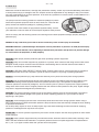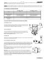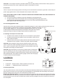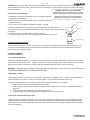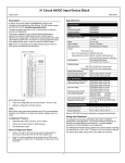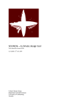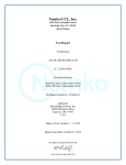
1
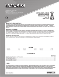
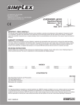
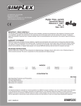
2525 GARDNER ROAD, BROADVIEW, IL 60155
1.800.323.9114 • Outside U.S. 1.708.865.1500
www.tksimplex.com
PET 2O SERIES
TORQUE WRENCH
PUMP
Reference # - 54393
Rev. - A
CONTENTS
Receiving Instructions and Warranty Statement .........................................................................................................1
Safe and Correct Use ............................................................................................................................................... 2-3
Technical Specifications ...............................................................................................................................................3
Working Pressure .........................................................................................................................................................3
Install Vent Plug ............................................................................................................................................................3
Adding Oil ..................................................................................................................................................................... 3
Install Hydraulic Connections .......................................................................................................................................3
Electrical ....................................................................................................................................................................... 4
Connecting Hydraulic Tools..........................................................................................................................................4
Starting the Pump for the First Time ............................................................................................................................4
Control Valves...............................................................................................................................................................4
Running the Pump........................................................................................................................................................4
Pressure Torque Setting ...............................................................................................................................................5
After Completing the Job .............................................................................................................................................5
Periodic Maintenance ...................................................................................................................................................5
Maintain Oil Level ......................................................................................................................................................... 5
Clean Oil Intake Screen ................................................................................................................................................5
Flushing the Pump .......................................................................................................................................................6
Problem / Cause - Solutions ........................................................................................................................................6
- Note SIMPLEX has taken every care in preparing this Operational Manual that is intended as a technical guideline only.
SIMPLEX accepts no liability in relation to any use or reliance made of any information in this Operational Manual.
All information, illustrations and specifications in this Operational Manual are based on the latest information
available at the time of publication. The right is reserved to make changes at any time without notice.
Equipment operators and installers shall be responsible for ensuring that a safe working environment and safe
systems of work are in place before operating the equipment.
* TO RETRIEVE TECHNICAL PART SHEET DOCUMENTATION, GO TO: www.tksimplex.com
©2008 SIMPLEX
••• 1 •••
PET 20 Series Torque Wrench Pumps
PET 2041 / 2041A
PET 2841 / 2841A
IMPORTANT - READ CAREFULLY
This manual contains important information for the correct installation, operation and maintenance of this
equipment. All persons involved in the installation, operation and maintenance of this equipment must be
thoroughly familiar with the contents of this manual. To safeguard against the possibility of personal injury or
property damage, follow the recommendations and instructions of this manual. Keep this manual for reference.
WARRANTY STATEMENT
SIMPLEX products are warranted to be free of defects in materials and workmanship under normal use for
as long as the original purchaser owns them, subject to the guidelines and limitations listed. This warranty does
not cover: normal wear & tear, cosmetic items, abuse, overloading, alterations, improper fluid, or use in a
manner for which they are not intended. If the customer believes a product is defective, the product must be
delivered, or shipped freight prepaid, to the nearest SIMPLEX Authorized Service Center for evaluation and
repair.
1.0 RECEIVING INSTRUCTIONS
Important! Make sure to inspect all of the components for shipping damage. If damage is found, notify carrier at
once. Shipping damage will not be covered by warranty. The carrier is responsible for all loss associated with
shipping damage.
www.tksimplex.com
2.0 SAFETY
••• 2 •••
Make sure to read the instructions, warnings and precautions carefully. Follow any recommended safety precautions
to avoid personal injury or damage to the unit. Simplex cannot be responsible for any damage or injury from unsafe
use, lack of maintenance or incorrect operation. In the event any questions or concerns arise, contact SIMPLEX or a
local Distributor for clarification.
The pump’s maximum working pressure is 10,000 PSI (700kg/cm2). Make
sure that all hydraulic equipment such as rams, hoses, etc. used with this
pump are rated at 10,000 PSI (700kg/cm2) operating pressure.
If you have never been trained on high-pressure hydraulic safety, consult
your distributor or service center for a free Simplex Hydraulic Safety Course.
Failure to comply with the following cautions and warnings could cause equipment damage, property damage or
personal injury.
DANGER is only used when your action or lack of action may cause serious injury or even death.
WARNING indicates a potential danger that requires correct procedures or practices to avoid personal injury.
CAUTION is used to indicate correct operating or maintenance procedures and practices to prevent damage
to, or destruction of equipment, or other property.
WARNING: Wear proper personal protective gear when operating hydraulic equipment.
WARNING: Stay clear of loads supported by hydraulics. A cylinder, when used as a load lifting device unless it was
designed for that purpose. It should never be used as a load holding device. After the load has been raised or
lowered, it must always be blocked mechanically.
WARNING: USE ONLY RIGID PIECES TO HOLD LOADS. Carefully select steel or wood blocks that are capable of
supporting the load. Never use a hydraulic cylinder as a shim or spacer in any lifting or pressing application.
DANGER: To avoid personal injury, keep hands and feet away from cylinder and work-piece during operation.
WARNING: Do not exceed equipment ratings. Never attempt to lift a load weighing more than the capacity of the
cylinder. Overloading causes equipment failure and possible personal injury. The cylinders are designed for a
maximum pressure of 10,000 PSI (700kg/cm2). Do not connect a jack or cylinder to a pump with a higher pressure
rating. Never set the relief valve to a higher pressure than the maximum rated pressure of the pump. Higher settings
may result in equipment damage and/or personal injury.
WARNING: The system operating pressure must not exceed the pressure rating of the lowest rated component in
the system. Install pressure gauges in the system to monitor operating pressure. It is your window to what is
happening in the system.
CAUTION: Avoid damaging hydraulic hose. Avoid sharp bends and kinks when routing hydraulic hoses. Using a
bent or kinked hose will cause severe back-pressure. Sharp bends and kinks will internally damage the hose, leading
to premature hose failure.
Do not drop heavy objects on hose. A sharp impact may cause internal damage to hose wire strands. Applying
pressure to a damaged hose may cause it to rupture.
IMPORTANT: Do not lift hydraulic equipment by the hose or swivel couplers. Use the carrying handle or other means
of safe transport.
CAUTION: Keep hydraulic equipment away from flames and heat. Excessive heat will soften seals, resulting in fluid
leaks. Heat also weakens hose materials. For optimum performance do not expose equipment to temperatures of
65° C (170° F) or higher. Protect hoses and cylinders from weld spatter.
••• 3 •••
DANGER: Do not handle pressurized hoses. Escaping oil under pressure can penetrate the skin, causing serious
injury. If oil is injected under the skin, see a doctor immediately.
DANGER: Only use hydraulic cylinders in a coupled system. Never use a cylinder with unconnected couplers. If the
cylinder becomes severely overloaded, components can fail catastrophically causing severe personal injury or death.
3.0 TECHNICAL SPECIFICATIONS
PET 2041 / 2841
Voltage
PET 2041A / 2841A
115V
Operating Pressure
220V
10,000 PSI (700kg/cm )
2
Electrical Power Source
15 Amps 115V Grounded 50/60 Hz
10 Amps 220V Grounded 50/60 Hz
Motor Rating
.5 Hp Permanent Magnet
10 Amps @ 10,000 psi (700kg/cm2)
.5 Hp Permanent Magnet
6 Amps @ 10,000 psi (700kg/cm2)
Flow Rate
400 cu. in./ min. @ 600 psi, 50 cu. in @ 10,000 psi (700kg/cm2)
Maximum Operating
Temperature
170�F - (65�C)
4.0 INITIAL INSTALLATION BEFORE OPERATING PUMP
4.1 Working Pressure
The pump’s maximum working pressure is 10,000 PSI (700kg/cm2). Make
sure that all hydraulic equipment such as rams, hoses, etc. used with this
pump are rated at 10,000 PSI (700kg/cm2) operating
pressure.
4.2 Install Vent Plug
Filler Plug
Location
Vent Plug
Location
Remove SHIPPING PLUG and install VENT PLUG into cover plate. Use
1.5 wraps of Teflon tape (or suitable thread sealant) on all threads, leaving
the first complete thread free of tape to ensure no foreign
matter enters the hydraulic circuit.
4.3 Adding Oil
Remove OIL FILLER CAP and add SIMPLEX Hydraulic Oil into reservoir. Oil level should
not exceed 1” from the reservoir cover.
"B"
4.4 Install Hydraulic Connections
Use only cylinders, tools, hoses and accessories rated at 10,000 PSI (700kg/cm2). Remove the shipping plugs from the ports to connect your coupling(s) or hose(s) to manifold. Use 1.5 wraps of Teflon tape (or suitable thread sealant) on all threads, leaving the
first complete thread free of tape to ensure no foreign matter enters the hydraulic
circuit.
When making connections with quick disconnect couplings, make sure the couplings
are fully engaged. Threaded connections such as fittings, gauges, etc. must be securely tightened and leak free.
WARNING: Loose or improperly threaded fittings can be potentially dangerous if
pressurized, however, severe over tightening can cause premature thread failure. Fittings need to be tightened secure & leak free. Never hold or stand directly in line with
any hydraulic connections while pressurizing. Never grab, touch or in any way come
in contact with a hydraulic pressure leak. Escaping oil can penetrate the skin and a
serious injury can result.
"A"
2 PORT FOR 1 TOOL USE
“B”
“A”
MULTI-PORT ADAPTER
8 PORTS FOR 4 TOOL USE
www.tksimplex.com
••• 4 •••
CAUTION: Do not subject the hose to potential hazards such as sharp surfaces, extreme heat or heavy impact. Do
not allow the hose to kink or twist. Inspect each hose for wear before it is used.
4.5 Electrical
Check for proper electrical supply before connecting. Be sure the electrical connection is grounded. Check that your
power supply agrees with the motor nameplate and/or Simplex model decal.
NOTE: MOTOR MAY SPARK. DO NOT OPERATE IN AN EXPLOSIVE ATMOSPHERE OR IN THE PRESENCE OF
CONDUCTIVE LIQUIDS.
a. Do not use a power or extension cord that is damaged or has exposed wires.
b. All single phase motors come equipped with a three prong grounding type plug to fit the
proper grounded type electrical outlet. Do not use a two prong ungrounded extension cord
as the pump’s motor must be grounded.
4.6 Connecting Hydraulic Tools
Use only tools, hoses and accessories rated at 10,000 PSI (700kg/cm2). When making connections with quick disconnect couplings, make sure the couplings are fully engaged. Threaded connections Black Button
such as fittings, gauges, etc. must be securely tightened and leak free. Use 1.5 wraps
of Teflon tape (or suitable thread sealant) on all threads, leaving the first complete
thread free of tape to ensure no foreign matter enters the hydraulic circuit.
Relief Assembly
4.7 Starting The Pump For The First Time
1.
2.
3.
Locate the valve control and make sure it’s in the neutral or open position.
Locate the power switch and select to the “ON” position. Check for any
leaks, repair as needed.
Shift the control valve to the closed, advance and retract position look for
movement in tool or cylinder. Check for any leaks, repair as needed.
CAUTION: Never operate the pump with the directional control valve in advance or retract at 10,000 PSI (700kg/cm2) without ram movement for more
than 1 minute. Leaving the valve in the advance or retract position without the
ram’s piston rod moving will overheat the oil.
CAUTION: Never disconnect or connect any hydraulic hoses or fittings without first unloading the ram, then unplug the electrical cord of the pump and
shift, or open all hydraulic controls several times to assure that the system has
been depressurized. If the system includes a gauge, double check the gauge
to assure pressure has been released.
"B"
ADV
ADV
Pendant Switch
"A"
2 PORT FOR 1 TOOL USE
5.0 OPERATION
“B”
5.1 Control Valves
2-Position 4 Way Solenoid Valve for Hydraulic Torque Wrenches
• To Advance......Depress switch in either position to advance tool.
• To Retract...........Release the switch to Retract tool.
5.2 Running the Pump
“A”
MULTI-PORT ADAPTER
8 PORTS FOR 4 TOOL USE
Turn main power switch on, which is located on the shroud and depress pendant switch to start the pump, let the
pump idle for one minute or until unit shuts off (only applicable for units equipped with time delay).This process is
done to carefully break in the pump, and make sure it’s primed with oil.
Bleeding the Hydraulic System - air can be removed from the system by fully advancing and retracting the hydraulic tool several times with the pump elevated so its reservoir is higher than the tool. When the trapped air is removed
from the hydraulic circuit, the tool will advance and retract smoothly. Sluggish tool action is usually the first sign of
air in the system.
••• 5 •••
CAUTION: Never operate the pump at 10,000 PSI (700kg/cm2) without tool movement for more than 1 minute
without shifting the control valve. Leaving the valve in the advance or retract position without the piston rod moving
will overheat the oil.
5.3 Pressure Torque Setting
WARNING: Make these adjustments BEFORE
putting torque wrench on nut or bolt head. The pump
pressure setting may be above the pressure needed
to provide the required torque for your application.
Exceeding required torque will cause equipment
damage and may lead to serious personal injury.
1. See torque wrench instructions for amount of pressure required
to produce desired torque.
2. Loosen lock nut and back out relief valve to prevent unintended
pressure build up.
3. Turn pump on. Press and the “ADVANCE” switch, and read
pressure gauge.
4. While holding the switch, turn relief valve in (clockwise) to increase pressure or
out (counter-clockwise) to decrease maximum pressure. Repeat until correct pressure
is obtained.
5. Tighten lock nut on the relief valve to maintain setting.
6. Run pump several times to test this setting before setting tool on the nut.
Adjusting Knob
Lock Nut
Valve Assembly
5.4 After Completing the Job
Before disconnecting hoses, fittings, etc., first, be sure the tool is unloaded and retracted, then unplug the power
cord and turn this adjusting knob counterclockwise or depress black release button to release system pressure.
Store the pump in a clean, dry area.
6.0 MAINTENANCE
6.1 Periodic Maintenance
Completely change the hydraulic oil and clean the oil filter screen and magnet (located in the reservoir) twice a year.
(Use Simplex oil only, Model # AO1, 1 gallon). Change the oil more frequently when used in extremely dusty areas or
when the oil has been overheated. Using oil other than Simplex Brand may void the pumps warranty.
WARNING: THE ELECTRICAL POWER CORD MUST BE DISCONNECTED FROM ELECTRICAL OUTLETS BEFORE
PERFORMING MAINTENANCE OR REPAIR PROCEDURES.
6.2 Maintain Oil Level
Check hydraulic oil level every 30 hours of operation. Add Simplex oil (Model # AO1 – 1 gallon) when necessary. Oil
level should be no more than 1” from top of reservoir plate – with cylinders retracted and motor off.
Change oil at least twice a year. The following conditions require more frequent oil changes.
• Rigorous duty, where oil temperature may reach 1500 F.
• High humidity environment and extreme changes in temperature that can result in condensation inside the
reservoir.
• Dirty or dusty environments that may contaminate the oil.
• Frequent connection and disconnection of hydraulic hoses and components.
6.2 Clean Oil Filter Screen Once A Year
Loosen and remove reservoir plate bolts. Lift pump unit off the reservoir, being careful not to damage the gasket.
Unscrew screen from bottom of pump unit and clean with nonflammable solvent. Blow dry and reassemble. Keep
areas around pump unobstructed to provide good air flow around the motor and pump. Keep the motor and pump
as clean as possible.
www.tksimplex.com
••• 6 •••
6.3 Flush The Pump
If you suspect your pump has been contaminated or discover sludge or other deposits on internal components, you
should thoroughly flush the pump. Remove the old oil from the reservoir, then thoroughly clean the reservoir and refill
with a clean, nonflammable flushing oil. Reassemble the pump and motor to the reservoir.
Now run the pump in no load condition for 1 or 2 minutes maximum. Unplug the pump and remove the motor and
pump assembly again. Now drain the flushing oil and re-clean the inside of the reservoir. (Make sure flushing fluid is
also drained from pump assembly). Refill the reservoir with Simplex hydraulic oil and reassemble the pump.
7.0 TROUBLESHOOTING
PROBLEM
Sporadic Tool Action:
Motor Will Not Start:
Noisy Operation:
Pump Oil is Over Heating:
CAUSE-SOLUTION
• Air in the hydraulic system. See Section 5.2 for correct bleeding procedure.
• Check reservoir oil level.
• Be sure power cord is not damaged.
• Check for tripped circuit breaker; be sure breaker is of adequate size.
• Have motor checked for proper operation.
• Have qualified electrician inspect for loose or faulty wiring or switch.
• Air in system.
• Be sure the oil reservoir is filled to normal level.
• Check all points where air might leak into system.
• Clogged or blocked intake screen.
• Back pressure problem, consult factory.
• Oil viscosity too high. Replace with Simplex Oil.
• Check for high pressure leakage at the pump (leaking at plug or relief valve).
• Oil level is low. Fill reservoir to normal level, or retrofit the pump with larger
reservoir or heat exchanger.
Pump Runs But Will Not Pump Oil:
• Pump is not primed. Run pump a few minutes tipping from side to side.
• Check to make sure that external adjustable relief valve set properly.
• Damaged O-Rings. Take to nearest Simplex authorized service center for repair.
• Defective control valve.
• Incorrect motor rotation, take to nearest Simplex Authorized Service Center.
2525 GARDNER ROAD, BROADVIEW, IL 60155
1.800.323.9114 • Outside U.S. 1.708.865.1500
www.tksimplex.com
UNITED STATES HOME OFFICE AND FACTORY
2525 Gardner Road, Broadview, IL 60155-3719
Phone: (708) 865-1500 • Fax: (708) 865-0894 • Toll Free: (800) 323-9114
Email: [email protected] • www.tksimplex.com
SIMPLEX PRODUCTS ARE WARRANTED TO BE FREE OF DEFECTS IN MATERIALS AND WORKMANSHIP UNDER NORMAL USE FOR AS LONG AS THE
ORIGINAL PURCHASER OWNS THEM, SUBJECT TO THE GUIDELINES AND LIMITATIONS LISTED. THIS WARRANTY DOES NOT COVER : NORMAL
WEAR AND TEAR, COSMETIC ITEMS, ABUSE, OVERLOADING, ALTERATIONS. IMPROPER FLUID, OR USE IN A MANNER FOR WHICH THEY ARE NOT
INTENDED. IF THE CUSTOMER BELIEVES A PRODUCT IS DEFECTIVE, THE PRODUCT MUST BE DELIVERED, OR SHIPPED FREIGHT PREPAID, TO THE
NEAREST SIMPLEX AUTHORIZED SERVICE CENTER FOR EVALUATION AND REPAIR.
Printed in the U.S.A.